Embed Size (px)
Citation preview

Engineering, 2011, 3, 755-762 doi:10.4236/eng.2011.37091 Published Online July 2011 (http://www.SciRP.org/journal/eng)
Copyright © 2011 SciRes. ENG
Design of Fuzzy PD-Controlled Overhead Crane System with Anti-Swing Compensation
Shebel Asad, Maazouz Salahat, Mohammed Abu Zalata, Mohammad Alia, Ayman Al Rawashdeh
Division of Mechatronics, Faculty of Engineering Technology, Al Balqa Applied University, Amman, Jordan
E-mail: [email protected], www.fet.edu.jo Received April 9, 2011; revised April 21, 2011; accepted May 5, 2011
Abstract This work aimed to find a proper control strategy to transfer loads using overhead cranes. The proposed con-trol strategy, which is Fuzzy PD-based, should take into account two main factors. First, the time needed to move the payload from the initial pick up point to the destination point that must be minimized. Second, the oscillation of the payload must be reduced to prevent hazards for people and equipment in the work place. The current work, presents a comparative analysis of fuzzy PD based control basing on classical PD ap-proach. A simplified model has been derived. The proposed control techniques have been designed and vali-dated with MatLab. Numerical comparative results have been obtained and discussed. Keywords: Induction Motor, Modeling, Stationary Reference Frame, Matlab/Simulink
1. Introduction One of the current trends in industry is that cranes be-came larger and higher. So they supposed to be faster in order to achieve acceptable transfer times. Unfortunately, cranes with large structures that are moving at high speeds are associated with undesirable payload oscilla-tions resulting from the system dynamics.
Cranes can be classified in terms of their mechanical structures and dynamics into three types: Overhead OHC e.g. (gantry), rotary, and boom cranes. Overhead crane (OHC) is a common type of cranes used to transfer the payload from one position to desired position. A gantry crane incorporates a trolley which moves along the track and translates in a horizontal plane [1].
In such cranes system, the load suspended from the trolley by cable is subject to swing caused by improper control input and disturbances. The failure of controlling crane may cause accident and may harm people and the surroundings. Therefore, such crane control must be able to move the trolley adequately fast and to suppress the payload swing at the final position. This is so-called anti-swing control [2].
In the present work, a Fuzzy PD (Proportional-Deriva- tive) has been designed basing on classical PD ap-proaches to ensure a robust and smooth position control
of the carte (trolley position) with the presence of an-other fuzzy-based anti-swing compensator. The proposed model has been validated with MatLab/Simulink, fuzzy logic and virtual reality toolboxes Numerical compara-tive results have been obtained to be found very ac-cepted.
To understand the overhead crane system, a simplified dynamic model has been derived that encounters the re-ality and complicities might be found with such type of cranes. The main feature of the derived model is its ca-pability to match real system’s nonlinearity (trolley posi-tion and swinging angle). 2. Derivation of a Simplified Dynamic Model
for OHC The first step in deriving the equations of motion using the Lagrangian approach is to find the positions of the load and position of the trolley with respect to the refer-ence point, then the kinetic and potential energies and dissipation function of the whole system would be found. Finally, the equations of motion are as given in 1 and 2 [3]:
From Figure 1, it could be mentioned that, actually, there are four main variables needed to control the over-head crane system: angular deviation (θ), angular velocity

S. ASAD ET AL.
Copyright © 2011 SciRes. ENG
756
Figure 1. A schematic of carte-pendulum system. ( ), trolley position (x) and trolley velocity ( x )
2
sin 2 cos
cos sin X
M m x ml ml
ml ml F
(1)
cos sin 2 0x l g l (2)
Equations (1) and (2) represent a nonlinear mathematical model of the overhead crane. Where LP is the position of the load with respect to the reference point O, TP is the position of the trolley with respect to the reference point O, Fx is the applied mechanical force in Newton, is the swinging angel of the payload in radians, m is the payload mass, M is the trolley mass, x is the trolley posi-tion and L is the robe length in meters. 2.1. Approximation of the Full Model The above derived model given in Equations (1) and (2) is an extremely nonlinear dynamic model. The nonlinear model could be approximated to simplify the progress of modeling in order to be used for numerical-control pur-poses.
Before the model linearization, a hypothesis for safe and smooth operation will be assumed; the swing angle and l would be kept small. As given in set of Equation (3).
2
sin
cos 1
0
M m
(3)
With this assumption, the simplified model of motion for the overhead crane system can be obtained as in Equation (4):
2
2 0
XM m x ml ml ml F
x l g l
(4)
By applying the above assumptions, a SS representa-tion could be achieved as shown below. 2.2. State Space Representation of the System After the simplification, Equation (4) can be re-written in state space representation as in Equation (5), and the equation of motion could be then obtained as shown in Equation (6):
1
2
3
4
Trolley position
Trolley velocity
Swing angle
Rate_Swing angle
xx
xxx
x
x
(5)
1 1
2 2
3 3
4 4
0 1 0 0 0
10 0 0
0 0 0 1 0
10 0 0
x
xx xmgxx xM Mx F
x x
M mx xg
ML ML
(6)
Output equation (y = Cx + Du) is as given in Equation (7),
1 0 0 0
0 0 1 0
x
xy
(7)
From the above described equations, it can be under-stood that the load (swing) angle (in other words, vibra-tion that could be occurred) depends on the applied force Fx, the trolley and load’s mass, the gravitational force and the length of the rope. The final simplified model can be built as shown in Figure 2.
With a model, shown in Figure 2, the trolley position would move to “infinity”, while the load swinging is within –0.07 to 0.07 radians. So, since the trolley is non-stop at any location, it seems to be necessary if the
Figure 2. Presents the configuration of the approximated model of overhead crane.

S. ASAD ET AL.
Copyright © 2011 SciRes. ENG
757
input to be modified in order to make the trolley stop, or in the worse condition, the trolley needs to be stopped at “somewhere” [4].
This will lead naturally to select a rectangular or “bang-bang” forcing function as an input vector. It seems that there is no mechanism or factor that makes the trol-ley stop (because the system model took an ideal situa-tion). Regarding on this, this input has been introduced in order to cope with this condition. In other point of view, this type of input is well known as a time-optimal solu-tion [5]. Regarding on this matter, modification of the selection of input shape has been done. This involves changing in system’s block diagram, as well as the input itself only. Figure 3 shows the new Simulink block dia-gram and the input force applied to the system. 2.3. Validation of the Simplified Model The effect in variation of input force, length of the hoist-ing rope, trolley mass and load mass on the dynamic be-havior of the overhead crane are investigated. The com-parative results are as shown below in Figure 4.
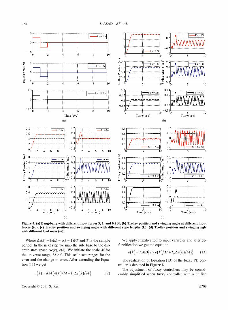
Figure 4 shows the response of the system in term of trolley position and swing angle when different input forces applied to the system (0.2, 1 and 5 N). We notice that when the input force is increase from 1 N to 5 N, the trolley is able to travel more distance where it can reaches around 2.8 m from its initial position. However the vibration of the trolley is greater. The magnitude of the load swing also increased to around 0.8 rad. But the frequency of the load remains the same. When input force decreased from 1 N to 0.2 N the trolley will only be able to reach around 0.12 m from its initial position. The magnitude of the load swing is decreased to approximate 0.033 rad. However the frequency of the load swing re-mained the same.
From Figure 4(c), we can see that the magnitude (0.2 rad) and frequency of the swing angle is greater. Trolley still can reach at 0.58 m at 2 s although the length of the hoisting rope decreased from 0.3 m to 0.2 m. However the fluctuation of the trolley increased with shorter rope. This is due to the load oscillation increased when the rope is shorter. As shown from Figure 4(d) when the load mass increased from 0.8 kg to 1.5 kg which means that the load mass is greater than the trolley mass the
Figure 3. New system configuration.
trolley (m < M) cannot reach more than 0.4 m and vibrate with obvious fluctuation, and the swing angle has high magnitude (0.09 rad) and frequency after the input force taken off. If the load mass decreased from 0.8 kg to 0.3 kg the trolley can reach about 0.78 m and almost stable, and the swing angle has low magnitude (5e–3) and fre-quency after the input force taken off at 2 s. 3. Control Design 3.1. Proposed Control Structure The structure of the proposed controller for the overhead crane system is shown in Figure 5. The proposed con-troller consists of fuzzy logic controllers for both posi-tion and anti-swing control respectively.
The objective of the proposed fuzzy logic controllers is to control the payload position X(s) so that it moves to the desired position Xref(s) as fast as possible without excessive swing angle of the payload (s). Here, the de-sign of fuzzy logic control is based on a classical control approach (proportional derivative control mode PD). It shows that fuzzy logic controller is a controller that may realize the skill of human operators and the design rules describe the subjective fuzziness of operators’ experi-ences instead of the use of mathematical model of the plant as modern control theory approaches. 3.2. Fuzzy PD Controllers Fuzzy PD controllers are physically related to classical PD controller. The parameters settings of classical and fuzzy controllers are based on deep common physical background. The introduced method considerably sim-plifies the setting and realization of fuzzy PD controllers [6-8]. A classical ideal PD controller is described as noted in Equation (8):
Du t K e t T e t (8)
We’d like to know when the action value is equal to zero, that is why we can write
0De t T e t (9)
The solution of Equation (9) is
De t e t T (10)
The Equation (10) depends only on the derivation time constant of the PD controller and its physical meaning is similar to Equation (4) for the PI controller. If we trans- fer the Equation (8) to the discrete form, we get an equa- tion of the discrete PD controller
Du k K e k T e k (11)
S. ASAD ET AL.
Copyright © 2011 SciRes. ENG
758
(a) (b)
(c) (d)
Figure 4. (a) Bang-bang with different input forces 5, 1, and 0.2 N; (b) Trolley position and swinging angle at different input forces (Fx); (c) Trolley position and swinging angle with different rope lengths (L); (d) Trolley position and swinging ngle with different load mass (m).
Where Δe(k) = (e(k) – e(k – 1))/T and T is the sample period. In the next step we map the rule base to the dis-crete state space Δe(k), e(k). We initiate the scale M for the universe range, M > 0. This scale sets ranges for the error and the change-in-error. After extending the Equa-tion (11) we get
Du k KM e k M T e k M (12)
We apply fuzzification to input variables and after de-fuzzification we get the equation
Du k KM e k M T e k M D F (13)
The realization of Equation (13) of the fuzzy PD con-troller is depicted in Figure 6.
The adjustment of fuzzy controllers may be consid-erably simplified when fuzzy controller with a unified

S. ASAD ET AL.
Copyright © 2011 SciRes. ENG
759
Figure 5. Proposed fuzzy PD-based overhead control system.
Figure 6. Fuzzy PD controller structure with the normalized universe range. universe is used. The parameters to be tune then have their physical meaning and fuzzy controller can be ap-proximately adjusted using known rules for classical PD controllers. Suitable choice of inference method can en-sure behavior, which is close to one of classical PD con-troller for both the tracking problem and the step distur-bance rejection [7].
The fuzzy sets are, as shown in Figure 7, assumed to have initially symmetrical layout and Ziegler-Nichols method, tunes the parameters of the proposed fuzzy PD-based position controller and either anti-swing com-pensator. 4. Simulation Results The above model concerning the fuzzy PD-based over-head crane system has been designed and validated with MATLAB/SIMULINK. The obtained comparative re-sults for both fuzzy PD and classical PD as positioning control and anti-swing compensation have been extracted with considering the setpoint tracking problems and the
step disturbance rejection, as shown in Figure 8. As concluded from Figure 8(a), it could be seen that
the performance of the closed loop control system using Fuzzy PD, when tracking the reference position Xref, is being enhanced with modification in dynamic state comparing with classical PD control structure.
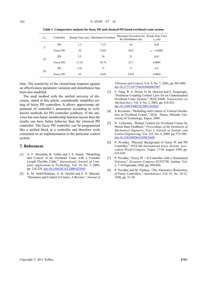
While the effect of the swing angle has been well elimi-nated using the proposed Fuzzy PD-controlled structure comparing with classical PD one (see Figure 8(b)). 5. Comparative Analysis The following table (Table 1) summarizes the net com-parative results shown above.
Where a comparative study for conventional PD con-troller with fuzzy PD one had been affected, then the comparative results are found at different set point values (Xref).
When considering of: rising time in seconds, maxi-mum overshoot, maximum overshooting in case of dis-turbance submission and steady-state error, it could be

S. ASAD ET AL.
Copyright © 2011 SciRes. ENG
760
(a)
(b)
Figure 7. Rule base and I/O fuzzy sets of proposed fuzzy PD controller (6-a) and anti-swing compensator (6-b)

S. ASAD ET AL.
Copyright © 2011 SciRes. ENG
761
(a)
(b)
Figure 8. Simulation comparative results of the proposed controllers (Fuzzy PD and classical PD) at set point tracking (Xref) and step disturbance effect (as shown inside the defined ellipse). (a) Controlled position; (b) Swinging angle. conclude that the overall steady state and dynamic per-formance of the proposed Fuzzy PD controlled plant seems to be better than that it was with classical ap-proach (PD).
These results that are being summarized in Table 1 have been validated at different carte positions (e.g. 5, 25
and 50). 6. General Conclusions It could be noticed the fuzzy PD-based control approach has enhanced the robustness and reduced the settling
S. ASAD ET AL.
Copyright © 2011 SciRes. ENG
762
Table 1. Comparative analysis for fuzzy PD and classical PD-based overhead crane system.
Xref Controller Rising Time (sec) Maximum OvershootMaximum Overshoot for
the Disturbance (m) Steady State Error
εss (m)
PD 3.5 7.15 56 0.05 5
Fuzzy PD 10 5.025 50.6 εss < 0.0001
PD 3.5 36 31 0.01 25
Fuzzy PD 11.32 29.75 25.7 0.0001
PD 3.42 71 11 0.5 50
Fuzzy PD 10 5.025 5.025 0.0002
time. The sensitivity of the closed-loop response against an effectiveness parameter variation and disturbances has been also modified.
The used method with the unified universe of dis-course, stated in this article, considerably simplifies set-ting of fuzzy PD controllers. It allows approximate ad-justment of controller’s parameters according to well- known methods for PD controller synthesis. If the uni-verse has non-linear membership function layout then the results can have better behavior than the classical PD controller. The fuzzy PD controller can be programmed like a unified block in a controller and therefore work consumed on an implementation to the particular control system. 7. References [1] A. F. Moustafa, B. Trabia and I. S. Ismail, “Modelling
and Control of an Overhead Crane with a Variable Length Flexible Cable,” International Journal of Com-puter Applications in Technology, Vol. 34, No. 3, 2009, pp. 216-228. doi:10.1504/IJCAT.2009.023945
[2] E. M. Abdel-Rahman, A. H. Nayfeh and Z. N. Masoud, “Dynamics and Control of Cranes: A Review,” Journal of
Vibration and Control, Vol. 9, No. 7, 2003, pp. 863-908. doi:10.1177/1077546303009007007
[3] Y. Fang, W. E. Dixon, D. M. Dawson and E. Zergeroglu, “Nonlinear Coupling Control Laws for an Underactuated Overhead Crane System,” IEEE/ASME Transactions on Mechatronics, Vol. 8, No. 3, 2003, pp. 418-423. doi:10.1109/TMECH.2003.816822
[4] S. Kiviluoto, “Modelling and Control of Vertical Oscilla-tion in Overhead Cranes,” M.Sc. Thesis, Helsinki Uni-versity of Technology, Espoo, 2009.
[5] N. Uchiyama, “Robust Control for Overhead Cranes by Partial State Feedback,” Proceedings of the Institution of Mechanical Engineers, Part I: Journal of Systems and Control Engineering, Vol. 223, No. 4, 2009, pp. 575-580. doi:10.1243/09596518JSCE698
[6] P. Pivoňka, “Physical Background of Fuzzy PI and PD Controller,” IFSA 8th International Fuzzy Systems Asso-ciation World Congress, Taipei, 17-20 August 1999, pp. 635-639.
[7] P. Pivoňka, “Fuzzy PI + D Controller with a Normalized Universe,” European Congress EUFIT’98, Aachen, Vol. 2, 7-10 Septembe 1998, pp. 890-894.
[8] P. Pivoňka and M. Findura, “The Alternative Realization of Fuzzy Controllers,” Automatizace, Vol. 41, No. 10-12, 1998, pp. 31-38.