Embed Size (px)
Citation preview
400 Commonwealth Drive, Warrendale, PA 15096-0001 U.S.A. Tel: (724) 776-4841 Fax: (724) 776-5760 Web: www.sae.org
SAE TECHNICALPAPER SERIES 2002-01-3308
Design of Formula SAESuspension Components
Badih A. Jawad and Brian D. PolegaLawrence Technological University
Reprinted From: Proceedings of the 2002 SAE MotorsportsEngineering Conference and Exhibition
(P-382)
Motorsports EngineeringConference & Exhibition
Indianapolis, IndianaDecember 2-5, 2002
All rights reserved. No part of this publication may be reproduced, stored in a retrieval system, ortransmitted, in any form or by any means, electronic, mechanical, photocopying, recording, or otherwise,without the prior written permission of SAE.
For permission and licensing requests contact:
SAE Permissions400 Commonwealth DriveWarrendale, PA 15096-0001-USAEmail: [email protected]: 724-772-4028Tel: 724-772-4891
For multiple print copies contact:
SAE Customer ServiceTel: 877-606-7323 (inside USA and Canada)Tel: 724-776-4970 (outside USA)Fax: 724-776-1615Email: [email protected]
ISSN 0148-7191Copyright © 2002 SAE International
Positions and opinions advanced in this paper are those of the author(s) and not necessarily those of SAE.The author is solely responsible for the content of the paper. A process is available by which discussionswill be printed with the paper if it is published in SAE Transactions.
Persons wishing to submit papers to be considered for presentation or publication by SAE should send themanuscript or a 300 word abstract of a proposed manuscript to: Secretary, Engineering Meetings Board, SAE.
Printed in USA
ABSTRACT
This paper is an introduction to the design of suspension components for a Formula SAE car. Formula SAE is a student competition where college students conceive, design, fabricate, and compete with a small formula-style open wheel racing car. The suspension components covered in this paper include control arms, uprights, spindles, hubs, pullrods, and rockers. Key parameters in the design of these suspension components are safety, durability and weight. The 2001 Lawrence Technological University Formula SAE car will be used as an example throughout this paper.
OVERVIEW
In designing suspension components for the 2001 Lawrence Technological University Formula SAE vehicle, safety and durability were the top priorities. In order to ensure the safety of the suspension system, the loads acting on every component were extensively studied by utilizing strength of material calculations and Finite Element Analysis. Another measure used to ensure the safety of the suspension system was that every suspension fastener was put into double shear and was either safety wired or secured with a locknut.
Weight was another important consideration while designing and manufacturing the suspension system on the 2001 Lawrence Technological University Formula SAE car. In order to achieve a weight reduction over previous Lawrence Technological University Formula SAE vehicles, Finite Element Analysis was utilized to remove the maximum amount of material from every suspension component while maintaining a critical safety factor of two. Also, chrome moly or 7075-T6 aluminum was used for every suspension component depending on which material was more practical considering any compatibility and dimensional restrictions. These materials were chosen due to their superior strength to weight ratios. The suspension load paths were also extensively studied to ensure that they were fed into the suspension system and frame in a robust manner.
SUSPENSION DESIGN
CONTROL ARMS
The purpose of the control arms is to secure the wheel assembly to the chassis. Coupled with the suspension geometry, the control arms play a key role in determining the kinematics of the car such as camber rejection and roll stability. [1] The control arms also provide a means for tuning the suspension for specific courses.
Figure 1: Assembled Rear Control Arms
In order to reduce weight, spherical bearings are staked into the pivot points and ball joints of the lower control arms, along with the rear upper control arm pivot points and front upper control arm ball joints instead of using traditional heavier rod ends at these locations. In order to stake the spherical bearings into the 4130 steel tubing, a hollow aluminum insert is pressed into the tubing. Non-tempered aluminum was used for the insert due to the fact that tempered aluminum is too hard to flatten, which causes the 4130 steel tubing to crack. Next, the end of the tube is crushed flat and a hole is milled through the flat end of the tubing. The bearing is then firmly staked into the control arm.
2002-01-3308
Design of Formula SAE Suspension Components
Badih A. Jawad and Brian D. Polega Lawrence Technological University
Copyright © 2002 SAE International
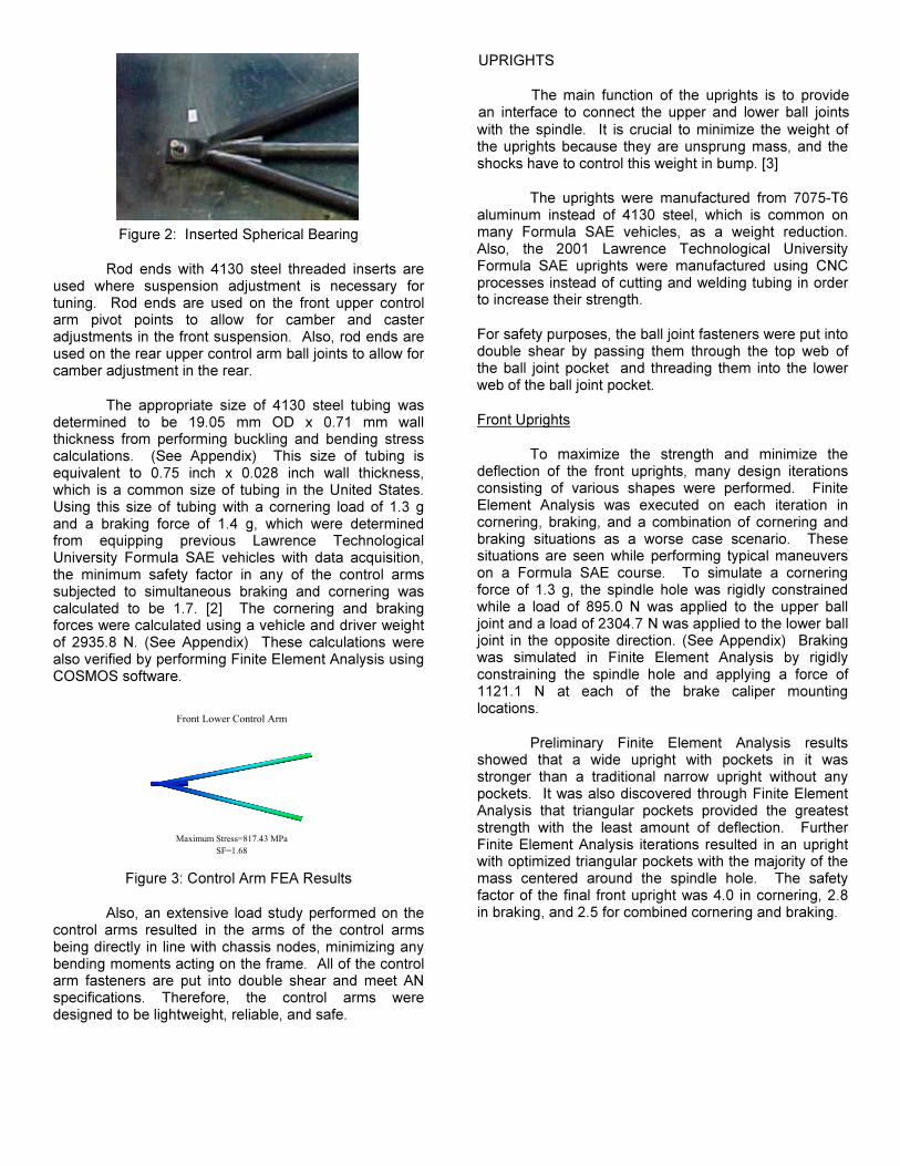
Figure 2: Inserted Spherical Bearing
Rod ends with 4130 steel threaded inserts are used where suspension adjustment is necessary for tuning. Rod ends are used on the front upper control arm pivot points to allow for camber and caster adjustments in the front suspension. Also, rod ends are used on the rear upper control arm ball joints to allow for camber adjustment in the rear.
The appropriate size of 4130 steel tubing was determined to be 19.05 mm OD x 0.71 mm wall thickness from performing buckling and bending stress calculations. (See Appendix) This size of tubing is equivalent to 0.75 inch x 0.028 inch wall thickness, which is a common size of tubing in the United States. Using this size of tubing with a cornering load of 1.3 g and a braking force of 1.4 g, which were determined from equipping previous Lawrence Technological University Formula SAE vehicles with data acquisition, the minimum safety factor in any of the control arms subjected to simultaneous braking and cornering was calculated to be 1.7. [2] The cornering and braking forces were calculated using a vehicle and driver weight of 2935.8 N. (See Appendix) These calculations were also verified by performing Finite Element Analysis using COSMOS software.
Figure 3: Control Arm FEA Results
Also, an extensive load study performed on the control arms resulted in the arms of the control arms being directly in line with chassis nodes, minimizing any bending moments acting on the frame. All of the control arm fasteners are put into double shear and meet AN specifications. Therefore, the control arms were designed to be lightweight, reliable, and safe.
UPRIGHTS
The main function of the uprights is to provide an interface to connect the upper and lower ball joints with the spindle. It is crucial to minimize the weight of the uprights because they are unsprung mass, and the shocks have to control this weight in bump. [3]
The uprights were manufactured from 7075-T6 aluminum instead of 4130 steel, which is common on many Formula SAE vehicles, as a weight reduction. Also, the 2001 Lawrence Technological University Formula SAE uprights were manufactured using CNC processes instead of cutting and welding tubing in order to increase their strength.
For safety purposes, the ball joint fasteners were put into double shear by passing them through the top web of the ball joint pocket and threading them into the lower web of the ball joint pocket.
Front Uprights
To maximize the strength and minimize the deflection of the front uprights, many design iterations consisting of various shapes were performed. Finite Element Analysis was executed on each iteration in cornering, braking, and a combination of cornering and braking situations as a worse case scenario. These situations are seen while performing typical maneuvers on a Formula SAE course. To simulate a cornering force of 1.3 g, the spindle hole was rigidly constrained while a load of 895.0 N was applied to the upper ball joint and a load of 2304.7 N was applied to the lower ball joint in the opposite direction. (See Appendix) Braking was simulated in Finite Element Analysis by rigidly constraining the spindle hole and applying a force of 1121.1 N at each of the brake caliper mounting locations.
Preliminary Finite Element Analysis results showed that a wide upright with pockets in it was stronger than a traditional narrow upright without any pockets. It was also discovered through Finite Element Analysis that triangular pockets provided the greatest strength with the least amount of deflection. Further Finite Element Analysis iterations resulted in an upright with optimized triangular pockets with the majority of the mass centered around the spindle hole. The safety factor of the final front upright was 4.0 in cornering, 2.8 in braking, and 2.5 for combined cornering and braking.
Front Lower Control Arm
Maximum Stress=817.43 MPaSF=1.68
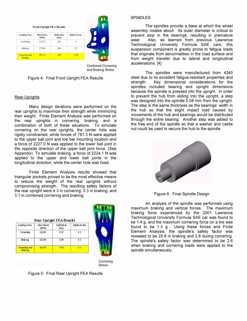
Figure 4: Final Front Upright FEA Results
Rear Uprights
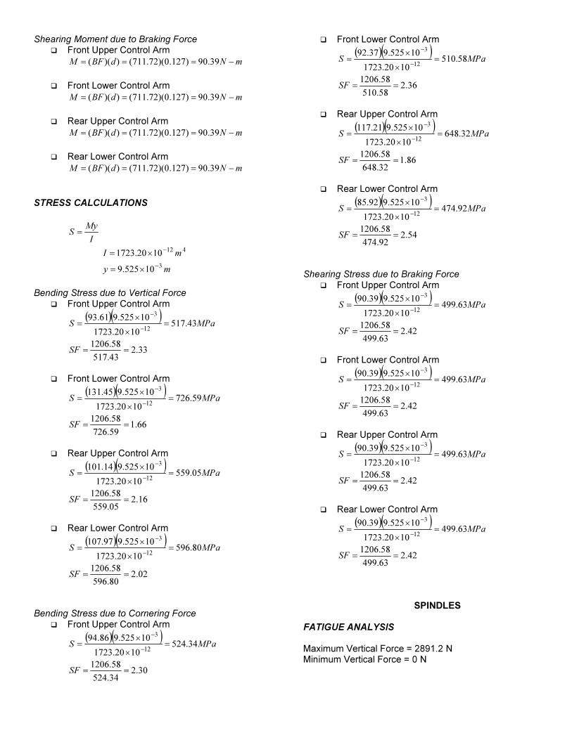
Many design iterations were performed on the rear uprights to maximize their strength while minimizing their weight. Finite Element Analysis was performed on the rear uprights in cornering, braking, and a combination of both of these situations. To simulate cornering on the rear uprights, the center hole was rigidly constrained, while forces of 781.3 N were applied to the upper ball joint and toe bar mounting location and a force of 2227.0 N was applied to the lower ball joint in the opposite direction of the upper ball joint force. (See Appendix) To simulate braking, a force of 2224.1 N was applied to the upper and lower ball joints in the longitudinal direction, while the center hole was fixed.
Finite Element Analysis results showed that triangular pockets proved to be the most effective means to reduce the weight of the rear uprights without compromising strength. The resulting safety factors of the rear upright were 4.3 in cornering, 3.3 in braking, and 3.1 in combined cornering and braking.
Figure 5: Final Rear Upright FEA Results
SPINDLES
The spindles provide a base at which the wheel assembly rotates about. Its outer diameter is critical to prevent slop in the bearings, resulting in premature wear. Also, as learned from previous Lawrence Technological University Formula SAE cars, this suspension component is greatly prone to fatigue loads that originate from abnormalities in the road surface and from weight transfer due to lateral and longitudinal accelerations. [4]
The spindles were manufactured from 4340 steel due to its excellent fatigue-resistant properties and strength. Key dimensional considerations for the spindles included bearing and upright dimensions because the spindle is pressed into the upright. In order to prevent the hub from sliding into the upright, a step was designed into the spindle 5.08 mm from the upright. The step is the same thickness as the bearings’ width in the hub so that the slight impact load caused by movements of the hub and bearings would be distributed through the entire bearing. Another step was added to the free end of the spindle so that a washer and castle nut could be used to secure the hub to the spindle.
Figure 6: Final Spindle Design
An analysis of the spindle was performed using maximum braking and vertical forces. The maximum braking force experienced by the 2001 Lawrence Technological University Formula SAE car was found to be 1.4 g, and the maximum cornering force on a tire was found to be 1.3 g. Using these forces and Finite Element Analysis, the spindle's safety factor was revealed to be 25.8 in braking and 2.8 during cornering. The spindle's safety factor was determined to be 2.6 when braking and cornering loads were applied to the spindle simultaneously.
Front Upright FEA Results
Loading Case Max Stress (MPa)
Deflection (mm)
Safety Factor
Cornering 123.35 .363 4
Braking 179.66 .044 2.8
Cornering and Braking
205.10 .409 2.45
Deflection
Combined Cornering and Braking Stress
Cornering Stress
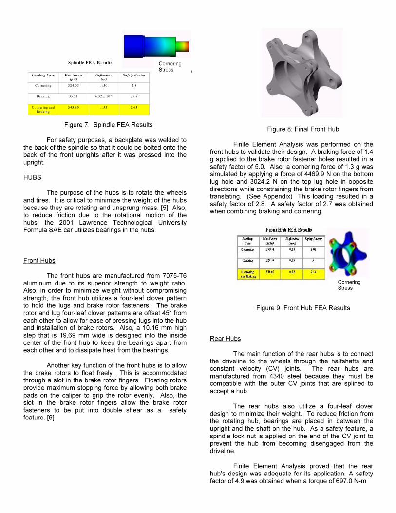
Figure 7: Spindle FEA Results
For safety purposes, a backplate was welded to the back of the spindle so that it could be bolted onto the back of the front uprights after it was pressed into the upright.
HUBS
The purpose of the hubs is to rotate the wheels and tires. It is critical to minimize the weight of the hubs because they are rotating and unsprung mass. [5] Also, to reduce friction due to the rotational motion of the hubs, the 2001 Lawrence Technological University Formula SAE car utilizes bearings in the hubs.
Front Hubs
The front hubs are manufactured from 7075-T6 aluminum due to its superior strength to weight ratio. Also, in order to minimize weight without compromising strength, the front hub utilizes a four-leaf clover pattern to hold the lugs and brake rotor fasteners. The brake rotor and lug four-leaf clover patterns are offset 45
0 from
each other to allow for ease of pressing lugs into the hub and installation of brake rotors. Also, a 10.16 mm high step that is 19.69 mm wide is designed into the inside center of the front hub to keep the bearings apart from each other and to dissipate heat from the bearings.
Another key function of the front hubs is to allow the brake rotors to float freely. This is accommodated through a slot in the brake rotor fingers. Floating rotors provide maximum stopping force by allowing both brake pads on the caliper to grip the rotor evenly. Also, the slot in the brake rotor fingers allow the brake rotor fasteners to be put into double shear as a safety feature. [6]
Figure 8: Final Front Hub
Finite Element Analysis was performed on the front hubs to validate their design. A braking force of 1.4 g applied to the brake rotor fastener holes resulted in a safety factor of 5.0. Also, a cornering force of 1.3 g was simulated by applying a force of 4469.9 N on the bottom lug hole and 3024.2 N on the top lug hole in opposite directions while constraining the brake rotor fingers from translating. (See Appendix) This loading resulted in a safety factor of 2.8. A safety factor of 2.7 was obtained when combining braking and cornering.
Figure 9: Front Hub FEA Results
Rear Hubs
The main function of the rear hubs is to connect the driveline to the wheels through the halfshafts and constant velocity (CV) joints. The rear hubs are manufactured from 4340 steel because they must be compatible with the outer CV joints that are splined to accept a hub.
The rear hubs also utilize a four-leaf clover design to minimize their weight. To reduce friction from the rotating hub, bearings are placed in between the upright and the shaft on the hub. As a safety feature, a spindle lock nut is applied on the end of the CV joint to prevent the hub from becoming disengaged from the driveline.
Finite Element Analysis proved that the rear hub’s design was adequate for its application. A safety factor of 4.9 was obtained when a torque of 697.0 N-m
Spindle FEA Results
Loading Case M ax Stress (psi)
Deflection (in)
Safety Factor
Cornering 324.05 .150 2.8
Braking 35.21 4.32 x 10⁻⁴ 25.8
Cornering and Braking
343.90 .155 2.63
CorneringDeflection
Cornering Stress
Cornering Stress

originating from the driveline was applied to the hub shaft while restraining the hub from rotating. When a cornering force of 1.3 g was simulated on the hub by placing a load of 3024.2 N on the top lug hole and 4469.9 N on the bottom lug hole in the opposite direction while preventing the shaft from rotating, the resultant safety factor was 4.2. (See Appendix) When combining a cornering situation with the torque acting on the hub, the resultant safety factor was 3.8.
Figure 10: Rear Hub FEA Results
ENERGY MANAGEMENT MECHANISMS
The energy management system consists of the pullrods, rockers, and shocks. The system’s purpose is to activate the inboard shocks, which greatly improves the handling qualities of the car. The geometry of the suspension mechanism is critical because it determines the motion ratio, which is the ratio of vertical wheel movement to shock displacement. This ratio is used to determine the car’s natural frequency, which significantly affects the car’s handling qualities. Friction is kept to an absolute minimum in the dampening system to allow for maximum efficiency of the shocks. [7] It is also critical that the pullrod, suspension mechanism, and shock are located in the same plane to eliminate bending moments on these suspension components.
Figure 11: Placement of Pullrod and Suspension Mechanism
Pullrods
Pullrods are utilized on the 2001 Lawrence Technological University Formula SAE car instead of pushrods, which are typically used on Formula SAE
vehicles, for a weight reduction. Smaller diameter tubing can be used for pullrods because when the car hits a bump, the pullrod pulls the suspension mechanism, which puts it in tension. During rebound the pullrods are subjected to an insignificant buckling load equivalent to the weight of the wheel assembly. Therefore, buckling does not have to be considered in the design of pullrods for a Formula SAE vehicle. However, a pushrod is subjected to a buckling load whenever the car goes into rebound, so buckling must be considered in the design of pushrods. Also, pullrods allow the rockers and shocks to be packaged towards the bottom of the car resulting in a lower center of gravity.
A stress analysis of the pullrods using a 1.4 g tensile force resulted in a maximum stress of 118.89 MPa. A safety factor of 2.6 is obtained from this stress. Finite Element Analysis was also performed on the pullrods to verify the stress calculations and resulted in a safety factor of 2.5.
Rockers
Rockers, commonly called bellcranks, were placed on the 2001 Lawrence Technological University Formula SAE car so that the shocks could be packaged inboard. This packaging scheme significantly reduces unsprung mass. Also, rockers allow the pullrod and shock displacements to be in different directions, which aids tremendously in the packaging of suspension components. The rockers were designed to have a one to one motion ratio, which means that the shocks travels the same amount that the wheel moves in the vertical direction. A one to one motion ratio was selected because it allows the total range of shock displacement to be used, which improves the sensitivity of the suspension system.
The rockers were manufactured from 7075-T6 aluminum due to its superior weight to strength ratio. To reduce friction in the energy management system, roller bearings were placed in between the two rocker plates and thrust bearings were incorporated into the bellcrank plates at the pivot points.
Extensive Finite Element Analysis was performed on the rockers to minimize their weight. A safety factor of 4.9 was obtained for the final design of the front rockers when a force of 1.3 g was applied to them at the pullrod attachment point while restraining it from translating. A safety factor of 4.5 was obtained for the rear rocker when it was loaded in a similar manner.
Cornering Stress

Figure 12: Rocker FEA Results
CONCLUSION
This paper addressed essential design considerations for a small formula-style open wheel racing car. These considerations were addressed properly because none of the suspension components on the 2001 Lawrence Technological University Formula SAE car failed during intensive driver’s training or at the 2001 Formula SAE competition.
ACKNOWLEDGMENTS
The authors would like to thank the 2001 Lawrence Technological University Formula SAE team for all of their hard work and effort put into the project.
REFERENCES
1. Smith, Carroll. Tune to Win. Fallbrock, CA: Aero Publishers, 1978.
2. Hibbeler, R.C. Mechanics of Materials. 3rd ed. Upper Saddle River, NJ: Prentice Hall, 1994.
3. David E. Woods and Badih A. Jawad. “Numerical Design of Racecar Suspension Parameters”, Wahington, D.C.: SAE International, 1999.
4. 2000 LTU FSAE Team, “2000 Formula SAE Final Report”, Southfield, Michigan: Lawrence Technological University, 2000.
5. Puhn, Fred. How to Make your Car Handle. Los Angeles, CA: HPBooks, 1981.
6. Smith, Carroll. Engineer to Win. Osceola, WI: Motorbooks International, 1984.
7. William F. Milliken and Douglas L. Miliken. Race Car Vehicle Dynamics. Warrendale, PA: SAE International.
Suspension Mechanism FEA Results
Stress Displacement
Rocker FEA Results

APPENDIX
SAMPLE CALCULATIONS
TOTAL WEIGHT
Target Vehicle Weight = 2224.11 N Average Driver Weight = 711.72 N Total Weight = 2224.11 + 711.72 = 2935.83 N
CONTROL ARMS
FRONT CONTROL ARM AXIAL FORCES
1445.7 N 4.40o 28.06
o
15.45o FUCA
FPR
FLCA
556.0 N
NF
NF
NF
F
FM
FF
FF
FF
FF
PR
UCA
LCA
oLCA
oLCA
oLCA
oPR
oUCAy
oLCA
oPR
oUCAz
0.233,2
6.208,1
7.259,2
)1.4)(40.4sin()8.21)(0.556(
)8.238)(40.4cos()381)(7.1445(0
40.4cos06.28cos
45.15cos7.14450
40.4sin06.28sin
45.15sin0.5560
−=
−=
−=
+−
+==+
+−
+==→+
−+
−==↑+
∑
∑
∑
)
REAR CONTROL ARM AXIAL FORCES
1445.7 N 4.13o 28.03
o
14.30o RUCA
RPR
RLCA
556.0 N
NR
NR
NR
R
RM
RR
RF
RR
RF
PR
UCA
LCA
oLCA
oLCA
oLCA
oPR
oUCAy
oLCA
oPR
oUCAz
0.088,2
5.060,1
3.267,2
)29.2)(13.4sin()64.8)(0.556(
)3.241)(13.4cos()381)(7.1445(0
13.4cos03.28cos
30.14cos7.14450
13.4sin03.28sin
30.14sin0.5560
−=
−=
−=
+−
+==+
+−
+==→+
−+
−==↑+
∑
∑
∑
)
BUCKLING CALCULATIONS
2
2
L
EIPcr
Π=
4121020.1723
84.206
mI
GPaE
−
×=
=
( ) ( )
NP
P
MAX
MAX
90.167,52
0176.00191.04
1058.1206226
=
−
Π×=
y
z
y
z

Front Upper Control Arm � Front Arm
( )( )( )
65.226.660,19
90.167,52
26.660,19
423.0
1020.17231084.206
2
1292
==
=
××Π=
−
SF
NP
P
cr
cr
� Rear Arm
( )( )( )
90.234.006,18
90.167,52
34.006,18
442.0
1020.17231084.206
2
1292
==
=
××Π=
−
SF
NP
P
cr
cr
Front Lower Control Arm � Front Arm
( )( )( )
01.458.009,13
90.167,52
58.009,13
520.0
1020.17231084.206
2
1292
==
=
××Π=
−
SF
NP
P
cr
cr
� Rear Arm
( )( )( )
49.406.629,11
90.167,52
06.629,11
550.0
1020.17231084.206
2
1292
==
=
××Π=
−
SF
NP
P
cr
cr
Rear Upper Control Arm � Front Arm
( )( )( )
15.367.552,16
90.167,52
67.552,16
461.0
1020.17231084.206
2
1292
==
=
××Π=
−
SF
NP
P
cr
cr
� Rear Arm
( )( )( )
66.355.241,14
90.167,52
55.241,14
497.0
1020.17231084.206
2
1292
==
=
××Π=
−
SF
NP
P
cr
cr
Rear Lower Control Arm
� Front Arm
( )( )( )
21.471.382,12
90.167,52
71.382,12
533.0
1020.17231084.206
2
1292
==
=
××Π=
−
SF
NP
P
cr
cr
� Rear Arm
( )( )( )
37.482.930,11
90.167,52
82.930,11
543.0
1020.17231084.206
2
1292
==
=
××Π=
−
SF
NP
P
cr
cr
MOMENT CALCULATIONS
M=Fd
Bending Moment due to Vertical Force
� Front Upper Control Arm
( )( )mNM
dVFM
−=
==
61.93
45.25cos413.045.25cos0.278))((00
� Front Lower Control Arm
( )( )mNM
dVFM
−=
==
45.131
40.14cos504.040.14cos0.278))((00
� Rear Upper Control Arm
( )( )mNM
dVFM
−=
==
14.101
30.24cos438.030.24cos0.278))((00
� Rear Lower Control Arm
( )( )mNM
dVFM
−=
==
97.107
13.14cos413.013.14cos0.278))((00
Bending Moment due to Cornering Force � Front Upper Control Arm
( ) mNdCFM −=== 86.94)117.0(45.15cos16.841))(( 0
� Front Lower Control Arm
( ) mNdCFM −=== 37.92)041.0(40.4cos70.2259))(( 0
� Rear Upper Control Arm
( ) mNdCFM −=== 29.117)114.0(30.14cos79.1061))(( 0
� Rear Lower Control Arm
( ) mNdCFM −=== 92.85)038.0(13.4cos81.2266))(( 0
Shearing Moment due to Braking Force � Front Upper Control Arm
mNdBFM −=== 39.90)127.0)(72.711())((
� Front Lower Control Arm
mNdBFM −=== 39.90)127.0)(72.711())((
� Rear Upper Control Arm
mNdBFM −=== 39.90)127.0)(72.711())((
� Rear Lower Control Arm
mNdBFM −=== 39.90)127.0)(72.711())((
STRESS CALCULATIONS
I
MyS =
my
mI
3
412
10525.9
1020.1723
−
−
×=
×=
Bending Stress due to Vertical Force � Front Upper Control Arm
( )( )
33.243.517
58.1206
43.517
1020.1723
10525.961.93
12
3
==
=
×
×
=−
−
SF
MPaS
� Front Lower Control Arm
( )( )
66.159.726
58.1206
59.726
1020.1723
10525.945.131
12
3
==
=
×
×
=−
−
SF
MPaS
� Rear Upper Control Arm
( )( )
16.205.559
58.1206
05.559
1020.1723
10525.914.101
12
3
==
=
×
×
=−
−
SF
MPaS
� Rear Lower Control Arm
( )( )
02.280.596
58.1206
80.596
1020.1723
10525.997.107
12
3
==
=
×
×
=−
−
SF
MPaS
Bending Stress due to Cornering Force
� Front Upper Control Arm
( )( )
30.234.524
58.1206
34.524
1020.1723
10525.986.94
12
3
==
=
×
×
=−
−
SF
MPaS
� Front Lower Control Arm
( )( )
36.258.510
58.1206
58.510
1020.1723
10525.937.92
12
3
==
=
×
×
=−
−
SF
MPaS
� Rear Upper Control Arm
( )( )
86.132.648
58.1206
32.648
1020.1723
10525.921.117
12
3
==
=
×
×
=−
−
SF
MPaS
� Rear Lower Control Arm
( )( )
54.292.474
58.1206
92.474
1020.1723
10525.992.85
12
3
==
=
×
×
=−
−
SF
MPaS
Shearing Stress due to Braking Force � Front Upper Control Arm
( )( )
42.263.499
58.1206
63.499
1020.1723
10525.939.90
12
3
==
=
×
×
=−
−
SF
MPaS
� Front Lower Control Arm
( )( )
42.263.499
58.1206
63.499
1020.1723
10525.939.90
12
3
==
=
×
×
=−
−
SF
MPaS
� Rear Upper Control Arm
( )( )
42.263.499
58.1206
63.499
1020.1723
10525.939.90
12
3
==
=
×
×
=−
−
SF
MPaS
� Rear Lower Control Arm
( )( )
42.263.499
58.1206
63.499
1020.1723
10525.939.90
12
3
==
=
×
×
=−
−
SF
MPaS
SPINDLES
FATIGUE ANALYSIS
Maximum Vertical Force = 2891.2 N Minimum Vertical Force = 0 N
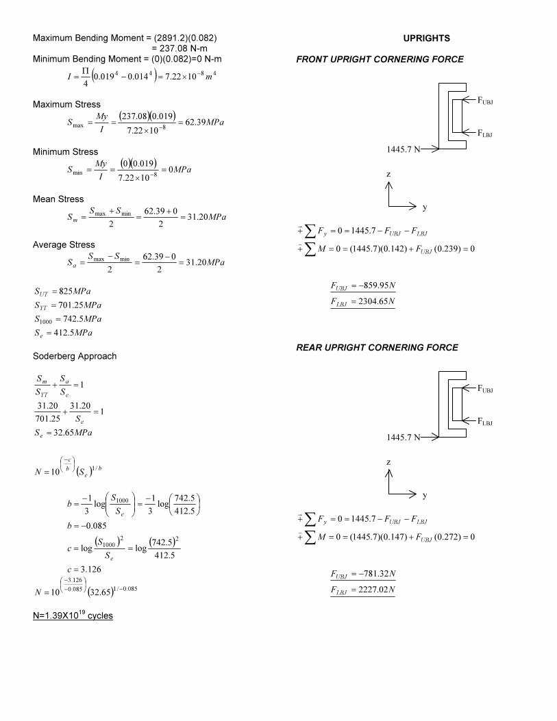
Maximum Bending Moment = (2891.2)(0.082) = 237.08 N-m Minimum Bending Moment = (0)(0.082)=0 N-m
( ) 48441022.7014.0019.0
4mI
−
×=−Π
=
Maximum Stress
( )( )MPa
I
MyS 39.62
1022.7
019.008.237
8max=
×
==−
Minimum Stress
( )( )
MPaI
MyS 0
1022.7
019.00
8min=
×
==−
Mean Stress
MPaSS
Sm
20.312
039.62
2
minmax=
+
=
+
=
Average Stress
MPaSS
Sa
20.312
039.62
2
minmax=
−
=
−
=
MPaS
MPaS
MPaS
MPaS
e
YT
UT
5.412
5.742
25.701
825
1000
=
=
=
=
Soderberg Approach
( ) b
e
b
c
e
e
e
a
YT
m
SN
MPaS
S
S
S
S
S
/110
65.32
120.31
25.701
20.31
1
−
=
=
=+
=+
( ) ( )
126.3
5.412
5.742loglog
085.0
5.412
5.742log
3
1log
3
1
22
1000
1000
=
==
−=
−=
−=
c
S
Sc
b
S
Sb
e
e
( ) 085.0/1085.0
126.3
65.3210−
−
−
=N
N=1.39X10
19 cycles
UPRIGHTS
FRONT UPRIGHT CORNERING FORCE
1445.7 N
FUBJ
FLBJ
y
z
∑
∑=+==+
−−==+
0)239.0()142.0)(7.1445(0
7.14450
UBJ
LBJUBJy
FM
FFF
)
r
NF
NF
LBJ
UBJ
65.2304
95.859
=
−=
REAR UPRIGHT CORNERING FORCE
1445.7 N
FUBJ
FLBJ
y
z
∑
∑=+==+
−−==+
0)272.0()147.0)(7.1445(0
7.14450
UBJ
LBJUBJy
FM
FFF
)
r
NF
NF
LBJ
UBJ
02.2227
32.781
=
−=

HUBS
FRONT HUB CORNERING FORCE
1445.7 N
FUL
FLL
y
z
∑
∑+==+
−−==+
)0.98()0.205)(7.1445(0
7.14450
UL
ULLLy
FM
FFF
)
r
NF
NF
LL
UL
87.4469
17.3024
=
−=
REAR HUB CORNERING FORCE
1445.7 N
RUL
RLL
y
z
∑
∑+==+
−−==+
)0.98()0.205)(7.1445(0
7.14450
UL
ULLLy
RM
RRF
)
r
NR
NR
LL
UL
87.4469
17.3024
=
−=
PULLRODS
TENSILE STRESS
A
P=σ
( ) 252210432.20077.00095.0
4mA
−
×=−Π
=
( )
61.289.118
26.310
89.118
10432.2
7.14452
5
==
=
×
=−
SF
MPaσ


![[PPT]2012 Formula SAE - Outboard Suspension - - pdx.eduweb.cecs.pdx.edu/~far/Past Capstone Projects/2012/FSAE... · Web view2012 Formula SAE Outboard Suspension Jose Colin EfeYildirim](https://img.pdfslide.us/doc/110x75/5ae0fda77f8b9a1c248dd435/ppt2012-formula-sae-outboard-suspension-pdx-farpast-capstone-projects2012fsaeweb.jpg)


![Formula SAE - Steering & Suspension Design - [ IntensePotential.com]](https://img.pdfslide.us/doc/110x75/55cf9284550346f57b970e81/formula-sae-steering-suspension-design-intensepotentialcom.jpg)