Embed Size (px)
Citation preview

International Journal of Latest Technology in Engineering, Management & Applied Science (IJLTEMAS)
Volume VII, Issue III, March 2018 | ISSN 2278-2540
www.ijltemas.in Page 211
Design of Floating Point Multiplier using Modified
Wallace & Dadda Algorithms Prof. Jyoti Goudar
1, Prof. A H Birasal
2
1, 2Assistant Professor, E & C Department, REC Hulkoti, Gadag, Karnataka, India
Abstract: - In computing, floating point describes a method of
representing an approximation of a real number in a way that
can support a wide range of values. Low power consumption and
smaller area are some of the most important criteria for the
fabrication of DSP systems and high performance systems.
Optimizing the speed and area of the multiplier is a major design
issue. This can be achieved using Wallace and Dadda algorithm
of an IEEE 754 single precision floating point multiplier.
Improvement in speed multiplication of Dadda and Wallace
multiplier is done using carry look ahead adder. Multiplier based
on Wallace and dada algorithms provides an area efficient and
high speed multiplication. The focus of this project is delay
comparison of floating point multiplier using Wallace tree and
Dadda tree algorithms. The Dadda tree multiplier is faster than
Wallace tree multiplier. Both uses XOR operation for sign bit
calculation and bias is used for exponent calculation. But
mantissa multiplication is calculating separately by using two
different techniques, those are Wallace and Dadda tree.
Wallace and Dadda tree involves three steps:[1]Generating
partial product using booth algorithm.[2]Partial products are
added using full adder and half adder until it is reduced to two
rows.[3] Final two rows are added using carry look ahead adder.
Now a day’s speech, video and other such real time
applications are required for mobile systems. For example cell
phone and laptop. Improving multipliers design directly benefits
the high performance embedded processors used in consumer
and industrial electronic products. The floating point multiplier
should be implemented to present both fast multiplication and
less hardware. Higher processor has been broadly used in
computer.
I. OBJECTIVE
he main objective of this study is to achieve high speed
single precision multiplication using booth algorithm in
Wallace and Dadda tree. This is achieved using verilog HDL
code. The generated partial products are added using full
adders and half adders. For final two rows addition carry look
ahead adder is used to calculate product of two floating point
numbers.
II. SCOPE OF THE PAPER
The aim here is to design and implement single precision
floating point multiplier using Wallace and Dadda tree
algorithm on Virtex 5.
Tools used for simulation
Xilinx ISE 14.2 design suite is used to implement floating
point multiplier using Wallace and Dadda algorithm in verilog
HDL.
III. FLOATING POINT MULTIPLICATION
. The IEEE 754 Standard is more used for floating point
multiplication and is adapted to many hardware and software
implementations.
The standard defines five basic formats depends on their base
and the number of bits used.
3.1 IEEE 754 Standards for Binary Floating Point
Multiplication:
There are three binary floating point formats, which can be
encoded using 32, 64 or 128 bits. The first two binary formats
are the „single precision‟ and „double precision‟ formats of
IEEE 754-1985 and third is called „quad‟.
SIGN EXPONENT MANTISSA
31 30 22 0
IEEE (Institute of Electrical & Electronics Engineering.)
numbers are stored using scientific notation.
± Mantissa*2exponent
We can represent single precision floating point numbers
with three binary terms:
1] Sign bit s: 1 bit.
2] Exponent field E‟: 8 bits.
3] Fraction field f: 23 bits.
E‟=E+127. 0 ≤ E‟ ≤ 255.
1) The actual exponent E IS IN THE RANGE OF -126
≤ E≤127
2) The basic aspects of working with floating point
numbers are two:
1. If number is not normalized, it can normalized by
shifting the fraction and adjusting the exponent.
(a) Un-normalized value:
0 10001000 00101100000000000000000
T

International Journal of Latest Technology in Engineering, Management & Applied Science (IJLTEMAS)
Volume VII, Issue III, March 2018 | ISSN 2278-2540
www.ijltemas.in Page 212
There is no implicit 1 to the left of the binary point.
Value represented=+0.0010110000….*29
(b) Normalized value:
0 10000101 01100000000000000000000
Value represented=+1.011000000….*26
The scale factor is in the form of 2i. Shifting the mantissa
right by one bit position is rewarded by an increase of 1 in
exponent. Shifting the mantissa left by one bit position is
rewarded by a decrease of 1 in exponent.
2. When computations precede, a number that does not fall in
the required range. In single precision floating point numbers
normalized representation requires an exponent less than -126
or greater than +127. In first case underflow has occurred. In
second case overflow has occurred. Both are arithmetic
exceptions.
3.1.1 Exceptions:
The IEEE standard defines 5 types of exceptions that occurred
when flag bit sets.
3.1.1.1 Invalid Operation
All exponent bits values are „1‟ and all the mantissa
bits are equal to „0‟, then it represents infinity. If all exponent
bits values are „1‟ and all the mantissa bits are not equal to
„0‟, and then it represents Not a Number (NaN). The result of
invalid operation is NaN (Not a number).
3.1.1.2 Division by zero
If divisor is zero in ordinary arithmetic there is no
meaning for this expression. In computer language integer
division by zero may cause a program to terminate and if
floating point numbers may cause NaN (Not a number) value.
Division by zero results infinity and the multiplication of two
numbers also results infinity. Therefore to differentiate
between the two cases, a divide by zero exception was
implemented.
3.1.1.3 Underflow and overflow
In two cases underflow exception occurs: tininess
and loss of accuracy. Tininess is detected after or before
rounding when a result lies between ±2Emin. Loss of
accuracy is detected when the result is when a
renormalizations loss occurs. The underflow exception occurs
whenever tininess is detected after rounding and at the same
time result is inexact. The overflow exception occurs
whenever the result exceeds the maximum value. It is not
occurred when one operand is infinity, because infinity is
always exact.
The sign bit is 0 for positive numbers and 1 for
negative numbers. The field f contains a binary fraction. The
actual mantissa of floating point value is (1+f). For example if
f is 01110111…, the mantissa become 1.01110111…There
are many ways to write a number in scientific notation, but
there is always a unique normalized representation, with
exactly one non-zero digit to the left of the point.
0.456*103=4.56*10
2=45.6*10
1
A side effect is that we get a little more precision for given
number. There are 24-bits in mantissa, but we need to store
only 23 of them. The exponent field represents the exponent
as a biased number. It consist actual component plus 127 for
single precision floating point numbers. This converts all
single precision exponents from -127 to 127 into unsigned
numbers from 0 to 254.
example shown below for single precision:
If exponent is 3, the e-field is 3+127=130=100000102
3.2 The binary representation of IEEE format for single
precision floating point number:
The decimal number is -12.375 that is first convert to binary
form. So the value is 1100.011(2). Normalize the number by
shifting the binary point until there is a single 1 to the left.
Shift binary point to left after 3-bits. i.e.
1100.011*20=1.100011*2
3
The exponent is 3. Therefore in biased form it is
130=10000010.
The fraction is 100011.
-12.375
1 10000010 10001100000000000000000
3.3 Floating point conversion to IEEE 754 format:
Ex1: The decimal number is 147.625
Step1: Convert decimal number to its equivalent binary
fractional form.
147.625=10010011.101
Step2: Normalize the binary fractional number.
10010011.101=1.0010011101*27
Step3: Convert the exponent to 8-bit excess-127 notation. Add
127 to exponent and convert it to 8-bit binary number.
7+127=134=10000110
Step4: Convert mantissa to buried bit format.
1.0010011101 0010011101
Step5: Write down 1+8+23=32 bit binary number.
147.625=0 10000110 00100111010000000000000

International Journal of Latest Technology in Engineering, Management & Applied Science (IJLTEMAS)
Volume VII, Issue III, March 2018 | ISSN 2278-2540
www.ijltemas.in Page 213
3.4 Floating point multiplier block diagram
Fig3.4: Block diagram of floating point multiplier
The above figure shows block diagram of floating point
multiplier. It consist mainly five steps:
Step1: The sign of floating point number n1 and n2 are
logically XOR together.
Sign=Sign1 XOR sign2. If both inputs are 0, then output is 0.
If sign1 is 0 and sign2 is 1, then output is 1. If sign1 is 1 and
sign2 is 0, then output is 1. If both inputs are 1, then sign
output is 0.
Step2: IEEE exponents are stored as 8-bit unsigned integers
with a bias of 127. Take example 1.10101*23 the exponent is
3 added to 127 and sum is 130 (100000102).If binary exponent
is unsigned; it cannot be negative. The largest possible
exponent is 128. It is added with 127 and sum is 255. This is
largest unsigned value represented by 8-bits.The range is from
1.0*2-127
to 1.0*2+128
The exponent is calculated by adding
both exponent of floating point numbers and the result is
subtracted from bias (127). E=E1+E2-127
Step3: The mantissa is calculated by multiplying both
mantissa of floating point numbers.
M=M1*M2. Multiplication is done using any algorithm.
Those are array multiplier, booth multiplier, parallel
multiplier, conventional Wallace multiplier, Wallace with
booth multiplier, dadda multiplier etc. Due to large delay of
multipliers, different methods have been designed to increase
speed. The partial products are generated using booth
algorithm. The partial product bits are added using half adders
and full adders until two rows get, at finally these rows are
added using fast carry look ahead adder. Dadda multiplier
algorithm is faster than remaining all types of multipliers. If
without booth algorithm multiplication is performed then it
generates more number of multiplications. It takes more delay
to execute. Multiplication is a basic and important building
block in all arithmetic logic units.
Step4: Normalize the result value if value is un-normalized, so
that there is a 1 just before the decimal point. Shifting decimal
point one place to the left increments the exponent by 1,
Moving one place to right decrement the exponent by 1. For
example, decimal number is 4566.23 is normalized as
4.56623*103. Same way the floating point binary value
1100.100 is normalized as 1.100100*23
by moving the
decimal point 3 positions to the left and multiplying by 23.In a
normalized mantissa, the digit 1 always appears to the left of
the decimal point. The leading 1 is lost from the mantissa in
the IEEE storage format because it is redundant. Sign,
exponent and normalized mantissa are grouped into the binary
IEEE representation.
Step5: If mantissa bits are more than 5-bits rounding is
required. If we applied the truncation rounding method then
the mantissa is 5-bits.At finally product of two floating point
numbers is getting using IEEE standard.
3.5 Floating point multiplication algorithm:
Fig3.5a: Flowchart of floating point multiplier
The following algorithm is used to multiply two floating point
numbers:
1).Multiplication (1.M1*1.M2): Its response is multiplying
the unsigned significant and putting the decimal point in the
multiplication product. Multiplication is performed on 23-bits.
Operands x and y are used for multiplication. The floating
point number x consist of sign bit s_ x, exponent bits e_ x and
mantissa bits m_ x. The floating point number y consists of
sign bit s_ y, e_ y and mantissa bits m_ y.
1. Putting the decimal point in the product.
2. Adding the exponents (e_ out=e_ x + e_ y –127): Its
response is to add two floating point number exponents and
sum is subtracted from bias 127. An 8-bit carry look ahead
adder is used to add two input exponents. This adder uses
generate and propagate functions. Gi is referred as the carry
generate signal. So carry C i+1 is generated whenever Gi =1. Pi
is referred as the carry propagate signal. When Pi =1, the
input carry is propagated to the output carry. C i+1=Ci.
Computing the values of P and G depends on input bits.

International Journal of Latest Technology in Engineering, Management & Applied Science (IJLTEMAS)
Volume VII, Issue III, March 2018 | ISSN 2278-2540
www.ijltemas.in Page 214
Fig3.5b: Block diagram of carry look ahead adder
Full adders are used to calculate sum, propagate and
generate bits. The ai, bi
and ci are input bits. Si and Ci+1 are output bits.
Pi= ai+ bi Gi= ai . bi
Si= ai xor bi xor ci
Ci+1=Gi + Pi.ci
Carry look ahead adder is faster because it generates carry
bits parallel by an additional logic circuit when inputs
change. It uses carry bypass logic ti speed up the carry
propagation.
4. Obtaining sign by performing the operation s1 XOR s2.
i.e. s_ out=s_ x XOR s_ y. Multiplying one negative number
and one positive number results negative number product.
If both numbers are positive or negative then product is
positive number. According to logical XOR truth table
multiplication is performed. When both inputs are 0 or 1, the
output is 0. When any one of the input is 0 or 1, the output is
1.
5. Normalizing the result: The result of the significant
multiplication is normalized to have a leading 1 to the left of
the decimal point. If product is 1010.0000100(2) then its
normalized value is 1.0100000100(2).
6. Rounding the result to fit in the 32-bits.
3.5.1 Floating point numbers multiplication examples:
Ex1: 12.52 * 15.25=190.93
12.52 1100.10000101
15.25 1111.01000000
Normalized value of first number is
1.10010000101*103
10010000101
Normalized value of second number is
1.11101000000*103
11101000000
Exp1=3+127=130=10000010
IEEE format of first number is:
0-10000010-10010000101000000000000
Exp2=3+127=130=10000010
IEEE format of second number is:
0-10000010-11101000000000000000000
Exp=Exp1+Exp2-127
=130+130-127
Exp=133
Mantissa multiplication:
1.10010000101
1.11101000000
--------------------------------------------------------------
000000000000
000000000000
000000000000
000000000000
000000000000
000000000000
110010000101
000000000000
110010000101
110010000101
110010000101
110010000101
-------------------------------------------------------------
10.1111101110110001000000
The normalized value of product is
1.01111101110110001000000 × 101
Total exp =product_ exp + exp -127
=1+133-127
Total exp =7
The product of mantissa of two numbers is
1.01111101110110001000000.
Shift decimal point to right after 7 bits. So the product is
10111110.1110110001000000(2) =190.93(10)
Normalized form of product is
1.01111101110110001000000*107
=
01111101110110001000000
Exp=7+127=134=10000110
Sign of product is 0.
IEEE form of product is:
0-10000110-01111101110110001000000
International Journal of Latest Technology in Engineering, Management & Applied Science (IJLTEMAS)
Volume VII, Issue III, March 2018 | ISSN 2278-2540
www.ijltemas.in Page 215
IV. BOOTH3 ALGORITHM
The 16-bit booth 3 multiplication concept is also used for 23-
bit booth 3 multiplication. Multiplier and multiplicand both
are 23-bits. The multiplier is divided into 8 groups. Each
group contains 4-bits binary value as shown in figure 4.1a.
4.1 Multiplication of two binary numbers using booth 3
algorithm
Fig4.1a: 16-bit booth 3 multiplication
In each group multiplier 4th
bit is checked and if it is 0 then
sign bit is S. If it is 1 then sign bit is ~S. The partial products
reduced from 23 to 9 by using boot 3 algorithms. The partial
product selection table is shown in figure. Each partial
product is chosen from the set 0, ±M, ±2M, ±3M, ±4M.
Except 3M all multiples are obtained from shifting and
complementing of the multiplicand.
The following steps are used to perform booth3 algorithm:
1) The multiplication of two 23-bits binary numbers using
Booth algorithm implies reduction in number of digits to 8 as
shown below figure 4.1b..
Fig4.1b: multiplier recoding
2) The partial products multiplexer selects one operation out
of nine possible operations depending on value of the
corresponding signed bit as shown in figure4.1c.\
M
~M
2M to Wallace or dadda
~2M tree To Wallace tree or
3M dadda tree
~3M
4M
~4M
Fig4.1c: Partial product multiplexer
3) The partial product multiplexer selects M if multiplier 4-
bits binary value is 0001 and ~M is selected when binary
value of multiplier is 1101. The multiplexer selects 2M when
binary value of multiplier is 0011. The multiplexer selects
~2M when binary value of multiplier is 1011. The partial
product multiplexer selects 3M when binary value of
multiplier is 0101.
For ex. The operation of 3M is:
y23 y22 y21 …. y3 y2 y1 y0 0 ( 2y )
y23 y23 y22 …. y4 y3 y2 y1 y0 ( y)
---------------------------------------------------------------z25 z24
z23 z22 …. z4 z3 z2 z1 z0 (3y)
4.2 Logic diagram of booth3 partial product generator
Fig4.2: 16-bit booth 3 partial product generator logic circuit
MUX

International Journal of Latest Technology in Engineering, Management & Applied Science (IJLTEMAS)
Volume VII, Issue III, March 2018 | ISSN 2278-2540
www.ijltemas.in Page 216
The above logic diagram shows booth 3 algorithm. This
modified booth algorithm is most used method to generate
partial product. This algorithm generates less partial products
compare to other techniques by using reduction method.
Therefore compression speed is enhanced. 2-bit, 3-bit, 4-bit
recoding is used for this algorithm. The 4-bit recoding means
that the multiplier B is divided into groups of four bits and the
algorithm is applied to this group. The booth algorithm is
implemented into two steps:
1) Booth decoding
2) Booth selecting
The booth encoding is used to produce one of the four
values in the multiplier group.
The booth selecting circuit is used to produce a partial product
bit k. This algorithm reduces partial products by a factor of 2,
without adding before to produce the partial products.fig
shows the dot diagram for a 23 *23 multiplication. The
multiplier is divided into overlapping groups of 4 bits and
each group is decoded to select a single partial product as per
the selection table. Each partial product is shifted 3 bit
positions with respect to its neighbors. The numbers of partial
products are reduced from 23 to 9. In general there is (n+2)/2
partial products, where n is the operand length. Many required
multiples are obtained by a simple shift of the multiplicand.
Negative multiples taken in two‟s complement form, which is
obtained using a bit by bit complement of the corresponding
positive multiples, with a 1 added at the least significant bit of
partial product. Booth algorithm also reduces dots in dot
diagram. In this partial product groups are assigned to a set
0,M,2M,3M,4M,-0,-M,-2M,-3M,-4M.
M is multiplicand value. –M is complement of
multiplicand value. 2M is circular left shift by 1-bit position. -
2M is circular left shift of complement of multiplicand 1-bit
position. 3M is (a+2a), that means „a „refers multiplicand and
2a is circular shift of a. -3M is complement of (a+2a) value.
4M is circular shift of multiplicand by 2-bit position. -4M is
complement of 4M value. The number of dots, constants and
sign are added is 126 for 23*23 multiplier and height of
partial product is now 9.
Generation of the multiple 3M requires adder circuit. It
cannot be obtained by simple shifting or complementing of
multiplicand. This increases the complexity of the partial
product generation. The amount of hardware and delay
depends upon number of partial products to be added. Booth
algorithm generates less partial products, so hardware cost is
less and it improves performance of multiplier. Booth is used
in multiplier with long operands i.e. greater than 16-bits.
Booth 2 is fastest algorithm, booth 3 is power efficient and
booth 4 requires less area. In booth 3 algorithm starting 27
bits are dots and 28th
, 29th
and 30th
bits are sign bits, which are
S. 31th bit is complement of sign bit, that is ~S. If MP [3] is 0,
then sign is 0. So it represents S. If MP [3] is 1, then sign is 1.
So it represents ~S.
V. PROPOSED ALGORITHMS
5.1 Floating point multiplication using Wallace algorithm
In 1964 C.S.Wallace introduced a Wallace tree
multiplication algorithm. It includes three steps to multiply
two numbers.
Step 1: The partial products are generated using booth 3
algorithm. Nine partial products are generated. Two 23-bit
numbers are used as inputs, those are multiplicand and
multiplier. The multiplier input is divided into 8 groups. Each
group consists of 4-bit binary value. If 0001 in the group then
multiplicand value should write as it is. If 0011 in the group
then 2* multiplicand value should write. Similarly
±3multiplicand and ±4multiplicand are represented for other
binary numbers shown in multiplication using booth3
algorithm table.
Step 2: In first stage the nine partial products are divided into
3 levels. In level-1 the full adder (3:2 counter) and half adders
(2:2 counter) are used for 3-bits and 2-bits respectively. The
full adder and half adder results sum and carry bits are stored
in 2nd
stage, level-1. In level-1 also same full adder and half
adders are used, these outputs sum and carry are stored in
further level. This continues in same way until two rows get.
Step3: These two rows are added using carry look ahead
adder. It is faster adder so the delay of multiplication is less.
Overall the multiplication consist 5 stages.Stage-1 consist of 3
levels. Stage-2 consists of 2 levels. Stage-3 consists of 1 level.
Stage-4 consist of 1 level and finally stage-5 also consist of 1
level i.e. using CLA the addition is performed. Two CLA‟s
are used to perform addition and to get product output. At
finally we get product of two numbers. Single precision 32-bit
floating point multiplication of two numbers consists of 1-bit
sign, 8-bits exponent and 23-bits mantissa. The 23-bit two
floating point numbers mantissa are multiplied using above
Wallace technique. The sign bit of first number and sign bit of
second numbers are XOR to get sign bit multiplication. When
both are 0 or 1, the output is 0. When any one output is 0 or 1,
the output is 1. Exponent is calculated using propagate and
generate function. Using carry look ahead adder the 8-bits of
exponent are added. The difference between Wallace tree
multiplier and column compression multiplier is that, in
Wallace tree each possible bit in each column is covered by
3:2 counter and 2:2 counter, until finally the partial product
has two rows. This algorithm consists of 5 stages.

International Journal of Latest Technology in Engineering, Management & Applied Science (IJLTEMAS)
Volume VII, Issue III, March 2018 | ISSN 2278-2540
www.ijltemas.in Page 217
Fig 5.1: Dot diagram of 23-bit Wallace multiplier.
Stage-1: It consists of 3 levels as shown in figure5.1. The
level-1 of stage-1 performs 36 full adders‟ functions. MP [0]
is 0th
bit of multiplier. It is always 0, because when grouping
the multiplier which contains 4 bits in each group we should
add 1 zero to multiplier. If MP [3] is 0, the sign
bit is 0 and it is represented as S. If MP [3] is 1, the sign bit is
1 and it is represented as ~S. Nine partial products are
produced using booth algorithm. These partial products are
divided in to 3 levels. The level-2 consists of 39 full adders
and level-3 consists of 35 full adders. The sum and carry
outputs of level-1 of stage-1 are stored in level-1 of stage-2.
Stage-2: Level-1 consists of 6 half adders and 30 full adders.
Level-2 of stage-1 sum and carry output bits are stored in this
stage-2.This continues until two rows get. The level-2 consists
of 5 half adders and 30 full adders.
Stage3: It consists of 12 half adders and 31 full adders. Two
dots are used for half adder operation and three dots are used
for full adder operation.
Stage4: It consists of 18 half adders and 30 full adders.
Stage5: Two CLA‟S are used to add last two rows of Wallace
algorithm.CLA1 add sum bits from S226 to S248 with carry
bits from C225 to C247. CLA2 add sum bits from S249 to
S271 with carry bits from C248 to C270. Two half adders are
used at beginning and end of stage-5. At finally we get
product of two binary numbers. Product is assigned from S0,
S110, S181, S224, and S272 to S321.
Totally Wallace multiplier uses:
1) Full adders=231.
2) Half adders=43.
3) CLA=2.
Wallace multiplier require more number of full adders, half
adders compare to Dadda multiplier. So Wallace is more
complex to design but Dadda multiplier is easy to design the
single precision floating point multiplier. Wallace multiplier
requires more wires compare to Dadda multiplier. Carry look
ahead adders are used to improve the speed of the design.
These are faster adders compare to all other adders because
they uses carry generate and propagate functions. The dot
diagram of Wallace multiplier is explained above clearly.
Stage levels are reduced as stage number increase. Final stage
is carry look ahead adder, from that result product of two
numbers will get.
5.2 Floating point multiplication using Dadda algorithm
Dadda multiplier developed Wallace‟s multiplier by defining
a few counters in partial product reduction stage using carry
look ahead adder. Dadda uses many ways to compress the
partial product bits using 3:2 and 2:2 counters. Fig shows the
process of 23*23 bits dot diagram for dadda multiplier. Each
dot represents a bit. In first step columns having more than six
dots are reduced to 6 dots, next reduced to 4 dots, next
reduced to 3 dots and at final dots are reduced to 2 dots in a
column. These two rows are added using carry look ahead
adder. Each half adder uses two dots, outputs one in the same
column and one in the next more significant column and each
full adder uses three dots, outputs one in same column and
one in the next more significant column so that no column in
step 1 will have more than 6 dots.
In each case the rightmost dot of the pair that is
connected by a line is in the column from which the inputs
were taken from the adder. In next step reduction is no more
than 4 dots per column, further no more than three dots per
column, at last no more than two dots per column is
performed. The height of the matrices is obtained by
functioning back from the final two row matrix and restricting
the height of the each matrix to the largest integer that is no
more than 1.5 times the height of its successor. Each matrix is
produced from its predecessor in one adder delay. Since the
number of bits in the words to be multiplied, the delay of the
matrix reduction process that reduces is proportional to log n,
where n is word size. Final two row matrix can be
implemented as a carry look ahead adder and total delay for
this multiplier is proportional to the logarithm of the word size
n.
5.2.1 Partitioning the partial products:
Partial products are divided into two parts: part-o and
part-1. In which part-0 and part-1 consists of n columns. The
two parts are separately performed and finally added both
result together. The partial products of each part are reduced
to two rows by the using 3:2 counter and 2:2 counters by
referring dadda algorithm. The grouping of 3 dots and 2 dots
in same column refers to 3:2 and 2:2 counters respectively. S
and C denote partial sum and partial carry bits.

International Journal of Latest Technology in Engineering, Management & Applied Science (IJLTEMAS)
Volume VII, Issue III, March 2018 | ISSN 2278-2540
www.ijltemas.in Page 218
Part-0: (Stage-1):In stage-1 nine partial products are divided
into 3 levels as shown in figure5.2.1a. The partial products are
generated using booth 3 algorithm. MP [0] is always 0
because when grouping the multiplier bit 0 is replaced with
zero. Ex: Multiplier is 10010110110100010
Fig5.2.1a: Dot diagram of 23-bit Dadda multiplier.
By using logic diagram the 9 partial product generation
equation is wrote:
0 1 0 0 1 0 1 1 0 1 1 0 1 0 0 0 1 0 0
Extra bit 0 {MP [0]}
Using FOR loop partial products are generated. In each
group if MP [3] is 0, then sign bit is 0 and it is noted to S. If
MP [3] is 1, then sign bit is 1 and it bits noted as ~S. That
means complement of S is calculated. In level-1 one half
adder functions is performed and 15 full adders are
performed. In level-2 one half adder and 12 full adders are
used. In level-3 one half adder and 10 full adders are used.
Stage-2: S0, S1……..S15 bits are stored in level-1 of stage-2.
The generated carry output bits are written in next column by
one bit shift. The c0 is carried to next column where it is to be
added up with sum s1 of a 3:2 counter. The carry c1 of 3:2
counter is added to next column. Stage-2 full adders and half
adders outputs sums and carries are stored in next column in
level-1 and level-2. The output sums S16 to S28 are added to
previous sums and carries in level-1. Totally 21 full adders
and 1 half adder used in this level. In level-2 of stage-2 18 full
adders and 1 half adder and another 1 half adder are used to
perform addition.
Stage-3: It consists 1 half adder and 25 full adders. The
addition is used same process.
Stage-4: It consists of 2 half adder and 28 full adders. The bits
C62 and C107 are added using half adders. The process is
continues until two rows to get.
Stage-5: The two CLA‟S CLA1 and CLA2 and 5 half adders
are used to add the input bits.CLA is faster than other adders.
It uses carry propagate and generate functions. The starting
bits addition is performed using half adder. Four half adders
are used at beginning. Next S109 to S137 and C108 to C136
bits are added using two CLA‟S. At last using one half adder
for C137 and C172 the last sum bit S173 is getting. Also it
generates carry bit C173.Finally S138 to S173 are result sum
bits of part-0 in dadda algorithm.
C139 to C174 are result carry bits of part-0 in dadda
algorithm.
Fig5.2.1b: Dot diagram of 23-bit Dadda multiplier.
Part-1: (Stage-1):
The partial products are shifted upward to make a not more
than 6 bits in first step as shown in figure5.2.1b. The satge-1

International Journal of Latest Technology in Engineering, Management & Applied Science (IJLTEMAS)
Volume VII, Issue III, March 2018 | ISSN 2278-2540
www.ijltemas.in Page 219
consists of two levels. In level-1 half adders are 2 and full
adders are 6. P4 [38] and P5 [38] bits are added using half
adder. The starting bit is 31st bit. The partial product 31
st to
50th
bits are considered for calculation. P2 [31], P3 [31] and
P4 [31] bits are added using full adders. In this full adder „a‟
is treated as P2 [31], „b‟ is treated as P3 [31] and „Cin‟ is
treated as P4 [31]. In level-2 4 half adders are used.
Stage-2: It consists of two levels.Level-1 consists of 2 half
adders and 12 full adders. The sums of level-1 of stage-1 are
stored in level-1 of stage-2. In that level next column consists
of carry bits of level-1 of stage-1. In level-2, 3 half adders and
7 full adders are used. The sum and carry output bits of
previous stage bits are added using half adders and full adders
in next stage.
Stage-3: It consists of 3 half adders and 14 full adders. The
partial products P [7] and P[8] bits are added together.
Stage-4: It consists of 2 half adders and 17 full adders. The
partial products P [8] and P[9] bits are added together in
stage-4.
Stage-5: One CLA is used to perform addition of sum bits
from S228 to S245 and carry bits from C227 to C244.
Another 2 half adders are used at beginning bits and end bits.
At finally we get part-1 output of dadda multiplier. The result
sum bits are from S246 to S266 and carry bits are from C247
to C267. At last the product of two binary numbers will get by
adding part-0 output and part-1 output. From S138 to S169
are directly assigned to output and next 1 half adder and 2 full
adders are used. At last 18 half adders are used to get final
product.
Totally dadda multiplier uses:
1) Full adders=187.
2) Half adders=55.
3) CLA=3.
VII. SIMULATIONS AND RESULTS
The single precision floating point multiplier using
Wallace algorithm and dadda algorithms are designed using
Xilinx ISE 14.2 design suit and have been synthesized with
XC5VLX110T of Virtex-5 as the target device. Proposed
algorithm achieves from writing Verilog code. The delay of
single precision floating point multiplier using Wallace
algorithm is compared with delay of single precision floating
point multiplier using dadda algorithm. This chapter mainly
discusses the simulation results of floating point multiplier
using Wallace and dadda algorithm and analysis of
performance goals.
7.1 Exponent multiplication of two floating point numbers:
The two numbers are: 16.25 × -23.75
1) 16.25 =10000.01 =1.000001 × 10⁴
exp1=4+127=131=10000011
2) 23.75 =10111.11 =1.011111 × 10⁴
exp2=4+127=131=10000011
Inputs:
16.15 0 10000011
00000100000000000000000
23.75 1 10000011
01111100000000000000000
Sign=sign1 XOR sign2
=0 XOR 1 =1
exp =exp1+exp2-127
=131+131-127
Mantissa M=11.00000011111 = 1.100000011111
expf =135+1=136
Final exp is 136-127 = 9
M = 1100000011.1112 = 385.937510
Fig7.1: Two floating point number exponent multiplication output
The product exponent is calculated by adding two floating
point number exponents and addition result is subtracted from
bias 127.
Sign=1
exp =135=10000111
Product = 1 10000111
10000001111100000000000
International Journal of Latest Technology in Engineering, Management & Applied Science (IJLTEMAS)
Volume VII, Issue III, March 2018 | ISSN 2278-2540
www.ijltemas.in Page 220
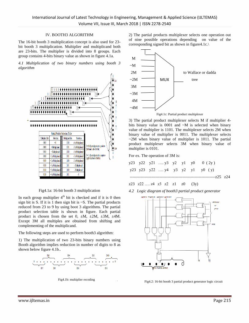
exp1=100000112=13110
exp2=100000112=13110
exp =exp1+exp2-127
=131+131-127=13510=100001112
The single precision floating point representation consist 8-bit
exponent. The exponent field represents the exponent as a
biased number. It contains the actual exponent plus 127 for
single precision. This converts all single precision exponents
from -127 to 127 into unsigned numbers from 0 to 254. The
resultant exponent is calculated using generate and propagate
functions in verilog code.
7.2 Generation of partial products using booth3 algorithm:
Fig7.2: Partial products output
The variables amp and amc are multiplier and
multiplicand binary values. Those are 23-bits wide. As
explained in chapter 4 each partial product is chosen from the
set 0, ±M, ±2M, ±3M, ±4M. Except 3M all multiples are
obtained from shifting and complementing of the
multiplicand. Using partial product generation table for 23-bit
mantissa nine partial products are generated.
The partial products are assigned as pp1, pp2, pp3,
pp4, pp5, pp6, pp7, pp8, pp9. Many intermediate wires and
registers are used to calculate partial products. FOR loop is
used to generate each partial product. To calculate 3M the 2M
is added with M. The partial product generation equation is
written using XOR, AND, OR and NOT basic logic gate
expressions. Without booth algorithm 23 partial products are
generating but using booth algorithm only 9 partial products
are generating.
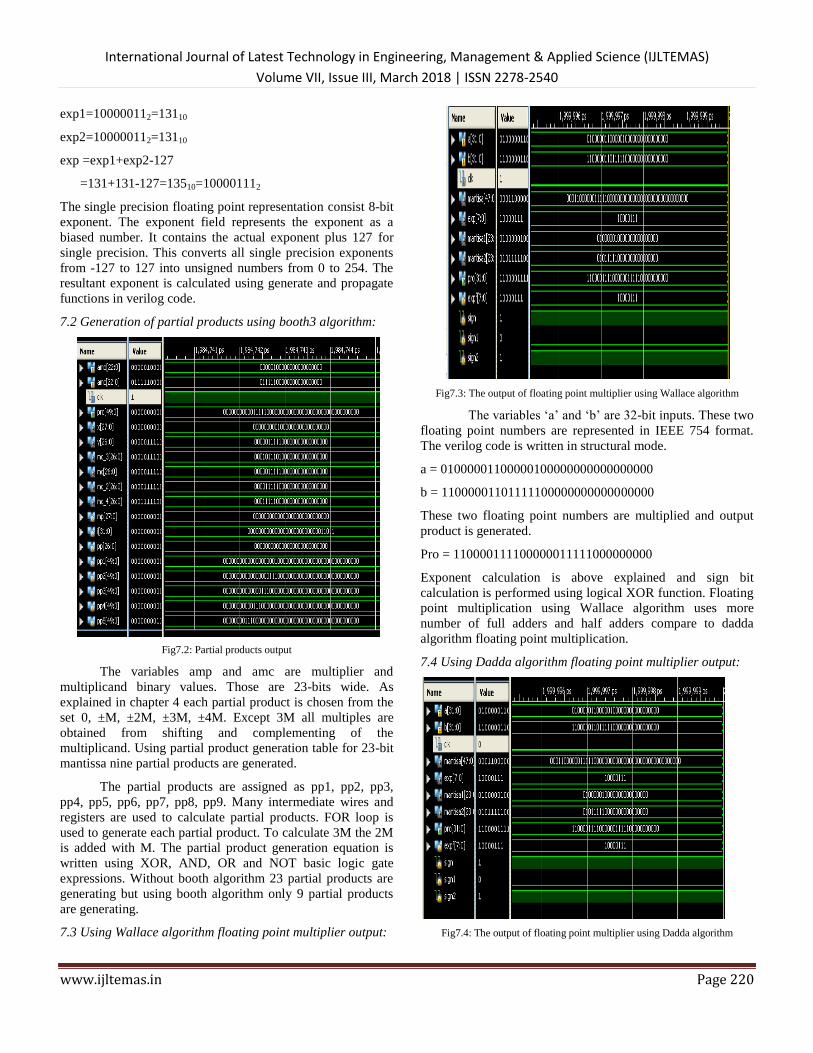
7.3 Using Wallace algorithm floating point multiplier output:
Fig7.3: The output of floating point multiplier using Wallace algorithm
The variables „a‟ and „b‟ are 32-bit inputs. These two
floating point numbers are represented in IEEE 754 format.
The verilog code is written in structural mode.
a = 01000001100000100000000000000000
b = 11000001101111100000000000000000
These two floating point numbers are multiplied and output
product is generated.
Pro = 110000111100000011111000000000
Exponent calculation is above explained and sign bit
calculation is performed using logical XOR function. Floating
point multiplication using Wallace algorithm uses more
number of full adders and half adders compare to dadda
algorithm floating point multiplication.
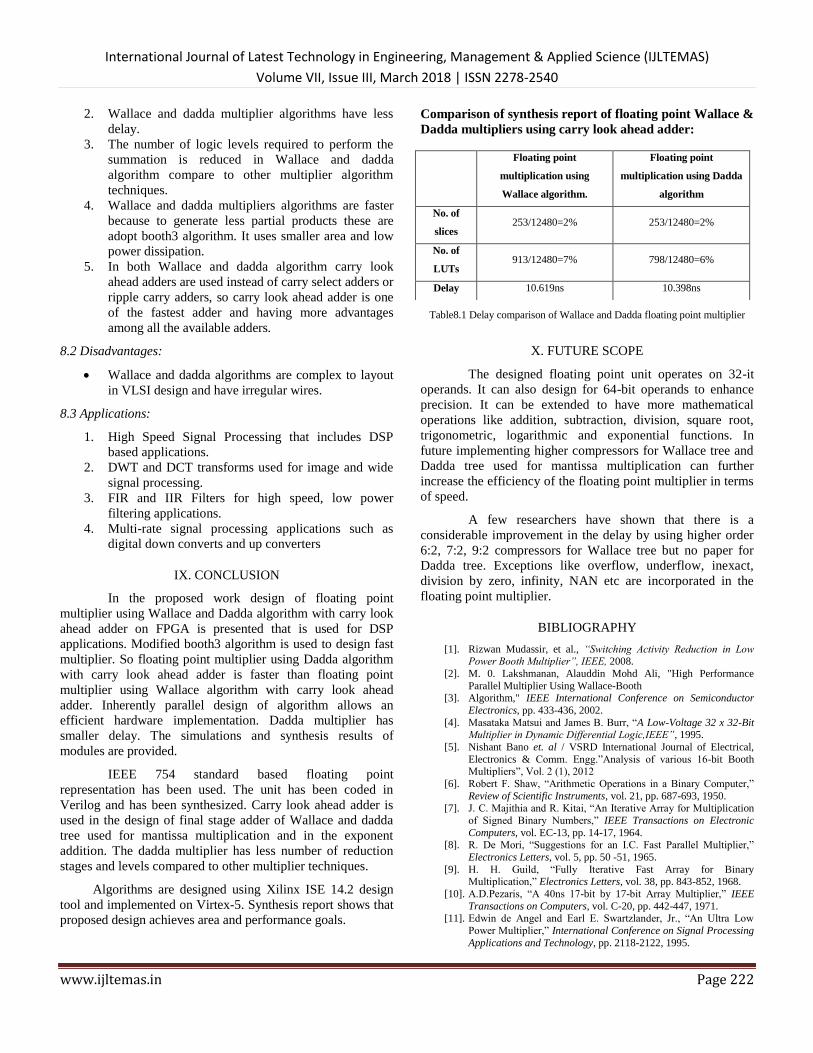
7.4 Using Dadda algorithm floating point multiplier output:
Fig7.4: The output of floating point multiplier using Dadda algorithm

International Journal of Latest Technology in Engineering, Management & Applied Science (IJLTEMAS)
Volume VII, Issue III, March 2018 | ISSN 2278-2540
www.ijltemas.in Page 221
Dadda algorithm floating point multiplication uses
same steps like Wallace algorithm but mantissa multiplication
is different.Booth3 algorithm generates 9 partial products. The
same partial product generation code is used for both Wallace
and dadda algorithms. In dadda algorithm the partial products
are divided in to 2 parts.
Part-0 and part-1 operations are separately performed
and finally these results are added together to get final product.
Dadda algorithm uses less full adders and half adders compare
to Wallace algorithm. Therefore it is faster than floating point
multiplier using Wallace algorithm. Mantissa1 and mantissa2
are 23-bit wide. The product is also IEEE754format. We can
convert that to decimal point number.
7.5 Device Utilization Summary
Common components such as flip-flops, LUTs,
block RAM and multiplexers make up the basic logic
structures on a Virtex-5. A collection of these basic structures
is called as slice or Configurable Logic Block (CLB). The
numbers of slice registers used are 253 and number of slice
LUTs are 958 in floating point multiplier using Wallace
algorithm. Information about map report and device
utilization will give whether design fits into the device or not.
Table7.5a: Design summary of floating point multiplier using Wallace algorithm.
Table7.5a and 7.5b shows the slice utilization for floating
point multiplication using Wallace and Dadda algorithm. As
shown in the table, both Wallace and Dadda algorithm
multiplication use 2% of the slice registers, LUTs, logics and
slices. Information about map report and device utilization
will give whether design fits into the device or not. As
proposed design uses 2% of the available resources, one can
tell that design fits into the Virtex-5.
Table7.5b: Design summary of floating point multiplier using dadda algorithm.
7.4.2 Timing Summary
The proposed solution processes data at a rate of 8 bytes
per cycle at 47.083MHz. Clock frequency is used to calculate
throughput. Timing summary provides statistics on average
routing delays and performance versus constraints.
Timing summary for floating point multiplier using
Wallace algorithm:
Speed grade:-2
Minimum period: 21.239ns
Minimum input arrival time before clock: 4.20ns
Maximum output required time after clock: 2.826ns
Maximum combinational path delay: No path found
Timing summary for floating point multiplier using Dadda
algorithm:
Speed grade:-2
Minimum period: 20.797ns
Minimum input arrival time before cloc4.200ns
Maximum output required time after clock: 2.826ns
Maximum combinational path delay: No path found
VIII. ADVANTAGES DISADVANTAGES AND
APPLICATIONS:
8.1 Advantages:
1. Floating point multiplier using Wallace and dadda
algorithm designs presented here are very lean and
require less resource when implemented on Virtex-5.
International Journal of Latest Technology in Engineering, Management & Applied Science (IJLTEMAS)
Volume VII, Issue III, March 2018 | ISSN 2278-2540
www.ijltemas.in Page 222
2. Wallace and dadda multiplier algorithms have less
delay.
3. The number of logic levels required to perform the
summation is reduced in Wallace and dadda
algorithm compare to other multiplier algorithm
techniques.
4. Wallace and dadda multipliers algorithms are faster
because to generate less partial products these are
adopt booth3 algorithm. It uses smaller area and low
power dissipation.
5. In both Wallace and dadda algorithm carry look
ahead adders are used instead of carry select adders or
ripple carry adders, so carry look ahead adder is one
of the fastest adder and having more advantages
among all the available adders.
8.2 Disadvantages:
Wallace and dadda algorithms are complex to layout
in VLSI design and have irregular wires.
8.3 Applications:
1. High Speed Signal Processing that includes DSP
based applications.
2. DWT and DCT transforms used for image and wide
signal processing.
3. FIR and IIR Filters for high speed, low power
filtering applications.
4. Multi-rate signal processing applications such as
digital down converts and up converters
IX. CONCLUSION
In the proposed work design of floating point
multiplier using Wallace and Dadda algorithm with carry look
ahead adder on FPGA is presented that is used for DSP
applications. Modified booth3 algorithm is used to design fast
multiplier. So floating point multiplier using Dadda algorithm
with carry look ahead adder is faster than floating point
multiplier using Wallace algorithm with carry look ahead
adder. Inherently parallel design of algorithm allows an
efficient hardware implementation. Dadda multiplier has
smaller delay. The simulations and synthesis results of
modules are provided.
IEEE 754 standard based floating point
representation has been used. The unit has been coded in
Verilog and has been synthesized. Carry look ahead adder is
used in the design of final stage adder of Wallace and dadda
tree used for mantissa multiplication and in the exponent
addition. The dadda multiplier has less number of reduction
stages and levels compared to other multiplier techniques.
Algorithms are designed using Xilinx ISE 14.2 design
tool and implemented on Virtex-5. Synthesis report shows that
proposed design achieves area and performance goals.
Comparison of synthesis report of floating point Wallace &
Dadda multipliers using carry look ahead adder:
Table8.1 Delay comparison of Wallace and Dadda floating point multiplier
X. FUTURE SCOPE
The designed floating point unit operates on 32-it
operands. It can also design for 64-bit operands to enhance
precision. It can be extended to have more mathematical
operations like addition, subtraction, division, square root,
trigonometric, logarithmic and exponential functions. In
future implementing higher compressors for Wallace tree and
Dadda tree used for mantissa multiplication can further
increase the efficiency of the floating point multiplier in terms
of speed.
A few researchers have shown that there is a
considerable improvement in the delay by using higher order
6:2, 7:2, 9:2 compressors for Wallace tree but no paper for
Dadda tree. Exceptions like overflow, underflow, inexact,
division by zero, infinity, NAN etc are incorporated in the
floating point multiplier.
BIBLIOGRAPHY
[1]. Rizwan Mudassir, et al., “Switching Activity Reduction in Low Power Booth Multiplier”, IEEE, 2008.
[2]. M. 0. Lakshmanan, Alauddin Mohd Ali, "High Performance
Parallel Multiplier Using Wallace-Booth [3]. Algorithm," IEEE International Conference on Semiconductor
Electronics, pp. 433-436, 2002.
[4]. Masataka Matsui and James B. Burr, “A Low-Voltage 32 x 32-Bit Multiplier in Dynamic Differential Logic,IEEE”, 1995.
[5]. Nishant Bano et. al / VSRD International Journal of Electrical,
Electronics & Comm. Engg.”Analysis of various 16-bit Booth Multipliers”, Vol. 2 (1), 2012
[6]. Robert F. Shaw, “Arithmetic Operations in a Binary Computer,”
Review of Scientific Instruments, vol. 21, pp. 687-693, 1950.
[7]. J. C. Majithia and R. Kitai, “An Iterative Array for Multiplication
of Signed Binary Numbers,” IEEE Transactions on Electronic
Computers, vol. EC-13, pp. 14-17, 1964. [8]. R. De Mori, “Suggestions for an I.C. Fast Parallel Multiplier,”
Electronics Letters, vol. 5, pp. 50 -51, 1965.
[9]. H. H. Guild, “Fully Iterative Fast Array for Binary Multiplication,” Electronics Letters, vol. 38, pp. 843-852, 1968.
[10]. A.D.Pezaris, “A 40ns 17-bit by 17-bit Array Multiplier,” IEEE
Transactions on Computers, vol. C-20, pp. 442-447, 1971. [11]. Edwin de Angel and Earl E. Swartzlander, Jr., “An Ultra Low
Power Multiplier,” International Conference on Signal Processing
Applications and Technology, pp. 2118-2122, 1995.
Floating point
multiplication using
Wallace algorithm.
Floating point
multiplication using Dadda
algorithm
No. of
slices 253/12480=2% 253/12480=2%
No. of
LUTs 913/12480=7% 798/12480=6%
Delay 10.619ns 10.398ns

International Journal of Latest Technology in Engineering, Management & Applied Science (IJLTEMAS)
Volume VII, Issue III, March 2018 | ISSN 2278-2540
www.ijltemas.in Page 223
[12]. S. Shafiulla Basha1, Syed. Jahangir Badashah, “Design and
Implementation of radix-4 based high speed multiplier for alu‟s using minimal partial products” July 2012.314 Vol. 4, Issue 1, pp.
314-325
[13]. P. R. Cappello and K Steiglitz, “A VLSI layout for a pipe-lined Dadda multiplier,” ACM Transactions on Computer Systems
1,2(May 1983) ,pp. 157-17
[14]. Baugh, Charles R.; Wooley, B.A., "A Two's Complement Parallel Array Multiplication Algorithm," Computers, IEEE Transactions
on , vol.C-22, no.12, pp.1045,1047, Dec. 1973
[15]. Wallace, C. S., "A Suggestion for a Fast Multiplier," Electronic Computers, IEEE Transactions on , vol.EC-13, no.1, pp.14,17,
Feb. 1964
[16]. L. Dadda, “Some schemes for parallel multipliers,” Alta Frequenza, vol. 34, pp. 349–356, 1965
[17]. Townsend, W. Swartzlander, E. Abraham, J., "A Comparison of
Dadda and Wallace Multiplier Delays". SPIE Advanced Signal Processing Algorithms, Architectures, and Implementations XIII.
[18]. Kogge, Peter M.; Stone, Harold S., "A Parallel Algorithm for the
Efficient Solution of a General Class of Recurrence Equations," Computers, IEEE Transactions on , vol.C-22, no.8, pp.786,793,
Aug. 1973
[19]. Brent, Richard P.; Kung, H. T., "A Regular Layout for Parallel Adders," Computers, IEEE Transactions on , vol.C-31, no.3,
pp.260,264, March 1982
[20]. Han Tackdon, Carlson, D.A., "Fast area-efficient VLSI adders," Computer Arithmetic (ARITH), 1987 IEEE 8th Symposium on,
vol., no.,pp.49,56, 18-21 May 1987


![SPIM: A Pipelined 64 X 64 bit Iterative Multiplier · It has a core size of 3.8 X 6.5mm and contains 41 ... A Pipelined 64 X 64 bit Iterative Multiplier ... Dadda [4], and most other](https://img.pdfslide.us/doc/110x75/5afdb58a7f8b9a864d8deb59/spim-a-pipelined-64-x-64-bit-iterative-has-a-core-size-of-38-x-65mm-and-contains.jpg)