Embed Size (px)
Citation preview
24 NSCJune 16
Technical
IntroductionA simple rule of thumb approach to sizing partial penetration butt welds carrying longitudinal shear has sometimes been used where the resistance is based on the average shear stress used for checking the shear resistance of beam webs: 0.6py in BS 5950 or fy/√3 in EN 1993-1-1. This confusingly led to a lower shear resistance than that found when sizing the weld using the specified design strength. In what follows, the directional method in EN 1993-1-8 is discussed and examples of weld design are presented, showing the rule of thumb approach to be conservative and inappropriate.
Directional methodThe directional method for design of fillet welds and partial penetration butt welds in EN 1993-1-8 clause 4.5.3.2 involves checks of 1) combined stress and 2) direct stress on the weld throat and compares each with a different limiting stress denoted here by the general term σL. The limiting stresses are based on the ultimate strengths of the material (which are constant for most thicknesses up to 100 mm) and the values for different steel grades are given in the table below. The stresses are in MPa. A material factor of 1.25 (for bridges) has been used.
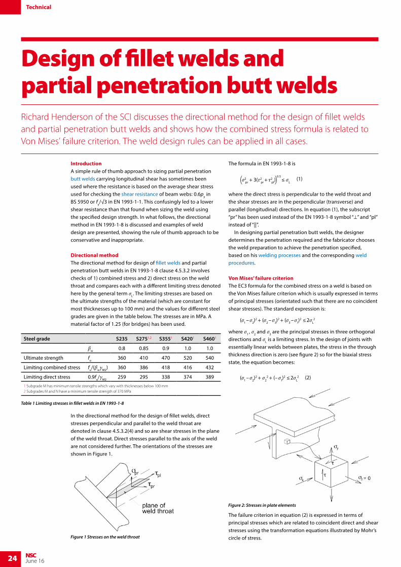
In the directional method for the design of fillet welds, direct stresses perpendicular and parallel to the weld throat are denoted in clause 4.5.3.2(4) and so are shear stresses in the plane of the weld throat. Direct stresses parallel to the axis of the weld are not considered further. The orientations of the stresses are shown in Figure 1.
The formula in EN 1993-1-8 is
σ2pr + 3(τ2
pr + τ2pl)
≤ σL( )0.5 (1)
where the direct stress is perpendicular to the weld throat and the shear stresses are in the perpendicular (transverse) and parallel (longitudinal) directions. In equation (1), the subscript “pr” has been used instead of the EN 1993-1-8 symbol “⊥” and “pl” instead of “||”. In designing partial penetration butt welds, the designer determines the penetration required and the fabricator chooses the weld preparation to achieve the penetration specified, based on his welding processes and the corresponding weld procedures.
Von Mises’ failure criterionThe EC3 formula for the combined stress on a weld is based on the Von Mises failure criterion which is usually expressed in terms of principal stresses (orientated such that there are no coincident shear stresses). The standard expression is:
(σ1 – σ2)2 + (σ2 – σ3)
2 + (σ3 – σ1)2 ≤ 2σL
2
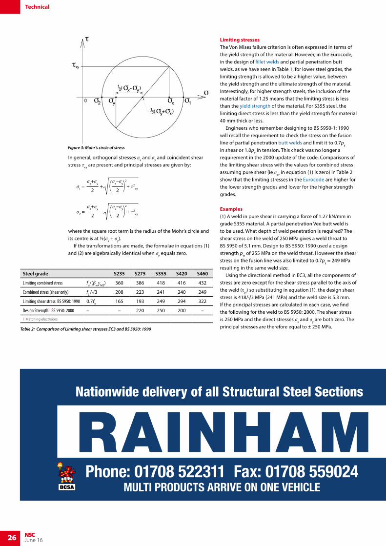
where σ1 , σ2 and σ3 are the principal stresses in three orthogonal directions and σL is a limiting stress. In the design of joints with essentially linear welds between plates, the stress in the through thickness direction is zero (see figure 2) so for the biaxial stress state, the equation becomes: (σ1 – σ2)
2 + σ22 + (– σ1)
2 ≤ 2σL2 (2)
The failure criterion in equation (2) is expressed in terms of principal stresses which are related to coincident direct and shear stresses using the transformation equations illustrated by Mohr’s circle of stress.
Design of fillet welds and partial penetration butt weldsRichard Henderson of the SCI discusses the directional method for the design of fillet welds and partial penetration butt welds and shows how the combined stress formula is related to Von Mises’ failure criterion. The weld design rules can be applied in all cases.
Table 1 Limiting stresses in fillet welds in EN 1993-1-8
Steel grade S235 S2751,2 S3551 S4201 S4601
βw 0.8 0.85 0.9 1.0 1.0
Ultimate strength fu 360 410 470 520 540
Limiting combined stress fu/(βwγM2) 360 386 418 416 432
Limiting direct stress 0.9fu/γM2 259 295 338 374 389
1 Subgrade M has minimum tensile strengths which vary with thicknesses below 100 mm2 Subgrades M and N have a minimum tensile strength of 370 MPa
Figure 1 Stresses on the weld throat
Figure 2: Stresses in plate elements
Purchase your copy:@SCIsteel
steel-construction-institute
SCI Shop: http://shop.steel-sci.com/Email: [email protected] | Telephone: 01344 636505
NEW SCI PUBLICATION
www.steel-sci.com
Thermal Bridging in Light Steel Framing & Modular Construction (P411)
Buildings account for nearly half of the UK’s total carbon emissions and heat losses through the building envelope account for more than 75% of the total heat loss including air leakage.
In response to the Energy Performance of Buildings Directive and the UK Climate Change Act 2008, national regulations are requiring ever more energy efficient buildings.
SCI’s newest publication illustrates various cases of thermal bridging and how local heat losses can be reduced. It describes the results of thermal modelling analyses of typical interface details used in light steel framing and modular construction.
This publication focusses on thermal bridging at junction details and balcony support attachments. The information may be used as general guidance on how to minimise thermal bridging in light steel framing and modular construction.
Complimentary publications include; P402 Light Steel Framing in Residential ConstructionP410 Thermal Bridging in Steel ConstructionED019 Thermal Performance of Light Steel Construction
Publication costs;SCI Members - £20.00Non Members - £40.00
26 NSCJune 16
In general, orthogonal stresses σx and σy and coincident shear stress τxy are present and principal stresses are given by:
σ1 = + τ2xy
σx+σy
2+
σx–σy
2( )2
σ2 = + τ2
xy
σx+σy
2–
σx–σy
2( )2
where the square root term is the radius of the Mohr’s circle and its centre is at ½(σx + σy). If the transformations are made, the formulae in equations (1) and (2) are algebraically identical when σy equals zero.
Limiting stressesThe Von Mises failure criterion is often expressed in terms of the yield strength of the material. However, in the Eurocode, in the design of fillet welds and partial penetration butt welds, as we have seen in Table 1, for lower steel grades, the limiting strength is allowed to be a higher value, between the yield strength and the ultimate strength of the material. Interestingly, for higher strength steels, the inclusion of the material factor of 1.25 means that the limiting stress is less than the yield strength of the material. For S355 steel, the limiting direct stress is less than the yield strength for material 40 mm thick or less. Engineers who remember designing to BS 5950-1: 1990 will recall the requirement to check the stress on the fusion line of partial penetration butt welds and limit it to 0.7py in shear or 1.0py in tension. This check was no longer a requirement in the 2000 update of the code. Comparisons of the limiting shear stress with the values for combined stress assuming pure shear (ie σpr in equation (1) is zero) in Table 2 show that the limiting stresses in the Eurocode are higher for the lower strength grades and lower for the higher strength grades.
Examples(1) A weld in pure shear is carrying a force of 1.27 kN/mm in grade S355 material. A partial penetration Vee butt weld is to be used. What depth of weld penetration is required? The shear stress on the weld of 250 MPa gives a weld throat to BS 5950 of 5.1 mm. Design to BS 5950: 1990 used a design strength pw of 255 MPa on the weld throat. However the shear stress on the fusion line was also limited to 0.7py = 249 MPa resulting in the same weld size. Using the directional method in EC3, all the components of stress are zero except for the shear stress parallel to the axis of the weld (τpl) so substituting in equation (1), the design shear stress is 418/√3 MPa (241 MPa) and the weld size is 5.3 mm.If the principal stresses are calculated in each case, we find the following for the weld to BS 5950: 2000. The shear stress is 250 MPa and the direct stresses σx and σy are both zero. The principal stresses are therefore equal to ± 250 MPa.
Technical
Table 2: Comparison of Limiting shear stresses EC3 and BS 5950: 1990
Figure 7: LTBeam software – stabilising load
RAINHAM STEELNationwide delivery of all Structural Steel Sections
Phone: 01708 522311 Fax: 01708 559024MULTI PRODUCTS ARRIVE ON ONE VEHICLE
GRADES S355JR/J0/J2
Head Office: 01708 522311 Fax: 01708 559024 Bury Office: 01617 962889 Fax: 01617 962921email: [email protected] www.rainhamsteel.co.uk
Beams • ColumnsChannel • AngleFlats • Uni Flats
Saw CuttingShot Blasting
Painting • DrillingHot & Cold Structural
Hollow Sections
RAINHAM STEEL Proud sponsors of BOXNATION Channel of Champions
Figure 3: Mohr’s circle of stress
Steel grade S235 S275 S355 S420 S460
Limiting combined stress fu/(βwγM2) 360 386 418 416 432
Combined stress (shear only) fL /√3 208 223 241 240 249
Limiting shear stress: BS 5950: 1990 0.7fy 165 193 249 294 322
Design Strength1: BS 5950: 2000 – – 220 250 200 –
1 Matching electrodes
27NSCJune 16
Substituting in equation (2) for the failure criterion, the limiting stress is 250 x √3 = 433 MPa. This is higher than 418 MPa, the limiting stress to EC3, where the principal stresses are ± 241 MPa.
(2) A second example of welds in pure shear is a lap joint transferring tension between plates in S355 material 20 mm thick, through longitudinal welds. It will be assumed that the edges of the plate are to be prepared for a partial penetration Vee butt weld. The thickness of the plates and length of the welds is such that it is assumed the direct stresses due to the eccentricity moment can be neglected.
1200 kN is to be transferred through welds on each edge of the plate with an effective length of 400 mm. The longitudinal shear stress per mm of weld is 1200 / (2 x 400) = 1.5 kN/mm. The penetration required is 1.5 × 10³ × √3/418 = 6.2 mm.
The size of weld throat to BS 5950: 2000 would be 1.5 x 10³ / 250 = 6.0 mm.
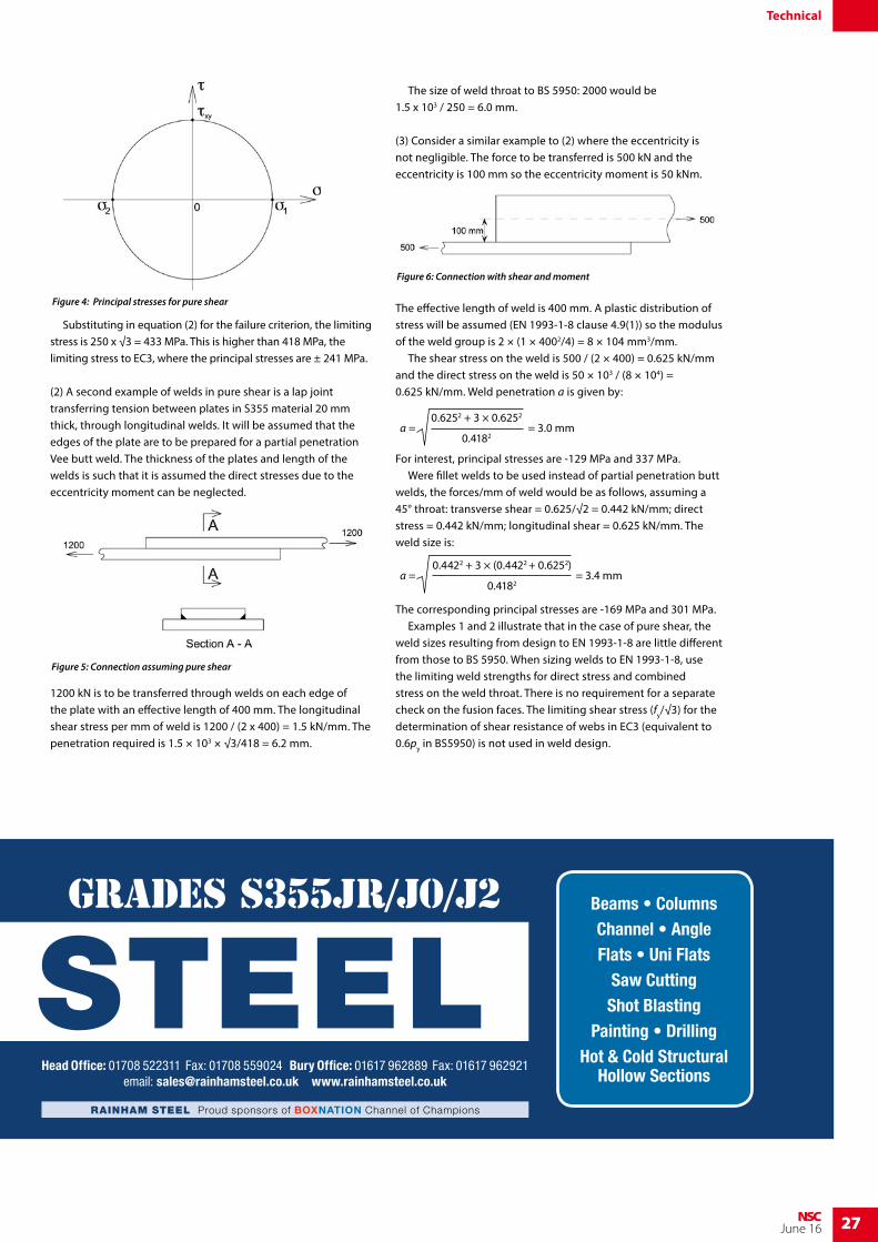
(3) Consider a similar example to (2) where the eccentricity is not negligible. The force to be transferred is 500 kN and the eccentricity is 100 mm so the eccentricity moment is 50 kNm.
The effective length of weld is 400 mm. A plastic distribution of stress will be assumed (EN 1993-1-8 clause 4.9(1)) so the modulus of the weld group is 2 × (1 × 4002/4) = 8 × 104 mm3/mm. The shear stress on the weld is 500 / (2 × 400) = 0.625 kN/mm and the direct stress on the weld is 50 × 103 / (8 × 10⁴) = 0.625 kN/mm. Weld penetration a is given by:
= 3.0 mma = 0.6252 + 3 × 0.6252
0.4182
For interest, principal stresses are -129 MPa and 337 MPa. Were fillet welds to be used instead of partial penetration butt welds, the forces/mm of weld would be as follows, assuming a 45° throat: transverse shear = 0.625/√2 = 0.442 kN/mm; direct stress = 0.442 kN/mm; longitudinal shear = 0.625 kN/mm. The weld size is:
= 3.4 mma = 0.4422 + 3 × (0.4422 + 0.6252)
0.4182
The corresponding principal stresses are -169 MPa and 301 MPa. Examples 1 and 2 illustrate that in the case of pure shear, the weld sizes resulting from design to EN 1993-1-8 are little different from those to BS 5950. When sizing welds to EN 1993-1-8, use the limiting weld strengths for direct stress and combined stress on the weld throat. There is no requirement for a separate check on the fusion faces. The limiting shear stress (fy/√3) for the determination of shear resistance of webs in EC3 (equivalent to 0.6py in BS5950) is not used in weld design.
Technical
RAINHAM STEELNationwide delivery of all Structural Steel Sections
Phone: 01708 522311 Fax: 01708 559024MULTI PRODUCTS ARRIVE ON ONE VEHICLE
GRADES S355JR/J0/J2
Head Office: 01708 522311 Fax: 01708 559024 Bury Office: 01617 962889 Fax: 01617 962921email: [email protected] www.rainhamsteel.co.uk
Beams • ColumnsChannel • AngleFlats • Uni Flats
Saw CuttingShot Blasting
Painting • DrillingHot & Cold Structural
Hollow Sections
RAINHAM STEEL Proud sponsors of BOXNATION Channel of Champions
Figure 4: Principal stresses for pure shear
Figure 5: Connection assuming pure shear
Figure 6: Connection with shear and moment