Embed Size (px)
Citation preview

DD CEN/TS1992-4-1:2009
ICS 21.060.01; 91.080.40
NO COPYING WITHOUT BSI PERMISSION EXCEPT AS PERMITTED BY COPYRIGHT LAW
DRAFT FOR DEVELOPMENT
Design of fasteningsfor use in concretePart 4-1: General

This Draft for Developmentwas published under theauthority of the StandardsPolicy and StrategyCommittee on 30 June2009.© BSI 2009
ISBN 978 0 580 62635 7
Amendments/corrigenda issued since publication
Date Comments
DD CEN/TS 1992-4-1:2009
National foreword
This Draft for Development is the UK implementation of CEN/TS1992-4-1:2009.This publication is not to be regarded as a British Standard.It is being issued in the Draft for Development series of publications andis of a provisional nature. It should be applied on this provisional basis,so that information and experience of its practical application can beobtained.Comments arising from the use of this Draft for Development arerequested so that UK experience can be reported to the internationalorganization responsible for its conversion to an international standard.A review of this publication will be initiated not later than 3 years afterits publication by the international organization so that a decision can betaken on its status. Notification of the start of the review period will bemade in an announcement in the appropriate issue of Update Standards.
According to the replies received by the end of the review period,the responsible BSI Committee will decide whether to support theconversion into an international Standard, to extend the life of theTechnical Specification or to withdraw it. Comments should be sent tothe Secretary of the responsible BSI Technical Committee at BritishStandards House, 389 Chiswick High Road, London W4 4AL.The UK participation in its preparation was entrusted to TechnicalCommittee B/525/2, Structural use of concrete.A list of organizations represented on this committee can be obtained onrequest to its secretary.This publication does not purport to include all the necessary provisionsof a contract. Users are responsible for its correct application.Compliance with a British Standard cannot confer immunityfrom legal obligations.
DD CEN/TS 1992-4-1:2009
TECHNICAL SPECIFICATION
SPÉCIFICATION TECHNIQUE
TECHNISCHE SPEZIFIKATION
CEN/TS 1992-4-1
May 2009
ICS 21.060.01; 91.080.40
English Version
Design of fastenings for use in concrete - Part 4-1: General
Conception-calcul des éléments de fixation pour béton -Partie 4-1: Généralités
Bemessung von Befestigungen in Beton - Teil 4-1:Allgemeines
This Technical Specification (CEN/TS) was approved by CEN on 20 October 2008 for provisional application.
The period of validity of this CEN/TS is limited initially to three years. After two years the members of CEN will be requested to submit theircomments, particularly on the question whether the CEN/TS can be converted into a European Standard.
CEN members are required to announce the existence of this CEN/TS in the same way as for an EN and to make the CEN/TS availablepromptly at national level in an appropriate form. It is permissible to keep conflicting national standards in force (in parallel to the CEN/TS)until the final decision about the possible conversion of the CEN/TS into an EN is reached.
CEN members are the national standards bodies of Austria, Belgium, Bulgaria, Cyprus, Czech Republic, Denmark, Estonia, Finland,France, Germany, Greece, Hungary, Iceland, Ireland, Italy, Latvia, Lithuania, Luxembourg, Malta, Netherlands, Norway, Poland, Portugal,Romania, Slovakia, Slovenia, Spain, Sweden, Switzerland and United Kingdom.
EUROPEAN COMMITTEE FOR STANDARDIZATIONC O M I T É E U R O P É E N D E N O R M A LI S A T I O NEUR OP ÄIS C HES KOM ITEE FÜR NOR M UNG
Management Centre: Avenue Marnix 17, B-1000 Brussels
© 2009 CEN All rights of exploitation in any form and by any means reservedworldwide for CEN national Members.
Ref. No. CEN/TS 1992-4-1:2009: E

DD CEN/TS 1992-4-1:2009CEN/TS 1992-4-1:2009 (E)
2
Contents
Page
Foreword ..............................................................................................................................................................4
1 Scope ......................................................................................................................................................61.1 General ....................................................................................................................................................61.2 Type of fasteners and fastening groups .............................................................................................61.3 Fastener dimensions and materials.....................................................................................................81.4 Fastener loading ....................................................................................................................................91.4.1 Type of loading ......................................................................................................................................91.4.2 Direction of loading ...............................................................................................................................91.5 Concrete strength ..................................................................................................................................91.6 Concrete member loading ................................................................................................................. 10
2 Normative references ......................................................................................................................... 10
3 Definitions and symbols .................................................................................................................... 113.1 Definitions ........................................................................................................................................... 113.2 Notations ............................................................................................................................................. 163.2.1 Indices .................................................................................................................................................. 163.2.2 Actions and Resistances ................................................................................................................... 173.2.3 Concrete and steel .............................................................................................................................. 183.2.4 Units ..................................................................................................................................................... 20
4 Basis of design ................................................................................................................................... 214.1 General ................................................................................................................................................. 214.2 Required verifications ........................................................................................................................ 214.3 Design format ...................................................................................................................................... 224.4 Verification by the partial factor method .......................................................................................... 234.4.1 General ................................................................................................................................................. 234.4.2 Partial factors for indirect and fatigue actions ................................................................................ 234.4.3 Partial factors for resistance ............................................................................................................. 234.5 Project specification and installation of fasteners .......................................................................... 25
5 Determination of concrete condition and action effects ................................................................ 265.1 Non-cracked and cracked concrete .................................................................................................. 265.2 Derivation of forces acting on fasteners .......................................................................................... 265.2.1 General ................................................................................................................................................. 265.2.2 Tension loads ...................................................................................................................................... 275.2.3 Shear loads .......................................................................................................................................... 30
6 Verification of ultimate limit state ..................................................................................................... 376.1 General ................................................................................................................................................. 37
7 Verification of fatigue limit state ....................................................................................................... 387.1 General ................................................................................................................................................. 387.2 Derivation of loads acting on fasteners ........................................................................................... 397.3 Resistance ........................................................................................................................................... 40
8 Verification for seismic loading ........................................................................................................ 428.1 General ................................................................................................................................................. 428.2 Requirements ...................................................................................................................................... 428.3 Actions ................................................................................................................................................. 428.4 Resistance ........................................................................................................................................... 42
9 Verification of serviceability limit state ............................................................................................ 45
Annex A (normative) Local transmission of fastener loads into the concrete member ........................... 46A.1 General ................................................................................................................................................. 46A.2 Verification of the shear resistance of the concrete member ........................................................ 46A.3 Verification of the resistance to splitting forces ............................................................................. 47

DD CEN/TS 1992-4-1:2009CEN/TS 1992-4-1:2009 (E)
3
Annex B (normative) Plastic design approach, fastenings with headed fasteners and post-installed fasteners ............................................................................................................................... 48
B.1 Field of application .............................................................................................................................. 48B.2 Loads on fastenings ............................................................................................................................ 50B.3 Design of fastenings ........................................................................................................................... 52B.3.1 Partial factors ....................................................................................................................................... 52B.3.2 Resistance to tension load ................................................................................................................. 52B.3.3 Resistance to shear load .................................................................................................................... 54
Annex C (informative) Durability ..................................................................................................................... 56C.1 General ................................................................................................................................................. 56C.2 Fasteners in dry, internal conditions ................................................................................................ 56C.3 Fasteners in external atmospheric or in permanently damp internal exposure ........................... 56C.4 Fasteners in high corrosion exposure by chloride and sulphur dioxide ...................................... 56
Annex D (informative) Exposure to fire – design method ............................................................................. 57D.1 General ................................................................................................................................................. 57D.2 Partial factors ....................................................................................................................................... 57D.3 Resistance under fire exposure ......................................................................................................... 57D.3.1 General ................................................................................................................................................. 57D.3.2 Tension load ........................................................................................................................................ 57D.3.3 Shear load ............................................................................................................................................ 59D.3.4 Combined tension and shear load ..................................................................................................... 60
Annex E (informative) Recommended additions and alterations to EN 1998-1:2004, 4.3.5 (Design of structures for earthquake resistance) for the design of fastenings under seismic loading .................................................................................................................................................. 61
E.1 General ................................................................................................................................................. 61E.2 Additions to Section 4.3.5.1 of EN 1998-1:2004 ............................................................................... 61E.3 Additions and alterations to EN 1998-1:2004, 4.3.5.2 ...................................................................... 61E.4 Additions to EN 1998-1:2004, 4.3.5.3 ................................................................................................. 63E.5 Additions and alterations to EN 1998-1:2004, 4.3.5.4 ...................................................................... 63
DD CEN/TS 1992-4-1:2009CEN/TS 1992-4-1:2009 (E)
4
Foreword
This document (CEN/TS 1992-4-1:2009) has been prepared by Technical Committee CEN/TC 250 “Structural Eurocodes”, the secretariat of which is held by BSI.
Attention is drawn to the possibility that some of the elements of this document may be the subject of patent rights. CEN [and/or CENELEC] shall not be held responsible for identifying any or all such patent rights.
This Technical Specification CEN/TS 1992-4-1 — General, describes the general principles and requirements for safety, serviceability and durability of fasteners for use in concrete, together with specific requirements for structures serving as base material for the fasteners. It is based on the limit state concept used in conjunction with a partial factor method.
The numerical values for partial factors and other reliability parameters are recommended values and may be changed in a National Annex, if required. The recommended values apply when:
a) the fasteners comply with the requirements of 1.2.2, and
b) the installation complies with the requirements of 4.5.
CEN/TS 1992-4 'Design of fastenings for use in concrete' is subdivided into the following parts:
Part 1: General
Part 2: Headed fasteners
Part 3: Anchor channels
Part 4: Post-installed fasteners — Mechanical systems
Part 5: Post-installed fasteners — Chemical systems
Part 1 is applicable to all products. Special rules applicable to particular products are given in Parts 2 to 5 of the series CEN/TS 1992-4. These Parts should be used only in conjunction with Part 1.
According to the CEN/CENELEC Internal Regulations, the national standards organizations of the following countries are bound to announce this Technical Specification: Austria, Belgium, Bulgaria, Cyprus, Czech Republic, Denmark, Estonia, Finland, France, Germany, Greece, Hungary, Iceland, Ireland, Italy, Latvia, Lithuania, Luxembourg, Malta, Netherlands, Norway, Poland, Portugal, Romania, Slovakia, Slovenia, Spain, Sweden, Switzerland and the United Kingdom.
National Annex for CEN/TS 1992-4-1
This CEN/TS gives values with notes indicating where national choices may have to be made. When this CEN/TS is made available at national level it may be followed by a National Annex containing all Nationally Determined Parameters to be used for the design of fastenings according to this CEN/TS for use in the relevant country.
National choice of the partial factors and reliability parameters is allowed in design according to this CEN/TS in the following clauses:
4.4.2;
4.4.3.1.1;

DD CEN/TS 1992-4-1:2009CEN/TS 1992-4-1:2009 (E)
5
4.4.3.1.2;
4.4.3.1.3;
4.4.3.2;
4.4.3.3;
5.1.2;
B.3.1;
D.2.
DD CEN/TS 1992-4-1:2009CEN/TS 1992-4-1:2009 (E)
6
1 Scope
1.1 General
1.1.1 This CEN/TS provides a design method for fasteners for structural purposes, which are used to transmit actions to the concrete.
Inserts embedded in precast concrete elements during production, under FPC conditions and with the due reinforcement, intended for use only during transient situations for lifting and handling, are covered by the CEN/TR “Design and Use of Inserts for Lifting and Handling Precast Concrete Elements”, by CEN TC 229.
1.1.2 This CEN/TS is intended for applications in which the failure of fastenings will:
1) result in collapse or partial collapse of the structure, or
2) cause risk to human life, or
3) lead to significant economic loss.
1.1.3 The support of the fixture may be either statically determinate or statically indeterminate, defined as multiple anchor use in some European Technical Approvals (ETAs). Each support may consist of one fastener or a group of fasteners.
1.1.4 This CEN/TS is valid for applications which fall within the scope of the series EN 1992. In applications where special considerations apply, e.g. nuclear power plants or civil defence structures, modifications may be necessary.
1.1.5 This CEN/TS does not cover the design of the fixture. The design of the fixture shall be carried out to comply with the appropriate Standards. Requirements for stiffness and ductility of the fixture are given in clauses 5 and 8.
1.2 Type of fasteners and fastening groups
1.2.1 This CEN/TS applies to:
a) cast-in fasteners such as headed fasteners, anchor channels with rigid connection between fastener and channel;
b) post-installed anchors such as expansion anchors, undercut anchors, concrete screws, bonded anchors, bonded expansion anchors and bonded undercut anchors.
For other types of fasteners modifications of the design provisions may be necessary.
1.2.2 This CEN/TS applies to fasteners with established suitability for the specified application in concrete covered by provisions, which refer to this CEN/TS and provide data required by this CEN/TS. The necessary data are listed in Parts 2 to 5.
NOTE Where there is no European Standard for a particular fastener which refers specifically to the use of this fastener or where the fastener deviates significantly from the European Standard, the establishment of suitability may result from:
a) European Technical Approval (ETA) which refers specifically to the use of the fastener in concrete;
b) relevant national standard or provision which refers specifically to the use of the fastener in concrete;
c) documentation of the fastener should include the characteristic resistance of the fastener and consider effects influencing the reliability of fasteners both during installation and in service life under sustained and variable loads, as well as the sensitivity to possible deviations on any of the factors of importance.

DD CEN/TS 1992-4-1:2009CEN/TS 1992-4-1:2009 (E)
7
d) Factors to be addressed are:
1) Installation conditions in concrete on site.
2) Drilling method and drill bit diameter in case of post-installed fasteners.
3) Bore hole cleaning.
4) Installation tools.
5) Sustained (long term) and variable loads on the fastener.
6) Variable loads on the concrete structure (crack cycling).
7) Crack width in the concrete structure.
8) Environmental conditions such as air pollution, alkalinity, aggressive environment, humidity, concrete- installation temperature, service temperature…
9) Location of fasteners in the concrete component.
10) Minimum dimensions of the structural component.
In addition to the assumptions of EN 1992-1-1 it is assumed that both the design and execution of fastening systems in concrete structures is carried out by personnel having the appropriate skill and experience.
1.2.3 This CEN/TS applies to single fasteners and groups of fasteners. In a fastening group the loads are applied to the individual fasteners of the group by means of a common fixture. In this CEN/TS it is assumed that in a fastening group only fasteners of the same type and size are used.
The configurations of fasteners (cast-in place headed fasteners and post-installed fasteners) covered by this CEN/TS are shown in Figure 1.
Distinction is to be made between fastenings with and without hole clearance.
The following applications may be considered to have no hole clearance:
a) bolts are welded to the fixture or screwed into the fixture, or
b) any gap between the fastener and the fixture is filled with mortar of sufficient compression strength or eliminated by other suitable means;
For anchor channels the number of fasteners is not limited.

DD CEN/TS 1992-4-1:2009CEN/TS 1992-4-1:2009 (E)
8
Key 1 Fastener 2 Steel plate
a) Fastenings without hole clearance, all edge distances b) Fastenings with hole clearance situated far from edges c) Fastenings with hole clearance situated near to an edge a c1 < 10 hef or c1 < 60 dnom b c2 < 10 hef or c2 < 60 dnom
Figure 1 — Configuration of fastenings with headed and post-installed fasteners
1.3 Fastener dimensions and materials
1.3.1 This CEN/TS applies to fasteners with a minimum diameter or a minimum thread size of 6 mm (M6) or a corresponding cross section. In general, the minimum embedment depth should be: hef ≥ 40 mm. The actual value for a particular fastener might be taken from the relevant European Technical Specification.
1.3.2 This CEN/TS covers metal fasteners made of either carbon steel (ISO 898), stainless steel (EN 10088, ISO 3506) or malleable cast iron (ISO 5922). The surface of the steel may be coated or uncoated. The fasteners may include non-load bearing material e.g. plastic parts. This document is valid for fasteners with a

DD CEN/TS 1992-4-1:2009CEN/TS 1992-4-1:2009 (E)
9
nominal steel tensile strength fuk ≤ 1000 N/mm². The binding material of bonded fasteners may be made primarily of resin, cement or a combination of the two. In addition inorganic fillers may be used.
1.4 Fastener loading
1.4.1 Type of loading
Loading on the fastenings may be static, cyclic (causing fatigue failure) and seismic. The suitability of the fastener type to resist either cyclic or seismic loading is stated in the relevant European Technical Specification.
1.4.2 Direction of loading
The loading on the fastener resulting from the actions on the fixture (e.g. tension, shear, bending or torsion moments or any combination thereof) will generally be axial tension and/or shear. When the shear force is applied with a lever arm a bending moment on the fastener will arise. Any axial compression on the fixture should be transmitted to the concrete either without acting on the fastener or via fasteners suitable for resisting compression (Figure 2).
Key 1 concrete
a), b) fasteners not loaded in compression; in Figure (a) the compression force is transferred by the fixture and in Figure (b) by the washer c) fasteners loaded in compression
Figure 2 — Examples of fastenings loaded by a bending moment and a compression force
1.5 Concrete strength
This document is valid for members using normal weight concrete with strength classes in the range C12/15 to C90/105 all in accordance with EN 206-1. The range of concrete strength classes in which particular fasteners may be used is given in the relevant European Technical Specification and may be more restrictive than stated above.

DD CEN/TS 1992-4-1:2009CEN/TS 1992-4-1:2009 (E)
10
1.6 Concrete member loading
If the concrete member is subjected to cyclic or seismic loading certain types of fasteners may not be allowed. This is stated in the corresponding European Technical Specification.
2 Normative references
This European Standard incorporates by dated or undated reference, provisions from other publications. These normative references are cited at the appropriate places in the text and the publications are listed hereafter. For dated references, subsequent amendments to or revisions of any of these publications apply to this European Standard only when incorporated in it by amendment or revision. For undated references the latest edition of the publication referred to applies.
NOTE The following references to Eurocodes are references to European Standards and European Prestandards. These are the only European documents available at the time of publication of this CEN/TS. National documents take precedence until Eurocodes are published as European Standards.
EN 206-1, Concrete — Part 1: Specification, performance, production and conformity
EN 1990:2002, Eurocode — Basis of structural design
EN 1992-1-1:2004, Eurocode 2: Design of concrete structures — Part 1-1: General rules and rules for buildings
EN 1993-1-1:2005, Eurocode 3: Design of steel structures — Part 1-1: General rules and rules for buildings
EN 1993-1-8:2005, Eurocode 3: Design of steel structures — Part 1-8: Design of joints
EN 1994-1-1:2004, Eurocode 4: Design of composite steel and concrete structures — Part 1-1: General rules and rules for buildings
EN 1998-1:2004, Eurocode 8: Design of structures for earthquake resistance — Part 1: General rules, seismic actions and rules for buildings
EN 10002-1, Metallic materials — Tensile testing — Part 1: Method of test at ambient temperature
EN 10080, Steel for the reinforcement of concrete — Weldable reinforcing steel — General
EN 10088-2: Stainless steels — Part 2: Technical delivery conditions for sheet/plate and strip of corrosion resisting steels for general purposes
EN 10088-3, Stainless steels — Part 3: Technical delivery conditions for semi-finished products, bars, rods, wire, sections and bright products of corrosion resisting steels for general purposes
EN 12390-2, Testing hardened concrete — Part 2: Making and curing specimens for strength tests
EN 12390-3, Testing hardened concrete — Part 3: Compressive strength of test specimens
EN 12390-7, Testing hardened concrete — Part 7: Density of hardened concrete
EN 12504-1, Testing concrete in structures — Part 1: Cored specimens — Taking, examining and testing in compression
EN 13501-2, Fire classification of construction products and building elements — Part 2: Classification using data from fire resistance tests, excluding ventilation services
EN ISO 13918, Welding — Studs and ceramic ferrules for arc stud welding (ISO 13918:2008)

DD CEN/TS 1992-4-1:2009CEN/TS 1992-4-1:2009 (E)
11
ISO 273, Fasteners — Clearance holes for bolts and screws
ISO 898-1, Mechanical properties of fasteners made of carbon steel and alloy steel — Part 1: Bolts, screws and studs
ISO 898-2, Mechanical properties of fasteners — Part 2: Nuts with specified proof load values — Coarse thread
ISO 1803:1997, Building construction — Tolerances — Expression of dimensional accuracy — Principles and terminology
ISO 3506, Mechanical properties of corrosion-resistant stainless-steel fasteners
ISO 5922, Malleable cast iron (Revision of ISO 5922:1981)
3 Definitions and symbols
3.1 Definitions
3.1.1 Anchor Element made of steel or malleable iron either cast into concrete or post-installed into a hardened concrete member and used to transmit applied loads (see Figures 3 to 5). In this CEN/TS 'anchor' and 'fastener' are used synonymously. In the case of anchor channels, a steel fastener is rigidly connected to the back of the channel and embedded in concrete
3.1.2 Anchor channel Steel profile with rigidly connected anchors (also called channel bar, see Figure 4) installed prior to concreting
3.1.3 Anchor channel loading: Axial tension Load applied perpendicular to the surface of the base material
3.1.4 Anchor channel loading: Bending Bending effect induced by a load applied perpendicular to the longitudinal axis of the channel
3.1.5 Anchor channel loading: Combined Axial and shear loading applied simultaneously (oblique loading)
3.1.6 Anchor channel loading: Shear Shear acting parallel to the concrete surface and transversely with respect to the longitudinal axis of the channel
3.1.7 Anchor group A number of fasteners with identical characteristics acting together to support a common attachment, where the spacing of the anchors does not exceed the characteristic spacing
3.1.8 Anchor loading: Axial Load applied perpendicular to the surface of the base material and parallel to the fastener longitudinal axis

DD CEN/TS 1992-4-1:2009CEN/TS 1992-4-1:2009 (E)
12
3.1.9 Anchor loading: Bending Bending effect induced by a shear load applied with an eccentricity with respect to the centroid of resistance
3.1.10 Anchor loading: Combined Axial and shear loading applied simultaneously (oblique loading)
3.1.11 Anchor loading: Shear Shear induced by a load applied perpendicular to the longitudinal axis of the fastener
3.1.12 Anchor spacing Distance between the centre lines of the fasteners
3.1.13 Anchorage component Component (element) in which a fastener is anchored
3.1.14 Attachment Metal assembly that transmits loads to the fastener. In this CEN/TS 'attachment' and 'fixture' are used synonymously
3.1.15 Base material Material in which the fastener is installed
3.1.16 Blow-out failure Spalling of the concrete on the side face of the anchorage component at the level of the embedded head with no major breakout at the top concrete surface. This is usually associated with anchors with small side cover and deep embedment
3.1.17 Bonded anchor Fastener placed into a hole in hardened concrete, which derives its resistance from a bonding compound placed between the wall of the hole in the concrete and the embedded portion of the fastening (see Figure 5g))
3.1.18 Bond failure Failure that occurs at the interface between the bonding compound and the base material or between the bonding compound and the metal part of a bonded anchor system
3.1.19 Bonded expansion anchor Bonded anchor designed such that the anchor bolt can move relative to the hardened bonding compound resulting in follow-up expansion (see Figure 5h))
3.1.20 Cast-in fastener Headed bolt, headed stud, hooked bolt or anchor channel installed before placing the concrete, see headed anchor
3.1.21 Characteristic spacing Spacing required to ensure the characteristic resistance of a single fastener
DD CEN/TS 1992-4-1:2009CEN/TS 1992-4-1:2009 (E)
13
3.1.22 Characteristic resistance The 5 % fractile of the resistance (value with a 95 % probability of being exceeded, with a confidence level of 90 %)
3.1.23 Clamping force Prestressing force resulting from tightening of the fastener against the fixture
3.1.24 Concrete breakout failure Failure that corresponds to a wedge or cone of concrete surrounding the fastener or group of fasteners separating from the base material
3.1.25 Concrete pry-out failure Failure that corresponds to the formation of a concrete spall opposite to the loading direction under shear loading
3.1.26 Concrete screw Threaded anchor screwed into a predrilled hole where threads create a mechanical interlock with the concrete (see Figure 5f))
3.1.27 Displacement Movement of the loaded end of the fastener relative to the concrete member into which it is installed in the direction of the applied load. In the case of anchor channels, movement of an anchor channel relative to the anchorage component. In tension tests, displacement is measured parallel to the anchor axis. In shear tests, displacement is measured perpendicular to the anchor axis
3.1.28 Deformation-controlled expansion anchor A post-installed fastener that derives its tensile resistance by expansion against the side of the drilled hole through movement of an internal plug in the sleeve (see Figures 5c)) or through movement of the sleeve over an expansion element (plug). Once set, no further expansion can occur
3.1.29 Ductile steel element An element with sufficient ductility. The ductility conditions are given in the relevant sections
3.1.30 Edge distance Distance from the edge of the concrete member to the centre of the fastener
3.1.31 Effective embedment depth The definition of the effective embedment depth for the different types of fasteners is given in Figures 3 to 5
3.1.32 European Technical Specification Harmonized European Product Standard (hEN) or European Technical Approval (ETA)
3.1.33 Fastener See anchor
3.1.34 Fastening Assembly of fixture and fasteners used to transmit loads to concrete

DD CEN/TS 1992-4-1:2009CEN/TS 1992-4-1:2009 (E)
14
3.1.35 Fixture See attachment
3.1.36 Headed anchor Steel fastener installed before placing concrete (see Figure 3). It derives its tensile resistance from mechanical interlock at the anchor head. The definitions given in Figure 3b) and 3c) should be verified for directions 1 and 2 according to Figure 6
3.1.37 Installation safety factor Partial factor that accounts for the sensitivity of a fastener to installation inaccuracies on its performance
3.1.38 Mechanical interlock Load transfer to a concrete member via interlocking surfaces
3.1.39 Minimum edge distance Minimum allowable edge distance to allow adequate placing and compaction of concrete (cast-in place fasteners) and to avoid damage to the concrete during installation (post-installed fasteners), given in the European Technical Specification
3.1.40 Minimum member thickness Minimum member thickness, in which a fastener can be installed, given in the European Technical Specification
3.1.41 Minimum spacing Minimum fastener spacing to allow adequate placing and compaction of concrete (cast-in fasteners) and to avoid damage to the concrete during installation (post-installed fasteners), measured centreline to centreline, given in the European Technical Specification
3.1.42 Post-installed fastener A fastener installed in hardened concrete (see Figure 5)
3.1.43 Pullout failure A failure mode in which the fastener pulls out of the concrete without development of the full concrete resistance or a failure mode in which the fastener body pulls through the expansion sleeve without development of the full concrete resistance
3.1.44 Special screw Screw which connects the element to be fixed to the anchor channel
3.1.45 Splitting failure A concrete failure mode in which the concrete fractures along a plane passing through the axis of the fastener or fasteners
3.1.46 Steel failure of fastener Failure mode characterised by fracture of the steel fastener parts
DD CEN/TS 1992-4-1:2009CEN/TS 1992-4-1:2009 (E)
15
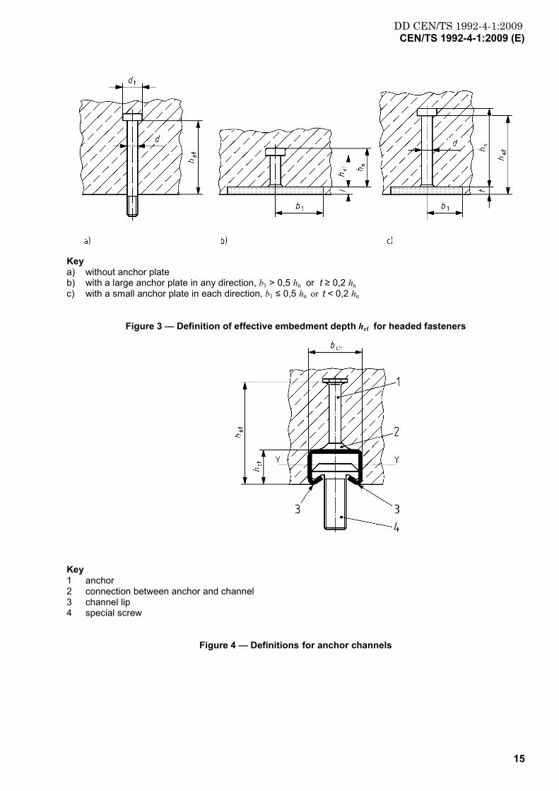
Key a) without anchor plate b) with a large anchor plate in any direction, b1 > 0,5 hn or t ≥ 0,2 hn c) with a small anchor plate in each direction, b1 ≤ 0,5 hn or t < 0,2 hn
Figure 3 — Definition of effective embedment depth hef for headed fasteners
Key 1 anchor 2 connection between anchor and channel 3 channel lip 4 special screw
Figure 4 — Definitions for anchor channels
DD CEN/TS 1992-4-1:2009CEN/TS 1992-4-1:2009 (E)
16
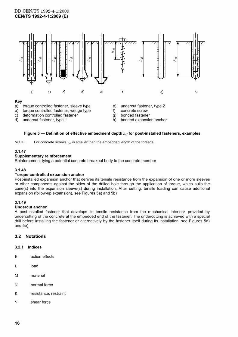
Key a) torque controlled fastener, sleeve type b) torque controlled fastener, wedge type c) deformation controlled fastener d) undercut fastener, type 1
e) undercut fastener, type 2 f) concrete screw g) bonded fastener h) bonded expansion anchor
Figure 5 — Definition of effective embedment depth hef for post-installed fasteners, examples
NOTE For concrete screws hef is smaller than the embedded length of the threads.
3.1.47 Supplementary reinforcement Reinforcement tying a potential concrete breakout body to the concrete member
3.1.48 Torque-controlled expansion anchor Post-installed expansion anchor that derives its tensile resistance from the expansion of one or more sleeves or other components against the sides of the drilled hole through the application of torque, which pulls the cone(s) into the expansion sleeve(s) during installation. After setting, tensile loading can cause additional expansion (follow-up expansion), see Figures 5a) and 5b)
3.1.49 Undercut anchor A post-installed fastener that develops its tensile resistance from the mechanical interlock provided by undercutting of the concrete at the embedded end of the fastener. The undercutting is achieved with a special drill before installing the fastener or alternatively by the fastener itself during its installation, see Figures 5d) and 5e)
3.2 Notations
3.2.1 Indices
E action effects
L load
M material
N normal force
R resistance, restraint
V shear force
DD CEN/TS 1992-4-1:2009CEN/TS 1992-4-1:2009 (E)
17
a acceleration
b bond
c concrete
ca connection
cb blow-out
cp concrete pryout
d design value
el elastic
eq seismic (earthquake)
fat fatigue
fi fire
fix fixture
flex bending
g load on or resistance of a group of fasteners
h highest loaded fastener in a group
k characteristic value
l local
max maximum
min minimum
nom nominal
p pull out
pl plastic
re reinforcement
s steel
sp splitting
u ultimate
y yield
0 basic value
3.2.2 Actions and Resistances
g gravity
F force in general
N normal force (positive = tension force, negative = compression force)

DD CEN/TS 1992-4-1:2009CEN/TS 1992-4-1:2009 (E)
18
V shear force
M moment
M1 bending moment on fixture around axis in direction 1
M2 bending moment on fixture around axis in direction 2
T torsional moment on fixture
)( RkRkRk V;NF characteristic value of resistance of a single fastener or a group respectively (normal force, shear force)
)( RdRdRd V;NF design value of resistance of a single fastener or a group respectively (normal force, shear force)
FEk (NEk; VEk; MEk; TEk) characteristic value of actions acting on the fixture (normal load, shear load, bending moment, torsion moment)
FEd (NEd; VEd; MEd; TEd) design value of actions acting on the fixture (normal load, shear load, bending moment, torsion moment), in the case of anchor channels design value of actions acting on the special screw
)( aEd
aEd
aEd V;NF design value of action on one anchor of the anchor channel
)( aiEd
aiEd
aiEd ,,, V;NF design value of action on anchor i of the anchor channel
)( hEd
hEd VN design value of tensile load (shear load) acting on the most stressed fastener of a group
)V(N gEd
gEd design value of the resultant tensile (shear) loads of the fasteners in a group effective in
taking up tension (shear) loads
reEd ,N design value of tension load acting on the supplementary reinforcement
areEd ,N design value of tension load acting on the supplementary reinforcement of one anchor
of the anchor channel
3.2.3 Concrete and steel
fcd design compressive strength of concrete
fck characteristic compressive strength of concrete (strength class) measured on cylinders 150 × 300 mm
fck,cube characteristic compressive strength of concrete (strength class) measured on cubes with a side length 150 mm
fyk characteristic steel yield strength or steel proof strength respectively (nominal value)
fuk characteristic steel ultimate tensile strength (nominal value)
A'i ordinate of a triangle with the height 1 at the position of the load NEd and the base length 2 li at the position of the anchors i of an anchor channel
DD CEN/TS 1992-4-1:2009CEN/TS 1992-4-1:2009 (E)
19
As stressed cross section of steel
Iy moment of inertia of the channel [mm4] relative to the y-axis (see Figure 4)
Wel elastic section modulus calculated from the stressed cross section of steel
3.2.3.1 Fasteners and fastenings
Notation and symbols frequently used in this CEN/TS are given below and are illustrated in Figures 3 to 6 and 15, 16, 18 and 19. Further notation and symbols are given in the text.
a1 (a2) spacing between outer fasteners in adjoining fastenings in direction 1 (direction 2) (see Figure 6)
a3 distance between concrete surface and point of assumed restraint of a fastener loaded by a shear force with lever arm (see Figure 15)
b width of concrete member
bch width of the channel, (see Figure 4)
bfix width of fixture
c edge distance from the axis of a fastener (see Figure 6) or the axis of a anchor channel
c1 edge distance in direction 1 (see Figure 6)
c2 edge distance in direction 2. Direction 2 is perpendicular to direction 1
ccr characteristic edge distance for ensuring the transmission of the characteristic resistance of a single fastener
cmin minimum allowable edge distance
d diameter of fastener bolt or thread diameter (Figure 12), diameter of the stud or shank of headed studs
df diameter of clearance hole in the fixture (Figure 12)
dh diameter of anchor head (headed anchor)
dnom outside diameter of a fastener (Figure 12)
ds diameter of reinforcing bar
d0 nominal diameter of drilled hole
e1 distance between shear load and concrete surface (see Figure 15)
es distance between the axis of the shear load and the axis of the supplementary reinforcement for shear
h thickness of concrete member in which the fastener is installed (see Figure 6)
hch height of the channel (see Figure 4)
hef effective embedment depth (see Figures 3 to 5). It is given in the corresponding European Technical Specification
hmin minimum allowed thickness of concrete member

DD CEN/TS 1992-4-1:2009CEN/TS 1992-4-1:2009 (E)
20
l lever arm of the shear force acting on a fastener (Figure 15)
li influence length of an external load NEd along an anchor channel
n number of fasteners in a group
s centre to centre spacing of fasteners in a group (see Figure 6) or spacing of reinforcing bars
s1 (s2) spacing of fasteners in a group in direction 1 (direction 2) (see Figure 6)
scr characteristic spacing for ensuring the transmission of the characteristic resistance of a single fastener
smin minimum allowable spacing
t time
tgrout thickness of grout layer (see Figure 16)
tfix thickness of fixture
Key
1 indices 1 and 2 depend on the direction of the shear load (1: in direction of shear load; 2: perpendicular to direction of shear load)
a) fastenings subjected to tension load b) fastenings subjected to shear load in the case of fastening near an edge
Figure 6 — Definitions related to concrete member dimensions, fastener spacing and edge distance
3.2.4 Units
In this CEN/TS SI-units are used. Unless stated otherwise in the equations, the following units are used: Dimensions are given in mm, cross sections in mm2, section modulus in mm3, forces and loads in N and stresses in N/mm².

DD CEN/TS 1992-4-1:2009CEN/TS 1992-4-1:2009 (E)
21
4 Basis of design
4.1 General
4.1.1 With appropriate degrees of reliability fasteners shall sustain all actions and influences likely to occur during execution and use (ultimate limit state). They shall not deform to an inadmissible degree (serviceability limit state) and remain fit for the use for which they are required (durability). They shall not be damaged by accidental events to an extent disproportional to the original cause.
4.1.2 Fastenings shall be designed according to the same principles and requirements valid for structures given in EN 1990 including load combinations.
NOTE A design using the partial factors given in this CEN/TS and the partial factors given in the EN 1990 Annexes is considered to lead to a structure associated with reliability class RC2, i.e. a ß-value of 3,8 for a 50 year reference period. For further information, see EN 1990 Annexes B and C.
4.1.3 The design working life of the fasteners shall not be less than that of the fixture.
The safety factors for resistance and durability in this CEN/TS are based on a nominal working life of at least 50 years for the fastening.
4.1.4 Actions shall be obtained from the relevant parts of EN 1991 or EN 1998, in the case of seismic actions, see also Annex E of this CEN/TS.
4.1.5 If the fastening is subjected to fatigue or seismic actions only, fasteners suitable for this application shall be used (see relevant European Technical Specification).
4.1.6 The transfer of the loads acting on the fixture to the supports of the structure shall be considered in the design of the structure taking account of the requirements of Annex A.
4.1.7 For the design and execution of fastenings the same quality requirements are valid as for the design and execution of structures and the attachment:
The design of the fastening shall be performed by qualified personnel.
The fastenings shall be installed according to project specifications.
4.1.8 The execution should comply with 4.5.
4.2 Required verifications
4.2.1 For the fasteners the following limit states should be verified:
ultimate limit state, including effects of fatigue and seismic loading, where appropriate;
serviceability limit state.
Furthermore the durability of the fastening for the intended use should be demonstrated.
Information is given in Informative Annex C.
4.2.2 In the ultimate limit state, verifications are required for all appropriate load directions and all relevant failure modes.
4.2.3 In the serviceability limit state, it shall be shown that the displacements occurring under the relevant actions are not larger than the admissible displacement.
4.2.4 The material of the fastener and the corrosion protection should be selected taking into account:
a) environmental conditions at the place of installation; and
b) if the fasteners are inspectable, maintainable and replaceable.
DD CEN/TS 1992-4-1:2009CEN/TS 1992-4-1:2009 (E)
22
4.2.5 Where applicable the fastening should have an adequate fire resistance. For the purpose of this CEN/TS it is assumed that the fire resistance of the fixture is adequate.
Verification of the fire resistance should be based on the principles in fire parts of the Eurocodes, EN 1992-1-2 for concrete and EN 1993-1-2 for steel, or by testing taking into account fastener specific conditions. Fire resistance may be expressed as standard fire resistance (R classification) or resistance to parametric fire, see EN 1991-1-2. Information on a design method is also given in Informative Annex D.
NOTE Where there is no European Standard for a particular fastener under fire exposure which refers specifically to the use of this fastener or where the fastener or its fire exposure deviates significantly from the European Standard, the establishment of fire resistance may result from:
The EOTA Technical Report 'Evaluation of Anchorages in Concrete concerning Resistance to Fire' which refers specifically to the use of the fastener in concrete under fire exposure;
a relevant national standard or provision which refers specifically to the use of the fastener in concrete under fire exposure.
4.3 Design format
4.3.1 At the ultimate limit state and the limit state of fatigue it shall be shown that.
dd RE ≤ (1)
Ed design value of effect of actions
Rd design value of resistance
At the serviceability limit it shall be shown that
dd CE ≤ (2)
Ed design value of fastener displacement
Cd nominal value, e.g. limiting displacement
4.3.2 The forces in the fasteners should be derived using appropriate combinations of actions on the fixture as recommended in EN 1990:2002, Section 6. When indirect action Qind arises from the restraint to the deformation of the fastened member (fixture, attachment), the design action shall be taken as γind ·Qind.
Forces resulting from restraint to deformation, intrinsic (e.g. shrinkage) or extrinsic (e.g. temperature variations) of the attached member should be taken into account in the design of fasteners.
4.3.3 In general actions in the fixture may be calculated ignoring the displacement of the fasteners. However, the effect of the displacement of the fasteners may be significant when a statically indeterminate stiff element is fastened and should be considered in these cases.
4.3.4 In the ultimate limit state, the value of the design resistance is obtained from the characteristic resistance of the fastener or the group of fasteners respectively as follows:
Mkd γRR /= (3)
where
Rk characteristic resistance of single fastener or group of fasteners
γM partial factor for resistance
4.3.5 In the serviceability limit state, the value Ed which is the design value of fastener displacement shall be evaluated from the information given in the relevant European Technical Specification, for Cd see Section 9.2.
DD CEN/TS 1992-4-1:2009CEN/TS 1992-4-1:2009 (E)
23
4.4 Verification by the partial factor method
4.4.1 General
Partial factors to be used are stated in EN 1990, Annex A.
4.4.2 Partial factors for indirect and fatigue actions
For the verification of indirect (ultimate limit state) and fatigue actions the values of the partial factors γind and γF,fat should be used.
NOTE The values of γind and γF,fat for use in a Country may be found in its National Annex. The recommended values are γind = 1,2 for concrete failure and γind = 1,0 for other modes of failure, and in case of fatigue loading γF,fat = 1,0.
4.4.3 Partial factors for resistance
4.4.3.1 Ultimate limit state (static and seismic loading)
4.4.3.1.1 Partial factors for steel
The partial factors for steel are γ Ms, γ Ms,ca, γ Ms,.l, γ Ms,flex and γ Ms,re.
NOTE The value for use in a Country may be found in its National Annex. The recommended values are given in Equations (4) to (10). They take into account that the characteristic resistance is based on fuk, except fyk should be used for bending of the channel of anchor channels and steel failure of supplementary reinforcement.
Tension loading on fasteners, anchors and special screws of anchor channels:
1,4/1,2 ≥⋅= ykukMs ffγ (4)
Shear loading on fasteners and special screws of anchor channels with and without a lever arm:
1,251,0 ≥⋅= ykukMs f/fγ 0,8andN/mm800 2 ≤≤ ukykuk f/ff (5)
1,5=Msγ 0,8orN/mm800 2 >> ukykuk f/ff (6)
Connection between anchor and channel of anchor channels:
1,8, =caMsγ (7)
Local failure of the anchor channel by bending of the lips in tension and shear:
1,8=lMs,γ (8)
Bending of the channel of anchor channels:
1,15=flexMs,γ (9)
Steel failure of supplementary reinforcement:
1,15=reMs,γ (10)
4.4.3.1.2 Partial factor for concrete
The partial factor γMc covers concrete break-out failure modes (cone failure, blow-out failure, pry-out failure and edge failure), the partial factor γMsp covers splitting failure.
The value for γMc is determined from:

DD CEN/TS 1992-4-1:2009CEN/TS 1992-4-1:2009 (E)
24
instcMc γγγ ⋅= (11)
where
γ c partial factor for concrete under compression
The partial factor γc for use in a country may be found in its National Annex. The recommended value is γc = 1,5
γ ins partial factor taking into account installation safety of the fastening system.
γ ins is given in the European Technical Specification.
For post-installed fasteners the following values γ inst are given for information:
Tension loading:
γ inst = 1,0 for systems with high installation safety = 1,2 for systems with normal installation safety = 1,4 for systems with low but still acceptable installation safety
Shear loading:
γ inst = 1,0
For cast-in place fasteners then if the conditions of 4.5 and of EN 1992-1-2:2004, 4.5.5 are fulfilled high installation safety may be assumed for all load directions and
γ inst = 1,0
For anchor channels, then if the conditions of 4.5 and ENV 1992-1-3:1994, Section 4.5.4 are fulfilled high installation safety may be assumed for all load directions and
γ inst = 1,0
However, for seismic strengthening and repair of existing structures the partial factor for concrete γc in Equation (11) may be reduced according to the relevant clauses of EN 1998.
NOTE The value of γMsp for use in a country may be found in its National Annex. For the partial factor of γMsp the value for γMc is recommended.
4.4.3.1.3 Partial factor for pull-out failure
The partial factor for pull-out failure is γMp.
NOTE The value γMp for use in a Country may be found in its National Annex. For the partial factor γMp the value for γMc is recommended.
4.4.3.2 Limit state of fatigue
Partial factors for fatigue loading γMs,fat, γMc,fat, γMsp,fat and γMp,fat shall be considered.
NOTE The values of the partial factors for fastenings under fatigue loading for use in a country may be found in its National Annex. It is recommended to take the partial factor for material as γMs,fat =1,35 (steel failure), γMc,fat = γMsp,fat = γMp,fat (concrete cone failure, splitting failure and pullout failure) according to Equation (4-10).

DD CEN/TS 1992-4-1:2009CEN/TS 1992-4-1:2009 (E)
25
4.4.3.3 Partial factors in the serviceability limit state
The partial factor for resistance is γM.
NOTE The value of the partial factor for serviceability limit state for use in a Country may be found in its National Annex. For the partial factor γM the value γM = 1,0 is recommended.
4.5 Project specification and installation of fasteners
4.5.1 The resistance and reliability of fastenings are significantly influenced by the manner in which the fasteners are installed. The partial factors given in 4.4 are valid only when the following conditions and the conditions given in 4.5.4 of the product-specific Parts 2, 3, 4 and 5 of this CEN/TS are fulfilled:
a) The installation instructions and all necessary information for correct installation shall be available on site or in the precast plant at the time the installation takes place. The installation instructions for the fastener, which are normally given in the European Technical Specification shall be followed.
b) Gross errors on site shall be avoided by the use of trained personnel and adequate supervision.
4.5.2 The project specification shall typically include the following:
1) Strength class of the concrete used in the design and indication as to whether the concrete is assumed to be cracked or not cracked.
NOTE If non-cracked concrete is assumed, verification is required (see 5.1.2).
2) Environmental exposure, assumed in design (EN 206-1).
3) A note indicating that the number, manufacturer, type and geometry of the fasteners should not be changed without reference to the original design.
4) Construction drawings, which should include
location of the fasteners in the structure, including tolerances;
number and type of fasteners (including embedment depth);
spacing and edge distance of the fastenings including tolerances. Normally these should be specified with positive tolerances only.
thickness of fixture and diameter of the clearance holes (if applicable);
position of the attachment on the fixture including tolerances;
maximum thickness of an eventual intervening layer e.g. grout or insulation between the fixture and surface of the concrete;
(special) installation instructions (if applicable).
5) Reference to the manufacturer's installation instructions.
6) A note that the fasteners shall be installed ensuring not less than the specified embedment depth.
Additional product specific items are given in the relevant parts of this CEN/TS.
4.5.3 If the conditions in this Section are complied with, no proof testing of the fasteners is necessary.

DD CEN/TS 1992-4-1:2009CEN/TS 1992-4-1:2009 (E)
26
5 Determination of concrete condition and action effects
5.1 Non-cracked and cracked concrete
5.1.1 In the region of the fastening, the concrete may be cracked or non-cracked. The condition of the concrete should be determined by the designer.
NOTE In general, it is always conservative to assume that the concrete is cracked.
5.1.2 Non-cracked concrete may be assumed if it is proven that under service conditions the fastener with its entire embedment depth is located in non-cracked concrete. This will be satisfied if Equation (12) is observed (compressive stresses are negative):
admRL σσσ ≤+ (12)
Lσ stresses in the concrete induced by external loads including fastener loads
Rσ stresses in the concrete due to restraint of intrinsic imposed deformations (e.g. shrinkage of concrete) or extrinsic imposed deformations (e.g. due to displacement of support or temperature variations). If no detailed analysis is conducted, then σ R = 3 N/mm² should be assumed.
admσ admissible tensile stress for the definition of non-cracked concrete.
NOTE The stresses σL and σR should be calculated assuming that the concrete is non-cracked. For concrete members which transmit loads in two directions (e.g. slabs, walls and shells) Equation (12) shall be fulfilled for both directions.
The value of σ adm may be found in a Country's National Annex. The recommended value is admσ = 0.
5.1.3 For seismic design situations the concrete shall always be assumed to be cracked in the region of the fastening (see clause 8).
5.2 Derivation of forces acting on fasteners
5.2.1 General
5.2.1.1 The actions acting on a fixture shall be transferred to the fasteners as statically equivalent tension and shear forces.
5.2.1.2 When a bending moment and/or a compression force act on a fixture, which is in contact with concrete or mortar, a friction force will develop. If a shear force is also acting on a fixture, this friction will reduce the shear force on the fastener. However, it will not alter the forces on the concrete. As it is difficult to quantify with confidence the effect of friction on the resistance, in this CEN/TS friction forces are neglected in the design of the fastenings.
NOTE In general, this simplified assumption is conservative. However, in case of fastenings shear loaded towards the edge and concrete edge failure the friction develops between the edge and the fastener with the smallest edge distance. Then friction may yield premature spalling of the edge and unfavourably influence the resistance of the fastening.
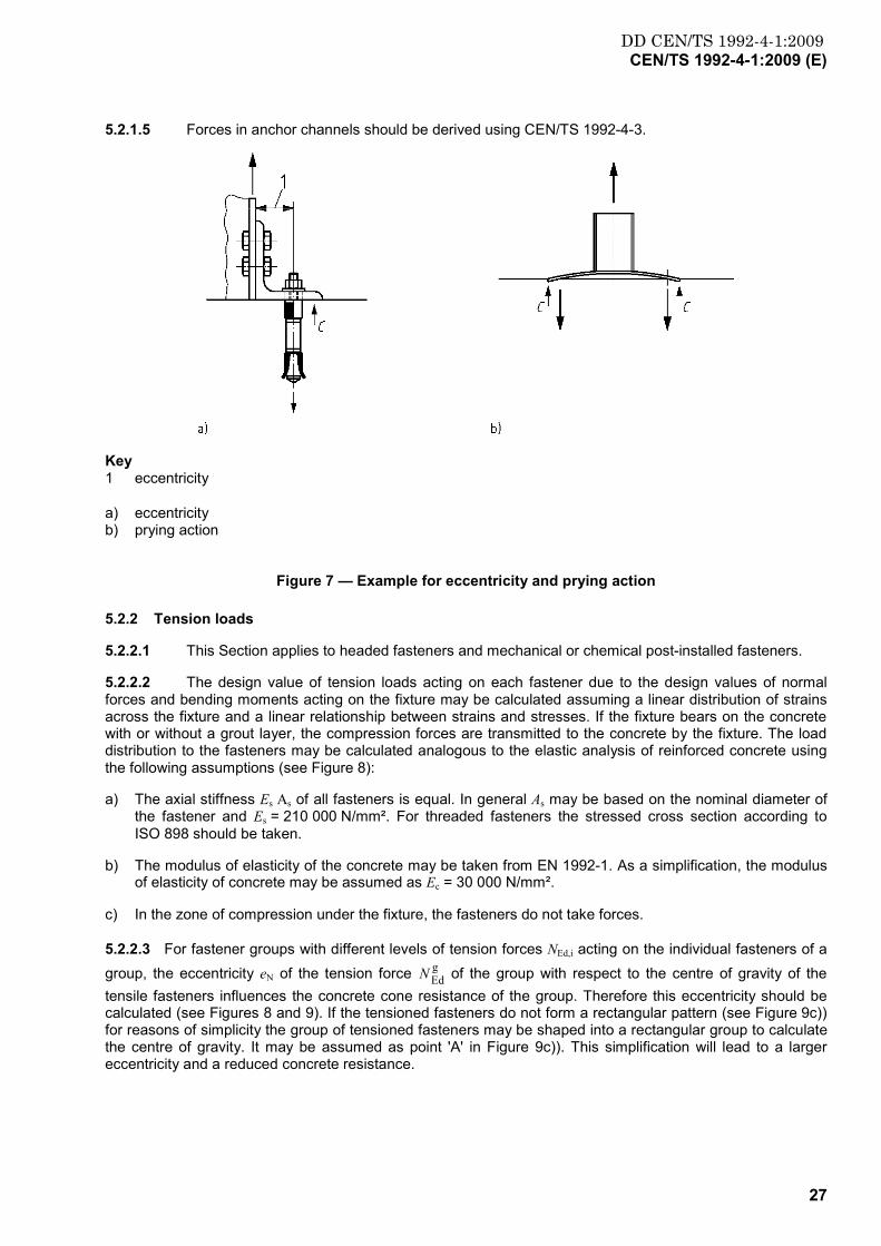
5.2.1.3 Eccentricities and prying effects should be explicitly considered in the design of the fastening (see Figure 7). Prying forces C arise with deformation of the fixture and displacement of the fasteners.
NOTE Prying forces are avoided by using rigid fixtures.
5.2.1.4 In general, elastic analysis may be used for establishing the loads on individual fasteners both at ultimate and serviceability limit states.
For ultimate limit states plastic analysis for headed and post-installed fasteners may be used, if the conditions of Annex B are observed.
DD CEN/TS 1992-4-1:2009CEN/TS 1992-4-1:2009 (E)
27
5.2.1.5 Forces in anchor channels should be derived using CEN/TS 1992-4-3.
Key 1 eccentricity
a) eccentricity b) prying action
Figure 7 — Example for eccentricity and prying action
5.2.2 Tension loads
5.2.2.1 This Section applies to headed fasteners and mechanical or chemical post-installed fasteners.
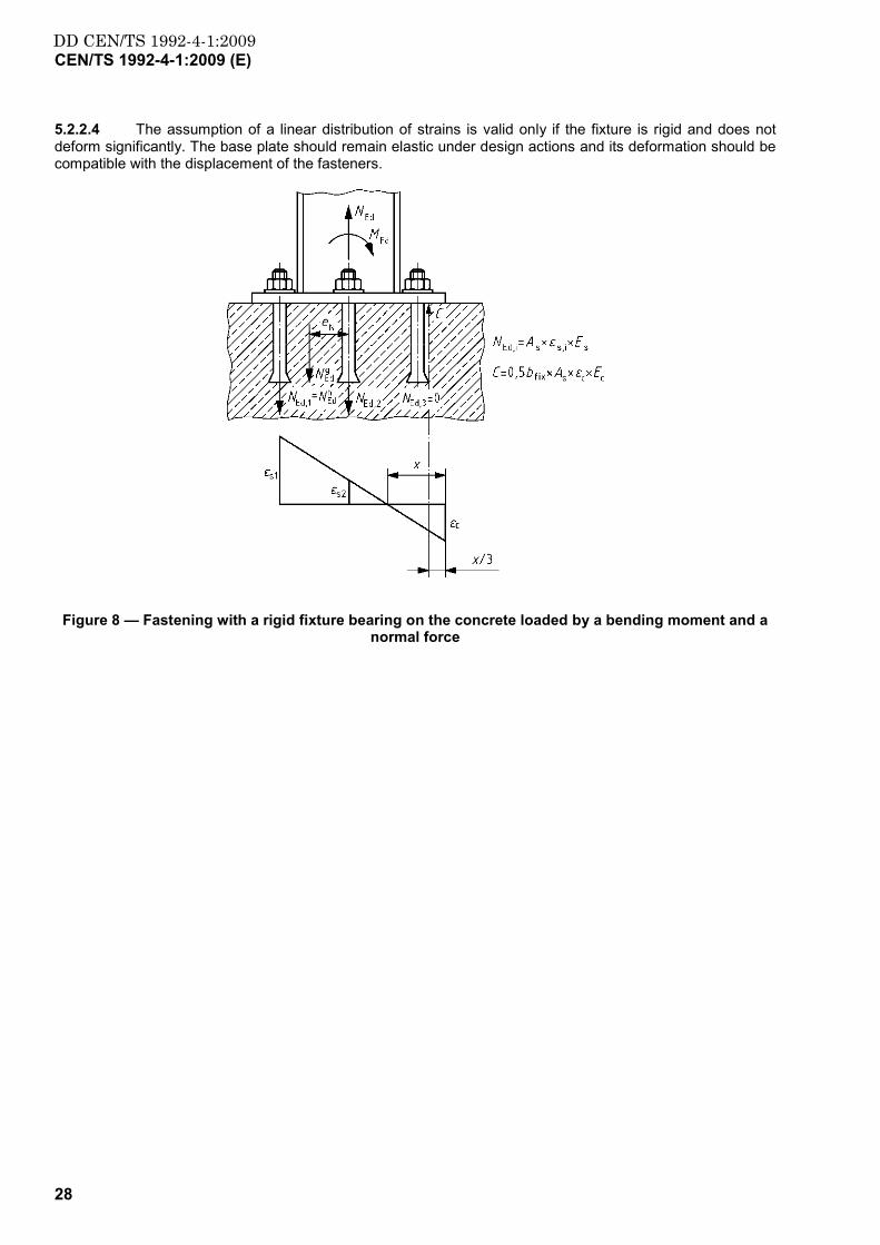
5.2.2.2 The design value of tension loads acting on each fastener due to the design values of normal forces and bending moments acting on the fixture may be calculated assuming a linear distribution of strains across the fixture and a linear relationship between strains and stresses. If the fixture bears on the concrete with or without a grout layer, the compression forces are transmitted to the concrete by the fixture. The load distribution to the fasteners may be calculated analogous to the elastic analysis of reinforced concrete using the following assumptions (see Figure 8):
a) The axial stiffness Es As of all fasteners is equal. In general As may be based on the nominal diameter of the fastener and Es = 210 000 N/mm². For threaded fasteners the stressed cross section according to ISO 898 should be taken.
b) The modulus of elasticity of the concrete may be taken from EN 1992-1. As a simplification, the modulus of elasticity of concrete may be assumed as Ec = 30 000 N/mm².
c) In the zone of compression under the fixture, the fasteners do not take forces.
5.2.2.3 For fastener groups with different levels of tension forces NEd,i acting on the individual fasteners of a group, the eccentricity eN of the tension force g
EdN of the group with respect to the centre of gravity of the tensile fasteners influences the concrete cone resistance of the group. Therefore this eccentricity should be calculated (see Figures 8 and 9). If the tensioned fasteners do not form a rectangular pattern (see Figure 9c)) for reasons of simplicity the group of tensioned fasteners may be shaped into a rectangular group to calculate the centre of gravity. It may be assumed as point 'A' in Figure 9c)). This simplification will lead to a larger eccentricity and a reduced concrete resistance.
DD CEN/TS 1992-4-1:2009CEN/TS 1992-4-1:2009 (E)
28
5.2.2.4 The assumption of a linear distribution of strains is valid only if the fixture is rigid and does not deform significantly. The base plate should remain elastic under design actions and its deformation should be compatible with the displacement of the fasteners.
Figure 8 — Fastening with a rigid fixture bearing on the concrete loaded by a bending moment and a normal force

DD CEN/TS 1992-4-1:2009CEN/TS 1992-4-1:2009 (E)
29
Key 1 compressed area 2 neutral axis 3 centre of gravity of tensile fasteners 4 point of resulting tensile force of tensile fasteners 5 point 'A'
a) eccentricity in one direction, all fasteners are loaded by a tension force b) eccentricity in one direction, only a part of the fasteners of the group are loaded by a tension force c) eccentricity in two directions, only a part of the fasteners of the group are loaded by a tension force
Figure 9 — Examples of fastenings subjected to an eccentric tensile force NEd

DD CEN/TS 1992-4-1:2009CEN/TS 1992-4-1:2009 (E)
30
5.2.3 Shear loads
This Section applies to headed fasteners and mechanical or chemical post-installed fasteners.
5.2.3.1 Distribution of loads
The load distribution depends on the effectiveness of fasteners to resist shear loads. Based on the assumption that the diameter in the hole of the fixture is not larger than the value df given in Table 1 the following cases are distinguished:
All fasteners are considered to be effective if the fastening is located far from the edge (Figure 10) and if fastener steel or concrete pry-out are the governing failure modes;
Only fasteners closest to the edge are assumed to be effective if the fastening is located close to the edge and concrete edge failure governs (Figure 11);
NOTE 1 For groups without hole clearance this approach might be conservative in the case of concrete break-out failure.
The fastener is not considered to be effective if the diameter df in the fixture is exceeded or the hole is slotted in the direction of the shear force.
NOTE 2 Slotted holes may be used to prevent fasteners close to an edge from taking up shear loads and to prevent a premature concrete edge failure (Figure 12).
Table 1 — Hole clearance
1 external diameter da or dnom
b [mm] 6 8 10 12 14 16 18 20 22 24 27 30
2 diameter df of clearance hole in the fixture [mm] 7 9 12 14 16 18 20 22 24 26 30 33
3 a if bolt bears against the fixture (Figure 15a)) b if sleeve bears against the fixture (Figure 15b))
Figure 10 — Examples of load distribution, when all anchors take up shear loads

DD CEN/TS 1992-4-1:2009CEN/TS 1992-4-1:2009 (E)
31
Figure 11 — Examples of load distribution, when only the anchors closest to the edge govern
Figure 12 — Example of a fastening with slotted holes
5.2.3.2 Determination of loads
The design value of the shear forces of the individual fasteners of a group resulting from shear forces and torsion moments acting on the fixture may be calculated using the theory of elasticity assuming equal stiffness for all fasteners of a group and statics. Equilibrium has to be satisfied. Examples are given in Figures 13 and 14.
Independent of the edge distance the calculation of the design value of the shear forces on each fastener due to shear loads and torsional moments acting on the fixture should be carried out to verify steel and pry-out failures.
NOTE Shear loads acting away from the edge do not significantly influence the concrete edge resistance. Therefore for the proof of concrete edge failure these components may be neglected in the calculation of the shear forces on the fasteners close to the edge.

DD CEN/TS 1992-4-1:2009CEN/TS 1992-4-1:2009 (E)
32
Key a [ ] 5,02
22
1p
sdanchor )2/()2/( ss
ITV +⋅= with: pI = radial moment of inertia (here: pI = s1
2 + s22)
a) group with three fasteners in a row b) quadruple fastening c) quadruple fastening under inclined load d) quadruple fastening under torsion moment
Figure 13 —Determination of shear loads when all fasteners are effective (steel and pry-out failure), examples

DD CEN/TS 1992-4-1:2009CEN/TS 1992-4-1:2009 (E)
33
Key a) group with two fasteners loaded perpendicular to the edge; b) group with two fasteners loaded parallel to the edge; c) quadruple fastening loaded by an inclined shear load
Figure 14 — Determination of shear loads when only the fasteners closest to the edge are effective (concrete edge failure), examples
NOTE In case of fastener groups where only the fasteners closest to the edge are effective the component of the load acting perpendicular to the edge is taken up by the fasteners closest to the edge, while the components of the load acting parallel to the edge– due to reasons of equilibrium – are equally distributed to all fasteners of the group (Figure 14c)).
DD CEN/TS 1992-4-1:2009CEN/TS 1992-4-1:2009 (E)
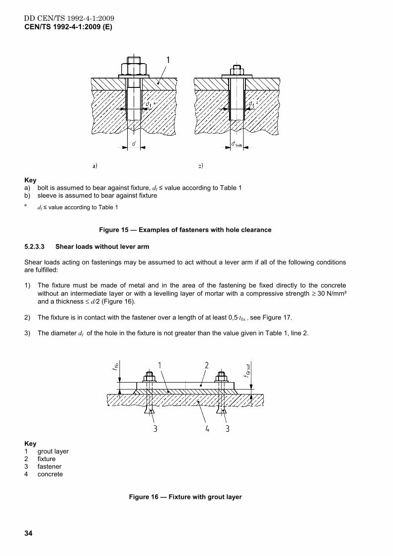
34
Key a) bolt is assumed to bear against fixture, df ≤ value according to Table 1 b) sleeve is assumed to bear against fixture a df ≤ value according to Table 1
Figure 15 — Examples of fasteners with hole clearance
5.2.3.3 Shear loads without lever arm
Shear loads acting on fastenings may be assumed to act without a lever arm if all of the following conditions are fulfilled:
1) The fixture must be made of metal and in the area of the fastening be fixed directly to the concrete without an intermediate layer or with a levelling layer of mortar with a compressive strength ≥ 30 N/mm² and a thickness ≤ d/2 (Figure 16).
2) The fixture is in contact with the fastener over a length of at least 0,5⋅tfix , see Figure 17.
3) The diameter df of the hole in the fixture is not greater than the value given in Table 1, line 2.
Key 1 grout layer 2 fixture 3 fastener 4 concrete
Figure 16 — Fixture with grout layer
DD CEN/TS 1992-4-1:2009CEN/TS 1992-4-1:2009 (E)
35
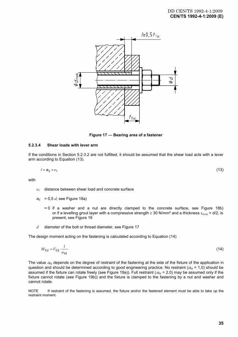
Figure 17 — Bearing area of a fastener
5.2.3.4 Shear loads with lever arm
If the conditions in Section 5.2.3.2 are not fulfilled, it should be assumed that the shear load acts with a lever arm according to Equation (13).
13 el += a (13)
with
e1 distance between shear load and concrete surface
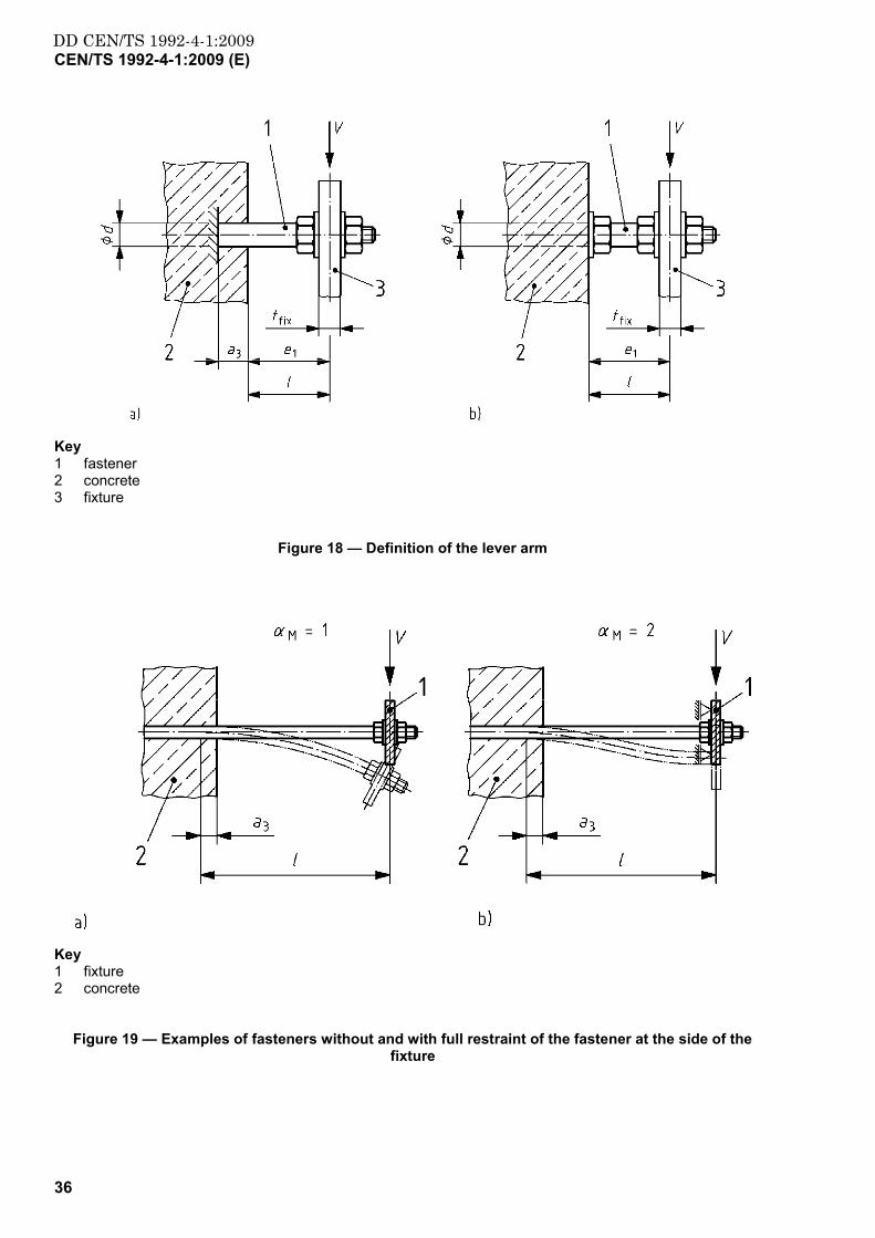
a3 = 0,5 d, see Figure 18a)
= 0 if a washer and a nut are directly clamped to the concrete surface, see Figure 18b) or if a levelling grout layer with a compressive strength ≥ 30 N/mm² and a thickness tGrout > d/2, is present, see Figure 16
d diameter of the bolt or thread diameter, see Figure 17
The design moment acting on the fastening is calculated according to Equation (14)
MEdEd α
lVM ⋅= (14)
The value αM depends on the degree of restraint of the fastening at the side of the fixture of the application in question and should be determined according to good engineering practice. No restraint (αM = 1,0) should be assumed if the fixture can rotate freely (see Figure 19a)). Full restraint (αM = 2,0) may be assumed only if the fixture cannot rotate (see Figure 19b)) and the fixture is clamped to the fastening by a nut and washer and cannot rotate.
NOTE If restraint of the fastening is assumed, the fixture and/or the fastened element must be able to take up the restraint moment.
DD CEN/TS 1992-4-1:2009CEN/TS 1992-4-1:2009 (E)
36
Key 1 fastener 2 concrete 3 fixture
Figure 18 — Definition of the lever arm
Key 1 fixture 2 concrete
Figure 19 — Examples of fasteners without and with full restraint of the fastener at the side of the fixture

DD CEN/TS 1992-4-1:2009CEN/TS 1992-4-1:2009 (E)
37
6 Verification of ultimate limit state
6.1 General
6.1.1 It shall be demonstrated that Equation (1) is fulfilled for all loading directions (tension, shear, combined tension and shear) as well as all failure modes (see Figures 20 and 21). When using plastic analysis additional checks are required (see Annex B).
6.1.2 Verifications and the series CEN/TS 1992-4 required for the different fastener types are given in the product-specific Parts 2 to 5 of this CEN/TS.
6.1.3 Special reinforcement may be provided to take up tension loads, shear loads or combined tension and shear loads. The corresponding design methods are given in the product-specific Parts of this CEN/TS.
6.1.4 Both minimum edge distance and spacing should only be specified with positive tolerances. If this requirement cannot be met, then the influence of negative tolerances on the design resistance shall be taken into account in the design.
Key a1) pull-out failure a2) pull-out failure (bond failure) b1), b2), b3) concrete cone failures b4) concrete blow-out failure c) splitting failure d) steel failure
Figure 20 — Failure modes under tensile loading
DD CEN/TS 1992-4-1:2009CEN/TS 1992-4-1:2009 (E)
38
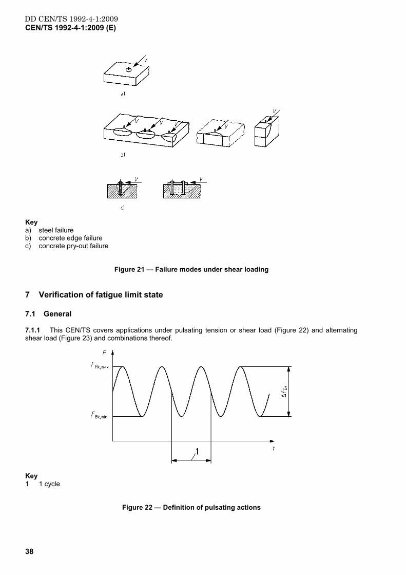
Key a) steel failure b) concrete edge failure c) concrete pry-out failure
Figure 21 — Failure modes under shear loading
7 Verification of fatigue limit state
7.1 General
7.1.1 This CEN/TS covers applications under pulsating tension or shear load (Figure 22) and alternating shear load (Figure 23) and combinations thereof.
Key 1 1 cycle
Figure 22 — Definition of pulsating actions

DD CEN/TS 1992-4-1:2009CEN/TS 1992-4-1:2009 (E)
39
Key 1 1 cycle
Figure 23 — Definition of alternating shear actions
7.1.2 Fatigue verification should be carried out when fasteners are subjected to regular load cycles (e.g. fastening of cranes, reciprocating machinery, guide rails of elevators).
Fatigue load cycling may also arise at restraints of members subjected to temperature variations, e.g. facades.
NOTE In general, fatigue verification is not required in the following cases:
Less than 1 000 load cycles for pulsating tension, shear or combined tension and shear loads with a load range minmax ,, FFF EkEkEk −=∆ equal to the allowable load for static loading, which is QRd γ/F with
FRd = design resistance for steel failure and γ Q = 1,5.
Less than 15 load cycles of alternating shear loads with a load range twice the allowable value for static loading. For smaller load ranges the number of load cycles, where no verification is required, may be increased.
With load cycles imposed by temperature variations (e.g. fastening of façade elements), if the stress range caused by the restraint forces in the most stressed fastener minmax σσσ −=∆ is limited to 100 N/mm² (bending stresses in the fastener e.g. in a stand-off installation) or in the case of shear loads, if the maximum stress range in the cross section of the most stressed fastener is limited to
2N/mm60minmax ≤−=∆ τττ (τ = shear stress in the fastener).
7.1.3 Fasteners used to resist fatigue loading should be prequalified by a European Technical Specification for this application.
7.1.4 Annular gaps are not allowed and loosening of the nut or screw shall be avoided. Therefore a permanent prestressing force on the fastener shall be present during the service life of the fastener.
NOTE This requirement can be fulfilled e.g. by using special installation sets.
7.1.5 The verification of the resistance under fatigue loading consists of both, the verification under static and fatigue loading. Under static loading the fasteners should be designed based on the design methods given in clause 6. The verifications under fatigue loading are given in 7.3.
7.2 Derivation of loads acting on fasteners
Clause 5.2 applies.

DD CEN/TS 1992-4-1:2009CEN/TS 1992-4-1:2009 (E)
40
7.3 Resistance
7.3.1 The required verifications for all load directions are summarised in Tables 2 and 3. In general, the values for resistances are considered valid for up to 2⋅106 cycles. The maximum number of cycles is stated in the relevant European Technical Specification.
NOTE To account for the unequal resistance of fasteners within a group arising from possible differences in stiffness of and load distribution to fasteners, the fatigue resistance of the most loaded fastener is multiplied with a reduction factor ψFN for tensile loading or ψFV for shear loading. The factors ψFV and ψFN are given in a European Technical Specification. For groups with 2 fasteners under shear load perpendicular to the axis of the fasteners when the fixture is able to rotate ψFV = 1.
Table 2 — Required verifications — tension loading
Single fastener
Fastener group
most loaded fastener fastener group
Steel failure fatNMs
sRkEkfatF
,,
,, γ
NNγ
∆≤∆⋅
fatNMs
sRkFNhEkfatF
,,
,, γ
NΨNγ
∆⋅≤∆⋅
Pull-out failure fatMp
pRkEkfatF
,
,, γ
NNγ
∆≤∆⋅
fatMp
pRkFNhEkfatF
,
,, γ
NΨNγ
∆⋅≤∆⋅
Concrete cone failure fatMc
cRkEkfatF
,
,, γ
NNγ
∆≤∆⋅
fatMc
cRkgEkfatF
,
,, γ
NNγ
∆≤∆⋅
Concrete splitting failure fatMc
spRkEkfatF
,
,, γ
NNγ
∆≤∆⋅
fatMc
spRkgEkfatF
,
,, γ
NNγ
∆≤∆⋅
Concrete blow-out failure fatMc
cbRkEkfatF
,
,, γ
NNγ
∆≤∆⋅
fatMc
cbRkgEkfatF
,
,, γ
NNγ
∆≤∆⋅
with
γF,fat , γMc,fat, γMp,fat, according to 4.4
γ Ms,N,fat = γ Ms according to 4.4.3.2
ψFN ≤ 1 for fastener groups, taken from a European Technical Specification
∆ΝEk = ∆ΝEk,max - ∆ΝEk,min, twice the amplitude of the fatigue tensile action, see Figure 22
∆ΝRk, = fatigue resistance, tension, steel, see European Technical Specification
∆ΝRk,c = fatigue resistance, tension, concrete, = 0,6 ⋅ NRk,c (NRk,c see product relevant Part of the series CEN/TS 1992-4)
∆ΝRk,p = fatigue resistance, tension, pull-out, see European Technical Specification
∆ΝRk,sp = fatigue resistance, tension, concrete splitting, = 0,6 ⋅ ΝRk,sp (ΝRk,sp see product relevant Part of the series CEN/TS 1992-4)
∆ΝRk,cb = fatigue resistance, tension, concrete blow-out, = 0,6 ⋅ ΝRk,cb (ΝRk,cb see product relevant Part of the series CEN/TS 1992-4)

DD CEN/TS 1992-4-1:2009CEN/TS 1992-4-1:2009 (E)
41
Table 3 — Required verifications — shear loading
Single fastener Fastener Group
most loaded fastener fastener group
Steel failure without lever arm fatVMs
sRkEkfatF
,,
,, γ
VVγ
∆≤∆⋅
fatVMs
sRkFVhEkfatF
,,
,, γ
VΨVγ
∆⋅≤∆⋅
Steel failure with lever arm fatVMs
sRkEkfatF
,,
,, γ
VVγ
∆≤∆⋅
fatVMs
sRkFVhEkfatF
,,
,, γ
VΨVγ
∆⋅≤∆⋅
Concrete pry-out failure fatMc
cpRkEkfatF
,
,, γ
VVγ
∆≤∆⋅
fatMc
cpRkgEkfatF
,
,, γ
VVγ
∆≤∆⋅
Concrete edge failure fatMc
cRkEkfatF
,
,, γ
VVγ
∆≤∆⋅
fatMc
cpRkgEkfatF
,
,, γ
VVγ
∆≤∆⋅
with
γF,fat , γMc,fat according to 4.4
ψFV ≤ 1 for fastener groups, taken from a European Technical Specification
γ Ms,V, fat = γ Ms,V according to 4.4.3.2
∆VEk = VEk,max - VEk,min, twice the amplitude of the fatigue shear action, see Figure 23
∆VRk,s = fatigue resistance, shear, steel, see European Technical Specification
∆VRk,c = fatigue resistance, shear, concrete edge failure, = 0,6 VRk,c, (VRk,c see product relevant Part of the series CEN/TS 1992-4)
∆VRk,cp = fatigue resistance, shear, concrete pry-out failure, = 0,6 VRk,cp, (VRk,cp see product relevant Part of the series CEN/TS 1992-4)
For combined tension and shear loading the following equations shall be satisfied:
1≤⋅
⋅=
MRkFN
EkfatFfatN ∆
∆/γNΨ
Nγβ ,
, (15)
1≤⋅
⋅=
MRkFV
EkfatFfatV ∆
∆/γVΨ
Vγβ ,
, (16)
1)β()β( ,, ≤+ ααfatVfatN (17)
with
ψFN, ψFV = required in the case of steel failure in tension and shear or pull-out failure in tension, taken from a European Technical Specification
α = taken from a European Technical Specification
∆NRk, ∆VRk = minimum values of resistance of the governing failure mode
In Equations (15) to (17) the largest value of βN,fat and βV,fat for the different failure modes shall be taken.

DD CEN/TS 1992-4-1:2009CEN/TS 1992-4-1:2009 (E)
42
8 Verification for seismic loading
8.1 General
8.1.1 This clause provides additional requirements for fastenings used to transmit seismic actions by means of tension, shear, or a combination of tension and shear
a) between connected structural elements; or
b) between non-structural attachments and structural elements.
8.1.2 Fixtures with a grout layer (Figure 16) are not covered.
8.1.3 Applications for which actions are predominantly high-cycle fatigue or impact are not covered by the provisions in this section.
8.2 Requirements
8.2.1 Fasteners used to resist seismic actions shall meet all applicable requirements for non-seismic applications.
8.2.2 Only fasteners qualified for seismic applications shall be used (see relevant European Technical Specification).
8.2.3 The concrete in the region of the fastening shall be assumed to be cracked when determining design resistance.
8.2.4 The provisions in this section do not apply to the design of fastenings in critical regions of concrete elements where concrete spalling or excessive cracking may occur e.g. plastic hinge zones (critical regions) of concrete structures. The critical region length lcr is defined in EN 1998-1.
NOTE Crack widths in critical regions can be much larger than those for which the fasteners are qualified
8.2.5 Displacement of the fastening should be accounted for by engineering judgment e.g. when anchoring structural elements or non-structural elements of great importance or of a particularly dangerous nature.
NOTE Fastener displacements are provided in the relevant European Technical Specification.
8.2.6 Determination of distribution of forces to the individual fasteners of a group shall take into account the stiffness of the fixture and its ability to redistribute loads to other anchors in the group beyond yield of the fixture.
8.2.7 In general, annular gaps between a fastener and its fixture should be avoided for seismic design situations. Where in minor non-critical applications this requirement is not fulfilled, the effect of the annular gap (df ≤ df,1) on the distribution of shear loads in the case of groups and on the resistance should be taken into account. Loosening of the nut or screw shall be prevented by appropriate measures.
8.3 Actions
The design value of the effect of seismic actions Ed acting on the fixture shall be determined according to EN 1998-1.
NOTE Extension of the requirements in EN 1998-1 to include vertical seismic actions acting on non-structural elements and tables to aid the designer are provided in Annex E.
8.4 Resistance
8.4.1 The partial factors for resistance γM shall be determined according to 4.4.3.

DD CEN/TS 1992-4-1:2009CEN/TS 1992-4-1:2009 (E)
43
8.4.2 The seismic design resistance Rd,eq of a fastening shall be taken as the design resistance as determined for the persistent and transient elastic design situation (see clause 6) using the values for the characteristic seismic resistance Rk,eq provided by a European Technical Specification:
M
eqk,eqeqd, γ
αR
R ⋅= (18)
with
eqα = 0,75 for concrete related failures: concrete cone, pull-out, blow-out and splitting failure under tension loading; pry-out and concrete edge failure under shear loading
= 1,0 for steel failure
eqk,R characteristic seismic resistance for a given failure mode, see relevant European Technical Specification
8.4.3 When the fastening design includes seismic actions one of the following conditions shall be satisfied:
(1) The anchorage is designed for the minimum of the following:
The force corresponding to yield of a ductile steel component taking into account over-strength (see Figure 24a), b)).
The maximum force that can be transferred to the connection by the attached component or structural system (see Figure 24c)).
Key a) yielding in attached element; b) yielding in baseplate; c) capacity of attached element
Figure 24 — Seismic design by protection of the fastening
(2) The fastener is designed for ductile steel failure (see Figure 25). To ensure ductile steel failure Equation (19) shall be satisfied:
inst
eqconc,k,eqs,k, 6,0
γR
R ⋅≤ (19)
with
eqs,k,R characteristic seismic resistance for steel failure
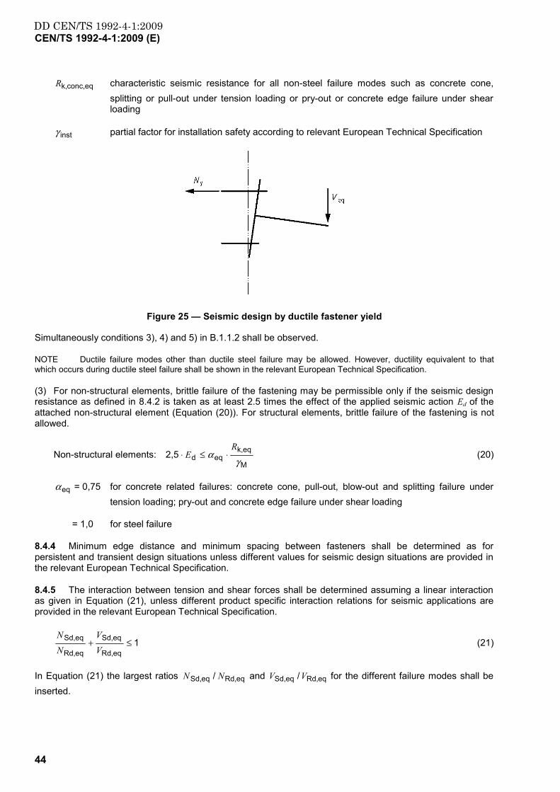
DD CEN/TS 1992-4-1:2009CEN/TS 1992-4-1:2009 (E)
44
eqconc,k,R characteristic seismic resistance for all non-steel failure modes such as concrete cone, splitting or pull-out under tension loading or pry-out or concrete edge failure under shear loading
instγ partial factor for installation safety according to relevant European Technical Specification
Figure 25 — Seismic design by ductile fastener yield
Simultaneously conditions 3), 4) and 5) in B.1.1.2 shall be observed.
NOTE Ductile failure modes other than ductile steel failure may be allowed. However, ductility equivalent to that which occurs during ductile steel failure shall be shown in the relevant European Technical Specification.
(3) For non-structural elements, brittle failure of the fastening may be permissible only if the seismic design resistance as defined in 8.4.2 is taken as at least 2.5 times the effect of the applied seismic action Ed of the attached non-structural element (Equation (20)). For structural elements, brittle failure of the fastening is not allowed.
Non-structural elements: M
eqk,eqd2,5
γα
RE ⋅≤⋅ (20)
eqα = 0,75 for concrete related failures: concrete cone, pull-out, blow-out and splitting failure under tension loading; pry-out and concrete edge failure under shear loading
= 1,0 for steel failure
8.4.4 Minimum edge distance and minimum spacing between fasteners shall be determined as for persistent and transient design situations unless different values for seismic design situations are provided in the relevant European Technical Specification.
8.4.5 The interaction between tension and shear forces shall be determined assuming a linear interaction as given in Equation (21), unless different product specific interaction relations for seismic applications are provided in the relevant European Technical Specification.
1eqRd,
eqSd,
eqRd,
eqSd, ≤+VV
NN
(21)
In Equation (21) the largest ratios eqRd,eqSd, / NN and eqRd,eqSd, /VV for the different failure modes shall be inserted.

DD CEN/TS 1992-4-1:2009CEN/TS 1992-4-1:2009 (E)
45
9 Verification of serviceability limit state
9.1 For the required verification see 4.2 and 4.3.
9.2 The admissible displacement Cd should be evaluated by the designer taking into account the type of application in question (e.g. the structural element to be fastened).
It may be assumed that the displacements Cd are a linear function of the applied load. In the case of combined tension and shear load, the displacements for the shear and tension components of the resultant load should be added vectorially.
The characteristic displacement of the fastener under given tension and shear loads shall be taken from the relevant European Technical Specification.
DD CEN/TS 1992-4-1:2009CEN/TS 1992-4-1:2009 (E)
46
Annex A (normative)
Local transmission of fastener loads into the concrete member
A.1 General
The design methods given in this TS will ensure the transmission of the loads on the fixture to the concrete member.
The transmission of the fastener loads to the supports of the concrete member shall be shown for the ultimate limit state and the serviceability limit state according to EN 1992-1-1 taking into account the additional provisions given in A.1.2 and A.1.3.
In the case of slabs and beams made out of thin prefabricated concrete units and added cast-in-place concrete, fastener loads may be transmitted into the prefabricated concrete only if the precast concrete is connected with the cast-in-place concrete by a shear reinforcement. If this shear reinforcement between precast and cast-in-place concrete is not present, the fasteners should be embedded with hef in the added concrete. Otherwise only the loads of suspended ceilings or similar constructions with a load up to 1,0 kN/m2 may be fastened in the precast concrete.
A.2 Verification of the shear resistance of the concrete member
A.2.1 No special additional verification for local transmission of loads is required, if one of the following conditions is met
a) The shear force VEd at the support caused by the design actions including the fastener loads is
VEd ≤ 0,8 VRd,c member without shear reinforcement (A.1)
≤ 0,8·min(VRd,s, VRd,max) member with shear reinforcement (A.2)
with
VRd,c, VRd,s VRd,max = shear resistance according EN 1992-1-1
b) Under the characteristic actions, the resultant tension force NEk of the tensioned fasteners is NEk < 30 kN and the spacing a between the outermost fasteners of adjacent groups or between the outer fasteners of a group and individual fasteners satisfies Equation (A.3)
a > 200 EkN [mm] (A.3)
with
NEK [kN]
c) The fastener loads are taken up by a hanger reinforcement, which encloses the tension reinforcement and is anchored at the opposite side of the concrete member. Its distance from an individual fastener or the outermost fasteners of a group should be smaller than hef.
d) If the embedment depth of the fastener is hef ≥ 0,8·h.
A.2.2 If the conditions of A.2.1 are not fulfilled, the shear forces VEd,a caused by fastener loads should not exceed the value
DD CEN/TS 1992-4-1:2009CEN/TS 1992-4-1:2009 (E)
47
VEd,a ≤ 0,4 VRd,c member without shear reinforcement (A.4)
= 0,4·min (VRd,s , VRd,max) member with shear reinforcement (A.5)
When calculating VEd,a the fastener loads shall be assumed as point loads with a width of load application t1 = st1 + 2 hef and t2 = st2 + 2 hef, with st1 (st2) equal to the spacing between the outer fasteners of a group in direction 1 (2) (see Figure 6). The active width over which the shear force is transmitted should be calculated according to the theory of elasticity.
A.2.3 If under the characteristic actions the resultant tension force NEk of the tensioned fasteners is NEk > 60 kN, then the conditions in A.1.2.1c) or A.1.2.1d) should be complied with.
A.3 Verification of the resistance to splitting forces
In general, the splitting forces caused by fasteners should be taken into account in the design of the concrete member. This may be neglected if one of the following conditions is met:
a) The load transfer area is in the compression zone of the concrete member.
b) The tension component NEk of the characteristic loads acting on the fastening (single fastener or group of fasteners) is smaller than 10 kN.
c) The tension component NEk is not greater than 30 kN. In addition, for fastenings in slabs and walls a concentrated reinforcement in longitudinal and transverse direction is present in the region of the fastening. The area of the transverse reinforcement should be at least 60 % of the longitudinal reinforcement required for the actions due to fastener loads.
If the characteristic tension load acting on the fastening is NEk > 30 kN and the fasteners are located in the tension zone of the concrete member, the splitting forces shall be taken up by reinforcement. As a first indication for fasteners according to current experience the splitting force FSp,k may be taken as
FSp,k = 2,0 NEk deformation-controlled expansion fasteners
= 1,5 NEk torque-controlled expansion fasteners
= 1,0 NEk undercut fasteners
= 0,5 NEk bonded fasteners, headed fasteners, anchor channels
NOTE If undercut fasteners fulfil the requirements of the series CEN/TS 1992-4-2:, Clause 6 for headed fasteners on the pressure under the head, FSp,k may be taken as FSp,k = 0,5 NEk.
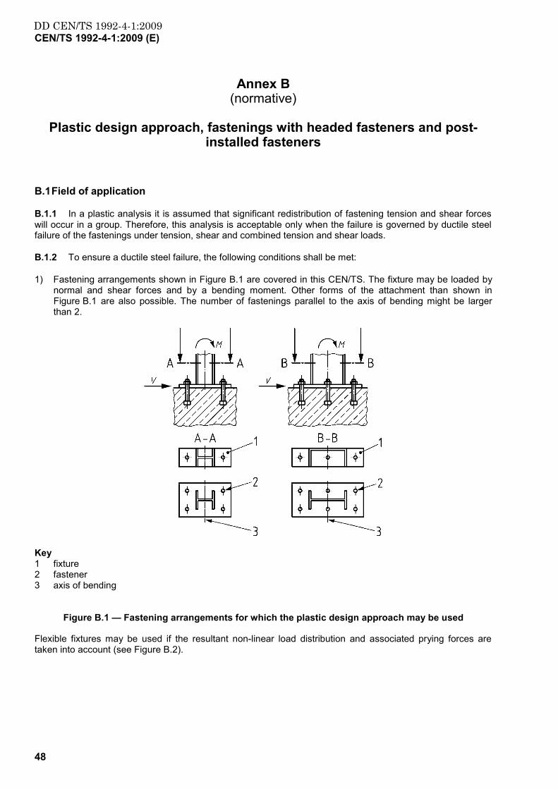
DD CEN/TS 1992-4-1:2009CEN/TS 1992-4-1:2009 (E)
48
Annex B (normative)
Plastic design approach, fastenings with headed fasteners and post-
installed fasteners
B.1 Field of application
B.1.1 In a plastic analysis it is assumed that significant redistribution of fastening tension and shear forces will occur in a group. Therefore, this analysis is acceptable only when the failure is governed by ductile steel failure of the fastenings under tension, shear and combined tension and shear loads.
B.1.2 To ensure a ductile steel failure, the following conditions shall be met:
1) Fastening arrangements shown in Figure B.1 are covered in this CEN/TS. The fixture may be loaded by normal and shear forces and by a bending moment. Other forms of the attachment than shown in Figure B.1 are also possible. The number of fastenings parallel to the axis of bending might be larger than 2.
Key 1 fixture 2 fastener 3 axis of bending
Figure B.1 — Fastening arrangements for which the plastic design approach may be used
Flexible fixtures may be used if the resultant non-linear load distribution and associated prying forces are taken into account (see Figure B.2).

DD CEN/TS 1992-4-1:2009CEN/TS 1992-4-1:2009 (E)
49
Key a prying force
Figure B.2 — Example of a fastening with a flexible fixture loaded by a bending moment and a tension force
2) The design resistance of a fastener as governed by concrete failure should exceed the design resistance as governed by steel failure. Resistance models given in Clause B.3 will satisfy this requirement.
3) The nominal steel strength of the fasteners should not exceed MPa800=ukf , the ratio nominal steel yield strength to nominal ultimate strength shall not exceed 0,8=ukyk f/f , and the rupture elongation (measured over a length equal to 5d) should be at least 12 %.
4) Fasteners that incorporate a reduced section e.g. thread should satisfy the following conditions:
a) For fasteners loaded in tension, the strength Nuk of the reduced section should either be greater than 1,1-times the yield strength Nyk of the unreduced section or the stressed length of the reduced section should be ≥ 5 d (d = fastening diameter outside reduced section).
b) For fasteners loaded in shear or which shall redistribute shear forces, the start of the reduced section should either be ≥ 5 d below the concrete surface or in the case of a threaded fastener, the threaded part should extend ≥ 2 d into the concrete.
c) For fasteners loaded in combined tension and shear, the conditions (a) and (b) above should be met.
5) The steel fixture should be embedded in the concrete or fastened to the concrete surface without an intermediate layer or with a levelling layer of mortar with a compressive strength ≥ 30 N/mm² and a thickness ≤ d/2.
6) The diameter of the clearance holes in the fixture should be smaller than the values given in the product relevant Parts of this CEN/TS.

DD CEN/TS 1992-4-1:2009CEN/TS 1992-4-1:2009 (E)
50
B.2 Loads on fastenings
It may be assumed that all fasteners are stressed up to their design resistance without taking into account compatibility conditions. The conditions given in B.2.1 to B.2.5 should be met:
B.2.1 For design purposes, the compressive stress between fixture and concrete may be assumed to be a rectangular stress block with cdc fσ ⋅= 3 .
B.2.2 The location of the resultant compressive force shall be determined based on rigid or flexible base plate behaviour in accordance with the following:
a) Rigid base plate behaviour
For a rigid base plate behaviour the compressive force is assumed to occur at the extreme edge of the base plate as shown in Figure B.3. For a rigid base plate behaviour to occur, the base plate must be of sufficient thickness to prevent yielding of the fixture at the edge of the attached member on the compression side of the fixture. The minimum base plate thickness may be determined by satisfying Equation (B.1)
4Edyd CM a⋅> (B.1)
with
Myd design moment that causes yielding of the fixture calculated with Msykyd γ/ff =
CEd design resultant compressive force
4a distance from the edge of the attached member to the resultant compressive force
NOTE The value of γMs for use in a country may be found in its National Annex. The recommended value is γMs = 1,1.
Key 1 4Edyd aCM ⋅> , no yielding allowed
Figure B.3 — Rigid base plate behaviour
b) Flexible base plate behaviour
In the case of a flexible base plate, the distance a5 between the edge of the attached member and the resultant of the compressive reaction may be calculated according to Equation (B.2), see Figure B.4.
Edyd C/Ma =5 (B.2)
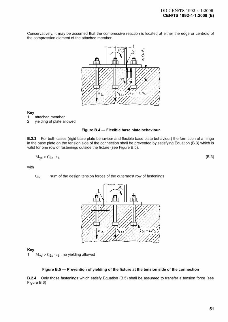
DD CEN/TS 1992-4-1:2009CEN/TS 1992-4-1:2009 (E)
51
Conservatively, it may be assumed that the compressive reaction is located at either the edge or centroid of the compression element of the attached member.
Key 1 attached member 2 yielding of plate allowed
Figure B.4 — Flexible base plate behaviour
B.2.3 For both cases (rigid base plate behaviour and flexible base plate behaviour) the formation of a hinge in the base plate on the tension side of the connection shall be prevented by satisfying Equation (B.3) which is valid for one row of fastenings outside the fixture (see Figure B.5).
6Edyd aCM ⋅> (B.3)
with
CEd sum of the design tension forces of the outermost row of fastenings
Key 1 6Edyd aCM ⋅> , no yielding allowed
Figure B.5 — Prevention of yielding of the fixture at the tension side of the connection
B.2.4 Only those fastenings which satisfy Equation (B.5) shall be assumed to transfer a tension force (see Figure B.6)

DD CEN/TS 1992-4-1:2009CEN/TS 1992-4-1:2009 (E)
52
87 0,4 aa ≥ (B.4)
with
a7 (a8) distance between the resultant compression force and the innermost (outermost) tensioned fastener
Figure B.6 — Condition for fasteners transferring a tension force equal to the yield force
B.2.5 It may be assumed that all fasteners or only some of the fasteners carry shear loads. The shear load taken by the individual fasteners of a group may be different.
NOTE With a plastic design approach, the area of fastener steel may be reduced in comparison with an elastic design approach. However, the required anchorage depth and edge distance may be larger than for the elastic design approach to preclude a concrete failure.
B.3 Design of fastenings
In general, the complete fastening is checked according to Equation (4). Therefore the required verifications are written for the group.
B.3.1 Partial factors
In general partial factors used for actions and resistances in the elastic design are also applicable for design based on plastic analysis, except for steel failure. The partial factor for steel γMs,pl is applied to the yield strength fyk.
NOTE The value of γMs,pl for use in a Country may be found in its National Annex. The recommended value is γMs,pl = 1,2.
B.3.2 Resistance to tension load
B.3.2.1 Required verifications
The required verifications are summarized in Table B.1.
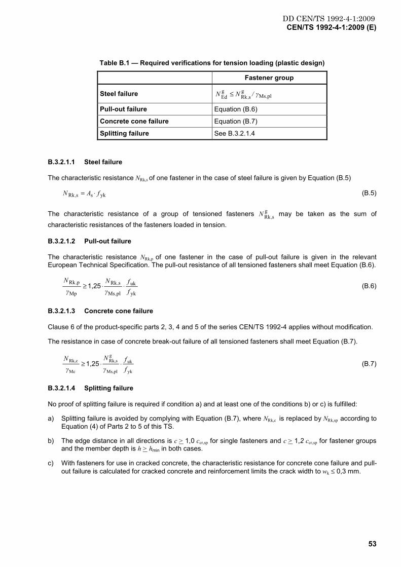
DD CEN/TS 1992-4-1:2009CEN/TS 1992-4-1:2009 (E)
53
Table B.1 — Required verifications for tension loading (plastic design)
Fastener group
Steel failure plMsg
sRkgEd ,, γ/NN ≤
Pull-out failure Equation (B.6)
Concrete cone failure Equation (B.7)
Splitting failure See B.3.2.1.4
B.3.2.1.1 Steel failure
The characteristic resistance NRk,s of one fastener in the case of steel failure is given by Equation (B.5)
ykssRk fAN , ⋅= (B.5)
The characteristic resistance of a group of tensioned fasteners gsRk ,N may be taken as the sum of
characteristic resistances of the fasteners loaded in tension.
B.3.2.1.2 Pull-out failure
The characteristic resistance NRk,p of one fastener in the case of pull-out failure is given in the relevant European Technical Specification. The pull-out resistance of all tensioned fasteners shall meet Equation (B.6).
yk
uk
plMs
sRk
Mp
pRk
ff
γN
γN
,
,, ⋅⋅≥ 1,25 (B.6)
B.3.2.1.3 Concrete cone failure
Clause 6 of the product-specific parts 2, 3, 4 and 5 of the series CEN/TS 1992-4 applies without modification.
The resistance in case of concrete break-out failure of all tensioned fasteners shall meet Equation (B.7).
yk
uk
plMs,
gsRk,
Mc
cRk,
ff
γ
N
γN
⋅⋅≥ 1,25 (B.7)
B.3.2.1.4 Splitting failure
No proof of splitting failure is required if condition a) and at least one of the conditions b) or c) is fulfilled:
a) Splitting failure is avoided by complying with Equation (B.7), where NRk,c is replaced by NRk,sp according to Equation (4) of Parts 2 to 5 of this TS.
b) The edge distance in all directions is c > 1,0 ccr,sp for single fasteners and c > 1,2 ccr,sp for fastener groups and the member depth is h > hmin in both cases.
c) With fasteners for use in cracked concrete, the characteristic resistance for concrete cone failure and pull-out failure is calculated for cracked concrete and reinforcement limits the crack width to wk ≤ 0,3 mm.

DD CEN/TS 1992-4-1:2009CEN/TS 1992-4-1:2009 (E)
54
B.3.3 Resistance to shear load
B.3.3.1 Required verifications
The required verifications are summarised in Table B.2.
Table B.2 —Required verifications for shear loading (plastic design)
Fastener group
Steel failure, shear load without lever arm plMsg
sRkg
Ed ,, γ/VV ≤
Concrete pry-out failure Equation (B.9)
Concrete edge failure Equation (B.10)
B.3.3.1.1 Steel failure
The characteristic resistance VRk,s of one fastener in the case of steel failure is given by Equation (B.8).
ykssRk fAV , ⋅⋅= 0,5 (B.8)
The characteristic resistance of a group of sheared fasteners gsRk ,V may be taken as equal to the sum of
characteristic resistances of the fasteners loaded in shear.
B.3.3.2 Concrete pry-out failure
Section 6 of the product-specific parts 2, 3, 4 and 5 of the series CEN/TS 1992-4 applies without modification. To satisfy Equation (B.1) the resistance in case of concrete pry-out failure of all sheared fasteners shall meet Equation (B.9).
yk
uk
plMs
gsRk
Mc
cpRk
ff
γ
V
γV
,
,, ⋅⋅≥ 1,25 (B.9)
NOTE Equation (B.9) is satisfied if all fasteners are anchored with an anchorage depth so that Equation (B.7) is met.
B.3.3.3 Concrete edge failure
Section 6 of the product specific parts 2, 4, and 5 of the series CEN/TS 1992-4 applies without modification.
The concrete edge resistance of all sheared fasteners shall meet Equation (B.10).
yk
uk
plMs
gsRk
Mc
cRk
ff
γ
V
γV
,
,, ⋅⋅≥ 1,25 (B.10)
B.3.3.4 Resistance to combined tension and shear load
For combined tension and shear loads the following equations shall be satisfied:
βN ≤ 1 (B.11)
βV ≤ 1 (B.12)
DD CEN/TS 1992-4-1:2009CEN/TS 1992-4-1:2009 (E)
55
βN + βV ≤ 1 (B.13)
where: βN = NEd/NRd and βV = VEd/VRd
DD CEN/TS 1992-4-1:2009CEN/TS 1992-4-1:2009 (E)
56
Annex C (informative)
Durability
C.1 General
In the absence of better information in National Regulations, in the European Technical Specification the provisions of this Annex may be used. These provisions are based on an assumed intended working life of the fastener of 50 years.
Electrolytic corrosion must be prevented between dissimilar metals by suitable separation or by the choice of compatible materials.
C.2 Fasteners in dry, internal conditions
These conditions are similar to exposure class XC1 according to EN 1992-1-1.
In general, no special corrosion protection is necessary for steel parts as coatings provided for preventing corrosion during storage prior to use, to ensure proper functioning is considered sufficient. Malleable cast iron parts in general do not require any protection.
C.3 Fasteners in external atmospheric or in permanently damp internal exposure
These conditions are similar to exposure classes XC2, XC3 and XC4 according to EN 1992-1-1.
Normally stainless steel fasteners of appropriate grade should be used. The grade of stainless steel suitable for the various service environments (marine, industrial, etc.) should be in accordance with existing national rules. In general, austenitic steels with at least 17 to 18 % chromium and 12 to 13 % nickel and addition of molybdenum e.g. material 1.4401, 1.4404, 1.4571, 1.4578 and 1.4439 according to EN 10088-2, EN 10088-3 or equivalent may be used.
C.4 Fasteners in high corrosion exposure by chloride and sulphur dioxide
These conditions are similar to exposure classes XD and XS according to EN 1992-1-1.
Examples for these conditions are permanent, alternating immersion in seawater or the splash zone of seawater, chloride atmosphere of indoor swimming pools or atmosphere with extreme chemical pollution (e.g. in desulphurisation plants or road tunnels, where de-icing materials are used), where special considerations to corrosion resistance shall be given.
The metal parts of the fastener (bolt, screw, nut and washer) should be made of a stainless steel suitable for the high corrosion exposure and shall be in accordance with national rules. In general stainless steel with about 20 % chromium, 20 % nickel and 6 % molybdenum e.g. materials 1.4565, 1.4529 and 1.4547 according to EN 10088-2, EN 10088-3 or equivalent should be used under high corrosion exposure.

DD CEN/TS 1992-4-1:2009CEN/TS 1992-4-1:2009 (E)
57
Annex D (informative)
Exposure to fire – design method
D.1 General
In the absence of specifications concerning the characteristic values for fire resistance in corresponding European Technical Specifications the following modified design method may be used.
The design method is valid for cast-in-place headed anchors, expansion anchors, undercut anchors and concrete screws only. For bonded anchors the fire resistance in the cases of bond and concrete failure is product dependant. Anchor channels are not covered. Therefore no values can be given here and the manufacturer should be consulted.
The fire resistance is classified according to EN 13501-2 using the Standard ISO time-temperature curve (STC).
The design method covers fasteners with a fire exposure from one side only. For fire exposure from more than one side, the design method may be used only, if the edge distance of the fastener is c ≥ 300 mm and c ≥ 2hef.
The design under fire exposure is carried out according to the normal design method for ambient temperature given in this CEN/TS with the following modifications:
D.2 Partial factors
Partial factors for actions γF,fi and for materials γM,fi might be defined in a National Annex to this Specification.
NOTE Values for γF,fi and γM,fi may be found in a country's National Annex to this CEN/TS. The recommended values are γF,fi = 1,0 and γM,fi = 1,0.
D.3 Resistance under fire exposure
D.3.1 General
In the absence of test data for a specific fastener the following characteristic resistances in the ultimate limit state under fire exposure may be taken instead of the values given in the product-specific Parts of this CEN/TS, which are valid for ambient temperature. These values are conservative.
D.3.2 Tension load
D.3.2.1 Steel failure
The characteristic resistance of a fastener in the case of steel failure under fire exposure (characteristic tension strength σRk,s,fi) given in the following Tables D.1 and D.2 may be used. These values are also valid for the unprotected steel part of the fastener outside the concrete.

DD CEN/TS 1992-4-1:2009CEN/TS 1992-4-1:2009 (E)
58
Table D.1 — Characteristic tension strength of a carbon steel fastener under fire exposure
anchor bolt/thread diameter
anchorage depth
hef
characteristic tension strength σRk,s,fi of an unprotected fastener made of carbon steel according to EN 10025 in case of fire exposure in the time up to:
σRk,s,fi [N/mm²]
[mm] [mm] 30 min
(R 15 to R30)
60 min
(R45 and R60)
90 min
(R90)
120 min
(≤ R120)
Ø 6 ≥ 30 10 9 7 5
Ø 8 ≥ 30 10 9 7 5
Ø 10 ≥ 40 15 13 10 8
Ø 12 and greater ≥ 50 20 15 13 10
Table D.2 — Characteristic tension strength of a stainless steel fastener under fire exposure
anchor bolt/thread diameter
anchorage depth
hef
characteristic tension strength σRk,s,fi of an unprotected fastener made of stainless steel of at least according to ISO 3506 in case of fire exposure in the
time up to:
σRk,s,fi [N/mm²]
[mm] [mm] 30 min
(R 15 to R30)
60 min
(R45 and R60)
90 min
(R90)
120 min
(≤ R120)
Ø 6 ≥ 30 10 9 7 5
Ø 8 ≥ 30 20 16 12 10
Ø 10 ≥ 40 25 20 16 14
Ø 12 and greater ≥ 50 30 25 20 16
D.3.2.2 Pull-out/pull-through failure
The characteristic resistance of fasteners installed in concrete classes C20/25 to C50/60 may be obtained from Equation (D.1) and (D.2).
NRk,p,fi(90) = 0,25 ⋅⋅⋅⋅ NRk,p for fire exposure up to 90 minutes (D.1)
NRk,p,fi(120) = 0,20 ⋅⋅⋅⋅ NRk,p for fire exposure between 90 and 120 minutes (D.2)
NRk,p = characteristic resistance given in the relevant European Technical Specification in cracked concrete C20/25 under ambient temperature
D.3.2.3 Concrete cone failure
The characteristic resistance of a single fastener 0ficRk ,,N not influenced by adjacent fasteners or edges of the
concrete member installed in concrete classes C20/25 to C50/60 may be obtained using Equations (D.3) and (D.4). The influence of the different effects of geometry, shell spalling, eccentricity, position and further influencing parameters is taken from the relevant product specific part of this CEN/TS. However, the

DD CEN/TS 1992-4-1:2009CEN/TS 1992-4-1:2009 (E)
59
characteristic spacing and edge distance for fasteners under fire exposure near the edge shall be taken as efNcrNcr hcs ,, 42 == .
0i(90) N Rk,c,f = 0
,0
, NN200h
cRkcRkef ≤⋅ for fire exposure up to 90 minutes (D.3)
0 (120)NRk,c,fi = 0,8 0
cRk,0
cRk, NN200h ≤⋅ef for fire exposure between 90 and 120 minutes (D.4)
hef = effective embedment depth in mm
NRk,c = characteristic resistance of a single fastener in cracked concrete C20/25 under ambient temperature according to the relevant product specific part of this CEN/TS
D.3.2.4 Splitting failure
The assessment of splitting failure due to loading under fire exposure is not required because the splitting forces are assumed to be taken up by the reinforcement.
D.3.3 Shear load
D.3.3.1 Steel failure
D.3.3.1.1 Shear load without lever arm
For the characteristic shear resistance τRk,s,fi of a fastener in the case of steel failure under fire exposure (characteristic strength) the values given in Tables D.1 and D.2 apply. They are also valid for the unprotected steel part of the fastener outside the concrete.
NOTE Limited number of tests have indicated, that the ratio of shear strength to tensile strength increases under fire conditions above that for ambient temperature design. This is a discrepancy to the behaviour in the cold state where the ratio is 0,6.
D.3.3.1.2 Shear load with lever arm
The characteristic resistance of a fastener may be calculated according to the relevant product specific part of this CEN/TS. However the characteristic bending resistance of a single fastener under fire exposure is limited to the characteristic tension strength according to D.3.2.1. The characteristic bending resistance 0
fisRk ,,M may be taken from Equation (D.5).
fisRkel0
fisRk ,,,, σWM ⋅⋅= 1,2 (D.5)
with
σRk,s,fi given in Tables D.1 and D.2
NOTE This approach is based on assumptions.
D.3.3.2 Concrete pry-out failure
The characteristic resistance in case of fasteners installed in concrete classes C20/25 to C50/60 may be obtained using Equations (D.6) and (D.7).
VRk,cp,fi(90) = k ⋅ NRk,c,fi(90) for fire exposure up to 90 minutes (D.6)
VRk,cp,fi(120) = k ⋅ NRk,c,fi(120) for fire exposure between 90 and 120 minutes (D.7)
DD CEN/TS 1992-4-1:2009CEN/TS 1992-4-1:2009 (E)
60
k = factor to be taken from the relevant European Technical Specification (ambient temperature)
NRk,c,fi(90), NRk,c,fi(120) = calculated according to D.3.2.3.
D.3.3.3 Concrete edge failure
The characteristic resistance of a single fastener installed in concrete classes C20/25 to C50/60 may be obtained using Equation (D.8) and (D.9). The influence of the different effects of geometry, thickness, load direction, eccentricity and so on is taken from the relevant product specific part of this CEN/TS.
0(90)Rk,c,fiV = 0,25 ⋅⋅⋅⋅ 0
cRk,V for fire exposure up to 90 minutes (D.8)
0(120)Rk,c,fiV = 0,20 ⋅⋅⋅⋅ 0
Rk,cV for fire exposure between 90 and 120 minutes (D.9)
0cRk,V = initial value of the characteristic resistance of a single fastener in cracked concrete
C20/25 under ambient temperature according to the relevant product specific part of this TS
D.3.4 Combined tension and shear load
The interaction conditions according to the relevant product specific part of this CEN/TS may be taken with the characteristic resistances under fire exposure for the different loading directions for combined tension and shear loads.

DD CEN/TS 1992-4-1:2009CEN/TS 1992-4-1:2009 (E)
61
Annex E (informative)
Recommended additions and alterations to EN 1998-1:2004, 4.3.5 (Design of structures for earthquake resistance) for the design of
fastenings under seismic loading
E.1 General
E.1.1 While EN 1998-1 provides requirements for the design of non-structural elements in its Section 4.3.5, it ignores the vertical accelerations in the calculation of actions. This could lead to unsafe designs for fastenings securing non-structural items. Therefore, additional requirements for fastenings are provided in this Annex.
E.1.2 Furthermore, when calculations are performed to determine the forces acting on non-structural elements according to EN 1998-1, it can often be difficult to establish with confidence the necessary dynamic characteristics of such elements. This Annex provides a pragmatic approach to this problem. This necessarily involves significant approximations and assumptions. While the requirements in this Annex are likely to be satisfactory for most cases, the designer is responsible to see that the requirements of EN 1998-1 are fulfilled.
E.1.3 The requirements in this Annex establish the forces required to design the support and the fastening for the non-structural element, however, do not necessarily assure operability of the non-structural element, i.e. equipment, during or after an earthquake.
E.2 Additions to Section 4.3.5.1 of EN 1998-1:2004
E.2.1 In the design of fastenings for non-structural elements subject to seismic actions, any beneficial effects of friction due to gravity loads should be ignored.
E.2.2 Design documents should contain sufficient information relating to fastenings to enable verification of compliance with this TS.
E.3 Additions and alterations to EN 1998-1:2004, 4.3.5.2
E.3.1 Clauses 4.3.5.2 (2) and (3) of EN 1998-1:2004 may be replaced with E.3.2 and E.3.3, respectively.
E.3.2 The horizontal effects of the seismic action may be determined by applying to the non-structural element a horizontal force Fa which is defined as follows:
Fa = (Sa⋅Wa γa)/qa (E.1)
where
Fa is the horizontal seismic force, acting at the centre of mass of the non-structural element in the most unfavourable direction;
Wa is the weight of the element;
Sa is the horizontal seismic coefficient applicable to non-structural elements, see E.3.3;

DD CEN/TS 1992-4-1:2009CEN/TS 1992-4-1:2009 (E)
62
γa is the importance factor of the element, see E.4;
qa is the behaviour factor of the element, see E.5.
E.3.3 The horizontal seismic coefficient Sa may be calculated using the following expression:
SAhzSS aa ⋅≥
−⋅
+⋅⋅= αα 0,51 (E.2)
with
2
1)(11
3
TT
Aa
a−+
= (E.3)
α is the ratio of the design ground acceleration on type A ground, ag, to the acceleration of gravity g;
S is the soil factor;
z is the height of the non-structural element above the level of application of the seismic action;
H is the building height, measured from the foundation or from the top of a rigid basement;
Aa is the response amplification factor; if the values of Ta and/or T1 are not known, the values in Table E.1 may be used;
Ta is the fundamental vibration period of the non-structural element;
T1 is the fundamental vibration period of the building in the relevant direction.
The value of the seismic coefficient Sa may not be taken less than α · S.
E.3.4 The vertical effects of the seismic action may be determined by applying to the non-structural element a vertical force Fva which is defined as follows:
Fva = (Sva ⋅ Wa γa)/qa (E.4)
where
Fva is the vertical seismic force, acting at the centre of mass of the non-structural element;
Sva is the vertical seismic coefficient applicable to non-structural elements, see E.3.5.
All other terms in Equation (E.4) shall be defined as in E.3.2.
NOTE The vertical effects of the seismic action Fva for non-structural elements may be neglected when the ratio of the vertical component of the design ground acceleration avg to the acceleration of gravity g is less than 1.0 and the gravity loads are transferred through direct bearing of the fixture on the structure (see Figure E.1).
E.3.5 The vertical seismic coefficient Sva may be calculated as follows:
avva AαS ⋅= (E.5)
where
αv is the ratio of the vertical design ground acceleration on type A ground, avg, to the acceleration of gravity g;
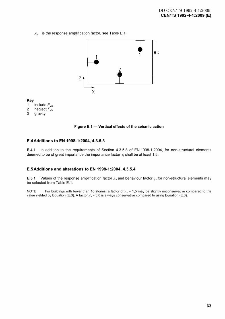
DD CEN/TS 1992-4-1:2009CEN/TS 1992-4-1:2009 (E)
63
Aa is the response amplification factor, see Table E.1.
Key 1 include FVa 2 neglect FVa 3 gravity
Figure E.1 — Vertical effects of the seismic action
E.4 Additions to EN 1998-1:2004, 4.3.5.3
E.4.1 In addition to the requirements of Section 4.3.5.3 of EN 1998-1:2004, for non-structural elements deemed to be of great importance the importance factor γa shall be at least 1,5.
E.5 Additions and alterations to EN 1998-1:2004, 4.3.5.4
E.5.1 Values of the response amplification factor Aa and behaviour factor qa for non-structural elements may be selected from Table E.1.
NOTE For buildings with fewer than 10 stories, a factor of Aa = 1,5 may be slightly unconservative compared to the value yielded by Equation (E.3). A factor Aa = 3,0 is always conservative compared to using Equation (E.3).
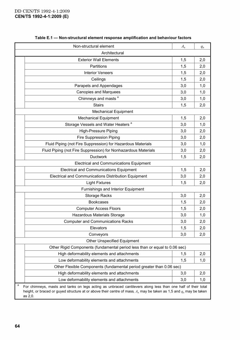
DD CEN/TS 1992-4-1:2009CEN/TS 1992-4-1:2009 (E)
64
Table E.1 — Non-structural element response amplification and behaviour factors
Non-structural element Aa qa
Architectural
Exterior Wall Elements 1,5 2,0 Partitions 1,5 2,0
Interior Veneers 1,5 2,0 Ceilings 1,5 2,0
Parapets and Appendages 3,0 1,0 Canopies and Marquees 3,0 1,0 Chimneys and masts a 3,0 1,0
Stairs 1,5 2,0 Mechanical Equipment
Mechanical Equipment 1,5 2,0 Storage Vessels and Water Heaters a 3,0 1,0
High-Pressure Piping 3,0 2,0 Fire Suppression Piping 3,0 2,0
Fluid Piping (not Fire Suppression) for Hazardous Materials 3,0 1,0 Fluid Piping (not Fire Suppression) for Nonhazardous Materials 3,0 2,0
Ductwork 1,5 2,0 Electrical and Communications Equipment
Electrical and Communications Equipment 1,5 2,0 Electrical and Communications Distribution Equipment 3,0 2,0
Light Fixtures 1,5 2,0 Furnishings and Interior Equipment
Storage Racks 3,0 2,0 Bookcases 1,5 2,0
Computer Access Floors 1,5 2,0 Hazardous Materials Storage 3,0 1,0
Computer and Communications Racks 3,0 2,0 Elevators 1,5 2,0
Conveyors 3,0 2,0 Other Unspecified Equipment
Other Rigid Components (fundamental period less than or equal to 0.06 sec) High deformability elements and attachments 1,5 2,0 Low deformability elements and attachments 1,5 1,0
Other Flexible Components (fundamental period greater than 0.06 sec) High deformability elements and attachments 3,0 2,0 Low deformability elements and attachments 3,0 1,0
a For chimneys, masts and tanks on legs acting as unbraced cantilevers along less than one half of their total height, or braced or guyed structure at or above their centre of mass, Aa may be taken as 1,5 and qa may be taken as 2,0.

DD CEN/TS 1992-4-1:2009
This page has been intentionally left blank
DD CEN/TS1992-4-1:2009
BSI GroupHeadquarters 389Chiswick High Road,London, W4 4AL, UKTel +44 (0)20 8996 9001Fax +44 (0)20 8996 7001www.bsigroup.com/standards
BSI - British Standards InstitutionBSI is the independent national body responsible for preparing BritishStandards. It presents the UK view on standards in Europe and at theinternational level. It is incorporated by Royal Charter.
Revisions
British Standards are updated by amendment or revision. Users of BritishStandards should make sure that they possess the latest amendments oreditions.
It is the constant aim of BSI to improve the quality of our products and services.We would be grateful if anyone finding an inaccuracy or ambiguity while usingthis British Standard would inform the Secretary of the technical committeeresponsible, the identity of which can be found on the inside front cover. Tel:+44 (0)20 8996 9000. Fax: +44 (0)20 8996 7400.
BSI offers members an individual updating service called PLUS which ensuresthat subscribers automatically receive the latest editions of standards.
Buying standards
Orders for all BSI, international and foreign standards publications should beaddressed to Customer Services. Tel: +44 (0)20 8996 9001. Fax: +44 (0)20 89967001 Email: [email protected] You may also buy directly using a debit/creditcard from the BSI Shop on the Website http://www.bsigroup.com/shop
In response to orders for international standards, it is BSI policy to supply theBSI implementation of those that have been published as British Standards,unless otherwise requested.
Information on standards
BSI provides a wide range of information on national, European andinternational standards through its Library and its Technical Help to ExportersService. Various BSI electronic information services are also available whichgive details on all its products and services. Contact Information Centre. Tel:+44 (0)20 8996 7111 Fax: +44 (0)20 8996 7048 Email: [email protected]
Subscribing members of BSI are kept up to date with standards developmentsand receive substantial discounts on the purchase price of standards. For detailsof these and other benefits contact Membership Administration. Tel: +44 (0)208996 7002 Fax: +44 (0)20 8996 7001 Email: [email protected]
Information regarding online access to British Standards via British StandardsOnline can be found at http://www.bsigroup.com/BSOL
Further information about BSI is available on the BSI website at http://www.bsigroup.com.
Copyright
Copyright subsists in all BSI publications. BSI also holds the copyright, in theUK, of the publications of the international standardization bodies. Except aspermitted under the Copyright, Designs and Patents Act 1988 no extract maybe reproduced, stored in a retrieval system or transmitted in any form or by anymeans – electronic, photocopying, recording or otherwise – without prior writtenpermission from BSI.
This does not preclude the free use, in the course of implementing the standard,of necessary details such as symbols, and size, type or grade designations. Ifthese details are to be used for any other purpose than implementation then theprior written permission of BSI must be obtained.
Details and advice can be obtained from the Copyright and Licensing Manager.Tel: +44 (0)20 8996 7070 Email: [email protected]