Embed Size (px)
Citation preview

Finite State MachinesStatecharts
StateflowSyncCharts (Safe State Machines)
Design of Embedded Systems: Models, Validationand Synthesis (EE 249)—Lecture 4a
Prof. Dr. Reinhard von Hanxleden
Christian-Albrechts Universitat KielDepartment of Computer Science
Real-Time Systems and Embedded Systems Group
13 September 2007Last compiled: 4th October 2007, 18:45 hrs
Statecharts
Fall 2007 EE 249 Slide 1
Finite State MachinesStatecharts
StateflowSyncCharts (Safe State Machines)
Finite AutomataMoore MachinesMealy Machines
Overview
Finite State MachinesFinite AutomataMoore MachinesMealy Machines
Statecharts
Stateflow
SyncCharts (Safe State Machines)
Fall 2007 EE 249 Slide 2
Finite State MachinesStatecharts
StateflowSyncCharts (Safe State Machines)
Finite AutomataMoore MachinesMealy Machines
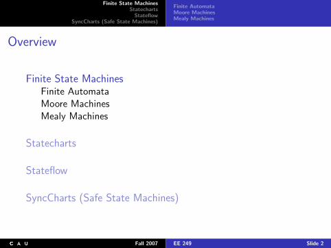
Finite Automata
Formally a finite automaton is defined as a five tuple(Q,Σ, δ, q0,F ) where
Q is a finite set of states,Σ is the input alphabet,q0 ∈ Q is the begin state (initial state),F ⊆ Q is the set of final states,δ : Q × Σ→ Q is the transition function.
The transition function gives for every state q and every inputsymbol a the new state δ(q, a) that arises as reaction on theexecution of a in state q.
Thanks to Willem-Paul de Roever and Kai Baukus for providing part of the following
material
Fall 2007 EE 249 Slide 3
Finite State MachinesStatecharts
StateflowSyncCharts (Safe State Machines)
Finite AutomataMoore MachinesMealy Machines
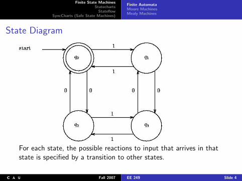
State Diagram
For each state, the possible reactions to input that arrives in thatstate is specified by a transition to other states.
Fall 2007 EE 249 Slide 4
Finite State MachinesStatecharts
StateflowSyncCharts (Safe State Machines)
Finite AutomataMoore MachinesMealy Machines
Extensions
I Restriction of these kind of automata as defined above: theyhave an input alphabet but not an output alphabet.
I There are two ways to extend the above model with output:
1. Output can be associated with a state (a so called Mooremachine)
2. or with a transition (a so called Mealy machine).
I A Moore machine is a 6-tuple (Q,Σ,∆, δ, λ, q0) whereQ,Σ, δ, q0 are the same as in the definition of the finiteautomaton,
∆ is the output alphabet andλ : Q → ∆ is the output function.
I A Mealy machine is also a 6-tuple (Q,Σ,∆, δ, λ, q0) but nowλ is a function from Q × Σ to ∆.
Fall 2007 EE 249 Slide 5
Finite State MachinesStatecharts
StateflowSyncCharts (Safe State Machines)
Finite AutomataMoore MachinesMealy Machines
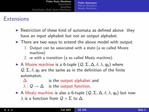
Example: Moore Machine
Ready
cup emitted
enter coin
Idle
enter coin
cup removed
action: initialize
Emitting cup
action: emit cup
Pouring coffee
action: pour coffee
I Moore machine: output λ is associated with every state
I Mealy machine: λ(q, a) gives output associated with thetransition of state q on input a.
Fall 2007 EE 249 Slide 6
Finite State MachinesStatecharts
StateflowSyncCharts (Safe State Machines)
Finite AutomataMoore MachinesMealy Machines
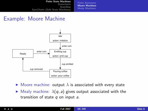
Serial Addition: Moore Machine
(1,0)
(1,1)
(0,0)
0 1
1
0
(1,1)
(0,0)(0,0)
(1,1)(0,0)
(1,0)
(0,1)
(1,1)
(1,0) or (0,1)
(0,1) or (1,0)
(0,1) or
carry: 0carry: 1
Fall 2007 EE 249 Slide 7
Finite State MachinesStatecharts
StateflowSyncCharts (Safe State Machines)
Finite AutomataMoore MachinesMealy Machines
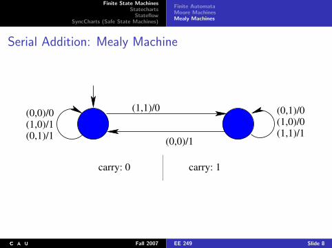
Serial Addition: Mealy Machine
(0,0)/0(1,0)/1(0,1)/1
(1,1)/0
(0,0)/1
(0,1)/0(1,0)/0(1,1)/1
carry: 0 carry: 1
Fall 2007 EE 249 Slide 8
Finite State MachinesStatecharts
StateflowSyncCharts (Safe State Machines)
Finite AutomataMoore MachinesMealy Machines
Disadvantages
I They have no structure. There is no strategy for theirtop-down or bottom-up development.
I State-transition diagrams are “flat”, i. e., without a naturalnotion of depth, hierarchy or modularity,
I State-transition diagrams are uneconomical concerning theirtransitions; think for instance of a high-level interrupt
Fall 2007 EE 249 Slide 9
Finite State MachinesStatecharts
StateflowSyncCharts (Safe State Machines)
Finite AutomataMoore MachinesMealy Machines
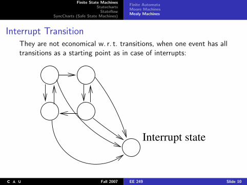
Interrupt TransitionThey are not economical w. r. t. transitions, when one event has alltransitions as a starting point as in case of interrupts:
Interrupt state
Fall 2007 EE 249 Slide 10
Finite State MachinesStatecharts
StateflowSyncCharts (Safe State Machines)
Finite AutomataMoore MachinesMealy Machines
Disadvantages (cont’d)
I Concerning the states, state-transition diagrams are even veryuneconomical: Exponential blow-up
I They are not economical w. r. t. parallel composition:Exponential growth in the number of states when composedin parallel.
I The nature of state-transition diagrams is inherently sequentialand so parallelism can‘t be represented in a natural way.
Fall 2007 EE 249 Slide 11
Finite State MachinesStatecharts
StateflowSyncCharts (Safe State Machines)
HierarchyOrthogonalityBroadcastTime in Statecharts
Overview
Finite State Machines
StatechartsHierarchyOrthogonalityBroadcastTime in Statecharts
Stateflow
SyncCharts (Safe State Machines)
Fall 2007 EE 249 Slide 12

Finite State MachinesStatecharts
StateflowSyncCharts (Safe State Machines)
HierarchyOrthogonalityBroadcastTime in Statecharts
Statecharts
I We need a formalism for the hierarchical development andrefinement of Mealy machines.
I This is provided by Statecharts, invented by David Harel(1987)
I Statecharts display hierarchy and structure, and enablehierarchical development
I In the following, will illustrate this with the example of atelevision set with remote control
I The Statecharts used in this lecture follow the syntax of theoriginal Statecharts, as invented by Harel, and as supported bythe STATEMATE toolset
Fall 2007 EE 249 Slide 13
Finite State MachinesStatecharts
StateflowSyncCharts (Safe State Machines)
HierarchyOrthogonalityBroadcastTime in Statecharts
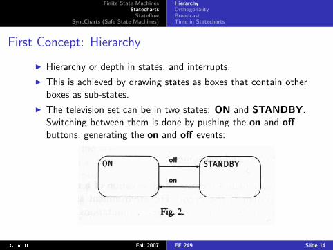
First Concept: Hierarchy
I Hierarchy or depth in states, and interrupts.
I This is achieved by drawing states as boxes that contain otherboxes as sub-states.
I The television set can be in two states: ON and STANDBY.Switching between them is done by pushing the on and offbuttons, generating the on and off events:
Fall 2007 EE 249 Slide 14
Finite State MachinesStatecharts
StateflowSyncCharts (Safe State Machines)
HierarchyOrthogonalityBroadcastTime in Statecharts
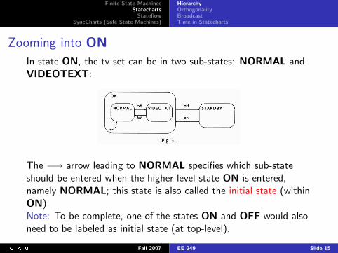
Zooming into ON
In state ON, the tv set can be in two sub-states: NORMAL andVIDEOTEXT:
The −→ arrow leading to NORMAL specifies which sub-stateshould be entered when the higher level state ON is entered,namely NORMAL; this state is also called the initial state (withinON)Note: To be complete, one of the states ON and OFF would alsoneed to be labeled as initial state (at top-level).
Fall 2007 EE 249 Slide 15
Finite State MachinesStatecharts
StateflowSyncCharts (Safe State Machines)
HierarchyOrthogonalityBroadcastTime in Statecharts
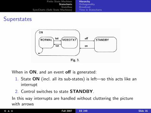
Superstates
When in ON, and an event off is generated:
1. State ON (incl. all its sub-states) is left—so this acts like aninterrupt
2. Control switches to state STANDBY.
In this way interrupts are handled without cluttering the picturewith arrows
Fall 2007 EE 249 Slide 16
Finite State MachinesStatecharts
StateflowSyncCharts (Safe State Machines)
HierarchyOrthogonalityBroadcastTime in Statecharts
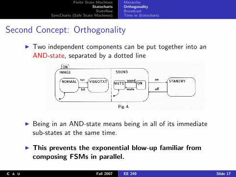
Second Concept: Orthogonality
I Two independent components can be put together into anAND-state, separated by a dotted line
I Being in an AND-state means being in all of its immediatesub-states at the same time.
I This prevents the exponential blow-up familiar fromcomposing FSMs in parallel.
Fall 2007 EE 249 Slide 17
Finite State MachinesStatecharts
StateflowSyncCharts (Safe State Machines)
HierarchyOrthogonalityBroadcastTime in Statecharts
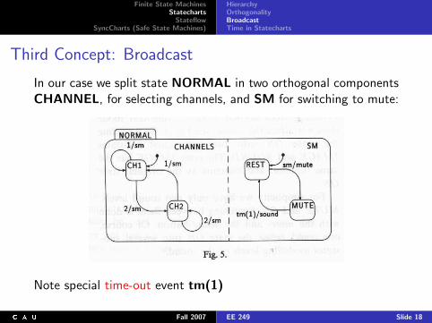
Third Concept: Broadcast
In our case we split state NORMAL in two orthogonal componentsCHANNEL, for selecting channels, and SM for switching to mute:
Note special time-out event tm(1)
Fall 2007 EE 249 Slide 18
Finite State MachinesStatecharts
StateflowSyncCharts (Safe State Machines)
HierarchyOrthogonalityBroadcastTime in Statecharts
Actions and Transitions
I Orthogonal components can communicate by generatingevents which are broadcast
I This can be done in a time-dependent manner: introducingthe generation of events e/a1; . . . ; an and time-out eventstm(1), . . .
I In general, the label of a transition consists of two parts:
1. Trigger, determininig if and when a transition will be taken2. Action, performed when a transition is taken.
I This action is the generation of a set of events.
Fall 2007 EE 249 Slide 19
Finite State MachinesStatecharts
StateflowSyncCharts (Safe State Machines)
HierarchyOrthogonalityBroadcastTime in Statecharts
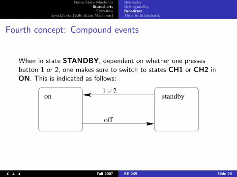
Fourth concept: Compound events
When in state STANDBY, dependent on whether one pressesbutton 1 or 2, one makes sure to switch to states CH1 or CH2 inON. This is indicated as follows:
off
1 2on standby
Fall 2007 EE 249 Slide 20

Finite State MachinesStatecharts
StateflowSyncCharts (Safe State Machines)
HierarchyOrthogonalityBroadcastTime in Statecharts
Transition Labels
I In general, one can label transitions by compound events suchas (¬a ∧ b) ∨ c , a ∧ b, c ∨ d , ¬a, etc.
I To express priority of event b over event a in this statechart:can replace a by a ∧ ¬b
Fall 2007 EE 249 Slide 21
Finite State MachinesStatecharts
StateflowSyncCharts (Safe State Machines)
HierarchyOrthogonalityBroadcastTime in Statecharts
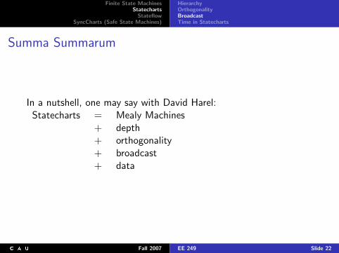
Summa Summarum
In a nutshell, one may say with David Harel:Statecharts = Mealy Machines
+ depth+ orthogonality+ broadcast+ data
Fall 2007 EE 249 Slide 22
Finite State MachinesStatecharts
StateflowSyncCharts (Safe State Machines)
HierarchyOrthogonalityBroadcastTime in Statecharts
Overview
Finite State Machines
StatechartsHierarchyOrthogonalityBroadcastTime in Statecharts
Stateflow
SyncCharts (Safe State Machines)
Fall 2007 EE 249 Slide 23
Finite State MachinesStatecharts
StateflowSyncCharts (Safe State Machines)
HierarchyOrthogonalityBroadcastTime in Statecharts
Characteristics of Real-Time Systems
I The environment can deliver data continuously, for examplevia temperature sensor.
I Data can be delivered from different sources simultaneouslyand must therefore be processed in parallel.
I The time scale is fast by human standard (milli secondsinstead of seconds),
I The system must react in time and accurately on input fromthe environment.
Fall 2007 EE 249 Slide 24
Finite State MachinesStatecharts
StateflowSyncCharts (Safe State Machines)
HierarchyOrthogonalityBroadcastTime in Statecharts
Time
I The elementary unit of observation in a reactive system is theevent
I The environment sends events to the system to triggercomputations, the system reacts to the environment bysending, or generating, events.
I Events are also means of communication between parts of asystem.
Fall 2007 EE 249 Slide 25
Finite State MachinesStatecharts
StateflowSyncCharts (Safe State Machines)
HierarchyOrthogonalityBroadcastTime in Statecharts
Time (cont’d)
I Because one wants to specify reactive systems at the highestlevel of abstraction in a discrete fashion, events are discretesignals, occurring at a point in time.
I Events have no duration; they are generated from one state toanother.
I Hence, transitions have a discrete uninterruptable nature andall time is spent in states.
Fall 2007 EE 249 Slide 26
Finite State MachinesStatecharts
StateflowSyncCharts (Safe State Machines)
HierarchyOrthogonalityBroadcastTime in Statecharts
Reason
In a reactive system new inputs may arrive at any moment.Therefore the current state it is in should be always clear. Sincetransitions have no duration, there are no “transient” periods inbetween states.Therefore, the reaction on a possible input is always well defined.
Of course this is an abstraction from reality. (At deeplevels of electronic implementations, one encounterslevels where discrete reasoning makes no sense anymore)
Statecharts is meant to be a high level specification language,where this abstraction can be maintained and is appropriate.
Fall 2007 EE 249 Slide 27
Finite State MachinesStatecharts
StateflowSyncCharts (Safe State Machines)
HierarchyOrthogonalityBroadcastTime in Statecharts
Reaction Time
I We know that transitions have no duration, but when do theytake place, relative to the trigger? And:
How long does it take the system to compute a reactionupon an external event?
I For transformational systems this is easy—the only importantdistinction is between finite and infinite values (correspondingto a final state or no final state)
I For reactive systems this is not enough:We have to know when an output occurs relative to theevents in the input sequence =⇒One has to determine the reaction time of a sequence.
Fall 2007 EE 249 Slide 28
Finite State MachinesStatecharts
StateflowSyncCharts (Safe State Machines)
HierarchyOrthogonalityBroadcastTime in Statecharts
Reaction Time in Statecharts
Question: What’s the reaction time of a reactive system upon anexternal event in Statecharts?
Possibility 1Specify a concrete amount of time for each situation.
I This forces us to quantify time right from the beginning.
I This is clumsy, and not appropriate at this stage ofspecification where one is only interested in the relative orderand coincidence of events.
Fall 2007 EE 249 Slide 29
Finite State MachinesStatecharts
StateflowSyncCharts (Safe State Machines)
HierarchyOrthogonalityBroadcastTime in Statecharts
Reaction Time in Statecharts
Question: What’s the reaction time of a reactive system upon anexternal event in Statecharts?
Possibility 2Fix reaction time between trigger a and corresponding action awithin e/a (the label of a transition) upon 1 time unit.
I Doesn’t work: Upon refining question/answer to aquestion/consult and a consult/answer transition, there’s achange of time, which may have far reaching consequences(e. g., because of tm(n)-events)
I =⇒ A fixed execution time for syntactic entities (transitions,statements, etc.) is not flexible enough.
Fall 2007 EE 249 Slide 30
Finite State MachinesStatecharts
StateflowSyncCharts (Safe State Machines)
HierarchyOrthogonalityBroadcastTime in Statecharts
Reaction Time in Statecharts
Question: What’s the reaction time of a reactive system upon anexternal event in Statecharts?
Possibility 3Leave things open
I Say only that execution of a reaction takes some positiveamount of time, and see at a later stage (closer to the actualimplementation) how much time things take.
I Clumsy, introduces far too much nondeterminism.
Fall 2007 EE 249 Slide 31
Finite State MachinesStatecharts
StateflowSyncCharts (Safe State Machines)
HierarchyOrthogonalityBroadcastTime in Statecharts
Solution
Summary: We want the execution time associated to reactions tohave following properties:
1. It should be accurate, but not depending on the actualimplementation.
2. It should be as short as possible, to avoid artificial delays.
3. It should be abstract in the sense that the timing behaviormust be orthogonal to the functional behavior.
=⇒ Only choice that meets all wishes is zero reaction time.
Fall 2007 EE 249 Slide 32
Finite State MachinesStatecharts
StateflowSyncCharts (Safe State Machines)
HierarchyOrthogonalityBroadcastTime in Statecharts
Problems Disappear
As a result all objections raised w. r. t. the possibilities mentionedon the previous page are met!
I Now, for instance, upon refining transition question/answerfrom previous page into two transitions, the reaction time ofthis refinement is the same as that of the original transition.
I Objection 3 on the previous transparency is resolved, too.
I Finally, also objection 1 (on previous transparency) is met,because 0 + 0 = 0!
Fall 2007 EE 249 Slide 33
Finite State MachinesStatecharts
StateflowSyncCharts (Safe State Machines)
HierarchyOrthogonalityBroadcastTime in Statecharts
Berry’s synchrony hypothesis
I This choice, that the reaction time between a trigger and itsevent is zero, is called Berry’s synchrony hypothesis.
I Is this implementable? No, a real computation takes time.
I However, in actual implementation this means:
The reaction comes before the next input arrives,
or, put another way,
Reactions are not infinitely fast, but fast enough.
Fall 2007 EE 249 Slide 34
Finite State MachinesStatecharts
StateflowSyncCharts (Safe State Machines)
HierarchyOrthogonalityBroadcastTime in Statecharts
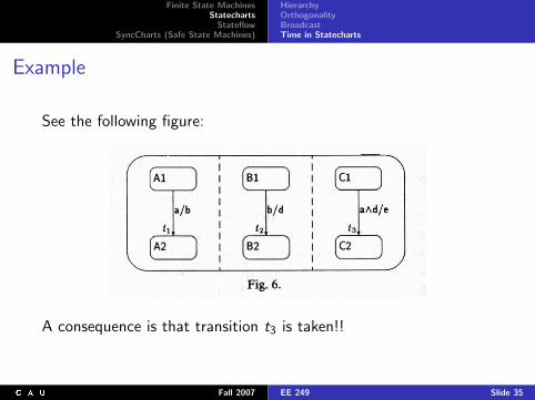
Example
See the following figure:
A consequence is that transition t3 is taken!!
Fall 2007 EE 249 Slide 35
Finite State MachinesStatecharts
StateflowSyncCharts (Safe State Machines)
HierarchyOrthogonalityBroadcastTime in Statecharts
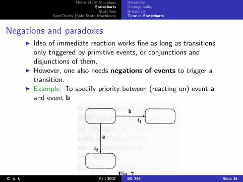
Negations and paradoxesI Idea of immediate reaction works fine as long as transitions
only triggered by primitive events, or conjunctions anddisjunctions of them.
I However, one also needs negations of events to trigger atransition.
I Example: To specify priority between (reacting on) event aand event b
Fall 2007 EE 249 Slide 36
Finite State MachinesStatecharts
StateflowSyncCharts (Safe State Machines)
HierarchyOrthogonalityBroadcastTime in Statecharts
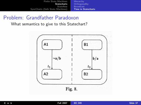
Problem: Grandfather ParadoxonWhat semantics to give to this Statechart?
Fall 2007 EE 249 Slide 37
Finite State MachinesStatecharts
StateflowSyncCharts (Safe State Machines)
HierarchyOrthogonalityBroadcastTime in Statecharts
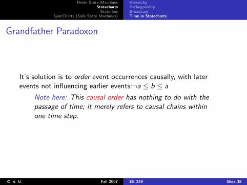
Grandfather Paradoxon
It’s solution is to order event occurrences causally, with laterevents not influencing earlier events:¬a ≤ b ≤ a
Note here: This causal order has nothing to do with thepassage of time; it merely refers to causal chains withinone time step.
Fall 2007 EE 249 Slide 38
Finite State MachinesStatecharts
StateflowSyncCharts (Safe State Machines)
HierarchyOrthogonalityBroadcastTime in Statecharts
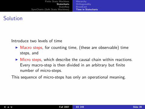
Solution
Introduce two levels of time
I Macro steps, for counting time, (these are observable) timesteps, and
I Micro steps, which describe the causal chain within reactions.Every macro-step is then divided in an arbitrary but finitenumber of micro-steps.
This sequence of micro-steps has only an operational meaning.
Fall 2007 EE 249 Slide 39
Finite State MachinesStatecharts
StateflowSyncCharts (Safe State Machines)
HierarchyOrthogonalityBroadcastTime in Statecharts
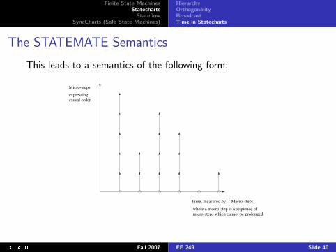
The STATEMATE Semantics
This leads to a semantics of the following form:
Micro-steps
expressingcausal order
Time, measured by Macro-steps,
where a macro-step is a sequence ofmicro-steps which cannot be prolonged
Fall 2007 EE 249 Slide 40
Finite State MachinesStatecharts
StateflowSyncCharts (Safe State Machines)
HierarchyOrthogonalityBroadcastTime in Statecharts
The STATEMATE Semantics (cont’d)
I Macro-steps are observable steps =⇒OI
I Each macro-step is a sequence of micro-steps, that is orderedcausally; one micro-step can never influence previousmicro-steps.
I In Statecharts as implemented by STATEMATE(“Harel-Statecharts”):
I Causality is trivially obtained because in STATEMATE eventsgenerated in one step are only available in the next step, andonly for that one.
I I. e., there is no causality within one step.
Fall 2007 EE 249 Slide 41
Finite State MachinesStatecharts
StateflowSyncCharts (Safe State Machines)
HierarchyOrthogonalityBroadcastTime in Statecharts
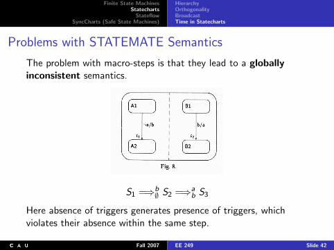
Problems with STATEMATE Semantics
The problem with macro-steps is that they lead to a globallyinconsistent semantics.
S1 =⇒b∅ S2 =⇒a
b S3
Here absence of triggers generates presence of triggers, whichviolates their absence within the same step.
Fall 2007 EE 249 Slide 42
Finite State MachinesStatecharts
StateflowSyncCharts (Safe State Machines)
Simulink InterfaceSemantics
Overview
Finite State Machines
Statecharts
StateflowSimulink InterfaceSemantics
SyncCharts (Safe State Machines)
Fall 2007 EE 249 Slide 43
Finite State MachinesStatecharts
StateflowSyncCharts (Safe State Machines)
Simulink InterfaceSemantics
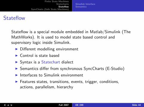
Stateflow
Stateflow is a special module embedded in Matlab/Simulink (TheMathWorks). It is used to model state based control andsupervisory logic inside Simulink.
I Different modelling environment
I Control is state based
I Syntax is a Statechart dialect
I Semantics differ from synchronous SyncCharts (E-Studio)
I Interfaces to Simulink environment
I Features states, transitions, events, trigger, conditions,actions, parallelism, hierarchy
Fall 2007 EE 249 Slide 44
Finite State MachinesStatecharts
StateflowSyncCharts (Safe State Machines)
Simulink InterfaceSemantics
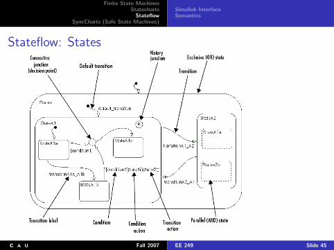
Stateflow: States
Fall 2007 EE 249 Slide 45
Finite State MachinesStatecharts
StateflowSyncCharts (Safe State Machines)
Simulink InterfaceSemantics
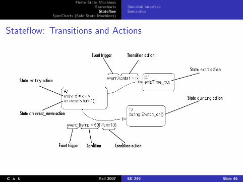
Stateflow: Transitions and Actions
Fall 2007 EE 249 Slide 46

Finite State MachinesStatecharts
StateflowSyncCharts (Safe State Machines)
Simulink InterfaceSemantics
Simulink InterfaceStateflow Charts can be embedded into Simulink models.
Stateflow distinguishes: Data (only values) and Events (onlyboolean signals). Stateflow charts get evaluated only either at
I events: Data changes are only detected if some other eventhappened (if no external event occurs, the chart is notevaluated)
I predefined sample time: Chart is evaluated regularly: Alsodata changes are detected. No external event inputs allowed.
Fall 2007 EE 249 Slide 47
Finite State MachinesStatecharts
StateflowSyncCharts (Safe State Machines)
Simulink InterfaceSemantics
Stateflow Semantics
I Stateflow semantics are not formally specified, only informallyby Stateflow manual.
I Single-Event run-to-completion semantics
I Exactly one event is evaluated when it occurs
⇒ Triggers with multiple concurrent events (e. g. “A and B”) arenot possible (only disjunction is possible, using the ORoperator: “A ‖ B”)
⇒ Negation of events (e. g. “not A”) is not possible
I Parallel states are evaluated by some predefined executionorder, depending on graphical layout/user input (see nextslide)
Fall 2007 EE 249 Slide 48
Finite State MachinesStatecharts
StateflowSyncCharts (Safe State Machines)
Simulink InterfaceSemantics
Events and Actions
Event When event occurs
I it is processed from the top or root of the diagram downthrough the hierarchy.
I At each level in the hierarchy a check for the existence of avalid explicit or implicit transition among the children of thestate is conducted.
Condition Action I Executed as soon as the condition is evaluated as true,I but before the transition destination has been determined to
be valid.I No condition =⇒ an implied condition evaluates to true and
the condition action is executed
Transition Actions I Executed when the transition is actually taken:I Executed after the transition destination has been determined
to be validI and the condition, if specified, is trueI Consists of multiple segments =⇒ only executed when the
entire transition path to the final destination is valid
Fall 2007 EE 249 Slide 49
Finite State MachinesStatecharts
StateflowSyncCharts (Safe State Machines)
Simulink InterfaceSemantics
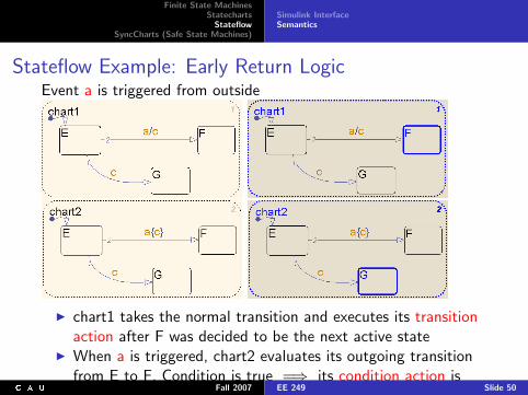
Stateflow Example: Early Return LogicEvent a is triggered from outside
I chart1 takes the normal transition and executes its transitionaction after F was decided to be the next active state
I When a is triggered, chart2 evaluates its outgoing transitionfrom E to F. Condition is true =⇒ its condition action isexecuted immediately and especially while E is still the activestate. Now event c is handled while E is still active andtherefore the transition from E to G is finally taken.
Fall 2007 EE 249 Slide 50
Finite State MachinesStatecharts
StateflowSyncCharts (Safe State Machines)
Simulink InterfaceSemantics
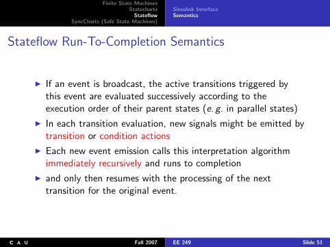
Stateflow Run-To-Completion Semantics
I If an event is broadcast, the active transitions triggered bythis event are evaluated successively according to theexecution order of their parent states (e. g. in parallel states)
I In each transition evaluation, new signals might be emitted bytransition or condition actions
I Each new event emission calls this interpretation algorithmimmediately recursively and runs to completion
I and only then resumes with the processing of the nexttransition for the original event.
Fall 2007 EE 249 Slide 51
Finite State MachinesStatecharts
StateflowSyncCharts (Safe State Machines)
Simulink InterfaceSemantics
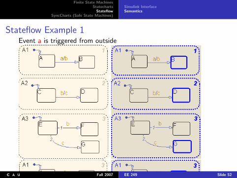
Stateflow Example 1Event a is triggered from outside
Fall 2007 EE 249 Slide 52
Finite State MachinesStatecharts
StateflowSyncCharts (Safe State Machines)
Simulink InterfaceSemantics
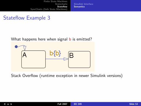
Stateflow Example 3
What happens here when signal b is emitted?
Stack Overflow (runtime exception in newer Simulink versions)
Fall 2007 EE 249 Slide 53
Finite State MachinesStatecharts
StateflowSyncCharts (Safe State Machines)
StatesTransitionsConnectorsEsterel Studio
Overview
Finite State Machines
Statecharts
Stateflow
SyncCharts (Safe State Machines)StatesTransitionsConnectorsEsterel Studio
Fall 2007 EE 249 Slide 54
Finite State MachinesStatecharts
StateflowSyncCharts (Safe State Machines)
StatesTransitionsConnectorsEsterel Studio
Similarities
SyncCharts are made up of elements common to most Statechartsdialects:
I States
I Initial/terminal states
I Transitions
I Signals/Events
I Hierarchy
I Modularity
I Parallelism
Fall 2007 EE 249 Slide 55
Finite State MachinesStatecharts
StateflowSyncCharts (Safe State Machines)
StatesTransitionsConnectorsEsterel Studio
Differences
SyncCharts differ from other implementations of Statecharts:
I Synchronous framework
I Determinism
I Compilation into backend language Esterel
I No interpretation for simulations
I No hidden behaviour
I Multiple events
I Negation of events
I No inter-level transitions
Fall 2007 EE 249 Slide 56
Finite State MachinesStatecharts
StateflowSyncCharts (Safe State Machines)
StatesTransitionsConnectorsEsterel Studio
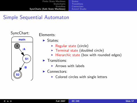
Simple Sequential Automaton
SyncChart:
main
S2
S1
I
/B
/A
Elements:I States:
I Regular state (circle)I Terminal state (doubled circle)I Hierarchic state (box with rounded edges)
I Transitions:I Arrows with labels
I Connectors:I Colored circles with single letters
Fall 2007 EE 249 Slide 57
Finite State MachinesStatecharts
StateflowSyncCharts (Safe State Machines)
StatesTransitionsConnectorsEsterel Studio
Hierarchic States
main_hier
I
S0
T
Graphic Macrostate
S1Textual Macrostate
I HS1
HS2HS3
HS4 HT
<2><1>
emit B;if ?A = 3 then emit Dend;await C
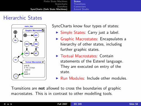
SyncCharts know four types of states:
I Simple States: Carry just a label.
I Graphic Macrostates: Encapsulates ahierarchy of other states, includingfurther graphic states.
I Textual Macrostates: Containstatements of the Esterel language.They are executed on entry of thestate.
I Run Modules: Include other modules.
Transitions are not allowed to cross the boundaries of graphicmacrostates. This is in contrast to other modelling tools.
Fall 2007 EE 249 Slide 58
Finite State MachinesStatecharts
StateflowSyncCharts (Safe State Machines)
StatesTransitionsConnectorsEsterel Studio
Parallel States
main_parallel
I
Wait for A
I
A/
I
Wait for B
B/
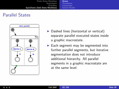
I Dashed lines (horizontal or vertical)separate parallel executed states insidea graphic macrostate.
I Each segment may be segmented intofurther parallel segments, but iterativesegmentation does not introduceadditional hierarchy. All parallelsegments in a graphic macrostate areat the same level.
Fall 2007 EE 249 Slide 59
Finite State MachinesStatecharts
StateflowSyncCharts (Safe State Machines)
StatesTransitionsConnectorsEsterel Studio
Parallel States
main_parallel
I
Wait for A
I
A/
I
Wait for B
B/
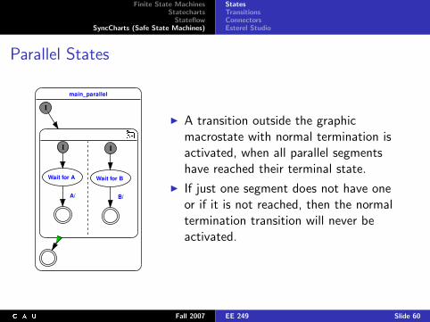
I A transition outside the graphicmacrostate with normal termination isactivated, when all parallel segmentshave reached their terminal state.
I If just one segment does not have oneor if it is not reached, then the normaltermination transition will never beactivated.
Fall 2007 EE 249 Slide 60
Finite State MachinesStatecharts
StateflowSyncCharts (Safe State Machines)
StatesTransitionsConnectorsEsterel Studio
Modules
m
I
I/O
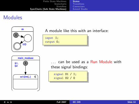
A module like this with an interface:
input I;
output O;
main_moduse
S1,S2
I
m1@m[..]
. . . can be used as a Run Module withthese signal bindings:
signal S1 / I;
signal S2 / O
Fall 2007 EE 249 Slide 61
Finite State MachinesStatecharts
StateflowSyncCharts (Safe State Machines)
StatesTransitionsConnectorsEsterel Studio
Syntax of Transition Labelsmain_trans
S2S1
I..Label
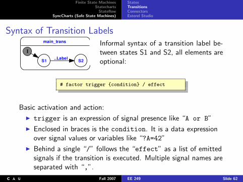
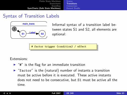
Informal syntax of a transition label be-tween states S1 and S2, all elements areoptional:
# factor trigger {condition} / effect
Basic activation and action:
I trigger is an expression of signal presence like “A or B”
I Enclosed in braces is the condition. It is a data expressionover signal values or variables like “?A=42”
I Behind a single “/” follows the “effect” as a list of emittedsignals if the transition is executed. Multiple signal names areseparated with “,”.
Fall 2007 EE 249 Slide 62
Finite State MachinesStatecharts
StateflowSyncCharts (Safe State Machines)
StatesTransitionsConnectorsEsterel Studio
Syntax of Transition Labels
main_trans
S2S1
I..Label
Informal syntax of a transition label be-tween states S1 and S2, all elements areoptional:
# factor trigger {condition} / effect
Extensions:
I “#” is the flag for an immediate transition
I “factor” is the (natural) number of instants a transitionmust be active before it is executed. These active instantsdoes not need to be consecutive, but S1 must be active all thetime.
Fall 2007 EE 249 Slide 63
Finite State MachinesStatecharts
StateflowSyncCharts (Safe State Machines)
StatesTransitionsConnectorsEsterel Studio
Transition Labels: Examplesmain_trans
S2S1
I..Label
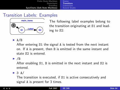
The following label examples belong tothe transition originating at S1 and lead-ing to S2:
I A/BAfter entering S1 the signal A is tested from the next instanton. If A is present, then B is emitted in the same instant andstate S2 is entered.
I /BAfter enabling S1, B is emitted in the next instant and S2 isentered.
I 3 A/The transition is executed, if S1 is active consecutively andsignal A is present for 3 times.
Fall 2007 EE 249 Slide 64
Finite State MachinesStatecharts
StateflowSyncCharts (Safe State Machines)
StatesTransitionsConnectorsEsterel Studio
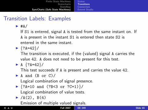
Transition Labels: ExamplesI #A/
If S1 is entered, signal A is tested from the same instant on. IfA is present in the instant S1 is entered then state S2 isentered in the same instant.
I {?A=42}/The transition is executed, if the (valued) signal A carries thevalue 42. A does not need to be present for this test.
I A {?A=42}/This test succeeds if A is present and carries the value 42.
I A and (B or C)/Logical combination of signal presence.
I {?A=10 and (?B<3 or ?C=1)}/Logical combination of value tests.
I /A(2), B(4)Emission of multiple valued signals.
Fall 2007 EE 249 Slide 65
Finite State MachinesStatecharts
StateflowSyncCharts (Safe State Machines)
StatesTransitionsConnectorsEsterel Studio
Transition Priorities
main_prio
I
S0
S2
B/<2>
S1
S3
A/<1>
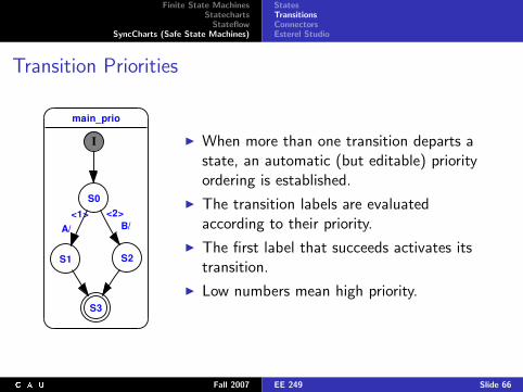
I When more than one transition departs astate, an automatic (but editable) priorityordering is established.
I The transition labels are evaluatedaccording to their priority.
I The first label that succeeds activates itstransition.
I Low numbers mean high priority.
Fall 2007 EE 249 Slide 66
Finite State MachinesStatecharts
StateflowSyncCharts (Safe State Machines)
StatesTransitionsConnectorsEsterel Studio
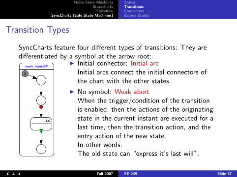
Transition Types
SyncCharts feature four different types of transitions: They aredifferentiated by a symbol at the arrow root:
main_transdiff
I
I Initial connector: Initial arcInitial arcs connect the initial connectors ofthe chart with the other states.
I No symbol: Weak abortWhen the trigger/condition of the transitionis enabled, then the actions of the originatingstate in the current instant are executed for alast time, then the transition action, and theentry action of the new state.In other words:The old state can “express it’s last will”.
Fall 2007 EE 249 Slide 67
Finite State MachinesStatecharts
StateflowSyncCharts (Safe State Machines)
StatesTransitionsConnectorsEsterel Studio
Transition Types
main_transdiff
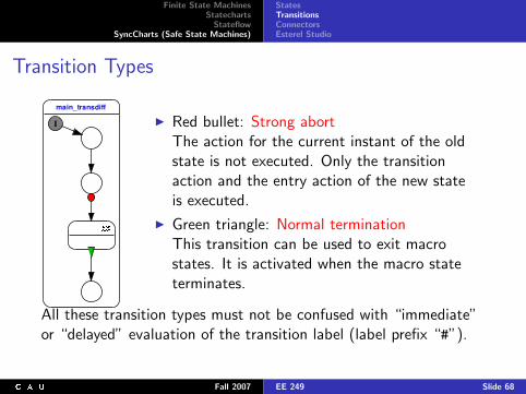
I I Red bullet: Strong abortThe action for the current instant of the oldstate is not executed. Only the transitionaction and the entry action of the new stateis executed.
I Green triangle: Normal terminationThis transition can be used to exit macrostates. It is activated when the macro stateterminates.
All these transition types must not be confused with “immediate”or “delayed” evaluation of the transition label (label prefix “#”).
Fall 2007 EE 249 Slide 68
Finite State MachinesStatecharts
StateflowSyncCharts (Safe State Machines)
StatesTransitionsConnectorsEsterel Studio
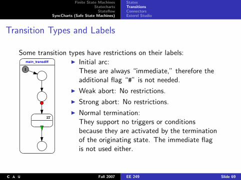
Transition Types and Labels
Some transition types have restrictions on their labels:main_transdiff
I
I Initial arc:These are always “immediate,” therefore theadditional flag “#” is not needed.
I Weak abort: No restrictions.
I Strong abort: No restrictions.
I Normal termination:They support no triggers or conditionsbecause they are activated by the terminationof the originating state. The immediate flagis not used either.
Fall 2007 EE 249 Slide 69
Finite State MachinesStatecharts
StateflowSyncCharts (Safe State Machines)
StatesTransitionsConnectorsEsterel Studio
Transition Types and Priorities
The type of a transition interacts with it’s priority:
I Strong abort: Highest priority
I Weak abort: Middle priority
I Normal termination: Lowest priority
Esterel Studio enforces these rules by changing the numericalpriorities of the transitions.
Fall 2007 EE 249 Slide 70
Finite State MachinesStatecharts
StateflowSyncCharts (Safe State Machines)
StatesTransitionsConnectorsEsterel Studio
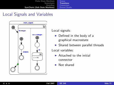
Local Signals and Variables
main_signal
I
II
B/A/B(20)
var c:integer
B:integer
c := 30;
Local signals:
I Defined in the body of agraphical macrostate
I Shared between parallel threads
Local variables:
I Attached to the initialconnector
I Not shared
Fall 2007 EE 249 Slide 71
Finite State MachinesStatecharts
StateflowSyncCharts (Safe State Machines)
StatesTransitionsConnectorsEsterel Studio
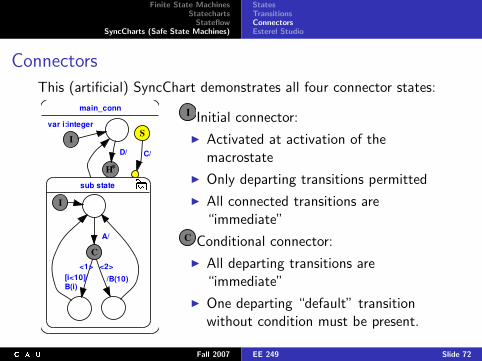
Connectors
This (artificial) SyncChart demonstrates all four connector states:
main_conn
sub state
S
C/
I
var i:integer
H*
D/
I
C
A/
/B(10)
<2>[i<10]/B(i)
<1>
main_conn
sub state
S
C/
I
var i:integer
H*
D/
I
C
A/
/B(10)
<2>[i<10]/B(i)
<1>
Initial connector:
I Activated at activation of themacrostate
I Only departing transitions permitted
I All connected transitions are“immediate”
main_conn
sub state
S
C/
I
var i:integer
H*
D/
I
C
A/
/B(10)
<2>[i<10]/B(i)
<1>Conditional connector:
I All departing transitions are“immediate”
I One departing “default” transitionwithout condition must be present.
Fall 2007 EE 249 Slide 72
Finite State MachinesStatecharts
StateflowSyncCharts (Safe State Machines)
StatesTransitionsConnectorsEsterel Studio
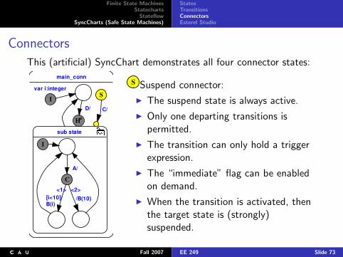
Connectors
This (artificial) SyncChart demonstrates all four connector states:
main_conn
sub state
S
C/
I
var i:integer
H*
D/
I
C
A/
/B(10)
<2>[i<10]/B(i)
<1>
main_conn
sub state
S
C/
I
var i:integer
H*
D/
I
C
A/
/B(10)
<2>[i<10]/B(i)
<1>
Suspend connector:
I The suspend state is always active.
I Only one departing transitions ispermitted.
I The transition can only hold a triggerexpression.
I The “immediate” flag can be enabledon demand.
I When the transition is activated, thenthe target state is (strongly)suspended.
Fall 2007 EE 249 Slide 73
Finite State MachinesStatecharts
StateflowSyncCharts (Safe State Machines)
StatesTransitionsConnectorsEsterel Studio
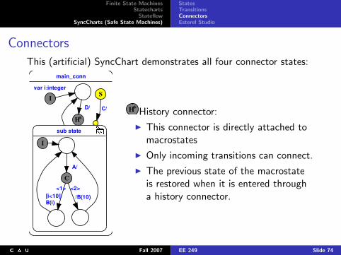
Connectors
This (artificial) SyncChart demonstrates all four connector states:
main_conn
sub state
S
C/
I
var i:integer
H*
D/
I
C
A/
/B(10)
<2>[i<10]/B(i)
<1>
main_conn
sub state
S
C/
I
var i:integer
H*
D/
I
C
A/
/B(10)
<2>[i<10]/B(i)
<1>
History connector:
I This connector is directly attached tomacrostates
I Only incoming transitions can connect.
I The previous state of the macrostateis restored when it is entered througha history connector.
Fall 2007 EE 249 Slide 74
Finite State MachinesStatecharts
StateflowSyncCharts (Safe State Machines)
StatesTransitionsConnectorsEsterel Studio
Esterel Studio
http://www.esterel-technologies.com/
Esterel Studio features:
I Graphical editor for Statechart dialect “Safe State Machines”,a. k. a. SyncCharts
I Code generator for textual Esterel
I Esterel compiler for C code production
I Interface to backend in host language (C)
I Graphical simulation Validation/Testing environment
Fall 2007 EE 249 Slide 75
Finite State MachinesStatecharts
StateflowSyncCharts (Safe State Machines)
StatesTransitionsConnectorsEsterel Studio
To Go FurtherI David Harel, Statecharts: A Visual Formulation for Complex
Systems, Science of Computer Programming, 8(3), June1987, pp. 231–274
I D. Harel, M, Politi, Modeling Reactive Systems withStatecharts: The STATEMATE Approach, McGraw-Hill, ISBN0-07-026205-5, 1998.
I Charles Andr, Semantics of S.S.M (Safe State Machine),Esterel Technologies Technical Report, April, 2003,http://www.esterel-technologies.com/v3/?id=50399&dwnID=48
I Home page of Esterel Technologies:http://www.esterel-technologies.com/
I Local information on Esterel-Studio and where to find furtherdocumentation:http://www.informatik.uni-kiel.de/~esterel/
Fall 2007 EE 249 Slide 76


![INSTITUT F UR INFORMATIK¨rtsys.informatik.uni-kiel.de/~biblio/downloads/papers/report-1006.pdf · the compilation from SyncCharts to KEP assembler [12]. However, the abortion scheme](https://img.pdfslide.us/doc/110x75/5dd0de17d6be591ccb63168a/institut-f-ur-informatikrtsys-bibliodownloadspapersreport-1006pdf-the-compilation.jpg)