Embed Size (px)
Citation preview

613
Proceedings of the XVI ECSMGEGeotechnical Engineering for Infrastructure and DevelopmentISBN 978-0-7277-6067-8
© The authors and ICE Publishing: All rights reserved, 2015doi:10.1680/ecsmge.60678
increased, more realistic cohesion for the claystone of c’ = 200 kPa instead of the more conservative characteristic value of 50 kPa from the expert soil re-port is used. Additionally the measurements are in-fluenced by seasonal temperature changes which are not taken into account in the calculation.
Exemplary vertical (temperature-corrected) de-formations of the shaft lock chamber are depicted in Fig. 10. The settlements of the lock started with the beginning of dewatering and amount to 3 mm on the side facing the excavation and 5 mm on the other side. A tilting of the shaft lock was also captured by the FE model, even though the calculated differential settlement was smaller. FE calculation results reveal that the tilting occurs due to the groundwater lower-ing which caused higher settlements on the western side of the shaft lock.
Figure 10. Vertical deformations at the chamber of the shaft lock
Following the excavation increasing heave defor-
mations were measured at the bottom of the pit in three different depths (see Fig. 2). The measured val-ues are depicted in Fig. 11.
Owing to the ongoing solid construction works of the new lock in 2013, the applied load on the ground leads visibly to opposite deformations (settlement). The calculated heave at the pit bottom is much lower (max. 4 mm at the final excavation stage in July 2012) than the measured values (max. 23 mm). The
disproportionally high increase of heave can be inter-preted as an effect of an excavation damaged zone in the claystone, which spread underneath the pit bot-tom due to excavation works.
Figure 11. Measured heave of the pit bottom
6 CONCLUSION
The objective of minimizing the risk during the ex-cavation was achieved by means of the established measurement concept. No critical pressure, inflow rate or deformations were observed. The Minden lock excavation proved that the combination of de-tailed observations and simultaneous FE-modelling is a valuable tool to understand and assess interactions between structure, soil and groundwater considering the immediate vicinity of existing structures and the ongoing navigation.
REFERENCES
EAB 2008. Recommendations on Excavations, 2nd edition, pub-lished by the German Geotechnical Society Kauther, R., Herten, M., Montenegro, H. & Odenwald, B. 2013. Geotechnische und geohydraulische Aspekte beim Bau der Weser-schleuse in Minden. GEOTECHNIK, 03/2013: WILEY. Mikkelsen, P. 2003. Advances in Inclinometer Data Analysis, Symposium on Field Measurements in Geomechanics, FMGM 2003, Oslo, Norway, September 2003 Montenegro, H. & Kauther, R. 2010. A Multi-Scale Approach for the Consideration of Spatial Groundwater Flow in the Stability Analysis of a Large Excavation Pit. 7th Europ. Conf. on Numerical Methods in Geotechnical Engineering NUMGE 2010, June 2-4, 2010. Trondheim, Norway.
Design of deep excavations under consideration of spatial earth pressure
Dimensionnement de basses excavations considérant la pression spatiale du sol active
L. Klein*1 and C. Moormann1 1 University of Stuttgart, Institute of Geotechnics, Stuttgart, Germany
* Corresponding Author
ABSTRACT The spatial support and deformation behavior of excavations with rectangular plan is characterized by an increase of defor-mations of the retaining walls and ground surface along the side walls with increasing distance from the excavation corners. Large-scalestress arches in the soil continuum lead to stress concentrations in the area of the excavation corners. In the engineering practice these ef-fects are usually not taken into account in the approach of the displacement dependent earth pressure, even though a technically and eco-nomically optimized design of the excavation structure could be achieved. The investigation of spatial active earth pressure on excavationsof rectangular shape and varying system stiffness of the retaining walls is subject of an ongoing research project.
RÉSUMÉ Le comportement spatial du support et des déformations d’excavations de base rectangulaire est caractérisé par des déforma-tions de plus en plus importantes des parois et de la surface du sol, le long des parois, lorsque l’on s’éloigne des coins de l ́excavation. Onnote également que des concentrations de tensions se forment dans les coins ce qui a pour conséquence que de vastes voûtes de tension ap-paraissent dans la continuité du sol. Ces effets ne sont généralement pas pris en compte dans la pratique d'ingénierie à l'approche de la pres-sion du sol, dépendante du déplacement de sol, alors qu'une conception techniquement et économiquement optimisée de la structure del'excavation pourrait être atteinte. L'enquête sur la pression spatiale active du sol, lors d’excavations de base rectangulaire et de rigidité va-riable des parois, fait l'objet d'un projet de recherche en cours.
1 INTRODUCTION
Excavations with a rectangular plan represent the most frequently applied form. In the design of the re-taining walls usually vertical plane strain sections are considered by applying the plane active earth pres-sure. This procedure neglects that the excavation in-duced formation of large horizontal stress arches sur-rounding the construction pit significantly influence the distribution of earth pressure along the retaining walls. Excavations are basically spatial structural sys-tems due to their ground plan, the support system, the progress of the excavation process and varying ge-otechnical conditions. The consideration of spatial active earth pressure enables a more economical de-sign of structural components as well as a more real-istic deformation forecast.
2 DEFORMATION BEHAVIOUR OF EXCA-VATIONS WITH RECTANGULAR PLAN
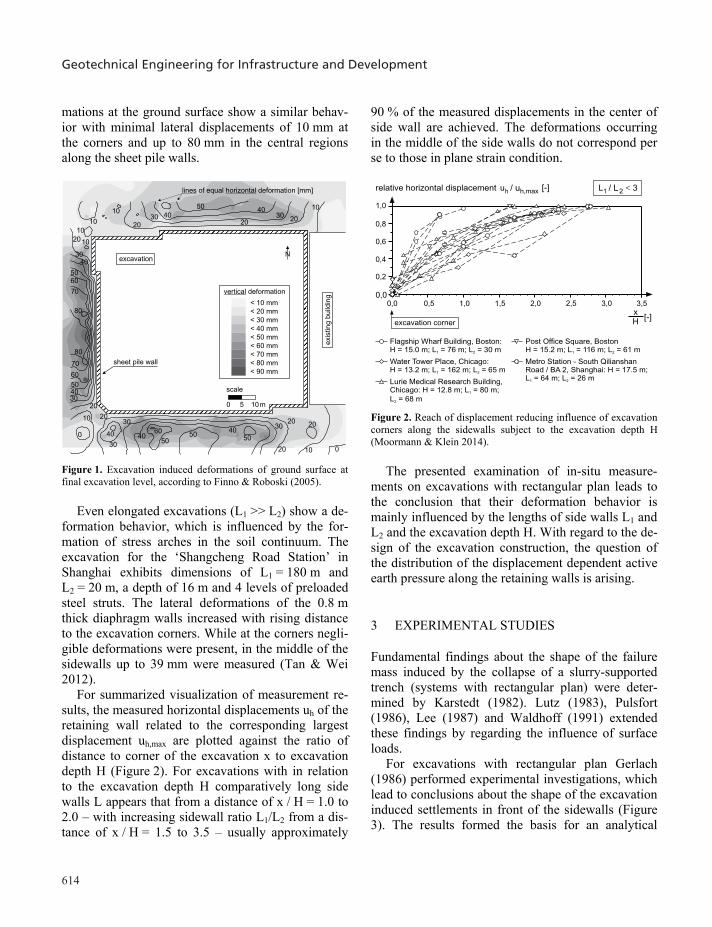
As first case study the excavation for the ‘Lurie Med-ical Research Building’ in Chicago with a depth of 12.8 m and nearly rectangular plan with dimensions of L1 = 80 m and L2 = 68 m is regarded. The subsoil is dominated by a sand layer underlain by soft to stiff glacial clays with increasing shear strength with depth. The excavation was supported by an 18 m deep sheet pile wall and two resp. three levels of ground anchors. Finno & Roboski (2005) report that the excavation induced settlements at the ground sur-face increased from very slight deformations of ap-proximately 10 mm in the region of the corners of the excavation to up to 80 mm in the middle sections of the retaining walls (Figure 1). The horizontal defor-
Geotechnical Engineering for Infrastructure and Development
614
mations at the ground surface show a similar behav-ior with minimal lateral displacements of 10 mm at the corners and up to 80 mm in the central regions along the sheet pile walls.
exis
ting
build
ing
scale
1050 m
Nexcavation
10
5050 5040
4040
20
20
20
3030
30
60
5040
2030
60
70
80
0
10
20
0
50
4030
60
70
80
2010
20
2020
50 4030
10
104030
10
10
vertical deformation
< 10 mm
< 20 mm
< 30 mm
< 40 mm
< 50 mm
< 60 mm
< 70 mm
< 80 mm
< 90 mm
lines of equal deformationhorizontal [mm]
sheet pile wall
Figure 1. Excavation induced deformations of ground surface at final excavation level, according to Finno & Roboski (2005).
Even elongated excavations (L1 >> L2) show a de-formation behavior, which is influenced by the for-mation of stress arches in the soil continuum. The excavation for the ‘Shangcheng Road Station’ in Shanghai exhibits dimensions of L1 = 180 m and L2 = 20 m, a depth of 16 m and 4 levels of preloaded steel struts. The lateral deformations of the 0.8 m thick diaphragm walls increased with rising distance to the excavation corners. While at the corners negli-gible deformations were present, in the middle of the sidewalls up to 39 mm were measured (Tan & Wei 2012).
For summarized visualization of measurement re-sults, the measured horizontal displacements uh of the retaining wall related to the corresponding largest displacement uh,max are plotted against the ratio of distance to corner of the excavation x to excavation depth H (Figure 2). For excavations with in relation to the excavation depth H comparatively long side walls L appears that from a distance of x / H = 1.0 to 2.0 – with increasing sidewall ratio L1/L2 from a dis-tance of x / H = 1.5 to 3.5 – usually approximately
90 % of the measured displacements in the center of side wall are achieved. The deformations occurring in the middle of the side walls do not correspond per se to those in plane strain condition.
Post Office Square, BostonH = 15.2 m; L = 116 m; L = 61 m1 2
Flagship Wharf Building, Boston:H = 15.0 m; L = 76 m; L = 30 m1 2
Water Tower Place, Chicago:H = 13.2 m; L = 162 m; L = 65 m1 2
Lurie Medical Research Building,Chicago: H = 12.8 m; L = 80 m;
L = 68 m1
2
0,00,0
0,2
0,4
0,6
0,8
1,0
0,5 1,0 1,5 2,0 2,5 3,0
xH
[-]
relative horizontal displacement [-]u uh h,max/
excavation corner
3,5
Metro Station - South QilianshanRoad / , Shanghai: H = 17.5 m;L = 64 m; L = 26 m1 2
BA 2
� 3L L1 2/
Figure 2. Reach of displacement reducing influence of excavation corners along the sidewalls subject to the excavation depth H (Moormann & Klein 2014).
The presented examination of in-situ measure-ments on excavations with rectangular plan leads to the conclusion that their deformation behavior is mainly influenced by the lengths of side walls L1 and L2 and the excavation depth H. With regard to the de-sign of the excavation construction, the question of the distribution of the displacement dependent active earth pressure along the retaining walls is arising.
3 EXPERIMENTAL STUDIES
Fundamental findings about the shape of the failure mass induced by the collapse of a slurry-supported trench (systems with rectangular plan) were deter-mined by Karstedt (1982). Lutz (1983), Pulsfort (1986), Lee (1987) and Waldhoff (1991) extended these findings by regarding the influence of surface loads.
For excavations with rectangular plan Gerlach (1986) performed experimental investigations, which lead to conclusions about the shape of the excavation induced settlements in front of the sidewalls (Figure 3). The results formed the basis for an analytical
method to determinate the spatial active earth pres-sure, compare chapter 4.
40°48°
rotation about the base of the wall
parallel displacement of the wall
45°55°
L1
2.0 0.661.01.331.51.75excavation depth H
side wall length L1
L1
H
H
Figure 3. Idealized traces of failure mass at the surface of the soil, according to Gerlach (1986).
Experimental investigations on plane structural el-ements of limited dimensions (variation of the ratio of element height H to side wall length L1 between 2 and 8 - shaft-like structures) were performed by tom Wörden (2010). It was found that subject to the wall deformation mode, the measured resultant of the spa-tial active earth pressure is up to 82 % less than the resultant of the plane active earth pressure. In case of a ratio of element height to side wall length of H/L1 = 3 results an increase of horizontal stresses up to a distance of 0.5 to 1 L beside the active dis-placed element.
No conclusions on the distribution of spatial active earth pressure along the sidewalls of excavations with rectangular shape can be drawn on the basis of the experimental investigations reported in literature.
4 ANALYTICAL METHODS
The analytical methods for the determination of the spatial active earth pressure acting on slurry-supported trenches and sidewalls of limited lengths can basically be divided into two groups (Figure 4). The static methods consider a completely plasticized
soil mass adjacent to the sidewall and an activation of shear forces in the corresponding interfaces. The consequently reduced vertical stresses are considered for the calculation of spatial active earth pressure. In contrast, the kinematic methods regard the equilibri-um of a geometrically defined failure mass to deter-mine the resultant of the spatial active earth pressure.
The kinematic methods can further be differentiat-ed on the basis of the observed failure mass geometry respectively the considered stresses:
in case of a prismatic failure mass the consider-ation of shear stresses acting in the flanks lead to a reduction of the spatial active earth pres-sure,
the definition of a spatial limited failure mass -frequently a shell-shaped sliding wedge - leads to a reduced self-weight and thereby to a de-creased spatial active earth pressure.
The majority of the analytical methods was devel-oped for the contemplation of slurry-supported trenches, whereby the application for cases with an angle of wall friction of 0° is restricted. A com-parative discussion of the analytical methods under consideration of the results of tom Wörden (2010) is presented in Moormann & Klein (2014).
To sum it up, analytical methods do not allow conclusions on the distribution of spatial active earth pressure along the sidewalls of excavations with rec-tangular shape.
5 APPROACHES IN THE GERMAN TECHNICAL RECOMMENDATIONS
In Germany, at the national level only the Recom-mendations on Excavations (EAB, 2012) EB 75 contain approaches for the distribution of spatial ac-tive earth pressure. In cohesionless and stiff, cohesive soils the approaches shall enable an economical de-sign of structural parts as well as a realistic forecast of the deformations for excavations with rectangular plan.
For excavations with corners likewise flexible as the middle sections of the retaining walls, the kine-matic methods considering a prismatic failure mass form the basis of the earth pressure distribution in Figure 5a. As a consequence of the shear stresses act-ing on the flanks of the assumed failure mass, a tri-

615
mations at the ground surface show a similar behav-ior with minimal lateral displacements of 10 mm at the corners and up to 80 mm in the central regions along the sheet pile walls.
exis
ting
build
ing
scale
1050 m
Nexcavation
10
5050 5040
4040
20
20
20
3030
30
60
5040
2030
60
70
80
0
10
20
0
50
4030
60
70
80
2010
20
2020
50 4030
10
104030
10
10
vertical deformation
< 10 mm
< 20 mm
< 30 mm
< 40 mm
< 50 mm
< 60 mm
< 70 mm
< 80 mm
< 90 mm
lines of equal deformationhorizontal [mm]
sheet pile wall
Figure 1. Excavation induced deformations of ground surface at final excavation level, according to Finno & Roboski (2005).
Even elongated excavations (L1 >> L2) show a de-formation behavior, which is influenced by the for-mation of stress arches in the soil continuum. The excavation for the ‘Shangcheng Road Station’ in Shanghai exhibits dimensions of L1 = 180 m and L2 = 20 m, a depth of 16 m and 4 levels of preloaded steel struts. The lateral deformations of the 0.8 m thick diaphragm walls increased with rising distance to the excavation corners. While at the corners negli-gible deformations were present, in the middle of the sidewalls up to 39 mm were measured (Tan & Wei 2012).
For summarized visualization of measurement re-sults, the measured horizontal displacements uh of the retaining wall related to the corresponding largest displacement uh,max are plotted against the ratio of distance to corner of the excavation x to excavation depth H (Figure 2). For excavations with in relation to the excavation depth H comparatively long side walls L appears that from a distance of x / H = 1.0 to 2.0 – with increasing sidewall ratio L1/L2 from a dis-tance of x / H = 1.5 to 3.5 – usually approximately
90 % of the measured displacements in the center of side wall are achieved. The deformations occurring in the middle of the side walls do not correspond per se to those in plane strain condition.
Post Office Square, BostonH = 15.2 m; L = 116 m; L = 61 m1 2
Flagship Wharf Building, Boston:H = 15.0 m; L = 76 m; L = 30 m1 2
Water Tower Place, Chicago:H = 13.2 m; L = 162 m; L = 65 m1 2
Lurie Medical Research Building,Chicago: H = 12.8 m; L = 80 m;
L = 68 m1
2
0,00,0
0,2
0,4
0,6
0,8
1,0
0,5 1,0 1,5 2,0 2,5 3,0
xH
[-]
relative horizontal displacement [-]u uh h,max/
excavation corner
3,5
Metro Station - South QilianshanRoad / , Shanghai: H = 17.5 m;L = 64 m; L = 26 m1 2
BA 2
� 3L L1 2/
Figure 2. Reach of displacement reducing influence of excavation corners along the sidewalls subject to the excavation depth H (Moormann & Klein 2014).
The presented examination of in-situ measure-ments on excavations with rectangular plan leads to the conclusion that their deformation behavior is mainly influenced by the lengths of side walls L1 and L2 and the excavation depth H. With regard to the de-sign of the excavation construction, the question of the distribution of the displacement dependent active earth pressure along the retaining walls is arising.
3 EXPERIMENTAL STUDIES
Fundamental findings about the shape of the failure mass induced by the collapse of a slurry-supported trench (systems with rectangular plan) were deter-mined by Karstedt (1982). Lutz (1983), Pulsfort (1986), Lee (1987) and Waldhoff (1991) extended these findings by regarding the influence of surface loads.
For excavations with rectangular plan Gerlach (1986) performed experimental investigations, which lead to conclusions about the shape of the excavation induced settlements in front of the sidewalls (Figure 3). The results formed the basis for an analytical
method to determinate the spatial active earth pres-sure, compare chapter 4.
40°48°
rotation about the base of the wall
parallel displacement of the wall
45°55°
L1
2.0 0.661.01.331.51.75excavation depth H
side wall length L1
L1
H
H
Figure 3. Idealized traces of failure mass at the surface of the soil, according to Gerlach (1986).
Experimental investigations on plane structural el-ements of limited dimensions (variation of the ratio of element height H to side wall length L1 between 2 and 8 - shaft-like structures) were performed by tom Wörden (2010). It was found that subject to the wall deformation mode, the measured resultant of the spa-tial active earth pressure is up to 82 % less than the resultant of the plane active earth pressure. In case of a ratio of element height to side wall length of H/L1 = 3 results an increase of horizontal stresses up to a distance of 0.5 to 1 L beside the active dis-placed element.
No conclusions on the distribution of spatial active earth pressure along the sidewalls of excavations with rectangular shape can be drawn on the basis of the experimental investigations reported in literature.
4 ANALYTICAL METHODS
The analytical methods for the determination of the spatial active earth pressure acting on slurry-supported trenches and sidewalls of limited lengths can basically be divided into two groups (Figure 4). The static methods consider a completely plasticized
soil mass adjacent to the sidewall and an activation of shear forces in the corresponding interfaces. The consequently reduced vertical stresses are considered for the calculation of spatial active earth pressure. In contrast, the kinematic methods regard the equilibri-um of a geometrically defined failure mass to deter-mine the resultant of the spatial active earth pressure.
The kinematic methods can further be differentiat-ed on the basis of the observed failure mass geometry respectively the considered stresses:
in case of a prismatic failure mass the consider-ation of shear stresses acting in the flanks lead to a reduction of the spatial active earth pres-sure,
the definition of a spatial limited failure mass -frequently a shell-shaped sliding wedge - leads to a reduced self-weight and thereby to a de-creased spatial active earth pressure.
The majority of the analytical methods was devel-oped for the contemplation of slurry-supported trenches, whereby the application for cases with an angle of wall friction of 0° is restricted. A com-parative discussion of the analytical methods under consideration of the results of tom Wörden (2010) is presented in Moormann & Klein (2014).
To sum it up, analytical methods do not allow conclusions on the distribution of spatial active earth pressure along the sidewalls of excavations with rec-tangular shape.
5 APPROACHES IN THE GERMAN TECHNICAL RECOMMENDATIONS
In Germany, at the national level only the Recom-mendations on Excavations (EAB, 2012) EB 75 contain approaches for the distribution of spatial ac-tive earth pressure. In cohesionless and stiff, cohesive soils the approaches shall enable an economical de-sign of structural parts as well as a realistic forecast of the deformations for excavations with rectangular plan.
For excavations with corners likewise flexible as the middle sections of the retaining walls, the kine-matic methods considering a prismatic failure mass form the basis of the earth pressure distribution in Figure 5a. As a consequence of the shear stresses act-ing on the flanks of the assumed failure mass, a tri-
Klein and Moormann

Geotechnical Engineering for Infrastructure and Development
616
angular or step-like reduction of the earth pressure over the length aL1 resp. aL2 near the corners of the excavation is applied.
The earth pressure distribution in Figure 5b with a reduction of the earth pressure over the length aL1 resp. aL2 in the central sectors of the sidewalls shall be applied for excavations with corners less flexible as the middle sections of the retaining walls. In this case the kinematic methods with a spatial limited failure mass and reduced self-weight are considered for the reduction of the active earth pressure. The consideration of the large horizontal stress arches in the soil continuum leads to stress concentrations near the corners and stress reductions in the middle sec-tions of the sidewalls.
The equation for the determination of length aL1 and aL2, where the reduction of the earth pressure shall be applied, is given in Figure 5c. It derived from a comparison of the resultant of spatial active earth pressure determined by the analytical method of Walz & Hock (1987) and the resultant earth pressure appraised from the assumed distribution (Figure 5a resp. 5b). The validity of this equation is strictly speaking limited to cases with a friction angle of the soil of ' = 30° and an angle of wall friction of = 2/3 '.
It is to emphasize that this simplified earth pres-
sure approaches for excavations with rectangular plan do not base upon results of experimental and numeri-cal studies or findings of field measurements. Fur-thermore the Recommendations on Excavations (EAB, 2012) EB 75 include no criteria for the selec-tion of earth pressure distribution.
Eh
Eh
aL1aL1
0.5·Eh
Eh
aL2
aL2
L2Eh
L1
0.5·Eh
0.5·Eh
Eh
Eh
2·aL1
L1
2·aL2L2
aL1/2� 0.35 0.06� · H
H
L1/2
Determinationof a resp. a :L1 L2
Corners of the excavationflexible as middle sections
of the retaining walls:
like-wise
Corners of the excavationflexible as middle sections ofthe retaining walls
less
:
a)
b)
c)
Figure 5. Simplified earth pressure approach according to the Recommendations on Excavations, EB 75 EAB (2012).
Static methods
“beam” “arch”
Huder (1972)/v. Terzaghi (1936)
Schneebeli (1964)
shear forces vertical arch( )shear forces
Rankine Rankine
L
G
1�Z
eah
HEa
T
T
L
G
T
1�Z
eah
H
T
Ea
Kinematic methods
prismatic earthwedge
parabolic cylindersliced by plane
logarithmicspiral
combination-model
Prater (1973)Walz & Prager (1978)
Gußmann & Lutz (1981)Walz & Hock (1987)
Piaskowski &Kowalewski (1965)
Karstedt (1978) Gerlach (1986)
shear forces reduced self-weightof failure mass
shear forcesreduced self-weight
of failure mass
&
Coulomb / v. Terzaghi Coulomb Coulomb / v. Terzaghi Coulomb
Washbourne (1984) Tsai & Chang (1996)
triangular prismsliced by plane
column-model
G
H
L
Ea
Q�
�Q
G
P
T
T
�a
�
L
H
�g
Ea
CoulombCoulomb
Q
G
�Ea
L
H H
L
Ea
Gi
Qi
�
L
�g
Q�
T
G
Ea
T�a
H Q�Ea
L
H
F
G
Spatial failure mass models
consideration of earth pressure reduction by:
applied earth pressure theory:
reduced self-weightof failure mass
reduced self-weightof failure mass
reduced self-weightof failure mass
Figure 4. Spatial failure mass models for determination of spatial active earth pressure.
6 NUMERICAL INVESTIGATIONS
The use of three-dimensional finite element analysis gives the opportunity to investigate the influence of the side wall lengths, the stiffness of retaining walls and support system as well as the geotechnical boundary conditions on the deformation behavior of excavations with rectangular shape and the distribu-tion of acting earth pressure. The most publications in this field are project-related, whereat in regard to the discretization of the retaining walls investigations are presented by Zdravkovic et al. (2005).
For varying retaining wall lengths of a rectangular excavation in a clay formation supported with a 1 m thick diaphragm wall and a rigid connection of the side walls in the corner of the excavation Moormann (2009) examined amongst others the resulting distri-bution of earth pressure (Figure 6).
length of primary wall
length of complementarywall
length of comple-mentary wall LB
corner distance from corner [m] middle corner distance from corner [m] middle
to
to�(E ) = E / E [-]h h h
3D 2D Figure 6. (Eh)-values for the earth pressure load for regarded primary walls (used for evaluation) of constant length LA and vary-ing length LB of the complementary wall (Moorman 2009).
For the interpretation of the results the spatial re-duction factor (Eh), the ratio of earth pressure result-ing from 3D and 2D investigations, is used. In conse-quence of the formation of horizontal stress arches in soil continuum the spatial reduction factor comes up to (Eh) > 1 at the excavation corners. In the middle
sections the calculated (Eh)-value is in the order of 0.77 (LA = 20 m, LB = 100 m) to 0.96 (LA = 100 m, LB = 20 m). The decisive earth pressure for the de-sign of rectangular excavations therefore is in the middle sections between 23 % and 4 % less than the plane strain earth pressure. The (Eh)-values in side wall center approximate the more the value of 1.0, the longer the considered primary wall compared to the complementary wall (the larger the ratio of LA/LB) and the longer the side walls compared to the excavation depth H (the larger the ratio of L/H).
Subject of a current research project is the analysis of the influence of varying stiffness of the retaining walls respectively the variation of stiffness ratio of side walls to excavation corner on the distribution of earth pressure on the retaining walls of excavations with rectangular plan. Furthermore the presence of jet-grouted soil bodies (i.a. sealing layers and jet grouted slices or piles in the earth abutment) on the resulting deformation characteristics and on the earth pressure distribution is of interest.
To investigate the influence of retaining walls with comparatively low stiffness in longitudinal di-rection (sheet pile walls) on the distribution of spatial active earth pressure a numerical calculation of the presented case study ‘Lurie Medical Research Build-ing’ was conducted. As one of the first findings should be noted that the formation of the large hori-zontal stress arches in soil continuum is also present for this type of excavation support system. The stress concentrations are restricted to a very limited area at the excavation corner (Figure 7). Adjacent increased stresses parallel to the side walls in consequence of the bracing of the failure mass are present.
7 CONCLUSION
Excavations with rectangular shape show a distinc-tive spatial deformation behavior, whereby the distri-bution of the displacement dependent active earth pressure is of interest. Neither the experimental in-vestigations nor the analytical methods allow conclu-sions on the distribution of spatial active earth pres-sure along the side walls.
The presented numerical analyses reveal that the earth pressure distribution at the corners of deep ex-cavations according to the German Recommenda-

617
angular or step-like reduction of the earth pressure over the length aL1 resp. aL2 near the corners of the excavation is applied.
The earth pressure distribution in Figure 5b with a reduction of the earth pressure over the length aL1 resp. aL2 in the central sectors of the sidewalls shall be applied for excavations with corners less flexible as the middle sections of the retaining walls. In this case the kinematic methods with a spatial limited failure mass and reduced self-weight are considered for the reduction of the active earth pressure. The consideration of the large horizontal stress arches in the soil continuum leads to stress concentrations near the corners and stress reductions in the middle sec-tions of the sidewalls.
The equation for the determination of length aL1 and aL2, where the reduction of the earth pressure shall be applied, is given in Figure 5c. It derived from a comparison of the resultant of spatial active earth pressure determined by the analytical method of Walz & Hock (1987) and the resultant earth pressure appraised from the assumed distribution (Figure 5a resp. 5b). The validity of this equation is strictly speaking limited to cases with a friction angle of the soil of ' = 30° and an angle of wall friction of = 2/3 '.
It is to emphasize that this simplified earth pres-
sure approaches for excavations with rectangular plan do not base upon results of experimental and numeri-cal studies or findings of field measurements. Fur-thermore the Recommendations on Excavations (EAB, 2012) EB 75 include no criteria for the selec-tion of earth pressure distribution.
Eh
Eh
aL1aL1
0.5·Eh
Eh
aL2
aL2
L2Eh
L1
0.5·Eh
0.5·Eh
Eh
Eh
2·aL1
L1
2·aL2L2
aL1/2� 0.35 0.06� · H
H
L1/2
Determinationof a resp. a :L1 L2
Corners of the excavationflexible as middle sections
of the retaining walls:
like-wise
Corners of the excavationflexible as middle sections ofthe retaining walls
less
:
a)
b)
c)
Figure 5. Simplified earth pressure approach according to the Recommendations on Excavations, EB 75 EAB (2012).
Static methods
“beam” “arch”
Huder (1972)/v. Terzaghi (1936)
Schneebeli (1964)
shear forces vertical arch( )shear forces
Rankine Rankine
L
G
1�Z
eah
HEa
T
T
L
G
T
1�Z
eah
H
T
Ea
Kinematic methods
prismatic earthwedge
parabolic cylindersliced by plane
logarithmicspiral
combination-model
Prater (1973)Walz & Prager (1978)
Gußmann & Lutz (1981)Walz & Hock (1987)
Piaskowski &Kowalewski (1965)
Karstedt (1978) Gerlach (1986)
shear forces reduced self-weightof failure mass
shear forcesreduced self-weight
of failure mass
&
Coulomb / v. Terzaghi Coulomb Coulomb / v. Terzaghi Coulomb
Washbourne (1984) Tsai & Chang (1996)
triangular prismsliced by plane
column-model
G
H
L
Ea
Q�
�Q
G
P
T
T
�a
�
L
H
�g
Ea
CoulombCoulomb
Q
G
�Ea
L
H H
L
Ea
Gi
Qi
�
L
�g
Q�
T
G
Ea
T�a
H Q�Ea
L
H
F
G
Spatial failure mass models
consideration of earth pressure reduction by:
applied earth pressure theory:
reduced self-weightof failure mass
reduced self-weightof failure mass
reduced self-weightof failure mass
Figure 4. Spatial failure mass models for determination of spatial active earth pressure.
6 NUMERICAL INVESTIGATIONS
The use of three-dimensional finite element analysis gives the opportunity to investigate the influence of the side wall lengths, the stiffness of retaining walls and support system as well as the geotechnical boundary conditions on the deformation behavior of excavations with rectangular shape and the distribu-tion of acting earth pressure. The most publications in this field are project-related, whereat in regard to the discretization of the retaining walls investigations are presented by Zdravkovic et al. (2005).
For varying retaining wall lengths of a rectangular excavation in a clay formation supported with a 1 m thick diaphragm wall and a rigid connection of the side walls in the corner of the excavation Moormann (2009) examined amongst others the resulting distri-bution of earth pressure (Figure 6).
length of primary wall
length of complementarywall
length of comple-mentary wall LB
corner distance from corner [m] middle corner distance from corner [m] middle
to
to�(E ) = E / E [-]h h h
3D 2D Figure 6. (Eh)-values for the earth pressure load for regarded primary walls (used for evaluation) of constant length LA and vary-ing length LB of the complementary wall (Moorman 2009).
For the interpretation of the results the spatial re-duction factor (Eh), the ratio of earth pressure result-ing from 3D and 2D investigations, is used. In conse-quence of the formation of horizontal stress arches in soil continuum the spatial reduction factor comes up to (Eh) > 1 at the excavation corners. In the middle
sections the calculated (Eh)-value is in the order of 0.77 (LA = 20 m, LB = 100 m) to 0.96 (LA = 100 m, LB = 20 m). The decisive earth pressure for the de-sign of rectangular excavations therefore is in the middle sections between 23 % and 4 % less than the plane strain earth pressure. The (Eh)-values in side wall center approximate the more the value of 1.0, the longer the considered primary wall compared to the complementary wall (the larger the ratio of LA/LB) and the longer the side walls compared to the excavation depth H (the larger the ratio of L/H).
Subject of a current research project is the analysis of the influence of varying stiffness of the retaining walls respectively the variation of stiffness ratio of side walls to excavation corner on the distribution of earth pressure on the retaining walls of excavations with rectangular plan. Furthermore the presence of jet-grouted soil bodies (i.a. sealing layers and jet grouted slices or piles in the earth abutment) on the resulting deformation characteristics and on the earth pressure distribution is of interest.
To investigate the influence of retaining walls with comparatively low stiffness in longitudinal di-rection (sheet pile walls) on the distribution of spatial active earth pressure a numerical calculation of the presented case study ‘Lurie Medical Research Build-ing’ was conducted. As one of the first findings should be noted that the formation of the large hori-zontal stress arches in soil continuum is also present for this type of excavation support system. The stress concentrations are restricted to a very limited area at the excavation corner (Figure 7). Adjacent increased stresses parallel to the side walls in consequence of the bracing of the failure mass are present.
7 CONCLUSION
Excavations with rectangular shape show a distinc-tive spatial deformation behavior, whereby the distri-bution of the displacement dependent active earth pressure is of interest. Neither the experimental in-vestigations nor the analytical methods allow conclu-sions on the distribution of spatial active earth pres-sure along the side walls.
The presented numerical analyses reveal that the earth pressure distribution at the corners of deep ex-cavations according to the German Recommenda-
Klein and Moormann

Geotechnical Engineering for Infrastructure and Development
618
tions on Excavations (EAB, 2012) do not correspond with the presented stress concentrations. Due to the effect of spatial earth pressure and the support at the intersection both, horizontal load and horizontal dis-placement are overestimated. Further investigation focused on a more realistic consideration of these ef-fects is required.
Figure 7. Cutout of Cartesian effective stresses in a depth of 11 m.
REFERENCES
Deutsche Gesellschaft für Geotechnik e.V. (DGGT), Arbeitskreis 2.4. 2012. Empfehlungen des Arbeitskreises „Baugruben“, 5. Aufl., Ernst & Sohn, Berlin. Gerlach, J. 1986. Experimentelle Ermittlung der Bruchkörperform und Entwicklung eines daraus abgeleiteten Berechnungsverfahrens zur Bestimmung des aktiven räumlichen Erddrucks. PhD-Thesis, published at University Wuppertal, Institute of Geotechnics, No. 5. Finno, R.J. & Roboski, J.F. 2005. Three-Dimensional Responses of a Tied-Back Excavation through Clay, J. Geotech. Geoenviron. Eng. 131, 273–282. Gußmann, P. & Lutz, W. 1981. Schlitzstabilität bei anstehendem Grundwasser, Geotechnik 4, 70–81. Huder, J. 1972. Stability of Bentonite Slurry trenches with some experiences in Swiss practice. Proc. 5th Europ. Conf. on Soil Me-chanics and Foundation Engineering, Madrid, Vol. 4, 517–522. Karstedt, J.-P. 1982. Untersuchungen zum aktiven räumlichen Erddruck im rolligen Boden bei hydrostatischer Stützung der Erd-
wand. PhD-Thesis, published at University Berlin, Institute of Ge-otechnics, No. 10. Lee, S.D. 1987. Untersuchungen zur Standsicherheit von Schlitzen im Sand neben Einzelfundamenten. PhD-Thesis, published at Uni-versity Stuttgart, Institute of Geotechnics, No. 27. Lutz, W. 1983. Tragfähigkeit des geschlitzten Baugrunds neben Linienlasten. PhD-Thesis, published at University Stuttgart, Insti-tute of Geotechnics, No. 19. Moormann, C. 2009. Möglichkeiten und Grenzen experimenteller und numerischer Modellbildungen zur Optimierung geotechni-scher Verbundkonstruktionen. Published at Technical University Darmstadt, Institute of Geotechnics, No. 83. Moormann, C. & Klein, L. 2014. Bemessung tiefer Baugruben mit rechteckigem Grundriss unter Berücksichtigung des räumlichen Erddrucks, Bautechnik 91, 633–655. Piaskowski, A. & Kowalewski, Z. 1965. Application of Thixo-tropic Clay Suspensions for Stability of Vertical Sides of Deep Trenches without Strutting. Proceedings 6th International Confer-ence on Soil Mechanics and Foundation Engineering, Montreal, Vol.2, 526–529. Prater, E. 1973. Die Gewölbewirkung der Schlitzwände, Der Bau-ingenieur 48, 125–131. Pulsfort, M. 1986. Untersuchungen zum Tragverhalten von Einzel-fundamenten neben suspensionsgestützten Erdwänden begrenzter Länge. PhD-Thesis, published at University Wuppertal, Institute of Geotechnics, No. 4. Tan, Y. & Wei, B. 2012. Observed Behaviors of a Long and Deep Excavation Constructed by Cut-and-Cover Technique in Shanghai Soft Clay. J. Geotech. Geoenviron. Eng. 138, 69–88. von Terzaghi, K. 1936. Distribution of the lateral pressure of Sand on the timbering of cuts. Inter. Conf. on Soil Mechanics and Foundation Engineering, Cambridge, Mass., USA, Vol. 1, 211–215. Tsai, J.-S. & Chang, J.-C. 1996. Three-dimensional stability analy-sis for slurry-filled trench wall in cohesionless soil, Canadian Ge-otechnical Journal 33, 798–808. Schneebeli, G. 1964. La stabilité des tranchées profondes forées en présence de boue. La Houille Blanche, No. 7. Waldhoff, P. 1991. Untersuchungen zum Setzungsverhalten von Einzelfundamenten neben flüssigkeitsgestützten Erdwänden be-grenzter Länge. PhD-Thesis, published at University Wuppertal, Institute of Geotechnics, No. 10. Walz, B. & Prager, J. 1978. Der Nachweis der äußeren Standsi-cherheit suspensionsgestützter Erdwände nach der Elementschei-ben-Theorie. Published at Technical University Berlin, Institute of Geotechnics, No. 4. Walz, B. & Hock, K. 1987. Berechnung des räumlich aktiven Erddrucks mit der modifizierten Elementscheibentheorie. Publis-hed at University Wuppertal, Institute of Geotechnics, No. 6. Washbourne, J. 1984. The three-dimensional stability analysis of diaphragm wall excavations, Ground Engineering 17, 24–29. tom Wörden, F. 2010. Untersuchungen zum räumlichen aktiven Erddruck auf starre vertikale Bauteile im nichtbindigen Boden. PhD-Thesis, published at University Hannover, Institute of Ge-otechnics, No. 86. Zdravkovic, L., Potts, D. M., St John, H. D. 2005. Modelling of a 3D excavation in finite element analysis, Géotechnique 55, 497–513.
xx
yy
HDD drillings for special applications in infrastructure works and environmental geotechnics
Forages FDH pour des applications spéciales dans les travaux d'infrastructure et géotechnique environnementale
C. Kummerer*1 1 Keller Grundbau GmbH, Vienna, Austria
* Corresponding Author
ABSTRACT The technology of Horizontal Directional Drilling (HDD) is applied in geotechnical works where special demands have to be met regarding the drilling accuracy or spatial drilling geometries. These geometric constraints frequently arise either form obstacles in the ground which have to be by-passed or due to the need to position the drilling rig on ground surface in order to avoid the construction of shafts or excavation pits. The paper introduces the basics of HDD technology and tooling and provides an overview of the advantages and disadvantages of individual methods. The practical application will be shown with case studies from infrastructure and environmental works. For the infrastructure sector the compensation grouting works for the Metro B1 in Rome is shown, discussing details of the TAM grouting operations. The application in the field of environmental protection is highlighted based on a full scale field trial introducing steered (curved) jet grouting elements for a sealing slab underneath a contaminated area. RÉSUMÉ La technologie de forage directionnel horizontal (FDH) est appliquée dans les travaux géotechniques où des exigences par-ticulières doivent être respectées en ce qui concerne l'exactitude des forages ou des géométries de forage spatiales. Ces contraintes géo-métriques résultent souvent soit à cause des obstacles de forme dans le sol qui doivent être contournés, ou en raison de la nécessité de posi-tionner l'appareil de forage sur la surface du sol afin d'éviter la construction de puits ou des fosses d'excavation. L'article présente les bases de la technologie et outillages FDH, et donne un aperçu des avantages et des défis de chaque méthode. L'application pratique sera démontré dans des études de cas dans le cadre de projets d'infrastructure et des travaux environnementaux. Pour le secteur de l'infrastructure les injec-tions de compensation pour la ligne de métro B1 à Rome seront affichés, avec une discussion des détails sur les opérations de injection TAM. L'application dans le domaine de la protection de l'environnement sera mise en évidence par un procès complet d'introduction d'un élément d’injection incurvé pour une dalle d'étanchéité sous une zone contaminée.
1 INTRODUCTION
Horizontal Directional Drilling (‘HDD drilling’) was introduced for civil engineering services in the 1960s in the USA offering advantages in river crossings for the installation of all kinds of service ducts. The technology itself had its origins in the oil and gas ex-ploration sector more than 30 years before its appli-cation in civil engineering. Early experiences were made in Europe in the 1980s (Chirulli 2011).
In its standard executive procedure (mainly for service line installation) a pilot drilling is executed from the starting point on ground surface or from a shaft or launch pit. Once the pilot drilling – steered
by means of special drilling tools and guidance sys-tems - reaches the ‘punch out’ point, a product pipe is pulled in, utilizing reamers and bentonite or polymer suspensions to facilitate the installation (Figure 1).
Figure 1. HDD drilling for river crossing during the pull-back phase