Embed Size (px)
Citation preview
International Journal of Engineering Science Invention
Volume 2 Issue 1 ǁ January. 2013
Design of DC Link Filter and Inverter Output Filter for
Induction Motor Drive System.
Swetha.S.G1, Nagabhushan Patil
2
1 Department of Electrical and Electronics Engineering, P.D.A.C.E, Gulbarga, Karnataka, India 2 Department of Electrical and Electronics Engineering, P.D.A.C.E, Gulbarga, Karnataka, India
ABSTRACT: This paper presents Design of Dc link filter and Inverter output filter for induction motor drive system. In recent years, harmonics are considered as one of the most essential problems in electrical power systems, Even though, this new highly efficient electronic technology provides improved product quality with increased productivity by the use of smaller and lighter electrical components but they are the sources of harmonics the perfect sinusoidal voltage and current waveform are very much distorted. To solve this problem, a simple and practical approach to reduce harmonics current in 3-phase system is proposed. The using of LC filter and inverter output filter in three-phase system will reduce the harmonic problem in the system. This LC filter is depending on value of capacitor and inductor. It will reduce harmonics in the system. In the proposed scheme, dsPIC30F4011 controller is used to produce signals. An induction motor of 1.1KW, 1440RPM, 415V, 2.6A rating are used as load for testing the developed hardware. Textronics TDS2024B storage oscilloscope is used to store the gate pulses and waveforms. Keywords––Bridges, DC link filter, IGBTs, Induction motor, LCR filter.
I. INTRODUCTION Induction motors are widely used in high performance drive systems, because of its advantages like
high efficiency, very simple in construction and good power factor. Variable speed operations can be achieved
by induction motor. The conventional approach of motor control is to first convert the line voltage (AC) into
DC. DC is again converted to single/three phase AC as per load requirements. The output voltage, frequency or
both of inverter can be controlled by the application of power electronics and microcontroller/ICs.Various
synthesis methods produce different harmonic spectra. Much is studied and talked about harmonics and its
effects towards input/supply side. As far as analysis of levels of various harmonic orders and dV/dt at different
rpm-load combination is considered, only in some datasheets of the manufacturers the effect of filter unit is
given at the rated specifications of the motor.
To solve this problem, a simple and practical approach to reduce harmonics current in three phase
system is proposed. The using of the DC link filter in the rectifier side of the three phase will reduce the higher
order harmonic problems and the use of the filter in the inverter output side of the three phase will reduce the
harmonics which are present at the inverter. The speed control is undertaken by using variable frequency
method. The frequency is varied by controlling the switching (on/off) of power IGBTs (of inverter).
The developed hardware is tested on a 3-phase, 415V, 50Hz Induction motor. According to the requirement, a
software program is written and is fed to the digital signal controller (dsPIC30F4011) for the necessary action.
The controller circuit essentially takes the output frequency of the inverter, the set speed and actual speed of the
motor into account. Depending upon the difference between the set speed and actual speed, the microcontroller
decides the frequency of gate pulse of IGBTs. The output to the motor is given through filter circuit. The various
graphs/waveforms and harmonic orders are analyzed and studied on Digital Storage Oscilloscope (DSO). The
results are studied in two parts. In the first part the closed loop control of the motor is studied and in the second
part the harmonic analysis is done. A gross comparative study, with and without output filter, is made.
II. BLOCK DIAGRAM AND ITS EXPLANATION 1. System overview
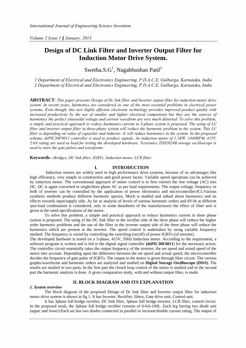
The block diagram of the proposed Design of Dc link filter and Inverter output filter for induction
motor drive system is shown in fig 1. It has Inverter, Rectifier, filters, Gate drive unit, Control unit.
It has 3phase full bridge rectifier, DC link filter, 3phase full bridge inverter, LCR filter, control circuit.
In the proposed work, the 3phase full bridge rectifier consists of 6-6A-100L. Each leg having two diode sets
(upper and lower).Each set has two diodes connected in parallel to increase/double current rating. The output of
Design of dc link filter and inverter output filter for induction motor drive system.
the rectifier is filtered by DC link filter of 1000µF inductor and two 450V capacitors. A DC link filter is
required to smooth out the ripple on the DC bus in order to run the inverter bridge.
The 3phase full bridge inverter has 6-FGA25N120ANTD-IGBT’s switches. The inverter is followed by
Gate drive unit and a control unit. The primary function of the gate drive circuit is to convert logic level control
signals into the appropriate voltage and current for efficient, reliable, switching of the IGBT module. In this
work an opto-coupler TLP250 is used to isolate the gate drive circuit and the IGBT based inverter circuit. The
opto-coupler consists of an infrared light-emitting Diode and a silicon phototransistor. The input signal is
applied to the IRLED and the output is taken from the phototransistor.
After the inverter section there is another LCR filter being placed so that the remaining harmonics at
the inverter side can also be reduce and the approximate sinusoidal waveform can be obtained at the output.The
output of 3phase full bridge rectifier with DC link filter, 3phase full bridge inverter is applied to the three phase
induction motor. A digital signal controller (dsPIC30F4011) is used to implement the core of the control
function, which simplifies the hardware setup.
Fig1. Block diagram of the proposed system
2. Power circuit design
The power circuit designed contains full bridge rectifier with DC Link filter, full bridge inverter
assembly and LCR filter assembly. At the start of the motor it experiences a very high current and the motor
may not run at the rated speed. An electromagnetic relay is used in the proposed scheme. Starting current of the
induction motor is six times that of the rated current for a duration of 4 Seconds. To limit this heavy current
flow, two wire wound resistances of 50Ω, 10W each are connected in parallel to the input supply. A single pole
change over relay is used to insert these wire wound resistors for a period of 4secs and then the relay bypasses
these resistors for the rest of the operation.
Three phase 415V, 50Hz AC supply is applied to the full bridge rectifier via starter assembly. This full
bridge rectifier converts three phase AC input into DC which is then passed to the DC link filter by two
electrolytic capacitors and an inductor. The pure DC supply is applied to the full bridge inverter which is made
up of six IGBT switches. This DC output is been given as input to another filter unit. The 3-phase induction
motor is connected to full bridge rectifier with DC link filter, full bridge inverter, RCL filter and control circuit.
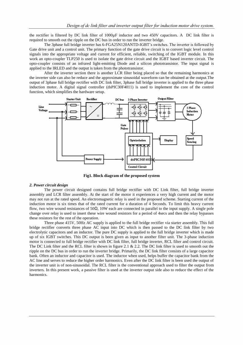
The DC Link filter and the RCL filter is shown in figure 2.1 & 2.2. The DC link filter is used to smooth out the
ripple on the DC bus in order to run the inverter bridge. Primarily, the DC link filter consists of a large capacitor
bank. Often an inductor and capacitor is used. The inductor when used, helps buffer the capacitor bank from the
AC line and serves to reduce the higher order harmonics. Even after the DC link filter is been used the output of
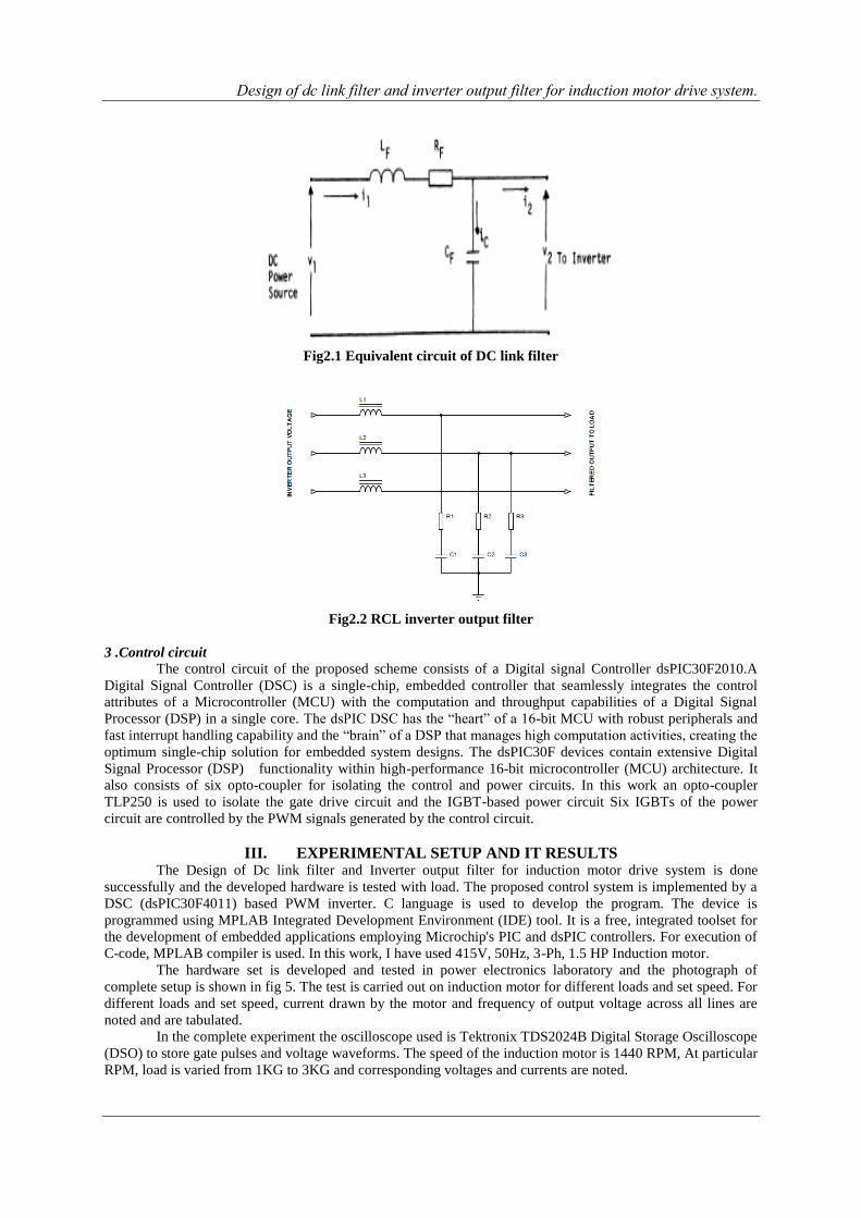
the inverter unit is of non-sinusoidal. The RCL filter is the conventional approach used to filter the output from
inverters. In this present work, a passive filter is used at the inverter output side also to reduce the effect of the
harmonics.
Design of dc link filter and inverter output filter for induction motor drive system.
Fig2.1 Equivalent circuit of DC link filter
Fig2.2 RCL inverter output filter
3 .Control circuit
The control circuit of the proposed scheme consists of a Digital signal Controller dsPIC30F2010.A
Digital Signal Controller (DSC) is a single-chip, embedded controller that seamlessly integrates the control
attributes of a Microcontroller (MCU) with the computation and throughput capabilities of a Digital Signal
Processor (DSP) in a single core. The dsPIC DSC has the “heart” of a 16-bit MCU with robust peripherals and
fast interrupt handling capability and the “brain” of a DSP that manages high computation activities, creating the
optimum single-chip solution for embedded system designs. The dsPIC30F devices contain extensive Digital
Signal Processor (DSP) functionality within high-performance 16-bit microcontroller (MCU) architecture. It
also consists of six opto-coupler for isolating the control and power circuits. In this work an opto-coupler
TLP250 is used to isolate the gate drive circuit and the IGBT-based power circuit Six IGBTs of the power
circuit are controlled by the PWM signals generated by the control circuit.
III. EXPERIMENTAL SETUP AND IT RESULTS The Design of Dc link filter and Inverter output filter for induction motor drive system is done
successfully and the developed hardware is tested with load. The proposed control system is implemented by a
DSC (dsPIC30F4011) based PWM inverter. C language is used to develop the program. The device is
programmed using MPLAB Integrated Development Environment (IDE) tool. It is a free, integrated toolset for
the development of embedded applications employing Microchip's PIC and dsPIC controllers. For execution of
C-code, MPLAB compiler is used. In this work, I have used 415V, 50Hz, 3-Ph, 1.5 HP Induction motor.
The hardware set is developed and tested in power electronics laboratory and the photograph of
complete setup is shown in fig 5. The test is carried out on induction motor for different loads and set speed. For
different loads and set speed, current drawn by the motor and frequency of output voltage across all lines are
noted and are tabulated.
In the complete experiment the oscilloscope used is Tektronix TDS2024B Digital Storage Oscilloscope
(DSO) to store gate pulses and voltage waveforms. The speed of the induction motor is 1440 RPM, At particular
RPM, load is varied from 1KG to 3KG and corresponding voltages and currents are noted.
Design of dc link filter and inverter output filter for induction motor drive system.
A. Experimental results analysisof speed control
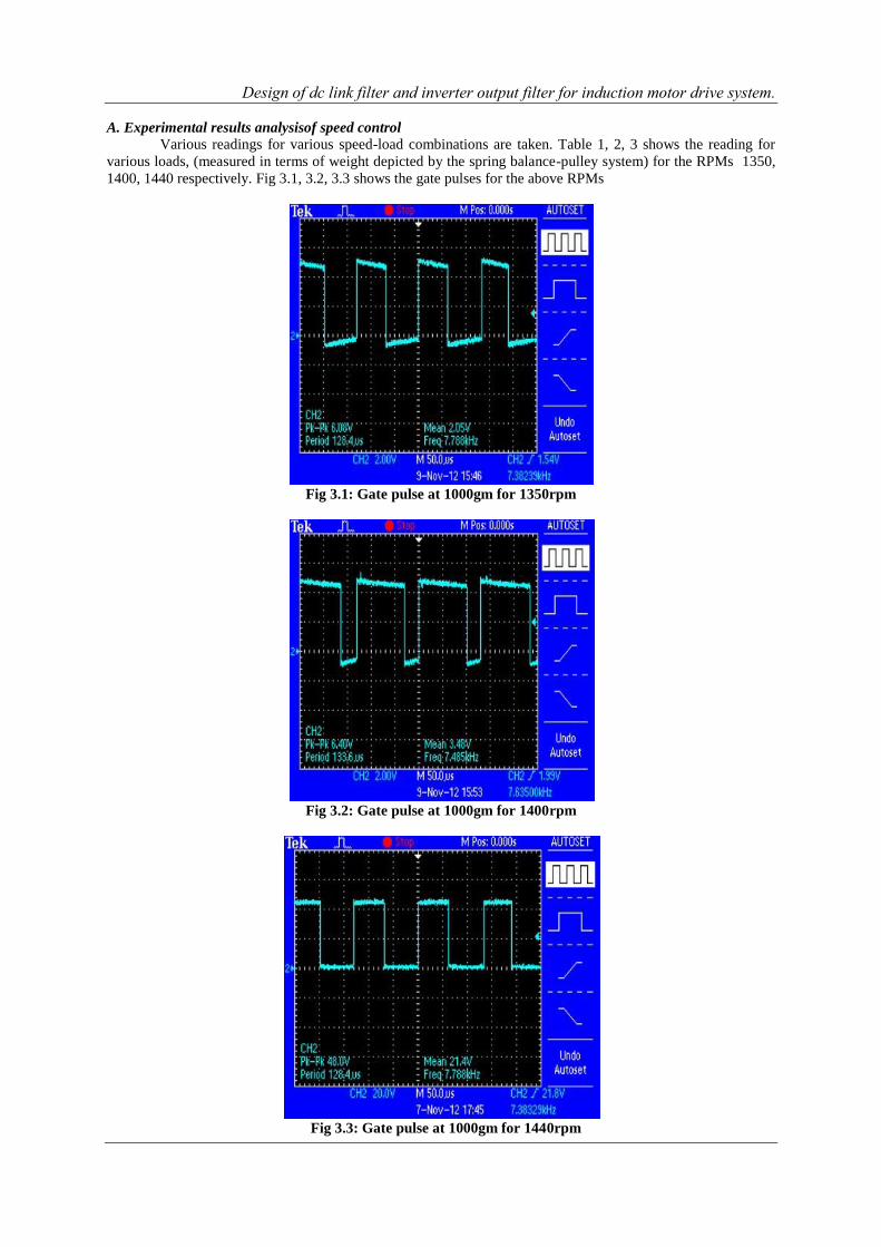
Various readings for various speed-load combinations are taken. Table 1, 2, 3 shows the reading for
various loads, (measured in terms of weight depicted by the spring balance-pulley system) for the RPMs 1350,
1400, 1440 respectively. Fig 3.1, 3.2, 3.3 shows the gate pulses for the above RPMs
Fig 3.1: Gate pulse at 1000gm for 1350rpm
Fig 3.2: Gate pulse at 1000gm for 1400rpm
Fig 3.3: Gate pulse at 1000gm for 1440rpm
Design of dc link filter and inverter output filter for induction motor drive system.
Table 1 Results for load v/s speed as 1350rpm
Table 2 Results for load v/s speed as 1400rpm
Table 3: Results for load v/s speed as 1440rpm
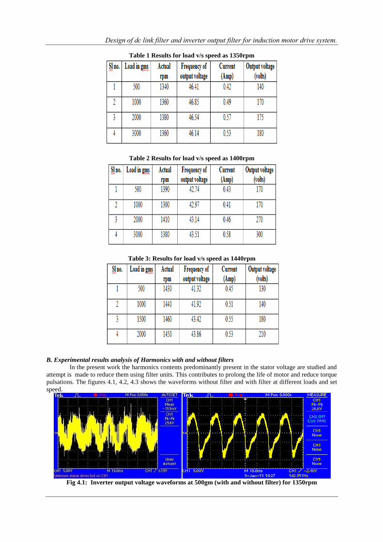
B. Experimental results analysis of Harmonics with and without filters
In the present work the harmonics contents predominantly present in the stator voltage are studied and
attempt is made to reduce them using filter units. This contributes to prolong the life of motor and reduce torque
pulsations. The figures 4.1, 4.2, 4.3 shows the waveforms without filter and with filter at different loads and set
speed.
Fig 4.1: Inverter output voltage waveforms at 500gm (with and without filter) for 1350rpm
Design of dc link filter and inverter output filter for induction motor drive system.
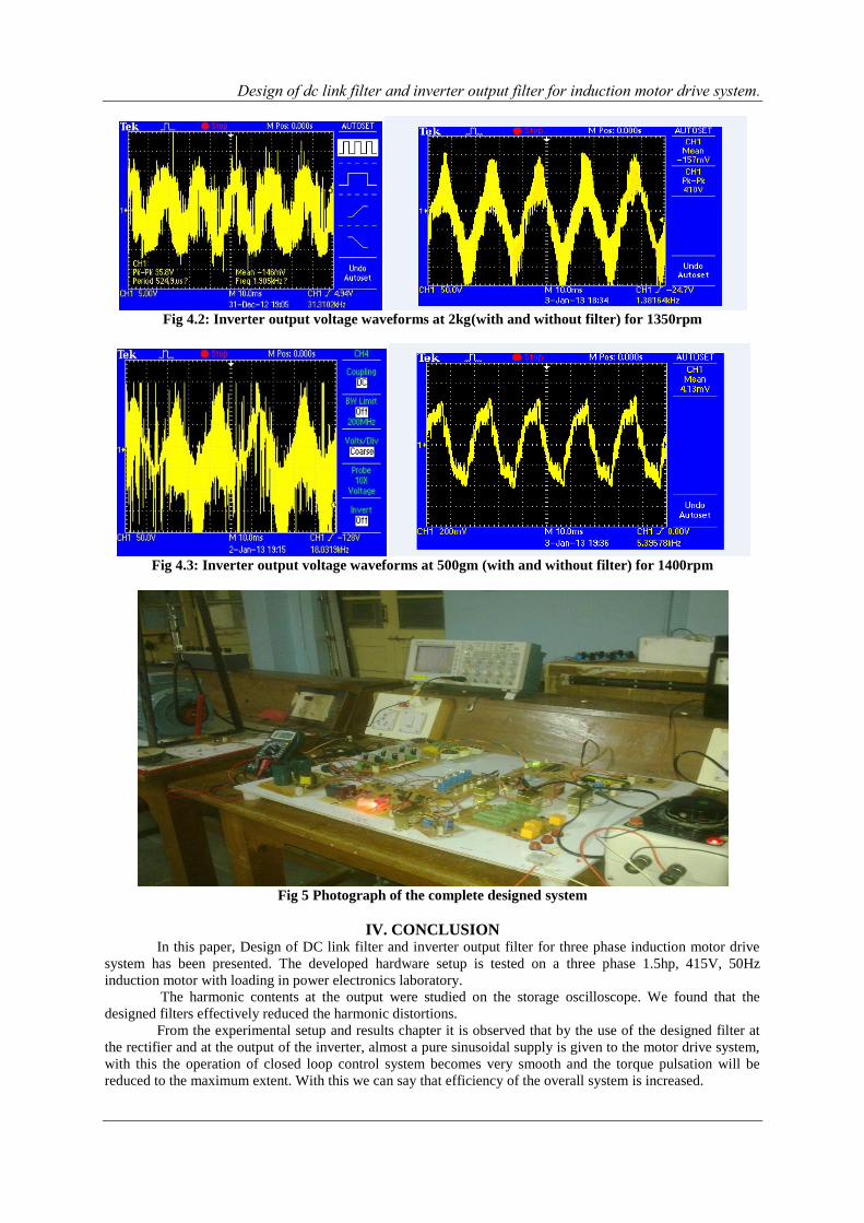
Fig 4.2: Inverter output voltage waveforms at 2kg(with and without filter) for 1350rpm
Fig 4.3: Inverter output voltage waveforms at 500gm (with and without filter) for 1400rpm
Fig 5 Photograph of the complete designed system
IV. CONCLUSION In this paper, Design of DC link filter and inverter output filter for three phase induction motor drive
system has been presented. The developed hardware setup is tested on a three phase 1.5hp, 415V, 50Hz
induction motor with loading in power electronics laboratory.
The harmonic contents at the output were studied on the storage oscilloscope. We found that the
designed filters effectively reduced the harmonic distortions.
From the experimental setup and results chapter it is observed that by the use of the designed filter at
the rectifier and at the output of the inverter, almost a pure sinusoidal supply is given to the motor drive system,
with this the operation of closed loop control system becomes very smooth and the torque pulsation will be
reduced to the maximum extent. With this we can say that efficiency of the overall system is increased.

Design of dc link filter and inverter output filter for induction motor drive system.
Advantages of the Design of DC link filter and inverter output filter for three phase induction motor drive
system are:
Reduction in harmonics, improved life of the motor, high efficiency, high power factor.
There are various application areas for harmonic filters, the most important being: Adjustable speed drives,
Computer Equipments, Welders and Battery charges.
APPENDIX The following defines the nomenclature and system parameters used in this paper :
A. Molar parameters and nomenclature: 50Hz, 415V, 1.5hp, 3-phase, 4-pole induction machine.
B. Inverter parameters : Vin : lnput voltage 415V
CT1, CT2 : DC bus capacitors 1000µf , 450V each
Q1,Q2, Q3, Q4, Q5, Q6: IGBTs FGA25N120ANTD 1200V, 25A
REFERENCES [1]. K.S.Rajashekara collectively published a paper titled “DC Link Filter Design Considerations in Three-Phase Voltage Source
Inverter-Fed Induction Motor Drive System” In IEEE transactions on industrial electronics, vol. 51,no. 3, june 2004
[2]. Najwa Mahamad Collectively published a paper titled “Application of LC Filter in Harmonics Reduction” National Power &
Energy Conference (PECoo) 2004 Proceedings, Kuala Lumpur, Malaysia. [3]. A manual from Rockwell Automation Mequon,WI “Straight Talk about PMW AC Drive Harmonic Problems and solutions”.
BOOKS: [1]. Rashid M.H, “Power Electronics-Circuits, Devices and Applications”, third edition Printice HallIndia,2001.
[2]. Bimal K.Bose, 2002, “Modern Power Electronics and AC Drives”, Prentice-Hall India.


![DHL Just Sell Redesign Wireframes v0 - kleinrogge.co.uk file[Link] [Link] [Link] [Link] [Link] [Link] [Link] [Link] [Link] [Link] [Link] [Link] [Link] [Link] [Link] [Link] [Link] [Link]](https://img.pdfslide.us/doc/110x75/5e01cdbb8c84236e132280ba/dhl-just-sell-redesign-wireframes-v0-link-link-link-link-link-link.jpg)