Embed Size (px)
Citation preview

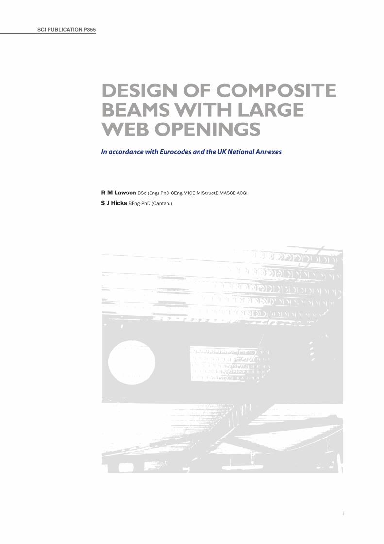
Design of Composite Beams with Large weB openings
Sponsored by:


Design of Composite Beams with Large weB openings

i
R M Lawson BSc (Eng) PhD CEng MICE MIStructE MASCE ACGI
S J Hicks BEng PhD (Cantab.)
Design of Composite Beams with Large weB openingsIn accordance with Eurocodes and the UK National Annexes
SCI PUBLICATION P355

ii
© 2011 SCI. All rights reserved.
Publication Number: SCI P355
ISBN 978-1-85942-197-0
Published by:SCI, Silwood Park, Ascot, Berkshire. SL5 7QN UK
T: +44 (0)1344 636525 F: +44 (0)1344 636570E: [email protected]
www.steel-sci.com
To report any errors, contact: [email protected]
SCI (The Steel Construction Institute) is the leading, independent provider of technical expertise and disseminator of best practice to the steel construction sector. We work in partnership with clients, members and industry peers to help build businesses and provide competitive advantage through the commercial application of our knowledge. We are committed to offering and promoting sustainable and environmentally responsible solutions.
Our service spans the following five areas:Technical information
▪ Courses ▪ Publications ▪ Online reference tools ▪ Education ▪ Codes and standards
Communications technology ▪ Websites ▪ Communities ▪ Design tools
Construction solutions ▪ Sustainability ▪ Product development ▪ Research ▪ Engineering solutions
Assessment ▪ SCI assessed
Membership ▪ Individual and corporate membership
Apart from any fair dealing for the purposes of research or private study or criticism or review, as permitted under the Copyright Designs and Patents Act, 1988, this publication may not be reproduced, stored or transmitted, in any form or by any means, without the prior permission in writing of the publishers, or in the case of reprographic reproduction only in accordance with the terms of the licences issued by the UK Copyright Licensing Agency, or in accordance with the terms of licences issued by the appropriate Reproduction Rights Organisation outside the UK.Enquiries concerning reproduction outside the terms stated here should be sent to the publishers, SCI.
Although care has been taken to ensure, to the best of our knowledge, that all data and information contained herein are accurate to the extent that they relate to either matters of fact or accepted practice or matters of opinion at the time of publication, SCI, the authors and the reviewers assume no responsibility for any errors in or misinterpretations of such data and/or information or any loss or damage arising from or related to their use.
Publications supplied to the members of the Institute at a discount are not for resale by them.
British Library Cataloguing-in-Publication Data. A catalogue record for this book is available from the British Library.
The text paper in this publication is totally chlorine free. The paper manufacturer and the printers have been independently certified in accordance with the rules of the Forest Stewardship Council.

iii
The use of composite beams with large rectangular or circular openings is a practical solution when it is required to pass service ducts through the structural zone of the beams. However, the presence of large openings in the web raises additional design considerations. Design guidance was given in an earlier SCI publication, Design for openings in webs of composite beams (P068) and design issues were further explored within a European Coal and Steel Community project, Large web openings for service integration in composite floors (ECSC project reference 7210-PR-315) and a Research Fund for Coal and Steel valorisation project (RFCS Project RFS-C2-05037).
The present publication has been written by Prof. R M Lawson of the SCI and Professor of Construction Systems at the University of Surrey, and Dr S J Hicks of HERA, New Zealand (formerly of SCI), with additional contributions from Dr W I Simms and Dr S Bake of SCI. It presents a generalised design method in accordance with the Eurocodes that may be applied to beams with discrete and closely-spaced openings.
This publication supersedes the design guidance given in publication P068.
The research and the preparation of this publication were part-funded by Tata Steel.
foreworD

iv
v
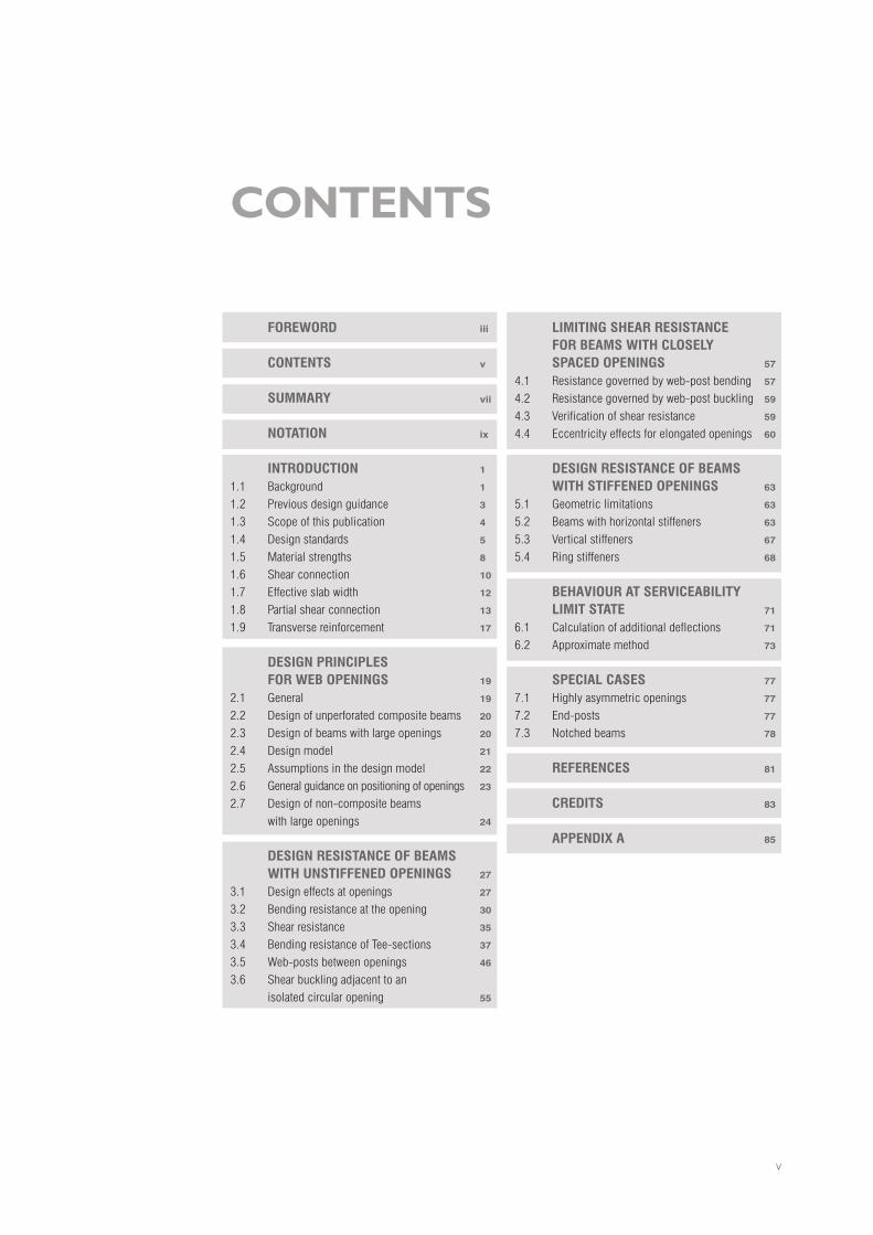
Contents
Foreword iii
Contents v
summary vii
notation ix
introduCtion 1
1.1 Background 1
1.2 Previousdesignguidance 3
1.3 Scopeofthispublication 4
1.4 Designstandards 5
1.5 Materialstrengths 8
1.6 Shearconnection 10
1.7 Effectiveslabwidth 12
1.8 Partialshearconnection 13
1.9 Transversereinforcement 17
desiGnPrinCiPLesForweBoPeninGs 19
2.1 General 19
2.2 Designofunperforatedcompositebeams 20
2.3 Designofbeamswithlargeopenings 20
2.4 Designmodel 21
2.5 Assumptionsinthedesignmodel 22
2.6 Generalguidanceonpositioningofopenings 23
2.7 Designofnon-compositebeamswithlargeopenings 24
desiGnresistanCeoFBeamswitHunstiFFenedoPeninGs 27
3.1 Designeffectsatopenings 27
3.2 Bendingresistanceattheopening 30
3.3 Shearresistance 35
3.4 BendingresistanceofTee-sections 37
3.5 Web-postsbetweenopenings 46
3.6 Shearbucklingadjacenttoanisolatedcircularopening 55
LimitinGsHearresistanCeForBeamswitHCLoseLysPaCedoPeninGs 57
4.1 Resistancegovernedbyweb-postbending 57
4.2 Resistancegovernedbyweb-postbuckling 59
4.3 Verificationofshearresistance 59
4.4 Eccentricityeffectsforelongatedopenings 60
desiGnresistanCeoFBeamswitHstiFFenedoPeninGs 63
5.1 Geometriclimitations 63
5.2 Beamswithhorizontalstiffeners 63
5.3 Verticalstiffeners 67
5.4 Ringstiffeners 68
BeHaViouratserViCeaBiLityLimitstate 71
6.1 Calculationofadditionaldeflections 71
6.2 Approximatemethod 73
sPeCiaLCases 77
7.1 Highlyasymmetricopenings 77
7.2 End-posts 77
7.3 Notchedbeams 78
reFerenCes 81
Credits 83
aPPendiXa 85

vi
vii
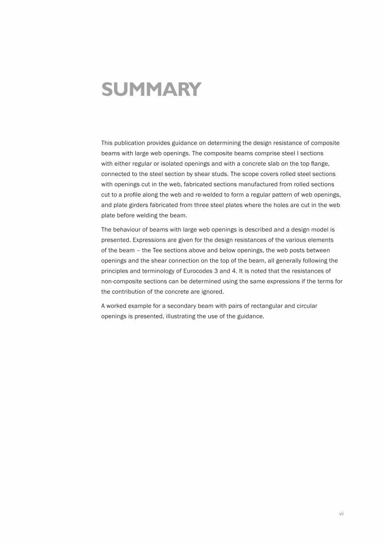
summary
This publication provides guidance on determining the design resistance of composite beams with large web openings. The composite beams comprise steel I sections with either regular or isolated openings and with a concrete slab on the top flange, connected to the steel section by shear studs. The scope covers rolled steel sections with openings cut in the web, fabricated sections manufactured from rolled sections cut to a profile along the web and re-welded to form a regular pattern of web openings, and plate girders fabricated from three steel plates where the holes are cut in the web plate before welding the beam.
The behaviour of beams with large web openings is described and a design model is presented. Expressions are given for the design resistances of the various elements of the beam – the Tee sections above and below openings, the web posts between openings and the shear connection on the top of the beam, all generally following the principles and terminology of Eurocodes 3 and 4. It is noted that the resistances of non-composite sections can be determined using the same expressions if the terms for the contribution of the concrete are ignored.
A worked example for a secondary beam with pairs of rectangular and circular openings is presented, illustrating the use of the guidance.

viii

ix
The notation follows that of the Eurocodes, where possible.
cross-sectional area of bottom Teecross-sectional area of top Teecross-sectional area of concretecross-sectional area of flange cross-sectional area of horizontal stiffener(s)cross-sectional area of tensile reinforcementshear area of beamshear area of bottom Teeshear area of top Teecross-sectional area of web of the bottom Teecross-sectional area of web of a Teebeam spacingeffective slab width at any position along the spaneffective slab width at an openingflange widthaverage width of decking rib (minimum width for re-entrant decking); distance between centres of outstand shear connectors in a groupoutstand width of stiffenereffective width of slab for vertical shear resistancediameter of shank of a stud shear connector; effective depth of concrete resisting vertical sheareccentricity of centre of opening above the centreline of the weboffset distance of centre of stiffener from horizontal edge of openingmodulus of elasticity of steel
notation
secant modulus of elasticity of concretedesign value of concrete compressive strength characteristic compressive cylinder strength of concretecharacteristic compressive cube strength of concreteultimate tensile strength of steelyield strength of steelyield strength of steel in stiffenersdesign axial force in a stiffener (for verifying end anchorage)design axial resistance of a stiffenertensile force acting on shear connector at the end of an opening when the Vierendeel bending resistance of a composite Tee is fully mobilizedpermanent actiondepth of steel beamdepth of bottom Teedepth of top Teedepth of concrete above decking profile (= hs - hd)overall depth of decking profileeffective depth of steel section between centroids of the Teesdepth of openingdepth of decking profile (measured to its shoulder)total depth of slab effective depth of slab for punching shearnominal height of shear connector (typically either 100 mm or 125 mm)
AbT
A tT
Ac
A f
A r
Asl
Av
Av,bT
Av,tT
Aw,b
Aw,T
b beff
beff,o
bf
b0
br
bw
d
eo
er
E
Ecm
fcd
fck
fck,cube
fu
fy
fyr
Fr,d
Fr,Rd
Ften
G h
hb
h t
hc
hd
heff
ho
hp
hs
hs,eff
hsc
x
NOTATION
clear web depth of beam between flangesdepth of web of bottom Teedepth of web of top Teedepth of web of Tee (hwt or hwb, as appropriate)second moment of area about y-y (major) axissecond moment of area of composite section at an opening about y-y (major) axisreduction factor on Vierendeel bending resistance of Tee due to the flexibility of a long openingreduction factor for resistance of a headed stud used with profiled sheeting transverse to the beamupper limit to the value of kt effective length of rectangular opening(clear) length of openingeffective length of opening used in assessing the section class of a Tee in Vierendeel bendinganchorage length of a horizontal stiffener to a rectangular opening (beyond the end of the opening) buckling length of web-postlength; spanequivalent spanplastic bending resistance of steel sectionbending resistance of the bottom Tee, reduced for axial tension and shearelastic bending resistance (of Tee)design bending momentplastic bending resistance (of Tee section) reduced for axial force design bending moment at the centreline of an openingbending resistance of the composite section at the centreline of an openingplastic bending resistance (of Tee section)bending resistance of the top Tee, reduced for axial tension and sheardesign bending moment in web-post at mid-height of openings
(elastic) bending resistance of a web-posttensile force acting in bottom Teetensile resistance of the steel beamdesign value of the compression force in the concrete flange design value of the compression force in the concrete flange corres-ponding to full shear connectioncompression resistance of the concrete slab over its effective slab width (either limited by concrete compressive resistance or by shear connection provided)is the concrete compressive resistance over the effective width of the slabaxial resistance of bottom Teeaxial resistance of top Teeeffective compression force in web-postbuckling resistance of web-postincrease in tension force in the bottom Tee between the centrelines of adjacent openingsincrease in compression resistance of the slab, due to the shear connection over an openingincrease in compression resistance of the slab, due to the shear connection between the centrelines of the openingsmodular ratio; number of shear connectorsnumber of shear connectors required for full shear connectionnumber of shear connectors per rib of transverse deckingnumber of shear connectors from the support to the centreline of an openingnumber of shear connectors placed directly over an openingnumber of shear connectors placed in the slab between centrelines of adjacent openingsdesign shear force on a shear connector
hwb
hwt
hw,T
Iy
Iy,o
ko
kt
kt,max
�e
�o
�o,eff
�v
�w
LLe
Mpl,a,Rd
MbT,NV,Rd
M el,Rd
MEd
Mpl,N,Rd
Mo,Ed
Mo,Rd
Mpl,Rd
MtT,NV,Rd
Mwp,Ed
Mwp,Rd
NbT,Ed
Na,Rd
Nc,Ed
Nc,f
Nc,Rd
Nc,s,Rd
NbT,Rd
N tT,Rd
Nwp,Ed
Nwp,Rd
Nb,Ed ∆
Nco,Rd∆
Ncs,Rd∆
n
nf
nr
nsc,o
nsc,s
PEd
nsc
hw
xi
design shear resistance of shear connector; design shear resistance of shear connector, reduced for transverse deckingvariable action, load per unit lengthvariable action (point load or total load)root radius of rolled steel sectioncorner radius of openingcentre-to-centre spacing of adjacent openingswidth of end-postedge-to-edge spacing of adjacent openingsflange thicknessthickness of stiffenerweb thicknesseffective web thickness (of Tee) reduced due for shearshear strength of concrete slab at an openingshear force in bottom Teeshear resistance of bottom Teeshear resistance of concrete slab at an openingdesign shear forcevertical shear resistance of beam at an openingshear resistance of top Teelongitudinal shear resistance of web-post between openingslongitudinal shear force in web-post between openingsdistance of opening from nearer supportdeflection of unperforated beam (subscript b for bending, sw for self weight)additional deflection due to openings (subscript b for bending and v for shear)depth of concrete in compressiondepth of centroid of Tee from outer face of flangedepth of plastic neutral axis of Tee from outer face of flange
Axeslongitudinal axis along the membermajor axis (parallel to flanges)minor axis (parallel to web)
Greek Symbolsreduction factor on shear connector resistance due to h /sc d ratiopartial factor for resistance of steel cross sectionspartial factor for resistance of steel members to instabilitypartial factor for concretepartial factor for shear resistance of a headed studdegree of shear connectionutilization factorcompressive stress in concrete from axial loadnon-dimensional slenderness of web for web-post bucklingslenderness value to determine the relative slenderness
235 fy , where fy is in N/mm2
factor for a combination value of i-th variable actionreduction factor for unfavourable permanent actions
q Q
rro
s
se
so
tf
tr
tw
tw,eff
vc,Rd
Vb
Vb,Rd
Vc,Rd
VEd
VRd
V t,Rd
Vwp,Rd
Vwp,Ed
x
w
wadd
zc
zel
z pl
xy-yz-z
α
M0 γ
M1 γ
C γVγ
η
µcpσ
λ
1λ
εi0,ψ
ξ
PRd

xiixii
1
1.1 Background
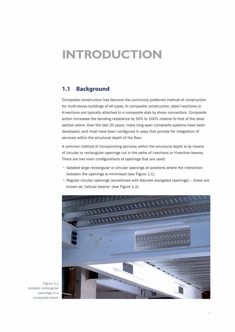
Composite construction has become the commonly preferred method of construction for multi-storey buildings of all types. In composite construction, steel I-sections or H-sections are typically attached to a composite slab by shear connectors. Composite action increases the bending resistance by 50% to 100% relative to that of the steel section alone. Over the last 20 years, many long span composite systems have been developed, and most have been configured in ways that provide for integration of services within the structural depth of the floor.
A common method of incorporating services within the structural depth is by means of circular or rectangular openings cut in the webs of I-sections or H-section beams. There are two main configurations of openings that are used:
▪ Isolated large rectangular or circular openings at positions where the interaction between the openings is minimised (see Figure 1.1).
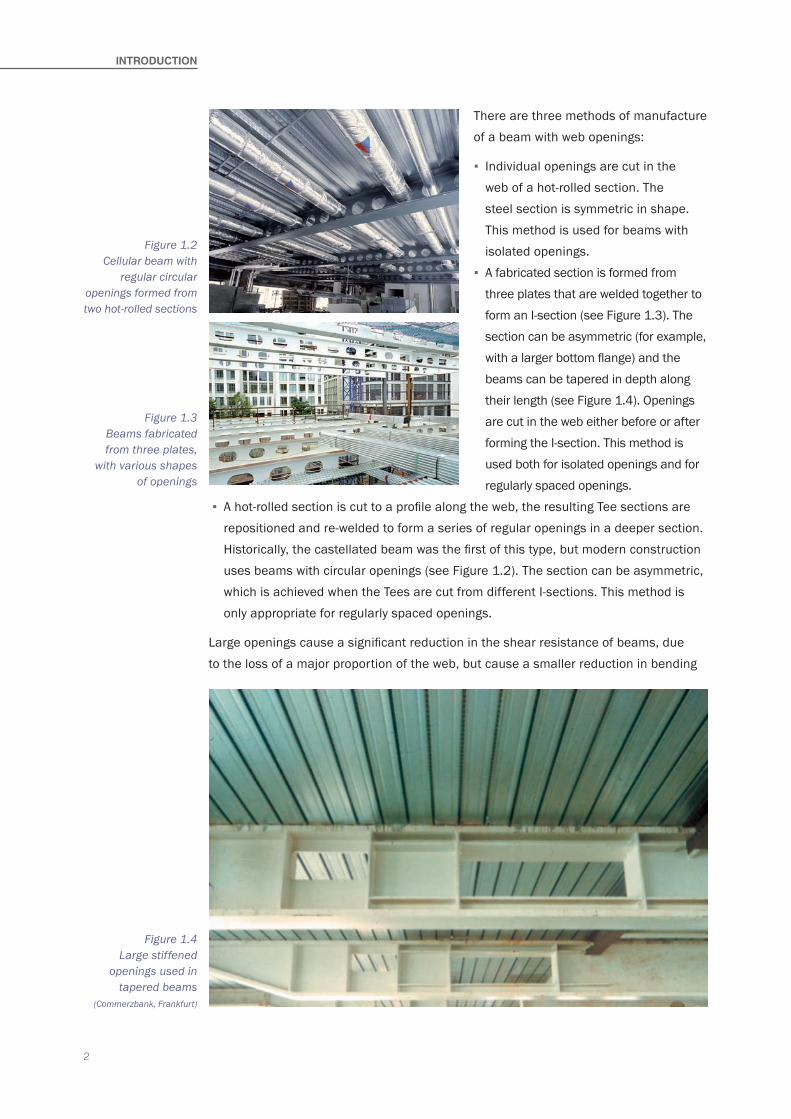
▪ Regular circular openings (sometimes with discrete elongated openings) – these are known as ‘cellular beams’ (see Figure 1.2).
introDuCtion
Figure 1.1 Isolated rectangular
openings in a composite beam
2
INTrOdUCTION
There are three methods of manufacture of a beam with web openings:
▪ Individual openings are cut in the web of a hot-rolled section. The steel section is symmetric in shape. This method is used for beams with isolated openings.
▪ A fabricated section is formed from three plates that are welded together to form an I-section (see Figure 1.3). The section can be asymmetric (for example, with a larger bottom flange) and the beams can be tapered in depth along their length (see Figure 1.4). Openings are cut in the web either before or after forming the I-section. This method is used both for isolated openings and for regularly spaced openings.
▪ A hot-rolled section is cut to a profile along the web, the resulting Tee sections are repositioned and re-welded to form a series of regular openings in a deeper section. Historically, the castellated beam was the first of this type, but modern construction uses beams with circular openings (see Figure 1.2). The section can be asymmetric, which is achieved when the Tees are cut from different I-sections. This method is only appropriate for regularly spaced openings.
Large openings cause a significant reduction in the shear resistance of beams, due to the loss of a major proportion of the web, but cause a smaller reduction in bending
Figure 1.2 Cellular beam with
regular circular openings formed from two hot-rolled sections
Figure 1.3 Beams fabricated from three plates,
with various shapes of openings
Figure 1.4 Large stiffened
openings used in tapered beams
(Commerzbank, Frankfurt)
3
resistance. The shear transfer across sections with large openings is an important design consideration, and it is good practice to locate large openings remote from the high shear zones of a beam in order to minimise their effect.
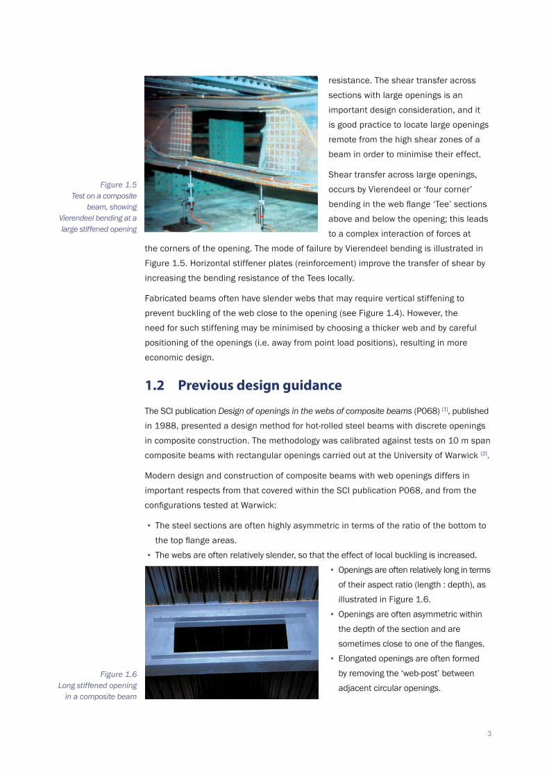
Shear transfer across large openings, occurs by Vierendeel or ‘four corner’ bending in the web flange ‘Tee’ sections above and below the opening; this leads to a complex interaction of forces at
the corners of the opening. The mode of failure by Vierendeel bending is illustrated in Figure 1.5. Horizontal stiffener plates (reinforcement) improve the transfer of shear by increasing the bending resistance of the Tees locally.
Fabricated beams often have slender webs that may require vertical stiffening to prevent buckling of the web close to the opening (see Figure 1.4). However, the need for such stiffening may be minimised by choosing a thicker web and by careful positioning of the openings (i.e. away from point load positions), resulting in more economic design.
1.2 Previous design guidance
The SCI publication Design of openings in the webs of composite beams (P068) [1], published in 1988, presented a design method for hot-rolled steel beams with discrete openings in composite construction. The methodology was calibrated against tests on 10 m span composite beams with rectangular openings carried out at the University of Warwick [2].
Modern design and construction of composite beams with web openings differs in important respects from that covered within the SCI publication P068, and from the configurations tested at Warwick:
▪ The steel sections are often highly asymmetric in terms of the ratio of the bottom to the top flange areas.
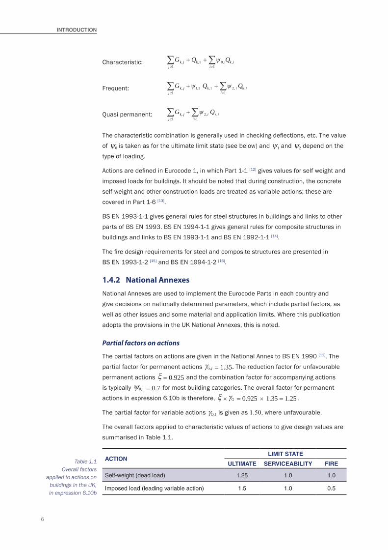
▪ The webs are often relatively slender, so that the effect of local buckling is increased. ▪ Openings are often relatively long in terms
of their aspect ratio (length : depth), as illustrated in Figure 1.6.
▪ Openings are often asymmetric within the depth of the section and are sometimes close to one of the flanges.
▪ Elongated openings are often formed by removing the ‘web-post’ between adjacent circular openings.
Figure 1.5 Test on a composite
beam, showing Vierendeel bending at a large stiffened opening
Figure 1.6 Long stiffened opening
in a composite beam
4
INTrOdUCTION
These changes in practice have necessitated a re-appraisal of P068, so that guidance can be extended to cover a wider range of applications for both hot-rolled and fabricated steel sections. However, it is not possible to give definitive guidance for all cases and general structural design principles should still be observed. This is particularly true for fabricated sections.
Furthermore, the introduction of Eurocodes requires that design methods are consistent with the principles and application rules of Eurocode 3 and Eurocode 4, for steel and composite construction respectively. A draft amendment to Annex N of the pre-standard ENV 1993-1-1: 1992/A2: 1998 [3] covering the design of beams with holes in the web was started but the committee draft was not published, nor incorporated into the published Eurocode. Other international guidance on beams with large web openings exists in the USA [4], but this does not apply to cellular beams or to beams with closely spaced openings.
General guidance on structure-services integration may be found in Design of steel framed buildings for service integration (P166) [5]. It presents layouts of ducts and terminal units for Fan-Coil and VAV air-conditioning systems in various forms of long span steel construction.
1.3 Scope of this publication
This publication extends the guidance in SCI P068 (which is now withdrawn) for both hot-rolled and fabricated sections and follows the principles and relevant application rules of BS EN 1993-1-1 [6] and BS EN 1994-1-1 [7]. The scope of the present publication covers the design of simply-supported composite beams for the following cases:
▪ Beams fabricated from hot-rolled sections and from plates. ▪ Symmetric and asymmetric steel sections (in which the ratio of the bottom to top flange areas is less than 3 to 1).
▪ Steel sections with Class 1, 2 or 3 flanges and Class 1, 2, 3 or 4 webs. ▪ Openings placed centrally and non-centrally in the depth of the section. ▪ Rectangular openings, circular openings and elongated circular openings. ▪ Beams with widely-spaced openings and with closely spaced openings. ▪ Cellular beams with uniform web thickness. ▪ Notched beams.
The publication does not directly cover:
▪ Web-post buckling effects in cellular beams with different web thicknesses in the top and bottom of the web.
▪ Continuous beams. ▪ Tapered beams. ▪ Curved beams. ▪ Slim floor beams designed with composite action. ▪ Fire engineering design.
5
The guidance may be applied to non-composite beams by ignoring the structural effect of the concrete slab. (This application also covers the construction stage for composite beams, before the concrete has hardened.) Where additional considerations apply to non-composite beams, this is noted.
References to Eurocodes in this publication are to the versions published by BSI and include reference to the UK National Annexes, where appropriate.
1.4 Design standards
This publication is prepared in general structural engineering terms and refers to rules in BS EN 1993-1-1 and BS EN 1994-1-1, which supersede BS 5950-1 [8] and BS 5950-3 [9] respectively. As this publication deals with a common design case that is not covered by these Eurocodes, the publication may be considered to provide non-contradictory complimentary information (NCCI).
1.4.1 Eurocodes
The basis of structural design in the Eurocodes is presented in the ‘core’ document, BS EN 1990 [11], which also defines the combinations of actions (loads). For the design of beams in braced frames at the ultimate limit state, the most commonly applicable combination of actions for buildings in the UK* is given by expression 6.10b:
ξ γ γ γ ψj G, k, Q,1 k,1 Q, 0, k,j j i i iij
G Q Q+ +>≥∑∑
11
where:
Gk, j is the characteristic value of the j th permanent action
Qk,1 is the characteristic value of the leading variable action
Qk,i is the characteristic value of the i th variable action
G, jγ is the partial factor for the j th permanent action
Q,1γ is the partial factor for the leading variable action
Q,iγ is the partial factor for the i th variable action
i0,ψ is the combination factor for other actions
ξ is the reduction factor for unfavourable permanent actions.
At the serviceability limit state, the characteristic combination of actions should be used when considering irreversible deformations. The frequent combination applies to cases which occur regularly and the quasi-permanent condition applies to issues such as creep or shrinkage deflections. The combinations of actions for these conditions are defined by the following expressions:
Note: * The expression which gives the most onerous effects depends on the values of the nationally determined parameters. See P361 [10] for a discussion of combinations of actions according to BS EN 1990.
6
INTrOdUCTION
Characteristic: G Q Qj i iij
k, k,1 0, k,+ +>≥∑∑ ψ
11
Frequent: G Q Qj i iij
k, k,1 2, k,+ +>≥∑∑ ψ ψ1 1
11,
Quasi permanent: G Qj i iij
k, 2, k,+>≥∑∑ ψ
11
The characteristic combination is generally used in checking deflections, etc. The value of ψ0 is taken as for the ultimate limit state (see below) and ψ1 and ψ2 depend on the type of loading.
Actions are defined in Eurocode 1, in which Part 1-1 [12] gives values for self weight and imposed loads for buildings. It should be noted that during construction, the concrete self weight and other construction loads are treated as variable actions; these are covered in Part 1-6 [13].
BS EN 1993-1-1 gives general rules for steel structures in buildings and links to other parts of BS EN 1993. BS EN 1994-1-1 gives general rules for composite structures in buildings and links to BS EN 1993-1-1 and BS EN 1992-1-1 [14].
The fire design requirements for steel and composite structures are presented in BS EN 1993-1-2 [15] and BS EN 1994-1-2 [16].
1.4.2 National Annexes
National Annexes are used to implement the Eurocode Parts in each country and give decisions on nationally determined parameters, which include partial factors, as well as other issues and some material and application limits. Where this publication adopts the provisions in the UK National Annexes, this is noted.
Partial factors on actions
The partial factors on actions are given in the National Annex to BS EN 1990 [11]. The partial factor for permanent actions G,jγ = 1.35. The reduction factor for unfavourable permanent actions ξ = 0.925 and the combination factor for accompanying actions is typically 0,1ψ = 0.7 for most building categories. The overall factor for permanent actions in expression 6.10b is therefore, Gξ γ = 0.925 1.35 = 1.25× × .
The partial factor for variable actions Q,1γ is given as 1.50, where unfavourable.
The overall factors applied to characteristic values of actions to give design values are summarised in Table 1.1.
ACTIONLIMIT STATe
ULTIMATe ServICeABILITy FIre
Self-weight (dead load) 1.25 1.0 1.0
Imposed load (leading variable action) 1.5 1.0 0.5
Table 1.1 Overall factors
applied to actions on buildings in the UK, in expression 6.10b
7
Partial factors on material strengths
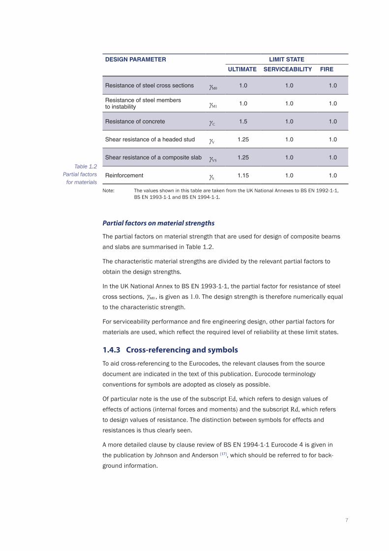
The partial factors on material strength that are used for design of composite beams and slabs are summarised in Table 1.2.
The characteristic material strengths are divided by the relevant partial factors to obtain the design strengths.
In the UK National Annex to BS EN 1993-1-1, the partial factor for resistance of steel cross sections, M0 γ , is given as 1.0. The design strength is therefore numerically equal to the characteristic strength.
For serviceability performance and fire engineering design, other partial factors for materials are used, which reflect the required level of reliability at these limit states.
1.4.3 Cross-referencing and symbols
To aid cross-referencing to the Eurocodes, the relevant clauses from the source document are indicated in the text of this publication. Eurocode terminology conventions for symbols are adopted as closely as possible.
Of particular note is the use of the subscript Ed, which refers to design values of effects of actions (internal forces and moments) and the subscript Rd, which refers to design values of resistance. The distinction between symbols for effects and resistances is thus clearly seen.
A more detailed clause by clause review of BS EN 1994-1-1 Eurocode 4 is given in the publication by Johnson and Anderson [17], which should be referred to for back-ground information.
Table 1.2 Partial factors
for materials
deSIgN PArAMeTer LIMIT STATe
ULTIMATe ServICeABILITy FIre
Resistance of steel cross sections M0 γ 1.0 1.0 1.0
Resistance of steel members to instability M1 γ 1.0 1.0 1.0
Resistance of concrete C γ 1.5 1.0 1.0
Shear resistance of a headed stud Vγ 1.25 1.0 1.0
Shear resistance of a composite slab VSγ 1.25 1.0 1.0
Reinforcement Sγ 1.15 1.0 1.0
Note: The values shown in this table are taken from the UK National Annexes to BS EN 1992-1-1, BS EN 1993-1-1 and BS EN 1994-1-1.
8
INTrOdUCTION
1.5 Material strengths
1.5.1 Steel strength
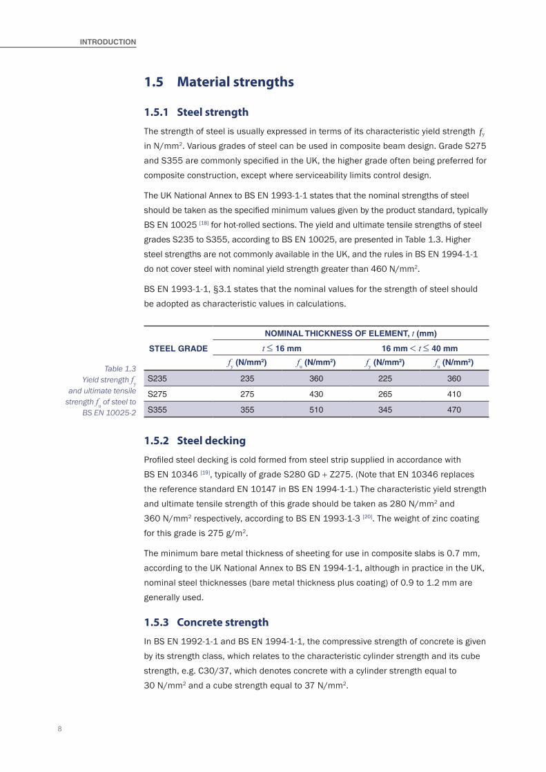
The strength of steel is usually expressed in terms of its characteristic yield strength fy in N/mm2. Various grades of steel can be used in composite beam design. Grade S275 and S355 are commonly specified in the UK, the higher grade often being preferred for composite construction, except where serviceability limits control design.
The UK National Annex to BS EN 1993-1-1 states that the nominal strengths of steel should be taken as the specified minimum values given by the product standard, typically BS EN 10025 [18] for hot-rolled sections. The yield and ultimate tensile strengths of steel grades S235 to S355, according to BS EN 10025, are presented in Table 1.3. Higher steel strengths are not commonly available in the UK, and the rules in BS EN 1994-1-1 do not cover steel with nominal yield strength greater than 460 N/mm2.
BS EN 1993-1-1, §3.1 states that the nominal values for the strength of steel should be adopted as characteristic values in calculations.
1.5.2 Steel decking
Profiled steel decking is cold formed from steel strip supplied in accordance with BS EN 10346 [19], typically of grade S280 GD + Z275. (Note that EN 10346 replaces the reference standard EN 10147 in BS EN 1994-1-1.) The characteristic yield strength and ultimate tensile strength of this grade should be taken as 280 N/mm2 and 360 N/mm2 respectively, according to BS EN 1993-1-3 [20]. The weight of zinc coating for this grade is 275 g/m2.
The minimum bare metal thickness of sheeting for use in composite slabs is 0.7 mm, according to the UK National Annex to BS EN 1994-1-1, although in practice in the UK, nominal steel thicknesses (bare metal thickness plus coating) of 0.9 to 1.2 mm are generally used.
1.5.3 Concrete strength
In BS EN 1992-1-1 and BS EN 1994-1-1, the compressive strength of concrete is given by its strength class, which relates to the characteristic cylinder strength and its cube strength, e.g. C30/37, which denotes concrete with a cylinder strength equal to 30 N/mm2 and a cube strength equal to 37 N/mm2.
STeeL grAde
NOMINAL ThICkNeSS OF eLeMeNT, t (mm)
t ≤ 16 mm 16 mm < t ≤ 40 mm
fy (N/mm2) fu (N/mm2) fy (N/mm2) fu (N/mm2)
S235 235 360 225 360
S275 275 430 265 410
S355 355 510 345 470
Table 1.3 Yield strength fy
and ultimate tensile strength fu of steel to
BS EN 10025-2
9
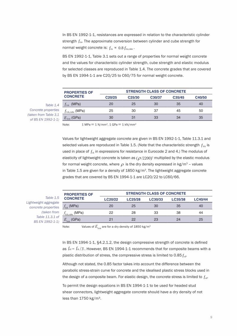
In BS EN 1992-1-1, resistances are expressed in relation to the characteristic cylinder strength fck. The approximate conversion between cylinder and cube strength for normal weight concrete is: ck ≈f ck,cubef0.8 .
BS EN 1992-1-1, Table 3.1 sets out a range of properties for normal weight concrete and the values for characteristic cylinder strength, cube strength and elastic modulus for selected classes are reproduced in Table 1.4. The concrete grades that are covered by BS EN 1994-1-1 are C20/25 to C60/75 for normal weight concrete.
Table 1.4 Concrete properties
(taken from Table 3.1 of BS EN 1992-1-1)
Table 1.5 Lightweight aggregate
concrete properties (taken from
Table 11.3.1 of BS EN 1992-1-1)
Values for lightweight aggregate concrete are given in BS EN 1992-1-1, Table 11.3.1 and selected values are reproduced in Table 1.5. (Note that the characteristic strength lckf is used in place of fck in expressions for resistance in Eurocode 2 and 4.) The modulus of elasticity of lightweight concrete is taken as ρ /2200)2( multiplied by the elastic modulus for normal weight concrete, where ρ is the dry density expressed in kg/m3 – values in Table 1.5 are given for a density of 1850 kg/m3. The lightweight aggregate concrete grades that are covered by BS EN 1994-1-1 are LC20/22 to LC60/66.
PrOPerTIeS OF CONCreTe
STreNgTh CLASS OF CONCreTe
C20/25 C25/30 C30/37 C35/45 C40/50
lckf (MPa) 20 25 30 35 40
lck,cubef (MPa) 25 30 37 45 50
lcmE (GPa) 30 31 33 34 35
Note: 1 MPa = 1 N/mm2, 1 GPa = 1 kN/mm2
PrOPerTIeS OF CONCreTe
STreNgTh CLASS OF CONCreTe
LC20/22 LC25/28 LC30/33 LC35/38 LC40/44
flck (MPa) 20 25 30 35 40
flck,cube (MPa) 22 28 33 38 44
Elcm (GPa) 21 22 23 24 25
Note: Values of Elcm are for a dry density of 1850 kg/m3
In BS EN 1994-1-1, §4.2.1.2, the design compressive strength of concrete is defined as cdf ckf cγ= / . However, BS EN 1994-1-1 recommends that for composite beams with a plastic distribution of stress, the compressive stress is limited to 0.85 fcd.
Although not stated, the 0.85 factor takes into account the difference between the parabolic stress-strain curve for concrete and the idealised plastic stress blocks used in the design of a composite beam. For elastic design, the concrete stress is limited to fcd.
To permit the design equations in BS EN 1994-1-1 to be used for headed stud shear connectors, lightweight aggregate concrete should have a dry density of not less than 1750 kg/m³.
10
INTrOdUCTION
1.6 Shear connection
1.6.1 Stud shear connectors
According to BS EN 1994-1-1, §6.6.3, the design resistance of headed shear connectors (studs) embedded in solid concrete should be determined from the smaller of:
PRd 0 8 42. /f du
V
πγ
=
and
PRd 0 29 2. α
γd f Eck cm
V
=
with
α hdsc +
1= 0.2 for 3 ≤ hsc / d ≤ 4
α for hsc / d > 4= 1
where:
d is the diameter of the shank of the stud (16 mm ≤ d ≤ 25 mm)
hsc is the nominal height of the stud
fu is the specified ultimate tensile strength of the stud material
fck is the characteristic cylinder strength of the concrete (of density not less than 1750 kg/m³)
Ecm is the secant modulus of elasticity of the concrete (see Table 1.4).
Studs are normally specified as type SD1 in accordance with EN ISO 13918, for which
fu = 450 N/mm2.
The design resistances of standard 19 mm diameter × 100 mm long (length-as-welded is typically 95 mm) shear connectors embedded in solid concrete slabs are presented in Table 1.6 and Table 1.7 (the dry density of lightweight concrete used in the UK is typically 1850 kg/m3).
deSIgN reSISTANCeS OF SheAr CONNeCTOrS (kN) FOr CONCreTe grAde
C20/25 C25/30 C30/37 C35/45 > C40/50
65 74 81 81 81
Note: Values based on the UK National Annex value for Vγ and with fu = 450 N/mm2
deSIgN reSISTANCeS OF SheAr CONNeCTOrS (kN) FOr CONCreTe grAde
LC20/22 LC25/28 LC30/33 LC35/38 LC40/45
55 62 70 77 81
Note: Values based on the UK National Annex value for Vγ and with fu = 450 N/mm2
Table 1.7 Design resistances of shear
connectors embedded in lightweight concrete (with dry
density ρ = 1850 kg/m³)
Table 1.6 Design resistances of shear
connectors embedded in normal weight concrete solid slabs

11
When composite decking is used, these values may be reduced according to an empirical formula taking account of the shape of the decking profile (see Section 1.6.2).
1.6.2 Influence of decking shape on shear connection
The efficiency of the shear connection between the composite slab and the composite beam may be reduced as a result of the shape and orientation of the decking profile and the number of shear connectors placed in each rib. The resistance of the shear connectors is highly dependent on the area of concrete around them and the embedment of the head of the shear connector into the slab topping. A simple reduction factor formula is used to take account of the decking profile shape and the number of shear connectors in a group.
Strength reduction factor in decking with ribs transverse to the beam
According to BS EN 1994-1-1, §6.6.4.2, the reduction factor kt for the resistance of shear connectors (relative to resistance in a solid slab) is given by the empirical formula:
kt 0 7 1.n
bh
hhr
0
p
sc
p
−
= but not more than kt,max
where:
b0 is the average rib width (or minimum width for re-entrant profiles)
hsc is the nominal height of the stud
hp is the profile height (to the shoulder of the profile)
nr is the number of studs per rib (nr = 1 or 2)
kt,max is the upper limit on kt (see Table 1.8).
According to BS EN 1994-1-1, §6.6.5.8(1), the nominal height of a shear connector should project at least 2 × stud diameter above the top of the decking (i.e. 38 mm for 19 mm diameter shear connectors).
The coefficient of 0.7 in the above expression has been established according to the requirements given in BS EN 1990 Annex D [11] on the basis of recent test evidence on the performance of shear connectors.
It is recognised that the formula is conservative for single shear connectors per decking rib but may be unconservative for shear connectors in pairs. Therefore, upper limits kt,max are given, as shown in Table 1.8. The upper limit is also presented as a function of the thickness of the steel sheet and whether the shear connectors are through-deck welded, as it is recognised that the decking plays a beneficial role in transferring shear into the slab. The limits to the shear connector diameters reflect the experimental data available in calibrating the expression.
Recent tests in the UK have explored the shear resistance of studs in decking that is transverse to the beam, with particular reference to the level of the mesh

12
INTrOdUCTION
reinforcement. It was concluded that in some circumstances a reduction factor should be applied to the resistance calculated in the above manner. For further guidance, see document PN001 on: www.steel-ncci.co.uk.
Strength reduction factor in off-centre placing of shear connectors
Many modern decking profiles have a central stiffening fold in the rib that requires the shear connector to be located off-centre in the rib. The preferred position of attachment is where the shear connectors are placed on the side of the rib closest to the nearest support.
The rules in BS EN 1994-1-1 are only given for centrally welded shear connectors. In cases where the studs cannot be placed centrally, it is advised that shear connectors are welded in a ‘favourable location’ (where the zone of concrete in compression in front of the stud is larger than that behind the stud) or one either side of the central position.
Strength reduction factor in decking parallel to beam
For the case where the decking is orientated parallel to the beam, the reduction factor, relative to resistance in a solid slab, is given by BS EN 1994-1-1, §6.6.4.1 as:
k� 0 6 1. bh
hh
0
p
sc
p
−
= ≤ 1.0
This factor applies to shear connectors singly or in pairs.
1.7 Effective slab width
The effective slab width beff taken to act compositely with the steel beam is defined in BS EN 1994-1-1, §5.4.1.2. It allows for the effects of shear lag in the concrete flange and is a function of the equivalent span Le, depending on whether the beam is simply supported or continuous. The same effective width at mid-span is used at both the ultimate and serviceability limit states.
At mid-span, the effective width is given by:
beff b0 bei+ Σ=
NUMBer OF STUd CONNeCTOrS
Per rIB
ThICkNeSS, t OF SheeT
(mm)
STUdS NOT exCeedINg 20 mm IN dIAMeTer ANd
weLded ThrOUgh PrOFILed SheeTINg
PrOFILed SheeTINg wITh
hOLeS ANd STUdS 19 mm Or 22 mm
IN dIAMeTer
nr = 1≤ 1.0 0.85 0.75
> 1.0 1.0 0.75
nr = 2≤ 1.0 0.70 0.60
> 1.0 0.80 0.60
Table 1.8 Upper limits kt,max on
reduction factor kt (taken from Table 6.2
of BS EN 1994-1-1)

13
where:bei is the effective slab width on either side of the beam (= Le/8 but not more
than the geometric width)
b0 is the distance between centres of outstand shear connectors in a group
Le is the effective span which, for a simply supported beam, is its span L.
Therefore, for a simply supported beam, and ignoring b0, the effective slab width at mid-span beff = L /4 (but not more than the beam spacing).
Clause 5.4.1.2(6) states that the effective width of the slab at an end support may be determined as:
beff = b0 + Σ βi bei
where:β = 0.55 + 0.025L e/bei
For a simply supported beam, it follows that the effective slab width at the end of the span is:
beff = b0 + 0.187L
It follows that the effective slab width at the end of span is approximately 75% of that at mid-span. For the effective width at web openings, see Section 3.2.3.
1.8 Partial shear connection
The design of composite beams is often controlled by the degree of shear connection that is provided. In cases where fewer shear connectors than the number required for full shear connection are provided, it is not possible to develop the full plastic moment resistance of the composite section. This is known as partial shear connection. The degree of shear connection is defined as at the point of maximum moment, but partial shear connection exists at all points in the span, depending on the build-up of longitudinal shear.
The degree of shear connection is defined in BS EN 1994-1-1, §6.6.1.2 as:
η nnf
=
where:
nf is the number of shear connectors required for full shear connection
n is the number of shear connectors provided between the points of zero and maximum moment.
For the case when the tensile resistance of the steel beam exceeds the compressive resistance of the concrete slab (Na,Rd > Nc,Rd), this can be re-expressed as:
14
INTrOdUCTION
η NN
c,max
c,s,Rd
= (1)
where:Nc,max is the total shear force transferred by the shear connectors between the
points of zero and maximum moment (= nPRd )Na,Rd is the tensile resistance of the steel sectionNc,s,Rd is the concrete compressive resistance over the effective width of the
slab N = 0.85c, fcd beff hcs,Rd where fcd is as defined in BS EN 1994-1-1, see Section 1.5.3, beff is the effective width at the position of maximum moment and hc is the depth of concrete above the profile
PRd is the design resistance of the shear connectors used with profiled sheeting (i.e. PRd as given in Section 1.6 multiplied by kt or k
as given in Section 1.6.2).
For the case when the tensile resistance of the steel beam is less than the compressive resistance of the concrete slab (N <a,Rd Nc,s,Rd), the maximum force that could be developed in the slab = Na,Rd and the degree of shear connection can be re-expressed as:
η NN
c,max
a,Rd= (2)
1.8.1 Linear interaction method
There are two methods of determining the bending resistance of a composite section with partial shear connection. The simplest method is the so-called ‘linear-interaction’ approach given in BS EN 1994-1-1, §6.2.1.3. The reduced bending resistance given by BS EN 1994-1-1, §6.2.1.3(5) may be expressed as:
MRd Mpl,a,Rd= Mpl,Rd Mpl,a,Rd+ − ( )η (3)
where:
η is as defined in (1) or (2) above
Mpl,Rd is the bending resistance of the composite section with full shear connection
Mpl,a,Rd is the bending resistance of the steel section.
For adequate design, MEd MRd≤ , where MEd is the design bending moment applied to the beam. The verification may be repeated at opening positions by redefining the shear force transferred as Nc nsc PRd= , where nsc is the number of shear connectors from the support to the opening position in the span.
The linear interaction method is conservative with respect to rigid plastic theory (sometimes referred to as the ‘stress block’ method).
1.8.2 Minimum degree of shear connection
In using the above methods, a minimum degree of shear connection is specified in BS EN 1994-1-1, which is based on research by Johnson and Molenstra [21] together
15
with Aribert [22]. The minimum limit is introduced in order to ensure adequate deformation capacity of the shear connectors, as defined by a characteristic slip capacity of at least 6 mm. In principle, the use of rigid-plastic theory imposes greater deformations on the shear connectors at failure than the linear interaction method. Therefore, these limits are more conservative when using the linear interaction method. (Limits for shear connectors with greater values of slip capacity have been determined from tests in the UK, and are given in document PN002 at: www.steel-ncci.co.uk.)
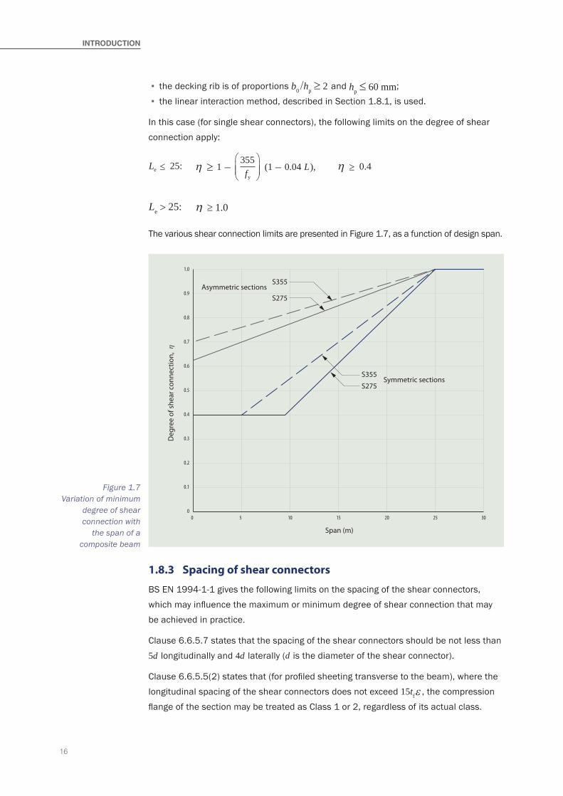
For symmetric steel sections, the general limit on the degree of shear connection is defined in BS EN 1994-1-1, §6.6.1.2 as:
Le 25:≤ 355fy
η 1 (0.75 0.03 ),Le≥ − − η 0.4≥
Le > 25: ≥ 1.0η
where:
Le is the distance between points of zero bending moment (beam span for simply supported beams), in metres.
The influence of the steel strength, fy is introduced because of the higher strains, and hence deformation demands, in plastic design using higher strength steels.
These limits may also be used when the section is asymmetrical with top flange area which exceeds that of the bottom flange.
For asymmetric steel sections in which the bottom flange area equals three times the top flange area, the minimum degree of shear connection is defined by:
Le 20:≤ 355fy
η 1 (0.30 0.015 ),Le≥ − − η 0.4≥
Le > 20: ≥ 1.0η
For steel sections in which the ratio of flange areas is between the limits of 1 and 3, linear interpolation between the above shear connection limits is permitted.
A relaxation of the degree of shear connection is permitted when all the following conditions are met:
▪ the studs have an overall length after welding not less than 76 mm and a nominal shank diameter of 19 mm;
▪ the steel section is rolled or welded I-sections or H-sections with equal flanges; ▪ the concrete slab is composite with profiled steel decking that spans perpendicular to the beam and the concrete ribs are continuous across the beam;
▪ there is one stud per rib of the decking;
16
INTrOdUCTION
1.8.3 Spacing of shear connectors
BS EN 1994-1-1 gives the following limits on the spacing of the shear connectors, which may influence the maximum or minimum degree of shear connection that may be achieved in practice.
Clause 6.6.5.7 states that the spacing of the shear connectors should be not less than 5d longitudinally and 4d laterally (d is the diameter of the shear connector).
Clause 6.6.5.5(2) states that (for profiled sheeting transverse to the beam), where the longitudinal spacing of the shear connectors does not exceed 15tfε , the compression flange of the section may be treated as Class 1 or 2, regardless of its actual class.
▪ the decking rib is of proportions b0 /hp ≥ 2 and hp ≤ 60 mm; ▪ the linear interaction method, described in Section 1.8.1, is used.
In this case (for single shear connectors), the following limits on the degree of shear connection apply:
Le 25:≤ 355fy
η 1 (1 0.04 ),L≥ − − η 0.4≥
Le > 25: ≥ 1.0η
The various shear connection limits are presented in Figure 1.7, as a function of design span.
0 5 10 15 20 25 300
0.1
0.2
0.3
0.4
0.5
0.6
0.7
0.8
0.9
1.0
Asymmetric sections
Symmetric sections
ηD
egre
e of
she
ar c
onne
ctio
n,
Span (m)
S275
S355
S275
S355
Figure 1.7 Variation of minimum
degree of shear connection with
the span of a composite beam

17
Clause 6.6.5.5(3) states that the maximum longitudinal spacing of the shear connectors should not be greater than the lesser of 6 times the slab thickness and 800 mm.
Clause 6.6.5.6(2) states that the edge distance (defined as from the edge of the shear connector to the tip of the flange) should not be less than 20 mm.
Clause 6.6.5.2(2) states that if cover is required (for durability), the nominal cover to the top of the shear connectors should not be less than 20 mm, or as recommended by BS EN 1992-1-1 Table 4.4 for reinforcement, less 5 mm. If cover is not required, the top of the connector may be flush with the upper surface of the slab.
Clause 6.6.5.7(5) states that the minimum flange thickness should not be less than 0.4 × stud diameter for adequate welding, and to avoid a reduction in shear connector resistance due to flange bending.
1.9 Transverse reinforcement
The requirement for transverse reinforcement in the slab perpendicular to the axis of the beam ensures an effective transfer of force from the shear connectors into the slab without splitting the concrete longitudinally.
BS EN 1994-1-1, §6.6.6.2(1) states that the design resistance to longitudinal shear should be determined in accordance with EN 1992-1-1, §6.2.4. That method uses a concrete strut analogy in which the reinforcement maintains equilibrium by tying action across the beam. The tensile force in the reinforcement may be based on a 1:2 to 1:1 dispersion angle from the longitudinal shear connector force into the slab. Therefore, the amount of transverse reinforcement is directly linked to the number of shear connectors provided and their design resistance. The upper bound to the force that can be developed is based on the compression resistance of the block of concrete in front of the shear connectors. BS EN 1994-1-1, §6.6.6.3(1) states that the minimum amount of transverse reinforcement should be determined in accordance with BS EN 1992-1-1, §9.2.2(5).
For continuous composite slabs that are designed as simply supported, BS EN 1994-1-1, §9.8.1(2) requires a minimum percentage of reinforcement of 0.2% of the cross sectional area of the slab topping for unpropped construction. The amount of reinforcement should be increased across the beams in the following cases:
▪ for propped construction (where 0.4% of the slab topping is the recommended minimum area of reinforcement according to §9.8.1(2));
▪ in the high shear region of primary beams; ▪ where the required fire resistance period is more than 60 minutes; ▪ where heavy local loads act on the slab; ▪ at long openings, where local cracking may occur in the slab.

18
19
2.1 General
The influence of large or closely spaced web openings on the behaviour of a composite beam is complex. There are many factors that may control failure:
▪ Whether the opening is in a high shear or a high bending zone. ▪ Whether the beam is uniformly loaded or point-loaded. ▪ The shape of the openings i.e. circular, rectangular or elongated circular. ▪ The position of the opening in the depth of the section. ▪ The spacing of the openings (interaction effects may occur in the web-post between the openings).
▪ The asymmetry of the steel section (in terms of the ratio of bottom to top flange areas). ▪ The longitudinal shear force acting on the slab at the opening. ▪ The slenderness of the web (which influences its buckling resistance).
The transfer of shear across openings occurs by Vierendeel (or four corner) bending. In a composite beam, the resistance to Vierendeel bending is increased by local composite action between the top Tee (web-flange section) and the slab (which can increase the local bending resistance of the Tee by a factor of 2 to 3). This local composite action permits larger openings to be designed in a composite beam than in a similar non-composite steel beam.
In this publication, the design method is based on an analysis according to first principles that is compatible with BS EN 1993-1-1 [6] and BS EN 1994-1-1 [7]. The method has been validated by finite element analyses and calibration against measurements from a major series of tests on full-scale beams [23].
Beams, with or without openings, should be designed to satisfy the design requirements at the ultimate and serviceability limit states, including the construction condition. The effect of large web openings leads to additional local design verification: the additional considerations are described in this publication.
Design prinCipLes for weB openings
20
deSIgN PrINCIPLeS
2.2 Design of unperforated composite beams
A simply supported unperforated composite beam is designed to provide:
▪ Bending resistance at the point of maximum moment. ▪ Shear connection between the steel beam and the concrete slab. ▪ Shear resistance at the supports. ▪ Resistance to the combinations of moment and shear along the beam. ▪ Local resistance at the connections and at point loads. ▪ Adequate transverse reinforcement given the number of shear connectors.
Composite behaviour is achieved by shear connection between the steel beam and the concrete slab. The design bending resistance depends on the section classification of the beam, which determines whether elastic or plastic section properties may be used for global bending resistance. Section classification is a function of the proportions of the flanges and web in compression. Composite beams generally may be treated as Class 1 or 2 in positive (sagging) bending because the plastic neutral axis lies close to or, within the top flange. The bending resistance also depends on the effective width of slab acting with the beam and on the degree of shear connection.
The shear connection may be either ‘full’ or ‘partial’. For full shear connection, the plastic bending resistance of the composite section can be developed at the point of maximum moment. For partial shear connection, the degree of shear connection must satisfy the limits of BS EN 1994-1-1 [7], as discussed in Section 1.8.2, and the bending resistance is reduced. The shear connectors should be distributed in such a way that the bending resistance is satisfied at all points in the span.
At the serviceability limit state, it is also necessary to verify:
▪ The deflection of the composite beam due to imposed loads and other loads applied to the composite section.
▪ The total deflection, including the deflection of the steel beam due to its own self weight and that of the concrete (when the beam is unpropped during construction).
▪ The vibration performance of the floor, which may be assessed according to SCI publication P354 [24].
2.3 Design of beams with large openings
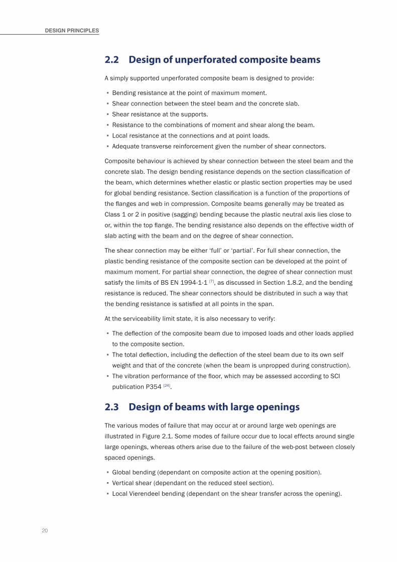
The various modes of failure that may occur at or around large web openings are illustrated in Figure 2.1. Some modes of failure occur due to local effects around single large openings, whereas others arise due to the failure of the web-post between closely spaced openings.
▪ Global bending (dependant on composite action at the opening position). ▪ Vertical shear (dependant on the reduced steel section). ▪ Local Vierendeel bending (dependant on the shear transfer across the opening).
21
▪ Web-post horizontal shear (which may govern for closely spaced openings). ▪ Web-post bending (which may govern between closely spaced rectangular openings). ▪ Web-post buckling (dependent on the slenderness of the web-post and the shear resistance of the web-post between adjacent openings).
▪ Shear buckling (which may govern for slender webs).
The local flexibility due to shear and bending deformation may also be significant for large openings, and this is taken into account in serviceability calculations and in the Vierendeel bending check – see Section 6.1.
2.4 Design model
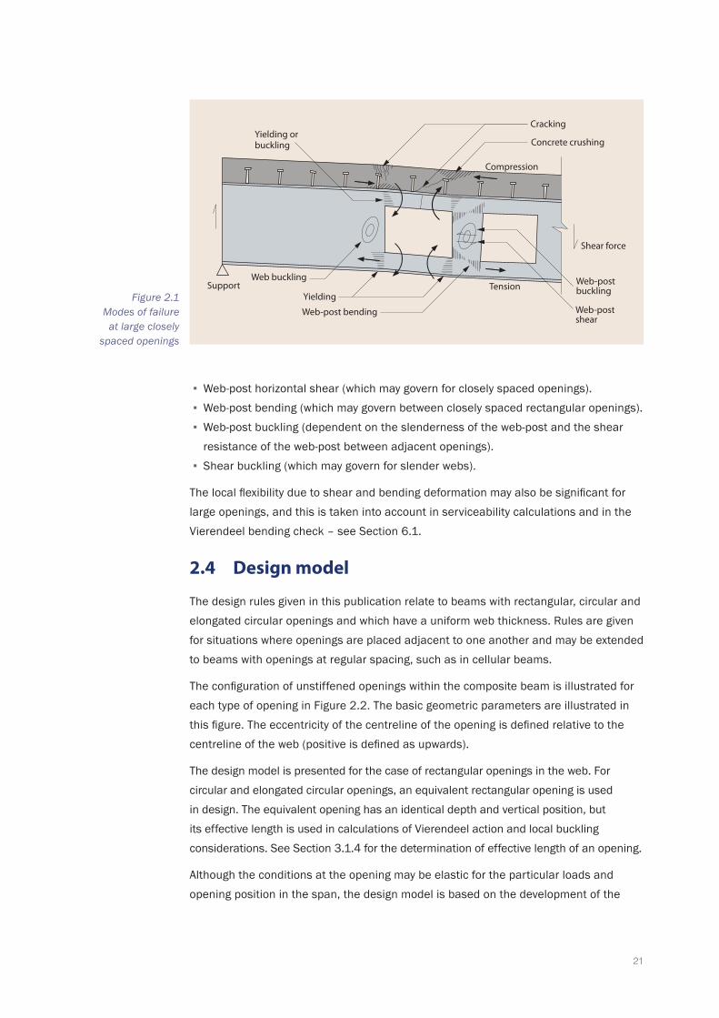
The design rules given in this publication relate to beams with rectangular, circular and elongated circular openings and which have a uniform web thickness. Rules are given for situations where openings are placed adjacent to one another and may be extended to beams with openings at regular spacing, such as in cellular beams.
The configuration of unstiffened openings within the composite beam is illustrated for each type of opening in Figure 2.2. The basic geometric parameters are illustrated in this figure. The eccentricity of the centreline of the opening is defined relative to the centreline of the web (positive is defined as upwards).
The design model is presented for the case of rectangular openings in the web. For circular and elongated circular openings, an equivalent rectangular opening is used in design. The equivalent opening has an identical depth and vertical position, but its effective length is used in calculations of Vierendeel action and local buckling considerations. See Section 3.1.4 for the determination of effective length of an opening.
Although the conditions at the opening may be elastic for the particular loads and opening position in the span, the design model is based on the development of the
Support
Compression
Shear force
Tension
Web-post shear
Yielding orbuckling
Web buckling
Cracking
Concrete crushing
Yielding
Web-post buckling
Web-post bendingFigure 2.1
Modes of failure at large closely
spaced openings
22
deSIgN PrINCIPLeS
elastic or plastic resistances of the elements, depending on the section classification, which are compared to the internal forces and moments.
The design resistance at the ultimate limit state is discussed in Section 3 for common cases, where the opening is located centrally within the depth of the web. The case where the openings are asymmetric in the depth of the beam is discussed in Section 4. When openings are very long, they may be stiffened horizontally above and below the opening. The design of stiffened openings is discussed in Section 5. Design for the serviceability limit state is discussed in Section 6. Design resistances for special cases are discussed in Section 7.
2.5 Assumptions in the design model
The distribution of internal forces around a large web opening is very complex and therefore certain simplifying assumptions have to be made for practical design, as follows:
▪ The vertical shear force is established at the higher shear side for a uniformly loaded beam, in order to take account of local loading over the opening. For a point loaded beam, the shear force is constant over the opening length.
▪ The tensile force in the bottom Tee is established from the design moment acting at the centreline of the opening. This is conservative for all design cases, as the position of zero bending moment in the Tees is towards the lower moment side of the opening as a result of plastic redistribution.
e o o
o
o
f,t
e
o
o
f
w b
t
o
f,b
f,t
o
f,b
o�o
wt
wb
wt
wb
h
= h s
�s s
h
e
t
t
s
h
e
t
h
h
h t
b
t
h
h
h
h
r
Figure 2.2 Configuration of
openings of various shapes
23
▪ For compatibility with the calculation of the tensile force in the bottom Tee, the compression force in the slab is established based on the number of shear connectors placed up to the centreline of the opening.
▪ Having established the bending resistance of the composite cross section at the centreline of the opening, the increase in bending resistance across the opening (Vierendeel bending) is established from the combined bending resistances of the Tees plus a component due to local composite action of the top Tee acting with the slab. This depends on the number of shear connectors placed over the opening.
▪ The plastic or elastic bending resistances of the web-flange (Tee) sections depend on the section classification and are reduced for coexisting shear and axial forces, based on the forces calculated as above.
▪ A relatively small vertical shear force acts in the slab at the opening, whose magnitude is limited by punching shear and pull-out of the shear connectors.
▪ The vertical shear force acting on the opening is resisted mainly by the top Tee, as the bottom Tee resists tension due to the design moment. It is conservative to consider initially that all the design shear is resisted by the top Tee and slab, which simplifies the design process.
▪ The Vierendeel bending resistance due to local composite action is limited partly by tension in the shear connectors at the end of the opening. This can be taken into account by reducing the design resistance of the shear connection in long openings.
▪ The forces developed in the web-post between openings are based on the change in forces between the centreline of adjacent openings. The web-post buckling model relates to the longitudinal shear force and moment in the web-post, which is increased due to asymmetry in the web-post position in the beam depth.
2.6 General guidance on positioning of openings
The geometric limits given in Table 2.1 should normally be observed when providing openings in the webs of composite beams. They are practical limits for beams within the scope of the publication. Openings that exceed these limits may be used, provided the design is justified by appropriate calculations, based on the principles of this publication.
At the initial design stage, the following approximations may be used to determine the effect of an opening on the bending resistance of a composite beam:
Mo,Rd = MRd (1 - 0.35ho/h) for unstiffened openings
Mo,Rd = MRd (1 - 0.2ho/h) for horizontally stiffened openings
where:MRd is the bending resistance of the unperforated composite beamMo,Rd is the bending resistance of the composite beam at the openingho is the depth of the openingh is the depth of the steel beam.

24
deSIgN PrINCIPLeS
2.7 Design of non-composite beams with large openings
The design of non-composite beams with large web openings may be carried out using essentially the same model and design procedures as are set out in this publication for composite beams but ignoring the contribution of the slab. The principal difference is that, in a non-composite beam, the top Tee resists compression due to global bending (the slab resists most or all of the compression in a composite beam) and this means that the top Tee is less effective in resisting Vierendeel bending and shear.
Composite beams constructed without propping in the construction stage are verified as non-composite beams at that stage.
PArAMeTerLIMIT
COMMeNT ON LIMITCIrCULAr OPeNINg
reCTANgULAr OPeNINg
Max. depth of opening:
≤ 0.8h ≤ 0.7h Experience shows this to be a practical limit for economic design. This is consistent with the other geometrical limits below.
Min. depth of Tees: ≥ tf + 30 mm ≥ 0.1h Practical limit, based on draft Annex N of ENV 1993-1-1:1992.
Min. depth of Top Tee:
As above As above and ≥ 0.1oif unstiffened
To limit local deformation and stability of the top Tee during construction.
Max ratio of depth of Tees: Asymmetry of opening position can cause web-post moments. It is preferable to provide an upward (positive) eccentricity of the opening in the web depth.
hb/ht ≤ 3 ≤ 2hb/ht ≥ 0.5 ≥ 1
Max. unstiffened opening length, o
— ≤ 1.5ho high shear* The limit of the aspect ratio, o/ho, limits the deformation across the opening and also tension in the shear connectors. Stricter limits are required for openings in high shear regions*.
— ≤ 2.5ho low shear
Max. stiffened opening length, o
— ≤ 2.5ho high shear*
— ≤ 4ho low shear
Min. width of web-post: The design of the web-posts is subject to further checks. It is recommended that stricter limits are adopted for openings in high shear regions*.
- Low shear regions
≥ 0.3ho ≥ 0.5o
- High shear regions*
≥ 0.4ho ≥ o
Corner radius of rectangular openings:
— ro ≥ 2tw
but ro ≥ 15 mmPre-drilled holes at the corners of the opening ensure no over-cutting and avoid a reduction in local plastic resistance of the Tee.
Min. width of end-post, se:
≥ 0.5ho ≥ o
and ≥ h
The minimum width of web-post depends also on the type of end connection and the build-up of forces in the shear connectors.
Min. horizontal distance to point load: The distance to the point load is measured from the nearer edge of the opening. A separate check is required on web buckling at point load positions.
– no stiffeners ≥ 0.5h ≥ h– with stiffeners ≥ 0.25ho ≥ 0.5ho
* A high shear region is where the design shear force is greater than half the maximum value of design shear force acting on the beam.
Table 2.1 Practical geometric
limits for beams with web openings

25

26

27
This Section discusses the determination of the local resistance of beams with unstiffened openings at the ultimate limit state (ULS). In this Section, the openings are considered to be located centrally within the depth of the web. The effect of eccentric location of the openings is discussed separately in Section 4, and stiffened openings are discussed in Section 5.
Sections 3.1 to 3.4 discuss effects and resistances at an individual opening; Section 3.5 discusses effects and resistances at the web-post between adjacent openings and Section 3.6 considers the reduction in shear buckling resistance of a slender web adjacent to an unstiffened opening.
3.1 Design effects at openings
3.1.1 Rectangular openings
The design forces and moments acting around an opening in the web of a composite beam with a single rectangular opening are shown in Figure 3.1. Under the action of
Design resistanCe of Beams with unstiffeneD openings
Mvb,Ed
Mvt,Ed Mvt,Ed
Mvb,Ed
Mvt,Ed + Mvb,Ed
Mvt,Ed + Mvb,Ed + Mvc,Ed
VEd�o
BA
�o
MEd
B
VEdVEd
Nb,Ed
NC,Ed +
Forces at: A
NC,Ed
NC,Ed
Pointload
Nb,Ed − NC,Ed
Nb,Ed
(Nb,Ed − NC,Ed) −
Bendingmoment
NC,Ed
NC,Ed
Figure 3.1 Equilibrium of forces
at a single opening
28
UNSTIFFeNed OPeNINgS
the positive (sagging) bending moment, a tensile force is developed in the bottom Tee (i.e. the web-flange section), which remains constant across the width of the opening. This force is balanced by a compression force in the concrete and, depending on the proportions of the slab and the Tees, a compression force in the top Tee. Generally, the top Tee is not assumed to develop any tensile force, as it would require excessively large plastic strains to do so.
The compressive force in the concrete is developed through shear connectors welded to the top flange of the beam. The shear connectors are usually placed uniformly along the beam or, in the case of beams subject to point loads, in groups of uniform spacing dependant on the shear force. In some cases, the force that can be transferred from the beam to the slab is limited by the number of shear connectors provided; this is known as partial shear connection (see Sections 1.8).
The variation in bending moment across the opening due to the design shear force is achieved by ‘Vierendeel action’, resulting in local bending of the Tees in the four corners. In the top Tees, the Vierendeel bending is also resisted by local composite action with the slab.
The global bending resistance is verified at the centre of the opening. Assuming zero Vierendeel moments at that point, the axial force in the bottom Tee thus depends on the bending moment at that position. In reality, this will not always correspond to the point of zero bending in the Tees, which will actually move towards the lower moment side of the opening, when the component of Vierendeel bending resistance due to local composite action is relatively high and plastic redistribution occurs. However, this assumption simplifies the analysis and results in a conservative prediction of resistance.
3.1.2 Distribution of internal forces
At the ultimate limit state, failure occurs due either to the formation of plastic hinges around the opening in zones of high shear and low moment or as a result of tensile yielding in the bottom Tee, in zones of low shear and high moment. Each of the Tees is subject to combined axial force, bending and shear, which affects the development of plasticity and this allows some opportunity for redistribution of Vierendeel moments around the opening. The effect of this behaviour is to make an accurate analysis of the local design forces highly complex, and certain simplifications are necessary.
Therefore, to determine the distribution of internal forces at an opening, certain simplifying assumptions are made, as follows:
▪ The axial forces in the Tees and in the concrete are based on plastic analysis principles at all load levels, i.e. rectangular stress blocks are considered.
▪ The compression force in the slab is based on the shear connection provided from the support to the centreline of the opening.
▪ At the opening, vertical shear is resisted by the two Tee sections and by the concrete slab due to the local composite action at the openings.

29
▪ The shear force in the slab at the opening is based on its punching shear resistance. ▪ The distribution of shear between the Tees is based on their resistance to Vierendeel bending. Local composite action increases the Vierendeel bending resistance of the top Tee. Conservatively, the shear resisted by the bottom Tee can be neglected for large openings.
3.1.3 Minimum values of co-existent shear and bending
It is also necessary to ensure that the design value of the shear force VEd used to determine Vierendeel bending effects takes into account the possibility of non-uniformity in the loading during construction and in service. Therefore, it is recommended that, at any opening, the minimum combinations of design values of shear and co-existing bending moment given in Table 3.1 are considered for zones of the beam subject to low shear.
3.1.4 Circular and elongated openings
Generally, circular and elongated openings may be treated in the same way as a rectangular opening, i.e. the forces are carried across the opening by Vierendeel action. For consideration of Vierendeel bending, the effective length of the equivalent rectangular opening may be taken as:
e = 0.45ho for circular openings
or (4)
e = o − 0.55ho for elongated openings
where:o is the length of the elongated openingho is the diameter of the circular opening or of the ends of an elongated opening.
For circular openings, the effective height of the equivalent rectangular opening, for determining the Vierendeel bending resistance of the Tees, may be taken as 0.9ho.
The effective length and height for circular openings has been justified by research on non-composite beams with circular openings [25]. The effective length for elongated openings is based on that for a circular opening plus the distance between the two semi-circular ends of the opening.
CONdITION SheAr FOrCe BeNdINg MOMeNT
Construction (steel section) 0.25VEd,max 0.75MEd,max
Composite Condition 0.15VEd,max 0.85MEd,max
VEd,max is the maximum shear force at the supports for the relevant design situationMEd,max is the maximum moment in the span for the relevant design situation
Table 3.1 Minimum combinations of design effects to be
considered at an opening
30
UNSTIFFeNed OPeNINgS
3.2 Bending resistance at the opening
The bending resistance of the composite beam cross section should be verified at the centre of the opening. This verification determines the tensile force in the bottom Tee (which will affect its bending resistance and also that of the web-post – see further discussion in Section 3.5).
Generally, the plastic bending resistance of the perforated cross section can be utilized, although this depends on the classification of the top Tee and whether bending resistance is limited by partial shear connection. Sections are classified generally in accordance with BS EN 1993-1-1 [6]. Class 1 and 2 sections permit use of plastic bending resistance and Class 3 and 4 sections are restricted to elastic bending resistance.
3.2.1 Classification of the cross section
In an unperforated composite beam, the plastic neutral axis normally lies in or above the top flange of the steel section; only when using a fabricated section with a much smaller top flange than bottom flange will the plastic neutral axis lie in the web. This is equally true for a perforated section, as the plastic neutral axis is higher than in the unperforated section. Consequently, the perforated composite section will generally be Class 2 or better. If the plastic neutral axis of an asymmetric section is in the web of the top Tee, the top flange in compression may be treated as at least Class 2, even if its outstand is Class 3, if it is adequately connected to the slab; this requires shear connectors within the width of each outstand (i.e. a single line of connectors along the beam centreline is ineffective for this purpose) at a spacing that satisfies the limits in BS EN 1994-1-1, §6.6.5.
Local Vierendeel action in the bottom Tee may cause net compressive stress in the Tee at one end of the opening, but this does not require consideration for classification of the whole beam section.
3.2.2 Equilibrium of internal forces providing bending resistance
To determine the plastic bending resistance at the centreline of the opening, the forces in the Tees and the slab must be in equilibrium. Two situations are possible: with the plastic neutral axis in the slab and with the plastic neutral axis in the top Tee. The two situations are illustrated in Figure 3.2 and are discussed separately below.
Case 1: Nc,Rd > NbT,Rd (p.n.a. in slab)
In this case, the compression resistance of the full depth of the effective width of slab is greater than the tension resistance of the bottom Tee. For this situation, it may be considered that the p.n.a. is within the slab at a height such that all the concrete above it develops a stress of 0.85fcd (where fcd is as defined in BS EN 1994-1-1).
The tensile resistance of the bottom Tee is given by:
NbT,Rd A fbT y
M0
=γ
(5)

31
where:AbT is the cross sectional area of the bottom Teefy is the design value of the yield strength of steel.
The compression resistance of the full thickness of the slab at the position of the opening is the lesser of the compression resistance of the effective width of slab and the resistance provided by the shear connectors between the end of the beam and the centreline of the opening. For a beam with profiled decking with ribs transverse to the beam, the resistance is given by:
Nc,Rd f b h n Pcd eff,o c sc Rd= { }min . ;0 85 (6)
where:fcd is the design strength of the concrete (= fck/γC , with fck and γC as defined in
BS EN 1992-1-1 and its National Annex)beff,o is the effective slab width at the opening, as defined in Section 3.2.3hc is depth of the concrete topping (hc = hs − hd)hs is the slab depthhd is the overall depth of the decking profilensc is the number of shear connectors placed over the distance from the nearer
support to the centreline of the opening (see discussion in Section 3.2.4)PRd is the design resistance of the shear connectors used with profiled sheeting
(i.e. the value of PRd given in Section 1.6.1 multiplied by kt or k
as given in Section 1.6.2).
The plastic bending resistance is then given by:
Mo,Rd N h z h zbT,Rd eff t s c= + + −( )0 5. (7)
0.85 0.85cd cd
f fyd yd
hc
be�
a. Tension in topTee ignored
b. Compression in top Tee
N −b,Rd
N
Nb,Rd
Nc,RdN
b,Rd
Nb,Rd
Nc,RdN
b,Rd
Nc,Rd
c,Rd
Nb,Rd
f fp.n.a.
Figure 3.2 Plastic stress blocks
in a perforated composite beam

32
UNSTIFFeNed OPeNINgS
where:heff is the effective depth of the beam between the centroids of the Teeszt is the depth of the centroid of the top Tee from the outer edge of the flangezc is the depth of concrete in compression, which is given by:
Nf bc,z =c h≤ c
Rd
cd eff,o0 85.
Using this model, it follows that for a given design moment, MEd, the axial force in the bottom Tee is given by:
NbT,Ed M
=h z h z
Ed
eff t s c+ + −( )0 5. (8)
As a simplification, zc may be taken as equal to hc in this expression.
For a beam with decking parallel to the beam, the above expressions should be modified appropriately if the p.n.a. lies below the topping.
Case 2: Nc,Rd < NbT,Rd (p.n.a. in top Tee)
In this case, the compression resistance of the full depth of the effective width of slab is less than the tension resistance of the bottom Tee and equilibrium is achieved by developing compression in the top Tee. For this situation, it is conservative to assume that the top Tee is uniformly stressed and subject to a force equal to the difference between the tension resistance of the bottom Tee and the compression resistance of the slab, i.e. it provides a resistance equal to NbT,Rd − Nc,Rd.
where:NbT,Rd is defined in (5) and Nc,Rd is as defined in (6).
With this assumption, the plastic bending resistance is given by:
Mo,Rd N h N z h hbT,Rd eff c,Rd t s c= + + −( )0 5. (9)
where:
heff, zt, hs and hc are all as defined above.
It is also necessary to verify that for highly asymmetric sections, the compression resistance of the top Tee is adequate, as follows:
A fNbT,Rd – Nc,Rd≥
tT y
M0γ
where:AtT is the cross sectional area of the top Tee.
To determine the force in the bottom Tee for this case, expression (8) may be used unless this gives NbT,Ed > Nc,Rd, in which case the force may be taken as:
33
NbT,Ed M N z h h
hEd c,Rd t s c
eff
=− + −( )0 5. (10)
where:Nc,Rd is as given by expression (6).
For a beam with decking parallel to the beam, the above expressions should be modified appropriately to take account of the area of concrete in the full depth of slab.
3.2.3 Effective width of slab at an opening
For openings close to the supports, the effective slab width is less than at mid-span. As noted in Section 1.7, BS EN 1994-1-1, §5.4.1.2(6) gives a formula for the effective width at the end of the span. For a simply supported span with a sufficient available width of slab on both sides, and ignoring b0, the effective slab width acting with the beam at an opening, at a distance x from the support is given by:
beff,o = 3Le/16 + x/4 for x ≤ Le/4 (11)
and
beff,o = Le/4 for x > Le/4
where:Le is the effective span.
3.2.4 Shear connection at an opening
When calculating the bending resistance at an opening, the number of shear connectors should be taken as the number from the support to the centreline of the opening. This is used to calculate the force in the bottom Tee, which influences its Vierendeel bending resistance.
The minimum shear connection required at an opening is determined by the need to develop a compression resistance Nc,Rd that will result in adequate bending resistance at critical cross sections, such as openings. For uniformly loaded composite beams, the shear connection requirements at intermediate positions between the support and the maximum moment position are usually satisfied by the minimum degree of shear connection rules defined in BS EN 1994-1-1 for unperforated sections. However, where point loads are placed close to the supports, the bending resistance of the perforated beam at the first opening position may be critical to the design.
For the composite design of beams with large openings close to the supports, it is likely that a shear connection resistance equal to 40% of the tensile force developed in the bottom Tee (i.e. Nc,Rd ≥ 0.4NbT,Ed ) will be required to ensure adequate composite bending resistance. This is not a minimum degree of shear connection limit for the beam, but aims to ensure adequate composite action close to supports. If this is not achieved by the application of current minimum degree of shear connection rules, then additional
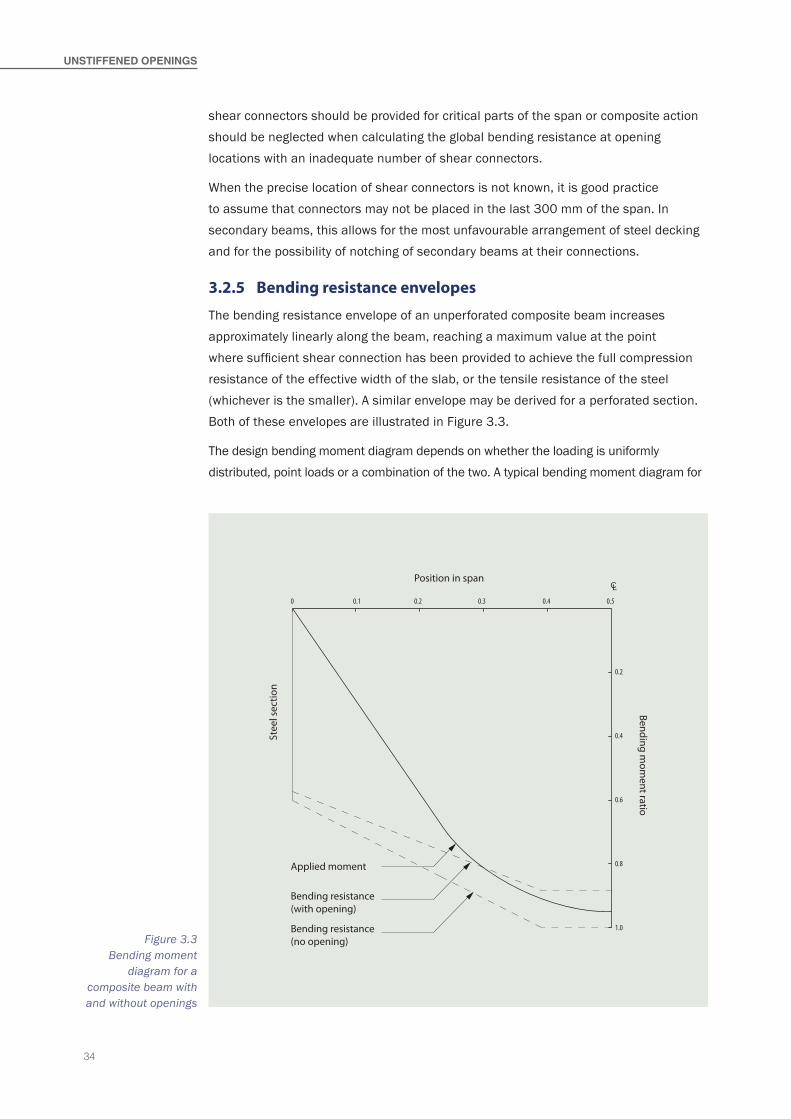
34
UNSTIFFeNed OPeNINgS
shear connectors should be provided for critical parts of the span or composite action should be neglected when calculating the global bending resistance at opening locations with an inadequate number of shear connectors.
When the precise location of shear connectors is not known, it is good practice to assume that connectors may not be placed in the last 300 mm of the span. In secondary beams, this allows for the most unfavourable arrangement of steel decking and for the possibility of notching of secondary beams at their connections.
3.2.5 Bending resistance envelopes
The bending resistance envelope of an unperforated composite beam increases approximately linearly along the beam, reaching a maximum value at the point where sufficient shear connection has been provided to achieve the full compression resistance of the effective width of the slab, or the tensile resistance of the steel (whichever is the smaller). A similar envelope may be derived for a perforated section. Both of these envelopes are illustrated in Figure 3.3.
The design bending moment diagram depends on whether the loading is uniformly distributed, point loads or a combination of the two. A typical bending moment diagram for
0 0.1 0.2 0.3 0.4 0.5
L
0.2
0.4
0.6
0.8
1.0
Position in spanC
Bending mom
ent ratio
Stee
l sec
tion
Bending resistance(with opening)
Applied moment
Bending resistance(no opening)Figure 3.3
Bending moment diagram for a
composite beam with and without openings
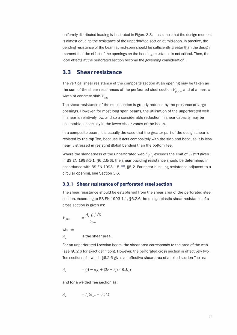
35
uniformly distributed loading is illustrated in Figure 3.3; it assumes that the design moment is almost equal to the resistance of the unperforated section at mid-span. In practice, the bending resistance of the beam at mid-span should be sufficiently greater than the design moment that the effect of the openings on the bending resistance is not critical. Then, the local effects at the perforated section become the governing consideration.
3.3 Shear resistance
The vertical shear resistance of the composite section at an opening may be taken as the sum of the shear resistances of the perforated steel section Vpl,o,Rd and of a narrow width of concrete slab Vc,Rd.
The shear resistance of the steel section is greatly reduced by the presence of large openings. However, for most long span beams, the utilisation of the unperforated web in shear is relatively low, and so a considerable reduction in shear capacity may be acceptable, especially in the lower shear zones of the beam.
In a composite beam, it is usually the case that the greater part of the design shear is resisted by the top Tee, because it acts compositely with the slab and because it is less heavily stressed in resisting global bending than the bottom Tee.
Where the slenderness of the unperforated web hw/tw exceeds the limit of 72ε/η given in BS EN 1993-1-1, §6.2.6(6), the shear buckling resistance should be determined in accordance with BS EN 1993-1-5 [30], §5.2. For shear buckling resistance adjacent to a circular opening, see Section 3.6.
3.3.1 Shear resistance of perforated steel section
The shear resistance should be established from the shear area of the perforated steel section. According to BS EN 1993-1-1, §6.2.6 the design plastic shear resistance of a cross section is given as:
Vpl,Rd A fv y
M0
=3
γ
where:Av is the shear area.
For an unperforated I-section beam, the shear area corresponds to the area of the web (see §6.2.6 for exact definition). However, the perforated cross section is effectively two Tee sections, for which §6.2.6 gives an effective shear area of a rolled section Tee as:
Av = (A - bf tf + (2r + tw) × 0.5tf )
and for a welded Tee section as:
Av = tw (hw,T - 0.5tf )
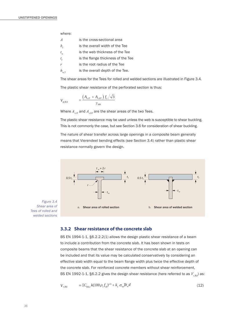
36
UNSTIFFeNed OPeNINgS
where:A is the cross-sectional areabf is the overall width of the Teetw is the web thickness of the Teetf is the flange thickness of the Teer is the root radius of the Teehw,T is the overall depth of the Tee.
The shear areas for the Tees for rolled and welded sections are illustrated in Figure 3.4.
The plastic shear resistance of the perforated section is thus:
Vpl,Rd A A fv,tT v,bT y
M0
=+( ) 3
γ
Where Av,tT and Av,bT are the shear areas of the two Tees.
The plastic shear resistance may be used unless the web is susceptible to shear buckling. This is not commonly the case, but see Section 3.6 for consideration of shear buckling.
The nature of shear transfer across large openings in a composite beam generally means that Vierendeel bending effects (see Section 3.4) rather than plastic shear resistance normally govern the design.
t
t
t
r
0.5 t
w + 2
f
w
f
r
t
t
0.5 t f
w
f
a. Shear area of rolled section b. Shear area of welded section
Figure 3.4 Shear area of
Tees of rolled and welded sections
3.3.2 Shear resistance of the concrete slab
BS EN 1994-1-1, §6.2.2.2(1) allows the design plastic shear resistance of a beam to include a contribution from the concrete slab. It has been shown in tests on composite beams that the shear resistance of the concrete slab at an opening can be included and that its value may be calculated conservatively by considering an effective slab width equal to the beam flange width plus twice the effective depth of the concrete slab. For reinforced concrete members without shear reinforcement, BS EN 1992-1-1, §6.2.2 gives the design shear resistance (here referred to as Vc,Rd) as:
Vc,Rd = [CRd,c k(100ρ1 fck)1/3 + k1 σcp]bwd (12)

37
with a minimum of:
Vc,Rd = [vmin + k1σcp]bwd (13)
where:CRd,c = 0.18/γc (as given in the National Annex to BS EN 1992-1-1)
k = 1 200+
d but ≤ 2.0 (with d in mm)
ρ1 = Ab d
sl
w
but ≤ 0.02
Asl is the area of tensile reinforcement provided by the crack control mesh, which extends ≥ (bd + d) beyond the section considered
d is the effective depth of the slab. Based on test performance of beams supporting slabs cast on trapezoidal composite decking, it is considered that the effective depth of the slab may be taken as equal to hc
bd is the design anchorage length of the tensile reinforcementk1 = 0.15 (as given in the National Annex to BS EN 1992-1-1)
σcp = N
< 0.2 fcdb hc,Ed
eff c
bw is the effective width of the concrete flange for shear = bf + 2hs,eff
bf is the flange width of the top Teehs,eff is the effective slab depth for punching shear ≈ 0.75hs
vmin = 0.035k3/2fck1/2 (recommended value given in UK National Annex).
For general design of composite beams, σcp may be neglected for openings placed close to beam supports, but may be a significant factor in high bending moment regions.
Effect of high shear force on global bending resistance
The effect of the high shear forces in the Tees is to reduce the effectiveness of the web for bending. The simple interaction formula given by BS EN 1993-1-1, §6.2.8 may be used to calculate the effect of high shear on global bending resistance. No reduction in bending resistance is required for ρ ≤ 0.5.
3.4 Bending resistance of Tee sections
Vierendeel bending occurs at the four corners of the opening and the stresses in the resistance model at each corner must be such as to maintain equilibrium across the opening; the stresses and associated forces are illustrated in Figure 3.5 for plastic resistance and Figure 3.6 for elastic resistance.
As noted in Section 3.1.4, circular and elongated openings may be represented by an equivalent rectangular opening.
38
UNSTIFFeNed OPeNINgS
3.4.1 Vierendeel bending resistances
Vierendeel bending is the means by which shear force is transferred across a large opening. The sum of the Vierendeel bending resistances at the four corners of the opening, plus the contribution due to composite action between the top Tee and the slab, must therefore not be less than the design value of the difference in bending moment from one side of the opening to the other due to that shear force; this may be expressed as:
2MbT,NV,Rd + 2MtT,NV,Rd + Mvc,Rd ≥ VEde (14)
where:MbT,NV,Rd is the bending resistance of the bottom Tee, reduced for coexisting axial
tension and shearMtT,NV,Rd is the bending resistance of the top Tee, reduced for coexisting axial
compression and shearMvc,Rd is the local composite Vierendeel bending resistance, as defined in Section 3.4.6VEd is the design value of the vertical shear force (taken as the value at the
lower moment side of the opening)e is the effective length of the opening for Vierendeel bending.
See Section 3.4.4 for guidance on determining MNV,Rd.
In practice, the Vierendeel bending resistances are usually higher than the values used in expression (14), due to strain hardening of the deformed steel at the corners of the opening. However, this effect is not taken into account in design.
The Vierendeel bending resistances depend on the classification of the webs of the Tees (see Section 3.4.2). Where the web is Class 3 or 4, only the elastic bending resistances can be used. However, the axial forces in the Tees (which reduce the bending resistance) are generally determined on the basis of ‘plastic’ stress blocks (as discussed in Section 3.2). It is considered conservative to use the axial forces determined from this plastic stress model, even when evaluating the elastic Vierendeel bending resistances.
3.4.2 Classification of the webs of Tees
The outstand of the web of the Tee may be classified depending on the effective length of Tee o,eff and the outstand depth ht or hb, as given in Table 3.2.
For this local buckling classification, the effective length of the opening is defined conservatively as:
o,eff = o for rectangular openings
or
o,eff = 0.7ho for circular openings (15)

39
or
o,eff = o − 0.3ho for elongated openings
This effective length takes account of the condition where the outstand of a top or bottom Tee is subject to compression over at least part of its length.
Co-existent axial compression due to global bending does not normally need to be considered in the top Tee because compressive stresses in the top flange of a composite beam due to global bending will be relatively small.
For the purpose of calculating the Vierendeel bending resistance, it is permissible to reduce the depth of a Class 3 web to that appropriate for the Class 2 limit, so that the resistance calculation may be based on plastic resistance of the reduced section, provided the flange is Class 1 or 2 (this reduction does not need to be applied to the consideration of the global bending resistance at the centre of the opening).
For a Class 4 web, the effective elastic section properties are calculated using the limiting value of hw for a Class 3 web.
For a non-composite beam, there will be significant compression in the top Tee and the above classification should not be used. The usual classification in accordance with BS EN 1993-1-1, §5.5.2, as an outstand in compression, should be used for the web of the Tee.
Effects of axial tension on section classification of bottom Tee
Tension in the bottom Tee modifies the section classification for unstiffened Tees and improves the classification of the section. Conservatively this may be ignored, to simplify the hand calculation process; use the classification in Table 3.2. Alternatively, the effect of tension may be taken into account, as follows.
Class 3 webs may be treated as Class 2 if the plastic stress block for the Tee section subject to the combined bending and tension is such that the depth of web in
CLASSLIMIT ON dePTh OF weB hw ACCOrdINg TO LeNgTh OF OPeNINg
o,eff ≤ 32ε tw 32ε tw < o,eff ≤ 36ε tw o,eff > 36ε tw
2 (no limit)
10hw ≤
1 322
ε
ε
t
t
w
w
o,eff
−
�
3 (no limit)
14hw ≤
1 362
ε
ε
t
t
w
w
o,eff
−
�
4 (no limit)
hw is the web depth of the top or bottom Tee, as relevant.
Table 3.2 Classification
of Tee webs
40
UNSTIFFeNed OPeNINgS
compression is limited to a maximum of 10ε tw. This requirement may be more simply expressed as:
NA f
bT,Ed
bT y M0γ20 2ε t
Aw
bT
≥ 1 − (16)
where:NbT,Ed is the axial tension in the bottom TeeAbT is the cross sectional area of the bottom Tee.
Class 4 webs may be treated as Class 3 when also subject to axial tension, provided that:
hwb ≤ 14
1 362
t
t
w
w
o,eff
′
−′
ε
ε�
if o,eff > 36twε′ (17)
where:
ε′ ε=γ
1 −
NA f
bT,Rd
b y M0
0.5
hwb is the depth of the web of the bottom Tee above the flange.
3.4.3 Effect of shear force on the bending resistance of Tees
The effect of the high shear forces in the Tees is to reduce the effectiveness of the web. However, the reduction of the web thickness for high shear influences the Vierendeel bending resistance of the Tees and in turn the distribution of shear.
As a first approximation, the following simple interaction formula may be used to calculate of the effective web thickness:
tw,eff = tw (1 - (2µ - 1)2) for µ > 0.5 (18)
No reduction in web thickness is required for µ ≤ 0.5.
where:µ is the utilisation of the cross section in shear = VEd/VRd
VEd is the design value of the shear force at the openingVRd is the shear resistance of the perforated cross section = Vc,Rd + Vt,Rd + Vb,Rd
Vc,Rd is the shear resistance of the concrete slab (see Section 3.3.2)Vt,Rd is the plastic shear resistance of the top TeeVb,Rd is the plastic shear resistance of the bottom Tee.
The resulting value of tw,eff is applied to the calculation on moment resistance for both tees.
The actual distribution of shear forces between the Tees depends on their Vierendeel bending resistances and these in turn may depend on the reduced effective web thickness. The utilization in shear may differ for the two Tees. See further comment in Section 3.4.4.
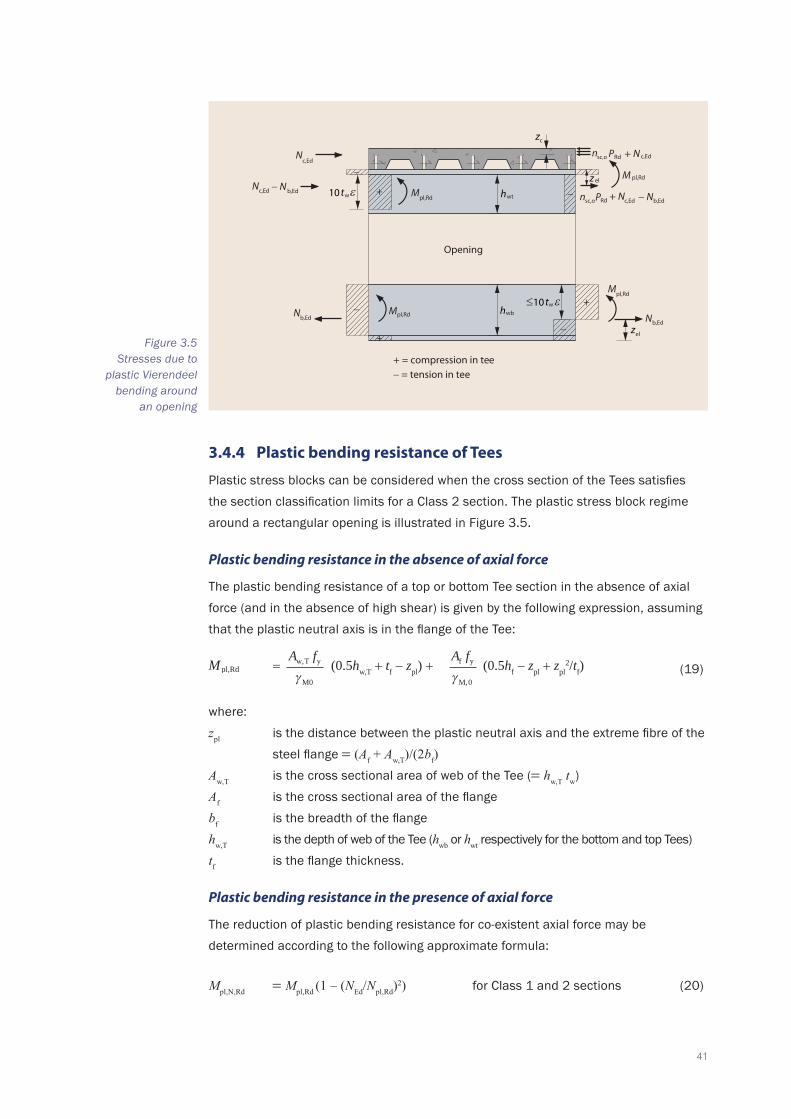
41
3.4.4 Plastic bending resistance of Tees
Plastic stress blocks can be considered when the cross section of the Tees satisfies the section classification limits for a Class 2 section. The plastic stress block regime around a rectangular opening is illustrated in Figure 3.5.
Plastic bending resistance in the absence of axial force
The plastic bending resistance of a top or bottom Tee section in the absence of axial force (and in the absence of high shear) is given by the following expression, assuming that the plastic neutral axis is in the flange of the Tee:
Mpl,Rd A fw,T y
M0γA ff y
M,0γ(0.5hw,T + tf − zpl) + (0.5hf − zpl + zpl
2/tf)= (19)
where:zpl is the distance between the plastic neutral axis and the extreme fibre of the
steel flange = (Af + Aw,T)/(2bf)Aw,T is the cross sectional area of web of the Tee (= hw,T tw)Af is the cross sectional area of the flangebf is the breadth of the flangehw,T is the depth of web of the Tee (hwb or hwt respectively for the bottom and top Tees)tf is the flange thickness.
Plastic bending resistance in the presence of axial force
The reduction of plastic bending resistance for co-existent axial force may be determined according to the following approximate formula:
Mpl,N,Rd = Mpl,Rd (1 – (NEd/Npl,Rd)2) for Class 1 and 2 sections (20)
c
sc,o
sc,o
w
Opening
el
+
−
−
−
+
+ −Rd
el
Rd
+ = compression in tee− = tension in tee
wt
wb
w
c,Ed
c,Ed b,Ed
b,Edb,Ed
c,Ed b,Ed
c,EdnN
− N N
N N
n P + N − N
P + N
pl,RdM
pl,RdM
pl,RdM
pl,RdM10
z
z
z
h
ht
10 t
Figure 3.5 Stresses due to
plastic Vierendeel bending around
an opening

42
UNSTIFFeNed OPeNINgS
where:Mpl,N,Rd is the reduced plastic resistance of the Tee taking account of axial forcesNpl,Rd is the axial resistance of the Tee (for a Tee in compression, the depth of a
Class 3 web may be reduced to the Class 2 limit, or a Class 4 web reduced to Class 3 respectively)
NEd is the design value of the axial force in the Tee due to the global bending action, either the compression force in the top Tee, NtT,Ed or the tension force in the bottom Tee, NbT,Ed.
For Case 1 in Section 3.2.2 (p.n.a. in the slab), NtT,Ed = 0 and NbT,Ed is given by expression (8). For Case 2 (p.n.a. in the top Tee) NbT,Ed is given by either expressions (8) or (10) (see discussion in Section 3.2.2) and the compression in the top Tee is given by NtT,Ed = NbT,Ed − Nc,Rd, where Nc,Rd is given by expression (6).
Reduction of bending resistance due to shear
As noted in Section 3.4.3, the utilization of the web of a Tee in shear may reduce its effective thickness for bending and axial resistances. The effective thickness tw,eff is given by (18) dependent on the utilization factor µ. The reduced cross-sectional area of web of the Tee (= hw,T tw,eff) is then used in (19) and this reduced plastic bending resistance is used in (20), leading to the plastic bending resistance of the Tee in the presence of axial force and shear, Mpl,NV,Rd.
However, the shear force which may be resisted by a Tee is limited by Vierendeel bending resistance of the Tee over the length of the opening. Therefore, a process of iteration is required to determine a shear force distribution between the top and bottom Tees that is compatible with the Vierendeel bending resistance. A procedure is needed to evaluate the interactions and to determine the distribution of shear between the Tees, as follows.
Distribution of shear between top and bottom tees
Conservatively Vb,Rd can be first set to zero to calculate µ and the associated effective web thickness tw,eff of the top Tee, as shown in Section 3.4.3. The plastic bending resistance of the top Tee MtT,NV,Rd can then be determined. The value of plastic bending resistance for the bottom Tee, MbT,NV,Rd may then be calculated for the same utilization factor and the associated shear force in the bottom Tee may be evaluated as:
Vb,Ed = 2MbT,NV,Rd/e (21)
After this, the coexisting shear force in the top composite Tee can then be evaluated as: Vt,Ed = VEd − Vb,Ed.
The adequacy of Vierendeel bending resistance is verified using expression (14).
If expression (14) is not satisfied at this stage, the utilization of the Tees may be determined from the calculated values of Vt,Ed and Vb,Ed and the bending resistances re-evaluated. A single iteration is generally adequate.

43
3.4.5 Elastic bending resistance of Tees
Elastic design should be used when one or both Tee sections are Class 3 (this includes Class 4 sections where an effective section that complies with Class 3 limits is considered). The elastic stress regime around an opening is shown in Figure 3.6. The limit on the effective depth of web in sections that would otherwise be Class 4 is conservatively taken as that for pure compression.
As noted previously, local composite action of the top Tee and the slab occurs due to the shear connectors placed over the opening, and is added to the elastic bending resistance of the Tees. For this reason, the point of zero bending is not at the centreline of the opening.
sc,o
Opening
Rd
el
c
+ = compression in tees
− = tension in tees
wt
wb
w
c,EdN
c,EdNN b,Ed −14t
Nb,Ed N b,Ed
z
n P + N c,Ed − N b,Ed
sc,o Rdn P + N c,Ed
el
>/pl,RdM
pl,RdMpl,RdM
pl,RdM
h
h
z
z
+
−
−
+ −
− +
ε
Figure 3.6 Stresses due to
elastic Vierendeel bending around
an opening
Elastic bending resistance in the absence of axial force
The elastic bending resistance of the top or bottom Tee section in the absence of axial force is given by:
M el,Rd A f h t z A f z t
h t zw,T yd w,T f el f yd el f
w,T f el
( . ) ( . )0 5 0 52 2+ − + −
+ −= (22)
where:zel is the distance from the centroid of the Tee to the extreme fibre of the
flange, given by:
zel A h t t A
A Aw,T w,T f f f
f w,T
( . ) .( )
0 5 0 5+ ++
=
Elastic bending resistance in the presence of axial force
The reduced elastic bending resistance is given by:
Mel,N,Rd = Mel,Rd (1 – (NT,Ed/NRd)) for Class 3 and 4 sections (23)

44
UNSTIFFeNed OPeNINgS
where:Mel,N,Rd is the elastic resistance of the Tee section (for the outstand of the web in
compression, the depth of a Class 4 web may be reduced to the Class 3 limit)NRd is the axial resistance of the Tee (for a Tee in compression, the depth of a
Class 3 web may be reduced to the Class 2 limit, or a Class 4 web reduced to Class 3 respectively)
NT,Ed is the design value of the axial compression or tension force in the Tee due to the global bending action.
Elastic bending resistance in the presence of high shear
Combined effects due to shear may be neglected in elastic design, provided the global shear resistance is satisfied.
3.4.6 Vierendeel resistance due to local composite action
A contribution to the Vierendeel bending resistance occurs due to local composite action of the top Tee with the slab. The magnitude of this component is dependent on the number of shear connectors placed directly over the opening. However, its magnitude is also influenced by the flexibility of the beam at the opening, and it is necessary to introduce a modification factor to avoid over reliance on local composite action for long openings.
The bending resistance due to composite action of the top Tee with the slab is given conservatively by:
Mvc,Rd = ∆Nc,Rd (hs + zt - 0.5hc )ko (24)
where:∆Nc,Rd is the compression force developed by the shear connectors placed over the
opening (= nsc,o PRd)nsc,o is the number of shear connectors placed over the openingPRd is the design resistance of the shear connectors used with profiled sheeting
(i.e. PRd as given in Section 1.6.1 multiplied by kt or k
as given in Section 1.6.2)hs is the overall depth of the slabzt is the depth of the centroid of the top Tee from the outer edge of the flange
(as an approximation, take zt = top flange thickness)hc is the depth of concrete above the decking profileko is a reduction factor due to the flexibility of the opening, which takes account
of second order effects together with the combination of shear and tension forces at the edge of the opening. Expressions for ko are given below.
For circular openings, nsc,o is calculated over the effective length of the opening e ( = 0.45ho ). However, because it is impossible to guarantee the exact position of the shear connectors over the opening, together with the fact that the zone of influence of the opening extends
45
outside the opening, it is recommended that the exact value of e divided by stud spacing is used to calculate nsc,o (rather than the integer value).
It is conservative to ignore composite action over the opening if the Vierendeel bending resistance of the steel Tees alone is adequate. This will often be the case for circular openings – see the Worked example in Appendix A.
In the top Tee, the effect of the additional axial force due to composite action may be neglected in expression (23).
For isolated large openings, an additional component of Vierendeel bending occurs due to the change in the line of action of the compression force, Nc along the slab. This can be significant for large single openings but should be neglected for closely spaced openings. Furthermore, high tensile forces are developed locally in the shear connectors due to this effect, which increase when openings are placed close together (see the following Section).
Influence of long openings
At long openings, a reduction factor should be applied to the local Vierendeel resistance due to composite action to allow for the flexibility of the opening. This effect is partly due to the tensile forces developed in the shear connectors and partly because of the need to control the relative displacements across the opening to avoid concrete cracking and possible shear failure. For unstiffened openings, the value of the reduction factor ko to be used in expression (24) is conservatively given by:
ko 125
−
�o
th= (25)
where:ht is the depth of the top Tee.
ko may be taken as 1.0 when o ≤ 5ht.
Alternative method – influence of tension in shear connectors
As a more accurate (but more complex) alternative to the use of expression (25), the reduction factor ko in expression (24) may be determined by considering the tension force developed in the shear connectors, which is dependent on the opening length. Tension in the shear connectors is developed at the end of the opening furthest from the support and equates closely to the shear force developed in the slab.
The tension force in the shear connectors arising from local Vierendeel bending may be taken as occurring in the shear connectors at the edge of the openings. When the Vierendeel moment is fully mobilised, this tensile force is given by:
Ften,max = Mvc /no (26)
46
UNSTIFFeNed OPeNINgS
where:Ften,max is the design tensile force per shear connector considered to be developed
when the Vierendeel bending moment = Mvc
Mvc is the Vierendeel bending moment due to composite action, equal to the value of resistance given by expression (24) when ko = 1.0)
n is the number of shear connectors per rib (= 1 or 2).
The pull out resistance of a shear connector may be taken as 0.85PRd. This represents the upper bound to the Vierendeel bending resistance that can be developed due to composite action. For other cases, the presence of tension forces on stud connectors will reduce their design shear resistance. The interaction between shear force PEd and tension Ften in the shear connectors is limited by the following criterion, which is based on the limiting interaction curve given in Johnson and Buckby [28]:
F≤ 1.0
. PPP
/ /
ten
Rd
Ed
Rd0 85
5 3 5 3
+
(27)
where:Ften is the design tensile force acting on a shear connectorPEd is the design shear force acting on a shear connectorPRd is the design resistance of a shear connector used with profiled sheeting
(i.e. PRd as given in Section 1.6 multiplied by kt or k
as given in Section 1.6.2).
At the limit, Ften = ko Ften,max and PEd = ko PRd and thus the value of ko is given by:
ko F. P
/ten,max
Rd
=
+
−
0 851
5 3 3/5
≤ 1.0 (28)
Additionally, according to BS EN 1994-1-1, §6.6.3.2(2), the effect of the tensile force on shear resistance may be neglected if Ften ≤ 0.1PRd.
The reduction factor ko may thus be set to the limiting value given by the above expression, which is evaluated in Table 3.3. It is generally found that use of this factor is less conservative than that given by expression (25).
3.5 Web-posts between openings
The web-post between adjacent openings is subject to high stresses due to:
▪ Longitudinal (horizontal) shear on its narrowest width. ▪ Compression due to transfer of vertical shear. ▪ Bending developed due to Vierendeel action.
The interaction is more complex because of the possibility of buckling due to combinations of all these effects (see Figure 2.1).
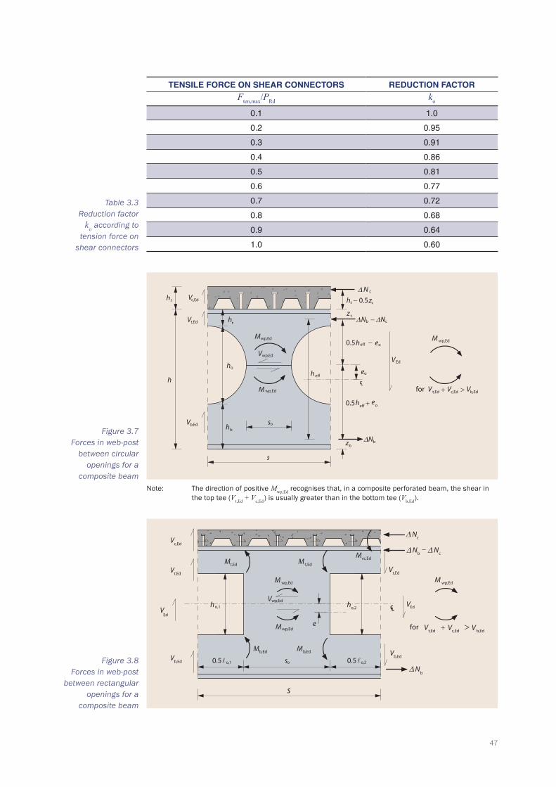
47
TeNSILe FOrCe ON SheAr CONNeCTOrS redUCTION FACTOr Ften,max/PRd ko
0.1 1.0
0.2 0.95
0.3 0.91
0.4 0.86
0.5 0.81
0.6 0.77
0.7 0.72
0.8 0.68
0.9 0.64
1.0 0.60
Table 3.3 Reduction factor
ko according to tension force on
shear connectors
Figure 3.8 Forces in web-post
between rectangular openings for a
composite beam
Figure 3.7 Forces in web-post
between circular openings for a
composite beam
t
t
b
bb
o
s c,Ed
t,Ed
b,Ed
wp,Ed
wp,Ed
wp,Ed
eff o
o
Ed
t,Ed c,Ed
wp,Ed
b,Ed
c
o
eff
eff
V
V
V
M
V
M
∆ cN
s − 0.5z
z∆ −∆ cbN N
∆N
V
M
for V + >V V
h
h
−
+
e
e
h
h
h
h
h
s
h
s
h
e
z
0.5
0.5
o
℄
o
c,Ed
t,Ed
Ed
wp,Ed
wp,Ed
wp,Ed
� � b,Ed
Ed
wp,Ed
vc,Ed
o,1 o,2
b,Ed b,Ed
o,2o,1
t,Edt,Ed
b,Ed
∆b
t,Ed
∆ −b ∆ c
∆ c
t,Ed c,Ed b,Ed
V
VV
M
V
V
V
M M
M
M
M
M
M
h h
V
N
V
N N
N
for V V V+ >
0.5 0.5 s
s
e
℄
Note: The direction of positive Mwp,Ed recognises that, in a composite perforated beam, the shear in the top tee (Vt,Ed + Vc,Ed ) is usually greater than in the bottom tee (Vb,Ed ).
48
UNSTIFFeNed OPeNINgS
The design forces for circular and rectangular openings are shown in Figure 3.7 and Figure 3.8. Equilibrium of the top and bottom Tees may be evaluated separately. The web-post horizontal shear is equal to the increase in tension in the bottom Tee between the centrelines of the adjacent openings.
3.5.1 Design longitudinal shear force in web-post
The design value of the longitudinal shear force, Vwp,Ed acting on the web-post may be determined from the consideration of the build up of tension forces in the bottom Tee.
As a first approximation, assume that there is sufficient shear connection to develop a force in the slab equal to the incremental force in the bottom Tee between the openings. The longitudinal shear force acting on the web-post is then given by:
Vwp,Ed V s
h z h hEd
eff t s c+ + −( )0 5.= (29)
where:VEd is the design value of the average of the shear forces at the centrelines of
adjacent openingss is the centre-to-centre spacing of the openingsheff is the effective depth of the beam between the centroids of the Tees (which
may conservatively be taken as the depth between their elastic neutral axes)zt is the depth of the centroid of the top Tee from the outer edge of the flange
(which may conservatively be taken as the elastic neutral axis position).
hc and hs are as previously defined.
The incremental compression force that can be mobilised in the slab due to the resistance of the shear connectors between openings is given by:
∆Ncs,Rd = nsc,sPRd (30)
where:nsc,s is the number of shear connectors between the centrelines of adjacent openingsPRd is the design resistance of a shear connector used with profiled sheeting
(i.e. PRd as given in Section 1.6 multiplied by kt or k
as given in Section 1.6.2).
If there is insufficient shear connection between the openings, the longitudinal shear force developed in the web-post is increased, and becomes:
Vwp,Ed V s N z h h
hEd t s c
eff
.− + −( )∆ cs,Rd 0 5= (31)
The larger of the values given by expressions (29) and (31) should be used.
49
3.5.2 Design compression force in web-post
Compression in the web-post (i.e. forces generally in a vertical direction) potentially leads to web-post buckling. This is a complex phenomenon which is discussed in Section 3.5.6. For verification of adequacy against buckling in the design model, it is necessary to distinguish between closely spaced openings, where the compression force is resisted by the full width of the end post, and widely spaced openings, where forces are resisted by effective widths of web adjacent to each of the openings.
The transition from widely spaced to closely spaced openings may be taken to occur at an edge-to-edge spacing equal to the opening length, corresponding to so = ho for circular openings and so = o for rectangular openings, where ho and o are the depth and length of the openings respectively. This transition is not exact but is used in order to simplify the analysis.
Design compression force for widely spaced openings
For widely spaced or discrete openings, web-post buckling is independent of the spacing of the openings. In this case, it is considered that a compression force acts at the edge of the opening over an effective width of ho/2. The magnitude of the compressive force may be taken as equal to the larger of the vertical shear forces in the top and bottom Tees. The use of the larger of the shear forces in the Tees takes account of any asymmetry in the opening position. The compressive force in the post at the edge of the opening is thus given by:
Nwp,Ed = VT,Ed (32)
where:VT,Ed is the larger of the shear forces in the two Tees (composite top Tee and
steel bottom Tee).
Design compression force for closely spaced openings
For closely spaced openings, the longitudinal shear force on the web-post Vwp,Ed is used to determine the design compression force on the web-post, rather than the vertical shear force, as in expression (32). This takes account of the higher forces acting in the web-post between the openings. For openings placed centrally in the beam depth, the compression stress acting on the web-post is taken as equal to the longitudinal shear stress acting on the web-post. The compression force acting on the web-post is thus given by:
Nwp,Ed = Vwp,Ed+ |Mwp,Ed|/(ho/2) (33)
where:Vwp,Ed is given by expressions (29) or (31)Mwp,Ed is the value of the web-post moment at the mid-height of the opening.
50
UNSTIFFeNed OPeNINgS
3.5.3 Design moment in web-post
The web-post is subject to bending as a result of Vierendeel bending action. When the shear forces resisted by the Tee sections above and below the opening are equal (which is the case for a symmetric steel beam with central openings), there is zero moment at the mid-height of the web-post. Equal and opposite moments, equal to Vwp,Ed ho/2, act on the top and bottom of the web-post. When the shear forces are not equal, an additional moment Mwp,Ed acts at mid-height of the web-post, given by:
Mwp,Ed = (Vt,Ed + Vc,Ed - Vb,Ed) s/2 + Vwp,Ed eo - ∆Ncs (zt + hs - 0.5hc)/2 (34)
where:VEd is the design value of the shear force acting mid-way between the
centrelines of adjacent openingsVc,Ed is the design value of the shear force in the concrete slab, which may be
taken as Vc,Rd (see Section 3.3.2)Vb,Ed is the design value of the shear force in the bottom TeeVt,Ed is the design value of the shear force in the top TeeVwp,Ed is the design value of the longitudinal shear force acting on the web-post
(which may be taken to be Vwp,Ed = ∆Nb,Ed)∆Nb,Ed is the increase in tension force in the bottom Tee between the centrelines of
the adjacent openingseo is the eccentricity of the centreline of the opening measured from mid-
height of the beam (taken as positive when the centreline of the opening is above the mid-height of the beam)
∆Ncs is the incremental compression force developed by the shear connectors over a length, s between adjacent openings. The value may be taken as ∆Ncs,Rd (see expression (30)).
s, zt hs, and hc are as previously defined.
The web-post moment will increase with asymmetry of the cross section (see Section 4). Any distribution of shear force between the Tees that satisfies equilibrium may be assumed, such that the value of Mwp,Ed is minimized.
From equilibrium of the forces, the shear force in the top Tee is given by: Vt,Ed = VEd − Vc,Rd − Vb,Ed, and thus:
Mwp,Ed = (VEd - 2Vb,Ed) s/2 + Vwp,Ed eo - ∆Ncs (zt + hs – 0.5hc )/2 (35)
Generally, for low values of design shear force, the moment in the web-post may be ignored.
If the height of adjacent openings differs or one of the openings is stiffened and the other unstiffened, then the distribution of shear between the top and bottom Tees may be different for each opening. In such cases, the mean of the values for the two openings should be used in the above expressions.
51
3.5.4 Shear resistance of web-post
The design longitudinal shear resistance of the web-post may be taken as:
Vwp,Ed s t fo w y
M0
( ) 3γ
= (36)
where:so is the edge-to-edge spacing of the openings (s - o)tw is thickness of the web.
Tests have shown that this resistance may be developed in the web-post, despite the complex stress state that exists locally in the web.
3.5.5 Buckling resistance of web-post
Buckling of the web-post is a complex phenomenon and is dependent on:
▪ shape of the opening, i.e. circular or rectangular; ▪ slenderness of the web at the opening; ▪ asymmetry of opening position in the beam depth.
Design model for web-post buckling
A simple compression field model has been developed from an approach presented in SCI Publication P100 [26] and uses an equivalent strut with a buckling length defined by the opening dimensions and spacing. It has been calibrated against FEA results and is conservative relative to the FEA [27]. It has been calibrated over the range ho ≥ so ≥ 0.3ho and has been extended to consider openings placed asymmetrically in the depth of the beam. In this case in-plane moments are generated in the web-post.
Basis of the strut model
The design model is based on the following assumptions:
▪ A compression stress acts in the web-post, taken as equal in magnitude to the longitudinal shear stress acting on the web-post.
▪ Buckling occurs over an effective length of web, which depends on the spacing of the openings.
▪ An additional in-plane bending stress may act on the web-post (for highly asymmetric opening positions, see Section 4).
Three design cases may be considered:
▪ Widely spaced openings. ▪ Closely spaced openings. ▪ Asymmetrically placed openings in the beam depth.
The analysis for rectangular and circular openings differs only in the buckling length w of the web-post in compression.

52
UNSTIFFeNed OPeNINgS
o
o
o
a. Widely spaced rectangular openings
o
o o
o
� = effective web length
�wwp,EdV
wp,EdN
wp,EdN
wp,EdN
wp,EdN
wp,EdN
wp,EdN
�
�
b. Closely spaced circular openings
o o
o
M
Mwp,Ed
wp,Ed
wp,Ed
wp,EdM
V
= h
s ho
VEd /2
VEd /2
w
w
VEd /2
VEd /2
o
s o < 0.5h o
c. Asymmetrically placed openings in beam depth
V
V
t
b
0.5h
0.5h
h
h
s
eh
0.7h
0.7h
= web-post moment
℄
Figure 3.9 Web-post
bending model for buckling analysis
53
These design cases are illustrated in Figure 3.9.
Buckling resistance for widely spaced openings
For widely spaced openings, a buckling length of w = ho is appropriate for rectangular openings and w = 0.7ho for circular and elongated circular openings.
For the determination of the reduction factor on buckling resistance χ, the non-dimensional slenderness of the web-post λ may be expressed for these buckling lengths as:
a. For circular openings and elongated circular openings:
λ λ
=2 5 1o
1
. htw
(37)
b. For rectangular openings:
λ λ
=3 5 1o
1
. htw
(38)
where λ1 is defined in BS EN 1993-1-1, §6.3.1.3 as:
λ1 πEfy
= = 94 ε and ε 235 / fy( )=
The design buckling resistance of the web-post Nwp,Rd is determined from BS EN 1993-1-1, §6.3.1. Based on test evidence, buckling curve b may be used for rolled sections; buckling curve c sould be used for beams fabricated from plates. The buckling resistance of the web post is therefore:
Nwp,Rd 0 5. h t fo w y
M1γ= χ (39)
The verification may be expressed as Nwp,Rd ≥ Nwp,Ed
Buckling resistance for closely spaced openings
For closely spaced openings, a buckling length of �w o o= +( )0 7 2 2. s h is appropriate for rectangular openings and �w o o= +( )0 5 2 2. s h for circular and elongated circular openings.
The non-dimensional slenderness of the web-post λ may then be expressed as:
a. For circular openings and elongated circular openings:
λ λ
=+1 75 12 2
1
. s ht
o o
w
(40)
b. For rectangular openings:
λ λ
=+2 5 12 2
1
. s ht
o o
w
(41)
where λ1 is as defined in BS EN 1993-1-1, §6.3.1.3 (see above).
54
UNSTIFFeNed OPeNINgS
The design buckling resistance of the web post, Nwp,Rd, is determined from buckling curve b in BS EN 1993-1-1, §6.3.1.2 for rolled sections and beams fabricated from rolled sections, or from buckling curve c for beams fabricated from plates. The buckling resistance of the web-post is given by:
Nwp,Rd s t fo w y
M1
χ= γ (42)
The verification may be expressed as Nwp,Rd ≥ Nwp,Ed.
Minimum opening width for web-post buckling
Web post buckling effects are small and can be ignored for widely spaced openings for the following conditions:
ho/tw ≤ 25 for circular openingsho/tw ≤ 20 for rectangular openings
(43)
3.5.6 Bending resistance of web-post
The design bending resistance of the web-post should be taken as its elastic value. For rectangular openings, and for circular openings at the mid-height of the opening, this is given by:
Mwp,Rd = s to w
2
6fy
M0γ (44)
For rectangular openings, the bending resistance of the web-post should be such that:
Mwp,Rd ≥ Vwp ho /2 + |Mwp,Ed| (45)
where: Vwp,Ed is given by expressions (29) or (31)Mwp,Ed is the value of the web-post moment at the mid-height of the opening.
Web-post bending resistance may control for closely spaced rectangular openings.
The design moment at the mid-height of the web-post does not modify its ability to resist shear at that section, provided the elastic bending resistance of the web-post is used.
For circular openings, web-post bending does not control the design of the web- post because the increasing width of the web-post from its mid-height increases its bending resistance.

55
3.6 Shear buckling adjacent to an isolated opening
As an alternative methodology for slender webs with isolated openings, the shear buckling resistance of a web may be modified to take account of an isolated opening. The shear buckling resistance of a slender unperforated web is given by BS EN 1993-1-1, §6.2.6(6) and BS EN 1993-1-5, §5. The shear buckling resistance of the web with isolated openings may be taken conservatively as:
Vw,o,Rd Vhhbw,Rd
o o
w
= −
0 9 1.
� (46)
where Vbw,Rd is the shear buckling resistance given by BS EN 1993-1-5, §5.2.
For a circular opening, o = ho in this formula.
It should be noted that this formula is based on inclined stress field action in the web, and is therefore only appropriate for isolated openings because of the complementary compression developed in the web. When the opening is at least 0.8 hw from the end of the beam (where hw is the clear depth between flanges) Vw,o,Rd may be taken as that for a rigid end-post, as defined in BS EN 1993-1-5, irrespective of the actual end-post width.
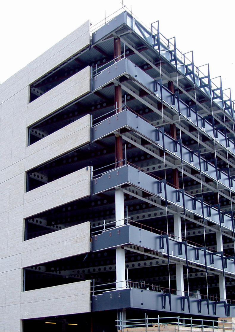
56
57
This Section presents expressions for the limiting value of vertical shear resistance of beams with closely spaced openings, dependent on web-post bending resistance and web-post buckling resistance.
4.1 Resistance governed by web-post bending
4.1.1 Resistance for circular openings
In the limit, the shear force in the bottom Tee reaches its maximum value due to Vierendeel bending and the moment in the web-post reaches its elastic bending resistance. By re-arranging the previous equilibrium equations, closed solutions can be established for the maximum vertical shear that can be resisted (i.e. when Mwp,Ed = Mwp,Rd).
For partial shear connection, when Vwp,Ed > ∆Ncs,Rd, the limiting value of design vertical shear resistance of the perforated beam is given by:
VRd = 2 4
1 20 5
M s Me h
Ns
z h he
wp,Rd b,NV, Rd o
o ff
cs,Rdt s c
/ //
.+
++ + −( )
� ∆ (47)
where:Mwp,Rd is the elastic bending resistance of the web-post at mid-height of the
opening, given by expression (44)MbT,NV,Rd is the bending resistance of the bottom Tee, reduced due to the effect of
axial tension (given by expression (20) or (23) depending on the section classification). Initially, no reduction for shear should be made, provided that the shear resisted by the bottom Tee does not exceed half its plastic shear resistance
∆Ncs,Rd is the incremental compression force that can be mobilised in the slab due to the resistance of the shear connectors between openings.
eo, hc, heff, hs, o, s and zt are all as previously defined.
For full shear connection, when Vwp,Ed ≤ ∆Ncs,Rd, the compression force in the web-post is taken as equal to Vwp,Ed, which leads to the following equation for limiting vertical shear resistance of the perforated beam:
VRd = 2 / 4 /0.5
2wp,Rd bT,NV,R d oeff s c
eff o
M s Mh h h
h e+
+ −[ ]+[ ]
� (48)
Limiting shear resistanCe for Beams with CLoseLy spaCeD openings
58
CLOSeLy SPACed OPeNINgS
The limiting value of VRd should be taken as the smaller of the values given by these two equations.
If the shear force VEd can be resisted by evaluating VRd with Mwp,Rd set to zero, then it follows that no web-post moment is required for equilibrium.
4.1.2 Resistance for rectangular openings
The behaviour of beams with closely spaced rectangular openings is different from that of circular openings because of the greater importance of Vierendeel bending and web-post bending.
In a composite beam with rectangular openings, high in plane moments are generated in the web-post in order to maintain equilibrium in the bottom Tee. The critical point for web-post moment generally becomes the top of the web-post due to the combined moment and longitudinal shear effects, which should satisfy the following limit for a rectangular opening:
Mwp,Rd ≥ Vwp,Ed ho/2 + |Mwp,Ed| (49)
where:Mwp,Rd is the elastic bending resistance of the web-post, given by expression (44)Mwp,Ed is the web-post moment at the mid-height of the opening.
By rearranging the previous equilibrium equations, it can be shown [27] that the shear resistance that can be developed between adjacent rectangular openings is as follows.
For partial shear connection, when Vwp,Ed > ∆Nc,s,Rd, the limiting value of design vertical shear resistance of the perforated beam is given by:
VRd = 2 4
1 20 5
M s Me h h
Ns
z h he
wp,Rd bT,NV,R d o
o o ff
cs,Rdt s c
/ //
.+
+ +( )+ + −
� ∆(( ) (50)
Where one of the adjacent openings is stiffened and the other unstiffened, MbT,NV,Rd may be taken as the mean value for the two bottom Tees.
For full shear connection, when Vwp,Ed ≤ ∆Nc,s,Rd, the limiting value of design shear resistance is given by:
VRd = 2 / 4 /0.5
2wp,Rd bT,N,Rd oeff s c
eff o o
M s Mh h hh e h
+ + −[ ]+ +[ ]
� (51)
The value of VRd should be taken as the smaller of the values given by these two expressions.

59
4.2 Resistance governed by web-post buckling
The same approach as above may be adopted to derive a closed solution for the vertical shear resistance of the perforated beam, limited by web-post buckling, as follows.
For partial shear connection:
VRd = N h s M
h hN
sz h h
e
wp,Rd o bT,NV,Rd o
o,eff ff
cs,Rdt s
/ //
.( ) +
++ + −
41
0 5� ∆
cc( ) (52)
For full shear connection, the compression force ∆Nc,Ed is taken as equal to Vwp,Ed, which leads to the following equation for limiting vertical shear resistance:
VRd = N h s Mh h h
h h ee
e
wp,Rd o bT,NV,Rd off s c
ff o o
/ /.
( ) + + −[ ]+ +[ ]
40 5
2� (53)
where:Nwp,Rd is the web-post buckling resistance, as defined in Section 3.5.6Mb,NV,Rd is the bending resistance of the bottom Tee, reduced due to the effect of
axial tension and shear as appropriate (given by expression (20) or (23) depending on the section classification).
The limiting value of VRd should be taken as the smaller of the values given by these two expressions.
As noted above, if one opening is stiffened and one unstiffened, the average value of MbT,NV,Rd may be used.
The web-post buckling verification for eccentric openings is the same for both circular and rectangular openings, using an appropriate value of Nwp,Rd. No web-post buckling verification is required when the spacing of the openings satisfies the limits for widely spaced openings.
4.3 Verification of shear resistance
The value of the shear resistance VRd should be taken as the smaller of the limiting values for web-post bending and web-post buckling given by Sections 4.1 and 4.2 but not greater than (Vpl,Rd + Vc,Rd ) for the perforated section (see Section 3.3). It is generally found that web-post bending will control for rectangular openings, whereas web-post buckling will control for circular openings.
For verification of shear resistance, the value of VRd should be at least equal to the shear force midway between the centrelines of adjacent openings, VEd.

60
CLOSeLy SPACed OPeNINgS
∆
∆
a. Forces at an elongated opening
b. Moments required to achieve equilibrium
�eff
c,Ed
t,Ed
b,Ed
Ed
vt,Ed
vb,Ed
wp,Ed wp,Ed
vt,Ed
Ed
wp,Ed
t,Ed c,Ed b,Ed
∆ c vc,Ed
vb,Ed
∆ b b∆ b
M
V
V
V
V
V
M
M
M
M
M
N
M
M
N N
e
∆ c23
3 N
NN
c
for V V V+ >
= Mvt,Ed M+ vb,Ed
= M M+ vt,Edvc,Ed M+ vb,EdAppliedmoment
Moment due todirect tension -compression in tees
Vierendeelmoment
Vierendeelmoment
Figure 4.1 Forces in web-post at an elongated opening
4.4 Eccentricity effects for elongated openings
Elongated openings may be created by removing the web-post between adjacent circular openings. The same approach as described for closely spaced openings applies to elongated openings except that the web-post moment developed due to asymmetry effects will increase. This behaviour is illustrated in Figure 4.1.
The previous expressions may be modified as follows: the value of s should be taken as the distance between the centrelines of the circular and elongated openings (which is often twice the regular spacing, when a web-post has been removed); the effective length of the opening is given by e = o − 0.55ho. It follows that the maximum value of VRd in the above expressions is considerably reduced, unless Mb,N,Rd is increased by the use of horizontal stiffeners above and below the elongated opening.

61

62
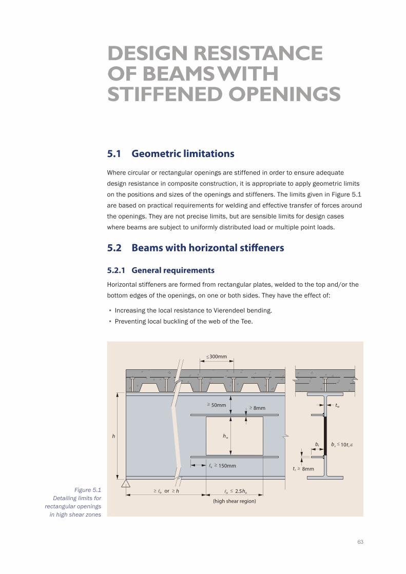
63
5.1 Geometric limitations
Where circular or rectangular openings are stiffened in order to ensure adequate design resistance in composite construction, it is appropriate to apply geometric limits on the positions and sizes of the openings and stiffeners. The limits given in Figure 5.1 are based on practical requirements for welding and effective transfer of forces around the openings. They are not precise limits, but are sensible limits for design cases where beams are subject to uniformly distributed load or multiple point loads.
5.2 Beams with horizontal stiffeners
5.2.1 General requirements
Horizontal stiffeners are formed from rectangular plates, welded to the top and/or the bottom edges of the openings, on one or both sides. They have the effect of:
▪ Increasing the local resistance to Vierendeel bending. ▪ Preventing local buckling of the web of the Tee.
Design resistanCe of Beams with stiffeneD openings
o
r
w
�o o�o
r
(high shear region)
8mm50mm
300mm
h
t
b
h
or h 2.5h
8mmt 150mm�v
r r εb 10t
Figure 5.1 Detailing limits for
rectangular openings in high shear zones

64
STIFFeNed OPeNINgS
In choosing the size and position of horizontal stiffeners, consideration must be given to the practicality of connecting the stiffeners to the beam web (i.e. there must be sufficient access to make the welds). Where openings are close to the section flanges, partial penetration butt welds from one side of the stiffener may be the only solution.
The outstand/thickness ratio of the stiffeners should not exceed the limits for a Class 3 (semi-compact) section. If the beam is designed as a Class 1 or 2 section, then any part of the outstand in excess of the Class 2 limit must be considered as ineffective. In the region of the opening, the web is considered to be Class 2 when stiffened.
The maximum size of stiffener is generally controlled by the ability of the web to resist the local anchorage forces, which are transferred by the weld between the stiffener and the web at the ends of the opening. A suitable anchorage length is required in order to develop the axial resistance of the stiffener.
Stiffeners welded on one side of the web can be more efficient from a fabrication point of view but where single-sided stiffeners are used it is necessary to ensure that the web is sufficiently strong in transverse bending that the eccentric forces can be transferred from the stiffener to the web.
5.2.2 Stiffener size and anchorage length
A practical upper bound to the stiffener area is Ar ≤ 0.5hotw. This will ensure that the adjacent web is strong enough to resist the force transferred from the stiffener.
In practice, horizontal reinforcement (stiffeners) in excess of 200 mm wide and 20 mm thick are not recommended. A minimum width of 80 mm or o/10 is recommended.
In selecting the size of stiffener, the following rule may be used for stiffeners on both sides of the web:
tt
r
w
bv
r
.≤
1 2
2�
(54)
where: v is the anchorage length of the stiffenertr is the thickness of the stiffenertw is the thickness of the webbr is the width of the stiffener.
Stiffeners should preferably be attached by fillet welds to both sides of the stiffener (although butt welds might be unavoidable in some cases, as noted above). The throat thickness of the fillet weld should be equal to at least half the thickness of the stiffener. The minimum offset distance from the edge of the opening should be at least 8 mm, to allow for at least a 5 mm leg length fillet weld.
The anchorage length v of the stiffener beyond each end of the opening should generally be at least 0.25o and should satisfy the following criteria:
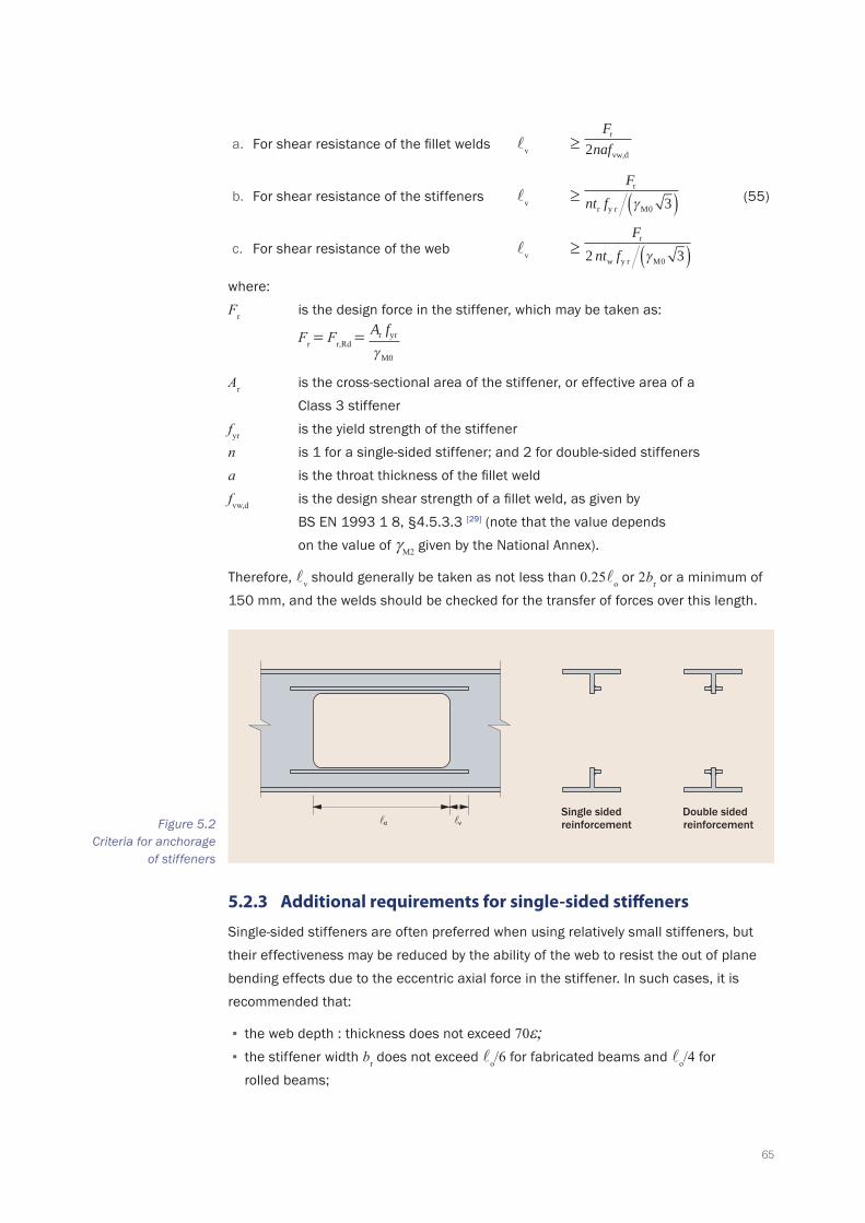
65
a. For shear resistance of the fillet welds v ≥ F
nafr
2 vw,d
b. For shear resistance of the stiffeners v ≥ F
nt fr
r y r M0γ 3( ) (55)
c. For shear resistance of the web v ≥ F
nt fw
r
y2 3r M0γ( )where:Fr is the design force in the stiffener, which may be taken as:
Fr = Fr,Rd = A fr yr
M0γ
Ar is the cross-sectional area of the stiffener, or effective area of a Class 3 stiffener
fyr is the yield strength of the stiffenern is 1 for a single-sided stiffener; and 2 for double-sided stiffenersa is the throat thickness of the fillet weldfvw,d is the design shear strength of a fillet weld, as given by
BS EN 1993 1 8, §4.5.3.3 [29] (note that the value depends on the value of γM2 given by the National Annex).
Therefore, v should generally be taken as not less than 0.25o or 2br or a minimum of 150 mm, and the welds should be checked for the transfer of forces over this length.
o� �vDouble sidedreinforcement
Single sidedreinforcementFigure 5.2
Criteria for anchorage of stiffeners
5.2.3 Additional requirements for single-sided stiffeners
Single-sided stiffeners are often preferred when using relatively small stiffeners, but their effectiveness may be reduced by the ability of the web to resist the out of plane bending effects due to the eccentric axial force in the stiffener. In such cases, it is recommended that:
▪ the web depth : thickness does not exceed 70ε; ▪ the stiffener width br does not exceed o/6 for fabricated beams and o/4 for rolled beams;
66
STIFFeNed OPeNINgS
▪ the stiffener thickness tr does not exceed tw (see below); ▪ the anchorage length v should be taken as the smaller of 2br and the distance to the edge of the adjacent opening, and should satisfy the limits in expression (55).
The thickness of the stiffener should satisfy the following limit:
tt
r
w
bv
r
.≤
0 96
2� but ≤ 1.0 for stiffeners on one side of the beam (56)
5.2.4 Bending resistance of beams with horizontal stiffeners
Vierendeel bending
Plastic resistance of Tees
The expressions for plastic bending resistance of the Tee given in Section 3.4.4 are modified when longitudinal stiffeners are used, as follows:
Mpl,Rd A f h t z
A ft z z tw,T y
M0
wtf pl
f y
M0f pl pl f= + −
+ − +(
γ γ20 5 2. ))
+ + − −( )A ft h e zr y
M0f w,T r plγ
(57)
where:zpl is the distance between the plastic neutral axis and the extreme fibre of the
steel flange given by: zpl = (Af + Aw,T + Ar)/(2bf) for Ar ≤ Af – Aw,T
Aw,T is the cross-sectional area of web of the Tee = hw,T tw,eff
Af is the cross-sectional area of the flangebf is the breadth of the flangehw,T is the depth of web of the Tee, excluding the flange (= hwb or hwt as appropriate)tf is the thickness of the flangeAr is the cross-sectional area of horizontal stiffenerser is the offset distance of centre of stiffener from tip of web.
Elastic resistance of Tees
The expressions for elastic bending resistance of the Tee given in Section 3.4.5 are modified when there are longitudinal stiffeners, as follows:
Mel,Rd A f h t z A f z t A f hw,T y w,T f el f y el f=
+ − + − +( . ) ( . ) (r y,r w,0 5 0 52 2TT l
w,T f el M0
− + −
+ −
e t zh t z
r f e )( )
2
γ (58)
where:zel is the distance between the elastic neutral axis and the extreme fibre of the
steel flange given by:
zel = A h t t A A h e t
A Arw,T w,T f f f w,T r f
f w,T
( . ) .( )
0 5 0 5+ + + − +( )+
(59)
67
5.2.5 Effect of axial force on bending resistance
For a stiffened bottom Tee, a linear reduction in bending resistance with axial tension is conservatively used because of the influence of the stiffener area [23], as follows:
Mpl,N,Rd = Mpl,Rd(1 – NEd/Npl,Rd) (60)
This moment axial force interaction formula is conservative for small stiffener areas, where the interaction tends to be quadratic in form.
5.2.6 Shear resistance of Tees
The horizontal stiffeners may conservatively be ignored in calculation of the shear resistance of the Tees. As a consequence of this, the shear area of the Tees may be calculated in accordance with Section 3.3.1 and, where the Tee is subject to high shear, the bending resistance should be reduced as shown in Section 3.4.3.
5.2.7 Effect of long openings
At long stiffened openings, a reduction factor is applied to the local Vierendeel bending resistance due to composite action to allow for the flexibility of the opening. For horizontally stiffened openings, this reduction factor, ko is given by:
ko = 135
−
�o
th (61)
where:ht is the depth of the top Tee;ko may be taken as 1.0 for o ≤ 5ht for stiffened openings.
An alternative, more accurate (but complex), approach is to consider the effect of tensile forces in the shear connectors on the composite component of Vierendeel bending resistance, Mvc,Rd, as presented in Section 3.4.6.
5.3 Vertical stiffeners
Vertical stiffeners are not generally required in beams with Class 1 or Class 2 sections, but may be required for Class 4 sections. However, vertical stiffeners may be needed at heavy concentrated point loads and at secondary beam connections. This generalisation applies also to perforated beams. When provided, vertical stiffeners should generally be full depth, unless the unstiffened part of the web is sufficient to prevent local buckling.

68
STIFFeNed OPeNINgS
5.4 Ring stiffeners
5.4.1 Effect of ring stiffeners on web-post behaviour
Ring stiffeners welded around the inside of circular openings have the effect of suppressing web-post buckling (for Class 3 webs). Two cases may be considered:
Adjacent ring stiffened openings
Based on finite element analysis (FEA) of typical cases, it is considered that the ring stiffeners reduce the slenderness of the web-post by a factor of 0.7 by preventing any buckling along the edge of the opening and thus the value of λ given by expression (37) is multiplied by a factor of 0.7. Openings with a diameter less than 40twε, may be considered as fully restrained against web-post buckling if ring stiffeners are provided.
Ring stiffened opening on one side of a web-post
Based on FEA, it is considered that the ring stiffeners on one side of the web-post have a partial effect on web-post buckling. It is considered that the buckling length of the strut is reduced by a factor of 0.85 for s/ho ≤ 1.5 and thus the value of λ given by expression (40) is multiplied by a 0.85. For wider web-posts with s/ho > 1.5, no effect of the adjacent ring stiffener should be taken into account.

69

70

71
The serviceability limits likely to be of relevance to the design of composite beams are those concerning control of deflections, control of cracking in the slab, and minimising of perceptible floor vibrations. In the case of beams with large web openings, the principal influences for design at the Serviceability Limit State (SLS) are:
▪ Additional deflection due to the loss of flexural stiffness at the openings. ▪ Additional deflection due to Vierendeel bending effects at large openings (shear deflection).
▪ Reduction in overall stiffness (leading to greater dynamic response).
6.1 Calculation of additional deflections
6.1.1 Use of elastic section properties
Serviceability performance is established using elastic properties, taking account of the loss of web on deflections. For pure bending, the elastic stiffness is defined as in Figure 6.1. In tests on composite beams with large openings, little deviation from elastic behaviour in the load-deflection response of the beams occurs until close to failure, and therefore local yielding is not important as regards overall serviceability behaviour. Furthermore, for beams with stiffened webs, the loss of stiffness of the perforated section is reduced.
BehaViour at serViCeaBiLity Limit state
a. Cross-section at opening
b. Elastic stresses c. Equivalent elastic stress blocks
o
eff
h
b
h
0.5h
Figure 6.1 Elastic properties of a
perforated beam
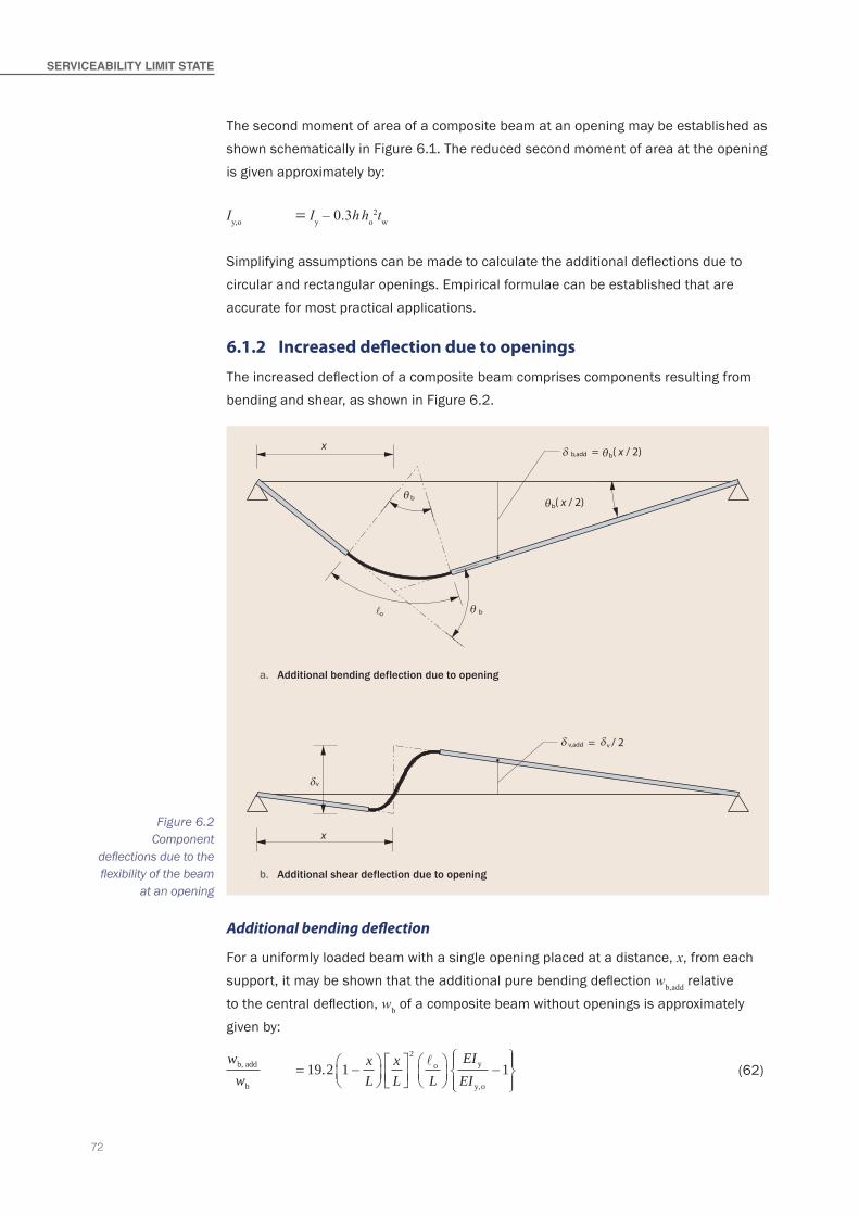
72
ServICeABILITy LIMIT STATe
The second moment of area of a composite beam at an opening may be established as shown schematically in Figure 6.1. The reduced second moment of area at the opening is given approximately by:
Iy,o = Iy – 0.3h ho2tw
Simplifying assumptions can be made to calculate the additional deflections due to circular and rectangular openings. Empirical formulae can be established that are accurate for most practical applications.
6.1.2 Increased deflection due to openings
The increased deflection of a composite beam comprises components resulting from bending and shear, as shown in Figure 6.2.
b
bo
a. Additional bending deflection due to opening
b( x / 2)
b. Additional shear deflection due to opening
v
v,add v / 2=
=b,add
δδ
δ
θ
θθ
b( x / 2)θδx
x
�
Figure 6.2 Component
deflections due to the flexibility of the beam
at an opening
Additional bending deflection
For a uniformly loaded beam with a single opening placed at a distance, x, from each support, it may be shown that the additional pure bending deflection wb,add relative to the central deflection, wb of a composite beam without openings is approximately given by:
wwb,
b
add xL
xL L
EIEI
o y
y,o
.= −
−
19 2 1 1
2 �
(62)
73
where:Iy is the second moment of area of the full composite sectionIy,o is the second moment of area of the composite section at an opening.
wb F L
EI=
5384
3d,ser
where:Fd,ser is the design value of the total load on the beam at SLSL is the span of the beam.
For a beam subject to a central point load, the additional deflection is given by:
wwb,
b
add xL
xL L
EIEI
o y
y,o
.= −
−
12 0 1 1
2 �
(63)
and the central deflection is given by:
wb F L
EIsd=
3
48 y
Additional shear deflection
The additional shear deflection wv,add for a single opening, expressed as relative to the pure bending deflection, is given by:
wwv,add
b
xL L
EIEI
o
T
. y
y,
= −
1 6 1 2 3� for a uniformly distributed load
wwv,add
b
xL L
EIEI
o
T
. y
y,
= −
1 0 1 2 3� for a central point load
(64)
where Iy,T is the second moment of area of a Tee, averaged above or below the opening. This ignores the significant contribution of the concrete in local composite action, which may be included in a more refined analysis. The composite stiffness may be expected to double the effective stiffness of the Tee, EIT. This shear component may be significant for long openings.
The total additional deflection is therefore wb,add + wv,add.
6.2 Approximate method
6.2.1 Single openings in a composite beam
As a more simple alternative, the following approximate empirical formula is established from an analysis of the additional deflection of a composite beam, which is based on the pure bending deflection due to the loss of stiffness at the opening. The approximation also allows for the influence of the deflection in the high shear regions by the term (1 - x/L), where x is the distance from the nearer support to the centreline of the
74
ServICeABILITy LIMIT STATe
opening. As a good approximation, the additional deflection due to an opening, wadd, may be expressed as relative to that of the unperforated composite beam in pure bending, wb as follows:
ww
add
b
= ko �o o
Lhh
xL
−
1 for x ≤ 0.5L
ww
add
b
= ko � o o
Lhh
xL
for x > 0.5L
(65)
where the coefficient, ko, is given by:ko = 1.0 for longitudinally stiffened openingsko = 1.5 for unstiffened openings
and:o is the effective length of opening ( = 0.45ho for circular openings when
calculating deflections)wb is the bending deflection of unperforated composite beam.
The formula for additional deflection becomes more conservative for shorter openings, where Vierendeel deflections are less.
6.2.2 Additional deflection due to multiple openings
For multiple regular sized openings, the additional deflections may be taken as:
ww
add
b
= 0 7. n kL
hh
o oo o�
(66)
where no is the number of regular openings along the beam. The factor of 0.7 represents the combined effect of the distribution of moment and shear along the beam.
Typically, for a cellular beam (where o = 0.45ho) the above expression reduces to:
ww
add
b
= 0 472
. n hh
hL
oo
(67)
The additional deflection due to the openings in a cellular beam is typically 12 to 15% of that of an unperforated beam of the same depth.

75

76

77
7.1 Highly asymmetric openings
Highly asymmetric positions of openings may be necessary if the opening has to be close to one flange, as illustrated in Figure 7.1. In this case, it is recommended that a horizontal stiffener is introduced in order that the local bending resistance of the remaining section is increased. The Vierendeel bending resistance is then entirely dependent on the remaining Tee.
In such cases, the openings should be placed sufficiently far apart that web-post bending is not critical (see Section 4). This is satisfied when the edge-to-edge spacing of the openings exceeds twice the depth of the larger opening.
speCiaL Cases
V
N
VM
M
o�
h
b,Ed
o
EdEd
cN Nb,Ed + Nc
h
vt,Ed
vt,Ed
b,EdN= cN =
N c
N b,Ed
h
20 mmFigure 7.1
Highly asymmetric rectangular opening
7.2 End-posts
The end-post width defines the distance of the edge of the first opening from the end of the beam. The longitudinal shear and buckling resistance of the end-post depends on the type of connection that is used and on notching of the ends of the beam.
Full depth end-plates are preferred for primary beams supporting high shear forces and for connections to columns. In this case, the end-plate transfers shear forces smoothly
78
SPeCIAL CASeS
into the web and partially restrains the web against buckling. Therefore, the stability of the end-post is probably greater than the first web-post between openings.
Conversely, fin plates, web cleats and partial depth end plates offer much less restraint to the end-post. Furthermore, secondary beams are often notched at their top flange, which will increase the effective length of the end-post, certainly for non-composite beams.
It is not possible to give definitive guidance on the design of end-posts in composite beams with web openings, depending on the connection type. It is recommended that the minimum width of the end-post is not less than 0.5ho, for a circular opening where ho is the diameter of the first opening and, for a rectangular opening, not less than its length, o.
For cellular beams with multiple openings, a conservative approach is to ignore composite action at the first opening, which will increase the longitudinal shear forces used in the design checks for first web-post. Also, the final opening can be half-filled to increase the width of the end-post. As noted above, a full depth end plate connection will stiffen the end-post locally.
7.3 Notched beams
Large notches are sometimes cut in the beam adjacent to a column to allow the passage of services, etc. The notch is formed by cutting away the bottom flange and web adjacent to the support, as illustrated in Figure 7.2. Generally a horizontal stiffener is provided to increase the local bending resistance of the reduced section.
For analysis purposes, there is a similarity between the local bending at the notch and the Vierendeel bending around openings; here, the Vierendeel bending resistance reduces due to tension arising from local composite action between the slab and the top Tee. The requirement may be expressed as:
VEdo ≤ MtT,NV,Rd + Mvc,Rd (68)
where: MtT,NV,Rd is the bending resistance of the top Tee, reduced for axial compression
and for shearMvc,Rd is the local composite Vierendeel moment resistance, as defined
in Section 3.4.6.
Recommended dimensional limits for notched beams are shown in Figure 7.2 in order to avoid local deformation at the notch.
Also, it is recommended that the first adjacent opening is located at a distance not less than the notch length from the end of the notch.
79
Nc
Nc
VEdVEd
�o
h
h
Service zone
0.5
h2≤Figure 7.2
Notched beam showing proposed dimensional limits

80
81
[1] LAWSON, R. M. Design of openings in the webs of composite beams (P068), SCI/CIRIA, 1987
[2] LAWSON, R. M., CHUNG, K. F. and PRICE, A. M. Tests on composite beams with large web openings to justify existing design methods,The Structural Engineer, Vol 70, No.1, 7 January 1992
[3] ENV 1993-1-1:1992/A2:1998 Eurocode 3: Part 1.1 – Amendment A2, CEN, 1998
[4] DARWIN, D. Design of steel and composite beams with web openings. Steel Design Guide Series 2, American Institute of Steel Construction, 1990
[5] MCKENNA, R. D. and LAWSON, R. M. Design of steel framed buildings for service integration (P166), The Steel Construction Institute, 1997
[6] BS EN 1993-1-1:2005 Eurocode 3: Design of steel structures. Part 1.1: General rules and rules for buildings, BSI
[7] BS EN 1994-1-1:2004 Eurocode 4: Design of steel and concrete composite structures. Part 1.1: General rules and rules for buildings, BSI
[8] BS 5950 1:2000 Structural use of steelwork in building. Part 1: Code of practice for design. Rolled and welded sections, BSI
[9] BS 5950 3-1:1990 Structural use of steelwork in building. Part 3.1: Design in composite construction. Code of practice for design of simple and continuous composite beams, BSI
[10] BRETTLE, M. E. Steel building design: Introduction to the Eurocodes (P361), The Steel Construction Institute, 2009
[11] BS EN 1990:2002 Eurocode. Basis of structural design, BSI
[12] BS EN 1991-1-1:2002 Eurocode 1. Actions on structures. Part 1.1: General actions. Densities, self-weight, imposed loads for buildings, BSI
[13] BS EN 1991-1-6:2005 Eurocode 1 Actions on structures. Part 1.6: General actions. Actions during execution, BSI
referenCes
[14] BS EN 1992-1-1:2004 Eurocode 2: Design of concrete structures. Part 1.1: General rules and rules for buildings, BSI
[15] BS EN 1993-1-2:2005 Eurocode 3. Design of steel structures. Part 1.2: General rules. Structural fire design, BSI
[16] BS EN 1994-1-2:2005 Eurocode 4. Design of composite steel and concrete structures. Part 1.2: General rules. Structural fire design, BSI
[17] JOHNSON, R. P. and ANDERSON, D. Designers Guide to EN 1994-1-1 Eurocode 4: Design of composite steel and concrete structures. Part 1.1: General rules and rules for buildings, Thomas Telford, 2005
[18] BS EN 10025:2004 Hot-rolled products of structural steels. Part 2: Technical delivery conditions for non-alloy structural steels, BSI
[19] BS EN 10346:2009 Continuously hot-dip coated steel flat products. Technical delivery conditions, BSI
[20] BS EN 1993-1-3:2006 Eurocode 3. Design of steel structures. Part 1.3: General rules. Supplementary rules for cold-formed members and sheeting, BSI
[21] JOHNSON R. P. and MOLENSTRA N. Partial shear connection in composite beams for buildings. Proceedings of Institution of Civil Engineers, Part 2, Vol 91, Dec 1991, p679-70
[22] ARIBERT, J. M. Design of composite beams with partial shear connection (in French). Symposium on Mixed Structures, including New Materials, Brussels, IABSE. Zurich Report 60, 1990, p215-220
[23] Large web openings for service integration in composite floors. Final Report for ECSC Research Contract 7210-PR-315, 2003 European Commission, EUR 21345, ISBN: 92-79-01723-3, EU Bookshop (http://bookshop.europa.eu), Catalogue Number: KI-NA-21345-EN-C, 2006
[24] SMITH, A. L., HICKS, S. J. and DEVINE, P. J. Design of floors for vibration: A new approach (P354), The Steel Construction Institute, 2009
82
reFereNCeS
[25] REDWOOD, R. G. Design of beams with web holes, Canadian Steel Industries Construction Council, 1973
[26] WARD, J. K. Design of composite and non-composite cellular beams (P100), The Steel Construction Institute, 1990
[27] LAWSON, R. M., LIM, J., HICKS, S. J. and SIMMS, W. I. Design of composite asymmetric cellular beams and beams with large web openings, Journal of Constructional Steel Research, Vol. 62, No.6, June 2006, pp.614-629.
[28] JOHNSON, R. P. and BUCKBY, R. J. Composite Structures of Steel and Concrete, Volume 2: Bridges, Second Edition, Collins, London, 1986
[29] BS EN 1993-1-8:2005 Eurocode 3. Design of steel structures. Part 1.8: Design of joints, BSI
[30] BS EN 1993-1-5:2006 Eurocode 3. Design of steel structures. Part 1.5: Plated structural elements, BSI

83
CreDits
xii Broadgate Tower, London
1 London School of Economics renovation, London
3 Web opening test, Warwick University
2 Longacre, London
56 Kings Place, London
2 Belgrave House, London
80 Bishops Square, London
3 Large web opening
2 Commerzbank, Frankfurt
Cover Detail of openings in beamBroadgate Tower, London

8484

85
appenDiX a
The worked example is carried out for a composite beam with circular and rectangular openings to illustrate the use of the design method presented in this publication.
Design example for composite beam with web openings
1 sCoPe 87
2 dimensions&ProPerties 88
2.1 Generaldimensions 88
2.2 Openings 88
2.3 Sectionpropertiesofbeam 88
2.4 Materialproperties 88
3 aCtions 89
3.1 Constructionstage 89
3.2 Compositestage 89
3.3 Partialfactorsforactions 89
3.4 Designvaluesofcombinedactions 89
3.5 Designbendingmoments&shears 90
4 sHearConneCtion 90
4.1 Shearconnectorresistance 90
4.2 Numberofshearconnectors 91
4.3 Detailingofshearconnection 92
5 BendinGresistanCeatmid-sPan(ComPositestaGe) 93
6 desiGnoFBeamatCirCuLaroPeninGs3&4 (ComPositestaGe) 94
6.1 Geometricdata 94
6.2 Designeffects 95
6.3 Sectionclassification 95
6.4 Bendingresistanceatcentrelineofcircularopening 96
6.5 Shearresistanceofperforatedcompositebeamsection 97
6.6 BendingresistanceofTees 99
6.7 VerificationofresistancetoVierendeelbending 100
6.8 Web-postshear,bending&bucklingbetweenopenings3&4 100
7 desiGnoFBeamatreCtanGuLaroPeninGs1&2 102
7.1 Geometricdata 102
7.2 Designeffects 103
7.3 Sectionclassification 103
7.4 Bendingresistanceatcentrelineofrectangularopening 103
7.5 Shearresistanceofperforatedcompositebeamsection 105
7.6 BendingresistanceofunstiffenedTees 105
7.7 Bendingresistanceofstiffenedopening1 107
7.8 Web-postshear,bending&buckling 110
8 ConstruCtionstaGe 112
9 serViCeaBiLityLimitstate 113
9.1 Deflections 113
9.2 Vibrations 115
Contents list for worked example

86
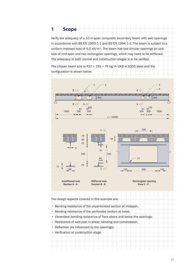
87
1 Scope
Verify the adequacy of a 10 m span composite secondary beam with web openings in accordance with BS EN 1993-1-1 and BS EN 1994-1-1. The beam is subject to a uniform imposed load of 5.0 kN/m2. The beam has two circular openings on one side of mid-span and two rectangular openings, which may need to be stiffened. The adequacy in both normal and construction stages is to be verified.
The chosen beam size is 457 × 191 × 74 kg/m UKB in S355 steel and the configuration is shown below.
B
Unstiffened webSection A - A
B
Stiffened webSection B - B
C
C
A
A
Rectangular openingView C - C
80
A
A
300
95 70
60
500190
9
300 300
3
4
10
150
300
150
500
L = 10000
500 3003001800 1800
1 2
75
75 15
15
400 150
330
The design aspects covered in this example are:
▪ Bending resistance of the unperforated section at midspan. ▪ Bending resistance of the perforated section at holes. ▪ Vierendeel bending resistance of Tees above and below the openings. ▪ Resistance of web-post in shear, bending and compression. ▪ Deflection (as influenced by the openings). ▪ Verification at construction stage.
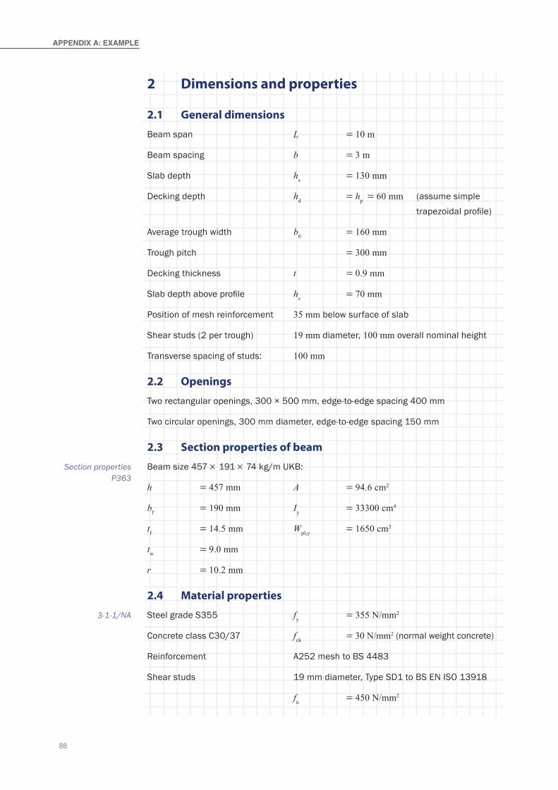
88
APPeNdIx A: exAMPLe
2 Dimensions and properties
2.1 General dimensions
Beam span L = 10 m
Beam spacing b = 3 m
Slab depth hs = 130 mm
Decking depth hd = hp = 60 mm (assume simple trapezoidal profile)
Average trough width b0 = 160 mm
Trough pitch = 300 mm
Decking thickness t = 0.9 mm
Slab depth above profile hc = 70 mm
Position of mesh reinforcement 35 mm below surface of slab
Shear studs (2 per trough) 19 mm diameter, 100 mm overall nominal height
Transverse spacing of studs: 100 mm
2.2 Openings
Two rectangular openings, 300 × 500 mm, edge-to-edge spacing 400 mm
Two circular openings, 300 mm diameter, edge-to-edge spacing 150 mm
2.3 Section properties of beam
Beam size 457 × 191 × 74 kg/m UKB:
h = 457 mm A = 94.6 cm2
bf = 190 mm Iy = 33300 cm4
tf = 14.5 mm Wpl,y = 1650 cm3
tw = 9.0 mm
r = 10.2 mm
2.4 Material properties
Steel grade S355 fy = 355 N/mm2
Concrete class C30/37 fck = 30 N/mm2 (normal weight concrete)
Reinforcement A252 mesh to BS 4483
Shear studs 19 mm diameter, Type SD1 to BS EN ISO 13918
fu = 450 N/mm2
Section properties P363
3-1-1/NA

89
3 Actions
3.1 Construction stage
Permanent actions
Self weight of beam 0.75 kN/m ≡ 0.25 kN/m2
Self weight of decking 0.1 kN/m2
Self weight of mesh 0.05 kN/m2
Total permanent actions gk = 0.4 kN/m2
Variable actions
Weight of wet concrete 2.55 kN/m2 (25 kN/m3 × 0.102 m2/m width)
Construction load 0.75 kN/m2
Total variable actions qk = 3.3 kN/m2
3.2 Composite stage
Permanent actions
Self weight of beam 0.25 kN/m2
Self weight of decking 0.1 kN/m2
Self weight of mesh 0.05 kN/m2
Self weight of slab 2.45 kN/m2 (24 kN/m3 × 0.102 m2/m width)
Finishes, services etc. 1.3 kN/m2
Total permanent actions gk = 4.15 kN/m2
Variable actions
Imposed load qk = 5.0 kN/m2
3.3 Partial factors for actions
Partial factor for permanent actions γG = 1.35
Partial factor for variable actions γQ = 1.50
Reduction factor ξ = 0.925
3.4 Design values of combined actions
Construction stage γG gk + γQ qk
= 0.4 × 1.35 + 3.3 × 1.5 = 5.49 kN/m2
BS EN 1990 Table NA.A1.2(B)
(6.10)
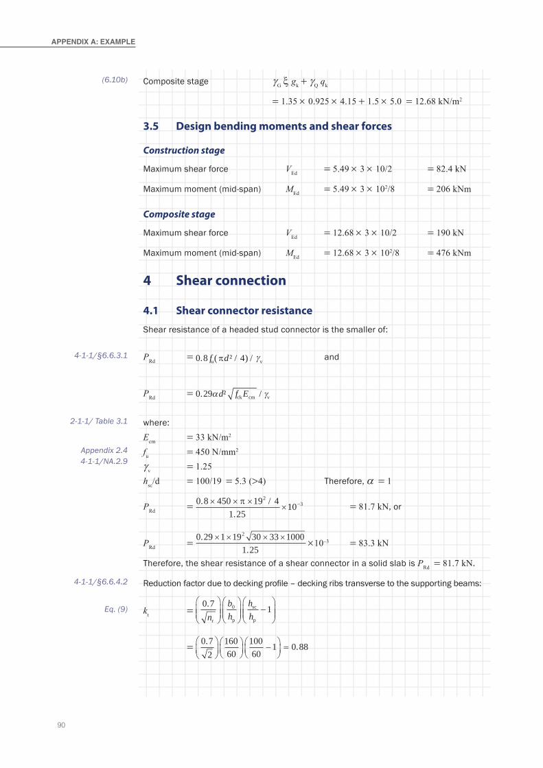
90
APPeNdIx A: exAMPLe
Composite stage γG ξ gk + γQ qk
= 1.35 × 0.925 × 4.15 + 1.5 × 5.0 = 12.68 kN/m2
3.5 Design bending moments and shear forces
Construction stage
Maximum shear force VEd = 5.49 × 3 × 10/2 = 82.4 kN
Maximum moment (mid-span) MEd = 5.49 × 3 × 102/8 = 206 kNm
Composite stage
Maximum shear force VEd = 12.68 × 3 × 10/2 = 190 kN
Maximum moment (mid-span) MEd = 12.68 × 3 × 102/8 = 476 kNm
4 Shear connection
4.1 Shear connector resistance
Shear resistance of a headed stud connector is the smaller of:
PRd = 0 8 4. ( ² / ) /f du vπ γ and
PRd = 0 29. ² /α γd f Eck cm v
where:Ecm = 33 kN/m2
fu = 450 N/mm2
γv = 1.25hsc/d = 100/19 = 5.3 (>4) Therefore, a = 1
PRd = 0 8 450 19 41 25
102
3. /.
× × ×× −π = 81.7 kN, or
PRd = 0 29 1 19 30 33 1000
1 25
2..
× × × × ×10–3 = 83.3 kN
Therefore, the shear resistance of a shear connector in a solid slab is PRd = 81.7 kN.
Reduction factor due to decking profile – decking ribs transverse to the supporting beams:
kt = 0 7 1.n
bh
hhr
0
p
sc
p
−
= 0 7
216060
10060
1 0 88. .
−
=
(6.10b)
4-1-1/§6.6.3.1
2-1-1/ Table 3.1
Appendix 2.44-1-1/NA.2.9
4-1-1/§6.6.4.2
Eq. (9)
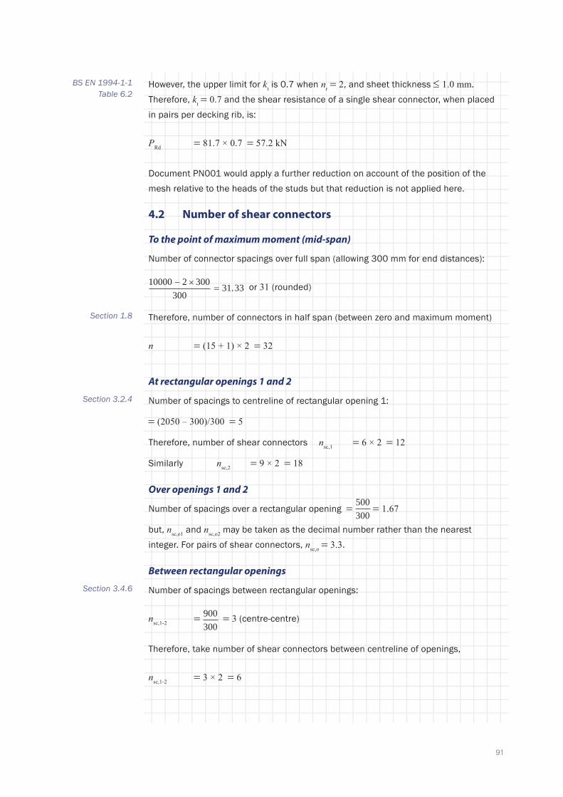
91
However, the upper limit for kt is 0.7 when nr = 2, and sheet thickness ≤ 1.0 mm. Therefore, kt = 0.7 and the shear resistance of a single shear connector, when placed in pairs per decking rib, is:
PRd = 81.7 × 0.7 = 57.2 kN
Document PN001 would apply a further reduction on account of the position of the mesh relative to the heads of the studs but that reduction is not applied here.
4.2 Number of shear connectors
To the point of maximum moment (mid-span)
Number of connector spacings over full span (allowing 300 mm for end distances):
10000 2 300300
31 33− ×= . or 31 (rounded)
Therefore, number of connectors in half span (between zero and maximum moment)
n = (15 + 1) × 2 = 32
At rectangular openings 1 and 2
Number of spacings to centreline of rectangular opening 1:
= (2050 – 300)/300 = 5
Therefore, number of shear connectors nsc,1 = 6 × 2 = 12
Similarly nsc,2 = 9 × 2 = 18
Over openings 1 and 2
Number of spacings over a rectangular opening = 500300
= 1.67
but, nsc,o1 and nsc,o2 may be taken as the decimal number rather than the nearest integer. For pairs of shear connectors, nsc,o = 3.3.
Between rectangular openings
Number of spacings between rectangular openings:
nsc,1-2 = 900300
= 3 (centre-centre)
Therefore, take number of shear connectors between centreline of openings,
nsc,1-2 = 3 × 2 = 6
BS EN 1994-1-1 Table 6.2
Section 1.8
Section 3.2.4
Section 3.4.6
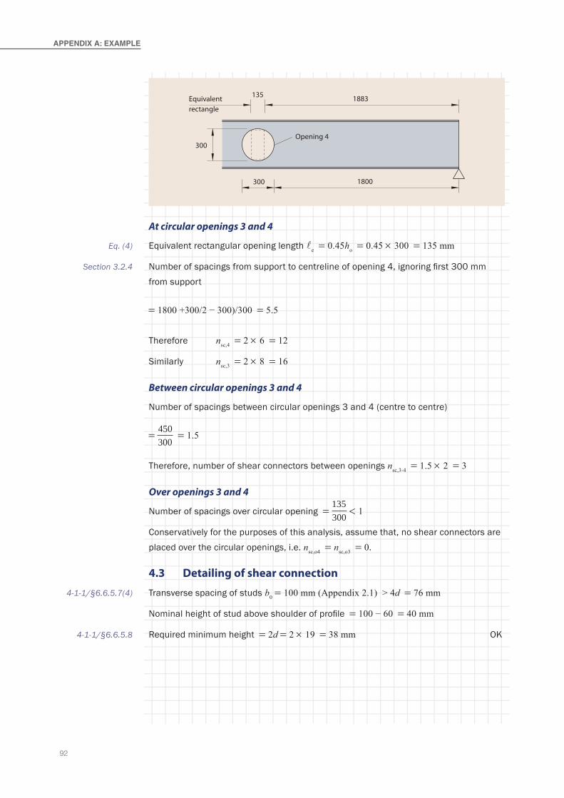
92
APPeNdIx A: exAMPLe
At circular openings 3 and 4
Equivalent rectangular opening length e = 0.45ho = 0.45 × 300 = 135 mm
Number of spacings from support to centreline of opening 4, ignoring first 300 mm from support
= 1800 +300/2 − 300)/300 = 5.5
Therefore nsc,4 = 2 × 6 = 12
Similarly nsc,3 = 2 × 8 = 16
Between circular openings 3 and 4
Number of spacings between circular openings 3 and 4 (centre to centre)
= 450300
= 1.5
Therefore, number of shear connectors between openings nsc,3-4 = 1.5 × 2 = 3
Over openings 3 and 4
Number of spacings over circular opening = 135300
< 1
Conservatively for the purposes of this analysis, assume that, no shear connectors are placed over the circular openings, i.e. nsc,o4 = nsc,o3 = 0.
4.3 Detailing of shear connection
Transverse spacing of studs b0 = 100 mm (Appendix 2.1) > 4d = 76 mm
Nominal height of stud above shoulder of profile = 100 − 60 = 40 mm
Required minimum height = 2d = 2 × 19 = 38 mm OK
Equivalentrectangle
300
300
135
Opening 4
1800
1883
Eq. (4)
Section 3.2.4
4-1-1/§6.6.5.7(4)
4-1-1/§6.6.5.8

93
5 Bending resistance at mid-span (composite stage)
Effective width of compression flange at mid-span, ignoring spacing of studs b0:
beff = span/4 = 2.5 m < 3 m (beam spacing)
Compressive resistance of slab
Nc,s,Rd = 0 85. f b hck eff c
cγ = 0 85 30 2500 70
1 510 3.
.× × ×
× − = 2975 kN
Tensile resistance of steel section
Na,Rd = Afy
M0
9460 3551.0γ
=×
× 10–3 = 3358 kN
Since Na,Rd > Nc,s,Rd, the plastic neutral axis lies in the steel section.
Degree of shear connection
Nc,max = nPRd = 32 × 57.2 = 1830 kN
The degree of shear connection at mid-span is:
η = NN
c,max
c,s,Rd
= 18302975
= 0.62
Limit on degree of shear connection:
For an equivalent span Le less than 25 m, the limit of η for symmetric sections with pairs of shear connectors is:
η ≥ 1 – 355fy
(0.75 – 0.03Le) ≥ 0.4
η ≥ 1 – 355355
(0.75 – 0.03 × 10) = 0.55
Since the actual degree of shear connection is 0.62, which exceeds 0.55, the minimum degree of shear connection is satisfied.
Bending resistance for full shear connection
Tensile resistance of steel flange:
Nf,Rd = b t ff f y
M0
γ
=× ×190 14 5 355
1 0..
× 10–3 = 978 kN
Section 1.7
Section 1.8
Eq. (1)
4-1-1/§6.6.1.2
4-1-1/(6.12)
94
APPeNdIx A: exAMPLe
Tensile resistance of web:
Nw,Rd = Na,Rd - 2Nf,Rd = 3358 - 2 × 978 = 1402 kN
Since Na,Rd > Ncm,Rd and Nw,Rd < Ncm,Rd the plastic neutral axis lies in the steel flange.
Taking moments about the top flange:
Mpl,Rd ≈ Ncm,Rd (hs + hp) / 2 + Na h/2
= [2975 × (130 + 60)/2 + 3358 × 457/2 ] × 10–3 = 1050 kNm
Bending resistance for partial shear connection
For partial shear connection, the bending resistance of the composite section is obtained by interpolation between that of the steel section and that of the composite section with full shear connection.
Bending resistance of steel section:
Mpl,a,Rd = Wpl,y fy
M0γ = 1650 × 355 × 10–3 = 586 kNm
Use linear interpolation:
MRd = Mpl,a,Rd + η (Mpl,Rd – Mpl,a,Rd )
= 586 + 0.62 × (1050 - 586) = 873 kNm
Since MRd = 873 kNm > MEd = 476 kNm, the design bending resistance at mid-span is satisfactory.
6 Design of beam at circular openings 3 and 4 (composite stage)
6.1 Geometric data
Centres of the openings are at x0,4 = 1.95 m and x0,3 = 2.4 m from the nearest end of the beam.
Diameter of opening = 300 mm
Height of equivalent rectangular opening, heo = 0.9ho = 0.9 × 300 = 270 mm
Length of equivalent rectangular opening for Vierendeel bending:
e = 0.45 × 300 = 135 mm
4-1-1/§6.2.1.3
4-1-1/§6.2.1.3
Eq. (3)
Appendix 3.5
Eq. (4)
Appendix 2(for properties of
steel section)
95
Effective length of opening for section classification of outstand of Tees:
o,eff = 0.7ho = 0.7 × 300 = 210 mm
Area of each of the two Tees:
AT = (A - ho tw)/2 = (9460 - 270 × 9.0)/2 = 3515 mm2
Depth of Tee hT = (h - heo)/2 = (457 - 270)/2 = 93.5 mm
Depth of web of Tee hw,T = hT - tf = 93.5 - 14.5 = 79 mm
Depth of elastic neutral axis of Tee from outer face of flange is given by:
zel =+ +( )b t t h h t
Af f f w,T w,T w
T
2 2 2
Neglecting the fillets of the Tee:
zel =× + +( ) × ×
× + ×190 14 5 2 14 5 79 2 79 9 0
190 14 5 79 9 0
2. . .. .
= 17 mm
Effective depth between centroids of Tees, heff = 457 - 2 × 17 = 423 mm
6.2 Design effects
Bending moment at the centreline of opening 4 (x0,4 = 1.95 m) is:
MEd = 190 × 1.95 - 12.69 × 3 × 1.952/2 = 299 kNm
Similarly, the moment at opening 3 is MEd = 347 kNm
Shear force at edge of equivalent opening 4 (at x0,4 - 0.135/2) is:
VEd = 190 - 12.69 × 3 × (1.95 - 0.135/2) = 119 kN
Shear force midway between the openings: (at x3-4 = 2.175) is:
VEd = 190 - 12.69 × 3 × 2.175 = 107 kN
6.3 Section classification
The top flange is Class 2, due to its attachment to the slab (shear connectors in mid-outstand at 300 mm spacing along the beam).
Classification of web outstand of the top Tee in Vierendeel bending (ignoring axial compression):
For the web to be Class 2, independent of its depth:o,eff < 32ε tw
Eq. (15)
Table 3.2

96
APPeNdIx A: exAMPLe
where:
ε = 235 235 355/ /fy = = 0.81
Therefore 32ε tw = 32 × 0.81 × 9.0 = 233 mm > o,eff = 210 mm
The Tee is Class 2 in Vierendeel bending.
The bottom Tee is thus also Class 2, irrespective of the tension force in the Tee (which would improve the classification).
6.4 Bending resistance at centreline of circular opening
The tensile resistance of the bottom Tee is given by:
NbT,Rd = A fbT y
M0γ=
×× −3515 355
1 010 3
. = 1250 kN
The compression resistance of the effective width of slab at the opening is given by:
Nc,Rd = min 0 85. ;f b h n Pcd eff,o c sc Rd { }
Neglecting b0, the effective width is given by:
beff,o = 3 16 4 4L x x Le e for + ≤
Distance from end support to centre of opening 4, x0,4 = 1950 mm
beff,o = 3 10000 16 1950 4× + = 2363 mm
nsc,4 = 12
Thus:
Nc,Rd
= × ( ) × × ×{ }= { } =
min . . ; .
min ;
0 85 30 1 5 2363 70 12 57 2
2811 686 6686 kN
The p.n.a. is therefore in the flange of the top Tee (Case 2 in Section 3.2.2). The plastic bending resistance is therefore given by:
Mc,Rd = N h N z h hbT,Rd eff c,Rd t s c+ + −( )0 5.
zt = zel = 17 mm
Mc,Rd = 1250 423 686 17 130 0 5 70 10 3× + × + − ×( ) × −. = 605 kNm
Eq. (5)
Eq. (6)
Eq. (11)
Appendix 4.2
Eq. (9)
Appendix 6.1
97
This bending resistance is adequate at both opening 4 and opening 3.
For the consideration of coexistent global bending, Vierendeel bending and shear at opening 4, the design tension force in the bottom Tee is required.
For Case 2, the value of NbT,Ed is given by the following (unless this exceeds Nc,Rd, see Section 3.2.2)
NbT,Ed M
h z h zEd
eff t s c
=+ + −( )0 5.
NbT,Ed =+ + − ×( )
×299
423 17 130 0 5 70103
. = 559 kN
The compression resistance of the slab is 686 kN and thus there is no requirement for the top Tee to resist axial compression at this opening. (If the tension force in the bottom Tee were greater than the slab resistance, then equation (10) would be used to determine the force in the bottom Tee and thus the compression in the top Tee.)
6.5 Shear resistance of perforated composite beam section
The design shear resistance is the sum of the resistances of the top and bottom Tees and the concrete slab:
VRd = Vt,Rd + Vb,Rd + Vc,Rd
Plastic shear resistance of a Tee section is given by:
Vpl,Rd = A fv y
M0
3γ
In which Av = A - bf tf + (2r + tw ) × 0.5 × tf
For plastic shear resistance, consider the full height of the circular opening, for which the area is given by:
AT = (A - ho tw)/2 = (9460 - 300 × 9.0)/2 = 3380 mm2
Av = 3380 - 190 × 14.5 + (2 × 10.2 + 9.0) × 7.25 = 838 mm2
Vt,Rd = Vb,Rd =×
=838 355 3
1 0172
. kN
Shear resistance of the concrete slab at an opening:
Vc,Rd = [CRd,c k (100ρ1 fck)1/3 + k1σcp ]bwd
Eq. (8)
3-1-1/§6.2.6
Eq. (12)

98
APPeNdIx A: exAMPLe
With a minimum value of:
Vc,Rd = [vmin + k1σcp ] bw d
Effective width of the slab bw = bf + 2hs,eff
hs,eff = 0.75hs = 0.75 × 130 = 97.5 mm
bw = 190 + 2 × 97.5 = 385 mm
CRd,c = c
=0 18 0 18
1 5. .
.γ = 0.12 and k1 = 0.15
k = d
+1 200 but ≤ 2.0
Effective depth of slab for shear, d = hc = 70 mm
k = +1 20070
= 2.69 > 2 and therefore, k = 2
Proportion of reinforcement:
ρ1 sl
w
= =×
=A
b d252
1000 700 > 0.020035.
The value of the first term in the expression for Vc,Rd is:
C k fRd,c ck1 3 100 0.5 2 N/mm2100 0 12 2 0 0035 301ρ( ) = × × × ×( ) =. .
The value of the first term in the expression for the minimum value, vmin is:
vmin k fck= = × × =0 035 0 035 2 30 0 54 N/mm23 2 1 2 3 2. . ./ /
So, use 0.54 N/mm2.
From above (Appendix 6.5), assuming no compression in the top Tee, the force in the slab at the opening equals the force in the bottom Tee = 556 kN.
Compression force acts over an effective width of beff = 2363 mm, and so:
Ac = hc bw = 70 × 1876 = 131 × 103 mm2
σcp = ××
=556 102363 70
3 36 N/mm23
.
k1σcp = 0.15 × 3.36 = 0.50 N/mm2
Eq. (13)
2-1-1/Table NA.1 (§6.2.2(1))
2-1-1/§6.2.2(1)
Section 3.3.2
2-1-1/Table NA.1 (§6.2.2(1))
Appendix 6.4
99
Total shear strength of concrete is:
Hence:
Vc,Rd = (0.54 + 0.50) × 385 × 70 × 10−3 = 28 kN
Hence:
VRd = Vc,Rd + Vt,Rd + Vb,Rd = 28 + 172 + 172 = 372 kN
This exceeds the design shear force at opening 4, VEd = 119 kN.
6.6 Bending resistance of Tees
Assumed distribution of shear force
Initially, assume that 50% of the shear force VEd is resisted in each Tee.
Since the shear force in each Tee (119/2 = 59.5 kN) is less than 0.5Vpl,Rd the web thickness does not need to be reduced when determining plastic bending resistance and axial resistance.
If the shear force in the bottom Tee is limited by Vierendeel bending resistance across the Tee, the shear forces may need to be redistributed.
Plastic bending resistance
For a Class 2 cross section, the plastic bending resistance of an unstiffened Tee, in the absence of axial force and high shear is given by:
Mpl,Rd = A f
h t zA f
. t z z t w,T y
M0w,T f pl
f y
M0f pl pl f0.5
γ γ+ −( ) + − +( )0 5 2
The depth of the plastic neutral axis of the Tee from the outer surface of the flange is given by:
zpl = A A
bf w,T
f
+( )2
190 14 5 79 9 02 190
× + ××. .= = 9.1 mm
Hence:
Mpl,Rd 0.5 14. 5
=× ×
× + −( ) ×
+× ×
−79 9 3551 0
79 9 1 10
190 14 5 3551 0
6
..
..
00 5 14 5 9 1 9 1 14 5 10 15 12 6. × − +( ) × =−. . . . . kNm
The plastic bending resistance of the bottom Tee is reduced for axial tension, as follows:
MbT,N,Rd M M NNp l,N,Rd pl,Rd
Ed
pl,Rd
= = −
12
Section 3.4.3
Eq. (19)
Eq. (26)
100
APPeNdIx A: exAMPLe
in which NEd = 559 kN and Npl,Rd = NbT,Rd = 1250 kN
Therefore, MbT,N,Rd = 15.1 × (1 – (559/1250)2) = 12.1 kNm
The plastic resistance of the top Tee is not reduced for axial force and thus:
MtT,N,Rd = 15.1 kNm
Composite bending resistance
As in the worst case, there are no shear connectors over the circular openings, thus no local composite action is developed. Therefore the component of Vierendeel bending resistance due to composite action is neglected (i.e. Mvc,Rd = 0).
6.7 Verification of resistance to Vierendeel bending
The criterion for adequacy of Vierendeel bending resistance is:
2MbT,NV,Rd + 2MtT,NV,Rd + Mvc,Rd ≥ VEd e
Thus, using the above values for the Tees, the criterion is:
2 × 12.1 + 2 × 15.1 + 0 = 54.2 kNm > 119 × 0.135 = 16.1 kNm OK
6.8 Web-post shear, bending and buckling between openings 3 and 4
For closely spaced circular openings, the resistance of the web-post in shear, bending or buckling might govern. Each of these resistances needs to be verified. (But web-post bending will only be critical when the distribution of shear between the Tees is radically different.)
Web-post bending resistance
Elastic bending resistance of web-post (at mid-height between circular openings):
Mwp,Rd = so² tw fy / 6 = (450–300)² × 9.0 × 355 × 10–6/ 6 = 11.9 kNm
Since the Vierendeel bending resistance was verified above for equal shear force in each of the Tees, with no shear force in the slab, the web-post moment at mid-height Mwp,Ed = 0. Hence verification of bending resistance at the top and bottom of the openings is not needed for circular openings.
Web-post shear resistance
Check whether there is sufficient shear connection to develop a force in the slab equal to the incremental force in the bottom Tee.
Appendix 6.4
Eq. (14)
Eq. (44)

101
There is sufficient connection if Vwp.Ed ≤ ∆Ncs,Rd
Vwp,Ed = V sh z h h
Ed
eff t s c+ + −( )0 5.
Taking the value of VEd mid-way between the openings:
Vwp,Ed = ×+ + − ×( )
107 450423 17 130 0 5 70.
= 90 kN
∆Ncs,Rd = nsc,sPRd
For nsc,3-4 = 3:
∆Ncs,Rd = 3 × 57.2 = 171 kN
So there is sufficient shear connection between the centrelines of the openings.
Shear resistance of web-post
The longitudinal shear resistance of the web-post is given by:
Vwp,Rd = s t fo w y
M0
( ) 3γ
= 150 × 9.0 × 0.577 × 355 × 10–3
= 276 kN > Vwp,Ed = 90 kN
Web-post buckling resistance
Web-post buckling may be treated by considering the compressive stress due to an effective longitudinal force in the web-post.
Since the openings are placed centrally in the web depth and the web-post moment required at mid-height Mwp,Ed = 0, Nwp,Ed = Vwp,Ed.
Hence Nwp,Ed = 90 kN.
Edge-to-edge distance between openings 3 and 4 = 150 mm, which is less than ho and thus the openings are classed as ‘closely spaced’.
Non-dimensional slenderness ratio of web-post:
λ = 1 75 12 2
1
. s ht
o o
w
+λ
1λ = 76 for S355
λ = 1 75 150 3009 0
176
0 862 2.
..+
=
Eq. (29)
Appendix 4.2
Eq. (36)
Eq. (33)
Section 3.5.3
Eq. (40)
102
APPeNdIx A: exAMPLe
The reduction factor for flexural buckling is calculated using the factor φ, given by:
φ λ λ= + − +0 5 1 0 22
. ( ( . ) )α
For a welded section, use buckling curve c, for which a = 0.49
Thus φ = + − + =0 5 1 0 49 0 86 0 2 0 86 1 032. ( . ( . . ) . ) .
The reduction factor χ is given by:
χ = 12 2 0 5
φ φ λ+ −( ) .
= 1
1 03 1 03 0 860 63
2 2 0 5. . .
..+ −( )
=
Nwp,Rd = χ s t fo w y
M1γ
Nwp,Rd = 0 63 150 9 3551 0
..
× × × × 10-3 = 302 kN > Nwp,Ed = 90 kN OK
7 Design of beam at rectangular openings 1 and 2
7.1 Geometric data
Centres of the openings are at x0,1 = 2.05 m and x0,2 = 2.95 m from the nearest end of the beam.
Height of openings ho = 300 mm
Area of each of the two Tees:
AT = (A - hotw)/2 = (9460 - 300 × 9.0)/2 = 3380 mm2
Depth of Tee hT = (h - ho)/2 = (457 - 300)/2 = 78.5 mm
Depth of web of Tee hw,T = hT - tf = 78.5 - 14.5 = 64 mm
Depth of elastic neutral axis of Tee from outer face of flange is given by:
zel b t t h h t
Af f f w,T w,T w
T
=+ +( )2 2 2
Neglecting the fillets of the Tee:
zel =× + +( ) × ×
× + ×190 14 5 2 14 5 64 2 64 9 0
190 14 5 64 9 0
2. . .. .
= 14.0 mm
Effective depth between centroids of Tees, heff = 457 - 2 × 14 = 429 mm
The effective length of the openings for section classification of the Tees is o,eff = 500 mm.
3-1-1/§6.3.1.2
Eq. (42)
103
7.2 Design effects
Bending moment at centreline of opening 1 (x0,1 = 2050 mm) is:
MEd = 190 × 2.05 - 12.69 × 3 × 2.052/2 = 310 kNm
Similarly, the moment at opening 2 is 395 kNm.
Shear force at the edge of opening 1 (at x0,1 - 0.500/2) is:
VEd = 190 - 12.69 × 3 × (2.05 - 0.250) = 121 kN
Similarly, the shear force at opening 2 is 87 kN.
The shear force midway between the openings is 95 kN.
7.3 Section classification
The top flange is treated as Class 2 due to its attachment to the slab.
Classification of web outstand of the top Tee in Vierendeel bending (ignoring axial compression).
For the unstiffened web to be Class 2, independent of its depth:
o,eff < 32ε t w
From Appendix 6.7 this limit is o,eff = 210 mm and thus the limiting depth for Class 2 has to be determined.
The limiting depth of the web of the Tee is given by:
10
1 322
t
t
w
w
o,eff
ε
ε−
�
10 9 0 0 81
1 32 9 0 0 81500
2
× ×
−× ×
. .
. .= = 82 mm > hw = 64 mm
Therefore the Tee sections at the rectangular openings 1 and 2 are Class 2.
7.4 Bending resistance at centreline of rectangular opening
Unstiffened openings
The tensile resistance of the bottom Tee is given by:
NbT,Rd A fbT y
M0
= =×
× =−
γ3380 355
1 010 1200 kN3
.
The compression resistance of the effective width of slab at the opening is given by:
Nc,Rd f b h n Pcd eff,o c sc Rd = { }min . ;0 85
Table 3.2
Eq. (5)
Eq. (6)
104
APPeNdIx A: exAMPLe
Neglecting b0 the effective width is given by:
beff,o = 3Le/16 + x/4 for x ≤ Le/4
Distance from end support to centre of opening 1, x0,1 = 2050 mm
beff,o = 3 × 10000/16 + 2050/4 = 2388 mm
nsc,1 = 12
Thus:
Nc,Rd
= × ( ) × × ×{ }= { } =
min . . ; .
min ;
0 85 30 1 5 2388 70 12 57 2
2842 686 6686 kN
For opening 2, nsc,2 = 18
The p.n.a. is therefore in the flange of the top Tee (Case 2 in Section 3.2.2). The plastic bending resistance is therefore given by:
Mo,Rd N h N z h hbT,Rd eff c,Rd t s c= + + −( )0 5.
Mo,Rd = × + × + − ×( ) × −1200 429 686 14 130 0 5 70 10 3. = 590 kNm
This bending resistance is adequate at both opening 1 and opening 2.
For the consideration of coexistent global bending, Vierendeel bending and shear at opening 1 (which has higher shear than opening 2), the design tension force in the bottom Tee is required.
For Case 2, the value of NbT,Ed is given by the following (unless this exceeds Nc,Rd, see Section 3.2.2):
NbT,Ed M
h z h zEd
eff t s c
=+ + −( )0 5.
NbT,Ed =+ + − ×( )
×310
429 14 130 0 5 70103
.= 576 kN at opening 1
The compression resistance of the slab is 686 kN and thus there is no requirement for the top Tee to resist axial compression at this opening. (If the tension force in the bottom Tee were greater than the slab resistance, then equation (10) would be used to determine the force in the bottom Tee and thus the compression in the top Tee.)
By a similar calculation, NbT,Ed = 734 kN at opening 2, which is greater than Nc,Rd (= 1030 kN, for nsc,2 = 18), so equation (8) may still be used.
Eq. (11)
Appendix 4.2
Appendix 4.2
Eq. (9)
Eq. (8)

105
7.5 Shear resistance of perforated composite beam section
As for the circular openings:
Vpl,Rd = 172 kN (for each Tee)
The effective width of slab for shear is the same as for the circular openings:
bw = 385 mm
Depth of concrete for shear resistance = 70 mm
Assuming no stress in the top Tee, the stress in the concrete at opening 1 is given for an effective width of 2388 mm by:
σcp bT,Ed
eff,o
= =××
Nb d
576 102388 70
3
= 3.44 N/mm2
Thus k1σcp = 0.15 × 3.44 = 0.52 N/mm2
Hence the concrete shear resistance is:
Vc,Rd = (0.54 + 0.52) × 385 × 70 × 10−3 = 28 kN for opening 1
Similarly, for opening 2, Vc,Rd = 32 kN
7.6 Bending resistance of unstiffened Tees
Initial assumption of distribution of shear force
Initially, assume that 50% of the shear force VEd is resisted in each Tee.
Later, the shear force may be re-distributed between the Tees, depending on the shear force that can be transferred by Vierendeel bending of the bottom Tee. The amount of redistribution may also be limited by the need to minimize the web-post moment at mid-height of the opening; the adequacy of shear resistance for an assumption of MWp,Ed = 0 will be verified in Section 7.8.
Since this shear force in each Tee (121/2 = 60.5 kN) is less than 0.5Vpl,Rd (= 172 kN, see Appendix 6.5), the web thickness does not need to be reduced for determining plastic bending resistance and axial resistance.
Plastic bending resistance
For a Class 2 cross section, the plastic bending resistance of an unstiffened Tee, in the absence of axial force and high shear is given by:
Mpl,Rd = A f
h t zA f
. t z z tw,T y
M0w,T f pl
f y
M0f pl pl f0.5
γ γ+ −( ) + − +( )0 5 2
Appendix 6.5
Eq. (19)
106
APPeNdIx A: exAMPLe
The depth of the plastic neutral axis of the Tee from the outer surface of the flange is given by:
zpl = A A
bf w,T
f
+( )2
190 14 5 64 9 02 190
× + ××. .
= = 8.8 mm
Hence:
Mpl,Rd 0.5 64 14.5
=× ×
× + −( ) ×
+× ×
−64 9 3551 0
8 8 10
190 14 5 3551 0
6
..
..
00 5 14 5 8 8 8 8 14 5 10 11 42 6. × − +( ) × =−. . . . . kNm
The plastic bending resistance of the bottom Tee is reduced for axial tension, as follows:
MbT,N,Rd M M NNpl,N,Rd pl,Rd
Ed
pl,Rd
= = −
12
NEd = 576 kN at opening 1 NEd = 734 kN at opening 2Nb,Rd = Nb = 1200 kN
Therefore MbT,N,Rd = 11.4 × (1 - (576/1200)2) = 8.8 kNm at opening 1
and MbT,N,Rd = 11.4 × (1 - (734/1200)2) = 7.1 kNm at opening 2
Composite Vierendeel bending resistance
The compression force developed in the slab due to composite action over the opening:
∆Nc,Rd = nsc,oPRd = 3.3 × 57.2 = 188 kN
For unstiffened openings, reduction factor due to the length of the openings, ko is given by:
ko = 1 - o/(25ht) = 1 - 500/(25 × 78.5) = 0.75
where ht = depth of top Tee = 78.5 mm.
Vierendeel bending resistance due to local composite action is given by:
Mvc,Rd = ∆Nc,Rd (hs + zt - 0.5 hc ) ko
= 188 × (130 + 14 - 35) × 10–3 × 0.75 = 15.4 kNm
Verification of Vierendeel bending resistance
The criterion for adequacy of Vierendeel bending resistance is:
2MbT,NV,Rd + 2MtT,NV,Rd + Mvc,Rd ≥ VEd e
Eq. (20)
Appendix 7.4
Eq. (25)
Eq. (24)
Eq. (14)
107
Thus, using the above values for the Tees, the total Vierendeel resistances are:
At opening 1:
2 × 8.8 + 2 × 11.4 + 15.4 = 55.6 kNm
At opening 2:
2 × 7.1 + 2 × 11.4 + 15.4 = 52.4 kNm
The design values of the Vierendeel moments are:
Mv = VEdo = 121 × 0.5 = 60.5 kNm at opening 1 ( > 55.6 kNm)
Mv = VEdo = 87 × 0.5 = 43.5 kNm at opening 2 ( < 52.4 kNm)
Opening 1 will therefore need to be stiffened.
Opening 2 does not need to be stiffened.
In mobilizing the full Vierendeel bending resistance of the top Tee, it will resist a shear of 2 × 11.4/0.500 = 45.6 kN. This is only 27% of the plastic shear resistance, so there is no need to reduce the bending resistance for coexistent shear stress.
7.7 Bending resistance of stiffened opening 1
Section properties for stiffened Tees
A 80 × 10 flat plate is welded to both Tees such that there is a clear distance of 10 mm from the edge of the opening to the face of the web. The centroid of the flat is thus 63.5 mm from the outer face of the flange.
The outstand ratio of the plate = 80/10 = 8, which is within the class 2 limit for outstands (i.e. 10ε = 8.1 for S355).
Area of stiffener Ar = 80 × 10 = 800 mm2
The depth of the elastic neutral axis from the outer face of the flange will have increased, due to the addition of the stiffener, and is now:
zel = 14 0 3380 800 63 53380 800
. .× + ×+
= 24 mm
The distance between the centroids of the two stiffened Tees is:
heff = 457 - 2 × 24 = 409 mm
108
APPeNdIx A: exAMPLe
Since the area of the web (64 × 9 = 576 mm2) plus the stiffener, is less than that of the flange (190 × 14.5 = 2755 mm2) the plastic axis of the Tee is in the flange and the depth of the p.n.a. is given by:
zpl = 190 14 5 64 9 0 80 102 190
10 9× + × + ××
=. . . mm
Tensile resistance of stiffened bottom Tee:
NbT,Rd = 1200 + 80 × 10 × 355 × 10–3 = 1484 kN
The plastic resistance of the Tee is:
Mpl,Rd A f h t z
A ft z z tw,T y
M0
wtf pl
f y
M0f pl pl f= + −
+ − +(
γ γ20 5 2. ))
+ + − −( )A ft h e zr y
M0f w,T r plγ
Mpl,Rd =× ×
+ −
+
× ×64 9 3551 0
642
14 5 10 9 190 14 5 3551 0
14.
. . ..
.. . ..
.. .
52
10 9 10 914 5
80 10 3551 0
14 5 64 15 10 9
2
− +
+× ×
+ − −(
))
× −10 6
= 7.3 + 4.4 + 14.9 = 26.6 kNm
Force in bottom Tee
With the stiffened top Tee, the p.n.a. of the composite section is still in the flange (Case 2 in Section 3.2.2) and the bending resistance of the composite section is given by:
Mo,Rd = NbT,Rd heff + Nc,Rd (zt + hs - 0.5hc)
Mo,Rd = [1480 × 409 + 686 × (14 + 130 - 0.5 × 70)] × 10-3 = 682 kNm
Since the resistance of the unstiffened section was adequate, this check is not strictly needed but is included for completeness.
For Case 2, the tension force in the bottom Tee is given by:
NbT,Ed M
h z h zEd
eff t s c
=+ + −( )0 5.
NbT,Ed =+ + − ×( )
×310
409 24 130 0 5 70103
. = 587 kN at opening 1
Eq. (57)
Eq. (9)
Eq. (8)
109
Vierendeel bending resistance
The bending resistance of the stiffened bottom Tee subject to axial tension is reduced by linear interaction, according to:
MbT,N,Rd = Mpl,Rd 1 −
NN
bT,Ed
bT,Rd
= 26.6 × (1 - (587/1484)) = 16.1 kNm
For stiffened openings, the reduction factor on the Vierendeel bending resistance due to composite action due to the length of opening, ko is given by:
ko = 1 - o /(35 ht) = 1 - 500/(35 × 78.5) = 0.82
Vierendeel bending resistance due to local composite action is given by:
Mvc,Rd = ∆Nc,Rd (hs - 0.5 hc + zt) ko
= 188 × (14 + 95) × 10–3 × 0.82 = 16.8 kNm
A less conservative reduction due to the length of the opening could be obtained using the alternative method in Section 3.4.6 and the values given by Table 3.3 but this is not evaluated here.
The criterion for adequacy of Vierendeel bending resistance is:
2MbT,NV,Rd + 2MtT,NV,Rd + Mvc,Rd ≥ VEde
Thus, using the above values for the Tees, the total resistance is:
2 × 16.1 + 2 × 26.6 + 16.8 = 102.2 kNm
The design value of Vierendeel moment at opening 1 is:
Mv = VEdo = 121 × 0.5 = 60.5 kNm
Therefore, the stiffened opening is adequate for Vierendeel bending resistance.
If the resistance were fully utilized, the shear in the top Tee would be:
2 × 26.6/0.5 = 106 kN
This is greater than 50% of Vpl,Rd ( = 172 kN, see Appendix 6.5) and MtT,NV,Rd would need to be reduced for shear. Here the utilization of Vierendeel bending resistance is only 60.5/102 = 59% and thus no reduction is necessary.
Section 5.2.5
Eq. (60)
Eq. (61)
Eq. (24)
Eq. (14)
110
APPeNdIx A: exAMPLe
7.8 Web-post shear, bending and buckling
For closely spaced rectangular openings, the Vierendeel bending resistance is potentially limited by the bending resistance of the adjacent web-post.
Check whether there is sufficient shear connection to develop a force in the slab over the distance between the centrelines of the openings that is equal to the incremental force in the bottom Tee.
If there is sufficient shear connection, Vwp,Ed ≤ ∆Ncs,Rd
Vwp,Ed = V sh z h h
Ed
eff t s c+ + −( )0 5.
Taking the value of VEd mid way between the centrelines of the openings and heff for the stiffened opening:
Vwp,Ed = 95 900409 24 130 0 5 70
×+ + − ×( ).
= 162 kN
∆Ncs,Rd = nsc,sPRd
For nsc,1-2 = 6
∆Ncs,Rd = 6 × 57.2 = 343 kN
So there is sufficient shear connection between the centrelines of the openings.
Shear resistance of web-post
The longitudinal shear resistance of the web-post is given by:
Vwp,Rd s t fo w y
M0
= =( ) 3
γ400 9 0 355
310 3× ×
×. - = 738 kN
Shear resistance of web-post is adequate.
Bending resistance of web-post
Elastic bending resistance of web-post:
Mwp,Rd = s to w2
6fy
M0γ
= 400² × 9.0 × 355 / 6 × 10–6 = 85.2 kNm
The shear resistance of the beam, as limited by web-post bending, is the smaller of:
VRd = 2 4
1 20 5
M s Me h h
Ns
z h he
wp,Rd bT,NV,Rd o
o o ff
cst s c
/ //
.+
+ +( )+ + −( )
� ∆
Eq. (29)
Appendix 4.2
Eq. (36)
Eq. (44)
Eq. (50)
111
and:
VRd = 2 / 4 /0.5
2wp,Rd bT,N,Rd oeff s c
eff o o
M s Mh h hh e h
+ + −[ ]+ +[ ]
�
Since one opening is stiffened and one unstiffened, use the mean value of Vierendeel resistance of both Tees:
MbT,N,Rd = (16.1 + 7.1)/2 = 11.6 kNm
Thus the shear resistance, as limited by web-post bending, is the lesser of:
VRd = 2 85 2/900 4 11 6 5001 0 300 409
10 342900
24 130 0 5 703× + ×+ +( )
× + + − ×(. . //
. )) = 208 kN
and
VRd = 2 4 10 /500 100.5 703 3× + × × × ×
+ − ×[ ]+ +
85 2 900 11 6409 130
409 0 30. / .
00[ ] = 201 kN
Hence, VRd = 201 kN > VEd = 95 kN
The elastic bending resistance of the web-post Mwp,Rd does not limit the shear resistance.
The compression force in the web-post is minimized by minimizing the value of the web-post moment at the mid-height of the opening. If a value of Mwp,Ed = 0 is assumed, the moment at the top of the web-post is given by Vwp,Ed × ho/2 (= 162 × 0.15 = 24.2 kNm). Inserting this value into the above expressions for the shear resistance limited by web-post bending gives VRd = 104 kN > VEd = 95 kN. Thus the assumption of Mwp,Ed = 0 is consistent with the verification of shear resistance and the following verification of resistance to web-post buckling.
Web-post buckling
For closely spaced openings, the effective compression force in the web-post is given by:
Nwp,Ed = Vwp,Ed + |Mwp,Ed|/(ho/2)
As noted above, it may be assumed that Mwp,Ed = 0.
Hence, Nwp,Ed = Vwp,Ed + 0 = 162 kN
Since so < o, the openings are closely spaced and the web-post slenderness is given by:
λ λ=
+2 5 12 2
1
. s ht
o o
w
λ =+
=2 5 400 300
9 0176
1 832 2..
.
Eq. (51)
Appendix 7.6 and 7.7
Appendix 7.2
Eq. (33)
Appendix 7.8
Eq. (41)
112
APPeNdIx A: exAMPLe
Thus:
φ λ λ= + − + =0 5 1 0 2 2 572
. ( ( . ) ) .α , where a = 0.49 (buckling curve c), and;
χ = 12 2 0 5
φ φ λ+ −( ) . = [2.57 + (2.572 - 1.832)0.5]–1 = 0.23
Nwp,Rd = χs t fo w y
M1
=× ×
× −0 23 400 9 3551 0
10 3..γ = 292 kN > Nwp,Ed = 162 kN OK
The closed solution for vertical shear resistance, as limited by web-post buckling, for the case where there is full shear connection between the openings is given by:
VRd = N h s Mh h h
h h ewp,Rd o bT,NV,Rd o
eff s c
eff o o
/ /.
( ) + + −[ ]+ +[ ]
40 5
2�
VRd = 292 300 900 4 11 6 0 500409 130 0 5 70
409 300 0/ . / .
.( ) + ×
+ − ×[ ]+ +[ ]
= 134 kN
Hence, VRd = 134 kN > VEd = 95 kN OK
This value of shear resistance is greater than the value limited by web-post bending when it is assumed that Mwp,Ed = 0 (VRd = 104 kN). The lower value governs.
8 Construction stage
The construction stage is rarely a critical design situation and the verification is performed here for completeness, having earlier determined the section properties of the beam at the opening.
Consider the design of the stiffened rectangular opening:
Design loads at construction stage qd = 5.49 kN/m2
Maximum moment in mid span MEd = 206 kNm
Maximum moment at a rectangular opening:
Mo,Ed = (5.49 × 3 × 5) × 2.05 - 5.49 × 3 × 2.052/2 = 134 kNm
Shear force at opening, VEd = 5.49 × 3 × (5 - 1.8) = 52.7 kN
Bending resistance of unperforated steel beam:
MRd = Wpl,y fy /γM0 = 1650 × 103 × 355 × 10–6 = 586 kNm > 195 kNm
Bending resistance of steel beam at an opening:
Mo,Rd = 586 - 9.0 × 3002 × 355 × 10–6/6 = 538 kNm > 137 kNm
Eq. (42)
Eq. (53)
Appendix 3.4
3-1-1/§6.3.1.2
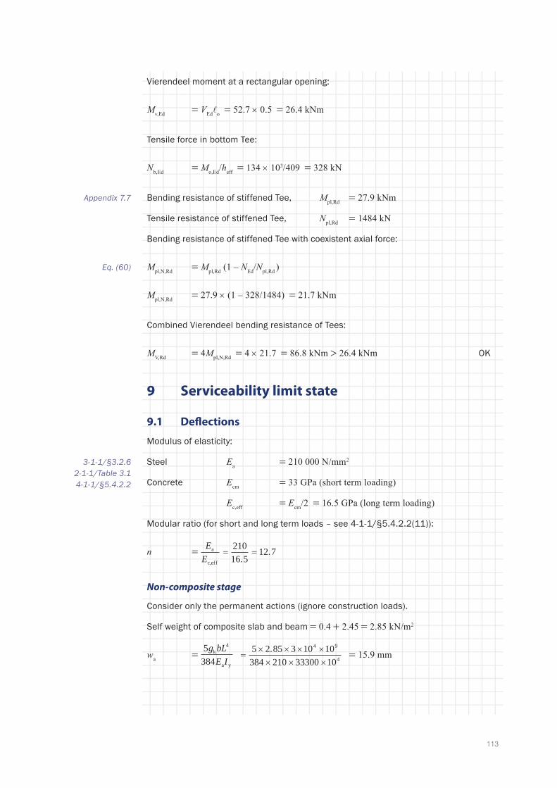
113
Vierendeel moment at a rectangular opening:
Mv,Ed = VEdo = 52.7 × 0.5 = 26.4 kNm
Tensile force in bottom Tee:
Nb,Ed = Mo,Ed/heff = 134 × 103/409 = 328 kN
Bending resistance of stiffened Tee, Mpl,Rd = 27.9 kNm
Tensile resistance of stiffened Tee, Npl,Rd = 1484 kN
Bending resistance of stiffened Tee with coexistent axial force:
Mpl,N,Rd = Mpl,Rd (1 – NEd/Npl,Rd )
Mpl,N,Rd = 27.9 × (1 – 328/1484) = 21.7 kNm
Combined Vierendeel bending resistance of Tees:
MV,Rd = 4Mpl,N,Rd = 4 × 21.7 = 86.8 kNm > 26.4 kNm OK
9 Serviceability limit state
9.1 Deflections
Modulus of elasticity:
Steel Ea = 210 000 N/mm2
Concrete Ecm = 33 GPa (short term loading)
Ec,eff = Ecm/2 = 16.5 GPa (long term loading)
Modular ratio (for short and long term loads – see 4-1-1/§5.4.2.2(11)):
n = EE
a
c,eff
= =21016 5
12 7.
.
Non-composite stage
Consider only the permanent actions (ignore construction loads).
Self weight of composite slab and beam = 0.4 + 2.45 = 2.85 kN/m2
wa = 5384
4g bLE I
k
ya
5 2 85 3 10 10384 210 33300 10
4 9
4
× × × ×× × ×.
= = 15.9 mm
Appendix 7.7
Eq. (60)
3-1-1/§3.2.62-1-1/Table 3.14-1-1/§5.4.2.2

114
APPeNdIx A: exAMPLe
Composite stage
Finishes gk = 1.3 kN/m²
Imposed load qk = 5.0 kN/m²
Composite second moment of area (remote from opening), can be expressed as:
Iy = A h h h
nrb h
nI
+ +( )+( )
+ +s p eff cy
2 3
4 1 12
where:
r = A
b heff c
94602500 70×
= = 0.054
Iy = 9460 457 130 60
4 1 12 7 0 0542500 7012 12 7
33300 102 3× + +( )
+ ×( )+
××
+ ×. . .
44
Iy = 926 × 106 mm4
Deflection due to finishes and imposed load:
wi = 5384
5 6 3 3 10384 210 926 10
4 4
6
q bLE I
k
a y
910 =
× × × ×× × ×. = 12.7 mm
(Assuming full shear connection.)
For this design situation, the effects of partial shear connection on slip may be neglected, as the degree of shear connection exceeds 0.5. Hence:
Total deflection w = 15.9 + 12.7 = 28.6 mm
Additional deflection due to openings, wadd
For each opening, the additional deflection due to the presence of the opening is given by:
wwadd k
Lhh
xLo
o o=
−
� 1
where ko = 1.0 for stiffened openings and ko = 1.5 for unstiffened openings.
For opening 1 (stiffened rectangular):
wwadd =
−
1 0 0 5
100 3
0 4571 2 05
10. . .
..
= 0.026
For opening 2 (unstiffened rectangular):
wwadd =
−
1 5 0 5
100 3
0 4571 2 95
10. . .
..
= 0.035
4-1-1/§7.3.1(4)
Eq. (65)

115
For opening 3 (circular):
wwadd =
−
1 5 0 135
100 3
0 04571 2 40
10. . .
..
= 0.010
For opening 4 (circular):
wwadd =
−
1 5 0 135
100 3
0 4571 1 95
10. . .
..
= 0.011
Total deflection due to openings:
wadd = (0.026 + 0.035 + 0.010 + 0.011) × 31.2 = 0.082 × 28.6 = 2.3 mm
The deflection due to imposed load alone, after allowing for the openings, is:
12.7 × (1 + 0.082) × 5.0/6.3 = 10.9 mm
This is less than span/360 (= 27.7 mm), which is a commonly applied limit for imposed loads.
Total deflection = 28.6 + 2.3 = 30.9 mm
This is equivalent to L/323, which is less than L/250, a commonly applied total deflection limit for beams with raised floor and suspended ceiling.
9.2 Vibrations
For the serviceability limit state, the natural frequency for vibrations should be kept above an appropriate value for comfort to users.
The frequent combination of actions should be used.
The frequent combination is expressed as:
G P Q Qjj
ii
ik,1
1,1 k,1 2,1
k,≥ >
∑ ∑+ + +ψ ψ
For Category A and B buildings, ψ1 = 0.5 and thus the total design value of actions are:
Self weight 2.85 × 1.0 = 2.85 kN/m²
Finishes 1.3 × 1.0 = 1.3 kN/m²
Imposed load 5.0 × 0.5 = 2.5 kN/m2
6.45 kN/m2
For natural frequency, use the dynamic modulus for concrete to determine the second moment of area of the composite section.
From P354, Ec,dyn = 38 kN/mm2 and thus n = 210/38 = 5.53
BS EN 1990/A1.4.4
NA.2.2.6
BS EN 1990/ Table NA.A1.1
P354

116
APPeNdIx A: exAMPLe
Use r = 0.054, as above, thus:
Iy = 9460 457 130 604 1 5 33 0 054
2500 7012 5 33
33300 102 3× + +( )
+ ×( )+
××
+ ×. . .
44
Iy = 1120 × 106 mm4
The effect of the openings is to add approximately 8% to the deflection of the beam. Therefore, use Iy1 = 0.92 × 1120 × 106 mm4 = 1030 × 106 mm4
wsw = 5384
3q bLE I
sw
a y1
5 6 45 3 0 10 10384 210 1030 10
4 9
6
× × × ×× × ×. .= = 11.6 mm
f = 18wsw
1811 6.
= = 5.3 Hz
A detailed assessment of the dynamic response of the whole floor may be needed, taking account of floor configuration and building use (see SCI publication P354 [24]).

117


SCI Membership
Technical Information
Construction Solutions
Communications Technology
SCI Assessment
sCi Silwood Park, Ascot, Berkshire. SL5 7QN UKT: +44 (0)1344 636525F: +44 (0)1344 636570E: [email protected] www.steel-sci.com
SCI Ref: P355ISBN: 978-1-85942-197-0
P361
Introduction to the Eurocodes
P362
Concise Eurocodes
P363
Design Data (The Blue Book)
Composite floor beams are a preferred solution for multi-storey construction – this type of construction can achieve long spans and openings in the web of the steel section facilitating service integration within the structural zone. This design guide provides comprehensive coverage of the design of a full range of fabricated and rolled beams with isolated and regularly spaced circular or rectangular web openings. The guide also covers the design of asymmetric steel sections, elongated round openings, stiffened openings and notched beams.
Design guidance has been prepared in a way that compliments design to the Eurocodes and the guide includes a full numerical worked example.
Design of Composite Beams with Large weB openings
Complementary titlesA suite of publications support building design to the Eurocodes in the UK, including: