Embed Size (px)
Citation preview
IEEE TRANSACTIONS ON INDUSTRIAL ELECTRONICS, VOL. 57, NO. 10, OCTOBER 2010 3297
Design of an Embedded Control SystemLaboratory Experiment
Pau Martí, Member, IEEE, Manel Velasco, Josep M. Fuertes, Member, IEEE,Antonio Camacho, and Giorgio Buttazzo, Senior Member, IEEE
Abstract—This paper presents a prototype laboratory experi-ment to be integrated in the education of embedded control systemengineers. The experiment, a real-time control of a dynamicalsystem, is designed to drive students to a deeper understandingand integration of the diverse theoretical concepts that often comefrom different disciplines such as real-time systems and controlsystems. Rather than proposing the experiment for a particularcourse within an embedded system engineering curriculum, thispaper describes how the experiment can be tailored to the needsand diverse background of both undergraduate and graduatestudents education.
Index Terms—Control systems, embedded system education,laboratory experiment, real-time systems.
I. INTRODUCTION
THE economic importance of embedded systems hasgrown exponentially as electronic components are in
everyday-use devices. Hence, embedded system education isa strategic asset, and university curricula are being adaptedaccordingly to cover this domain [1]. Embedded system coursesare being integrated into existing science and engineeringcurricula [2], [3], but also, specific curricula have been de-veloped to integrate the broad set of concepts into a coursesequence [4]–[7]. In addition, modern teaching practices, suchas problem-based learning [8], international project collabora-tion [9], cooperative learning [10], online competitions [11],educational games [12], or remote laboratories [13], have alsobeen applied to the embedded system education. To providestudents with in-depth understanding across all the areas anddisciplines involved in embedded systems is a difficult task.Hence, laboratory activities are crucial to consolidate the di-verse theoretical material [14].
Since many embedded systems are control systems [15]and considering that there is an increasing trend to adoptreal-time technology for the embedded computing platform[16], laboratory experiments, including topics of real-time and
Manuscript received March 10, 2009; revised June 15, 2009; acceptedDecember 23, 2009. Date of publication February 8, 2010; date of currentversion September 10, 2010. This work was supported in part by ArtistDesignNoE IST-FP7-2008-214373 and in part by Spanish Ministerio de Educación yCiencia Project CICYT DPI2007-61527.
P. Martí, M. Velasco, J. M. Fuertes, and A. Camacho are with the Depart-ment of Automatic Control, Technical University of Catalonia (UPC), 08028Barcelona, Spain (e-mail: [email protected]; [email protected]; [email protected]; [email protected]).
G. Buttazzo is with the Real-Time Systems Laboratory, Computer Engi-neering Department, Scuola Superiore Sant’Anna, 56124 Pisa, Italy (e-mail:[email protected]).
Color versions of one or more of the figures in this paper are available onlineat http://ieeexplore.ieee.org.
Digital Object Identifier 10.1109/TIE.2010.2040559
control systems, are becoming more and more important forthe education of embedded system engineers. The traditionalteaching approach to real-time system and to control systemcourses can be quite math intensive and abstract, thus failing tointroduce students to the realities of embedded control systemimplementation. Moreover, the natural interaction and integra-tion between these two disciplines is often neglected due tothe traditional compartmentalized nature of science and engi-neering education. Since control systems are real-time systems,control engineers must have an understanding of computers andreal-time systems, while computer engineers must understandcontrol theory.
To overcome such limitations, this paper presents a labora-tory experiment to be integrated in the education of embed-ded control system engineers that flexibly combines two maindisciplines: real-time systems and control systems. The flexi-bility is achieved by describing a set of problems/observationsthat provide the spectrum of possible choices that instructors/students have and the work that has to be done to completethe experiment. This permits elaborating diverse assignmentsfor the laboratory experiment with open problems, rather thanproviding tight guidelines, while providing the tools for assess-ing whether the students’ design and implementation choiceswere correct. Finally, through the experiment, it is shown thatthe combination of both disciplines does not rise conflicts. Itrather provides complementary approaches/views that help inthe multidisciplinary learning process required in the embeddedsystem education.
The experiment main activity includes the implementationof a real-time control application, consisting in controllinga physical plant by a controller implemented as a softwaretask executing on top of a real-time operating system (RTOS).Rather than proposing an experiment for a particular coursewithin an embedded system engineering curriculum, this paperdescribes how the experiment can be tailored to the needsof both undergraduate and graduate students education andto the diverse background of the target audience. A tentativelaboratory program covering the different stages required tocarry out the experiment is presented, and its integration intoa master-level student course is also reported.
The rest of this paper is organized as follows. Section IIsets the objectives, competence, and learning outcomes for thedesigned experiment. Section III discusses the selection of thecontrolled plant and the processing platform/RTOS. Section IVintroduces the set of problems/observations for carrying out theactivity. Section V presents an outline of the experiment and itsadaptation to a course. Section VI concludes this paper.
0278-0046/$26.00 © 2010 IEEE
3298 IEEE TRANSACTIONS ON INDUSTRIAL ELECTRONICS, VOL. 57, NO. 10, OCTOBER 2010
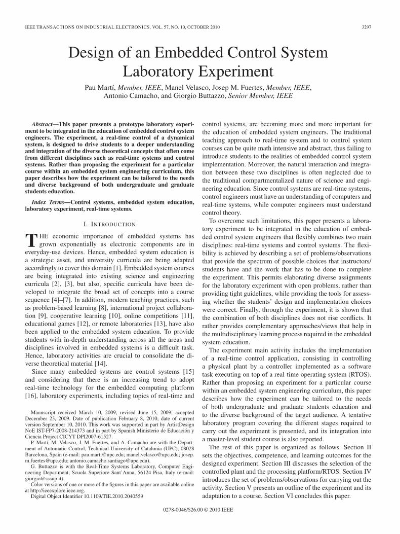
TABLE IREQUIRED SKILLS
TABLE IILEARNING OUTCOMES
II. OBJECTIVES, COMPETENCE,AND LEARNING OUTCOMES
The experiment objectives are twofold. First, the positivebenefits of experimental learning are well known in educationaland professional activities. Students’ confidence and enthusi-asm in experiments grow as they practice in problem solving,teamwork, design skills, etc. Second and more specifically,experiments should educate students in embedded control sys-tems, providing additional knowledge that they cannot acquirefrom theory.
Looking at the European Credit Transfer System, programobjectives are preferably specified in terms of the learning out-comes and competence to be acquired. Although the proposedexperiment is neither tailored to a specific program nor to anyspecific level of study (undergraduate and graduate), the mainskills to be acquired by students are listed in Table I. Skills 1and 2 relate to technical aspects and theoretical knowledge onembedded control systems; skills 3 and 4 relate to practicalissues and experimental learning, whereas skill 5 refers tosustainability issues. The multidisciplinary nature of embeddedsystems requires more background and transversal knowledgein different fields, combined with the capability of integratingdifferent skills for a system-wide objective. The learning out-comes are more specific because they state what is expectedfrom a student as a result of the learning process.
The learning outcomes are listed in Table II. The first threeoutcomes are related to understanding embedded control sys-tems, from a technical point of view, taking into account themultidisciplinary nature of the field. In this process, it is alsocrucial for students to be able to read, understand, and useexisting documentation, like datasheets, application program-ming interface (API) reference manuals, etc. Outcomes 4–6are related to implementation issues, which are essential forreproducing an experiment. Finally, the evaluation of sys-tem performance is crucial to assess if the specificationsare met.
The required background for students to carry out the ex-periments is a basic knowledge on control system theory andreal-time programming using an operating system.
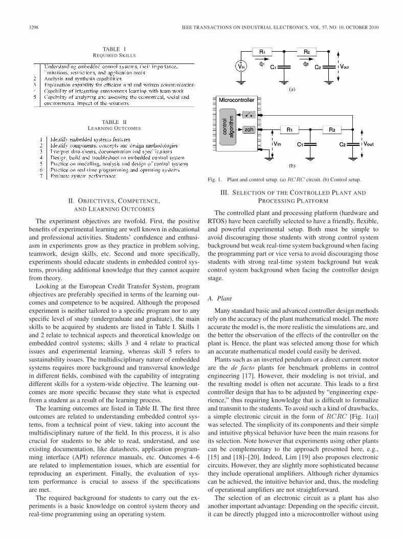
Fig. 1. Plant and control setup. (a) RCRC circuit. (b) Control setup.
III. SELECTION OF THE CONTROLLED PLANT AND
PROCESSING PLATFORM
The controlled plant and processing platform (hardware andRTOS) have been carefully selected to have a friendly, flexible,and powerful experimental setup. Both must be simple toavoid discouraging those students with strong control systembackground but weak real-time system background when facingthe programming part or vice versa to avoid discouraging thosestudents with strong real-time system background but weakcontrol system background when facing the controller designstage.
A. Plant
Many standard basic and advanced controller design methodsrely on the accuracy of the plant mathematical model. The moreaccurate the model is, the more realistic the simulations are, andthe better the observation of the effects of the controller on theplant is. Hence, the plant was selected among those for whichan accurate mathematical model could easily be derived.
Plants such as an inverted pendulum or a direct current motorare the de facto plants for benchmark problems in controlengineering [17]. However, their modeling is not trivial, andthe resulting model is often not accurate. This leads to a firstcontroller design that has to be adjusted by “engineering expe-rience,” thus requiring knowledge that is difficult to formalizeand transmit to the students. To avoid such a kind of drawbacks,a simple electronic circuit in the form of RCRC [Fig. 1(a)]was selected. The simplicity of its components and their simpleand intuitive physical behavior have been the main reasons forits selection. Note however that experiments using other plantscan be complementary to the approach presented here, e.g.,[15] and [18]–[20]. Indeed, Lim [19] also proposes electroniccircuits. However, they are slightly more sophisticated becausethey include operational amplifiers. Although richer dynamicscan be achieved, the intuitive behavior and, thus, the modelingof operational amplifiers are not straightforward.
The selection of an electronic circuit as a plant has alsoanother important advantage: Depending on the specific circuit,it can be directly plugged into a microcontroller without using
MARTÍ et al.: DESIGN OF AN EMBEDDED CONTROL SYSTEM LABORATORY EXPERIMENT 3299
intermediate electronic components, as shown in Fig. 1(b),where the zero-order hold (zoh) box represents the actu-ator and the box above represents the sampler, i.e., thetransistor–transistor logic level signals provided by the micro-controller can be enough to carry out the control. Note that thisis not the case, for example, for many mechanical systems. Sucha simplification in terms of hardware reduces the modelingeffort to study the plant, and no models for actuators or sensorsare required. Additional benefits of these types of plants arethat systems can be easily built, are cheap, have light weight,and can be easily transported and powered.
The control objective would be to have the circuit outputvoltage Vout (controlled variable) track a reference signal orsettle to a constant value while meeting, for example, the giventransient response specifications, which mandates using track-ing structures. The control will be achieved by sampling Vout,executing the control algorithm, and applying the calculatedcontrol signal to the circuit via varying the circuit input voltageVin (manipulated variable). Disturbances can be injected by avariable load voltage placed in parallel to the output voltage.
B. Processing Platform
The processing platform consists of the hardware platformand the RTOS. As a hardware platform, a microcontroller-based architecture was selected because embedded systemsare typically implemented using this type of hardware. Note,however, that too small microcontrollers may not be powerfulenough for running an RTOS, as discussed in [22]. Among theseveral possibilities available on the market [23], it was decidedto adopt the Flex board [24].
The Flex board (in its full version) represents a good com-promise between cost, processing power, and programmingflexibility. It was produced as a development board for buildingand testing real-time applications using standard componentsand open-source software. The board includes a MicrochipdsPIC digital signal microcontroller dsPIC33FJ256MC710, asocket for the 100-pin plug-in module, an in-circuit debugger(ICD2) programmer connector, a Universal Serial Bus con-nector for direct programming, power supply connectors, aset of LEDs for monitoring the board, an onboard MicrochipPIC18F2550 microcontroller for integrated programming, anda set of connectors for daughterboard piggybacking.
The board has several key benefits that make it suitable to beused for educational purposes. First, it has a robust electronicdesign, which is an important feature when it is employed bynonskilled users. Second, it has a modular architecture, whichallows users to easily develop homemade daughterboards usingstandard components. A set of daughterboards can be addedto the Flex board for easy development, such as a multibusboard equipped with a controller area network (CAN), Ethernet,I2C (Inter-Integrated Circuit), and other communication pro-tocols. On the one hand, the availability of CAN or Ethernetpermits building and experimenting with networked controlapplications. On the other hand, the available networks can beused for debugging purposes or for extracting data from theboard, which is a difficult task when dealing with embeddedsystems.
As far as the real-time kernel is concerned, different possibil-ities were considered. First, many well-known RTOSs, such asreal-time Linux [25], target processors that may be too powerfulfor embedded applications, but more importantly, their internalstructure is often too complex for those students with a lowprofile in (real-time) operating systems. Hence, it looks moredesirable to work with small real-time kernels (e.g., [26]–[31]for small real-time kernels targeting small architectures) whoseinternals are accessible and easy to understand and modify,in order to tailor them to the specific application needs. Onthe other hand, from a user point of view, programming andconfiguring the kernel (including creating tasks, assigning pri-orities/periods/deadlines, and setting the scheduling policy)should be friendly enough to attract nonskilled programmers.
From the considerations mentioned previously, an Erika En-terprise real-time kernel [24] was selected. Erika provides fullsupport to the Flex board in terms of drivers, libraries, program-ming facilities, and sample applications. The kernel, availableunder the General Public License and OSEK (Open Systemsand their Interfaces for the Electronics in Motor Vehicles [32])compliant, is an RTOS for small microcontrollers based on anAPI similar to those proposed by the OSEK consortium. Thekernel gives support for preemptive and nonpreemptive mul-titasking and implements several scheduling algorithms [33].The API provides support for tasks, events, alarms, resources,application modes, semaphores, and error handling. All thesefeatures permit enforcing real-time constraints to applicationtasks to show students the effects of sampling periods, delays,and jitter on control performance.
The development environment for Erika Enterprise is basedon cross compilation, avoiding typical student misconceptionswhen the development platform and the target share the samehardware. A tool, named RT-Druid [24] (based on Eclipse [34]),can be used as a default development platform to program inC, with support from Microchip for the compiler and for theprogramming development kit. The latter is important becauseMicrochip Web pages [35] are always a good place to shareexperiment experiences and code: a good place for instructorsand students to visit. RT-Druid implements an OSEK Imple-mentation Language (OIL) compiler, which is able to generatethe kernel configuration from an OIL specification. Apart fromprogramming in C, the Flex board can also be programmedautomatically using the Scilab/Scicos [36] code generator (sim-ilar to what can be done with MATLAB/Simulink [37] and itsReal-Time Workshop, as used, for example, in [38] for rapidcontrol prototyping). This is an important benefit for nonskilledC programmers.
From an education point of view, it is also important to notethat there is a possibility to build a community around thisprocessing platform to create a repository of control softwarefor education. In fact, a set of application notes that describe aset of control experiments (inverted pendulum, ball and plate,etc.) developed with Erika on Flex can be found in [24].
Finally, it must be stressed that the price of the Flex board liesin the lower bound of evaluation board prices and that the Erikakernel and the associated development tools are open source,available for free, or available for free in student edition format.Hence, it is an economically attractive option.
3300 IEEE TRANSACTIONS ON INDUSTRIAL ELECTRONICS, VOL. 57, NO. 10, OCTOBER 2010
IV. EXAMPLE OF THE LABORATORY EXPERIMENT
This section presents some of the activities in the form ofproblems and solutions (and observations) required to carry outthe laboratory experience, which are later ordered in the workplan. The emphasis is in the control analysis and design part.
A. Problem 1. Plant Modeling
If qi represents the charge on capacitor Ci, the differentialequations of the circuit, in terms of the currents qi at each Ri,are given by
q1R1 + (q1 − q2)1C1
= Vin
q2R2 + (q2 − q1)1C1
+ q21C2
= 0
q21C2
= Vout. (1)
For example, using state-space formalism, a state-space formis given by
x(t) =[
0 1−1
R1R2C1C2−R1C1+R2C2+R1C2
R1R2C1C2
]x(t)
+[
01
R1R2C1C2
]u(t)
y(t) = [ 1 0 ]x(t) (2)
where u(t) is the control signal, y(t) is the plant output, andx(t) = [x1 x2 ] is the state vector, where x1 corresponds tothe output voltage Vout and x2 is q2/C2.
Observation 1: The modeling of the plant could have beenalso done in terms of a transfer function (see [39] for theanalysis). Even obtaining the differential equations is a goodexercise. Adopting the state-space formalism may add anotherbenefit if using (2). Since only the output voltage x1 can bephysically measured, the control algorithm requires the use ofobservers for predicting x2. This opens the door to experiment-ing with several types of observers, and the implementation ofthe controller has to include them. Furthermore, the selectionof the state variables is arbitrary, and therefore, students haveto take design decisions. For example, the voltages in bothcapacitors could also have been chosen as state variables. In anycase, if possible, it is interesting to choose the state variablesin such a way that the controlled variable is directly availablethrough the output matrix in order to minimize computations inthe microcontroller.
B. Problem 2. Electronic Components
The selection of the electronic components is very impor-tant for several reasons. The output impedance must be lowenough to properly connect the circuit to the analog-to-digitalconverter (ADC) or to some external instrumentation, suchas an oscilloscope. For example, given the initial componentsR1 = R2 = 1 kΩ and C1 = C2 = 33 μF, a manageable circuit
impedance is obtained. With these components, the state-spacemodel becomes
x(t) =[
0 1−976.56 −93.75
]x(t) +
[0
976.56
]u(t)
y(t) = [ 1 0 ]x(t). (3)
Observation 2: Students can be given other values. Forexample, with R1 = R2 = 330 kΩ and C1 = C2 = 100 nF, it iseasy to see that the equivalent output impedance is too high forthe ADC. To derive such a conclusion, students have to consultthe dsPIC datasheet.
C. Problem 3. Open-Loop Simulation
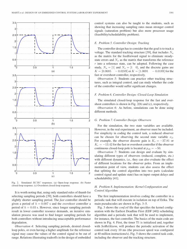
Open-loop dynamics can be observed by injecting referencesignals to the circuit via its input Vin. For example, by injectinga square wave that oscillates between 1 and 2.5 V at 1 Hz, theobtained dynamics are shown in Fig. 2(a). The voltage outputVout (solid curve) slowly tracks the reference (dashed curve).
Observation 3: The electronic components determine thecircuit open-loop dynamics. Students must be aware of this byplaying with different electronic components. In addition, sim-ulation can be done by standard software packages used in con-trol engineering (e.g., MATLAB/Simulink and Scilab/Scicos)or by programming the response in C or even using a spread-sheet application.
D. Problem 4. Controller Design: Sampling Period andPerformance Specifications
For the chosen plant, there can be different control goals.A possibility can be to modify the RCRC transient responseby accelerating it or by arbitrarily achieving a given overshoot.In any case, the selection of the sampling period and the con-troller itself have a strong impact on the control performance.Furthermore, they have to be selected and designed takinginto account the processing platform. If avoiding intermediateelectronics between the plant and dsPIC is the assumption, thecontrol signal (Vin) can be generated using pulsewidth modu-lation [(PWM); by adjusting the duty cycle], and the controlledvariable (Vout) can be obtained through the ADC. Therefore,the reference, the sampling period, and the controller must bechosen/designed so that the voltage levels of the control signaland the generated peak current levels lie within the hardwarelimitations.
Given the previous square reference signal, through an itera-tive design stage, and according to standard rules of thumb, twostate feedback controllers can be designed: one that acceleratesthe response, named fast controller, and another that producesovershoot, named overshoot controller. For the fast controller,the period is set to h = 0.01 s, and the discrete state feedbackcontroller is designed to place the continuous closed-loop polesat p1,2 = −30 (note that the open-loop system has poles at−12 and −81 approximately). The overshoot controller hasa sampling period of h = 0.1 s, and the controller places theclosed-loop poles at p1,2 = −10 ± 20i.
MARTÍ et al.: DESIGN OF AN EMBEDDED CONTROL SYSTEM LABORATORY EXPERIMENT 3301
Fig. 2. Simulated RCRC responses. (a) Open-loop response. (b) Fasterclosed-loop response. (c) Overshoot closed-loop response.
It is worth noting that, using only standard rules of thumb forselecting sampling periods [39], both controllers should have aslightly shorter sampling period. The fast controller should begiven a period of h = 0.007 s and the overshoot controller aperiod of h = 0.03 s. However, since longer sampling periodsresult in lower controller resource demands, an iterative sim-ulation process was used to find longer sampling periods forboth controllers without introducing unacceptable performancedegradation.
Observation 4: Selecting sampling periods, desired closed-loop poles, or even having a higher amplitude for the referencesignal may cause the values of the control signal to be out ofrange. Relations illustrating tradeoffs in the design of embedded
control systems can also be taught to the students, such asshowing that increasing sampling rates mean stronger controlsignals (saturation problem) but also more processor usage(feasibility/schedulability problem).
E. Problem 5. Controller Design: Tracking
The controller design has to consider that the goal is to track avoltage. The standard tracking structure [39], that includes Nu
as the matrix for the feedforward signal to eliminate steady-state errors and Nx as the matrix that transforms the referencer into a reference state, can be adopted. Following the casestudy, Nu = [1] and Nx = [1 0], and the discrete gains areK = [0.0685 − 0.0249] or K = [1.0691 − 0.0189] for thefast or overshoot controller, respectively.
Observation 5: Students can practice other tracking struc-tures, such as integral control, and can study whether the codeof the controller would suffer significant changes.
F. Problem 6. Controller Design: Closed-Loop Simulation
The simulated closed-loop response for the fast and over-shoot controllers is shown in Fig. 2(b) and (c), respectively.
Observation 6: As before, simulations can be done usingdifferent methods.
G. Problem 7. Controller Design: Observers
For the simulation, the two state variables are available.However, in the real experiment, an observer must be included.For simplicity in coding the control task, a reduced observercan be chosen for observing the second state variable x2.For example, the observer discrete gain is Kr = −37.81 orKr = −13.42 for the fast or overshoot controller if the observercontinuous closed-loop pole is located at pob = −50.
Observation 7: Students can design and evaluate by sim-ulating different types of observers (reduced, complete, etc.)with different dynamics, i.e., they can also evaluate the effectof different locations for the observer poles. From an imple-mentation point of view, students can also assess the effectthat splitting the control algorithm into two parts (calculatecontrol signal and update state) has on input–output delays andschedulability [41].
H. Problem 8. Implementation: Kernel Configuration andControl Algorithm
The first implementation involves coding the controller in aperiodic task that will execute in isolation on top of Erika. Themain pseudocodes are shown in Figs. 3–5.
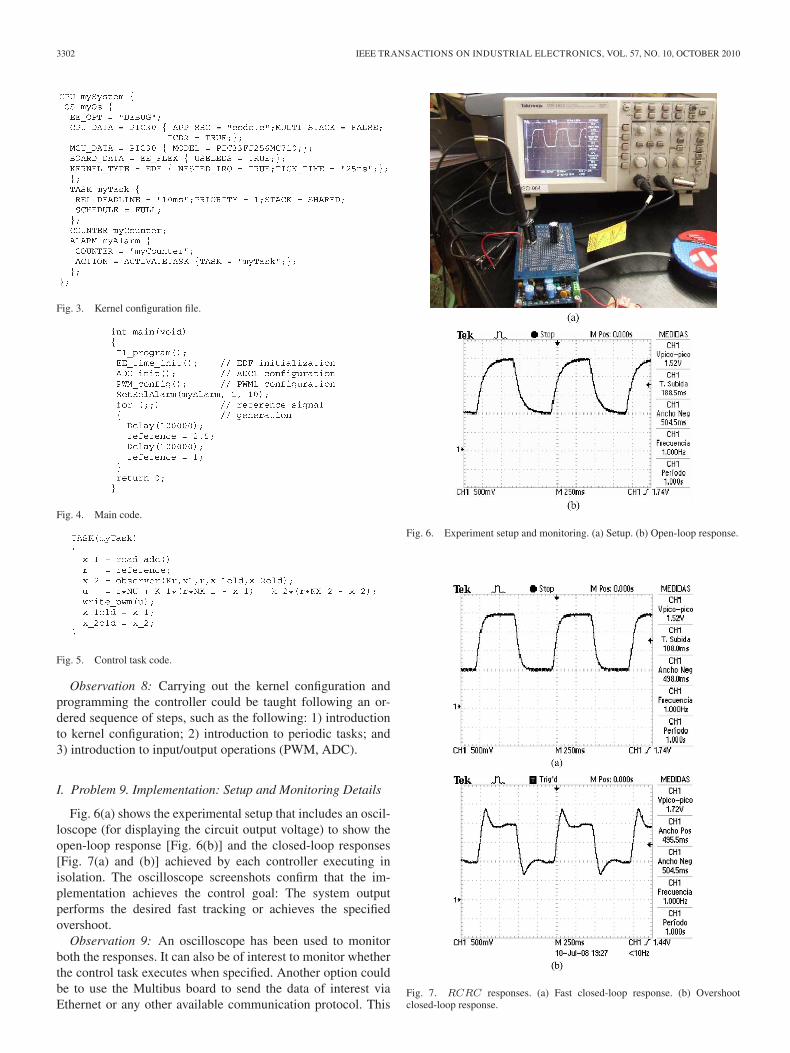
Fig. 3 shows the conf.oil file that specifies the kernel config-uration with the Earliest Deadline First (EDF [40]) schedulingalgorithm and a periodic task that will be used to implement,for instance, the fast controller. The basics of the main code areshown in Fig. 4. First, the timer T1 is initialized and, togetherwith SetRelAlarm, will produce the periodic activation of thecontrol task every 10 ms (the processor speed was configuredat 40 million instructions/s). Fig. 5 shows the control task code,including the observer and the tracking structure.
3302 IEEE TRANSACTIONS ON INDUSTRIAL ELECTRONICS, VOL. 57, NO. 10, OCTOBER 2010
Fig. 3. Kernel configuration file.
Fig. 4. Main code.
Fig. 5. Control task code.
Observation 8: Carrying out the kernel configuration andprogramming the controller could be taught following an or-dered sequence of steps, such as the following: 1) introductionto kernel configuration; 2) introduction to periodic tasks; and3) introduction to input/output operations (PWM, ADC).
I. Problem 9. Implementation: Setup and Monitoring Details
Fig. 6(a) shows the experimental setup that includes an oscil-loscope (for displaying the circuit output voltage) to show theopen-loop response [Fig. 6(b)] and the closed-loop responses[Fig. 7(a) and (b)] achieved by each controller executing inisolation. The oscilloscope screenshots confirm that the im-plementation achieves the control goal: The system outputperforms the desired fast tracking or achieves the specifiedovershoot.
Observation 9: An oscilloscope has been used to monitorboth the responses. It can also be of interest to monitor whetherthe control task executes when specified. Another option couldbe to use the Multibus board to send the data of interest viaEthernet or any other available communication protocol. This
Fig. 6. Experiment setup and monitoring. (a) Setup. (b) Open-loop response.
Fig. 7. RCRC responses. (a) Fast closed-loop response. (b) Overshootclosed-loop response.
MARTÍ et al.: DESIGN OF AN EMBEDDED CONTROL SYSTEM LABORATORY EXPERIMENT 3303
would pose interesting challenges in terms of the real-timesystem such as noninvasive debugging.
J. Problem 10. Multitasking: Simulation
A second implementation is introduced to illustrate more ad-vanced concepts. In the previous implementation, a control taskwas executing in isolation. However, in many high-technologysystems, the processor is used not only for the control com-putation but also for interrupt handling, error management,monitoring, etc. Furthermore, it is known that, in multitaskingreal-time control systems, jitters, i.e., timing interferences oncontrol tasks due to the concurrent execution of other tasks,deteriorate the control loop performance [41]. The objective ofthis implementation is to observe these degrading effects andimplement corrective actions, e.g., [42]–[44].
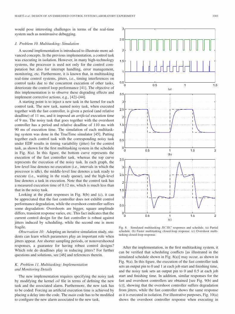
A starting point is to inject a new task in the kernel for eachcontrol task. The new task, named noisy task, when executedtogether with the fast controller, is given a period (and relativedeadline) of 11 ms, and it imposed an artificial execution timeof 9 ms. The noisy task that goes together with the overshootcontroller has a period and relative deadline of 110 ms with90 ms of execution time. The simulation of each multitask-ing system was done in the TrueTime simulator [45]. Puttingtogether each control task with the corresponding noisy taskunder EDF results in timing variability (jitter) for the controltask, as shown for the first multitasking system in the schedulein Fig. 8(a). In this figure, the bottom curve represents theexecution of the fast controller task, whereas the top curverepresents the execution of the noisy task. In each graph, thelow-level line denotes no execution (i.e., intervals in which theprocessor is idle), the middle-level line denotes a task ready toexecute (i.e., waiting in the ready queue), and the high-levelline denotes a task in execution. Note that the control task hasa measured execution time of 0.12 ms, which is much less thanthat in the noisy task.
Looking at the plant responses in Fig. 8(b) and (c), it canbe appreciated that the fast controller does not exhibit controlperformance degradation, while the overshoot controller sufferssome degradation: Overshoots are bigger, square amplitudediffers, transient response varies, etc. This fact indicates that thecurrent control design for the fast controller is robust againstjitters induced by scheduling, while the second one is morefragile.
Observation 10: Adopting an iterative simulation study, stu-dents can learn which parameters play an important role whenjitters appear. Are shorter sampling periods, or nonovershootedresponses, a guarantee for having robust control designs?Which role do deadlines play in reducing jitters? For furtherquestions and solutions, see [46] and references therein.
K. Problem 11. Multitasking: Implementationand Monitoring Details
The new implementation requires specifying the noisy taskby modifying the kernel oil file in terms of defining the newtask and the associated alarm. Furthermore, the new task hasto be coded: Forcing an artificial execution time is achieved byplacing a delay into the code. The main code has to be modifiedto configure the new alarm associated to the new task.
Fig. 8. Simulated multitasking RCRC responses and schedule. (a) Partialschedule. (b) Faster multitasking closed-loop response. (c) Overshoot multi-tasking closed-loop response.
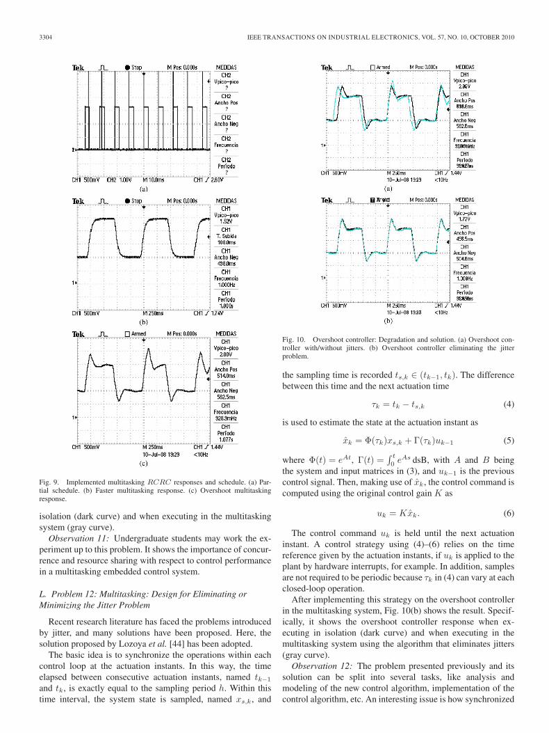
After the implementation, in the first multitasking system, itcan be verified that scheduling conflicts [as illustrated in thesimulated schedule shown in Fig. 8(a)] may occur, as shown inFig. 9(a). In this figure, the execution of the fast controller tasksets an output pin to 0 and 1 at each job start and finishing time,and the noisy task sets an output pin to 0 and 0.5 at each jobstart and finishing time. In addition, similar responses for thefast and overshoot controllers are obtained [see Fig. 9(b) and(c)], showing that the overshoot controller suffers degradationfrom jitters, while the fast controller shows the same responseas it is executed in isolation. For illustrative purposes, Fig. 10(a)shows the overshoot controller response when executing in
3304 IEEE TRANSACTIONS ON INDUSTRIAL ELECTRONICS, VOL. 57, NO. 10, OCTOBER 2010
Fig. 9. Implemented multitasking RCRC responses and schedule. (a) Par-tial schedule. (b) Faster multitasking response. (c) Overshoot multitaskingresponse.
isolation (dark curve) and when executing in the multitaskingsystem (gray curve).
Observation 11: Undergraduate students may work the ex-periment up to this problem. It shows the importance of concur-rence and resource sharing with respect to control performancein a multitasking embedded control system.
L. Problem 12: Multitasking: Design for Eliminating orMinimizing the Jitter Problem
Recent research literature has faced the problems introducedby jitter, and many solutions have been proposed. Here, thesolution proposed by Lozoya et al. [44] has been adopted.
The basic idea is to synchronize the operations within eachcontrol loop at the actuation instants. In this way, the timeelapsed between consecutive actuation instants, named tk−1
and tk, is exactly equal to the sampling period h. Within thistime interval, the system state is sampled, named xs,k, and
Fig. 10. Overshoot controller: Degradation and solution. (a) Overshoot con-troller with/without jitters. (b) Overshoot controller eliminating the jitterproblem.
the sampling time is recorded ts,k ∈ (tk−1, tk). The differencebetween this time and the next actuation time
τk = tk − ts,k (4)
is used to estimate the state at the actuation instant as
xk = Φ(τk)xs,k + Γ(τk)uk−1 (5)
where Φ(t) = eAt, Γ(t) =∫ t
0 eAs dsB, with A and B beingthe system and input matrices in (3), and uk−1 is the previouscontrol signal. Then, making use of xk, the control command iscomputed using the original control gain K as
uk = Kxk. (6)
The control command uk is held until the next actuationinstant. A control strategy using (4)–(6) relies on the timereference given by the actuation instants, if uk is applied to theplant by hardware interrupts, for example. In addition, samplesare not required to be periodic because τk in (4) can vary at eachclosed-loop operation.
After implementing this strategy on the overshoot controllerin the multitasking system, Fig. 10(b) shows the result. Specif-ically, it shows the overshoot controller response when ex-ecuting in isolation (dark curve) and when executing in themultitasking system using the algorithm that eliminates jitters(gray curve).
Observation 12: The problem presented previously and itssolution can be split into several tasks, like analysis andmodeling of the new control algorithm, implementation of thecontrol algorithm, etc. An interesting issue is how synchronized
MARTÍ et al.: DESIGN OF AN EMBEDDED CONTROL SYSTEM LABORATORY EXPERIMENT 3305
actuation instants can be forced in the kernel. For example,a solution could be to use a periodic task for computing uk
and another periodic task for applying uk at the required time.Another solution could be to enforce synchronized executionsat the kernel level, using the EDF tick counter. Moreover, sincedifferent solutions to the jitter problem, such as that in [42]or [43], could have also been applied, students that are moreconfident or interested in specific fields can select the solutionthat better meets their preferences.
V. TENTATIVE WORK PLAN AND ITS APPLICATION
TO A SPECIFIC COURSE
The previous section has detailed some of the steps requiredto successfully carry out the laboratory activity presented inthis paper. This section summarizes them in order to proposea tentative work plan that is divided into several sessions, witheach one being a 2-h laboratory.
1) S1-Introduction: Introduction to the activity and sim-ulation of the open-loop response after obtaining thestate-space form of the RCRC circuit from the circuitdifferential equations (1) (consider random values for Rand C). Here, it is assumed that a state-space notation ischosen.
2) S2-Problem specification (a): This session should beused to specify the problem in terms of the levels forthe reference signal and for the discrete controller design,which includes selecting the sampling period and theclosed-loop pole locations, if pole placement is used.Other control approaches, like optimal control, could alsobe used.
3) S3-Problem specification (b): To complement the pre-vious session, observers should also be designed andsimulated. The outcome of this session should be thecomplete simulation setup.
4) S4-Basic implementation (a): Build the RCRC circuitand verify its dynamics in open loop. Start the controllerimplementation in a periodic hard real-time task in theprocessing platform.
5) S5-Basic implementation (b): Finish the controller im-plementation and test its correctness.
6) S6-Multitasking (a): Incorporate a noisy task in thesimulation setup to evaluate the effects of jitter. Thisstep would require using, for example, the TrueTimesimulator.
7) S7-Multitasking (b): Incorporate the noisy task in theimplementation and validate the previous simulationresults.
8) S8-Advanced implementation (a): If degradation incontrol performance is detected in the previous session,simulate advanced control algorithms or adopt real-timetechniques to solve or reduce the jitter problem.
9) S9-Advanced implementation (b): Implement the pre-vious solutions and validate them.
Note that the program timing, the layout, and the set ofcovered topics should be adapted to the particular needs/background of the target audience or to the goals of a spe-cific curriculum. For example, the proposed activity has been
introduced as part of the curriculum of the two-year masterdegree on Automatic Control and Industrial Electronics in theSchool of Engineering of Vilanova i la Geltrú (EPSEVG) ofthe Technical University of Catalonia (UPC) [47]. In particular,since 2007, the experiment has been tailored to become part ofthe laboratory for the Control Engineering course, which coverscontinuous and discrete linear time-invariant (LTI) control sys-tems, as well as nonlinear control systems, all using state-spaceformalism. Sessions S1–S5 were adopted for the laboratory ofthe discrete LTI control system part.
The Control Engineering course can be followed by studentseither in the first semester of the first year or in the first semesterof the second year. Students choosing the second option si-multaneously attend a course on real-time systems. Therefore,within the same classroom, not all the students are familiar withreal-time systems. To overcome this apparent drawback, teamsof three students were formed containing at least a student withcompetence on real-time systems. Within such heterogeneousteams in terms of skills and theoretical background, it wasobserved that students took their responsibilities, and teamworkwas significantly improved.
As in every course edition, after finishing the discrete LTIcontrol system part, a short and simple questionnaire is givento the students to let them evaluate several aspects of thispart of the course. The question Do the laboratory activitiespermit to better understand the theoretical concepts? is theonly one related to the laboratories. Looking at the students’answers and taking into account that, before introducing thepresented experiment, the laboratory activities were focused onthe simulation of an inverted pendulum, the percentage of stu-dents appreciating the practical part has increased significantly.Although the standard course evaluation indicates this positivetrend, a more complete evaluation tailored to the introductionof this experiment is required.
VI. CONCLUSION
This paper has presented a laboratory activity to be integratedin the education curriculum of embedded control system en-gineers. The activity consists of a real-time controller of anRCRC electronic circuit. The potential benefits, the compe-tences to be acquired, and the expected learning outcomes forstudents have been presented. The selection of the plant andprocessing platform has been discussed. Extensive details ofa sample implementation have been presented, and a tentativework plan for carrying out the activity has been provided.
In summary, the proposed activity poses several real chal-lenges to the students that can be met by putting togetherinterdisciplinary skills (electronics, real-time systems, controltheory, and programming) toward a single goal: building aworking system.
REFERENCES
[1] D. J. Jackson and P. Caspi, “Embedded systems education: Future direc-tions, initiatives, and cooperation,” SIGBED Rev., vol. 2, no. 4, pp. 1–4,Oct. 2005.
[2] A. Crespo, J. Vila, F. Blanes, and I. Ripoll, “Real-time education in acontrol engineering curriculum,” in Proc. 3rd IEEE Real-Time Syst. Educ.Workshop, 1998, pp. 112–116.
3306 IEEE TRANSACTIONS ON INDUSTRIAL ELECTRONICS, VOL. 57, NO. 10, OCTOBER 2010
[3] K. G. Ricks, D. J. Jackson, and W. A. Stapleton, “Incorporating embeddedprogramming skills into an ECE curriculum,” SIGBED Rev., vol. 4, no. 1,pp. 17–26, Jan. 2007.
[4] W. A. Halang, “A curriculum for real-time computer and control systemsengineering,” IEEE Trans. Educ., vol. 33, no. 2, pp. 171–178, May 1990.
[5] P. Caspi, A. Sangiovanni-Vincentelli, L. Almeida, A. Benveniste,B. Bouyssounouse, G. Buttazzo, I. Crnkovic, W. Damm, J. Engblom,G. Folher, M. Garcia-Valls, H. Kopetz, Y. Lakhnech, F. Laroussinie,L. Lavagno, G. Lipari, F. Maraninchi, P. Peti, J. de la Puente, N. Scaife,J. Sifakis, R. de Simone, M. Torngren, P. Veríssimo, A. J. Wellings,R. Wilhelm, T. Willemse, and W. Yi, “Guidelines for a graduate curricu-lum on embedded software and systems,” ACM Trans. Embed. Comput.Syst., vol. 4, no. 3, pp. 587–611, Aug. 2005.
[6] A. Sangiovanni-Vincentelli and A. Pinto, “An overview of embeddedsystem design education at Berkeley,” ACM Trans. Embed. Comput. Syst.,vol. 4, no. 3, pp. 472–499, Aug. 2005.
[7] K. G. Ricks, D. J. Jackson, and W. A. Stapleton, “An embedded systemscurriculum based on the IEEE/ACM model curriculum,” IEEE Trans.Educ., vol. 51, no. 2, pp. 262–270, May 2008.
[8] D. Davcev, B. Stojkoska, S. Kalajdziski, and K. Trivodaliev, “Projectbased learning of embedded systems,” in Proc. 2nd WSEAS Int. Conf.Circuits, Syst., Signal Telecommun., 2008, pp. 120–125.
[9] S. Nooshabadi and J. Garside, “Modernization of teaching in embeddedsystems design—An international collaborative project,” IEEE Trans.Educ., vol. 49, no. 2, pp. 254–262, May 2006.
[10] J. W. Bruce, J. C. Harden, and R. B. Reese, “Cooperative and progressivedesign experience for embedded systems,” IEEE Trans. Educ., vol. 47,no. 1, pp. 83–92, Feb. 2004.
[11] J. Fernandez, R. Marin, and R. Wirz, “Online competitions: An open spaceto improve the learning process,” IEEE Trans. Ind. Electron., vol. 54,no. 6, pp. 3086–3093, Dec. 2007.
[12] U. Munz, P. Schumm, A. Wiesebrock, and F. Allgower, “Motivation andlearning progress through educational games,” IEEE Trans. Ind. Electron.,vol. 54, no. 6, pp. 3141–3144, Dec. 2007.
[13] L. Gomes and S. Bogosyan, “Current trends in remote laboratories,” IEEETrans. Ind. Electron., vol. 56, no. 12, pp. 4744–4756, Dec. 2009.
[14] D. T. Rover, R. A. Mercado, Z. Zhang, M. C. Shelley, and D. S. Helvick,“Reflections on teaching and learning in an advanced undergraduatecourse in embedded systems,” IEEE Trans. Educ., vol. 51, no. 3, pp. 400–412, Aug. 2008.
[15] K.-E. Årzén, A. Blomdell, and B. Wittenmark, “Laboratories and real-time computing: Integrating experiments into control courses,” IEEEControl Syst. Mag., vol. 25, no. 1, pp. 30–34, Feb. 2005.
[16] G. Buttazzo, “Research trends in real-time computing for embedded sys-tems,” ACM SIGBED Rev., vol. 3, no. 3, pp. 1–10, Jul. 2006.
[17] P. Horacek, “Laboratory experiments for control theory courses: A sur-vey,” Annu. Rev. Control, vol. 24, pp. 151–162, 2000.
[18] M. Moallem, “A laboratory testbed for embedded computercontrol,” IEEE Trans. Educ., vol. 47, no. 3, pp. 340–347,Aug. 2004.
[19] D.-J. Lim, “A laboratory course in real-time software for the controlof dynamic systems,” IEEE Trans. Educ., vol. 49, no. 3, pp. 346–354,Aug. 2006.
[20] M. Huba and M. Simunek, “Modular approach to teaching PID con-trol,” IEEE Trans. Ind. Electron., vol. 54, no. 6, pp. 3112–3121,Dec. 2007.
[21] VxWorks Operating System from WindRiver. [Online]. Available:http://www.windriver.com/
[22] R. Marau, P. Leite, M. Velasco, P. Martí, L. Almeida, P. Pedreiras, andJ. M. Fuertes, “Performing flexible control on low cost microcontrollersusing a minimal real-time kernel,” IEEE Trans. Ind. Informat., vol. 4,no. 2, pp. 125–133, May 2008.
[23] F. Salewski, D. Wilking, and S. Kowalewski, “Diverse hardware plat-forms in embedded systems lab courses: A way to teach the differences,”SIGBED Rev., vol. 2, no. 4, pp. 70–74, Oct. 2005.
[24] Evidence srl. [Online]. Available: http://www.evidence.eu.com/[25] Real-time Linux Found., Inc. [Online]. Available: http://www.
realtimelinuxfoundation.org/[26] J. A. Stankovic and K. Ramamritham, “The spring kernel: A new para-
digm for real-time operating systems,” SIGOPS Oper. Syst. Rev., vol. 23,no. 3, pp. 54–71, Jul. 1989.
[27] K. M. Zuberi, P. Pillai, and K. G. Shin, “Emeralds: A small-memory real-time microkernel,” in Proc. 7th ACM Symp. Oper. Syst. Principles, 1999,pp. 277–299.
[28] P. Gai, G. Lipari, L. Abeni, M. di Natale, and E. Bini, “Architec-ture for a portable open source real-time kernel environment,” inProc. 2nd Real-Time Linux Workshop/Hand’s On Real-Time Linux Tu-
torial, Nov. 2000, 9 pages. [Online]. Available: http://www.osadl.org/RTLWS-2000.rtlws-2000.0.html
[29] E. Mumolo, M. Nolich, and M. Noser, “A hard real-time kernel for Mo-torola microcontrollers,” in Proc. 23rd Int. Conf. Inf. Technol. Interfaces,Jun. 2001, pp. 75–80.
[30] P. Gai, L. Abeni, M. Giorgi, and G. Buttazzo, “A new kernel approach formodular real-time systems development,” in Proc. 13th IEEE EuromicroConf. Real-Time Syst., Jun. 2001, pp. 199–206.
[31] D. Henriksson and A. Cervin, “Multirate feedback control using theTinyRealTime kernel,” in Proc. 19th Int. Symp. Comput. Inf. Sci., Antalya,Turkey, Oct. 2004, pp. 855–865.
[32] OSEK/VDX Portal. [Online]. Available: http://www.osek-vdx.org/[33] G. Buttanzo, Hard Real-Time Computing Systems: Predictable Schedul-
ing Algorithms and Applications. Norwell, MA: Kluwer, 1997.[34] Eclipse Portal. [Online]. Available: http://www.eclipse.org/[35] Microchip Portal. [Online]. Available: http://www.microchip.com/[36] Scilab/Scicos Portal. [Online]. Available: http://www.scilab.org/[37] MathWorks Portal. [Online]. Available: http://www.mathworks.com/[38] D. Hercog, B. Gergic, S. Uran, and K. Jezernik, “A DSP-based remote
control laboratory,” IEEE Trans. Ind. Electron., vol. 54, no. 6, pp. 3057–3068, Dec. 2007.
[39] K. Ogata, Modern Control Engineering, 4th ed. Englewood Cliffs, NJ:Prentice-Hall, 2001.
[40] C. L. Liu and J. W. Layland, “Scheduling algorithms for multiprogram-ming in a hard-real-time environment,” J. Assoc. Comput. Machinery,vol. 20, no. 1, pp. 46–61, Jan. 1973.
[41] K.-E. Årzén, A. Cervin, J. Eker, and L. Sha, “An introduction to controland scheduling co-design,” in Proc. 39th IEEE Conf. Decision Control,2000, pp. 4865–4870.
[42] J. Skaf and S. Boyd, “Analysis and synthesis of state-feedback controllerswith timing jitter,” IEEE Trans. Autom. Control, vol. 54, no. 3, pp. 652–657, Mar. 2009.
[43] P. Balbastre, I. Ripoll, J. Vidal, and A. Crespo, “A task model to reducecontrol delays,” Real-Time Syst., vol. 27, no. 3, pp. 215–236, Sep. 2004.
[44] C. Lozoya, M. Velasco, and P. Martí, “The one-shot task model for robustreal-time embedded control systems,” IEEE Trans. Ind. Informat., vol. 4,no. 3, pp. 164–174, Aug. 2008.
[45] D. Henriksson, A. Cervin, and K.-E. Årzén, “TrueTime: Simulationof control loops under shared computer resources,” in Proc. 15thIFACWorld Congr., 2002, 7 pages. [Online]. Available: http://www.ifac-papersonline.net/Detailed/26606.html
[46] Y. Wu, E. Bini, and G. Buttazzo, “A framework for designing embeddedreal-time controllers,” in Proc. 14th IEEE Int. Conf. Embed. Real-TimeComput. Syst. Appl., Aug. 2008, pp. 303–311.
[47] EPSEVG School Portal. [Online]. Available: http://www.epsevg.upc.edu/
Pau Martí (M’02) received the B.S. degree in com-puter science and the Ph.D. degree in automaticcontrol from the Technical University of Catalonia(UPC), Barcelona, Spain, in 1996 and 2002,respectively.
Since 1996, he has been an Assistant Professorwith the Department of Automatic Control, UPC.During his Ph.D., he was a Visiting Student atMälardalen University, Västerås, Sweden. From2003 to 2004, he was a Research Fellow with theComputer Science Department, University of
California, Santa Cruz. His research interests include embedded systems,control systems, real-time systems, and communication systems.
Manel Velasco received the B.S. degree in mar-itime engineering and the Ph.D. degree in automaticcontrol from the Technical University of Catalonia(UPC), Barcelona, Spain, in 1999 and 2006,respectively.
Since 2002, he has been an Assistant Professorwith the Department of Automatic Control, UPC.His research interests include artificial intelligence,real-time control systems, and collaborative controlsystems, particularly on redundant controllers andmultiple controllers with self-interacting systems.
MARTÍ et al.: DESIGN OF AN EMBEDDED CONTROL SYSTEM LABORATORY EXPERIMENT 3307
Josep M. Fuertes (S’74–M’96) received the B.S.degree in industrial engineering and the Ph.D. degreefrom the Technical University of Catalonia (UPC),Barcelona, Spain, in 1976 and 1986, respectively.
From 1975 to 1986, he was a Researcher with theInstitut de Cibernética (Spanish Consejo Superior deInvestigaciones Científicas). In 1987, he became aPermanent Professor with UPC. In 1987, he got aposition for a year at the Ernest Orlando LawrenceBerkeley National Laboratory, Berkeley, CA, wherehe was a Visiting Scientific Fellow for the design
of the Active Control System of the W. M. Keck 10-m segmented telescope(Hawaii). In 1992, he was responsible of the University Research Line inAdvanced Control Systems and, later, of the Distributed Control SystemsGroup. From 1996 to 2001, he acted as a Spanish Representative at theCouncil of the European Union Control Association. He is currently with theDepartment of Automatic Control, UPC. His research interests are in the areasof distributed, networked, and real-time control systems and applications. Since1989, he has been coordinating projects at the national and international levelsrelated to the aforementioned areas of expertise.
Dr. Fuertes is a member of the Administrative Committee of the IEEEIndustrial Electronics Society, where he is the Chair of the Technical Committeeon Networked-Based Control Systems and Applications. He has collaborated asthe Organizer, the Chairman, the Session Organizer, and a member of programcommittees for several international conferences.
Antonio Camacho received the B.S. degree inchemical engineering and the M.S. degree in automa-tion and industrial electronics from the TechnicalUniversity of Catalonia, Barcelona, Spain, in 2000and 2009, respectively, where he is currently workingtoward the Ph.D. degree in electronic engineering.
His research interests include networked and em-bedded control systems, industrial informatics, andpower electronics.
Giorgio Buttazzo (SM’05) received the B.S. de-gree in electronic engineering from the University ofPisa, Pisa, Italy, in 1985, the M.S. degree in com-puter science from the University of Pennsylvania,Philadelphia, in 1987, and the Ph.D. degree in com-puter engineering from Scuola Superiore Sant’Anna,Pisa, in 1991.
From 1987 to 1988, he was with the General Ro-botics, Automation, Sensing and Perception Labora-tory, University of Pennsylvania, where he workedon active perception and real-time control. He is
currently a Full Professor of computer engineering with Scuola Superi-ore Sant’Anna. He has authored six books on real-time systems and over200 papers in the field of real-time systems, robotics, and neural networks. Hismain research interests include real-time operating systems, dynamic schedul-ing algorithms, quality-of-service control, multimedia systems, advanced ro-botics applications, and neural networks.