Embed Size (px)
Citation preview
This journal is© the Owner Societies 2017 Phys. Chem. Chem. Phys., 2017, 19, 29187--29194 | 29187
Cite this:Phys.Chem.Chem.Phys.,
2017, 19, 29187
Design of an efficient coherent multi-sitesingle-molecule rectifier†
Mickael L. Perrin, ab Matthijs Doelman,a Rienk Eelkema c andHerre S. J. van der Zant *a
We propose the design of a single-molecule diode with a rectification ratio exceeding a million.
The employed mechanism is based on coherent resonant charge transport across a molecule that
consists of four conjugated sites coupled by non-conjugated bridges. Using density functional theory
calculations, we rationalize the design of the molecule and demonstrate the crucial role of aligning the
sites at a specific voltage. Rectification ratios are calculated for a series of chemical substituents and
demonstrate that with careful molecular design, high rectification ratios can be achieved. Finally, we
comment on the shortcomings of our approach, how further improvements can be obtained and
discuss some of the experimental challenges.
Molecular diodes have been attracting much attention recently,both in self-assembled monolayers1–7 and on the single-moleculescale.8–16 Even though the rectifier has been the seminal devicewhich launched the field of single-molecule electronics,17 up todate, their performance have many shortcomings. In particular,their rectification ratios (RR) are orders of magnitude lower thantypical semiconducting rectifiers. The highest RR reported experi-mentally on a single-molecule junction15 is about 600, and is nomatch for a semiconducting diode where ratios exceeding 106 arecommon. In that study, a molecular backbone was consideredwhich consisted of two identical, weakly-coupled conjugatedparts. In such a system, current flows coherently when bothhalves are on resonance, i.e., the sites are aligned with eachother within the bias window. The alignment of the two sitescan be modified by applying a bias voltage and/or by chemicalsubstituents. With proper design, one can align the sites at zerobias, while misaligning them at finite bias, yielding negativedifferential conductance.18 One can also align the sites at afinite bias,15,19–22 and achieve single-molecule rectification.
Based on a similar principle, here we investigate theoreti-cally how the rectification ratio of single-molecule diodes can
be significantly enhanced by the addition of more sites inseries, as shown in as presented in Fig. 1b. Low RR areprimarily caused by a high reverse current. Adding more sitesin series leads to a strong suppression of the reverse current,thereby drastically improving the RR. However, the addi-tion of sites comes at the cost of an increased molecularcomplexity and number of model parameters. In this study,we first focus on the design of a molecule which behaves ashaving four sites in series. For this purpose, we use densityfunctional theory (DFT) calculations. We then investigate howthe molecule can be engineered by the means of chemicalsubstitution to align the sites at a particular bias voltage.We eventually show that the molecule designed with foursites represents a drastic improvement compared to a two-sitemolecule, with RR approaching 106, competitive with silicon-based diodes.
1 Design guidelines
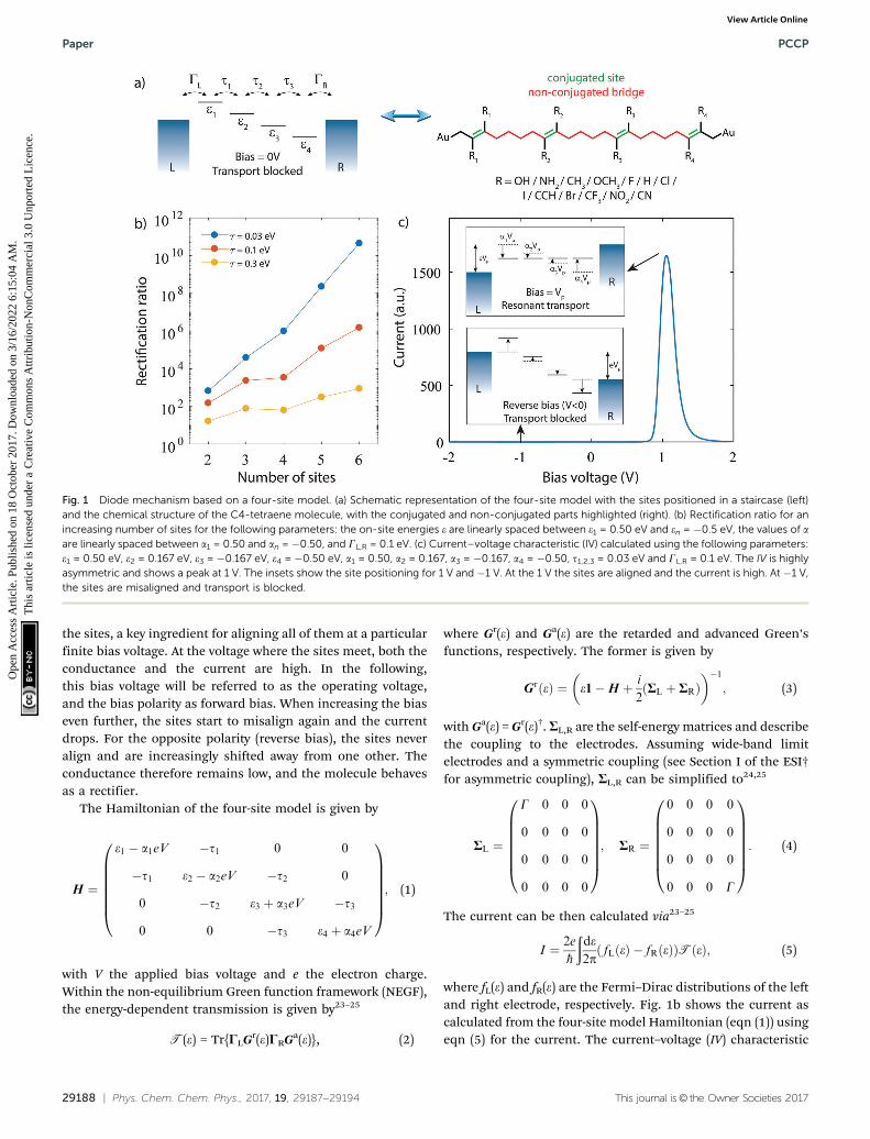
Fig. 1 depicts the concept of a rectifier based on the four-sitemodel. In Fig. 1a, the four sites are at energy ei, with i = 1, 2, 3 or4, and weakly coupled to each other in series by ti (i = 1, 2, 3).At zero bias, the four sites are positioned like a staircase(e1 4 e2 4 e3 4 e4). As the sites are not aligned, i.e., they allpossess a different energy, the transmission through such aconfiguration is low, as well as the conductance. Upon applica-tion of a bias voltage (see inset Fig. 1b), part of the voltagedrops inside the molecule, leading to a shift of the on-siteenergies by aieV (i = 1, 2, 3, 4). The rest of the voltage drop isassumed to occur at the molecule/electrode interfaces. Thisvoltage drop is crucial, as it allows for shifting the energies of
a Kavli Institute of Nanoscience, Delft University of Technology, Lorentzweg 1,
2628 CJ Delft, The Netherlands. E-mail: [email protected] Swiss Federal Laboratories for Materials Science and Technology,
Uberlandstrasse 129, 8600 Dubendorf, Switzerlandc Department of Chemical Engineering, Delft University of Technology,
Van der Maasweg 9, 2629 HZ, Delft, The Netherlands
† Electronic supplementary information (ESI) available: DFT+NEGF calculationson the H–CCH–Cl–CN substituted C4-tetraene molecule for various values of GL,R,construction of LMOs and MOs and calculations on the C4-tetraene with 2 sitesonly. The Supporting Information also provides the xyz-coordinates of theH–CCH–Cl–CN molecule, including the orbitals structure. See DOI: 10.1039/c7cp04456a
Received 3rd July 2017,Accepted 16th October 2017
DOI: 10.1039/c7cp04456a
rsc.li/pccp
PCCP
PAPER
Ope
n A
cces
s A
rtic
le. P
ublis
hed
on 1
8 O
ctob
er 2
017.
Dow
nloa
ded
on 3
/16/
2022
6:1
5:04
AM
. T
his
artic
le is
lice
nsed
und
er a
Cre
ativ
e C
omm
ons
Attr
ibut
ion-
Non
Com
mer
cial
3.0
Unp
orte
d L
icen
ce.
View Article OnlineView Journal | View Issue
29188 | Phys. Chem. Chem. Phys., 2017, 19, 29187--29194 This journal is© the Owner Societies 2017
the sites, a key ingredient for aligning all of them at a particularfinite bias voltage. At the voltage where the sites meet, both theconductance and the current are high. In the following,this bias voltage will be referred to as the operating voltage,and the bias polarity as forward bias. When increasing the biaseven further, the sites start to misalign again and the currentdrops. For the opposite polarity (reverse bias), the sites neveralign and are increasingly shifted away from one other. Theconductance therefore remains low, and the molecule behavesas a rectifier.
The Hamiltonian of the four-site model is given by
H ¼
e1 � a1eV �t1 0 0
�t1 e2 � a2eV �t2 0
0 �t2 e3 þ a3eV �t3
0 0 �t3 e4 þ a4eV
0BBBBBB@
1CCCCCCA; (1)
with V the applied bias voltage and e the electron charge.Within the non-equilibrium Green function framework (NEGF),the energy-dependent transmission is given by23–25
T(e) = Tr{CLGr(e)CRGa(e)}, (2)
where Gr(e) and Ga(e) are the retarded and advanced Green’sfunctions, respectively. The former is given by
GrðeÞ ¼ e1�H þ i
2RL þ RRð Þ
� ��1; (3)
with Ga(e) = Gr(e)†. RL,R are the self-energy matrices and describethe coupling to the electrodes. Assuming wide-band limitelectrodes and a symmetric coupling (see Section I of the ESI†for asymmetric coupling), RL,R can be simplified to24,25
RL ¼
G 0 0 0
0 0 0 0
0 0 0 0
0 0 0 0
0BBBBBB@
1CCCCCCA; RR ¼
0 0 0 0
0 0 0 0
0 0 0 0
0 0 0 G
0BBBBBB@
1CCCCCCA: (4)
The current can be then calculated via23–25
I ¼ 2e
�h
ðde2p
fLðeÞ � fRðeÞð ÞTðeÞ; (5)
where fL(e) and fR(e) are the Fermi–Dirac distributions of the leftand right electrode, respectively. Fig. 1b shows the current ascalculated from the four-site model Hamiltonian (eqn (1)) usingeqn (5) for the current. The current–voltage (IV) characteristic
Fig. 1 Diode mechanism based on a four-site model. (a) Schematic representation of the four-site model with the sites positioned in a staircase (left)and the chemical structure of the C4-tetraene molecule, with the conjugated and non-conjugated parts highlighted (right). (b) Rectification ratio for anincreasing number of sites for the following parameters: the on-site energies e are linearly spaced between e1 = 0.50 eV and en = �0.5 eV, the values of aare linearly spaced between a1 = 0.50 and an = �0.50, and GL,R = 0.1 eV. (c) Current–voltage characteristic (IV) calculated using the following parameters:e1 = 0.50 eV, e2 = 0.167 eV, e3 = �0.167 eV, e4 = �0.50 eV, a1 = 0.50, a2 = 0.167, a3 = �0.167, a4 = �0.50, t1,2,3 = 0.03 eV and GL,R = 0.1 eV. The IV is highlyasymmetric and shows a peak at 1 V. The insets show the site positioning for 1 V and �1 V. At the 1 V the sites are aligned and the current is high. At �1 V,the sites are misaligned and transport is blocked.
Paper PCCP
Ope
n A
cces
s A
rtic
le. P
ublis
hed
on 1
8 O
ctob
er 2
017.
Dow
nloa
ded
on 3
/16/
2022
6:1
5:04
AM
. T
his
artic
le is
lice
nsed
und
er a
Cre
ativ
e C
omm
ons
Attr
ibut
ion-
Non
Com
mer
cial
3.0
Unp
orte
d L
icen
ce.
View Article Online
This journal is© the Owner Societies 2017 Phys. Chem. Chem. Phys., 2017, 19, 29187--29194 | 29189
indeed shows a strong asymmetry. The current is low for allbiases, at the exception of a peak at 1 V. At this operatingvoltage, the four energies are the same, and the maximumcurrent and RR is achieved. We note that the operating voltagedepends on the model parameters ei and ai, and that with acareful choice of these parameters, i.e., a careful design of themolecule, a large range of operating voltages, RR and peakcurrents can be obtained.
A single-molecule diode, in order to behave as four sites inseries, needs to fulfill a few requirements. First of all, themolecule has to effectively behave as four-sites, meaning itshould possess four conjugated parts, which are weaklycoupled to each other. This also implies that the molecularorbitals behaving according to the four-site model should notinteract, or at least very little, with other molecular orbitals.These additional orbitals may, for instance, lead to a parasiticcurrent in the reverse bias mode, thereby deteriorating the RR.As the density of orbitals heavily depends on the total numberof electrons in the system, key for minimizing undesirableorbital contributions is to reduce the number of electrons inthe system. For this purpose, each site in the molecule shownin Fig. 1b consist of just a single ethylene unit, one of thesmallest possible conjugated units. Second, the weak inter-sitecoupling is important, as it results in a voltage drop insidethe molecule, and hence a Stark-shift of the orbitals. A weakinter-site coupling also enhances the RR as can be seen inFig. 1b, and for this reason, butylene will be used. Third, themolecular orbitals described by the four-site model arerequired to be located closely to the Fermi energy of theelectrodes, of which the alignment is strongly influenced bythe anchoring groups. Here, we use gold electrodes, with adirect carbon–gold bond (Csp3–Au) as anchoring. This anchoringpromotes transport via the highest occupied molecularorbital26–28 (HOMO). An important advantage of this anchoringgroup is also that it is chemically stable when directly bondedto the ethylene sites. This is not the case for typical anchoringgroups such as thiols, or amines. Such groups, when directlybonded to an ethylene group, are prone to isomerize to thegenerally more stable thioketones or imines, thereby destroyingboth the ethylene site and the anchoring group. Furthermore,in the calculations we assume that at zero bias (V = 0) theHOMO is on resonance with the Fermi energy. Experimentally,this may require the presence of an electrochemical29–31
or electrostatic32 gate. However, we would like to stress thatthis assumption represents the ideal case with the highestrectification. As we will show further on in this study, therectification ratio strongly depends on the level alignment;when the HOMO is several hundred meV off from the Fermienergy, rectification can decrease by several orders of magnitude.
The right panel of Fig. 1a presents the proposed molecule(with an icosa-1,7,13,19-tetraene backbone), which fulfillsthe above mentioned requirements. In the following, thismolecule will be referred to as C4-tetraene. To control theenergies of the sites, the electronegative/electronpositivechemical substituents (Ri) shown below the molecule will beemployed.
2 Theoretical methods
Electronic structures were investigated using density functionaltheory (DFT) calculations, performed using the Amsterdamdensity functional (ADF) package with the GGA PBEexchange–correlation functional and the triple-z plus polarization(TZP) basis-set.33,34 All geometries were converged to energychanges of less than 10�3 Hartree, energy gradients of less than10�3 Hartree per Å maximum and 6.7 � 10�4 Hartree per Å RMS.Transmissions were then calculated from DFT within the non-equilibrium Green’s function (NEGF) framework by coupling themolecule to wide-band electrodes18,35 (with a coupling strengthGL,R = 100 meV) involving the 6s atomic orbitals of the gold.Application of a bias voltage was performed by introducinga uniform electric field along the axis connecting the twogold atoms.
3 Results
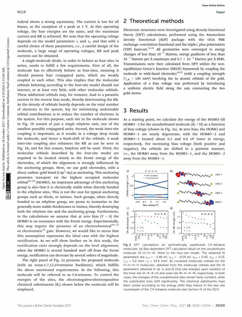
As a starting point, we calculate the energy of the HOMO tillHOMO�3 for the unsubstituted molecule (Ri = H) as a functionof bias voltage (shown in Fig. 2a). At zero bias, the HOMO andHOMO�1 are nearly degenerate, with the HOMO�2 andHOMO�3 located about 0.5 and 0.6 eV lower in energy,respectively. For increasing bias voltage (both positive andnegative), the orbitals are shifted in a pairwise manner,i.e., the HOMO away from the HOMO�1, and the HOMO�2away from the HOMO�3.
Fig. 2 DFT calculations on symmetrically substituted C4-tetraenemolecules. (a) Bias dependent DFT calculation (blue) on the unsubstitutesmolecule (H–H–H–H), fitted to the four-site model. The obtained fitparameters are e1,4 = �5.46 eV, e2,3 = �6.05 eV, a1,4 = 0.42, a2,3 = 0.13,t1,3 = 5.2 meV, t2 = 54.6 meV. (b) Localized molecular orbitals for theH–H–H–H molecules, obtained from the molecular orbitals and the fitparameters obtained in (a). (c and d) One-site energies upon variation ofthe inner site (H–R–R–H) and outer site (R–H–H–R), respectively. In bothcases, the energies of the unsubstituted sites remain fairly constant, whilethe substituted ones shift significantly. The chemical substituents havebeen sorted according to the energy shifts they induce in the two-sitecounterpart of the C4-tetraene molecule (see Section IV of the ESI†).
PCCP Paper
Ope
n A
cces
s A
rtic
le. P
ublis
hed
on 1
8 O
ctob
er 2
017.
Dow
nloa
ded
on 3
/16/
2022
6:1
5:04
AM
. T
his
artic
le is
lice
nsed
und
er a
Cre
ativ
e C
omm
ons
Attr
ibut
ion-
Non
Com
mer
cial
3.0
Unp
orte
d L
icen
ce.
View Article Online

29190 | Phys. Chem. Chem. Phys., 2017, 19, 29187--29194 This journal is© the Owner Societies 2017
To obtain the model parameters, the DFT values are numericallyfitted to the eigenvalues of the four-site Hamiltonian (eqn (1)).For symmetry reasons, the energies and shifts of the outer sitesare equal. The same holds for the energies of the inner sitesand the inter-site coupling. This reduces the number of para-meters from 11 to 6. Fitting was performed as follows. First,by combining a constraint mean-square error minimizationroutine and an unconstrained nonlinear optimization routine,the on-site energies and inter-site couplings were determined.These were then fixed, and using a second unconstrainednonlinear optimization routine, the values of a1,2 were deter-mined (for more details concerning the fitting procedure, seeSection II of the ESI†). The model parameters were then used tocalculate the four-site orbital energies, which are plotted on topof the DFT values. As can be seen in Fig. 2a, the four-site modeldescribes the DFT calculations well, both the energy separationbetween the orbitals, as well as their shift with bias.
The DFT calculations also provide the orbital shape of theHOMO orbitals. Using the fitted model parameters, one canperform a basis transformation from the molecular orbitals(MOs) to the localized molecular orbitals (LMOs), i.e., from themolecular orbitals one can obtain the electron density of thefour basis functions (sites). For a more detailed description ofthe procedure, we refer to Section III of the ESI.† The LMOs arepresented in Fig. 2b. Each LMO is localized on one of the sites,supporting the fact that charge transport in this moleculebehaves according to the four-site model.
We will now investigate how the sites can be shifted bymeans of chemical substitution. As has been demonstratedpreviously,20 chemical substitution can be used to influence theon-site energies. For this purpose, 11 substituents were chosen(see Fig. 1a), some of which are electronegative, whereas othersare electropositive. First, the inner sites were varied symmetrically,while keeping the outer sites fixed (R = H). For each group,
Fig. 3 DFT calculations on the H–CCH–Cl–CN substituted C4-tetraene molecule. (a) Bias dependent DFT calculation (blue), fitted to the four-sitemodel. The obtained fit parameters are e1 = �5.49 eV, e2 = �5.82 eV, e3 = �6.10 eV, e4 = �6.43 eV, a1 = 0.420, a2 = 0.123, a3 = 0.128, a4 = 0.415,t1 = 25.0 meV, t2 = 39.0 meV, t3 = 28.0 meV. (b) Localized molecular orbitals, obtained from the molecular orbitals and the fit parameters obtained in (a).(c) Transmission as a function of bias voltage and electron energy, obtained from NEGF calculations using GL,R = 100 meV. The shaded region denotes thebias window. Note in the bottom left corner the presence of additional lines in the transmission. These, however, are located outside the bias window andtherefore do not contribute to transport. (d) log10(I)–V characteristic calculated using DFT+NEGF. The inset shows the corresponding rectification ratio;the maximum rectification ratio exceeds 106. (e) Effect of the bias voltage on the orbital shape of the HOMO.
Paper PCCP
Ope
n A
cces
s A
rtic
le. P
ublis
hed
on 1
8 O
ctob
er 2
017.
Dow
nloa
ded
on 3
/16/
2022
6:1
5:04
AM
. T
his
artic
le is
lice
nsed
und
er a
Cre
ativ
e C
omm
ons
Attr
ibut
ion-
Non
Com
mer
cial
3.0
Unp
orte
d L
icen
ce.
View Article Online
This journal is© the Owner Societies 2017 Phys. Chem. Chem. Phys., 2017, 19, 29187--29194 | 29191
the DFT calculation and fitting procedure were performed asdescribed previously. The results are presented in Fig. 2c. Theplot shows that the energy of the unsubstituted outer sites (e1,4)remains approximately constant for all groups. The energies ofthe inner sites (e2,3), on the other hand, vary by almost 1.2 eV,between the electropositive methoxy (OCH3) and the highlyelectronegative nitro (NO2). When substituting the outer sitesinstead of the inner ones, a similar effect is observed (seeFig. 2c). The substituted sites can be varied by 1.4 eV in energy,while the unsubstituted sites remain largely unaffected. Thefact to the energy mixing between the sites is small is attributedto the weak coupling between them.
Now that we have shown that the proposed moleculebehaves according to the four-site model and that the energyof the sites can be tuned, we proceed to the realisation of asingle-molecule diode. As mentioned previously, to achievethis, the sites need to be positioned in a staircase at zero bias,and align at finite bias. Different combinations of side groupscan be used to achieve this alignment. Here, as a proof-of-concept, we first focus on the H–CCH–Cl–CN substitution,of which the coordinates and orbital structure can be foundin Section V of the ESI.† Further on, we will consider othercombinations.
The bias dependent orbital energies of this particular mole-cule are shown in Fig. 3a. At zero bias, the MOs are split inenergy, and hence are the energies of the four sites. At 1.12 V,the MOs align, and diverge again for higher bias voltages. Notethat aligning the four sites at the same energy yields four nearlydegenerate molecular orbitals, of which the energy splittingdepends on the inter-site couplings t1,2,3. Like in Fig. 3a, themodel parameters can be obtained by fitting the MO energies,and are used to validate the four-site model, and to computethe corresponding LMOs. As the fit now requires 11 parameters,a different approach is needed to extract them from the calcula-tions (see Section II of the ESI† or more information). Ourstarting point is to create two symmetric molecules, one fromthe left side of the molecule (H–CCH–CCH–H), and one from theright side (CN–Cl–Cl–CN). These symmetric molecules are fittedas described previously. The fitted parameters are then used asinitial guesses for a series of unconstrained nonlinear optimiza-tion routines. We note that the fitted parameters resulting fromthese routines do differ from the initial guess. A prediction ofthe diode properties based on the two symmetric molecules istherefore not straightforward. Importantly, the plot in Fig. 3ashows that the fit reproduces the DFT values well. The LMOsconstructed from the fit parameters are depicted in Fig. 3b. Here,again, each LMO is localized on one of the ethylene sites, inaccordance with the four-site model.
Using the NEGF formalism, the transmission of the H–CCH–Cl–CN molecule is calculated. Fig. 3c presents a colormapof the logarithm of the transmission as a function of both thebias voltage and the electron energy. Here, the transmissionis low everywhere, except at the point at which the fourorbitals meet (1.12 V). An important observation is that noother orbital significantly contributes to transport in thisbias and energy range, which was one of our design criteria.
From the bias-dependent transmission, the current can becalculated. Assuming the HOMO to be on resonance with theFermi energy at V = 0, the IV curve shown in Fig. 3d is obtained.This curve is highly asymmetric, with a large current peak at1.12 V. At the opposite bias polarity, the current remains ordersof magnitude lower. The inset shows the rectification ratio(|I(V)/I(�V)|), which reaches as high as 1.3 � 106 at 1.12 V. Thislarge dependence of the current on the bias voltage can also beunderstood by considering the shape of the MOs upon applica-tion of an electric field. Fig. 3e presents the evolution of thewave function of the HOMO with bias voltage. The plot showsthat only at a bias voltage of 1.12 V the orbital is fullydelocalized across the entire molecule and hence allows forefficient charge transport. For other voltages, the HOMO ishighly localized and poorly conducting. A similar trend isobserved for the other relevant occupied molecular orbitals,as shown in Section VI of the ESI.†
By varying the chemical substituents, the energies of thefour sites can be tuned to meet at a specified bias voltage.In Fig. 3 we used the substituents H–CCH–Cl–CN. In principle,many combinations of substituents are possible (114), eventough most of these are not expected to yield a favorablealignment, and hence no large rectification ratio. Due tocomputational limitations, however, we do not calculate theproperties of all these molecules. Instead, we make an educatedguess based on the electronegativity/electronpositivity of thegroups obtained in Fig. 2. In order to obtain a staircase of theon-site energies, the first site should either be electronpositiveor only slightly electronegative (OCH3, CH3, H, Br, I, F, CCH,Cl). The second and third site should be slightly to moderatelyelectronegative (H, Br, I, F, CCH, Cl), while the fourth siteshould be very electronegative (CN, NO2, CF3). This choicegreatly reduces the number of combinations. For each of theremaining 864 molecules the electronic structure and transmis-sion were calculated as described previously using DFT+NEGFincluding all orbitals. From the calculated current the rectificationratio, operating voltage and peak current were extracted basedon the maximum current in the IV characteristic. Note that no fitparameters are required to obtain these results.
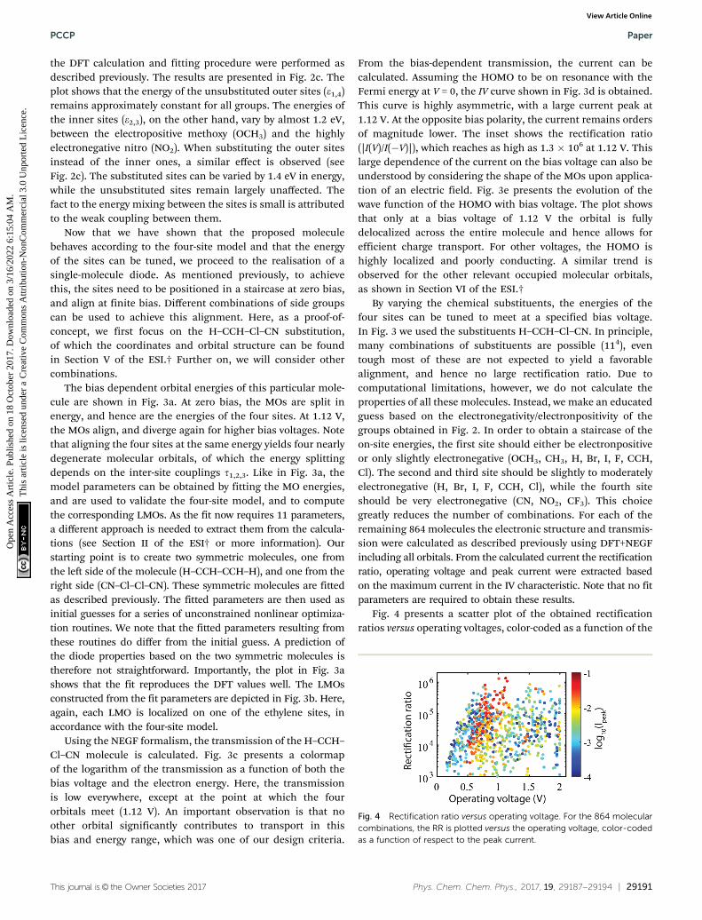
Fig. 4 presents a scatter plot of the obtained rectificationratios versus operating voltages, color-coded as a function of the
Fig. 4 Rectification ratio versus operating voltage. For the 864 molecularcombinations, the RR is plotted versus the operating voltage, color-codedas a function of respect to the peak current.
PCCP Paper
Ope
n A
cces
s A
rtic
le. P
ublis
hed
on 1
8 O
ctob
er 2
017.
Dow
nloa
ded
on 3
/16/
2022
6:1
5:04
AM
. T
his
artic
le is
lice
nsed
und
er a
Cre
ativ
e C
omm
ons
Attr
ibut
ion-
Non
Com
mer
cial
3.0
Unp
orte
d L
icen
ce.
View Article Online
29192 | Phys. Chem. Chem. Phys., 2017, 19, 29187--29194 This journal is© the Owner Societies 2017
peak current. On first sight, a large range of rectification ratiosand operating voltages is accessible. However, for many ofthese combinations, the peak current is low. Interestingly, thehigh current combinations (red dots) form a cloud whichextends from 0.5 V to 1.0 V for ratios varying between 104 till106. This cloud is attributed to combinations of side groups ofwhich the sites are well aligned. For more details about thespecific side-group combinations, see we refer to Section VII ofthe ESI.† Within this rectification range, the diode propertiescan be tuned as desired, albeit with a tendency of having higherrectification at higher operating voltages. This tendency canbe attributed to the fact that for higher operating voltages thecurrent in reverse bias mode is suppressed more significantlythan for lower operating voltages.
4 Discussion
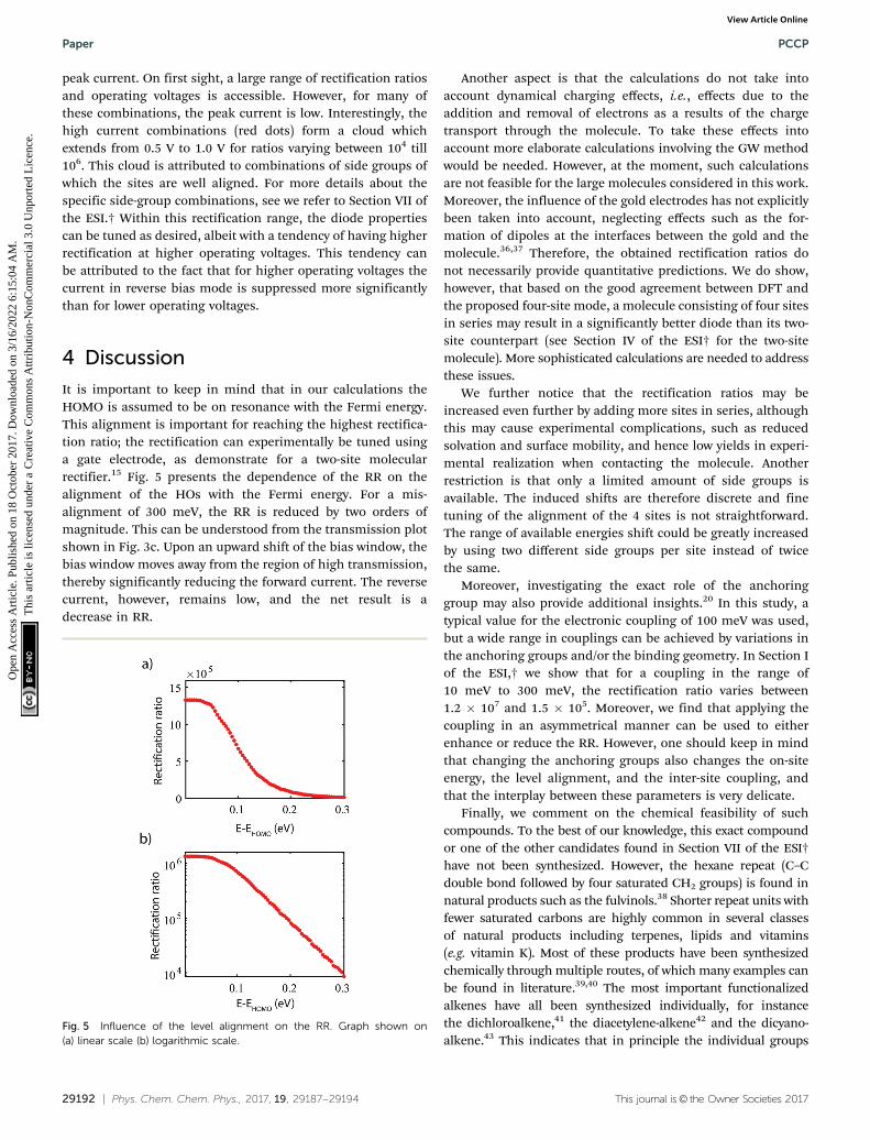
It is important to keep in mind that in our calculations theHOMO is assumed to be on resonance with the Fermi energy.This alignment is important for reaching the highest rectifica-tion ratio; the rectification can experimentally be tuned usinga gate electrode, as demonstrate for a two-site molecularrectifier.15 Fig. 5 presents the dependence of the RR on thealignment of the HOs with the Fermi energy. For a mis-alignment of 300 meV, the RR is reduced by two orders ofmagnitude. This can be understood from the transmission plotshown in Fig. 3c. Upon an upward shift of the bias window, thebias window moves away from the region of high transmission,thereby significantly reducing the forward current. The reversecurrent, however, remains low, and the net result is adecrease in RR.
Another aspect is that the calculations do not take intoaccount dynamical charging effects, i.e., effects due to theaddition and removal of electrons as a results of the chargetransport through the molecule. To take these effects intoaccount more elaborate calculations involving the GW methodwould be needed. However, at the moment, such calculationsare not feasible for the large molecules considered in this work.Moreover, the influence of the gold electrodes has not explicitlybeen taken into account, neglecting effects such as the for-mation of dipoles at the interfaces between the gold and themolecule.36,37 Therefore, the obtained rectification ratios donot necessarily provide quantitative predictions. We do show,however, that based on the good agreement between DFT andthe proposed four-site mode, a molecule consisting of four sitesin series may result in a significantly better diode than its two-site counterpart (see Section IV of the ESI† for the two-sitemolecule). More sophisticated calculations are needed to addressthese issues.
We further notice that the rectification ratios may beincreased even further by adding more sites in series, althoughthis may cause experimental complications, such as reducedsolvation and surface mobility, and hence low yields in experi-mental realization when contacting the molecule. Anotherrestriction is that only a limited amount of side groups isavailable. The induced shifts are therefore discrete and finetuning of the alignment of the 4 sites is not straightforward.The range of available energies shift could be greatly increasedby using two different side groups per site instead of twicethe same.
Moreover, investigating the exact role of the anchoringgroup may also provide additional insights.20 In this study, atypical value for the electronic coupling of 100 meV was used,but a wide range in couplings can be achieved by variations inthe anchoring groups and/or the binding geometry. In Section Iof the ESI,† we show that for a coupling in the range of10 meV to 300 meV, the rectification ratio varies between1.2 � 107 and 1.5 � 105. Moreover, we find that applying thecoupling in an asymmetrical manner can be used to eitherenhance or reduce the RR. However, one should keep in mindthat changing the anchoring groups also changes the on-siteenergy, the level alignment, and the inter-site coupling, andthat the interplay between these parameters is very delicate.
Finally, we comment on the chemical feasibility of suchcompounds. To the best of our knowledge, this exact compoundor one of the other candidates found in Section VII of the ESI†have not been synthesized. However, the hexane repeat (C–Cdouble bond followed by four saturated CH2 groups) is found innatural products such as the fulvinols.38 Shorter repeat units withfewer saturated carbons are highly common in several classesof natural products including terpenes, lipids and vitamins(e.g. vitamin K). Most of these products have been synthesizedchemically through multiple routes, of which many examples canbe found in literature.39,40 The most important functionalizedalkenes have all been synthesized individually, for instancethe dichloroalkene,41 the diacetylene-alkene42 and the dicyano-alkene.43 This indicates that in principle the individual groups
Fig. 5 Influence of the level alignment on the RR. Graph shown on(a) linear scale (b) logarithmic scale.
Paper PCCP
Ope
n A
cces
s A
rtic
le. P
ublis
hed
on 1
8 O
ctob
er 2
017.
Dow
nloa
ded
on 3
/16/
2022
6:1
5:04
AM
. T
his
artic
le is
lice
nsed
und
er a
Cre
ativ
e C
omm
ons
Attr
ibut
ion-
Non
Com
mer
cial
3.0
Unp
orte
d L
icen
ce.
View Article Online
This journal is© the Owner Societies 2017 Phys. Chem. Chem. Phys., 2017, 19, 29187--29194 | 29193
are chemically stable and that all parts of the molecule can besynthesized. Investigating whether the exact molecule, or one ofthe other candidates found in Section VII of the ESI† can besynthesized requires extensive additional synthetic effort, and isbeyond the scope of the current study.
5 Conclusions
In conclusion, we provide guide-lines for the design of highlyefficient single-molecule rectifiers based on an intuitive four-site model, involving four weakly coupled molecular sites inseries. The model gives rise to a single-molecule resonanttunneling diode by aligning the energies of the four sites at aparticular bias voltage. Using DFT+NEGF calculations, weexplore how chemical substitution of the molecule can be usedto control the energy of these sites. With proper choice of thesubstituents a favorable alignment of the sites can be achieved,leading to highly efficient diodes, with rectification ratiosexceeding a million.
Conflicts of interest
There are no conflicts to declare.
Acknowledgements
The authors would like to thank Dr Jos Thijssen for supportwith the DFT calculations and Dr Michel Calame for carefulreading of the manuscript. This research was carried out withfinancial support from the Dutch Foundation for FundamentalResearch on Matter (FOM), the Dutch Organisation for Scien-tific Research (NWO), the Ministry of Education, Culture andScience (OCW), ERC Grant no. 240299, and by an ERC advancedgrant (Mols@Mols).
References
1 M. Souto, L. Yuan, D. C. Morales, L. Jiang, I. Ratera, C. A.Nijhuis and J. Veciana, J. Am. Chem. Soc., 2017, 139,4262–4265.
2 L. Qiu, Y. Zhang, T. L. Krijger, X. Qiu, P. van’t Hof,J. C. Hummelen and R. C. Chiechi, Chem. Sci., 2017, 8,2365–2372.
3 J. A. Smerdon, N. C. Giebink, N. P. Guisinger, P. T. Darancetand J. R. Guest, Nano Lett., 2016, 16, 2603–2607.
4 N. Nerngchamnong, L. Yuan, D.-C. Qi, J. Li, D. Thompsonand C. A. Nijhuis, Nat. Nanotechnol., 2013, 8, 113–118.
5 L. Yuan, N. Nerngchamnong, L. Cao, H. Hamoudi, E. delBarco, M. Roemer, R. K. Sriramula, D. Thompson andC. A. Nijhuis, Nat. Commun., 2015, 6, 6324.
6 J. Trasobares, D. Vuillaume, D. Theron and N. Clement,Nat. Commun., 2016, 7, 12850.
7 X. Chen, M. Roemer, L. Yuan, W. Du, D. Thompson,E. del Barco and C. A. Nijhuis, Nat. Nanotechnol., 2017, 12,797–803.
8 M. Elbing, R. Ochs, M. Koentopp, M. Fischer, C. vonHanisch, F. Weigend, F. Evers, H. B. Weber and M. Mayor,Proc. Natl. Acad. Sci. U. S. A., 2005, 102, 8815–8820.
9 I. Diez-Perez, J. Hihath, Y. Lee, L. Yu, L. Adamska, M. A.Kozhushner, I. I. Oleynik and N. Tao, Nat. Chem., 2009, 1,635–641.
10 J. Hihath, C. Bruot, H. Nakamura, Y. Asai, I. Diez-Perez,Y. Lee, L. Yu and N. Tao, ACS Nano, 2011, 5, 8331–8339.
11 E. Lortscher, B. Gotsmann, Y. Lee, L. Yu, C. Rettner andH. Riel, ACS Nano, 2012, 6, 4931–4939.
12 A. Batra, P. Darancet, Q. Chen, J. S. Meisner, J. R. Widawsky,J. B. Neaton, C. Nuckolls and L. Venkataraman, Nano Lett.,2013, 13, 6233–6237.
13 T. Kim, Z. F. Liu, C. Lee, J. Neaton and L. Venkataraman,Proc. Natl. Acad. Sci. U. S. A., 2014, 111, 10928–10932.
14 S. Sherif, G. Rubio-Bollinger, E. Pinilla-Cienfuegos,E. Coronado, J. C. Cuevas and N. Agraıt, Nanotechnology,2015, 26, 291001.
15 M. L. Perrin, E. Galan, R. Eelkema, J. M. Thijssen, F. Grozemaand H. S. van der Zant, Nanoscale, 2016, 8, 8919–8923.
16 C. Guo, K. Wang, E. Zerah-Harush, J. Hamill, B. Wang,Y. Dubi and B. Xu, Nat. Chem., 2016, 8, 484–490.
17 A. Aviram and M. A. Ratner, Chem. Phys. Lett., 1974, 29, 277–283.18 M. L. Perrin, R. Frisenda, M. Koole, J. S. Seldenthuis,
J. A. Celis Gil, H. Valkenier, J. C. Hummelen, N. Renaud,F. C. Grozema, J. M. Thijssen, D. Dulic and H. S. J. van derZant, Nat. Nanotechnol., 2014, 9, 830–834.
19 K. Stokbro, J. Taylor and M. Brandbyge, J. Am. Chem. Soc.,2003, 125, 3674–3675.
20 M. L. Perrin, E. Galan, R. Eelkema, F. C. Grozema, J. M.Thijssen and H. S. J. van der Zant, J. Phys. Chem. C, 2015,119, 5697–5702.
21 C. Van Dyck and M. A. Ratner, Nano Lett., 2015, 15, 1577–1584.22 M. Kilgour and D. Segal, J. Phys. Chem. C, 2017, 119,
25291–25297.23 Y. Meir and N. S. Wingreen, Phys. Rev. Lett., 1992, 68, 2512–2515.24 A.-P. Jauho, N. S. Wingreen and Y. Meir, Phys. Rev. B:
Condens. Matter Mater. Phys., 1994, 50, 5528–5544.25 H. Haug and A.-P. Jauho, Quantum Kinetics in Transport and
Optics of Semiconductors, Springer, Berlin, Heidelberg, 1997.26 Z.-L. Cheng, R. Skouta, H. Vazquez, J. R. Widawsky,
S. Schneebeli, W. Chen, M. S. Hybertsen, R. Breslow andL. Venkataraman, Nat. Nanotechnol., 2011, 6, 353–357.
27 J. R. Widawsky, W. Chen, H. Vazquez, T. Kim, R. Breslow,M. S. Hybertsen and L. Venkataraman, Nano Lett., 2013, 8,2889–2894.
28 A. Etcheverry-Berrıos, I. Olavarrıa, M. L. Perrin, R. Dıaz-Torres, D. Jullian, I. Ponce, J. H. Zagal, J. Pavez, S. O.Vasquez, H. S. J. van der Zant, D. Dulic, N. Aliaga-Alcaldeand M. Soler, Chem. – Eur. J., 2016, 22, 12808–12818.
29 I. Dıez-Perez, Z. Li, S. Guo, C. Madden, H. Huang, Y. Che,X. Yang, L. Zang and N. Tao, ACS Nano, 2012, 6, 7044–7052.
30 M. Baghernejad, D. Z. Manrique, C. Li, T. Pope, U. Zhumaev,I. Pobelov, P. Moreno-Garcıa, V. Kaliginedi, C. Huang,W. Hong, C. Lambert and T. Wandlowski, Chem. Commun.,2014, 50, 15975–15978.
PCCP Paper
Ope
n A
cces
s A
rtic
le. P
ublis
hed
on 1
8 O
ctob
er 2
017.
Dow
nloa
ded
on 3
/16/
2022
6:1
5:04
AM
. T
his
artic
le is
lice
nsed
und
er a
Cre
ativ
e C
omm
ons
Attr
ibut
ion-
Non
Com
mer
cial
3.0
Unp
orte
d L
icen
ce.
View Article Online
29194 | Phys. Chem. Chem. Phys., 2017, 19, 29187--29194 This journal is© the Owner Societies 2017
31 B. Capozzi, Q. Chen, P. Darancet, M. Kotiuga, M. Buzzeo,J. B. Neaton, C. Nuckolls and L. Venkataraman, Nano Lett.,2014, 14, 1400–1404.
32 M. L. Perrin, E. Burzurı and H. S. J. van der Zant, Chem. Soc.Rev., 2015, 44, 902–919.
33 G. te Velde, F. M. Bickelhaupt, S. J. A. van Gisbergen,C. Fonseca Guerra, E. J. Baerends, J. G. Snijders andT. Ziegler, J. Comput. Chem., 2001, 22, 931–967.
34 C. Fonseca Guerra, J. G. Snijders, G. te Velde and E. J.Baerends, Theor. Chem. Acc., 1998, 99, 391–403.
35 C. J. O. Verzijl, J. S. Seldenthuis and J. M. Thijssen, J. Chem.Phys., 2013, 138, 094102.
36 G. Heimel, E. Zojer, L. Romaner, J.-L. Bredas and F. Stellacci,Nano Lett., 2009, 9, 2559–2564.
37 C. Van Dyck and M. A. Ratner, J. Phys. Chem. C, 2017, 121,3013–3024.
38 M. L. Ciavatta, G. Nuzzo, K. Takada, V. Mathieu, R. Kiss,G. Villani and M. Gavagnin, J. Nat. Prod., 2014, 77, 1678–1684.
39 A. M. Daines, R. J. Payne, M. E. Humphries and A. D. Abell,Curr. Org. Chem., 2003, 7, 1–15.
40 T. J. Maimone and P. S. Baran, Nat. Chem. Biol., 2007, 3,396–407.
41 T. Schlama, K. Gabriel, V. Gouverneur and C. Mioskowski,Angew. Chem., Int. Ed., 1997, 36, 2342–2344.
42 J.-F. Nierengarten, D. Guillon, B. Heinrich and J.-F. Nicoud,Chem. Commun., 1997, 1233–1234.
43 S. Arai, T. Sato and A. Nishida, Adv. Synth. Catal., 2009, 351,897–1904.
Paper PCCP
Ope
n A
cces
s A
rtic
le. P
ublis
hed
on 1
8 O
ctob
er 2
017.
Dow
nloa
ded
on 3
/16/
2022
6:1
5:04
AM
. T
his
artic
le is
lice
nsed
und
er a
Cre
ativ
e C
omm
ons
Attr
ibut
ion-
Non
Com
mer
cial
3.0
Unp
orte
d L
icen
ce.
View Article Online