Embed Size (px)
Citation preview

DESIGN OF ALL-BOLTED EXTENDED DOUBLE ANGLE, SINGLE ANGLE, AND
TEE SHEAR CONNECTIONS
By
PERRY GREEN, Ph.D. THOMAS SPUTO, Ph.D., P.E.
ADAM HIGGINS
DEPARTMENT OF CIVIL & COASTAL ENGINEERING UNIVERSITY OF FLORIDA GAINESVILLE, FLORIDA
A REPORT PRESENTED TO THE AMERICAN INSTITUTE OF STEEL CONSTRUCTION
JANUARY 2005

ii

iii
TABLE OF CONTENTS page LIST OF TABLES............................................................................................................. vi
LIST OF FIGURES .......................................................................................................... vii
ABSTRACT....................................................................................................................... ix
INTRODUCTION ...............................................................................................................1
1.1 Background.............................................................................................................1 1.2 Objective and Scope of Work.................................................................................2
LITERATURE REVIEW ....................................................................................................3
2.1 Connection Types ...................................................................................................3 2.2 Bolted Connections.................................................................................................4 2.3 Moment-Rotation Behavior of Shear Connections.................................................6 2.4 Coping of Beams ....................................................................................................9 2.5 Tee Connection Behavior .....................................................................................10 2.6 Conclusion ............................................................................................................11
OPTIMUM BAY STUDY.................................................................................................12
3.1 Bay Studies Program ............................................................................................12 3.2 Bay Study Parameters...........................................................................................12
3.2.1 Bay Geometry.............................................................................................12 3.2.2 Steel Deck and Slab Properties...................................................................12 3.2.3 Loading.......................................................................................................13 3.2.4 Vibration Criteria and Deflections .............................................................13 3.2.5 Shear Studs and Composite Action ............................................................14 3.2.6 Member Selection and Camber ..................................................................14
3.3 Optimum Bay Study Results ................................................................................15 LIMIT STATES.................................................................................................................20
4.1 Extended Double Angle Connection ....................................................................20 4.2 Extended Single Angle Connection......................................................................21 4.3 Extended Tee Connection.....................................................................................22 4.4 Limit State Calculations .......................................................................................23
4.4.1 Shear Yielding ............................................................................................23 4.4.2 Shear Rupture .............................................................................................23 4.4.3 Flexural Yielding........................................................................................24

iv
4.4.4 Flexural Rupture.........................................................................................26 4.4.5 Block Shear Rupture...................................................................................27 4.4.6 Bolt Bearing................................................................................................28 4.4.7 Bolt Slip......................................................................................................30 4.4.8 Bolt Shear ...................................................................................................31
EXTENDED DESIGN TABLE CONSTRUCTION.........................................................32
5.1 Extended Single and Double Angle Table Construction......................................32 5.2 Extended Tee Table Construction ........................................................................33
5.2.1 Extended Tee Tables ..................................................................................34 5.2.2 Extended Tee Equation...............................................................................35
DESIGN EXAMPLES.......................................................................................................40
6.1 Extended Double Angle Design Example ............................................................40 6.2 Extended Single Angle Design Example..............................................................43 6.3 Extended Tee Design Example.............................................................................47
FINITE ELEMENT ANALYSIS ......................................................................................51
7.1 Introduction...........................................................................................................51 7.2 Finite Element Model Development.....................................................................52
7.2.1 FE Discretization for Angle........................................................................52 7.2.2 FE Discretization for Girder .......................................................................53 7.2.3 FE Discretization for Bolts .........................................................................54
7.3 FE Model Contact Conditions ..............................................................................55 7.4 FE Model Initial Conditions .................................................................................60 7.5 FE Model Applied Loading ..................................................................................60 7.6 FE Model Boundary Conditions...........................................................................61 7.7 FE Model Material Behavior ................................................................................62 7.8 FE Analysis Results ..............................................................................................63
SUMMARY AND CONCLUSIONS ................................................................................80
LIST OF REFERENCES...................................................................................................82
3/4-INCH DIAMETER ALL-BOLTED A36 STEEL DOUBLE ANGLE CONNECTIONS ........................................................................................................85
7/8-INCH DIAMETER ALL-BOLTED A36 STEEL DOUBLE ANGLE CONNECTIONS ......................................................................................................110
1-INCH DIAMETER ALL-BOLTED A36 STEEL DOUBLE ANGLE CONNECTIONS ......................................................................................................135
3/4-INCH DIAMETER ALL-BOLTED A992 STEEL DOUBLE ANGLE CONNECTIONS ......................................................................................................160
7/8-INCH DIAMETER ALL-BOLTED A992 STEEL DOUBLE ANGLE CONNECTIONS ......................................................................................................185

v
1-INCH DIAMETER ALL-BOLTED A992 STEEL DOUBLE ANGLE CONNECTIONS ......................................................................................................210
3/4-INCH DIAMETER ALL-BOLTED A36 STEEL SINGLE ANGLE CONNECTIONS ......................................................................................................235
7/8-INCH DIAMETER ALL-BOLTED A36 STEEL SINGLE ANGLE CONNECTIONS ......................................................................................................260
1-INCH DIAMETER ALL-BOLTED A36 STEEL SINGLE ANGLE CONNECTIONS ......................................................................................................285
3/4-INCH DIAMETER ALL-BOLTED A992 STEEL SINGLE ANGLE CONNECTIONS ......................................................................................................310
7/8-INCH DIAMETER ALL-BOLTED A992 STEEL SINGLE ANGLE CONNECTIONS ......................................................................................................335
1-INCH DIAMETER ALL-BOLTED A992 STEEL SINGLE ANGLE CONNECTIONS ......................................................................................................360
3/4-INCH DIAMETER ALL-BOLTED A992 STEEL TEE CONNECTIONS .............385
7/8-INCH DIAMETER ALL-BOLTED A992 STEEL TEE CONNECTIONS .............397
1-INCH DIAMETER ALL-BOLTED A992 STEEL TEE CONNECTIONS ................409

vi
LIST OF TABLES
Table page 3.1 Range of Girders and Beams for Typical Bay Framing Dimensions.......................17
7.1 Finite Element Model Contact Group Descriptions .................................................56
7.2 Finite Element Model Contact Surface, Pair, and Group Interactions.....................57
7.3 FE Model Steel Material Properties .........................................................................63
7.4 FE Model Material Groups ......................................................................................63
7.5 Corner Node Numbering..........................................................................................64

vii
LIST OF FIGURES
Figure page 2.1 Rotational Rigidity of Steel Connections...................................................................3
2.2 Deformation of Web Angle Connection ....................................................................6
2.3 Mechanism of the Part of the Angle Connected to the Column Flange at the Ultimate Condition.....................................................................................................7
2.4 Beam Cope ...............................................................................................................10
3.1 Bay Studies Results for 20-Foot by 20-Foot Bay with a 10-Foot Beam Spacing....15
3.2 Bay Studies Beam Calculation Sheet for 20-Foot by 20-Foot Bay with a 10-Foot Beam Spacing...........................................................................................................16
4.1 Pin and Point of Fixity .............................................................................................20
4.2 Moment Eccentricity ................................................................................................25
4.3 Block Shear Rupture Failure Planes.........................................................................27
5.1 Eccentricity Coefficients for Tees............................................................................36
5.2 Retained Eccentricity Curves ...................................................................................37
5.3 Coefficient C1 Curve ................................................................................................38
5.4 Coefficient C2 Curve ................................................................................................39
6.1 Plan View of Extended Double Angle Connection Location...................................40
6.2 Extended Double Angle Detail.................................................................................42
6.3 Standard Double Angle Detail .................................................................................43
6.4 Plan View of Extended Single Angle Connection Location ....................................44
6.5 Extended Single Angle Detail ..................................................................................46
6.6 Standard Single Angle Detail ...................................................................................47

viii
6.7 Plan View of Extended Tee Connection Location ...................................................48
6.8 Extended Tee Detail .................................................................................................50
6.9 Standard Tee Connection .........................................................................................50
7.1 FE Model Element Meshing ....................................................................................68
7.2 FE Model Applied Loading......................................................................................69
7.3 FE Model Boundary Conditions ..............................................................................70
7.4 Bi-linear Stress-Strain Curve for A36 Steel Material ..............................................71
7.5 Bi-linear Stress-Strain Curve for A572 Gr. 50 Steel Material .................................71
7.6 Bi-linear Stress-Strain Curve for A325 Bolt Material..............................................72
7.7 Bi-linear Stress-Strain Curve for A490 Bolt Material..............................................72
7.8 Applied Load vs. Horizontal Z- and Vertical Y- Tip Displacement of FE Model with 5 in. Protruded Angle Leg and Material Group I .............................................73
7.9 Comparison of Applied Load vs. End Rotation Curves for FE Models with 3.5 and 5 in. Protruded Legs and Material Group I........................................................73
7.10 Comparison of Applied Load vs. End Rotation Curves for FE Models with A325 and A490 Bolts and 5 in. Protruded Leg ........................................................74
7.11 Comparison of Applied Load vs. End Rotation Curves for FE Models with A36 and A572 Gr. 50 Angles and 5 in. Protruded Leg....................................................74
7.12 Effective Stress Plots of the Single Angle, Bolts and Girder Web for the FE Model with 3.5 in. Protruded Leg and Material Group I, Time Step = 1.000....75
7.13 Effective Stress Plots of the Single Angle, Bolts and Girder Web for the FE Model with 3.5 in. Protruded Leg and Material Group I, Time Step = 193.2 (Maximum Applied Load) .......................................................................................76
7.14 Effective Stress Plots of the Single Angle, Bolts and Girder Web for the FE Model with 3.5 in. Protruded Leg and Material Group II, Time Step = 193.8 9 (Maximum Applied Load) ...............................................................77
7.15 Effective Stress Plots of the Single Angle, Bolts and Girder Web for the FE Model with 3.5 in. Protruded Leg and Material Group III, Time Step = 239.62 (Maximum Applied Load) ................................................................78

ix
ABSTRACT
DESIGN OF ALL-BOLTED EXTENDED DOUBLE ANGLE, SINGLE ANGLE, AND TEE SHEAR CONNECTIONS
This report presents a methodology for the design of all-bolted extended double angle, single angle, and tee shear connections. The report covers only the design of extended connections that involve beams and girders, but the principles set forth can be applied to connections to columns as well. Current steel connection design methodologies do not have standards for the design of extended connections which do not require that the beam be coped to allow clearance for the girder flange. Coping is an expensive and time consuming process which fabricators like to avoid if at all possible. Extended connections are a practical way to avoid coping. Using basic mechanics and code specific equations, a practical design for all-bolted extended shear connections can be derived. The derived methodology is used to formulate design tables that simplify the process. This report includes examples of how to use the design tables to design all-bolted extended connections. The tables include design resistances for a wide range of angle and tee materials and bolts diameters, as well as different connection types.

1
CHAPTER 1 INTRODUCTION
1.1 Background
Many fabricators and erectors prefer the use of high strength bolts over welding
which requires more time to make the connection and higher skilled labor. Therefore,
many steel fabricators favor using all-bolted connections in order to eliminate the need
for shop and/or field welding.
Steel connections are categorized as either fully restrained (FR) or partially
restrained (PR). FR connections assume the connections have sufficient stiffness to
maintain the angles between intersecting members (American Institute of Steel
Construction (AISC) 1999). PR connections assume the connections have insufficient
stiffness to maintain the angles between intersecting members (AISC 1999). When
connection restraint is ignored, commonly designated as simple framing, the connections
have the following requirements:
1. The connections and the connected members shall be adequate to resist the factored gravity loads as “simple beams.”
2. The connections and connected members shall be adequate to resist the factored lateral loads.
3. The connections shall have sufficient inelastic rotation capacity to avoid overload of fasteners or welds under combined factored gravity and lateral loads.
The scope of this research project covers only shear connections and their behavior.
In the case of typical beam-to-girder shear connections, the beam must be coped
(top coped, bottom coped, or top and bottom coped) in order to provide clearance for the

2
2
girder flange/s. Coping requires the flange of the beam be removed to allow for the
necessary clearance. Coping not only requires consideration of other limit states, such as
lateral-torsional buckling or local buckling at the reduced section, but coping incurs extra
cost as well. All-bolted extended shear connections are a possible solution to eliminate
coping.
1.2 Objective and Scope of Work
The purpose of this research project is to determine whether all-bolted extended
shear connections, specifically single angle, double angle, and tee connections, are
feasible. Currently there are no specific provisions in the AISC Manual of Steel
Construction (2001) for extended connections of any type. The purpose is to analytically
simulate the response of all-bolted connections under a range of loading conditions so
that the general behavior of the connection can be established. An analytical
methodology will be developed using the current 3rd Edition AISC-LRFD Specification
and first principles of engineering mechanics (AISC 1999). The results of this procedure
will be used to determine applicable limit states and to develop a rational design
procedure for all-bolted extended single angle, double angle, and tee connections.
The scope of this project includes a review of past research done in the area of
bolted connections and the development of new analytical models based on existing
models developed by previous researchers as well as original models developed at the
University of Florida. The models will be used to develop design criteria for the new
connections, and design strength tables will be developed using the new design criteria.

3
CHAPTER 2 LITERATURE REVIEW
A great deal of research has been performed regarding the design and behavior of
steel connections the past 50 years, the results of which have been used to create Chapter
J of the AISC Manual of Steel Construction that deals with joints.
2.1 Connection Types
There are several “standard” types of structural steel connections. They are
generally classified into three behavior categories: rigid, semi-rigid, and simple. The
difference among the three can be shown through a plot of end moment versus end
rotation.
Figure 2.1 Rotational Rigidity of Steel Connections (Astaneh 1989)
The M-� curve OABC in Figure 2.1 represents the general behavior of connections.
Segment OA of the M-� curve is the segment where connections behave as fully-
restrained connection. Connections in this range have an initial rotational restraint

4
4
greater than or equal to LEI18
where E is the material’s elastic modulus, I is the moment
of inertia of the cross-section of the beam and, L is the length of the beam. Connections
with an initial rotational restraint less than or equal to LEI2
represented by Segment ABC
are considered simply and do not develop any significant moment. The two initial
rotational stiffness curves represent the boundaries for a partial-restrained connection. As
the figure shows, no connection is truly fixed or truly pinned, but these assumptions
greatly simplify the design process. This research project deals only with simple
connections which assume that there will be no end moment developed in the beam and
that the beam supports will allow unrestrained rotations.
2.2 Bolted Connections
There are two common joining methods in current steel construction: welds and
bolts. This research project only deals with bolted connections; therefore, the
background information pertains mostly to bolted connections. Bolted connections
became popular during the 1950’s because previous research had shown that bolts could
be used to replace rivets in connections (Kulak et al. 1987). Until that time only rivets
were used in connections.
Bolted connections can be tightened to specific levels. The first is a snug tight
connection. The bolt is tightened using an ordinary spud wrench to bring the piles, which
in this case are the angles or tees and the web of the beam, into firm contact (RCSC
2000). Alternately, a bolt can be pretensioned, in which case it is a pretensioned joint. A
bolt must be tightened to its minimum pretension force listed in Table J3.1 of the AISC
Specification (AISC 1999). There is no difference in the strength of the two types of

5
5
joints, but pretensioning is usually necessary when the connection is subjected to cyclic
or tension loads (Kulak et al. 1987). Slip critical connections are required to meet the
provisions of Chapter J3.8 of the AISC Specification (AISC 1999). This connection is
designed in order to prevent any slip between the faying surfaces. Early research showed
that high-strength bolts can be used in a connection in the same manner as rivets (Kulak
et al. 1987). This discovery led to the common use of high-strength bolts in connections.
Today bolted connections are very popular because they are relatively inexpensive
compared to field welding, and they are easy to install.
Bolted shear connections are used in modern steel construction, and extensive
research has been conducted on these types of connections (Chen and Lui 1988). There
are various types of common shear connections: double angle, single angle, tee, single
plate, etc.
The connections that are related to this project include double angle, single angle
and tees. Double angle connections are made with two angles, one on each side of the
beam to be supported (AISC 1999). These angles may be bolted or welded to the
supported beam as well as to the supporting member. Single angle connections are made
using an angle on one side of the web of the beam to be supported. This angle is
preferably shop bolted or welded to the supporting member and field bolted to the
supported beam (AISC 1999). Tee connections are made using a structural tee. The tee
is preferably shop bolted or welded to the supporting member and field bolted to the
supported beam (AISC 1999).
Research has shown that almost all rotation is provided in the detail material,
usually either angles or plates (Kennedy 1969). A typical deformed shape can be seen in

6
6
Figure 2.2. As Figure 2.2 shows, most of the rotation in the connection occurs in the legs
of the angle that are in the plane of the supporting member. This is relevant because the
behavior of extended connections should be similar. The gage distance for the “in-plane”
legs for extended and normal shear connections is the same.
Figure 2.2 Deformation of Web Angle Connection (Kulak et al. 1987)
2.3 Moment-Rotation Behavior of Shear Connections
One possible moment-rotation relationship for bolted double and single angle shear
connections was quantified by Kishi and Chen (1990) using a power model relationship
between moment in the connection and end rotation. The general deformation of the
connection was based on the following assumptions:
1. The center of rotation of the connection was near the mid-depth of the beam during the first few increments of loading.
2. The deformation and subsequent tearing of the connection angles resulted primarily from bending moment, and the effect of shear deformation on the connection behavior was relatively small.
The yield mechanisms depicted in Figure 2.3 were also used in determining the
moment-rotation relationship:

7
7
Figure 2.3 Mechanism of the Part of the Angle Connected to the Column Flange at the Ultimate Condition (Kishi and Chen 1990)
The final form of the moment-rotation relationship is given by Equation 2.1 (Kishi
and Chen 1990).

n1
n
0
r
rki
1
RM
���
����
����
���
ΘΘ+
Θ=
(Eq. 2.1)
Where:
M = moment in connection (kip-in)
Rki = initial connection stiffness (kip-in)
rΘ = a rotation of connection (radians)
0Θ = a reference plastic rotation (radians)
n = shape factor
The initial connection stiffness is given by Equation 2.2 (Kishi and Chen 1990).
( ) ( ) ( )αβ−αβαβαβα=
sinhcosh)cosh(
3Gt
R3
ki
(Eq. 2.2)
Where:
G = shear modulus of the steel (ksi)
t = thickness of angle leg (in)
α = 4.2967
β = p
1l
g
Where:
g1 = gage distance (in)
lp = length of angle (in)
The reference plastic rotation is given by Equation 2.3 (Kishi and Chen 1990).
ki
u0 R
M=Θ
(Eq. 2.3)
Where:
Mu = ultimate moment capacity of connection
The model was verified by comparison to various experimental results (Kishi and
Chen 1990). The model agrees with Astaneh’s recommendations for simple connections,
where a simple connection is one that develops a moment at the beam end less than or
equal to 20% of the fixed end moment (Astaneh 1989). Most experiments, such as the
ones Kishi and Chen used to verify their power model, have been performed for beam-to-
column connections only, and have not been directly performed for beam-to girder
connections.
2.4 Coping of Beams
Beam-to-girder shear connections are quite common in steel structures, but they
can be quite complicated to design. Most beam-to-girder shear connections require that
the beam be coped as shown in Figure 2.4 in order to allow clearance for the girder flange
and to maintain the floor elevation.
A beam cope requires time and incurs cost to make, and it also reduces the strength
of the section that must be accounted for by the designer. This coped section possesses a
reduced bending and torsional stiffness, so that buckling, both local and lateral, need be
considered (Cheng 1993). High stress concentrations at the coped corner can also induce
localized yielding that might cause the beam to fail in inelastic local buckling (Yam et al.
2003).

10
10
Figure 2.4 Beam Cope
The AISC-LRFD Specification (Appendix F1) requires that coped beams be
checked for flexural yielding and local web buckling at the coped section (AISC 1999).
This is computationally time consuming because it requires that the coped section
properties be calculated. For wide flange sections, this calculation process has been
simplified in the AISC Manual (2001) through design aids which have been created that
provide these reduced coped section properties.
Today, it is also standard practice to grind the coped area smooth after the flame
cutting process in order to avoid the likelihood of fatigue cracks developing if the beam is
placed under cyclic loading.
2.5 Tee Connection Behavior
Much research conducted on shear connections focuses on angles, but there has
been research conducted on the behavior of tees (Astaneh and Nader 1990). Inelastic
analyses of the beams indicate that the end rotation of a simply supported beam
approaches 0.03 radians when the mid-span bending moment reaches 99% of the plastic
moment (Astaneh 1989). Tee connections allow this behavior as long as the tee meets
the following criterion:

11
11
3. The bolt diameter to the tab (stem) thickness ratio must be greater than or equal to two ( )2t
d ≥ . This criterion guarantees that the tab (stem) experiences ductile
bearing failure before the bolts fracture in shear (Thornton 1996).
2.6 Conclusion
The previous research mentioned here has been used to determine a design
methodology for all-bolted extended double angle, single angle, and tee connections.
The Kishi and Chen model shows that the plastic hinge is developed in the in-plane or
girder connected angle legs. This assumption is used in the development of the design
tables. The load passes through the centerline of the girder. The plastic hinge is assumed
to develop at the centerline of the girder which requires that the outstanding leg bolts be
designed for an eccentric load. Prying action can be ignored because the plastic hinge is
developed at the girder web.
The extended connection does not require the beam to be coped, so the limit states
due to coping do not need to be checked. This reduces the amount of work needed to
develop the design tables.
12
CHAPTER 3 OPTIMUM BAY STUDY
3.1 Bay Studies Program
The Excel spreadsheet Bay Studies 4.1 (AISC 2003) is used to determine a
practical range of beam and girder sizes, as well as connection loadings (factored end
reactions). The spreadsheet provides a range of beam and girder sizes for user defined
parameters such as girder and beam length, loading, composite action, etc. The
spreadsheet also provides a materials cost per beam, so that a price estimate can be
constructed.
3.2 Bay Study Parameters
3.2.1 Bay Geometry
A range of bays from 20 foot x 20 foot to 40 foot x 40 foot is considered practical,
and is used in this study. The bay dimensions are varied in 5-foot increments with no
more than 10 feet between the girder length and beam length in any particular bay and
vice versa. In order to have a comprehensive number of section sizes, the number of
filler beams varies from one per bay to four per bay. The total number of bay geometries
considered is 40.
3.2.2 Steel Deck and Slab Properties
The steel deck properties are constant for the whole study, so that the dead load
weight added by the steel deck and concrete will not be a factor in the study. The 2-inch
deep steel deck is given an average rib width of 6 inches, and a rib spacing of 12 inches.
These values are consistent with typical steel deck used in low to mid-rise steel frame

13
building construction. The concrete for the slab is 3000 psi concrete with a specific
weight of 145 pounds per cubic foot (pcf). The concrete slab extends 3 inches above the
steel deck, for a total slab depth of 5 inches. The construction is considered to be
unshored, which is a common practice.
3.2.3 Loading
The loading for the bays is broken down into four components: dead load, live
load, superimposed dead load, and construction live load. The dead load is the combined
weight of the steel deck and concrete slab, which is calculated by the spreadsheet to be
51.8 pounds per square foot (psf). The live load is 125 psf which covers a broad range of
loading conditions. The superimposed dead load is 20 psf which is the default value for
the spreadsheet. The construction live load is also 20 psf which is the default value. The
spreadsheet allows for live load reduction, but live load reduction is not considered in the
study.
3.2.4 Vibration Criteria and Deflections
The program allows for vibration to be considered in the design process or for a
vibrations check to be made. The program allows the user to change the percentage of
superimposed dead and live load that participates in damping. Also, the damping ratio
for the floor system may be set by the user as well. No vibration check or design is used
for the study.
The deflections allowed for the beam and girders may also be set by the user. The
limits may be input as either absolute deflections or in limiting deflection ratios, such as
L/240. The spreadsheet checks the deflection from live load, dead load, and
superimposed dead load. The spreadsheet also checks deflections from combined loading

14
effects. The allowable deflection ratios are kept at the default values of L/240 for the
dead load, and L/360 for the superimposed dead and live loads.
3.2.5 Shear Studs and Composite Action
The spreadsheet allows the user to define the range of composite action allowable
(if any) for the member. The spreadsheet allows a minimum and maximum percentage of
composite action in the member. The minimum for the study is 25% composite action,
and the maximum is 75% composite action. The studs are 3/4-inch in diameter and 4
inches in height and cost $2.50 per stud. This is considered typical for a 5-inch deep slab.
The spacing of the shear studs are within the design criteria given in Chapter I of the
AISC Specification, which is the default value (AISC 1999). The spreadsheet also lets
the users define the spacing limits if they so desire. In this study, the default values are
used.
3.2.6 Member Selection and Camber
The spreadsheet allows the user to define the range of wide flange shapes that may
be selected. The default values are W12 to W33 shapes for beams, and W18 to W33
shapes for girders. The study uses the default values for both the beams and the girders.
The spreadsheet also allows the user to set the amount of camber (if any) that may
be used in the beams and girders. The user can set the minimum and maximum amount
of camber to be used, and the camber increment. The default value for the minimum
camber is 0.75 inches, and the maximum value is 2 inches. The default camber
increment is 0.25 inches. The spreadsheet requires that the amount of dead load to be
cambered be set. The default is 75% of the dead load. The default cost of cambering is
$20.00 per beam for 2 inches of camber. The study uses all the default values for
cambering.

15
3.3 Optimum Bay Study Results
The results from the spreadsheet are given in a table format. An example is given
in Figure 3.1:
Figure 3.1 Bay Studies 4.1 (2003) Results for 20-Foot by 20-Foot Bay with a 10-Foot
Beam Spacing
The spreadsheet also provides the calculation worksheet for the beams and girders
as shown in Figure 3.2.
The reactions, beam sizes, and girder sizes are recorded and the data is reduced for
the 40 cases. Table 3.1 shows the reduced data from the optimum bay study. The range

16
of girders is W18x35 to W33x130 with most being W24’s or smaller. The range of
beams is W12x14 to W27x84 with most being W21’s or smaller. Additionally, the
factored end reaction is provided.
Figure 3.2 Bay Studies 4.1 (2003) Beam Calculation Sheet for 20-Foot by 20-Foot Bay
with a 10-Foot Beam Spacing

17
Table 3.1 Range of Girders and Beams for Typical Bay Framing Dimensions Range of Girders and Beams for Typical Bay Framing Dimensions
Bay Size 20-feet x 20-feet
Girder Beam Length (ft) Section Length (ft) Section
Beam Spacing (ft)
Factored End Shear
(kips) 20 W18x35 20 W12x19 10 29 20 W18x35 20 W12x14 6.67 19 20 W18x35 20 W12x14 5 14
Bay Size 20-feet x 30-feet Girder Beam
Length (ft) Section Length (ft) Section Beam
Spacing (ft) Factored
End Shear (kips)
20 W18x40 30 W18x35 10 44 20 W18x35 30 W14x22 6.67 29
Bay Size 25-feet x 20-feet Girder Beam
Length (ft) Section Length (ft) Section Beam
Spacing (ft) Factored
End Shear (kips)
25 W21x44 20 W14x22 12.5 35 25 W21x44 20 W12x16 8.33 24 25 W18x40 20 W12x14 6.33 18 25 W18x35 20 W12x14 5 14
Bay Size 25-feet x 25-feet Girder Beam
Length (ft) Section Length (ft) Section Beam
Spacing (ft) Factored
End Shear (kips)
25 W21x44 25 W16x31 12.5 45 25 W21x44 25 W16x26 8.33 30 25 W21x44 25 W12x17 6.33 23 25 W21x44 25 W12x12 5 18
Bay Size 25-feet x 35-feet Girder Beam
Length (ft) Section Length (ft) Section Beam
Spacing (ft) Factored
End Shear (kips)
25 W24x62 35 W24x55 12.5 64 25 W24x55 35 W18x35 8.33 42
Bay Size 30-feet x 20-feet Girder Beam
Length (ft) Section Length (ft) Section Beam
Spacing (ft) Factored
End Shear (kips)
30 W24x55 20 W16x26 15 43 30 W21x44 20 W12x19 10 29

18
Table 3.1-Continued Range of Girders and Beams for Typical Bay Framing Dimensions (cont.)
Bay Size 30-feet x 25-feet
Girder Beam Length (ft) Section Length (ft) Section
Beam Spacing (ft)
Factored End Shear
(kips) 30 W24x55 25 W18x35 15 54 30 W24x55 25 W16x26 10 36 30 W24x55 25 W14x22 7.5 27 30 W24x55 25 W12x14 6 22
Bay Size 30-feet x 30-feet Girder Beam
Length (ft) Section Length (ft) Section Beam
Spacing (ft) Factored
End Shear (kips)
30 W24x76 30 W21x44 15 65 30 W24x76 30 W18x35 10 44 30 W24x67 30 W16x31 7.5 33
Bay Size 30-feet x 35-feet Girder Beam
Length (ft) Section Length (ft) Section Beam
Spacing (ft) Factored
End Shear (kips)
30 W27x84 35 W24x55 15 76 30 W27x84 35 W21x44 10 51 30 W24x76 35 W16x31 7.5 38
Bay Size 30-feet x 40-feet Girder Beam
Length (ft) Section Length (ft) Section Beam
Spacing (ft) Factored
End Shear (kips)
30 W30x90 40 W24x82 15 87 30 W30x90 40 W21x50 10 58 30 W27x84 40 W18x40 7.5 44
Bay Size 35-feet x 35-feet Girder Beam
Length (ft) Section Length (ft) Section Beam
Spacing (ft) Factored
End Shear (kips)
35 W30x99 35 W24x55 17.5 84 35 W30x99 35 W21x50 11.67 59 35 W30x90 35 W18x35 8.8 45
Bay Size 35-feet x 40-feet Girder Beam
Length (ft) Section Length (ft) Section Beam
Spacing (ft) Factored
End Shear (kips)
35 W33x118 40 W24x68 17.5 102

19
Table 3.1-Continued Range of Girders and Beams for Typical Bay Framing Dimensions (cont.)
Bay Size 35-feet x 40-feet
Girder Beam Length (ft) Section Length (ft) Section
Beam Spacing (ft)
Factored End Shear
(kips) 35 W33x118 40 W24x55 11.67 68 35 W30x99 40 W21x44 8.8 51
Bay Size 40-feet x 40-feet Girder Beam
Length (ft) Section Length (ft) Section Beam
Spacing (ft) Factored
End Shear (kips)
40 W33x130 40 W27x84 20 116 40 W33x130 40 W24x55 13.33 78 40 W33x130 40 W21x50 10 58 40 W33x118 40 W21x44 8 47
The range of factored end reactions range from 14 kips for a 20-foot x 20-foot bay
with a 5-foot beam spacing to 116 kips for a 40-foot x 40-foot bay with a 20-foot beam
spacing. The average factored end shear is 47 kips.
The wide flange sections in Table 3.1 are chosen because they are the least cost but
not necessarily least weight. The cost of the bay includes the cost of the steel, the cost of
the shear stud installation, and the cost of cambering. All of the defaults for cost are used
and are described earlier in this chapter.
The information from Table 3.1 can be used to reduce the number of all-bolted
extended angle and tee tables given in the appendices of this document, by removing the
tables that can not be used for the wide flange sections given in Table 3.1.

20
CHAPTER 4 LIMIT STATES
4.1 Extended Double Angle Connection
Double angles or two-sided connections have certain advantages over one sided
connections. Double angle connections can resist larger end reactions because the
supported member bolts are in double shear and the eccentricity perpendicular to the
beam axis need not be considered for workable gages. The pin in an extended and
standard double angle connection is located at the girder web as shown in Figure 4.1.
Figure 4.1 Pin and Point of Fixity

21
Double angle connections usually require that the supported member be coped in
order to make the connection. A connection to a coped beam has three limit states at the
cope that do not occur in a connection to an uncoped beam; lateral-torsional buckling,
local web buckling, and fatigue cracking (Cheng 1993). These limit states are not
considered in the analysis of extended double angle connections because there is no
coping involved. The following limit states are considered in the design of an extended
double angle connection:
1. Shear Yielding 2. Shear Rupture 3. Flexural Yielding 4. Flexural Rupture 5. Block Shear Rupture 6. Bolt Bearing 7. Bolt Slip 8. Bolt Shear
The bolt limit states include effects from the eccentricity of the loading. These
limit states are discussed in more detail in Section 4.4 of this chapter.
4.2 Extended Single Angle Connection
A single angle connection uses one angle to make the connection. Single angle
connections have the following advantages:
4. Shop attachment of the connection elements to the support, simplifying shop fabrication and erection
5. Reduced material and shop labor requirements
6. Ample erection clearance is provided
7. Excellent safety during erection since double connections often can be eliminated (AISC 1999)
Single angles also have several disadvantages:
8. The supporting member bolts must be designed as eccentrically loaded

22
9. Single angles have less capacity because the outstanding leg bolts are in single shear and only one angle is used in the connection.
As with the double angle connection the supported beam must typically be coped in order
to construct the connection. An extended single angle connection does not require coping
of the supported beam; therefore, limit states for coping the beam are no longer
applicable. An extended single angle connection includes all of the limit states that were
stated previously for extended double angle connections. The point of fixity for a single
angle connection is the same as a double angle connection. Single angle connections also
require that the bolts perpendicular to the beam are designed for shear and moment due to
the eccentricity on these bolts. Therefore, both the supporting and supported bolt lines
must be designed with eccentricity considered.
4.3 Extended Tee Connection
Extended tee connections are very similar to extended single angle connections in
that the supported member bolts are in single shear. Therefore, these two types of
connections have less capacity than an extended double angle connection.
As in the previous types of connections, the line of force in a tee connection acts
through the centerline of the supporting member which is the pin of the connection as
shown in Figure 4.1. Therefore, prying action is not considered in the design of any of
the extended connections. Also, tee connections have two lines of bolts on the supporting
member that are symmetrical, so eccentricity on these bolts is not a consideration. Tees
are available with a wide range of stem lengths making them the most versatile extended
connection type.

23
4.4 Limit State Calculations
4.4.1 Shear Yielding
Shear yielding is a ductile limit state that is a function of the gross shear area of the
element (Green et al. 2001). For single angles and tees, the shear area is equal to the
following equation:
aav thA = (Eq. 4.1)
ha = the length of the angle or tee
ta = the thickness of the outstanding angle leg or stem thickness
Double angles have twice the shear area of a single angle by virtue of having two legs in
shear. The shear area is used to calculate the shear yielding capacity of the connection.
This equation is shown below:
yvn FA6.0R φ=φ (Eq. 4.2)
Fy = yield stress of the detail material
φ = 0.90
The equation given above is Equation J5-3 from the AISC-LRFD Specification
(AISC 1999). The φ term is a resistance factor that is dependent on the limit state. For
yielding limit states, φ is 0.90. The yield stress, Fy, is either 36 ksi or 50 ksi for A36 or
A992 steels, respectively (AISC 2001). Angles used in the study are designed using both
A36 and A992 steel while tees are designed with only A992 steel. This limit state is
calculated for a range of angles and tees from 5.50 inches to 35.50 inches in length.
4.4.2 Shear Rupture
Shear rupture is also a limit state for the connection. The failure plane is located
along the line of the bolts in the supported angle leg/s or tee stem; therefore, a reduced or

24
net area is used for calculating the shear rupture strength of the connection. The net shear
area is calculated using the following equation:
ahanv t)161
d(nhA ��
�
� += − (Eq. 4.3)
n = the number of bolts
dh = the bolt hole diameter
For the calculation of Anv the AISC-LRFD Specification requires that 16
1 of an inch be
added to the nominal bolt hole diameter when calculating net areas (AISC 1999). The net
shear area is the sum of both angles for double angle connections. The shear rupture
capacity is given by the equation below:
unvn FA6.0R φ=φ (Eq. 4.4)
Fu = the ultimate stress of the detail material
φ = 0.75
This equation is also Equation J4-1 in the AISC-LRFD Specification. For rupture limit
states, φ is 0.75. The ultimate stress, Fu, is either 58 ksi or 65 ksi for A36 and A992
steels, respectively (AISC 2001). The range of angle and tee lengths is the same as for
shear yielding.
4.4.3 Flexural Yielding
Flexural yielding of the outstanding angle leg or tee stem is checked in determining
the design capacity of the extended connections. In standard connections, flexural
yielding need not be considered because the eccentricity of the load is within specified
gage distances (AISC 2001). For most flexural limit states, the plastic section modulus,
Z, is used to determine the flexural design strength. The AISC-LRFD Manual (2001)

25
allows the designer to use the elastic section modulus, S, as a conservative approximation
when calculating the flexural limit states in connections. The elastic section modulus for
the angles and tees is calculated using Equation 4.5:
6ht
S2
aa= (Eq. 4.5)
The flexural design strength is given by Equation 4.6:
yn SFM φ=φ (Eq. 4.6)
φ = 0.90
In order to compare the flexural limit states to the others the moment is converted
to a load that acts at an eccentricity. The eccentricity, e, varies depending upon the
supported leg or stem length. The eccentricity is assumed to be the distance from the
centerline of the supported bolts to the face of the supported web as shown in Figure 4.2.
Figure 4.2 Moment Eccentricity
The figure shows the dimension that is used to determine the eccentricity.
Therefore, the flexural capacity of the connection is dependent upon the eccentricity

26
unlike for shear limit states. As the eccentricity increases; the flexural strength decreases.
The connection capacity, φRn, is therefore:
eM
Rn
nφ=φ
(Eq. 4.7)
e = eccentricity
4.4.4 Flexural Rupture
Flexural rupture is an ultimate strength limit state. The net elastic section modulus
is conservatively used to determine the section capacity. In Section 15 of the AISC-
LRFD Manual, an equation is provided for the net section modulus for bracket plates
(AISC 2001). The AISC Manual permits this equation to be used to determine the net
elastic section modulus for shear connections. This is a conservative approach because
the equation is for the net elastic section modulus, Snet, not the net plastic modulus. The
equation for Snet is given as Equation 4.8:
( )
����
�
�
���
���
� +−−=
a
h22
2a
anet
h161
d1nnsh
6t
S
(Eq. 4.8)
s = bolt spacing
The equation is found at the bottom of Table 15-2 in the AISC-LRFD Manual. The
equation to determine the flexural rupture is below:
unetn FSM φ=φ (Eq.4.9)
φ = 0.75
The flexural rupture strength of a connection is given in terms of a moment, so the
moment, Mn, must be divided by the load eccentricity shown in Figure 4.2 to calculate

27
the end reaction. As with flexural yielding, flexural rupture follows the same trend that is
that as the eccentricity increases, the capacity decreases. Therefore the connection
capacity is equal to Equation 4.7.
4.4.5 Block Shear Rupture
Block shear rupture is a limit state in which the failure path includes both an area
subject to shear and an area subject to tension (Green et al. 2001). In standard
connections there are two possible elements that can experience block shear rupture; the
connection element (angle or tee) and the net coped section. Extended connections do
not require the supported member to be coped, so block shear rupture will not occur. The
only element that needs to be checked for block shear rupture is the angle or the tee.
Block shear rupture also has the possibility of occurring across more than one failure
plane, but there is only one possible failure plane for an extended connection. Figure 4.2
shows both the shear and tension failure planes.
Figure 4.3 Block Shear Rupture Failure Planes

28
There are two equations that are used to determine the block shear rupture strength
of a connection. The equation that controls is dependant on values of tension rupture and
shear rupture, and which of the two is greater. All the connections in this research project
are controlled by shear rupture, so Equation J4-3b in the AISC-LRFD Specification is
used to determine the block shear rupture strength (1999). The equation is shown below:
[ ] [ ]ntunvugtynvun AFAF6.0AFAF6.0R +φ≤+φ=φ (Eq. 4.10)
Anv = net area subject to shear
Agt = gross area subject to tension
Ant = net area subject to tension
φ = 0.75
Block shear rupture can be conservatively approximated as the shear rupture strength of
the connection. The gross area in tension, Agt, is very small, and the difference between
the block shear, Anv, and the net area for shear rupture is the value of Lc, which is the
clear distance from the outlying bolt and the connection angle or tee edge.
4.4.6 Bolt Bearing
Bolt bearing is concerned with the deformation of material at the loaded edge of the
bolt holes (Green et al. 2001). Bearing capacity of the connection is influenced by the
proximity of the bolt to the loaded edge, as well as, the spacing between the bolts.
The bolt edge distance is assumed to be 1-1/4 inches. This edge distance is the
same as the one given in the double angle tables of Part 10 in the AISC Manual. This
edge distance is the minimum for connections using 3/4-inch diameter through 1-inch
diameter bolts. This makes the connection as small as possible which widens its range of
applicability. Extended connections do not have the same carrying capacity as

29
equivalent-number-of-bolt standard connections. Therefore, an extra bolt is required in
an extended connection to make up for this loss in strength, which requires more space.
Lengthening the edge distance would add more capacity to an extended connection, but
not enough to overcome the requirement for an additional bolt.
Bolt bearing for the beam and girder are not explicitly checked in the extended
connection tables. These two limit states must be checked separately in order to verify
the design strength of the connection. For both the girder and the beam the bolt hole
deformation will be the limiting factor because there is no chance of the bolt tearing out.
Part 10 of the AISC Manual has numbers for these limit states given in a kips per inch of
web thickness format.
All bolt limit states are treated as eccentrically loaded. Eccentricity produces both
a rotation and a translation of one connection element with respect to the other. The
combined effect of this rotation and translation is equivalent to a rotation about a point
defined as the instantaneous center of rotation (IC). In order to determine the bolt bearing
capacity the instantaneous center (IC) method is utilized. This method includes the
nonlinearity of the bolt deformation. The AISC-LRFD Manual has tables with IC
method coefficients in Chapter 7 (2001). These tables are designed for a bolt group
containing 2 to 12 bolts and eccentricities up to 36 inches. These coefficients are
multiplied by the bearing capacity of a single bolt.
The bolt bearing equation given in the AISC-LRFD Specification as Equation J3-2a
is given below:
uahuacn Ftd4.2FtL2.1R φ≤φ=φ (Eq. 4.11)
φ = 0.75

30
Lc = clear distance, in the direction of the force, between the edge of the hole and
the edge of the adjacent hole or edge of the material.
The Equation 4.11 considers bolt hole deformation at service loads, a conservative
assumption. The equation above does not include effects from load eccentricity. The
value from the equation above for one bolt is determined and multiplied by the
appropriate C coefficient for the IC method. The equation is Equation 4.12:
nn CrR φ=φ (Eq. 4.12)
φ = 0.75
C = IC coefficient
rn = the bearing design strength for one bolt
4.4.7 Bolt Slip
Bolt slip is considered in slip critical connections. In the design tables in the
appendices of this document, slip critical connections for three different hole types are
considered. Equations for bolt slip do not include effects of bolt eccentricity. The slip
critical value for one bolt is determined and multiplied by the C coefficient from the IC
method. The equation for bolt slip is given below:
bsbn NNT13.1R µφ=φ (Eq. 4.13)
φ = resistance factor ranging from 1.0 to 0.85
µ = mean slip coefficient (Class A µ = 0.33, Class B µ = 0.5)
Tb = minimum fastener tension given in AISC LRFD Specification Table J3.1
Ns = number of slip planes
Nb = number of bolts

31
The φ -factor for standard holes is 1.0, while the φ -factor for oversized and short-slotted
holes is 0.85. The minimum fastener tension is a function of bolt diameter. The slip
capacity of the connection is the slip capacity of one bolt multiplied by the C coefficient.
4.4.8 Bolt Shear
Bolt shear is applicable to each bolted ply of a connection that is subjected to shear
(Green et al. 2001). The shear strength of a bolt is directly proportional to the number of
interfaces (shear planes) between the plies within the grip of the bolt that a single shear
force is transmitted through. The outstanding legs of double angle connections have two
shear planes, while the outstanding leg or stem for single angle and tee connections have
one shear plane. The equation for bolt shear is shown below:
bsbvn NNAFR φ=φ (Eq. 4.14)
φ = 0.75
Fv = bolt ultimate shear stress
Ab = nominal cross-sectional area of bolt
Ns = number of shear planes
Nb = number of bolts
As with the other bolt limit states, the bolt shear equation does not include the effects of
load eccentricity. The shear strength of one bolt is calculated and multiplied by the C
coefficient. This is equivalent to Equation 4.12 except the φ -factor is not applied
because it is applied in Equation 4.14.

32
CHAPTER 5 EXTENDED DESIGN TABLE CONSTRUCTION
5.1 Extended Single and Double Angle Table Construction
The process that has been used to develop the design tables for single and double
angles is divided into three phases:
10. Determine the applicable limit states for these connections;
11. Calculate the connection strength based on the limit states previously determined; and,
12. Reduce the data and compile into a series of connection design aid tables.
The first and second phases have been discussed in Chapter 3.
Tables have been developed for six, seven, eight, and nine-inch leg angles; 3/4, 7/8
and, 1-inch diameter ASTM A325/F1852 and ASTM A490 bolts, and ASTM A36 and
ASTM A992 angle material. Currently, 9-inch angles are not available from steel mills,
but are included because of the possible future demand for longer angle legs if the use of
extended connections is shown to be cost effective. All supporting and supported
members are assumed to be A992 wide flange structural shapes. All edge distances are
assumed to be 1¼-inch. The controlling limit state is highlighted in the extended angle
connection tables. All the design tables are located in the Appendix section of this
document. The single and double angle tables are categorized by angle material (either
A36 or A992) and bolt diameter (3/4-inch, 7/8-inch, 1-inch).
All connections that appear in the tables have controlling limit states that involve
the bolts or the material around the bolts in the case of bolt bearing. The connection

33
angles never reach their yield or fracture limit states before a bolt limit state is reached.
For many of the longer outstanding leg connections, the minimum connection strength
(10 kips) specified in Section J1.7 of the AISC-LRFD Specification (AISC 1999) is not
reached before the connection fails. Also, not all wide flange structural shapes allow for
extended angle connections when used as girders. Many heavier wide flange sections
have flanges whose flange width, bf, will not allow for any practical extended connection
to be used. In the tables, all design strength values are provided even though any
connection with a strength less than 10 kips cannot be used.
The third phase of constructing the tables consists of compiling all of the
strengths from each limit state and determining the controlling limit state. All of these
calculations were computed via an Excel Spreadsheet. The tables are categorized by the
following criteria:
• Length of outstanding angle leg • Number of bolts in a single row • Bolt type (A325/F1852, A490) • Connection type (Threads excluded (X), included (N), or slip critical (SC)) • Angle thickness • Bolt diameter • Type of bolt hole (STD, OVS, SSLT)
The tables display the overall design strength of the connections, φ Rn and the
appropriate limit state. Bolt bearing on the beam and girder webs is not considered in the
extended angle design strength tables, and must be checked separately by the designer.
5.2 Extended Tee Table Construction
The extended tee tables are developed using the same methodology as the single
and double angle tables with some exceptions. Tees and angles are similar in that they
both have the same limit states, and that the controlling limit states always involve the

34
bolts or the material around the bolts in the case of bolt bearing. The load is assumed to
have a line of action through the girder web which would eccentrically load the outlying
or stem bolts. The supporting member bolts are in a state of direct shear. The tee stem
must also be checked for flexural yielding and flexural rupture.
Extended tees pose the challenge of determining what eccentricity to use because
there are such a wide variety of tee sections. Two approaches are used to calculate the
design capacity of an extended tee connection:
1. Specify a rational number of eccentricities that cover most cases of extended tee connections, i.e. eccentricities that will extend beyond a majority of girder flanges;
2. Formulate an equation that is a function of eccentricity and the number of bolts. The equation gives the appropriate eccentricity coefficient that is used to determine the strength of the connection.
5.2.1 Extended Tee Tables
The extended tee design tables are given in Appendices M through O of this
document. The tee tables have a similar format to the angle tables, with some
differences. Due to the wide range of tees available, any eccentricity is possible. Using
the data from the parametric bay study, a practical range of eccentricities was determined.
The range of eccentricities for the tables ranges from 5 inches to 12 inches. This range
covers numerous beam-to-girder connections found in commercial steel building design.
The designer may also linearly interpolate between the values of eccentricity.
The wide variety of tees also allows for a wide range of stem thicknesses. The
stem thickness is one of the limiting factors in the design of extended tee connections.
The controlling limit state changes depending on the stem thickness. After a certain
limiting thickness is reached, the limit state changes from a bearing limit state to either a
bolt shear or slip critical limit state. The limiting thickness is equal to the shear or slip

35
capacity divided by the bearing capacity for a one inch thick tee stem. Therefore, the
values given in the tables are in units of either kips per inch of tee stem thickness or in
kips, depending on the controlling limit state. The highlighted rows are in units of kips
and have either bolt shear or bolt slip as the controlling limit state depending on the
connection type. The unhighlighted rows are in units of kips per inch of tee stem
thickness for the bolt bearing limit state.
The AISC Specification requires that tees are configured so that flexing of the tee
accommodates the simple-beam end rotation (AISC 1999). The AISC Manual gives an
equation in Part 9 for maximum tee stem thickness.
.in161
2d
t bmaxs +=
(Eq. 5.1)
db = bolt diameter (in.)
The tables for extended tees do not check this requirement for ductility. There is the
possibility that because of the extended stem length that this requirement is not
applicable.
5.2.2 Extended Tee Equation
In order to have a more general solution than the one presented by the extended tee
tables, Equation 5.1 has been formulated to determine the design capacity of an extended
tee connection. The limit states for an extended tee connection always involve the bolts
connecting the tee to the supported member. Therefore, a similar approach to the C-
coefficients given in Chapter 7 in the AISC Manual (2001) has been developed.
The formulation involved plotting the IC coefficients for each bolt group (from 2
bolts to 12 bolts). The plots for each group were than curve-fit to determine a general
relationship.

36
0
2
4
6
8
10
12
0 4 8 12 16 20 24 28 32 36
Eccentricity (in)
Ecc
entr
icity
Coe
ffic
ient
2-Bolts
3-Bolts
4-Bolts
5-Bolts
6-Bolts
7-Bolts
8-Bolts
9-Bolts
10-Bolts
11-Bolts
12-Bolts
Figure 5.1 Eccentricity Coefficients for Tees
The curves are logarithmic in nature, but a governing equation could not be
determined using all twelve curves. Using the parametric bay study to determine the
highest practical shear reaction, the number of curves was reduced from 11 to 7. The
excluded curves include those using 9 bolts or above, therefore; the retained curves
include only those using between 2 and 8 bolts. The retained curves were bounded
between an eccentricity of 5 and 16 inches because this was deemed the practical range
for extended connections.
The reduced set of curves was fit with logarithmic curves and from that a general
equation was derived:
( ) 2x1 CelnCIC += (Eq. 5.2)
Where:
IC = instant center coefficient

37
C1 = first coefficient of number of bolts
C2 = second coefficient of number of bolts
ex = bolt eccentricity
The coefficients were determined by curve fitting the reduced results shown in Figure
5.1. Those results are given in Figure 5.2 shows the new plot with the fitted curves.
y = -2.6102Ln(x) + 9.2081
y = -2.1251Ln(x) + 7.3217
y = -1.6339Ln(x) + 5.4909
y = -1.1179Ln(x) + 3.7177
y = -0.659Ln(x) + 2.1403
y = -0.3228Ln(x) + 1.0498
y = -3.0385Ln(x) + 11.036
0
1
2
3
4
5
6
7
4 6 8 10 12 14 16 18 20
Eccentricity (in.)
Coe
ffic
ient
Series1
Series2
Series3
Series4
Series5
Series6
Series7
Log.(Series6)
Log.(Series5)
Log.(Series4)
Log.(Series3)
Log.(Series2)
Log.(Series1)
Log.(Series7)
n=8
n=7
n=6
n=5
n=4n=3
n=2
Figure 5.2 Retained Eccentricity Curves
The coefficients for the fitted curves from Figure 5.2 are plotted with respect to
number of bolts. Figures 5.3 and 5.4 show the coefficient curves with the fit equations
for coefficients C1 and C2. Equations 5.2 and 5.3 give the final expression for
coeffiecents C1 and C2, respectively. The coefficients are a function of the number of
bolts in the tee stem. Both equations are second order equations and are used to calculate
the IC coefficient necessary for a particular connection.

38
5521.0n4018.0n0065.0C 21 +−−=
(Eq. 5.3)
Where:
n = number of bolts in the tee stem
y = -0.0065x2 - 0.4018x + 0.5521
-3.5
-3
-2.5
-2
-1.5
-1
-0.5
00 1 2 3 4 5 6 7 8 9
Number of Bolts in Tee Stem
C1
Coe
ffic
ient
Series1 Poly. (Series1)
Figure 5.3 Coefficient C1 Curve
4715.1n0669.1n0637.0C 22 −−= (Eq. 5.4)
Using Equations 5.1 through 5.3, an instantaneous center coefficient can be
calculated. The IC coefficient is multiplied by the least design strength of one bolt;
determined by the limit states of either bolt shear strength, bearing strength at the bolt
holes, or slip resistance (if the connection is to be slip critical). The design strength is
given as Equation 5.5:

39
y = 0.0637x2 + 1.0669x - 1.4715
0
2
4
6
8
10
12
0 1 2 3 4 5 6 7 8 9
Number of Bolts in Tee Stem
C2
Coe
ffic
ient
Intersect Poly. (Intersect) Figure 5.4 Coefficient C2 Curve
( )[ ] n2x1n rCelnCR φ×+=φ (Eq. 5.5)
φ = resistance factor (varies depending on limit state)
Rn = nominal strength of connection
rn = nominal strength of one bolt
The equation method of determining the design strength for extended tee
connection is slightly limited. The equations only apply for the number of bolts in the tee
stem ranging from 2 to 8, and the eccentricity of the load must be between 5 and 16
inches.

40
CHAPTER 6 DESIGN EXAMPLES
6.1 Extended Double Angle Design Example
The following example is intended to show the use of the design tables in the
appendices to design an all-bolted extended double angle connection. The connection to
be designed is taken from the results of the parametric bay study. The problem statement
is given in the following paragraph.
Design the all-bolted double-angle shear connection shown in Figure 6.1. The
connection should be designed as an extended connection. Use A36 material for the
connection angles and 3/4 inch diameter A325 bolts. The connection is carrying a
factored load of 19 kips which was determined using the parametric bay study
spreadsheet provided by AISC (AISC 2003). Lastly, draw a detail of the designed
connection.
Figure 6.1 Plan View of Extended Double Angle Connection Location

41
Step 1- Design Bolts and Angles
Calculate the required length of the outstanding angle leg. Equation 6.1 can be used to
determine the necessary outstanding angle length.
5.32
be f
a += (Eq. 6.1)
bf = girder flange width (inches)
.in75.65.3250.6
ea =+=
For this example, ea is equal to 6.75 inches which requires a 7-inch outstanding angle leg
in order to clear the girder and beam flanges.
Step 2- Select Extended Connection
Use the all-bolted extended double angle design tables and choose an appropriate
connection. Using the tables in Appendix A, a connection can be chosen. A 3-bolt
connection using 5/16-inch thick A36 angles will work.
kips19kips9.27R n ≥=φ (Eq. 6.2)
The values given in the tables are for the design strength, therefore; they are compared to
the factored loads directly. The controlling limit state is bolt bearing on the outstanding
angle legs which can be seen by the color coding in Appendix A.
Step 3-Check supported beam web
From Table 10-1 in the AISC Manual, for three rows of bolts, beam material of Fy = 50
ksi and Fu = 65 ksi, and Lev = 1.25 in. and Leh = 1.25 in., and the beam is uncoped (AISC
2001). This is a bolt bearing limit state check on the supported beam web.
( )( ).in235.0.in/kips263R n =φ (Eq. 6.3)
kips19kips8.61 ≥=
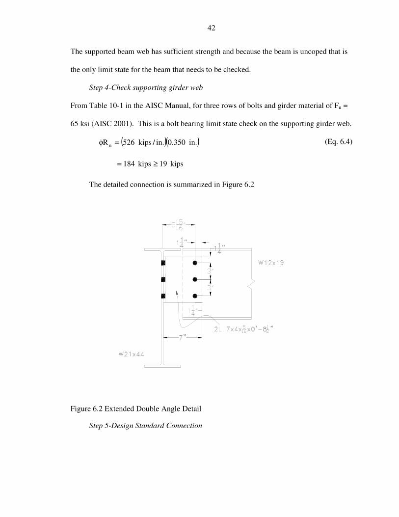
42
The supported beam web has sufficient strength and because the beam is uncoped that is
the only limit state for the beam that needs to be checked.
Step 4-Check supporting girder web
From Table 10-1 in the AISC Manual, for three rows of bolts and girder material of Fu =
65 ksi (AISC 2001). This is a bolt bearing limit state check on the supporting girder web.
( )( ).in350.0.in/kips526R n =φ (Eq. 6.4)
kips19kips184 ≥=
The detailed connection is summarized in Figure 6.2
Figure 6.2 Extended Double Angle Detail
Step 5-Design Standard Connection

43
The design of the standard double angle connection is checked by MathCAD
worksheets (Green et al. 2001). The connection requires three 3/4-inch diameter bolts, in
order for the angle to be greater than half the T-depth of the beam.
kips19kips8.42R n ≥=φ (Eq. 6.5)
The controlling limit state is bolt bearing on the outstanding leg. The detail for the
connection can be seen in Figure 6.3.
Figure 6.3 Standard Double Angle Detail
6.2 Extended Single Angle Design Example
The following example is intended to show the use of the design tables in the
appendices to design an all-bolted extended single angle connection. The connection to
be designed is taken from the results of the parametric bay study. The problem statement
is given in the following paragraph.
Design the all-bolted single-angle shear connection shown in Figure 6.4. The
connection should be designed as an extended connection. Use A36 material for the
44
connection angles and 3/4 inch diameter A325 bolts. The connection is carrying a
factored load of 50 kips, which was determined using the parametric bay study
spreadsheet provided by AISC (AISC 2003). Lastly, draw a detail of the designed
connection.
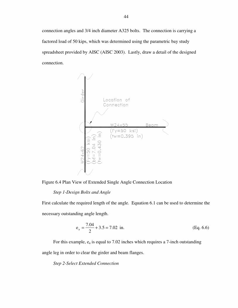
Figure 6.4 Plan View of Extended Single Angle Connection Location
Step 1-Design Bolts and Angle
First calculate the required length of the angle. Equation 6.1 can be used to determine the
necessary outstanding angle length.
.in02.75.3204.7
ea =+= (Eq. 6.6)
For this example, ea is equal to 7.02 inches which requires a 7-inch outstanding
angle leg in order to clear the girder and beam flanges.
Step 2-Select Extended Connection

45
Use the all-bolted extended single angle design tables and choose an appropriate
connection. Using the tables in Appendix G, a connection can be chosen. A 6-bolt
connection using a 3/8-inch thick A36 angle will work.
kips50kips2.58R n ≥=φ
(Eq. 6.7)
Step 3-Check supported beam web
From Table 10-1 in the AISC Manual, for six rows of bolts, beam material of Fy = 50 ksi
and Fu = 65 ksi, and Lev = 1.25 in. and Leh = 1.25 in., and the beam is uncoped (AISC
2001).
( )( ).in395.0.in/kips526R n =φ (Eq. 6.8)
kips50kips208 ≥=
The supported beam web has sufficient strength and because the beam is uncoped that is
the only limit state for the beam that needs to be checked.
Step 4-Check supporting girder web
From Table 10-1 in the AISC Manual, for six rows of bolts and girder material of Fy = 50
ksi and Fu = 65 ksi , using half the value because this is a single angle connection (AISC
2001)
( )( ).in430.0.in/kips105021R n =φ
(Eq. 6.9)
kips50kips226 ≥=
The detailed connection is summarized in Figure 6.5
46
Figure 6.5 Extended Single Angle Detail
Step 5-Design Standard Connection
The design of the standard single angle connection is checked by MathCAD
worksheets (Green et al. 2001). The connection requires only four 3/4-inch diameter
bolts, but the beam must be coped top and bottom in order to fit within the girder T-
dimension.
kips50kips6.63R n ≥=φ (Eq. 6.10)
The controlling limit state is bolt shear on the outstanding leg. The detail for the
connection can be seen in Figure 6.6.

47
Figure 6.6 Standard Single Angle Detail
6.3 Extended Tee Design Example
The following example is intended to show the use of the design tables in the
appendices to design an all-bolted extended tee connection. The connection to be
designed is taken from the results of the parametric bay study. The problem statement is
given in the following paragraph.
Design the all-bolted tee shear connection shown in Figure 6.7. The connection
should be designed as an extended connection. Use A992 material for the tee and 3/4
inch diameter A325 bolts. The connection is carrying a factored load of 19 kips which
was determined using the parametric bay study spreadsheet provided by AISC (AISC
2003). Lastly, draw a detail of the designed connection

48
Figure 6.7 Plan View of Extended Tee Connection Location
Step 1-Design Bolts and Tee
Calculate the required depth of the tee. Equation 6.1 can be used to determine the
necessary outstanding tee depth.
.in50.65.3200.6
ea =+= (Eq. 6.11)
For this example, ea is equal to 6.5 inches which requires a 7-inch deep tee in order
to clear the girder and beam flanges.
Step 2-Select Extended Connection
Use the all-bolted extended tee design tables and choose an appropriate connection.
Using the tables in Appendix M, a connection can be chosen. Choose a WT6x25, for this
connection. Now the stem thickness needs to be checked in order to determine which
row on the design table to use. The stem thickness for a WT6x25 is 0.37 inches,

49
therefore; use the highlighted row because the stem thickness is greater than the limiting
thickness of 0.36 inches. Assume the eccentricity to be 7 inches to be conservative.
kips19kips0.24R n ≥=φ (Eq. 6.12)
Step 3-Check supported beam web
From Table 10-1 in the AISC Manual, for four rows of bolts, beam material of Fy = 50
ksi and Fu = 65 ksi, and Lev = 1.25 in. and Leh = 1.25 in., and the beam is uncoped (AISC
2001).
( )( ).in230.0.in/kips409R n =φ (Eq. 6.13)
kips19kips0.94 ≥=
The supported beam web has sufficient strength and because the beam is uncoped that is
the only limit state for the beam that needs to be checked.
Step 4-Check supporting girder web
From Table 10-1 in the AISC Manual, for four rows of bolts and girder material of Fy =
50 and Fu = 65 ksi , (AISC 2001)
( )( ).in300.0.in/kips819R n =φ (Eq. 6.14)
kips19kips246 ≥=
The connection is summarized in Figure 6.8
Step 5-Design Standard Connection
The design of the standard tee connection is checked by MathCAD worksheets
(Green et al. 2001). The connection requires only three 3/4-inch diameter bolts, but the
beam must be coped
kips19kips1.39R n ≥=φ (Eq. 6.15)

50
The controlling limit state is bolt bearing on the tee stem. The detail for the
connection can be seen in Figure 6.9.
Figure 6.8 Extended Tee Detail
.
Figure 6.9 Standard Tee Connection

51
CHAPTER 7 FINITE ELEMENT ANALYSIS
7.1 Introduction
This chapter presents the results of a finite element study that was conducted on a
single angle bolted connection where the protruded leg of the angle extended beyond the
flange of the supporting girder. The behavior of the extended connection was compared
to that of a standard equal leg angle connection that would be used in a coped beam to
girder connection. The finite element model consisted of three main parts: the
connection angle, bolts and a portion of the supporting girder web. Each of these parts
was modeled with three-dimensional (3D) solid elements. Additionally, the contact
surface between connected elements, e.g. angle and girder web were modeled. The finite
element model incorporated the effects of material and geometric nonlinearity as well as
including the effect of initial bolt pretension on the overall connection behavior.
The finite element analysis was carried out using the latest commercially available
ADINA finite element software package, Version 8.1 (ADINA 2003). This finite
element package has the capability to model complex phenomena such as contact
problems, initial stresses, non-linear material and geometric behavior as well as dynamic
analysis. The user inputs the geometry as a 3D model drawn in a Computer Aided
Design (CAD) environment. Then, after specifying the desired type of element(s) and
mesh density, the program automatically generates an optimal finite element mesh.
Once the analytical model is generated the analysis results can be presented in
numerous graphs and plots showing critical behaviors that are identified such as the

52
applied load-vertical tip displacement behavior and the effective stresses occurring
throughout the model. The basic finite element model was created where the position of
the bolt line in the in-plane angle leg corresponded to that of a standard coped beam to
girder connection. The finite element model was then modified by adding additional
elements to the in-plane angle leg to account for the bolt line being located further away
from the girder web. This model represented the protruded angle leg of an extended
connection where the supported beam would not need to be coped prior to being
connected to the supporting girder. The material strengths used in the models for the
structural shapes consisted of both A36 and A572 Gr. 50 steel. Therefore, the material
steel strength was considered a model parameter. The finite element analysis results for
the various models are compared as well as to the current design procedures that are in
the AISC Manual of Steel Construction (AISC 2001).
7.2 Finite Element Model Development
7.2.1 FE Discretization for Angle
Three-dimensional (3D) solid elements were utilized to model the angle section.
These elements are 8-node elements as described in the ADINA Theory and Modeling
Guide (ADINA 2003). Each node in the solid element has three master degrees of
freedom: X-translation, Y-translation, and Z-translation. The basic finite element mesh
for the angle contained 5830 solid elements and 6320 nodes. The angle mesh detail is
shown in Figure 7.1. The angle section used in the basic model represented a L3½ x 3½
x 5/16 and was 9 inches long. This length was chosen since it is representative of a
standard three-bolt shear connection with 1½ in. edge spacing and 3 in. center-to-center
spacing of the bolts. The 3½ inch protruded leg in the basic model was extended to 5
inches in the modified finite element model.

53
The basic and modified models were developed for a three-bolt connection. A
standard bolt hole diameter was used in each of the models and consisted of holes that
had a 0.8125 inch diameter for ¾ inch diameter bolts.
Following a convergence study of the contact problem between the bolts and the
bolt holes, it was determined that four elements would be necessary through the thickness
of the angle leg (Wheeler et al. 2000). Since there were no bolt holes modeled in the
protruded leg, only two elements were used through the thickness in order to decrease the
number of elements used in the finite element mesh of the angle (Mao et al. 2001). A
convergence study was also carried out to determine the required element size to be used
to model the angle section. Three mesh sizes, a coarse, fine, and extra fine mesh were
created with average element sizes of 0.4, 0.3, and 0.2 inches, respectively, along the top
and bottom edges of the angle. It was determined, from the convergence study, that it
would be necessary to use the extra fine mesh in modeling the angle section. Therefore,
with this mesh size thirty elements were generated around the circumference of each of
the bolt holes.
7.2.2 FE Discretization for Girder
Modeling of the supporting girder was simplified to that of modeling its web in
order to decrease the number elements used in the overall finite element model. Three-
dimensional (3D) solid elements were utilized to model the web of the girder, the same
type of elements used to model the angle section. The basic finite element mesh for the
girder web contained 5296 solid elements and 5834 nodes. The girder web was
constructed as a plate with a width of 5½ inches, height of 11 inches and a thickness of
5/16 inches. The mesh detail is shown in Figure 7.1.

54
Three bolt holes were modeled in the web of girder to correspond with the three
bolt holes in the angle. The diameter of these bolt holes was also 0.8125 inches.
Following the same convergence study of the contact problem between the bolts and the
bolt holes, it was determined that four elements would be required through the thickness
of the girder web.
Similar to the angle mesh convergence study, three different element sizes were
considered for the girder web mesh. The average element sizes that were evaluated had
dimensions of 0.4, 0.3 and 0.25 inches. Based on the results of the study, the 0.25 inch
element size was chosen for the girder web mesh. Also, in order to match the mesh of
the angle section that was connected to the web of the girder, thirty elements were
generated around the circumference of each of the bolt holes.
7.2.3 FE Discretization for Bolts
High strength structural ASTM A325 and A490 bolts were included as part of the
finite element model. The two types of bolts were each modeled in a similar fashion, the
only difference being their material behavior. Depending on the type of bolt used in the
model, a minimum pretension could be applied to the bolt in accordance with the AISC-
LRFD Specification (AISC 1999). Three-dimensional (3D) solid elements were utilized
to model each of the three bolts. These elements were 8-node elements as described in
the ADINA Theory and Modeling Guide (ADINA 2003) with three master displacement
degrees of freedom per node. The basic finite element mesh for the three bolts included
10251 elements and 11685 nodes. The bolt mesh detail is shown in Figure 7.1.
The diameter of each bolt that was modeled was ¾ inch while the diameter of each
bolt head was 1¼ inch. In addition to the bolt and the bolt head being modeled, the nut
was also included as part of the finite element model. Along the body of the bolt, eight

55
elements were modeled in order to match the four elements through the thickness of the
angle leg and the other four elements through the thickness of the girder web. Four
elements were generated through the thickness of the bolt head and the nut. In order to
match the angle and girder web mesh, thirty elements were constructed around the body
of the bolt, the bolt head and the nut.
7.3 FE Model Contact Conditions
A contact condition can be specified in ADINA to model the contact behavior
between solid elements and other structural elements such as the truss, beam, shell, plate
and pile elements. Since only 3D solid elements were utilized in the model, the contact
group that was used in the model was the 3D contact group. In this type of contact group,
one of the two contact surfaces that formed is called the contactor surface and the other is
called the target surface. During the loading of the finite element model the two contact
surfaces are expected to come into contact and become a contact pair.
All parts of the bolted-bolted shear connection are connected to each other through
the contact condition. When the applied load from the beam is imparted to the angle, the
angle begins to displace which then causes it to come into contact with the bolts. The
displacement of the outstanding leg of the angle in turn then causes the bolts to come into
contact with the girder. When the bolts are also pretensioned, the bolt heads are brought
into contact with the in-plane leg of the angle, the nuts are brought into contact with the
girder web and the facing elements of the in-plane angle leg and the girder web are
brought into contact prior to the load being applied to the model.
The contact surfaces as described above were defined as surfaces that were initially
in contact or were anticipated to come into contact by the pretensioning of the bolts or
during the application of the load. In order to avoid an overconstrained analysis problem
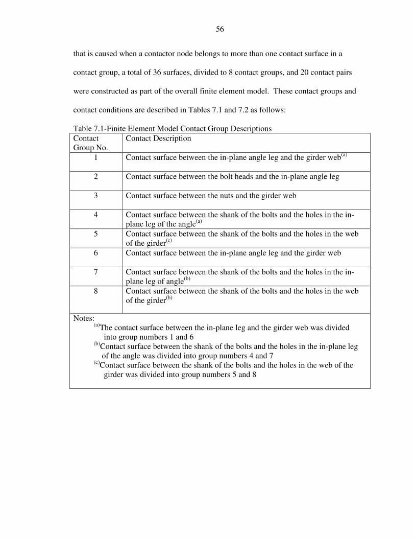
56
that is caused when a contactor node belongs to more than one contact surface in a
contact group, a total of 36 surfaces, divided to 8 contact groups, and 20 contact pairs
were constructed as part of the overall finite element model. These contact groups and
contact conditions are described in Tables 7.1 and 7.2 as follows:
Table 7.1-Finite Element Model Contact Group Descriptions Contact Group No.
Contact Description
1 Contact surface between the in-plane angle leg and the girder web(a)
2 Contact surface between the bolt heads and the in-plane angle leg
3 Contact surface between the nuts and the girder web
4 Contact surface between the shank of the bolts and the holes in the in-plane leg of the angle(a)
5 Contact surface between the shank of the bolts and the holes in the web of the girder(c)
6 Contact surface between the in-plane angle leg and the girder web
7 Contact surface between the shank of the bolts and the holes in the in-plane leg of angle(b)
8 Contact surface between the shank of the bolts and the holes in the web of the girder(b)
Notes: (a)The contact surface between the in-plane leg and the girder web was divided into group numbers 1 and 6 (b)Contact surface between the shank of the bolts and the holes in the in-plane leg of the angle was divided into group numbers 4 and 7 (c)Contact surface between the shank of the bolts and the holes in the web of the girder was divided into group numbers 5 and 8

57
Table 7.2- Finite Element Model Contact Surface, Pair, and Group Interactions Contact Surface Number Contact pair
Contact Groups Number Position of Faces Number
Target Surface
Contactor Surface
Group 1 1 Face #12 on Body #4 1 2 1 2 Face #12 on Body #6
Group 2 1 Face #11 on Body #4 1 2 1 2 Face #6 on Body #8 2 3 1 3 Face #6 on Body #7 3 4 1 4 Face #6 on Body #9
Group 3 1 Face #11 on Body #6 1 1 2 2 Face #5 on Body #8 2 1 3 3 Face #5 on Body #7 3 1 4 4 Face #5 on Body #9
Group 4 1 Face #1 on Body #4 1 4 1 2 Face #2 on Body #4 2 5 2 3 Face #6 on Body #4 3 6 3 4 Face #7 on Body #8 5 Face #7 on Body #7 6 Face #7 on Body #9
Group 5 1 Face #9 on Body #6 1 1 4 2 Face #7 on Body #6 2 2 5 3 Face #10 on Body #6 3 3 6 4 Face #4 on Body #8 5 Face #4 on Body #7 6 Face #4 on Body #9
Group 6 1 Face #12 on Body #6 1 1 2 2 Face #6 on Body #2
Group 7 1 Face #10 on Body #4 1 4 1 2 Face #7 on Body #4 2 5 2 3 Face #9 on Body #4 3 6 3 4 Face #4 on Body #8 5 Face #4 on Body #7 6 Face #4 on Body #9
Group 8 1 Face #6 on Body #6 1 1 4 2 Face #2 on Body #6 2 2 5 3 Face #1 on Body #6 3 3 6 4 Face #7 on Body #8 5 Face #7 on Body #7 6 Face #7 on Body #9

58
Tables 7.1 and 7.2 describe the detailed interactions that occurred in the finite
element analysis. Table 7.1 gives the general description of the eight contact groups that
were included in the model. Table 7.2 gives the detailed interactions between the three
main components that were included in the model and are called Bodies. The girder web
included two Bodies that were numbered 3 and 6. The angle included five Bodies that
were numbered 1, 2, 4, 5 and 10. The bolts included three Bodies that corresponded to
the three bolts that numbered 7, 8 and 9. If no contact pair numbers given in the table
that means that these two surfaces did not come into contact during the analysis.
ADINA has a library of simple Bodies contained within ADINA-M that can be
specified for contact problems. If the Body is of a complex nature it needs to be modeled
by the user. In the bolted-bolted beam-to-girder finite element model that was created
only Body numbers 1 and 3 were taken from the ADINA-M library. The other Body
numbers were more complex and had to be developed from the simple Body definitions
provided in the software. For these remaining complex Bodies, ADINA assigned Face
numbers to each Body (e.g. the simple block Body has six Faces that are assigned Face
numbers 1 through 6). ADINA automatically assigned Face numbers to each complex
Body that was modeled such as the bolt shanks or the in-plane leg of the angle having
three bolt holes. Only through direct observation of the graphical ADINA output could
the automatically assigned Face numbers be identified.
An important distinction between a contactor surface and a target surface is that in
the converged finite element solution, the material overlap at the contactor nodes is zero
while the target nodes can overlap the contactor body (Bathe and Chaudhary 2000).
Therefore, the surfaces in the angle holes were formed as a contactor surface while the

59
surfaces on the bolts that are in contact with the angle holes were formed as the target
surface. On the other hand, the surfaces on the bolts that are in contact with the girder
web were assigned as the contactor surfaces while the surfaces in the girder web holes
were denoted as the target surface.
The model of the connection with pretensioned bolts meant that there was friction
between the in-plane leg of angle and the girder web. This friction along the contact
surface was handled in the model by assigning a compression force that acts on each
contactor node and that node is allowed to kinematically slide along the target segments
generating a tangential force that is equal to the Coulomb friction force (ADINA 2003).
In ADINA, the user only has to input a Coulomb friction coefficient in the model
definition of the contact group where it is to be considered and then the program
automatically determines the tangential force from the compression force based on the
following equation:
nt TT µ= (Eq. 7.1)
Where:
Tt = Tangential force
Tn = Normal force
µ = Coulomb friction coefficient
In the finite element model that was created only the friction between the in-plane
leg of angle and the girder web was considered. The Coulomb friction coefficient that
was assumed for this frictional contact was µ = 0.2. The frictional contact between the
bolt heads to the in-plane angle leg as well as the nuts to the girder web was not
considered. This modeling assumption was made since these contact surfaces had a

60
much smaller surface area than that of the in-plane angle leg being in contact with the
girder web. This assumption also helped to decrease the analysis run time and the
number of iterations that necessary for each time step to converge.
7.4 FE Model Initial Conditions
The three-bolt connection was pretensioned to assure that the leg of the angle was
brought into firm contact with the web of the girder before the vertical load was applied.
In order to accomplish this in the finite element model, an initial stress was applied to the
bolts to create the pretension. Following the ADINA-Theory and Modeling Guide
(ADINA 2003), the initial stress could be done by three different methods: nodal initial
strain, element initial strain or directly applying a pressure load. The direct pressure load
application method was selected because it was easy to apply and the magnitude of the
specified pressure load could be changed. Furthermore, the method accurately reflected
the behavior of the bolts when they are pretensioned, i.e. only the body of the bolt had a
pretension load, not the bolt heads or nuts.
In order to generate the bolt pretension, a pressure load was simultaneously applied
at each bolt head and nut. The pressure load that was applied to the ¾ inch diameter bolts
in the finite element model was 10 ksi. This initial condition was established in the first
step of the analysis. After that, in the second step, the pretension load was omitted and
the external vertical load was incrementally applied.
7.5 FE Model Applied Loading
A static analysis solution scheme was performed using ADINA on the finite
element model. This type of solution does not include time dependent effects, so the
specified time step increment in the program was used to define the increment or
intensity of each load step increment. In order to ensure convergence was achieved in the

61
solution, the number of time steps needed to be small and it was typical for the analysis
runs to use more than 350 time steps in each case.
The finite element model loading was carried out in two steps: Step 1 was
described in Section 7.4 where a pretension load was generated in the bolts, and Step 2 is
described in this section where the external vertical load was applied to the model. The
vertical shear load was applied incrementally from zero until a maximum value was
reached. This maximum load indicated that the bolted-bolted connection had reached its
ultimate load-carrying capacity.
The vertical shear load was transmitted from the beam into the connection angle
through the three bolts attaching it to the protruded leg. These three bolts were modeled
as three load groups and each group consisted of six single loads as shown in Figure 7.2.
The locations of where the vertical loads were applied were determined from the usual
geometry of where the bolt holes would have been if they had been modeled. These
locations in the protruded leg were at a horizontal distance of 2 inches from the heel of
the 3½ inch angle leg and 3½ inches from the heel of the 5 inch angle leg.
7.6 FE Model Boundary Conditions
There were two types of boundary conditions utilized in the model. The first type
of boundary condition was placed on the vertical edges of the girder web. Recall that its
model definition consisted of 8-node, 3D solid elements with three master degrees of
freedom at each node (X-, Y- and Z-translation). To simulate a fixed type boundary
condition, all the nodal translational degrees of freedom were fixed along these edges
which were away from the portion of the web where the angle was attached. This
boundary condition was generated along the two edges of the girder web that are parallel
to the Z-axis as shown in Figure 7.3.

62
The second boundary condition was placed on the protruded angle leg. In a real
bolted-bolted connection this protruded leg would be connected to the web of a beam, but
since this web was not modeled, a boundary condition was imposed to simulate this part
of the connection. The inherent stiffness in the connection between the web of the beam
and the protruded angle leg would restrain this part of the connection from twisting or
moving in the X-direction. Therefore, the X-direction movement of the angle was fixed
through the use of a boundary condition imposed on every node that made up the exterior
face of the protruded angle leg. This boundary condition can be seen in Figure 7.3.
7.7 FE Model Material Behavior
The inelastic material behavior of the angle, girder web and bolts were considered
in the finite element model development. Two steel material types, A36 (ASTM 2003?)
and A572 Gr. 50 (ASTM 2003?) were assigned to the angle while only one type of steel
material, A572 Gr. 50 was assigned to the girder web. Again, there were two steel
material types assigned to the bolts – either A325 (ASTM 2003?) or A490 (ASTM
2003?). No material coupon tests or bolt tests were conducted for this project so it was
decided that a reasonable way to incorporate the inelastic behavior of the steel materials
was to treat each type as having a bi-linear stress-strain curve (Salmon and Johnson
1996). Regardless of the type of steel material, the Modulus of Elasticity, E, was defined
as having a value of 29,000 ksi. The stress-strain relationships provided in the ADINA
FE models for the A36 steel, A572 Gr. 50 steel, A325 bolt steel and A490 bolt steel are
given in Figures 7.4 through7.7. All of the material bi-linear curves are comprised of two
straight line segments. The first portion represents the elastic behavior and goes from
zero to a point defined by the yield strain and the corresponding yield stress of the
material, (εy , σy). The second portion represents the inelastic behavior of the material.

63
This part of the stress-strain curve starts at (εy , σy) and is terminated at a point defined
by the ultimate strain and the corresponding ultimate tensile strength of the material, (εu ,
σu). It was felt that this level of strain would not be exceeded in any of the analyses so
the stress-strain curves did not need to be extended any further than that provided.
Table 7.3 FE Model Steel Material Properties ASTM
Designation Yield Stress,
σy (ksi) Ultimate Tensile Strength, σu (ksi)
A36 36 58 A572 Gr. 50 50 65
A325 80 100 A490 100 120
Finally, the steel materials for the angle and girder web along with the different bolt
types were arranged into groups and analyzed as shown in the Table 7.4.
Table 7.4 FE Model Material Groups Angle Girder Web Bolt
Group I A36 A572 A490 Group II A36 A572 A325 Group III A572 A572 A490
7.8 FE Analysis Results
The results from each FE model were post-processed through ADINA-Plot, a
branch of the ADINA finite element software package, Version 8.1 (ADINA 2003). In
order to compare the analysis results from different model configurations a consistent
approach to the data would need to be taken. It was decided that the best way to do this
would be to either: 1) Plot the incremental applied load versus the tip deflection of the
protruded angle leg from different FE models; or 2) Plot the incremental applied load
versus the end rotation of the protruded angle leg from different FE models. The end
rotation of the leg was calculated from the displacement results taken at two nodes on the

64
toe of the protruded leg. The first node was located at the top corner and the second node
was located at the bottom corner of the protruded leg. The node numbers from the two
different geometric models that were used to determine the end rotation of the angle leg
are shown in the Table 7.5.
Table 7.5 Corner Node Numbering Model Description Top Corner Node Bottom Corner Node
3½ in. Protruded Leg Model 24703 22556 5 in. Protruded Leg Model 27719 22591
The end rotation, �, of the protruded leg from each analysis result was calculated
using the following the equation:
( )( )topbottom
bottomtop
ZZ.in9
YY
−+−
=θ (Eq. 7.2)
Where:
Ytop = Displacement of the top corner node in the Y-axis
Ybottom = Displacement of the bottom corner node in the Y-axis
Ztop = Displacement of the top corner node in the Z-axis
Zbottom = Displacement of the bottom corner node in the Z-axis
9 in. = Length of the angle
It was necessary to take into account both the Y-axis displacement as well as the Z-axis
displacement in the calculation of end rotation since the protruded angle leg did not
deform solely in its own plane. Figure 7.8 shows the load vs. displacement results of the
Material Group I finite element model with a 5 inch protruded leg where the maximum
displacements reached 0.36 and 0.23 inches in the Y- and Z-axis, respectively when the
maximum applied load reached 34.8 kips. This occurred at time step = 193.

65
The applied load vs. end rotation was compared for two Material Group I models
that only differed in the length of the protruded angle leg (see Figure 7.9). The model
with the 3½ inch protruded leg converged at time step = 277, corresponding to a
maximum applied load of 49.9 kips and an end rotation of 0.054 rad. The model with the
5 inch protruded leg converged at time step = 193, corresponding to a maximum applied
load of 34.8 kips and an end rotation of 0.053 rad.
The next applied load vs. end rotation comparison that was made evaluated the
results from the Material Group I (A490 bolts) and II (A325 bolts) models. The length of
the protruded angle leg in each model was 5 inches. The model with the A325 bolts
reached a convergence limit when time step = 194, corresponding to a maximum applied
load of 35.0 kips and an end rotation of 0.058 rad. In comparison, the model with the
A490 bolts converged at time step = 193, corresponding to a maximum applied load of
34.8 kips and an end rotation of 0.053 rad. The results of this comparison are shown in
Figure 7.10.
The last applied load vs. end rotation comparison that was made evaluated the
results from the Material Group I (A36 angle) and III (A572 Gr. 50 angle) models. The
length of the protruded angle leg in each model was 5 inches. The model with the A36
steel angle reached a convergence limit when time step = 193, corresponding to a
maximum applied load of 34.8 kips and an end rotation of 0.053 rad. In comparison, the
model with the A572 Gr. 50 steel angle converged at time step = 240, corresponding to a
maximum applied load of 43.2 kips and an end rotation of 0.066 rad. Figure 7.11 shows
the comparison between these two analysis results.

66
Figures 7.12 and 7.13 are smoothed effective stress plots showing the change in
model behavior from the initial time step to the final time step, respectively of the
analysis run with Material Group I and a 3½ inch protruded angle leg. At time step =
1.000 there was no externally applied load, only the pretension in the bolts. The
maximum smoothed effective stress was approximately 14 ksi and that was fairly
uniform between the angle, girder web and the bolts. At time step = 193, the maximum
smoothed effective stresses were 65.78 ksi in the angle, 88.14 ksi in the girder web and
132.6 ksi on the bolt shank. The critical stress occurred at the location of the top hole in
the angle leg. This would correspond to reaching a limit state of bolt bearing on the angle
material which is the same limit state that would have been found if using the design
tables in the Appendices.
Figures 7.14 and 7.15 show the maximum smoothed effective stress plots for
analysis runs with Material Groups II and III, respectively and a 3½ inch protruded angle
leg. For Material Group II (time step = 194) these stresses were 70.05 ksi in the angle,
88.11 in the girder web and 98.30 ksi on the bolt shank. For Material Group III (time
step = 240) these stresses were 78.91 ksi in the angle, 99.95 ksi in the girder web and
136.8 ksi on the bolt shank. In each case the maximum stress occurred at one of the bolt
hole locations indicating that a limit state of bolt bearing was reached.
One more comparison was made between all the models previously discussed and a
new model where the boundary condition along the vertical edges of the girder web was
changed from being fixed to that of being pinned. Figure 7.16 shows the applied load vs.
end rotation behavior of the new model compared to all the previous results. The pinned
boundary condition has a marked influence on the rotational behavior of the connection

67
whereas the strength of the connection only changed slightly. A convergence limit was
reached in the analysis of this model at time step = 207, corresponding to an applied load
of 37.2 kips and a maximum end rotation of 0.129 rad. Again, the maximum stresses
occurred at the top bolt hole location, but now it was bolt bearing on the girder web.

68
Figure 7.1 FE Model Element Meshing

69
Figure 7.2 FE Model Applied Loading

70
Figure 7.3 FE Model Boundary Conditions

71
Stress-Strain Curve
0.0
36.0
58.0
0.0
10.0
20.0
30.0
40.0
50.0
60.0
70.0
0.000 0.050 0.100 0.150 0.200
Strain
Str
ess
(ksi
)
Stress
Figure 7.4 Bi-linear Stress-Strain Curve for A36 Steel Material
Stress-Strain Curve
0.0
50.0
65.0
0.0
10.0
20.0
30.0
40.0
50.0
60.0
70.0
0.000 0.050 0.100 0.150 0.200
Strain
Str
ess
(ksi
)
Stress
Figure 7.5 Bi-linear Stress-Strain Curve for A572 Gr. 50 Steel Material

72
Stress-Strain Curve
0.0
100.0
80.0
0.0
20.0
40.0
60.0
80.0
100.0
120.0
0.000 0.050 0.100 0.150 0.200
Strain
Str
ess
(ksi
)
Stress
Figure 7.6 Bi-linear Stress-Strain Curve for A325 Bolt Material
Stress-Strain Curve
0.0
120.0
100.0
0.0
20.0
40.0
60.0
80.0
100.0
120.0
140.0
0.000 0.050 0.100 0.150 0.200
Strain
Str
ess
(ksi
)
Stress
Figure 7.7 Bi-linear Stress-Strain Curve for A490 Bolt Material

73
Load-Displacement Curve
0.0
5.0
10.0
15.0
20.0
25.0
30.0
35.0
40.0
0.000 0.050 0.100 0.150 0.200 0.250 0.300 0.350 0.400
Displacement (in.)
Load
(Kip
)
Z Displacement Y Displacement
Figure 7.8 Applied Load vs. Horizontal Z- and Vertical Y- Tip Displacement of FE Model with 5 in. Protruded Angle Leg and Material Group I
Load-Rotation Curve
0.0
10.0
20.0
30.0
40.0
50.0
60.0
0 0.01 0.02 0.03 0.04 0.05 0.06
Rotation (rad)
Load
(Kip
)
5in Protruded Leg 3.5in Protruded Leg
Figure 7.9 Comparison of Applied Load vs. End Rotation Curves for FE Models with 3.5 and 5 in. Protruded Legs and Material Group I

74
Load-Rotation Curve
0.0
5.0
10.0
15.0
20.0
25.0
30.0
35.0
40.0
0 0.01 0.02 0.03 0.04 0.05 0.06 0.07
Rotation (rad)
Load
(Kip
)
A490 Bolt Used A325 Bolt Used
Figure 7.10 Comparison of Applied Load vs. End Rotation Curves for FE Models with A325 and A490 Bolts and 5 in. Protruded Leg
Load-Rotation Curve
0.0
5.010.0
15.0
20.025.0
30.0
35.0
40.045.0
50.0
0 0.01 0.02 0.03 0.04 0.05 0.06 0.07
Rotation (rad)
Load
(Kip
)
A36 Angle Used " A572 Angle Used"
Figure 7.11 Comparison of Applied Load vs. End Rotation Curves for FE Models with A36 and A572 Gr. 50 Angles and 5 in. Protruded Leg

75
Figure 7.12 Effective Stress Plots of the Single Angle, Bolts and Girder Web for the FE Model with 3.5 in. Protruded Leg and
Material Group I, Time Step = 1.000
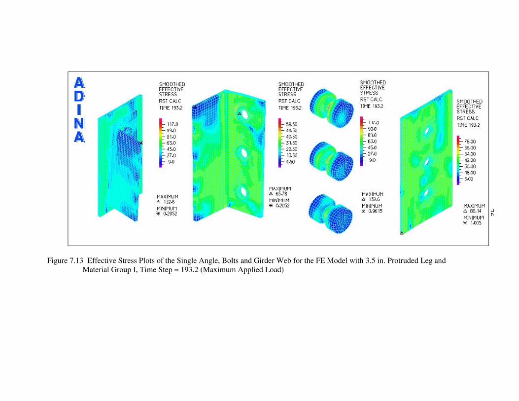
76
Figure 7.13 Effective Stress Plots of the Single Angle, Bolts and Girder Web for the FE Model with 3.5 in. Protruded Leg and Material Group I, Time Step = 193.2 (Maximum Applied Load)

77
Figure 7.14 Effective Stress Plots of the Single Angle, Bolts and Girder Web for the FE Model with 3.5 in. Protruded Leg and
Material Group II, Time Step = 193.8 9 (Maximum Applied Load)

78
Figure 7.15 Effective Stress Plots of the Single Angle, Bolts and Girder Web for the FE Model with 3.5 in. Protruded Leg and
Material Group III, Time Step = 239.62 (Maximum Applied Load)
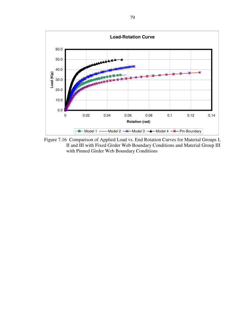
79
Load-Rotation Curve
0.0
10.0
20.0
30.0
40.0
50.0
60.0
0 0.02 0.04 0.06 0.08 0.1 0.12 0.14
Rotation (rad)
Load
(Kip
)
Model 1 Model 2 Model 3 Model 4 Pin-Boundary
Figure 7.16 Comparison of Applied Load vs. End Rotation Curves for Material Groups I, II and III with Fixed Girder Web Boundary Conditions and Material Group III with Pinned Girder Web Boundary Conditions

80
CHAPTER 8 SUMMARY AND CONCLUSIONS
Extended all-bolted double angle, single angle, and tee connections are a viable
alternative to standard shear connections with coped beams. The connections have a
limited range of applicability, but in low-rise commercial buildings with lightly loaded
bays, an extended connection will be economical. The connections require no new
construction methods or material, so they can be put to use immediately. The
introduction of longer leg or higher yield strength will increase the range where extended
all-bolted connections can be used.
The tables located in the appendices of this document are considered reliable for
design use. The methods that are used to tabulate them are all based on sound theory and
mechanics. It is recommended that before extended all-bolted connections are introduced
into common practice that some confirmatory laboratory testing be conducted. The
results from this testing may require modifications to the assumptions made in the
calculation of the design tables.
Also, more testing is recommended in the area of beam-to-girder connections.
Almost all previous research is oriented towards beam-to-column connections. The
behavior of a beam-to-girder connection will almost certainly vary somewhat from that of
a beam-to-column connection. Beam-to-girder connections are usually made to the web
of the girder and the web of the beam while beam-to column connections connect the
column flange to the beam girder. The stiffnesses between the girder web and the
column flange vary. This may affect the overall connection behavior. This insight may

81
help with the design of extended connections. Also, the differences between two-sided
connections as with interior girders where there is one connection on either side of the
girder web, and one-sided connections to spandrel girders should be considered during
the testing of beam-to-girder connections.
The design of extended all-bolted double angle, single angle, and tee connections
must be carefully considered. The designer should understand the theory and mechanics
that are involved in the design of these connections. The tables located in the appendices
section are only tools and designers should use their best judgment when selecting the
type of connection to be specified..

82
LIST OF REFERENCES
ADINA 8.1 (2003) Theory and Modeling Guide ARD 03-7. ADINA R&D Inc, Watertown, Mass. Ameican Institute of Steel Construction (AISC) (1999) Load and Resistance Factor Design Specification for Structural Steel Buildings. AISC, Chicago, Ill. Ameican Institute of Steel Construction (AISC) (2001) Manual of Steel Construction LRFD. 3rd Edition, AISC, Chicago, Ill. Ameican Institute of Steel Construction (AISC) (2003) “Parametric Bay Studies 4.1” Excel Spreadsheet updated 03/06/2003 at www.aisc.org, AISC, Chicago, Ill. Astaneh, A. (1989) “Demand and Supply of Ductility in Steel Shear Connections.” Journal of Constructional Steel Research. 14, 1-19. Astaneh, A. and Nader, M. N. (1990) “Experimental Studies and Design of Steel Tee Shear Connections.” Journal of Structural Engineering. 116(10), 2882-2902. American Society for Testing and Materials (ASTM) (2003a) A36/A36M-04 “Standard Specification for Carbon Structural Steel.” Annual Book of ASTM Standards. Volume 01.04. American Society for Testing and Materials (ASTM) (2003b) A325-04a “Standard Specification for Structural Bolts, Steel, Heat Treated, 120/105 ksi Minimum Tensile Strength.” Annual Book of ASTM Standards. Volume 01.08. American Society for Testing and Materials (ASTM) (2003c) A490-04a “Standard Specification for Structural Bolts, Alloy Steel, Heat Treated, 150 ksi Minimum Tensile Strength.” Annual Book of ASTM Standards. Volume 01.08. American Society for Testing and Materials (ASTM) (2003d) A992/A992M-04 “Standard Specification for Structural Steel Shapes.” Annual Book of ASTM Standards. Volume 01.04. American Society for Testing and Materials (ASTM) (2003e) F1852-04a “Standard Specification for Twist Off Type Tension Control Structural Bolt/Nut/Washer Assemblies, Steel, Heat Treated, 120/105 ksi Minimum Tensile Strength.” Annual Book of ASTM Standards. Volume 01.08.

83
Bathe, K. and Chaudhary A. (2000) “A Solution Method for Planar and Axisymmetric Contact Problems.” International Journal for Numerical Methods in Engineering. Vol. 21, 65-88. Changshi, M., Ricles, J., Lu, L. W., and Fisher, J. (2001) ”Effect of Local Details on Ductility of Welded Moment Connection.” Journal of Structural Engineering. 127(9), 1036-1044. Chen, W. F. and Lui, E. M. (1988) “ Static Web Moment Connections.” Journal of Constructional Steel Research. 10, 89-131. Cheng, J. J. R., (1993) “Design of Steel Beams with End Copes.” Journal of Constructional Steel Research. 25, 3-22. Cheng, J. J. R., Yura, J. M., and Johnson, C. P. (1988) “Lateral Buckling of Coped Steel Beams.” Journal of Structural Engineering. 114(1), 1-15. Green, P.S., Sputo, T., and Veltri, P. (2003). Connections Teaching Toolkit: A Teaching Guide for Structural Steel Connections. Chicago, Ill. Kennedy, D. J. L., (1969) “Moment-Rotation Characteristics of Shear Connections.” AISC Engineering Journal. AISC, 6(4), 105-115. Kishi, N. and Chen, W. F. (1990) “Moment-Rotation Relations of Semirigid Connections with Angles.” Journal of Structural Engineering. 111(7), 1813-1834. Kishi, N., Chen, W. F., Matsuoka, K. G., and Nomachi, S. G. (1987) “Moment-Rotation Relation of Single/Double Web-Angle Connections.” Proc., 1st International Workshop on Connections in Steel Structures: Behavior, Strength, and Design. Cachan, France, 135-149. Kulak, G., Fisher, J., and Struik, J. (1987) Guide to Design Criteria for Bolted and Riveted Joints. John Wiley & Sons, Inc., New York, New York. Research Council on Steel Connections (RCSC) (2000) Specification for Structural Joints Using ASTM A325 or A490 Bolts. AISC, Chicago, Ill. Salomon, C. and Johnson, J. (1996) Steel Structures: Design and Behavior.4th Edition. Harper Collins, New York, New York. Thorton, W. A. (1996), “A Rational Approach to Design of Tee Shear Connections.” Engineering Journal. 33(1), 34-37. Wheeler, A. T., Clarke, M. J., and Hancock, G. J. (2000) “Finite Element Modeling of Four Bolt, Tubular Moment End-Plate Connection.” Journal of Structural Engineering. 126(7), 816-822.

84
Yam, M. C. H., Lam, A. C. C., Iu, V. P., and Cheng, J. J. R. (2003) “Local Web Buckling Strength of Coped Steel I Beams.” Journal of Structural Engineering. 129(1), 3-11.

85
APPENDIX A 3/4-INCH DIAMETER ALL-BOLTED A36 STEEL DOUBLE ANGLE
CONNECTIONS
The tables given in Appendix A are all-bolted double angle connections. The
angles are A36 angles using either A325/F1852 or A490 3/4-inch diameter bolts.

86
Notes: Angles are assumed to be A36 Steel Supporting and supported members are assumed to be A992 Steel Leh is assumed to be 1.25 in. Represents a bolt bearing limit state Represents a bolt shear limit state Represents a slip-critical limit state All-Bolted Extended Double-Angle Connections
N (# of Bolts)
Bolt Diameter
Angle Outstanding
Leg
ASTM Desig.
Thread Condition
Hole Type
Angle Thickness
5/16 3/8 1/2 N 14.9 17.3 17.3 X 14.9 17.9 21.6 STD 11.3 11.3 11.3 OVS 9.7 9.7 9.7
SC Class A
SSLT 9.7 9.7 9.7 STD 14.9 17.2 17.2 OVS 13.8 14.6 14.6
A325/ F1852
SC Class B
SSLT 14.6 14.6 14.6 N 14.9 17.9 21.6 X 14.9 17.9 23.9 STD 14.2 14.2 14.2 OVS 12.0 12.0 12.0
SC Class A
SSLT 12.0 12.0 12.0 STD 14.9 17.9 21.5 OVS 13.8 16.6 18.2
2 3/4 6
A490
SC Class B
SSLT 14.9 17.9 18.2 All-Bolted Extended Double-Angle Connections
N (# of Bolts)
Bolt Diameter
Angle Outstanding
Leg
ASTM Desig.
Thread Condition
Hole Type
Angle Thickness
5/16 3/8 1/2 N 33.3 38.6 38.6 X 33.3 40.0 48.3 STD 25.3 25.3 25.3 OVS 21.6 21.6 21.6
SC Class A
SSLT 21.6 21.6 21.6 STD 33.3 38.4 38.4 OVS 30.9 32.6 32.6
A325/ F1852
SC Class B
SSLT 32.6 32.6 32.6 N 33.3 40.0 48.3 X 33.3 40.0 53.4 STD 31.6 31.6 31.6 OVS 26.9 26.9 26.9
SC Class A
SSLT 26.9 26.9 26.9 STD 33.3 40.0 48.0 OVS 30.9 37.1 40.7
3 3/4 6
A490
SC Class B
SSLT 33.3 40.0 40.7

87
Notes: Angles are assumed to be A36 Steel Supporting and supported members are assumed to be A992 Steel Leh is assumed to be 1.25 in. Represents a bolt bearing limit state Represents a bolt shear limit state Represents a slip-critical limit state All-Bolted Extended Double-Angle Connections
N (# of Bolts)
Bolt Diameter
Angle Outstanding
Leg
ASTM Desig.
Thread Condition
Hole Type
Angle Thickness
5/16 3/8 1/2 N 57.7 66.7 66.7 X 57.7 69.2 83.5 STD 43.8 43.8 43.8 OVS 37.3 37.3 37.3
SC Class A
SSLT 37.3 37.3 37.3 STD 57.7 66.4 66.4 OVS 53.5 56.4 56.4
A325/ F1852
SC Class B
SSLT 56.4 56.4 56.4 N 57.7 69.2 83.5 X 57.7 69.2 92.3 STD 54.7 54.7 54.7 OVS 46.6 46.6 46.6
SC Class A
SSLT 46.6 46.6 46.6 STD 57.7 69.2 83.0 OVS 53.5 64.2 70.5
4 3/4 6
A490
SC Class B
SSLT 57.7 69.2 70.5 All-Bolted Extended Double-Angle Connections
N (# of Bolts)
Bolt Diameter
Angle Outstanding
Leg
ASTM Desig.
Thread Condition
Hole Type
Angle Thickness
5/16 3/8 1/2 N 84.4 97.6 97.6 X 84.4 101.3 122.2 STD 64.2 64.2 64.2 OVS 54.6 54.6 54.6
SC Class A
SSLT 54.6 54.6 54.6 STD 84.4 97.1 97.1 OVS 78.3 82.6 82.6
A325/ F1852
SC Class B
SSLT 82.6 82.6 82.6 N 84.4 101.3 122.2 X 84.4 101.3 135.1 STD 80.1 80.1 80.1 OVS 68.2 68.2 68.2
SC Class A
SSLT 68.2 68.2 68.2 STD 84.4 101.3 121.4 OVS 78.3 93.9 103.2
5 3/4 6
A490
SC Class B
SSLT 84.4 101.3 103.2

88
Notes: Angles are assumed to be A36 Steel Supporting and supported members are assumed to be A992 Steel Leh is assumed to be 1.25 in. Represents a bolt bearing limit state Represents a bolt shear limit state Represents a slip-critical limit state All-Bolted Extended Double-Angle Connections
N (# of Bolts)
Bolt Diameter
Angle Outstanding
Leg
ASTM Desig.
Thread Condition
Hole Type
Angle Thickness
5/16 3/8 1/2 N 112.8 130.5 130.5 X 112.8 135.4 163.3 STD 85.7 85.7 85.7 OVS 73.0 73.0 73.0
SC Class A
SSLT 73.0 73.0 73.0 STD 112.8 129.8 129.8 OVS 104.6 110.3 110.3
A325/ F1852
SC Class B
SSLT 110.3 110.3 110.3 N 112.8 135.4 163.3 X 112.8 135.4 180.5 STD 107.1 107.1 107.1 OVS 91.1 91.1 91.1
SC Class A
SSLT 91.1 91.1 91.1 STD 112.8 135.4 162.3 OVS 104.6 125.5 137.8
6 3/4 6
A490
SC Class B
SSLT 112.8 135.4 137.8 All-Bolted Extended Double-Angle Connections
N (# of Bolts)
Bolt Diameter
Angle Outstanding
Leg
ASTM Desig.
Thread Condition
Hole Type
Angle Thickness
5/16 3/8 1/2 N 142.6 164.9 164.9 X 142.6 171.1 206.4 STD 108.4 108.4 108.4 OVS 92.3 92.3 92.3
SC Class A
SSLT 92.3 92.3 92.3 STD 142.6 164.1 164.1 OVS 132.2 139.4 139.4
A325/ F1852
SC Class B
SSLT 139.4 139.4 139.4 N 142.6 171.1 206.4 X 142.6 171.1 228.1 STD 135.3 135.3 135.3 OVS 115.1 115.1 115.1
SC Class A
SSLT 115.1 115.1 115.1 STD 142.6 171.1 205.1 OVS 132.2 158.7 174.2
7 3/4 6
A490
SC Class B
SSLT 142.6 171.1 174.2

89
Notes: Angles are assumed to be A36 Steel Supporting and supported members are assumed to be A992 Steel Leh is assumed to be 1.25 in. Represents a bolt bearing limit state Represents a bolt shear limit state Represents a slip-critical limit state All-Bolted Extended Double-Angle Connections
N (# of Bolts)
Bolt Diameter
Angle Outstanding
Leg
ASTM Desig.
Thread Condition
Hole Type
Angle Thickness
5/16 3/8 1/2 N 172.1 199.0 199.0 X 172.1 206.5 249.0 STD 130.8 130.8 130.8 OVS 111.4 111.4 111.4
SC Class A
SSLT 111.4 111.4 111.4 STD 172.1 198.0 198.0 OVS 159.6 168.3 168.3
A325/ F1852
SC Class B
SSLT 168.3 168.3 168.3 N 172.1 206.5 249.0 X 172.1 206.5 275.3 STD 163.3 163.3 163.3 OVS 138.9 138.9 138.9
SC Class A
SSLT 138.9 138.9 138.9 STD 172.1 206.5 247.5 OVS 159.6 191.5 210.3
8 3/4 6
A490
SC Class B
SSLT 172.1 206.5 210.3 All-Bolted Extended Double-Angle Connections
N (# of Bolts)
Bolt Diameter
Angle Outstanding
Leg
ASTM Desig.
Thread Condition
Hole Type
Angle Thickness
5/16 3/8 1/2 N 202.0 233.6 233.6 X 202.0 242.4 292.3 STD 153.5 153.5 153.5 OVS 130.7 130.7 130.7
SC Class A
SSLT 130.7 130.7 130.7 STD 202.0 232.4 232.4 OVS 187.3 197.5 197.5
A325/ F1852
SC Class B
SSLT 197.5 197.5 197.5 N 202.0 242.4 292.3 X 202.0 242.4 323.2 STD 191.7 191.7 191.7 OVS 163.1 163.1 163.1
SC Class A
SSLT 163.1 163.1 163.1 STD 202.0 242.4 290.5 OVS 187.3 224.8 246.8
9 3/4 6
A490
SC Class B
SSLT 202.0 242.4 246.8

90
Notes: Angles are assumed to be A36 Steel Supporting and supported members are assumed to be A992 Steel Leh is assumed to be 1.25 in. Represents a bolt bearing limit state Represents a bolt shear limit state Represents a slip-critical limit state All-Bolted Extended Double-Angle Connections
N (# of Bolts)
Bolt Diameter
Angle Outstanding
Leg
ASTM Desig.
Thread Condition
Hole Type
Angle Thickness
5/16 3/8 1/2 N 231.6 267.8 267.8 X 231.6 277.9 335.1 STD 176.0 176.0 176.0 OVS 149.9 149.9 149.9
SC Class A
SSLT 149.9 149.9 149.9 STD 231.6 266.4 266.4 OVS 214.7 226.4 226.4
A325/ F1852
SC Class B
SSLT 226.4 226.4 226.4 N 231.6 277.9 335.1 X 231.6 277.9 370.5 STD 219.8 219.8 219.8 OVS 186.9 186.9 186.9
SC Class A
SSLT 186.9 186.9 186.9 STD 231.6 277.9 333.0 OVS 214.7 257.7 282.9
10 3/4 6
A490
SC Class B
SSLT 231.6 277.9 282.9 All-Bolted Extended Double-Angle Connections
N (# of Bolts)
Bolt Diameter
Angle Outstanding
Leg
ASTM Desig.
Thread Condition
Hole Type
Angle Thickness
5/16 3/8 1/2 N 261.1 301.9 301.9 X 261.1 313.3 377.9 STD 198.4 198.4 198.4 OVS 169.0 169.0 169.0
SC Class A
SSLT 169.0 169.0 169.0 STD 261.1 300.4 300.4 OVS 242.1 255.4 255.4
A325/ F1852
SC Class B
SSLT 255.4 255.4 255.4 N 261.1 313.3 377.9 X 261.1 313.3 417.8 STD 247.8 247.8 247.8 OVS 210.8 210.8 210.8
SC Class A
SSLT 210.8 210.8 210.8 STD 261.1 313.3 375.5 OVS 242.1 290.5 319.0
11 3/4 6
A490
SC Class B
SSLT 261.1 313.3 319.0

91
Notes: Angles are assumed to be A36 Steel Supporting and supported members are assumed to be A992 Steel Leh is assumed to be 1.25 in. Represents a bolt bearing limit state Represents a bolt shear limit state Represents a slip-critical limit state All-Bolted Extended Double-Angle Connections
N (# of Bolts)
Bolt Diameter
Angle Outstanding
Leg
ASTM Desig.
Thread Condition
Hole Type
Angle Thickness
5/16 3/8 1/2 N 289.4 334.7 334.7 X 289.4 347.3 418.9 STD 220.0 220.0 220.0 OVS 187.3 187.3 187.3
SC Class A
SSLT 187.3 187.3 187.3 STD 289.4 333.0 333.0 OVS 268.4 283.1 283.1
A325/ F1852
SC Class B
SSLT 283.1 283.1 283.1 N 289.4 347.3 418.9 X 289.4 347.3 463.1 STD 274.7 274.7 274.7 OVS 233.7 233.7 233.7
SC Class A
SSLT 233.7 233.7 233.7 STD 289.4 347.3 416.3 OVS 268.4 322.1 353.6
12 3/4 6
A490
SC Class B
SSLT 289.4 347.3 353.6
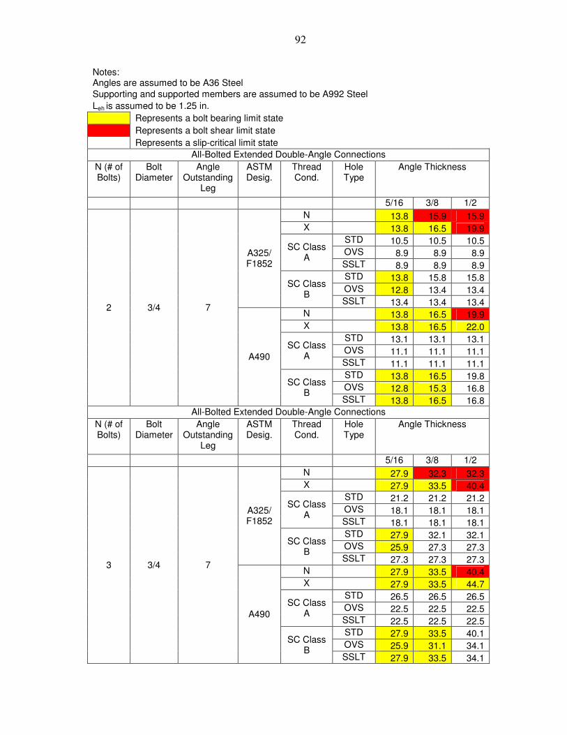
92
Notes: Angles are assumed to be A36 Steel
Supporting and supported members are assumed to be A992 Steel Leh is assumed to be 1.25 in. Represents a bolt bearing limit state Represents a bolt shear limit state Represents a slip-critical limit state All-Bolted Extended Double-Angle Connections
N (# of Bolts)
Bolt Diameter
Angle Outstanding
Leg
ASTM Desig.
Thread Cond.
Hole Type
Angle Thickness
5/16 3/8 1/2 N 13.8 15.9 15.9 X 13.8 16.5 19.9 STD 10.5 10.5 10.5 OVS 8.9 8.9 8.9
SC Class A
SSLT 8.9 8.9 8.9 STD 13.8 15.8 15.8 OVS 12.8 13.4 13.4
A325/ F1852
SC Class B
SSLT 13.4 13.4 13.4 N 13.8 16.5 19.9 X 13.8 16.5 22.0 STD 13.1 13.1 13.1 OVS 11.1 11.1 11.1
SC Class A
SSLT 11.1 11.1 11.1 STD 13.8 16.5 19.8 OVS 12.8 15.3 16.8
2 3/4 7
A490
SC Class B
SSLT 13.8 16.5 16.8 All-Bolted Extended Double-Angle Connections
N (# of Bolts)
Bolt Diameter
Angle Outstanding
Leg
ASTM Desig.
Thread Cond.
Hole Type
Angle Thickness
5/16 3/8 1/2 N 27.9 32.3 32.3 X 27.9 33.5 40.4 STD 21.2 21.2 21.2 OVS 18.1 18.1 18.1
SC Class A
SSLT 18.1 18.1 18.1 STD 27.9 32.1 32.1 OVS 25.9 27.3 27.3
A325/ F1852
SC Class B
SSLT 27.3 27.3 27.3 N 27.9 33.5 40.4 X 27.9 33.5 44.7 STD 26.5 26.5 26.5 OVS 22.5 22.5 22.5
SC Class A
SSLT 22.5 22.5 22.5 STD 27.9 33.5 40.1 OVS 25.9 31.1 34.1
3 3/4 7
A490
SC Class B
SSLT 27.9 33.5 34.1

93
Notes: Angles are assumed to be A36 Steel Supporting and supported members are assumed to be A992 Steel Leh is assumed to be 1.25 in. Represents a bolt bearing limit state Represents a bolt shear limit state Represents a slip-critical limit state All-Bolted Extended Double-Angle Connections
N (# of Bolts)
Bolt Diameter
Angle Outstanding
Leg
ASTM Desig.
Thread Cond.
Hole Type
Angle Thickness
5/16 3/8 1/2 N 50.1 58.0 58.0 X 50.1 60.1 72.5 STD 38.1 38.1 38.1 OVS 32.4 32.4 32.4
SC Class A
SSLT 32.4 32.4 32.4 STD 50.1 57.7 57.7 OVS 46.5 49.0 49.0
A325/ F1852
SC Class B
SSLT 49.0 49.0 49.0 N 50.1 60.1 72.5 X 50.1 60.1 80.2 STD 47.6 47.6 47.6 OVS 40.5 40.5 40.5
SC Class A
SSLT 40.5 40.5 40.5 STD 50.1 60.1 72.1 OVS 46.5 55.8 61.2
4 3/4 7
A490
SC Class B
SSLT 50.1 60.1 61.2 All-Bolted Extended Double-Angle Connections
N (# of Bolts)
Bolt Diameter
Angle Outstanding
Leg
ASTM Desig.
Thread Cond.
Hole Type
Angle Thickness
5/16 3/8 1/2 N 73.8 85.3 85.3 X 73.8 88.5 106.8 STD 56.1 56.1 56.1 OVS 47.7 47.7 47.7
SC Class A
SSLT 47.7 47.7 47.7 STD 73.8 84.9 84.9 OVS 68.4 72.1 72.1
A325/ F1852
SC Class B
SSLT 72.1 72.1 72.1 N 73.8 88.5 106.8 X 73.8 88.5 118.0 STD 70.0 70.0 70.0 OVS 59.6 59.6 59.6
SC Class A
SSLT 59.6 59.6 59.6 STD 73.8 88.5 106.1 OVS 68.4 82.1 90.1
5 3/4 7
A490
SC Class B
SSLT 73.8 88.5 90.1

94
Notes: Angles are assumed to be A36 Steel Supporting and supported members are assumed to be A992 Steel Leh is assumed to be 1.25 in. Represents a bolt bearing limit state Represents a bolt shear limit state Represents a slip-critical limit state All-Bolted Extended Double-Angle Connections
N (# of Bolts)
Bolt Diameter
Angle Outstanding
Leg
ASTM Desig.
Thread Cond.
Hole Type
Angle Thickness
5/16 3/8 1/2 N 100.6 116.3 116.3 X 100.6 120.7 145.6 STD 76.4 76.4 76.4 OVS 65.1 65.1 65.1
SC Class A
SSLT 65.1 65.1 65.1 STD 100.6 115.7 115.7 OVS 93.3 98.4 98.4
A325/ F1852
SC Class B
SSLT 98.4 98.4 98.4 N 100.6 120.7 145.6 X 100.6 120.7 160.9 STD 95.5 95.5 95.5 OVS 81.2 81.2 81.2
SC Class A
SSLT 81.2 81.2 81.2 STD 100.6 120.7 144.7 OVS 93.3 111.9 122.9
6 3/4 7
A490
SC Class B
SSLT 100.6 120.7 122.9 All-Bolted Extended Double-Angle Connections
N (# of Bolts)
Bolt Diameter
Angle Outstanding
Leg
ASTM Desig.
Thread Cond.
Hole Type
Angle Thickness
5/16 3/8 1/2 N 129.0 149.1 149.1 X 129.0 154.8 186.7 STD 98.0 98.0 98.0 OVS 83.5 83.5 83.5
SC Class A
SSLT 83.5 83.5 83.5 STD 129.0 148.4 148.4 OVS 119.6 126.1 126.1
A325/ F1852
SC Class B
SSLT 126.1 126.1 126.1 N 129.0 154.8 186.7 X 129.0 154.8 206.4 STD 122.4 122.4 122.4 OVS 104.1 104.1 104.1
SC Class A
SSLT 104.1 104.1 104.1 STD 129.0 154.8 185.5 OVS 119.6 143.5 157.6
7 3/4 7
A490
SC Class B
SSLT 129.0 154.8 157.6

95
Notes: Angles are assumed to be A36 Steel Supporting and supported members are assumed to be A992 Steel Leh is assumed to be 1.25 in. Represents a bolt bearing limit state Represents a bolt shear limit state Represents a slip-critical limit state All-Bolted Extended Double-Angle Connections
N (# of Bolts)
Bolt Diameter
Angle Outstanding
Leg
ASTM Desig.
Thread Cond.
Hole Type
Angle Thickness
5/16 3/8 1/2 N 158.3 183.0 183.0 X 158.3 189.9 229.0 STD 120.3 120.3 120.3 OVS 102.4 102.4 102.4
SC Class A
SSLT 102.4 102.4 102.4 STD 158.3 182.1 182.1 OVS 146.8 154.8 154.8
A325/ F1852
SC Class B
SSLT 154.8 154.8 154.8 N 158.3 189.9 229.0 X 158.3 189.9 253.2 STD 150.2 150.2 150.2 OVS 127.8 127.8 127.8
SC Class A
SSLT 127.8 127.8 127.8 STD 158.3 189.9 227.6 OVS 146.8 176.1 193.4
8 3/4 7
A490
SC Class B
SSLT 158.3 189.9 193.4 All-Bolted Extended Double-Angle Connections
N (# of Bolts)
Bolt Diameter
Angle Outstanding
Leg
ASTM Desig.
Thread Cond.
Hole Type
Angle Thickness
5/16 3/8 1/2 N 187.8 217.2 217.2 X 187.8 225.4 271.8 STD 142.7 142.7 142.7 OVS 121.6 121.6 121.6
SC Class A
SSLT 121.6 121.6 121.6 STD 187.8 216.1 216.1 OVS 174.2 183.7 183.7
A325/ F1852
SC Class B
SSLT 183.7 183.7 183.7 N 187.8 225.4 271.8 X 187.8 225.4 300.5 STD 178.3 178.3 178.3 OVS 151.6 151.6 151.6
SC Class A
SSLT 151.6 151.6 151.6 STD 187.8 225.4 270.1 OVS 174.2 209.0 229.5
9 3/4 7
A490
SC Class B
SSLT 187.8 225.4 229.5

96
Notes: Angles are assumed to be A36 Steel Supporting and supported members are assumed to be A992 Steel Leh is assumed to be 1.25 in. Represents a bolt bearing limit state Represents a bolt shear limit state Represents a slip-critical limit state All-Bolted Extended Double-Angle Connections
N (# of Bolts)
Bolt Diameter
Angle Outstanding
Leg
ASTM Desig.
Thread Cond.
Hole Type
Angle Thickness
5/16 3/8 1/2 N 217.7 251.8 251.8 X 217.7 261.3 315.1 STD 165.5 165.5 165.5 OVS 140.9 140.9 140.9
SC Class A
SSLT 140.9 140.9 140.9 STD 217.7 250.5 250.5 OVS 201.9 212.9 212.9
A325/ F1852
SC Class B
SSLT 212.9 212.9 212.9 N 217.7 261.3 315.1 X 217.7 261.3 348.4 STD 206.6 206.6 206.6 OVS 175.8 175.8 175.8
SC Class A
SSLT 175.8 175.8 175.8 STD 217.7 261.3 313.1 OVS 201.9 242.3 266.0
10 3/4 7
A490
SC Class B
SSLT 217.7 261.3 266.0 All-Bolted Extended Double-Angle Connections
N (# of Bolts)
Bolt Diameter
Angle Outstanding
Leg
ASTM Desig.
Thread Cond.
Hole Type
Angle Thickness
5/16 3/8 1/2 N 249.5 288.5 288.5 X 249.5 299.4 361.1 STD 189.6 189.6 189.6 OVS 161.5 161.5 161.5
SC Class A
SSLT 161.5 161.5 161.5 STD 249.5 287.1 287.1 OVS 231.3 244.0 244.0
A325/ F1852
SC Class B
SSLT 244.0 244.0 244.0 N 249.5 299.4 361.1 X 249.5 299.4 399.2 STD 236.8 236.8 236.8 OVS 201.4 201.4 201.4
SC Class A
SSLT 201.4 201.4 201.4 STD 249.5 299.4 358.8 OVS 231.3 277.6 304.8
11 3/4 7
A490
SC Class B
SSLT 249.5 299.4 304.8

97
Notes: Angles are assumed to be A36 Steel Supporting and supported members are assumed to be A992 Steel Leh is assumed to be 1.25 in. Represents a bolt bearing limit state Represents a bolt shear limit state Represents a slip-critical limit state All-Bolted Extended Double-Angle Connections
N (# of Bolts)
Bolt Diameter
Angle Outstanding
Leg
ASTM Desig.
Thread Cond.
Hole Type
Angle Thickness
5/16 3/8 1/2 N 276.9 320.2 320.2 X 276.9 332.3 400.8 STD 210.5 210.5 210.5 OVS 179.2 179.2 179.2
SC Class A
SSLT 179.2 179.2 179.2 STD 276.9 318.6 318.6 OVS 256.8 270.8 270.8
A325/ F1852
SC Class B
SSLT 270.8 270.8 270.8 N 276.9 332.3 400.8 X 276.9 332.3 443.1 STD 262.8 262.8 262.8 OVS 223.6 223.6 223.6
SC Class A
SSLT 223.6 223.6 223.6 STD 276.9 332.3 398.3 OVS 256.8 308.1 338.4
12 3/4 7
A490
SC Class B
SSLT 276.9 332.3 338.4

98
Notes: Angles are assumed to be A36 Steel Supporting and supported members are assumed to be A992 Steel Leh is assumed to be 1.25 in. Represents a bolt bearing limit state Represents a bolt shear limit state Represents a slip-critical limit state All-Bolted Extended Double-Angle Connections
N (# of Bolts)
Bolt Diameter
Angle Outstanding
Leg
ASTM Desig.
Thread Cond.
Hole Type
Angle Thickness
5/16 3/8 1/2 N 11.9 13.8 13.8 X 11.9 14.3 17.2 STD 9.1 9.1 9.1 OVS 7.7 7.7 7.7
SC Class A
SSLT 7.7 7.7 7.7 STD 11.9 13.7 13.7 OVS 11.0 11.6 11.6
A325/ F1852
SC Class B
SSLT 11.6 11.6 11.6 N 11.9 14.3 17.2 X 11.9 14.3 19.1 STD 11.3 11.3 11.3 OVS 9.6 9.6 9.6
SC Class A
SSLT 9.6 9.6 9.6 STD 11.9 14.3 17.1 OVS 11.0 13.3 14.6
2 3/4 8
A490
SC Class B
SSLT 11.9 14.3 14.6 All-Bolted Extended Double-Angle Connections
N (# of Bolts)
Bolt Diameter
Angle Outstanding
Leg
ASTM Desig.
Thread Cond.
Hole Type
Angle Thickness
5/16 3/8 1/2 N 24.1 27.9 27.9 X 24.1 28.9 34.9 STD 18.3 18.3 18.3 OVS 15.6 15.6 15.6
SC Class A
SSLT 15.6 15.6 15.6 STD 24.1 27.7 27.7 OVS 22.3 23.6 23.6
A325/ F1852
SC Class B
SSLT 23.6 23.6 23.6 N 24.1 28.9 34.9 X 24.1 28.9 38.6 STD 22.9 22.9 22.9 OVS 19.5 19.5 19.5
SC Class A
SSLT 19.5 19.5 19.5 STD 24.1 28.9 34.7 OVS 22.3 26.8 29.4
3 3/4 8
A490
SC Class B
SSLT 24.1 28.9 29.4

99
Notes: Angles are assumed to be A36 Steel Supporting and supported members are assumed to be A992 Steel Leh is assumed to be 1.25 in. Represents a bolt bearing limit state Represents a bolt shear limit state Represents a slip-critical limit state All-Bolted Extended Double-Angle Connections
N (# of Bolts)
Bolt Diameter
Angle Outstanding
Leg
ASTM Desig.
Thread Cond.
Hole Type
Angle Thickness
5/16 3/8 1/2 N 43.5 50.3 50.3 X 43.5 52.2 63.0 STD 33.1 33.1 33.1 OVS 28.2 28.2 28.2
SC Class A
SSLT 28.2 28.2 28.2 STD 43.5 50.1 50.1 OVS 40.4 42.6 42.6
A325/ F1852
SC Class B
SSLT 42.6 42.6 42.6 N 43.5 52.2 63.0 X 43.5 52.2 69.6 STD 41.3 41.3 41.3 OVS 35.1 35.1 35.1
SC Class A
SSLT 35.1 35.1 35.1 STD 43.5 52.2 62.6 OVS 40.4 48.4 53.2
4 3/4 8
A490
SC Class B
SSLT 43.5 52.2 53.2 All-Bolted Extended Double-Angle Connections
N (# of Bolts)
Bolt Diameter
Angle Outstanding
Leg
ASTM Desig.
Thread Cond.
Hole Type
Angle Thickness
5/16 3/8 1/2 N 65.5 75.8 75.8 X 65.5 78.6 94.8 STD 49.8 49.8 49.8 OVS 42.4 42.4 42.4
SC Class A
SSLT 42.4 42.4 42.4 STD 65.5 75.4 75.4 OVS 60.7 64.1 64.1
A325/ F1852
SC Class B
SSLT 64.1 64.1 64.1 N 65.5 78.6 94.8 X 65.5 78.6 104.8 STD 62.2 62.2 62.2 OVS 52.9 52.9 52.9
SC Class A
SSLT 52.9 52.9 52.9 STD 65.5 78.6 94.2 OVS 60.7 72.9 80.0
5 3/4 8
A490
SC Class B
SSLT 65.5 78.6 80.0

100
Notes: Angles are assumed to be A36 Steel Supporting and supported members are assumed to be A992 Steel Leh is assumed to be 1.25 in. Represents a bolt bearing limit state Represents a bolt shear limit state Represents a slip-critical limit state All-Bolted Extended Double-Angle Connections
N (# of Bolts)
Bolt Diameter
Angle Outstanding
Leg
ASTM Desig.
Thread Cond.
Hole Type
Angle Thickness
5/16 3/8 1/2 N 90.6 104.8 104.8 X 90.6 108.7 131.2 STD 68.9 68.9 68.9 OVS 58.7 58.7 58.7
SC Class A
SSLT 58.7 58.7 58.7 STD 90.6 104.3 104.3 OVS 84.0 88.6 88.6
A325/ F1852
SC Class B
SSLT 88.6 88.6 88.6 N 90.6 108.7 131.2 X 90.6 108.7 145.0 STD 86.0 86.0 86.0 OVS 73.2 73.2 73.2
SC Class A
SSLT 73.2 73.2 73.2 STD 90.6 108.7 130.3 OVS 84.0 100.8 110.7
6 3/4 8
A490
SC Class B
SSLT 90.6 108.7 110.7 All-Bolted Extended Double-Angle Connections
N (# of Bolts)
Bolt Diameter
Angle Outstanding
Leg
ASTM Desig.
Thread Cond.
Hole Type
Angle Thickness
5/16 3/8 1/2 N 117.6 136.0 136.0 X 117.6 141.1 170.2 STD 89.4 89.4 89.4 OVS 76.1 76.1 76.1
SC Class A
SSLT 76.1 76.1 76.1 STD 117.6 135.3 135.3 OVS 109.0 115.0 115.0
A325/ F1852
SC Class B
SSLT 115.0 115.0 115.0 N 117.6 141.1 170.2 X 117.6 141.1 188.1 STD 111.6 111.6 111.6 OVS 94.9 94.9 94.9
SC Class A
SSLT 94.9 94.9 94.9 STD 117.6 141.1 169.1 OVS 109.0 130.8 143.6
7 3/4 8
A490
SC Class B
SSLT 117.6 141.1 143.6

101
Notes: Angles are assumed to be A36 Steel Supporting and supported members are assumed to be A992 Steel Leh is assumed to be 1.25 in. Represents a bolt bearing limit state Represents a bolt shear limit state Represents a slip-critical limit state All-Bolted Extended Double-Angle Connections
N (# of Bolts)
Bolt Diameter
Angle Outstanding
Leg
ASTM Desig.
Thread Cond.
Hole Type
Angle Thickness
5/16 3/8 1/2 N 146.0 168.8 168.8 X 146.0 175.2 211.3 STD 110.9 110.9 110.9 OVS 94.5 94.5 94.5
SC Class A
SSLT 94.5 94.5 94.5 STD 146.0 168.0 168.0 OVS 135.4 142.8 142.8
A325/ F1852
SC Class B
SSLT 142.8 142.8 142.8 N 146.0 175.2 211.3 X 146.0 175.2 233.6 STD 138.5 138.5 138.5 OVS 117.8 117.8 117.8
SC Class A
SSLT 117.8 117.8 117.8 STD 146.0 175.2 209.9 OVS 135.4 162.4 178.4
8 3/4 8
A490
SC Class B
SSLT 146.0 175.2 178.4 All-Bolted Extended Double-Angle Connections
N (# of Bolts)
Bolt Diameter
Angle Outstanding
Leg
ASTM Desig.
Thread Cond.
Hole Type
Angle Thickness
5/16 3/8 1/2 N 175.0 202.4 202.4 X 175.0 210.0 253.3 STD 133.0 133.0 133.0 OVS 113.3 113.3 113.3
SC Class A
SSLT 113.3 113.3 113.3 STD 175.0 201.4 201.4 OVS 162.3 171.2 171.2
A325/ F1852
SC Class B
SSLT 171.2 171.2 171.2 N 175.0 210.0 253.3 X 175.0 210.0 280.1 STD 166.1 166.1 166.1 OVS 141.3 141.3 141.3
SC Class A
SSLT 141.3 141.3 141.3 STD 175.0 210.0 251.7 OVS 162.3 194.8 213.9
9 3/4 8
A490
SC Class B
SSLT 175.0 210.0 213.9

102
Notes: Angles are assumed to be A36 Steel Supporting and supported members are assumed to be A992 Steel Leh is assumed to be 1.25 in. Represents a bolt bearing limit state Represents a bolt shear limit state Represents a slip-critical limit state All-Bolted Extended Double-Angle Connections
N (# of Bolts)
Bolt Diameter
Angle Outstanding
Leg
ASTM Desig.
Thread Cond.
Hole Type
Angle Thickness
5/16 3/8 1/2 N 204.8 236.9 236.9 X 204.8 245.8 296.4 STD 155.7 155.7 155.7 OVS 132.6 132.6 132.6
SC Class A
SSLT 132.6 132.6 132.6 STD 204.8 235.7 235.7 OVS 189.9 200.3 200.3
A325/ F1852
SC Class B
SSLT 200.3 200.3 200.3 N 204.8 245.8 296.4 X 204.8 245.8 327.7 STD 194.4 194.4 194.4 OVS 165.4 165.4 165.4
SC Class A
SSLT 165.4 165.4 165.4 STD 204.8 245.8 294.6 OVS 189.9 227.9 250.3
10 3/4 8
A490
SC Class B
SSLT 204.8 245.8 250.3 All-Bolted Extended Double-Angle Connections
N (# of Bolts)
Bolt Diameter
Angle Outstanding
Leg
ASTM Desig.
Thread Cond.
Hole Type
Angle Thickness
5/16 3/8 1/2 N 234.5 271.2 271.2 X 234.5 281.4 339.4 STD 178.2 178.2 178.2 OVS 151.8 151.8 151.8
SC Class A
SSLT 151.8 151.8 151.8 STD 234.5 269.8 269.8 OVS 217.5 229.4 229.4
A325/ F1852
SC Class B
SSLT 229.4 229.4 229.4 N 234.5 281.4 339.4 X 234.5 281.4 375.2 STD 222.6 222.6 222.6 OVS 189.3 189.3 189.3
SC Class A
SSLT 189.3 189.3 189.3 STD 234.5 281.4 337.3 OVS 217.5 261.0 286.6
11 3/4 8
A490
SC Class B
SSLT 234.5 281.4 286.6

103
Notes: Angles are assumed to be A36 Steel Supporting and supported members are assumed to be A992 Steel Leh is assumed to be 1.25 in. Represents a bolt bearing limit state Represents a bolt shear limit state Represents a slip-critical limit state All-Bolted Extended Double-Angle Connections
N (# of Bolts)
Bolt Diameter
Angle Outstanding
Leg
ASTM Desig.
Thread Cond.
Hole Type
Angle Thickness
5/16 3/8 1/2 N 264.3 305.6 305.6 X 264.3 317.2 382.5 STD 200.9 200.9 200.9 OVS 171.1 171.1 171.1
SC Class A
SSLT 171.1 171.1 171.1 STD 264.3 304.1 304.1 OVS 245.1 258.5 258.5
A325/ F1852
SC Class B
SSLT 258.5 258.5 258.5 N 264.3 317.2 382.5 X 264.3 317.2 422.9 STD 250.9 250.9 250.9 OVS 213.4 213.4 213.4
SC Class A
SSLT 213.4 213.4 213.4 STD 264.3 317.2 380.1 OVS 245.1 294.1 322.9
12 3/4 8
A490
SC Class B
SSLT 264.3 317.2 322.9
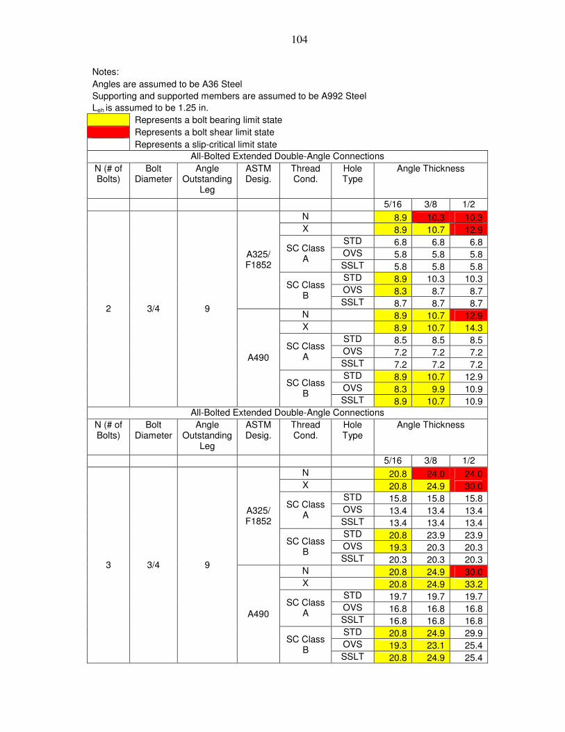
104
Notes: Angles are assumed to be A36 Steel Supporting and supported members are assumed to be A992 Steel Leh is assumed to be 1.25 in. Represents a bolt bearing limit state Represents a bolt shear limit state Represents a slip-critical limit state All-Bolted Extended Double-Angle Connections
N (# of Bolts)
Bolt Diameter
Angle Outstanding
Leg
ASTM Desig.
Thread Cond.
Hole Type
Angle Thickness
5/16 3/8 1/2 N 8.9 10.3 10.3 X 8.9 10.7 12.9 STD 6.8 6.8 6.8 OVS 5.8 5.8 5.8
SC Class A
SSLT 5.8 5.8 5.8 STD 8.9 10.3 10.3 OVS 8.3 8.7 8.7
A325/ F1852
SC Class B
SSLT 8.7 8.7 8.7 N 8.9 10.7 12.9 X 8.9 10.7 14.3 STD 8.5 8.5 8.5 OVS 7.2 7.2 7.2
SC Class A
SSLT 7.2 7.2 7.2 STD 8.9 10.7 12.9 OVS 8.3 9.9 10.9
2 3/4 9
A490
SC Class B
SSLT 8.9 10.7 10.9 All-Bolted Extended Double-Angle Connections
N (# of Bolts)
Bolt Diameter
Angle Outstanding
Leg
ASTM Desig.
Thread Cond.
Hole Type
Angle Thickness
5/16 3/8 1/2 N 20.8 24.0 24.0 X 20.8 24.9 30.0 STD 15.8 15.8 15.8 OVS 13.4 13.4 13.4
SC Class A
SSLT 13.4 13.4 13.4 STD 20.8 23.9 23.9 OVS 19.3 20.3 20.3
A325/ F1852
SC Class B
SSLT 20.3 20.3 20.3 N 20.8 24.9 30.0 X 20.8 24.9 33.2 STD 19.7 19.7 19.7 OVS 16.8 16.8 16.8
SC Class A
SSLT 16.8 16.8 16.8 STD 20.8 24.9 29.9 OVS 19.3 23.1 25.4
3 3/4 9
A490
SC Class B
SSLT 20.8 24.9 25.4

105
Notes: Angles are assumed to be A36 Steel Supporting and supported members are assumed to be A992 Steel Leh is assumed to be 1.25 in. Represents a bolt bearing limit state Represents a bolt shear limit state Represents a slip-critical limit state All-Bolted Extended Double-Angle Connections
N (# of Bolts)
Bolt Diameter
Angle Outstanding
Leg
ASTM Desig.
Thread Cond.
Hole Type
Angle Thickness
5/16 3/8 1/2 N 38.0 44.0 44.0 X 38.0 45.6 55.0 STD 28.9 28.9 28.9 OVS 24.6 24.6 24.6
SC Class A
SSLT 24.6 24.6 24.6 STD 38.0 43.7 43.7 OVS 35.3 37.2 37.2
A325/ F1852
SC Class B
SSLT 37.2 37.2 37.2 N 38.0 45.6 55.0 X 38.0 45.6 60.8 STD 36.1 36.1 36.1 OVS 30.7 30.7 30.7
SC Class A
SSLT 30.7 30.7 30.7 STD 38.0 45.6 54.7 OVS 35.3 42.3 46.5
4 3/4 9
A490
SC Class B
SSLT 38.0 45.6 46.5 All-Bolted Extended Double-Angle Connections
N (# of Bolts)
Bolt Diameter
Angle Outstanding
Leg
ASTM Desig.
Thread Cond.
Hole Type
Angle Thickness
5/16 3/8 1/2 N 57.8 66.8 66.8 X 57.8 69.3 83.6 STD 43.9 43.9 43.9 OVS 37.4 37.4 37.4
SC Class A
SSLT 37.4 37.4 37.4 STD 57.8 66.4 66.4 OVS 53.6 56.5 56.5
A325/ F1852
SC Class B
SSLT 56.5 56.5 56.5 N 57.8 69.3 83.6 X 57.8 69.3 92.4 STD 54.8 54.8 54.8 OVS 46.6 46.6 46.6
SC Class A
SSLT 46.6 46.6 46.6 STD 57.8 69.3 83.1 OVS 53.6 64.3 70.6
5 3/4 9
A490
SC Class B
SSLT 57.8 69.3 70.6

106
Notes: Angles are assumed to be A36 Steel Supporting and supported members are assumed to be A992 Steel Leh is assumed to be 1.25 in. Represents a bolt bearing limit state Represents a bolt shear limit state Represents a slip-critical limit state All-Bolted Extended Double-Angle Connections
N (# of Bolts)
Bolt Diameter
Angle Outstanding
Leg
ASTM Desig.
Thread Cond.
Hole Type
Angle Thickness
5/16 3/8 1/2 N 80.6 93.2 93.2 X 80.6 96.7 116.6 STD 61.2 61.2 61.2 OVS 52.2 52.2 52.2
SC Class A
SSLT 52.2 52.2 52.2 STD 80.6 92.7 92.7 OVS 74.7 78.8 78.8
A325/ F1852
SC Class B
SSLT 78.8 78.8 78.8 N 80.6 96.7 116.6 X 80.6 96.7 128.9 STD 76.5 76.5 76.5 OVS 65.0 65.0 65.0
SC Class A
SSLT 65.0 65.0 65.0 STD 80.6 96.7 115.9 OVS 74.7 89.7 98.4
6 3/4 9
A490
SC Class B
SSLT 80.6 96.7 98.4 All-Bolted Extended Double-Angle Connections
N (# of Bolts)
Bolt Diameter
Angle Outstanding
Leg
ASTM Desig.
Thread Cond.
Hole Type
Angle Thickness
5/16 3/8 1/2 N 105.7 122.3 122.3 X 105.7 126.9 153.0 STD 80.4 80.4 80.4 OVS 68.4 68.4 68.4
SC Class A
SSLT 68.4 68.4 68.4 STD 105.7 121.7 121.7 OVS 98.0 103.4 103.4
A325/ F1852
SC Class B
SSLT 103.4 103.4 103.4 N 105.7 126.9 153.0 X 105.7 126.9 169.2 STD 100.4 100.4 100.4 OVS 85.4 85.4 85.4
SC Class A
SSLT 85.4 85.4 85.4 STD 105.7 126.9 152.1 OVS 98.0 117.7 129.2
7 3/4 9
A490
SC Class B
SSLT 105.7 126.9 129.2

107
Notes: Angles are assumed to be A36 Steel Supporting and supported members are assumed to be A992 Steel Leh is assumed to be 1.25 in. Represents a bolt bearing limit state Represents a bolt shear limit state Represents a slip-critical limit state All-Bolted Extended Double-Angle Connections
N (# of Bolts)
Bolt Diameter
Angle Outstanding
Leg
ASTM Desig.
Thread Cond.
Hole Type
Angle Thickness
5/16 3/8 1/2 N 132.8 153.5 153.5 X 132.8 159.3 192.1 STD 100.9 100.9 100.9 OVS 85.9 85.9 85.9
SC Class A
SSLT 85.9 85.9 85.9 STD 132.8 152.7 152.7 OVS 123.1 129.8 129.8
A325/ F1852
SC Class B
SSLT 129.8 129.8 129.8 N 132.8 159.3 192.1 X 132.8 159.3 212.4 STD 126.0 126.0 126.0 OVS 107.2 107.2 107.2
SC Class A
SSLT 107.2 107.2 107.2 STD 132.8 159.3 190.9 OVS 123.1 147.7 162.2
8 3/4 9
A490
SC Class B
SSLT 132.8 159.3 162.2 All-Bolted Extended Double-Angle Connections
N (# of Bolts)
Bolt Diameter
Angle Outstanding
Leg
ASTM Desig.
Thread Cond.
Hole Type
Angle Thickness
5/16 3/8 1/2 N 160.8 186.0 186.0 X 160.8 193.0 232.7 STD 122.2 122.2 122.2 OVS 104.1 104.1 104.1
SC Class A
SSLT 104.1 104.1 104.1 STD 160.8 185.0 185.0 OVS 149.1 157.3 157.3
A325/ F1852
SC Class B
SSLT 157.3 157.3 157.3 N 160.8 193.0 232.7 X 160.8 193.0 257.3 STD 152.6 152.6 152.6 OVS 129.8 129.8 129.8
SC Class A
SSLT 129.8 129.8 129.8 STD 160.8 193.0 231.3 OVS 149.1 178.9 196.5
9 3/4 9
A490
SC Class B
SSLT 160.8 193.0 196.5

108
Notes: Angles are assumed to be A36 Steel Supporting and supported members are assumed to be A992 Steel Leh is assumed to be 1.25 in. Represents a bolt bearing limit state Represents a bolt shear limit state Represents a slip-critical limit state All-Bolted Extended Double-Angle Connections
N (# of Bolts)
Bolt Diameter
Angle Outstanding
Leg
ASTM Desig.
Thread Cond.
Hole Type
Angle Thickness
5/16 3/8 1/2 N 189.9 219.6 219.6 X 189.9 227.9 274.8 STD 144.3 144.3 144.3 OVS 122.9 122.9 122.9
SC Class A
SSLT 122.9 122.9 122.9 STD 189.9 218.5 218.5 OVS 176.1 185.7 185.7
A325/ F1852
SC Class B
SSLT 185.7 185.7 185.7 N 189.9 227.9 274.8 X 189.9 227.9 303.8 STD 180.2 180.2 180.2 OVS 153.3 153.3 153.3
SC Class A
SSLT 153.3 153.3 153.3 STD 189.9 227.9 273.1 OVS 176.1 211.3 232.0
10 3/4 9
A490
SC Class B
SSLT 189.9 227.9 232.0 All-Bolted Extended Double-Angle Connections
N (# of Bolts)
Bolt Diameter
Angle Outstanding
Leg
ASTM Desig.
Thread Cond.
Hole Type
Angle Thickness
5/16 3/8 1/2 N 219.4 253.7 253.7 X 219.4 263.3 317.5 STD 166.7 166.7 166.7 OVS 142.0 142.0 142.0
SC Class A
SSLT 142.0 142.0 142.0 STD 219.4 252.4 252.4 OVS 203.4 214.5 214.5
A325/ F1852
SC Class B
SSLT 214.5 214.5 214.5 N 219.4 263.3 317.5 X 219.4 263.3 351.0 STD 208.2 208.2 208.2 OVS 177.1 177.1 177.1
SC Class A
SSLT 177.1 177.1 177.1 STD 219.4 263.3 315.5 OVS 203.4 244.1 268.0
11 3/4 9
A490
SC Class B
SSLT 219.4 263.3 268.0

109
Notes: Angles are assumed to be A36 Steel Supporting and supported members are assumed to be A992 Steel Leh is assumed to be 1.25 in. Represents a bolt bearing limit state Represents a bolt shear limit state Represents a slip-critical limit state All-Bolted Extended Double-Angle Connections
N (# of Bolts)
Bolt Diameter
Angle Outstanding
Leg
ASTM Desig.
Thread Cond.
Hole Type
Angle Thickness
5/16 3/8 1/2 N 249.1 288.0 288.0 X 249.1 298.9 360.5 STD 189.3 189.3 189.3 OVS 161.2 161.2 161.2
SC Class A
SSLT 161.2 161.2 161.2 STD 249.1 286.6 286.6 OVS 231.0 243.6 243.6
A325/ F1852
SC Class B
SSLT 243.6 243.6 243.6 N 249.1 298.9 360.5 X 249.1 298.9 398.5 STD 236.4 236.4 236.4 OVS 201.1 201.1 201.1
SC Class A
SSLT 201.1 201.1 201.1 STD 249.1 298.9 358.2 OVS 231.0 277.2 304.3
12 3/4 9
A490
SC Class B
SSLT 249.1 298.9 304.3

110
APPENDIX B 7/8-INCH DIAMETER ALL-BOLTED A36 STEEL DOUBLE ANGLE
CONNECTIONS
The tables given in Appendix B are all-bolted double angle connections. The
angles are A36 angles using either A325/F1852 or A490 7/8-inch diameter bolts.

111
Notes: Angles are assumed to be A36 Steel Supporting and supported members are assumed to be A992 Steel Leh is assumed to be 1.25 in. Represents a bolt bearing limit state Represents a bolt shear limit state Represents a slip-critical limit state All-Bolted Extended Double-Angle Connections
N (# of Bolts)
Bolt Diameter
Angle Outstanding
Leg
ASTM Desig.
Thread Cond.
Hole Type
Angle Thickness
5/16 3/8 1/2 N 13.8 16.6 22.1 X 13.8 16.6 22.1 STD 13.8 15.8 15.8 OVS 12.7 13.4 13.4
SC Class A
SSLT 13.4 13.4 13.4 STD 13.8 16.6 22.1 OVS 12.7 15.3 20.3
A325/ F1852
SC Class B
SSLT 13.8 16.6 22.1 N 13.8 16.6 22.1 X 13.8 16.6 22.1 STD 13.8 16.6 19.8 OVS 12.7 15.3 16.9
SC Class A
SSLT 13.8 16.6 16.9 STD 13.8 16.6 22.1 OVS 12.7 15.3 20.3
2 7/8 6
A490
SC Class B
SSLT 13.8 16.6 22.1 All-Bolted Extended Double-Angle Connections
N (# of Bolts)
Bolt Diameter
Angle Outstanding
Leg
ASTM Desig.
Thread Cond.
Hole Type
Angle Thickness
5/16 3/8 1/2 N 30.9 37.1 49.5 X 30.9 37.1 49.5 STD 30.9 35.3 35.3 OVS 28.4 29.9 29.9
SC Class A
SSLT 29.9 29.9 29.9 STD 30.9 37.1 49.5 OVS 28.4 34.1 45.5
A325/ F1852
SC Class B
SSLT 30.9 37.1 49.5 N 30.9 37.1 49.5 X 30.9 37.1 49.5 STD 30.9 37.1 44.3 OVS 28.4 34.1 37.7
SC Class A
SSLT 30.9 37.1 37.7 STD 30.9 37.1 49.5 OVS 28.4 34.1 45.5
3 7/8 6
A490
SC Class B
SSLT 30.9 37.1 49.5

112
Notes: Angles are assumed to be A36 Steel Supporting and supported members are assumed to be A992 Steel Leh is assumed to be 1.25 in. Represents a bolt bearing limit state Represents a bolt shear limit state Represents a slip-critical limit state All-Bolted Extended Double-Angle Connections
N (# of Bolts)
Bolt Diameter
Angle Outstanding
Leg
ASTM Desig.
Thread Cond.
Hole Type
Angle Thickness
5/16 3/8 1/2 N 53.5 64.2 85.6 X 53.5 64.2 85.6 STD 53.5 61.0 61.0 OVS 49.2 51.8 51.8
SC Class A
SSLT 51.8 51.8 51.8 STD 53.5 64.2 85.6 OVS 49.2 59.0 78.7
A325/ F1852
SC Class B
SSLT 53.5 64.2 85.6 N 53.5 64.2 85.6 X 53.5 64.2 85.6 STD 53.5 64.2 76.6 OVS 49.2 59.0 65.2
SC Class A
SSLT 53.5 64.2 65.2 STD 53.5 64.2 85.6 OVS 49.2 59.0 78.7
4 7/8 6
A490
SC Class B
SSLT 53.5 64.2 85.6 All-Bolted Extended Double-Angle Connections
N (# of Bolts)
Bolt Diameter
Angle Outstanding
Leg
ASTM Desig.
Thread Cond.
Hole Type
Angle Thickness
5/16 3/8 1/2 N 78.3 93.9 125.3 X 78.3 93.9 125.3 STD 78.3 89.3 89.3 OVS 72.0 75.8 75.8
SC Class A
SSLT 75.8 75.8 75.8 STD 78.3 93.9 125.3 OVS 72.0 86.3 115.1
A325/ F1852
SC Class B
SSLT 78.3 93.9 125.3 N 78.3 93.9 125.3 X 78.3 93.9 125.3 STD 78.3 93.9 112.1 OVS 72.0 86.3 95.5
SC Class A
SSLT 78.3 93.9 95.5 STD 78.3 93.9 125.3 OVS 72.0 86.3 115.1
5 7/8 6
A490
SC Class B
SSLT 78.3 93.9 125.3

113
Notes: Angles are assumed to be A36 Steel Supporting and supported members are assumed to be A992 Steel Leh is assumed to be 1.25 in. Represents a bolt bearing limit state Represents a bolt shear limit state Represents a slip-critical limit state All-Bolted Extended Double-Angle Connections
N (# of Bolts)
Bolt Diameter
Angle Outstanding
Leg
ASTM Desig.
Thread Cond.
Hole Type
Angle Thickness
5/16 3/8 1/2 N 104.6 125.5 167.4 X 104.6 125.5 167.4 STD 104.6 119.4 119.4 OVS 96.2 101.3 101.3
SC Class A
SSLT 101.3 101.3 101.3 STD 104.6 125.5 167.4 OVS 96.2 115.4 153.8
A325/ F1852
SC Class B
SSLT 104.6 125.5 167.4 N 104.6 125.5 167.4 X 104.6 125.5 167.4 STD 104.6 125.5 149.7 OVS 96.2 115.4 127.6
SC Class A
SSLT 104.6 125.5 127.6 STD 104.6 125.5 167.4 OVS 96.2 115.4 153.8
6 7/8 6
A490
SC Class B
SSLT 104.6 125.5 167.4 All-Bolted Extended Double-Angle Connections
N (# of Bolts)
Bolt Diameter
Angle Outstanding
Leg
ASTM Desig.
Thread Cond.
Hole Type
Angle Thickness
5/16 3/8 1/2 N 132.2 158.7 211.5 X 132.2 158.7 211.5 STD 132.2 150.9 150.9 OVS 121.5 128.1 128.1
SC Class A
SSLT 128.1 128.1 128.1 STD 132.2 158.7 211.5 OVS 121.5 145.8 194.4
A325/ F1852
SC Class B
SSLT 132.2 158.7 211.5 N 132.2 158.7 211.5 X 132.2 158.7 211.5 STD 132.2 158.7 189.3 OVS 121.5 145.8 161.3
SC Class A
SSLT 132.2 158.7 161.3 STD 132.2 158.7 211.5 OVS 121.5 145.8 194.4
7 7/8 6
A490
SC Class B
SSLT 132.2 158.7 211.5
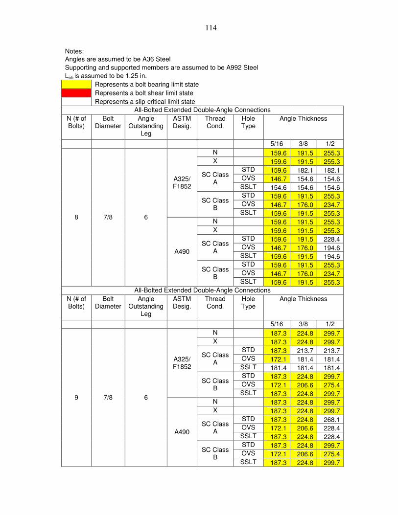
114
Notes: Angles are assumed to be A36 Steel Supporting and supported members are assumed to be A992 Steel Leh is assumed to be 1.25 in. Represents a bolt bearing limit state Represents a bolt shear limit state Represents a slip-critical limit state All-Bolted Extended Double-Angle Connections
N (# of Bolts)
Bolt Diameter
Angle Outstanding
Leg
ASTM Desig.
Thread Cond.
Hole Type
Angle Thickness
5/16 3/8 1/2 N 159.6 191.5 255.3 X 159.6 191.5 255.3 STD 159.6 182.1 182.1 OVS 146.7 154.6 154.6
SC Class A
SSLT 154.6 154.6 154.6 STD 159.6 191.5 255.3 OVS 146.7 176.0 234.7
A325/ F1852
SC Class B
SSLT 159.6 191.5 255.3 N 159.6 191.5 255.3 X 159.6 191.5 255.3 STD 159.6 191.5 228.4 OVS 146.7 176.0 194.6
SC Class A
SSLT 159.6 191.5 194.6 STD 159.6 191.5 255.3 OVS 146.7 176.0 234.7
8 7/8 6
A490
SC Class B
SSLT 159.6 191.5 255.3 All-Bolted Extended Double-Angle Connections
N (# of Bolts)
Bolt Diameter
Angle Outstanding
Leg
ASTM Desig.
Thread Cond.
Hole Type
Angle Thickness
5/16 3/8 1/2 N 187.3 224.8 299.7 X 187.3 224.8 299.7 STD 187.3 213.7 213.7 OVS 172.1 181.4 181.4
SC Class A
SSLT 181.4 181.4 181.4 STD 187.3 224.8 299.7 OVS 172.1 206.6 275.4
A325/ F1852
SC Class B
SSLT 187.3 224.8 299.7 N 187.3 224.8 299.7 X 187.3 224.8 299.7 STD 187.3 224.8 268.1 OVS 172.1 206.6 228.4
SC Class A
SSLT 187.3 224.8 228.4 STD 187.3 224.8 299.7 OVS 172.1 206.6 275.4
9 7/8 6
A490
SC Class B
SSLT 187.3 224.8 299.7

115
Notes: Angles are assumed to be A36 Steel Supporting and supported members are assumed to be A992 Steel Leh is assumed to be 1.25 in. Represents a bolt bearing limit state Represents a bolt shear limit state Represents a slip-critical limit state All-Bolted Extended Double-Angle Connections
N (# of Bolts)
Bolt Diameter
Angle Outstanding
Leg
ASTM Desig.
Thread Cond.
Hole Type
Angle Thickness
5/16 3/8 1/2 N 214.7 257.7 343.5 X 214.7 257.7 343.5 STD 214.7 245.0 245.0 OVS 197.3 208.0 208.0
SC Class A
SSLT 208.0 208.0 208.0 STD 214.7 257.7 343.5 OVS 197.3 236.8 315.8
A325/ F1852
SC Class B
SSLT 214.7 257.7 343.5 N 214.7 257.7 343.5 X 214.7 257.7 343.5 STD 214.7 257.7 307.3 OVS 197.3 236.8 261.9
SC Class A
SSLT 214.7 257.7 261.9 STD 214.7 257.7 343.5 OVS 197.3 236.8 315.8
10 7/8 6
A490
SC Class B
SSLT 214.7 257.7 343.5 All-Bolted Extended Double-Angle Connections
N (# of Bolts)
Bolt Diameter
Angle Outstanding
Leg
ASTM Desig.
Thread Cond.
Hole Type
Angle Thickness
5/16 3/8 1/2 N 242.1 290.5 387.4 X 242.1 290.5 387.4 STD 242.1 276.3 276.3 OVS 222.5 234.5 234.5
SC Class A
SSLT 234.5 234.5 234.5 STD 242.1 290.5 387.4 OVS 222.5 267.0 356.1
A325/ F1852
SC Class B
SSLT 242.1 290.5 387.4 N 242.1 290.5 387.4 X 242.1 290.5 387.4 STD 242.1 290.5 346.6 OVS 222.5 267.0 295.3
SC Class A
SSLT 242.1 290.5 295.3 STD 242.1 290.5 387.4 OVS 222.5 267.0 356.1
11 7/8 6
A490
SC Class B
SSLT 242.1 290.5 387.4

116
Notes: Angles are assumed to be A36 Steel Supporting and supported members are assumed to be A992 Steel Leh is assumed to be 1.25 in. Represents a bolt bearing limit state Represents a bolt shear limit state Represents a slip-critical limit state All-Bolted Extended Double-Angle Connections
N (# of Bolts)
Bolt Diameter
Angle Outstanding
Leg
ASTM Desig.
Thread Cond.
Hole Type
Angle Thickness
5/16 3/8 1/2 N 268.4 322.1 429.4 X 268.4 322.1 429.4 STD 268.4 306.3 306.3 OVS 246.7 260.0 260.0
SC Class A
SSLT 260.0 260.0 260.0 STD 268.4 322.1 429.4 OVS 246.7 296.0 394.7
A325/ F1852
SC Class B
SSLT 268.4 322.1 429.4 N 268.4 322.1 429.4 X 268.4 322.1 429.4 STD 268.4 322.1 384.2 OVS 246.7 296.0 327.3
SC Class A
SSLT 268.4 322.1 327.3 STD 268.4 322.1 429.4 OVS 246.7 296.0 394.7
12 7/8 6
A490
SC Class B
SSLT 268.4 322.1 429.4
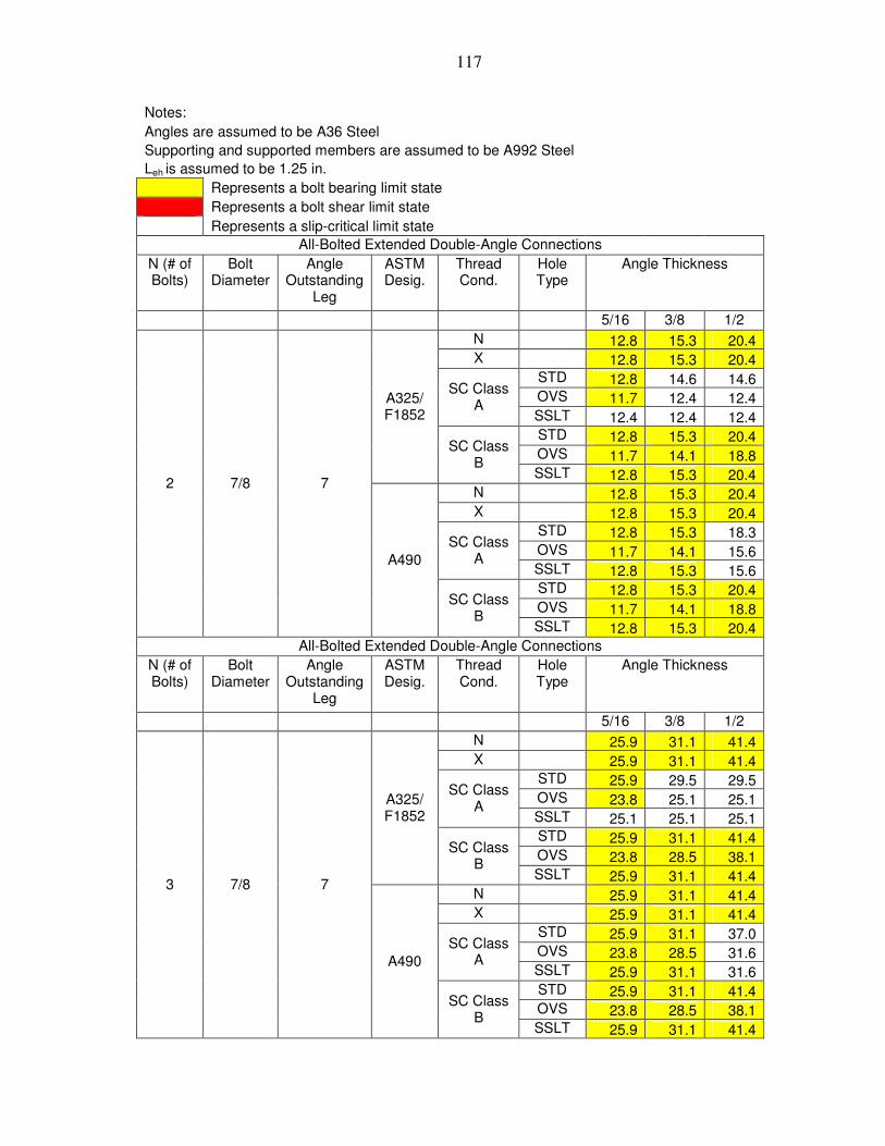
117
Notes: Angles are assumed to be A36 Steel Supporting and supported members are assumed to be A992 Steel Leh is assumed to be 1.25 in. Represents a bolt bearing limit state Represents a bolt shear limit state Represents a slip-critical limit state All-Bolted Extended Double-Angle Connections
N (# of Bolts)
Bolt Diameter
Angle Outstanding
Leg
ASTM Desig.
Thread Cond.
Hole Type
Angle Thickness
5/16 3/8 1/2 N 12.8 15.3 20.4 X 12.8 15.3 20.4 STD 12.8 14.6 14.6 OVS 11.7 12.4 12.4
SC Class A
SSLT 12.4 12.4 12.4 STD 12.8 15.3 20.4 OVS 11.7 14.1 18.8
A325/ F1852
SC Class B
SSLT 12.8 15.3 20.4 N 12.8 15.3 20.4 X 12.8 15.3 20.4 STD 12.8 15.3 18.3 OVS 11.7 14.1 15.6
SC Class A
SSLT 12.8 15.3 15.6 STD 12.8 15.3 20.4 OVS 11.7 14.1 18.8
2 7/8 7
A490
SC Class B
SSLT 12.8 15.3 20.4 All-Bolted Extended Double-Angle Connections
N (# of Bolts)
Bolt Diameter
Angle Outstanding
Leg
ASTM Desig.
Thread Cond.
Hole Type
Angle Thickness
5/16 3/8 1/2 N 25.9 31.1 41.4 X 25.9 31.1 41.4 STD 25.9 29.5 29.5 OVS 23.8 25.1 25.1
SC Class A
SSLT 25.1 25.1 25.1 STD 25.9 31.1 41.4 OVS 23.8 28.5 38.1
A325/ F1852
SC Class B
SSLT 25.9 31.1 41.4 N 25.9 31.1 41.4 X 25.9 31.1 41.4 STD 25.9 31.1 37.0 OVS 23.8 28.5 31.6
SC Class A
SSLT 25.9 31.1 31.6 STD 25.9 31.1 41.4 OVS 23.8 28.5 38.1
3 7/8 7
A490
SC Class B
SSLT 25.9 31.1 41.4

118
Notes: Angles are assumed to be A36 Steel Supporting and supported members are assumed to be A992 Steel Leh is assumed to be 1.25 in. Represents a bolt bearing limit state Represents a bolt shear limit state Represents a slip-critical limit state All-Bolted Extended Double-Angle Connections
N (# of Bolts)
Bolt Diameter
Angle Outstanding
Leg
ASTM Desig.
Thread Cond.
Hole Type
Angle Thickness
5/16 3/8 1/2 N 46.5 55.8 74.4 X 46.5 55.8 74.4 STD 46.5 53.0 53.0 OVS 42.7 45.0 45.0
SC Class A
SSLT 45.0 45.0 45.0 STD 46.5 55.8 74.4 OVS 42.7 51.3 68.3
A325/ F1852
SC Class B
SSLT 46.5 55.8 74.4 N 46.5 55.8 74.4 X 46.5 55.8 74.4 STD 46.5 55.8 66.5 OVS 42.7 51.3 56.7
SC Class A
SSLT 46.5 55.8 56.7 STD 46.5 55.8 74.4 OVS 42.7 51.3 68.3
4 7/8 7
A490
SC Class B
SSLT 46.5 55.8 74.4 All-Bolted Extended Double-Angle Connections
N (# of Bolts)
Bolt Diameter
Angle Outstanding
Leg
ASTM Desig.
Thread Cond.
Hole Type
Angle Thickness
5/16 3/8 1/2 N 68.4 82.1 109.4 X 68.4 82.1 109.4 STD 68.4 78.1 78.1 OVS 62.9 66.3 66.3
SC Class A
SSLT 66.3 66.3 66.3 STD 68.4 82.1 109.4 OVS 62.9 75.4 100.6
A325/ F1852
SC Class B
SSLT 68.4 82.1 109.4 N 68.4 82.1 109.4 X 68.4 82.1 109.4 STD 68.4 82.1 97.9 OVS 62.9 75.4 83.4
SC Class A
SSLT 68.4 82.1 83.4 STD 68.4 82.1 109.4 OVS 62.9 75.4 100.6
5 7/8 7
A490
SC Class B
SSLT 68.4 82.1 109.4

119
Notes: Angles are assumed to be A36 Steel Supporting and supported members are assumed to be A992 Steel Leh is assumed to be 1.25 in. Represents a bolt bearing limit state Represents a bolt shear limit state Represents a slip-critical limit state All-Bolted Extended Double-Angle Connections
N (# of Bolts)
Bolt Diameter
Angle Outstanding
Leg
ASTM Desig.
Thread Cond.
Hole Type
Angle Thickness
5/16 3/8 1/2 N 93.3 111.9 149.2 X 93.3 111.9 149.2 STD 93.3 106.4 106.4 OVS 85.7 90.3 90.3
SC Class A
SSLT 90.3 90.3 90.3 STD 93.3 111.9 149.2 OVS 85.7 102.9 137.2
A325/ F1852
SC Class B
SSLT 93.3 111.9 149.2 N 93.3 111.9 149.2 X 93.3 111.9 149.2 STD 93.3 111.9 133.5 OVS 85.7 102.9 113.7
SC Class A
SSLT 93.3 111.9 113.7 STD 93.3 111.9 149.2 OVS 85.7 102.9 137.2
6 7/8 7
A490
SC Class B
SSLT 93.3 111.9 149.2 All-Bolted Extended Double-Angle Connections
N (# of Bolts)
Bolt Diameter
Angle Outstanding
Leg
ASTM Desig.
Thread Cond.
Hole Type
Angle Thickness
5/16 3/8 1/2 N 119.6 143.5 191.4 X 119.6 143.5 191.4 STD 119.6 136.5 136.5 OVS 109.9 115.8 115.8
SC Class A
SSLT 115.8 115.8 115.8 STD 119.6 143.5 191.4 OVS 109.9 131.9 175.9
A325/ F1852
SC Class B
SSLT 119.6 143.5 191.4 N 119.6 143.5 191.4 X 119.6 143.5 191.4 STD 119.6 143.5 171.2 OVS 109.9 131.9 145.9
SC Class A
SSLT 119.6 143.5 145.9 STD 119.6 143.5 191.4 OVS 109.9 131.9 175.9
7 7/8 7
A490
SC Class B
SSLT 119.6 143.5 191.4

120
Notes: Angles are assumed to be A36 Steel Supporting and supported members are assumed to be A992 Steel Leh is assumed to be 1.25 in. Represents a bolt bearing limit state Represents a bolt shear limit state Represents a slip-critical limit state All-Bolted Extended Double-Angle Connections
N (# of Bolts)
Bolt Diameter
Angle Outstanding
Leg
ASTM Desig.
Thread Cond.
Hole Type
Angle Thickness
5/16 3/8 1/2 N 146.8 176.1 234.8 X 146.8 176.1 234.8 STD 146.8 167.5 167.5 OVS 134.9 142.1 142.1
SC Class A
SSLT 142.1 142.1 142.1 STD 146.8 176.1 234.8 OVS 134.9 161.9 215.8
A325/ F1852
SC Class B
SSLT 146.8 176.1 234.8 N 146.8 176.1 234.8 X 146.8 176.1 234.8 STD 146.8 176.1 210.1 OVS 134.9 161.9 179.0
SC Class A
SSLT 146.8 176.1 179.0 STD 146.8 176.1 234.8 OVS 134.9 161.9 215.8
8 7/8 7
A490
SC Class B
SSLT 146.8 176.1 234.8 All-Bolted Extended Double-Angle Connections
N (# of Bolts)
Bolt Diameter
Angle Outstanding
Leg
ASTM Desig.
Thread Cond.
Hole Type
Angle Thickness
5/16 3/8 1/2 N 174.2 209.0 278.7 X 174.2 209.0 278.7 STD 174.2 198.8 198.8 OVS 160.1 168.7 168.7
SC Class A
SSLT 168.7 168.7 168.7 STD 174.2 209.0 278.7 OVS 160.1 192.1 256.1
A325/ F1852
SC Class B
SSLT 174.2 209.0 278.7 N 174.2 209.0 278.7 X 174.2 209.0 278.7 STD 174.2 209.0 249.3 OVS 160.1 192.1 212.4
SC Class A
SSLT 174.2 209.0 212.4 STD 174.2 209.0 278.7 OVS 160.1 192.1 256.1
9 7/8 7
A490
SC Class B
SSLT 174.2 209.0 278.7

121
Notes: Angles are assumed to be A36 Steel Supporting and supported members are assumed to be A992 Steel Leh is assumed to be 1.25 in. Represents a bolt bearing limit state Represents a bolt shear limit state Represents a slip-critical limit state All-Bolted Extended Double-Angle Connections
N (# of Bolts)
Bolt Diameter
Angle Outstanding
Leg
ASTM Desig.
Thread Cond.
Hole Type
Angle Thickness
5/16 3/8 1/2 N 201.9 242.3 323.0 X 201.9 242.3 323.0 STD 201.9 230.4 230.4 OVS 185.6 195.6 195.6
SC Class A
SSLT 195.6 195.6 195.6 STD 201.9 242.3 323.0 OVS 185.6 222.7 296.9
A325/ F1852
SC Class B
SSLT 201.9 242.3 323.0 N 201.9 242.3 323.0 X 201.9 242.3 323.0 STD 201.9 242.3 289.0 OVS 185.6 222.7 246.2
SC Class A
SSLT 201.9 242.3 246.2 STD 201.9 242.3 323.0 OVS 185.6 222.7 296.9
10 7/8 7
A490
SC Class B
SSLT 201.9 242.3 323.0 All-Bolted Extended Double-Angle Connections
N (# of Bolts)
Bolt Diameter
Angle Outstanding
Leg
ASTM Desig.
Thread Cond.
Hole Type
Angle Thickness
5/16 3/8 1/2 N 231.3 277.6 370.2 X 231.3 277.6 370.2 STD 231.3 264.0 264.0 OVS 212.6 224.1 224.1
SC Class A
SSLT 224.1 224.1 224.1 STD 231.3 277.6 370.2 OVS 212.6 255.2 340.2
A325/ F1852
SC Class B
SSLT 231.3 277.6 370.2 N 231.3 277.6 370.2 X 231.3 277.6 370.2 STD 231.3 277.6 331.1 OVS 212.6 255.2 282.2
SC Class A
SSLT 231.3 277.6 282.2 STD 231.3 277.6 370.2 OVS 212.6 255.2 340.2
11 7/8 7
A490
SC Class B
SSLT 231.3 277.6 370.2

122
Notes: Angles are assumed to be A36 Steel Supporting and supported members are assumed to be A992 Steel Leh is assumed to be 1.25 in. Represents a bolt bearing limit state Represents a bolt shear limit state Represents a slip-critical limit state All-Bolted Extended Double-Angle Connections
N (# of Bolts)
Bolt Diameter
Angle Outstanding
Leg
ASTM Desig.
Thread Cond.
Hole Type
Angle Thickness
5/16 3/8 1/2 N 256.8 308.1 410.9 X 256.8 308.1 410.9 STD 256.8 293.0 293.0 OVS 236.0 248.7 248.7
SC Class A
SSLT 248.7 248.7 248.7 STD 256.8 308.1 410.9 OVS 236.0 283.2 377.6
A325/ F1852
SC Class B
SSLT 256.8 308.1 410.9 N 256.8 308.1 410.9 X 256.8 308.1 410.9 STD 256.8 308.1 367.6 OVS 236.0 283.2 313.2
SC Class A
SSLT 256.8 308.1 313.2 STD 256.8 308.1 410.9 OVS 236.0 283.2 377.6
12 7/8 7
A490
SC Class B
SSLT 256.8 308.1 410.9

123
Notes: Angles are assumed to be A36 Steel Supporting and supported members are assumed to be A992 Steel Leh is assumed to be 1.25 in. Represents a bolt bearing limit state Represents a bolt shear limit state Represents a slip-critical limit state All-Bolted Extended Double-Angle Connections
N (# of Bolts)
Bolt Diameter
Angle Outstanding
Leg
ASTM Desig.
Thread Cond.
Hole Type
Angle Thickness
5/16 3/8 1/2 N 11.0 13.3 17.7 X 11.0 13.3 17.7 STD 11.0 12.6 12.6 OVS 10.2 10.7 10.7
SC Class A
SSLT 10.7 10.7 10.7 STD 11.0 13.3 17.7 OVS 10.2 12.2 16.2
A325/ F1852
SC Class B
SSLT 11.0 13.3 17.7 N 11.0 13.3 17.7 X 11.0 13.3 17.7 STD 11.0 13.3 15.8 OVS 10.2 12.2 13.5
SC Class A
SSLT 11.0 13.3 13.5 STD 11.0 13.3 17.7 OVS 10.2 12.2 16.2
2 7/8 8
A490
SC Class B
SSLT 11.0 13.3 17.7 All-Bolted Extended Double-Angle Connections
N (# of Bolts)
Bolt Diameter
Angle Outstanding
Leg
ASTM Desig.
Thread Cond.
Hole Type
Angle Thickness
5/16 3/8 1/2 N 22.3 26.8 35.7 X 22.3 26.8 35.7 STD 22.3 25.5 25.5 OVS 20.5 21.6 21.6
SC Class A
SSLT 21.6 21.6 21.6 STD 22.3 26.8 35.7 OVS 20.5 24.6 32.9
A325/ F1852
SC Class B
SSLT 22.3 26.8 35.7 N 22.3 26.8 35.7 X 22.3 26.8 35.7 STD 22.3 26.8 32.0 OVS 20.5 24.6 27.2
SC Class A
SSLT 22.3 26.8 27.2 STD 22.3 26.8 35.7 OVS 20.5 24.6 32.9
3 7/8 8
A490
SC Class B
SSLT 22.3 26.8 35.7

124
Notes: Angles are assumed to be A36 Steel Supporting and supported members are assumed to be A992 Steel Leh is assumed to be 1.25 in. Represents a bolt bearing limit state Represents a bolt shear limit state Represents a slip-critical limit state All-Bolted Extended Double-Angle Connections
N (# of Bolts)
Bolt Diameter
Angle Outstanding
Leg
ASTM Desig.
Thread Cond.
Hole Type
Angle Thickness
5/16 3/8 1/2 N 40.4 48.4 64.6 X 40.4 48.4 64.6 STD 40.4 46.1 46.1 OVS 37.1 39.1 39.1
SC Class A
SSLT 39.1 39.1 39.1 STD 40.4 48.4 64.6 OVS 37.1 44.5 59.3
A325/ F1852
SC Class B
SSLT 40.4 48.4 64.6 N 40.4 48.4 64.6 X 40.4 48.4 64.6 STD 40.4 48.4 57.8 OVS 37.1 44.5 49.2
SC Class A
SSLT 40.4 48.4 49.2 STD 40.4 48.4 64.6 OVS 37.1 44.5 59.3
4 7/8 8
A490
SC Class B
SSLT 40.4 48.4 64.6 All-Bolted Extended Double-Angle Connections
N (# of Bolts)
Bolt Diameter
Angle Outstanding
Leg
ASTM Desig.
Thread Cond.
Hole Type
Angle Thickness
5/16 3/8 1/2 N 60.7 72.9 97.2 X 60.7 72.9 97.2 STD 60.7 69.3 69.3 OVS 55.8 58.8 58.8
SC Class A
SSLT 58.8 58.8 58.8 STD 60.7 72.9 97.2 OVS 55.8 67.0 89.3
A325/ F1852
SC Class B
SSLT 60.7 72.9 97.2 N 60.7 72.9 97.2 X 60.7 72.9 97.2 STD 60.7 72.9 87.0 OVS 55.8 67.0 74.1
SC Class A
SSLT 60.7 72.9 74.1 STD 60.7 72.9 97.2 OVS 55.8 67.0 89.3
5 7/8 8
A490
SC Class B
SSLT 60.7 72.9 97.2

125
Notes: Angles are assumed to be A36 Steel Supporting and supported members are assumed to be A992 Steel Leh is assumed to be 1.25 in. Represents a bolt bearing limit state Represents a bolt shear limit state Represents a slip-critical limit state All-Bolted Extended Double-Angle Connections
N (# of Bolts)
Bolt Diameter
Angle Outstanding
Leg
ASTM Desig.
Thread Cond.
Hole Type
Angle Thickness
5/16 3/8 1/2 N 84.0 100.8 134.5 X 84.0 100.8 134.5 STD 84.0 95.9 95.9 OVS 77.2 81.4 81.4
SC Class A
SSLT 81.4 81.4 81.4 STD 84.0 100.8 134.5 OVS 77.2 92.7 123.6
A325/ F1852
SC Class B
SSLT 84.0 100.8 134.5 N 84.0 100.8 134.5 X 84.0 100.8 134.5 STD 84.0 100.8 120.3 OVS 77.2 92.7 102.5
SC Class A
SSLT 84.0 100.8 102.5 STD 84.0 100.8 134.5 OVS 77.2 92.7 123.6
6 7/8 8
A490
SC Class B
SSLT 84.0 100.8 134.5 All-Bolted Extended Double-Angle Connections
N (# of Bolts)
Bolt Diameter
Angle Outstanding
Leg
ASTM Desig.
Thread Cond.
Hole Type
Angle Thickness
5/16 3/8 1/2 N 109.0 130.8 174.4 X 109.0 130.8 174.4 STD 109.0 124.4 124.4 OVS 100.2 105.6 105.6
SC Class A
SSLT 105.6 105.6 105.6 STD 109.0 130.8 174.4 OVS 100.2 120.2 160.3
A325/ F1852
SC Class B
SSLT 109.0 130.8 174.4 N 109.0 130.8 174.4 X 109.0 130.8 174.4 STD 109.0 130.8 156.0 OVS 100.2 120.2 133.0
SC Class A
SSLT 109.0 130.8 133.0 STD 109.0 130.8 174.4 OVS 100.2 120.2 160.3
7 7/8 8
A490
SC Class B
SSLT 109.0 130.8 174.4

126
Notes: Angles are assumed to be A36 Steel Supporting and supported members are assumed to be A992 Steel Leh is assumed to be 1.25 in. Represents a bolt bearing limit state Represents a bolt shear limit state Represents a slip-critical limit state All-Bolted Extended Double-Angle Connections
N (# of Bolts)
Bolt Diameter
Angle Outstanding
Leg
ASTM Desig.
Thread Cond.
Hole Type
Angle Thickness
5/16 3/8 1/2 N 135.4 162.4 216.6 X 135.4 162.4 216.6 STD 135.4 154.5 154.5 OVS 124.4 131.1 131.1
SC Class A
SSLT 131.1 131.1 131.1 STD 135.4 162.4 216.6 OVS 124.4 149.3 199.1
A325/ F1852
SC Class B
SSLT 135.4 162.4 216.6 N 135.4 162.4 216.6 X 135.4 162.4 216.6 STD 135.4 162.4 193.8 OVS 124.4 149.3 165.1
SC Class A
SSLT 135.4 162.4 165.1 STD 135.4 162.4 216.6 OVS 124.4 149.3 199.1
8 7/8 8
A490
SC Class B
SSLT 135.4 162.4 216.6 All-Bolted Extended Double-Angle Connections
N (# of Bolts)
Bolt Diameter
Angle Outstanding
Leg
ASTM Desig.
Thread Cond.
Hole Type
Angle Thickness
5/16 3/8 1/2 N 162.3 194.8 259.7 X 162.3 194.8 259.7 STD 162.3 185.2 185.2 OVS 149.2 157.2 157.2
SC Class A
SSLT 157.2 157.2 157.2 STD 162.3 194.8 259.7 OVS 149.2 179.0 238.7
A325/ F1852
SC Class B
SSLT 162.3 194.8 259.7 N 162.3 194.8 259.7 X 162.3 194.8 259.7 STD 162.3 194.8 232.3 OVS 149.2 179.0 198.0
SC Class A
SSLT 162.3 194.8 198.0 STD 162.3 194.8 259.7 OVS 149.2 179.0 238.7
9 7/8 8
A490
SC Class B
SSLT 162.3 194.8 259.7

127
Notes: Angles are assumed to be A36 Steel Supporting and supported members are assumed to be A992 Steel Leh is assumed to be 1.25 in. Represents a bolt bearing limit state Represents a bolt shear limit state Represents a slip-critical limit state All-Bolted Extended Double-Angle Connections
N (# of Bolts)
Bolt Diameter
Angle Outstanding
Leg
ASTM Desig.
Thread Cond.
Hole Type
Angle Thickness
5/16 3/8 1/2 N 189.9 227.9 303.9 X 189.9 227.9 303.9 STD 189.9 216.7 216.7 OVS 174.6 184.0 184.0
SC Class A
SSLT 184.0 184.0 184.0 STD 189.9 227.9 303.9 OVS 174.6 209.5 279.3
A325/ F1852
SC Class B
SSLT 189.9 227.9 303.9 N 189.9 227.9 303.9 X 189.9 227.9 303.9 STD 189.9 227.9 271.9 OVS 174.6 209.5 231.6
SC Class A
SSLT 189.9 227.9 231.6 STD 189.9 227.9 303.9 OVS 174.6 209.5 279.3
10 7/8 8
A490
SC Class B
SSLT 189.9 227.9 303.9 All-Bolted Extended Double-Angle Connections
N (# of Bolts)
Bolt Diameter
Angle Outstanding
Leg
ASTM Desig.
Thread Cond.
Hole Type
Angle Thickness
5/16 3/8 1/2 N 217.5 261.0 348.0 X 217.5 261.0 348.0 STD 217.5 248.2 248.2 OVS 199.9 210.6 210.6
SC Class A
SSLT 210.6 210.6 210.6 STD 217.5 261.0 348.0 OVS 199.9 239.9 319.8
A325/ F1852
SC Class B
SSLT 217.5 261.0 348.0 N 217.5 261.0 348.0 X 217.5 261.0 348.0 STD 217.5 261.0 311.3 OVS 199.9 239.9 265.2
SC Class A
SSLT 217.5 261.0 265.2 STD 217.5 261.0 348.0 OVS 199.9 239.9 319.8
11 7/8 8
A490
SC Class B
SSLT 217.5 261.0 348.0

128
Notes: Angles are assumed to be A36 Steel Supporting and supported members are assumed to be A992 Steel Leh is assumed to be 1.25 in. Represents a bolt bearing limit state Represents a bolt shear limit state Represents a slip-critical limit state All-Bolted Extended Double-Angle Connections
N (# of Bolts)
Bolt Diameter
Angle Outstanding
Leg
ASTM Desig.
Thread Cond.
Hole Type
Angle Thickness
5/16 3/8 1/2 N 245.1 294.1 392.2 X 245.1 294.1 392.2 STD 245.1 279.7 279.7 OVS 225.3 237.4 237.4
SC Class A
SSLT 237.4 237.4 237.4 STD 245.1 294.1 392.2 OVS 225.3 270.3 360.4
A325/ F1852
SC Class B
SSLT 245.1 294.1 392.2 N 245.1 294.1 392.2 X 245.1 294.1 392.2 STD 245.1 294.1 350.8 OVS 225.3 270.3 298.9
SC Class A
SSLT 245.1 294.1 298.9 STD 245.1 294.1 392.2 OVS 225.3 270.3 360.4
12 7/8 8
A490
SC Class B
SSLT 245.1 294.1 392.2

129
Notes: Angles are assumed to be A36 Steel Supporting and supported members are assumed to be A992 Steel Leh is assumed to be 1.25 in. Represents a bolt bearing limit state Represents a bolt shear limit state Represents a slip-critical limit state All-Bolted Extended Double-Angle Connections
N (# of Bolts)
Bolt Diameter
Angle Outstanding
Leg
ASTM Desig.
Thread Cond.
Hole Type
Angle Thickness
5/16 3/8 1/2 N 8.3 9.9 13.3 X 8.3 9.9 13.3 STD 8.3 9.5 9.5 OVS 7.6 8.0 8.0
SC Class A
SSLT 8.0 8.0 8.0 STD 8.3 9.9 13.3 OVS 7.6 9.1 12.2
A325/ F1852
SC Class B
SSLT 8.3 9.9 13.3 N 8.3 9.9 13.3 X 8.3 9.9 13.3 STD 8.3 9.9 11.9 OVS 7.6 9.1 10.1
SC Class A
SSLT 8.3 9.9 10.1 STD 8.3 9.9 13.3 OVS 7.6 9.1 12.2
2 7/8 9
A490
SC Class B
SSLT 8.3 9.9 13.3 All-Bolted Extended Double-Angle Connections
N (# of Bolts)
Bolt Diameter
Angle Outstanding
Leg
ASTM Desig.
Thread Cond.
Hole Type
Angle Thickness
5/16 3/8 1/2 N 19.3 23.1 30.8 X 19.3 23.1 30.8 STD 19.3 22.0 22.0 OVS 17.7 18.6 18.6
SC Class A
SSLT 18.6 18.6 18.6 STD 19.3 23.1 30.8 OVS 17.7 21.2 28.3
A325/ F1852
SC Class B
SSLT 19.3 23.1 30.8 N 19.3 23.1 30.8 X 19.3 23.1 30.8 STD 19.3 23.1 27.6 OVS 17.7 21.2 23.5
SC Class A
SSLT 19.3 23.1 23.5 STD 19.3 23.1 30.8 OVS 17.7 21.2 28.3
3 7/8 9
A490
SC Class B
SSLT 19.3 23.1 30.8

130
Notes: Angles are assumed to be A36 Steel Supporting and supported members are assumed to be A992 Steel Leh is assumed to be 1.25 in. Represents a bolt bearing limit state Represents a bolt shear limit state Represents a slip-critical limit state All-Bolted Extended Double-Angle Connections
N (# of Bolts)
Bolt Diameter
Angle Outstanding
Leg
ASTM Desig.
Thread Cond.
Hole Type
Angle Thickness
5/16 3/8 1/2 N 35.3 42.3 56.4 X 35.3 42.3 56.4 STD 35.3 40.2 40.2 OVS 32.4 34.1 34.1
SC Class A
SSLT 34.1 34.1 34.1 STD 35.3 42.3 56.4 OVS 32.4 38.9 51.8
A325/ F1852
SC Class B
SSLT 35.3 42.3 56.4 N 35.3 42.3 56.4 X 35.3 42.3 56.4 STD 35.3 42.3 50.5 OVS 32.4 38.9 43.0
SC Class A
SSLT 35.3 42.3 43.0 STD 35.3 42.3 56.4 OVS 32.4 38.9 51.8
4 7/8 9
A490
SC Class B
SSLT 35.3 42.3 56.4 All-Bolted Extended Double-Angle Connections
N (# of Bolts)
Bolt Diameter
Angle Outstanding
Leg
ASTM Desig.
Thread Cond.
Hole Type
Angle Thickness
5/16 3/8 1/2 N 53.6 64.3 85.7 X 53.6 64.3 85.7 STD 53.6 61.1 61.1 OVS 49.2 51.9 51.9
SC Class A
SSLT 51.9 51.9 51.9 STD 53.6 64.3 85.7 OVS 49.2 59.1 78.8
A325/ F1852
SC Class B
SSLT 53.6 64.3 85.7 N 53.6 64.3 85.7 X 53.6 64.3 85.7 STD 53.6 64.3 76.7 OVS 49.2 59.1 65.3
SC Class A
SSLT 53.6 64.3 65.3 STD 53.6 64.3 85.7 OVS 49.2 59.1 78.8
5 7/8 9
A490
SC Class B
SSLT 53.6 64.3 85.7

131
Notes: Angles are assumed to be A36 Steel Supporting and supported members are assumed to be A992 Steel Leh is assumed to be 1.25 in. Represents a bolt bearing limit state Represents a bolt shear limit state Represents a slip-critical limit state All-Bolted Extended Double-Angle Connections
N (# of Bolts)
Bolt Diameter
Angle Outstanding
Leg
ASTM Desig.
Thread Cond.
Hole Type
Angle Thickness
5/16 3/8 1/2 N 74.7 89.7 119.5 X 74.7 89.7 119.5 STD 74.7 85.3 85.3 OVS 68.7 72.4 72.4
SC Class A
SSLT 72.4 72.4 72.4 STD 74.7 89.7 119.5 OVS 68.7 82.4 109.9
A325/ F1852
SC Class B
SSLT 74.7 89.7 119.5 N 74.7 89.7 119.5 X 74.7 89.7 119.5 STD 74.7 89.7 106.9 OVS 68.7 82.4 91.1
SC Class A
SSLT 74.7 89.7 91.1 STD 74.7 89.7 119.5 OVS 68.7 82.4 109.9
6 7/8 9
A490
SC Class B
SSLT 74.7 89.7 119.5 All-Bolted Extended Double-Angle Connections
N (# of Bolts)
Bolt Diameter
Angle Outstanding
Leg
ASTM Desig.
Thread Cond.
Hole Type
Angle Thickness
5/16 3/8 1/2 N 98.0 117.7 156.9 X 98.0 117.7 156.9 STD 98.0 111.9 111.9 OVS 90.1 95.0 95.0
SC Class A
SSLT 95.0 95.0 95.0 STD 98.0 117.7 156.9 OVS 90.1 108.1 144.2
A325/ F1852
SC Class B
SSLT 98.0 117.7 156.9 N 98.0 117.7 156.9 X 98.0 117.7 156.9 STD 98.0 117.7 140.3 OVS 90.1 108.1 119.6
SC Class A
SSLT 98.0 117.7 119.6 STD 98.0 117.7 156.9 OVS 90.1 108.1 144.2
7 7/8 9
A490
SC Class B
SSLT 98.0 117.7 156.9

132
Notes: Angles are assumed to be A36 Steel Supporting and supported members are assumed to be A992 Steel Leh is assumed to be 1.25 in. Represents a bolt bearing limit state Represents a bolt shear limit state Represents a slip-critical limit state All-Bolted Extended Double-Angle Connections
N (# of Bolts)
Bolt Diameter
Angle Outstanding
Leg
ASTM Desig.
Thread Cond.
Hole Type
Angle Thickness
5/16 3/8 1/2 N 123.1 147.7 197.0 X 123.1 147.7 197.0 STD 123.1 140.5 140.5 OVS 113.1 119.2 119.2
SC Class A
SSLT 119.2 119.2 119.2 STD 123.1 147.7 197.0 OVS 113.1 135.8 181.0
A325/ F1852
SC Class B
SSLT 123.1 147.7 197.0 N 123.1 147.7 197.0 X 123.1 147.7 197.0 STD 123.1 147.7 176.2 OVS 113.1 135.8 150.1
SC Class A
SSLT 123.1 147.7 150.1 STD 123.1 147.7 197.0 OVS 113.1 135.8 181.0
8 7/8 9
A490
SC Class B
SSLT 123.1 147.7 197.0 All-Bolted Extended Double-Angle Connections
N (# of Bolts)
Bolt Diameter
Angle Outstanding
Leg
ASTM Desig.
Thread Cond.
Hole Type
Angle Thickness
5/16 3/8 1/2 N 149.1 178.9 238.6 X 149.1 178.9 238.6 STD 149.1 170.2 170.2 OVS 137.1 144.4 144.4
SC Class A
SSLT 144.4 144.4 144.4 STD 149.1 178.9 238.6 OVS 137.1 164.5 219.3
A325/ F1852
SC Class B
SSLT 149.1 178.9 238.6 N 149.1 178.9 238.6 X 149.1 178.9 238.6 STD 149.1 178.9 213.4 OVS 137.1 164.5 181.9
SC Class A
SSLT 149.1 178.9 181.9 STD 149.1 178.9 238.6 OVS 137.1 164.5 219.3
9 7/8 9
A490
SC Class B
SSLT 149.1 178.9 238.6

133
Notes: Angles are assumed to be A36 Steel Supporting and supported members are assumed to be A992 Steel Leh is assumed to be 1.25 in. Represents a bolt bearing limit state Represents a bolt shear limit state Represents a slip-critical limit state All-Bolted Extended Double-Angle Connections
N (# of Bolts)
Bolt Diameter
Angle Outstanding
Leg
ASTM Desig.
Thread Cond.
Hole Type
Angle Thickness
5/16 3/8 1/2 N 176.1 211.3 281.7 X 176.1 211.3 281.7 STD 176.1 200.9 200.9 OVS 161.8 170.6 170.6
SC Class A
SSLT 170.6 170.6 170.6 STD 176.1 211.3 281.7 OVS 161.8 194.2 258.9
A325/ F1852
SC Class B
SSLT 176.1 211.3 281.7 N 176.1 211.3 281.7 X 176.1 211.3 281.7 STD 176.1 211.3 252.0 OVS 161.8 194.2 214.7
SC Class A
SSLT 176.1 211.3 214.7 STD 176.1 211.3 281.7 OVS 161.8 194.2 258.9
10 7/8 9
A490
SC Class B
SSLT 176.1 211.3 281.7 All-Bolted Extended Double-Angle Connections
N (# of Bolts)
Bolt Diameter
Angle Outstanding
Leg
ASTM Desig.
Thread Cond.
Hole Type
Angle Thickness
5/16 3/8 1/2 N 203.4 244.1 325.5 X 203.4 244.1 325.5 STD 203.4 232.1 232.1 OVS 187.0 197.0 197.0
SC Class A
SSLT 197.0 197.0 197.0 STD 203.4 244.1 325.5 OVS 187.0 224.4 299.2
A325/ F1852
SC Class B
SSLT 203.4 244.1 325.5 N 203.4 244.1 325.5 X 203.4 244.1 325.5 STD 203.4 244.1 291.2 OVS 187.0 224.4 248.1
SC Class A
SSLT 203.4 244.1 248.1 STD 203.4 244.1 325.5 OVS 187.0 224.4 299.2
11 7/8 9
A490
SC Class B
SSLT 203.4 244.1 325.5

134
Notes: Angles are assumed to be A36 Steel Supporting and supported members are assumed to be A992 Steel Leh is assumed to be 1.25 in. Represents a bolt bearing limit state Represents a bolt shear limit state Represents a slip-critical limit state All-Bolted Extended Double-Angle Connections
N (# of Bolts)
Bolt Diameter
Angle Outstanding
Leg
ASTM Desig.
Thread Cond.
Hole Type
Angle Thickness
5/16 3/8 1/2 N 231.0 277.2 369.5 X 231.0 277.2 369.5 STD 231.0 263.6 263.6 OVS 212.3 223.7 223.7
SC Class A
SSLT 223.7 223.7 223.7 STD 231.0 277.2 369.5 OVS 212.3 254.7 339.7
A325/ F1852
SC Class B
SSLT 231.0 277.2 369.5 N 231.0 277.2 369.5 X 231.0 277.2 369.5 STD 231.0 277.2 330.6 OVS 212.3 254.7 281.7
SC Class A
SSLT 231.0 277.2 281.7 STD 231.0 277.2 369.5 OVS 212.3 254.7 339.7
12 7/8 9
A490
SC Class B
SSLT 231.0 277.2 369.5

135
APPENDIX C 1-INCH DIAMETER ALL-BOLTED A36 STEEL DOUBLE ANGLE
CONNECTIONS
The tables given in Appendix C are all-bolted double angle connections. The
angles are A36 angles using either A325/F1852 or A490 1-inch diameter bolts.
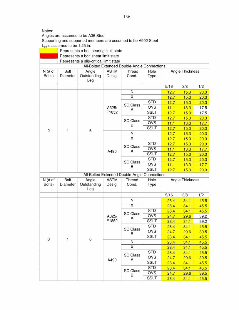
136
Notes: Angles are assumed to be A36 Steel Supporting and supported members are assumed to be A992 Steel Leh is assumed to be 1.25 in. Represents a bolt bearing limit state Represents a bolt shear limit state Represents a slip-critical limit state All-Bolted Extended Double-Angle Connections
N (# of Bolts)
Bolt Diameter
Angle Outstanding
Leg
ASTM Desig.
Thread Cond.
Hole Type
Angle Thickness
5/16 3/8 1/2 N 12.7 15.3 20.3 X 12.7 15.3 20.3 STD 12.7 15.3 20.3 OVS 11.1 13.3 17.5
SC Class A
SSLT 12.7 15.3 17.5 STD 12.7 15.3 20.3 OVS 11.1 13.3 17.7
A325/ F1852
SC Class B
SSLT 12.7 15.3 20.3 N 12.7 15.3 20.3 X 12.7 15.3 20.3 STD 12.7 15.3 20.3 OVS 11.1 13.3 17.7
SC Class A
SSLT 12.7 15.3 20.3 STD 12.7 15.3 20.3 OVS 11.1 13.3 17.7
2 1 6
A490
SC Class B
SSLT 12.7 15.3 20.3 All-Bolted Extended Double-Angle Connections
N (# of Bolts)
Bolt Diameter
Angle Outstanding
Leg
ASTM Desig.
Thread Cond.
Hole Type
Angle Thickness
5/16 3/8 1/2 N 28.4 34.1 45.5 X 28.4 34.1 45.5 STD 28.4 34.1 45.5 OVS 24.7 29.6 39.2
SC Class A
SSLT 28.4 34.1 39.2 STD 28.4 34.1 45.5 OVS 24.7 29.6 39.5
A325/ F1852
SC Class B
SSLT 28.4 34.1 45.5 N 28.4 34.1 45.5 X 28.4 34.1 45.5 STD 28.4 34.1 45.5 OVS 24.7 29.6 39.5
SC Class A
SSLT 28.4 34.1 45.5 STD 28.4 34.1 45.5 OVS 24.7 29.6 39.5
3 1 6
A490
SC Class B
SSLT 28.4 34.1 45.5

137
Notes: Angles are assumed to be A36 Steel Supporting and supported members are assumed to be A992 Steel Leh is assumed to be 1.25 in. Represents a bolt bearing limit state Represents a bolt shear limit state Represents a slip-critical limit state All-Bolted Extended Double-Angle Connections
N (# of Bolts)
Bolt Diameter
Angle Outstanding
Leg
ASTM Desig.
Thread Cond.
Hole Type
Angle Thickness
5/16 3/8 1/2 N 49.2 59.0 78.7 X 49.2 59.0 78.7 STD 49.2 59.0 78.7 OVS 42.7 51.3 67.7
SC Class A
SSLT 49.2 59.0 67.7 STD 49.2 59.0 78.7 OVS 42.7 51.3 68.4
A325/ F1852
SC Class B
SSLT 49.2 59.0 78.7 N 49.2 59.0 78.7 X 49.2 59.0 78.7 STD 49.2 59.0 78.7 OVS 42.7 51.3 68.4
SC Class A
SSLT 49.2 59.0 78.7 STD 49.2 59.0 78.7 OVS 42.7 51.3 68.4
4 1 6
A490
SC Class B
SSLT 49.2 59.0 78.7 All-Bolted Extended Double-Angle Connections
N (# of Bolts)
Bolt Diameter
Angle Outstanding
Leg
ASTM Desig.
Thread Cond.
Hole Type
Angle Thickness
5/16 3/8 1/2 N 72.0 86.3 115.1 X 72.0 86.3 115.1 STD 72.0 86.3 115.1 OVS 62.6 75.1 99.2
SC Class A
SSLT 72.0 86.3 99.2 STD 72.0 86.3 115.1 OVS 62.6 75.1 100.1
A325/ F1852
SC Class B
SSLT 72.0 86.3 115.1 N 72.0 86.3 115.1 X 72.0 86.3 115.1 STD 72.0 86.3 115.1 OVS 62.6 75.1 100.1
SC Class A
SSLT 72.0 86.3 115.1 STD 72.0 86.3 115.1 OVS 62.6 75.1 100.1
5 1 6
A490
SC Class B
SSLT 72.0 86.3 115.1
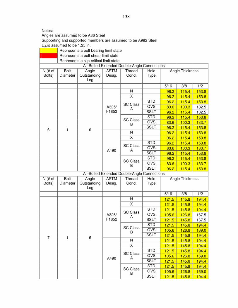
138
Notes: Angles are assumed to be A36 Steel Supporting and supported members are assumed to be A992 Steel Leh is assumed to be 1.25 in. Represents a bolt bearing limit state Represents a bolt shear limit state Represents a slip-critical limit state All-Bolted Extended Double-Angle Connections
N (# of Bolts)
Bolt Diameter
Angle Outstanding
Leg
ASTM Desig.
Thread Cond.
Hole Type
Angle Thickness
5/16 3/8 1/2 N 96.2 115.4 153.8 X 96.2 115.4 153.8 STD 96.2 115.4 153.8 OVS 83.6 100.3 132.5
SC Class A
SSLT 96.2 115.4 132.5 STD 96.2 115.4 153.8 OVS 83.6 100.3 133.7
A325/ F1852
SC Class B
SSLT 96.2 115.4 153.8 N 96.2 115.4 153.8 X 96.2 115.4 153.8 STD 96.2 115.4 153.8 OVS 83.6 100.3 133.7
SC Class A
SSLT 96.2 115.4 153.8 STD 96.2 115.4 153.8 OVS 83.6 100.3 133.7
6 1 6
A490
SC Class B
SSLT 96.2 115.4 153.8 All-Bolted Extended Double-Angle Connections
N (# of Bolts)
Bolt Diameter
Angle Outstanding
Leg
ASTM Desig.
Thread Cond.
Hole Type
Angle Thickness
5/16 3/8 1/2 N 121.5 145.8 194.4 X 121.5 145.8 194.4 STD 121.5 145.8 194.4 OVS 105.6 126.8 167.5
SC Class A
SSLT 121.5 145.8 167.5 STD 121.5 145.8 194.4 OVS 105.6 126.8 169.0
A325/ F1852
SC Class B
SSLT 121.5 145.8 194.4 N 121.5 145.8 194.4 X 121.5 145.8 194.4 STD 121.5 145.8 194.4 OVS 105.6 126.8 169.0
SC Class A
SSLT 121.5 145.8 194.4 STD 121.5 145.8 194.4 OVS 105.6 126.8 169.0
7 1 6
A490
SC Class B
SSLT 121.5 145.8 194.4

139
Notes: Angles are assumed to be A36 Steel Supporting and supported members are assumed to be A992 Steel Leh is assumed to be 1.25 in. Represents a bolt bearing limit state Represents a bolt shear limit state Represents a slip-critical limit state All-Bolted Extended Double-Angle Connections
N (# of Bolts)
Bolt Diameter
Angle Outstanding
Leg
ASTM Desig.
Thread Cond.
Hole Type
Angle Thickness
5/16 3/8 1/2 N 146.7 176.0 234.7 X 146.7 176.0 234.7 STD 146.7 176.0 234.7 OVS 127.5 153.0 202.1
SC Class A
SSLT 146.7 176.0 202.1 STD 146.7 176.0 234.7 OVS 127.5 153.0 204.0
A325/ F1852
SC Class B
SSLT 146.7 176.0 234.7 N 146.7 176.0 234.7 X 146.7 176.0 234.7 STD 146.7 176.0 234.7 OVS 127.5 153.0 204.0
SC Class A
SSLT 146.7 176.0 234.7 STD 146.7 176.0 234.7 OVS 127.5 153.0 204.0
8 1 6
A490
SC Class B
SSLT 146.7 176.0 234.7 All-Bolted Extended Double-Angle Connections
N (# of Bolts)
Bolt Diameter
Angle Outstanding
Leg
ASTM Desig.
Thread Cond.
Hole Type
Angle Thickness
5/16 3/8 1/2 N 172.1 206.6 275.4 X 172.1 206.6 275.4 STD 172.1 206.6 275.4 OVS 149.7 179.6 237.2
SC Class A
SSLT 172.1 206.6 237.2 STD 172.1 206.6 275.4 OVS 149.7 179.6 239.4
A325/ F1852
SC Class B
SSLT 172.1 206.6 275.4 N 172.1 206.6 275.4 X 172.1 206.6 275.4 STD 172.1 206.6 275.4 OVS 149.7 179.6 239.4
SC Class A
SSLT 172.1 206.6 275.4 STD 172.1 206.6 275.4 OVS 149.7 179.6 239.4
9 1 6
A490
SC Class B
SSLT 172.1 206.6 275.4

140
Notes: Angles are assumed to be A36 Steel Supporting and supported members are assumed to be A992 Steel Leh is assumed to be 1.25 in. Represents a bolt bearing limit state Represents a bolt shear limit state Represents a slip-critical limit state All-Bolted Extended Double-Angle Connections
N (# of Bolts)
Bolt Diameter
Angle Outstanding
Leg
ASTM Desig.
Thread Cond.
Hole Type
Angle Thickness
5/16 3/8 1/2 N 197.3 236.8 315.8 X 197.3 236.8 315.8 STD 197.3 236.8 315.8 OVS 171.6 205.9 272.0
SC Class A
SSLT 197.3 236.8 272.0 STD 197.3 236.8 315.8 OVS 171.6 205.9 274.5
A325/ F1852
SC Class B
SSLT 197.3 236.8 315.8 N 197.3 236.8 315.8 X 197.3 236.8 315.8 STD 197.3 236.8 315.8 OVS 171.6 205.9 274.5
SC Class A
SSLT 197.3 236.8 315.8 STD 197.3 236.8 315.8 OVS 171.6 205.9 274.5
10 1 6
A490
SC Class B
SSLT 197.3 236.8 315.8 All-Bolted Extended Double-Angle Connections
N (# of Bolts)
Bolt Diameter
Angle Outstanding
Leg
ASTM Desig.
Thread Cond.
Hole Type
Angle Thickness
5/16 3/8 1/2 N 222.5 267.0 356.1 X 222.5 267.0 356.1 STD 222.5 267.0 356.1 OVS 193.5 232.2 306.7
SC Class A
SSLT 222.5 267.0 306.7 STD 222.5 267.0 356.1 OVS 193.5 232.2 309.5
A325/ F1852
SC Class B
SSLT 222.5 267.0 356.1 N 222.5 267.0 356.1 X 222.5 267.0 356.1 STD 222.5 267.0 356.1 OVS 193.5 232.2 309.5
SC Class A
SSLT 222.5 267.0 356.1 STD 222.5 267.0 356.1 OVS 193.5 232.2 309.5
11 1 6
A490
SC Class B
SSLT 222.5 267.0 356.1
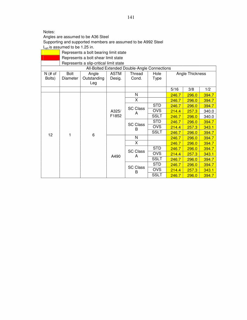
141
Notes: Angles are assumed to be A36 Steel Supporting and supported members are assumed to be A992 Steel Leh is assumed to be 1.25 in. Represents a bolt bearing limit state Represents a bolt shear limit state Represents a slip-critical limit state All-Bolted Extended Double-Angle Connections
N (# of Bolts)
Bolt Diameter
Angle Outstanding
Leg
ASTM Desig.
Thread Cond.
Hole Type
Angle Thickness
5/16 3/8 1/2 N 246.7 296.0 394.7 X 246.7 296.0 394.7 STD 246.7 296.0 394.7 OVS 214.4 257.3 340.0
SC Class A
SSLT 246.7 296.0 340.0 STD 246.7 296.0 394.7 OVS 214.4 257.3 343.1
A325/ F1852
SC Class B
SSLT 246.7 296.0 394.7 N 246.7 296.0 394.7 X 246.7 296.0 394.7 STD 246.7 296.0 394.7 OVS 214.4 257.3 343.1
SC Class A
SSLT 246.7 296.0 394.7 STD 246.7 296.0 394.7 OVS 214.4 257.3 343.1
12 1 6
A490
SC Class B
SSLT 246.7 296.0 394.7

142
Notes: Angles are assumed to be A36 Steel Supporting and supported members are assumed to be A992 Steel Leh is assumed to be 1.25 in. Represents a bolt bearing limit state Represents a bolt shear limit state Represents a slip-critical limit state All-Bolted Extended Double-Angle Connections
N (# of Bolts)
Bolt Diameter
Angle Outstanding
Leg
ASTM Desig.
Thread Cond.
Hole Type
Angle Thickness
5/16 3/8 1/2 N 11.7 14.1 18.8 X 11.7 14.1 18.8 STD 11.7 14.1 18.8 OVS 10.2 12.2 16.2
SC Class A
SSLT 11.7 14.1 16.2 STD 11.7 14.1 18.8 OVS 10.2 12.2 16.3
A325/ F1852
SC Class B
SSLT 11.7 14.1 18.8 N 11.7 14.1 18.8 X 11.7 14.1 18.8 STD 11.7 14.1 18.8 OVS 10.2 12.2 16.3
SC Class A
SSLT 11.7 14.1 18.8 STD 11.7 14.1 18.8 OVS 10.2 12.2 16.3
2 1 7
A490
SC Class B
SSLT 11.7 14.1 18.8 All-Bolted Extended Double-Angle Connections
N (# of Bolts)
Bolt Diameter
Angle Outstanding
Leg
ASTM Desig.
Thread Cond.
Hole Type
Angle Thickness
5/16 3/8 1/2 N 23.8 28.5 38.1 X 23.8 28.5 38.1 STD 23.8 28.5 38.1 OVS 20.7 24.8 32.8
SC Class A
SSLT 23.8 28.5 32.8 STD 23.8 28.5 38.1 OVS 20.7 24.8 33.1
A325/ F1852
SC Class B
SSLT 23.8 28.5 38.1 N 23.8 28.5 38.1 X 23.8 28.5 38.1 STD 23.8 28.5 38.1 OVS 20.7 24.8 33.1
SC Class A
SSLT 23.8 28.5 38.1 STD 23.8 28.5 38.1 OVS 20.7 24.8 33.1
3 1 7
A490
SC Class B
SSLT 23.8 28.5 38.1

143
Notes: Angles are assumed to be A36 Steel Supporting and supported members are assumed to be A992 Steel Leh is assumed to be 1.25 in. Represents a bolt bearing limit state Represents a bolt shear limit state Represents a slip-critical limit state All-Bolted Extended Double-Angle Connections
N (# of Bolts)
Bolt Diameter
Angle Outstanding
Leg
ASTM Desig.
Thread Cond.
Hole Type
Angle Thickness
5/16 3/8 1/2 N 42.7 51.3 68.3 X 42.7 51.3 68.3 STD 42.7 51.3 68.3 OVS 37.1 44.6 58.9
SC Class A
SSLT 42.7 51.3 58.9 STD 42.7 51.3 68.3 OVS 37.1 44.6 59.4
A325/ F1852
SC Class B
SSLT 42.7 51.3 68.3 N 42.7 51.3 68.3 X 42.7 51.3 68.3 STD 42.7 51.3 68.3 OVS 37.1 44.6 59.4
SC Class A
SSLT 42.7 51.3 68.3 STD 42.7 51.3 68.3 OVS 37.1 44.6 59.4
4 1 7
A490
SC Class B
SSLT 42.7 51.3 68.3 All-Bolted Extended Double-Angle Connections
N (# of Bolts)
Bolt Diameter
Angle Outstanding
Leg
ASTM Desig.
Thread Cond.
Hole Type
Angle Thickness
5/16 3/8 1/2 N 62.9 75.4 100.6 X 62.9 75.4 100.6 STD 62.9 75.4 100.6 OVS 54.7 65.6 86.6
SC Class A
SSLT 62.9 75.4 86.6 STD 62.9 75.4 100.6 OVS 54.7 65.6 87.4
A325/ F1852
SC Class B
SSLT 62.9 75.4 100.6 N 62.9 75.4 100.6 X 62.9 75.4 100.6 STD 62.9 75.4 100.6 OVS 54.7 65.6 87.4
SC Class A
SSLT 62.9 75.4 100.6 STD 62.9 75.4 100.6 OVS 54.7 65.6 87.4
5 1 7
A490
SC Class B
SSLT 62.9 75.4 100.6

144
Notes: Angles are assumed to be A36 Steel Supporting and supported members are assumed to be A992 Steel Leh is assumed to be 1.25 in. Represents a bolt bearing limit state Represents a bolt shear limit state Represents a slip-critical limit state All-Bolted Extended Double-Angle Connections
N (# of Bolts)
Bolt Diameter
Angle Outstanding
Leg
ASTM Desig.
Thread Cond.
Hole Type
Angle Thickness
5/16 3/8 1/2 N 85.7 102.9 137.2 X 85.7 102.9 137.2 STD 85.7 102.9 137.2 OVS 74.5 89.4 118.1
SC Class A
SSLT 85.7 102.9 118.1 STD 85.7 102.9 137.2 OVS 74.5 89.4 119.2
A325/ F1852
SC Class B
SSLT 85.7 102.9 137.2 N 85.7 102.9 137.2 X 85.7 102.9 137.2 STD 85.7 102.9 137.2 OVS 74.5 89.4 119.2
SC Class A
SSLT 85.7 102.9 137.2 STD 85.7 102.9 137.2 OVS 74.5 89.4 119.2
6 1 7
A490
SC Class B
SSLT 85.7 102.9 137.2 All-Bolted Extended Double-Angle Connections
N (# of Bolts)
Bolt Diameter
Angle Outstanding
Leg
ASTM Desig.
Thread Cond.
Hole Type
Angle Thickness
5/16 3/8 1/2 N 109.9 131.9 175.9 X 109.9 131.9 175.9 STD 109.9 131.9 175.9 OVS 95.6 114.7 151.5
SC Class A
SSLT 109.9 131.9 151.5 STD 109.9 131.9 175.9 OVS 95.6 114.7 152.9
A325/ F1852
SC Class B
SSLT 109.9 131.9 175.9 N 109.9 131.9 175.9 X 109.9 131.9 175.9 STD 109.9 131.9 175.9 OVS 95.6 114.7 152.9
SC Class A
SSLT 109.9 131.9 175.9 STD 109.9 131.9 175.9 OVS 95.6 114.7 152.9
7 1 7
A490
SC Class B
SSLT 109.9 131.9 175.9

145
Notes: Angles are assumed to be A36 Steel Supporting and supported members are assumed to be A992 Steel Leh is assumed to be 1.25 in. Represents a bolt bearing limit state Represents a bolt shear limit state Represents a slip-critical limit state All-Bolted Extended Double-Angle Connections
N (# of Bolts)
Bolt Diameter
Angle Outstanding
Leg
ASTM Desig.
Thread Cond.
Hole Type
Angle Thickness
5/16 3/8 1/2 N 134.9 161.9 215.8 X 134.9 161.9 215.8 STD 134.9 161.9 215.8 OVS 117.3 140.7 185.9
SC Class A
SSLT 134.9 161.9 185.9 STD 134.9 161.9 215.8 OVS 117.3 140.7 187.6
A325/ F1852
SC Class B
SSLT 134.9 161.9 215.8 N 134.9 161.9 215.8 X 134.9 161.9 215.8 STD 134.9 161.9 215.8 OVS 117.3 140.7 187.6
SC Class A
SSLT 134.9 161.9 215.8 STD 134.9 161.9 215.8 OVS 117.3 140.7 187.6
8 1 7
A490
SC Class B
SSLT 134.9 161.9 215.8 All-Bolted Extended Double-Angle Connections
N (# of Bolts)
Bolt Diameter
Angle Outstanding
Leg
ASTM Desig.
Thread Cond.
Hole Type
Angle Thickness
5/16 3/8 1/2 N 160.1 192.1 256.1 X 160.1 192.1 256.1 STD 160.1 192.1 256.1 OVS 139.2 167.0 220.6
SC Class A
SSLT 160.1 192.1 220.6 STD 160.1 192.1 256.1 OVS 139.2 167.0 222.7
A325/ F1852
SC Class B
SSLT 160.1 192.1 256.1 N 160.1 192.1 256.1 X 160.1 192.1 256.1 STD 160.1 192.1 256.1 OVS 139.2 167.0 222.7
SC Class A
SSLT 160.1 192.1 256.1 STD 160.1 192.1 256.1 OVS 139.2 167.0 222.7
9 1 7
A490
SC Class B
SSLT 160.1 192.1 256.1

146
Notes: Angles are assumed to be A36 Steel Supporting and supported members are assumed to be A992 Steel Leh is assumed to be 1.25 in. Represents a bolt bearing limit state Represents a bolt shear limit state Represents a slip-critical limit state All-Bolted Extended Double-Angle Connections
N (# of Bolts)
Bolt Diameter
Angle Outstanding
Leg
ASTM Desig.
Thread Cond.
Hole Type
Angle Thickness
5/16 3/8 1/2 N 185.6 222.7 296.9 X 185.6 222.7 296.9 STD 185.6 222.7 296.9 OVS 161.3 193.6 255.7
SC Class A
SSLT 185.6 222.7 255.7 STD 185.6 222.7 296.9 OVS 161.3 193.6 258.1
A325/ F1852
SC Class B
SSLT 185.6 222.7 296.9 N 185.6 222.7 296.9 X 185.6 222.7 296.9 STD 185.6 222.7 296.9 OVS 161.3 193.6 258.1
SC Class A
SSLT 185.6 222.7 296.9 STD 185.6 222.7 296.9 OVS 161.3 193.6 258.1
10 1 7
A490
SC Class B
SSLT 185.6 222.7 296.9 All-Bolted Extended Double-Angle Connections
N (# of Bolts)
Bolt Diameter
Angle Outstanding
Leg
ASTM Desig.
Thread Cond.
Hole Type
Angle Thickness
5/16 3/8 1/2 N 212.6 255.2 340.2 X 212.6 255.2 340.2 STD 212.6 255.2 340.2 OVS 184.9 221.8 293.0
SC Class A
SSLT 212.6 255.2 293.0 STD 212.6 255.2 340.2 OVS 184.9 221.8 295.8
A325/ F1852
SC Class B
SSLT 212.6 255.2 340.2 N 212.6 255.2 340.2 X 212.6 255.2 340.2 STD 212.6 255.2 340.2 OVS 184.9 221.8 295.8
SC Class A
SSLT 212.6 255.2 340.2 STD 212.6 255.2 340.2 OVS 184.9 221.8 295.8
11 1 7
A490
SC Class B
SSLT 212.6 255.2 340.2

147
Notes: Angles are assumed to be A36 Steel Supporting and supported members are assumed to be A992 Steel Leh is assumed to be 1.25 in. Represents a bolt bearing limit state Represents a bolt shear limit state Represents a slip-critical limit state All-Bolted Extended Double-Angle Connections
N (# of Bolts)
Bolt Diameter
Angle Outstanding
Leg
ASTM Desig.
Thread Cond.
Hole Type
Angle Thickness
5/16 3/8 1/2 N 236.0 283.2 377.6 X 236.0 283.2 377.6 STD 236.0 283.2 377.6 OVS 205.2 246.2 325.3
SC Class A
SSLT 236.0 283.2 325.3 STD 236.0 283.2 377.6 OVS 205.2 246.2 328.3
A325/ F1852
SC Class B
SSLT 236.0 283.2 377.6 N 236.0 283.2 377.6 X 236.0 283.2 377.6 STD 236.0 283.2 377.6 OVS 205.2 246.2 328.3
SC Class A
SSLT 236.0 283.2 377.6 STD 236.0 283.2 377.6 OVS 205.2 246.2 328.3
12 1 7
A490
SC Class B
SSLT 236.0 283.2 377.6

148
Notes: Angles are assumed to be A36 Steel Supporting and supported members are assumed to be A992 Steel Leh is assumed to be 1.25 in. Represents a bolt bearing limit state Represents a bolt shear limit state Represents a slip-critical limit state All-Bolted Extended Double-Angle Connections
N (# of Bolts)
Bolt Diameter
Angle Outstanding
Leg
ASTM Desig.
Thread Cond.
Hole Type
Angle Thickness
5/16 3/8 1/2 N 10.2 12.2 16.2 X 10.2 12.2 16.2 STD 10.2 12.2 16.2 OVS 8.8 10.6 14.0
SC Class A
SSLT 10.2 12.2 14.0 STD 10.2 12.2 16.2 OVS 8.8 10.6 14.1
A325/ F1852
SC Class B
SSLT 10.2 12.2 16.2 N 10.2 12.2 16.2 X 10.2 12.2 16.2 STD 10.2 12.2 16.2 OVS 8.8 10.6 14.1
SC Class A
SSLT 10.2 12.2 16.2 STD 10.2 12.2 16.2 OVS 8.8 10.6 14.1
2 1 8
A490
SC Class B
SSLT 10.2 12.2 16.2 All-Bolted Extended Double-Angle Connections
N (# of Bolts)
Bolt Diameter
Angle Outstanding
Leg
ASTM Desig.
Thread Cond.
Hole Type
Angle Thickness
5/16 3/8 1/2 N 20.5 24.6 32.9 X 20.5 24.6 32.9 STD 20.5 24.6 32.9 OVS 17.9 21.4 28.3
SC Class A
SSLT 20.5 24.6 28.3 STD 20.5 24.6 32.9 OVS 17.9 21.4 28.6
A325/ F1852
SC Class B
SSLT 20.5 24.6 32.9 N 20.5 24.6 32.9 X 20.5 24.6 32.9 STD 20.5 24.6 32.9 OVS 17.9 21.4 28.6
SC Class A
SSLT 20.5 24.6 32.9 STD 20.5 24.6 32.9 OVS 17.9 21.4 28.6
3 1 8
A490
SC Class B
SSLT 20.5 24.6 32.9

149
Notes: Angles are assumed to be A36 Steel Supporting and supported members are assumed to be A992 Steel Leh is assumed to be 1.25 in. Represents a bolt bearing limit state Represents a bolt shear limit state Represents a slip-critical limit state All-Bolted Extended Double-Angle Connections
N (# of Bolts)
Bolt Diameter
Angle Outstanding
Leg
ASTM Desig.
Thread Cond.
Hole Type
Angle Thickness
5/16 3/8 1/2 N 37.1 44.5 59.3 X 37.1 44.5 59.3 STD 37.1 44.5 59.3 OVS 32.2 38.7 51.1
SC Class A
SSLT 37.1 44.5 51.1 STD 37.1 44.5 59.3 OVS 32.2 38.7 51.6
A325/ F1852
SC Class B
SSLT 37.1 44.5 59.3 N 37.1 44.5 59.3 X 37.1 44.5 59.3 STD 37.1 44.5 59.3 OVS 32.2 38.7 51.6
SC Class A
SSLT 37.1 44.5 59.3 STD 37.1 44.5 59.3 OVS 32.2 38.7 51.6
4 1 8
A490
SC Class B
SSLT 37.1 44.5 59.3 All-Bolted Extended Double-Angle Connections
N (# of Bolts)
Bolt Diameter
Angle Outstanding
Leg
ASTM Desig.
Thread Cond.
Hole Type
Angle Thickness
5/16 3/8 1/2 N 55.8 67.0 89.3 X 55.8 67.0 89.3 STD 55.8 67.0 89.3 OVS 48.5 58.2 76.9
SC Class A
SSLT 55.8 67.0 76.9 STD 55.8 67.0 89.3 OVS 48.5 58.2 77.7
A325/ F1852
SC Class B
SSLT 55.8 67.0 89.3 N 55.8 67.0 89.3 X 55.8 67.0 89.3 STD 55.8 67.0 89.3 OVS 48.5 58.2 77.7
SC Class A
SSLT 55.8 67.0 89.3 STD 55.8 67.0 89.3 OVS 48.5 58.2 77.7
5 1 8
A490
SC Class B
SSLT 55.8 67.0 89.3

150
Notes: Angles are assumed to be A36 Steel Supporting and supported members are assumed to be A992 Steel Leh is assumed to be 1.25 in. Represents a bolt bearing limit state Represents a bolt shear limit state Represents a slip-critical limit state All-Bolted Extended Double-Angle Connections
N (# of Bolts)
Bolt Diameter
Angle Outstanding
Leg
ASTM Desig.
Thread Cond.
Hole Type
Angle Thickness
5/16 3/8 1/2 N 77.2 92.7 123.6 X 77.2 92.7 123.6 STD 77.2 92.7 123.6 OVS 67.1 80.6 106.4
SC Class A
SSLT 77.2 92.7 106.4 STD 77.2 92.7 123.6 OVS 67.1 80.6 107.4
A325/ F1852
SC Class B
SSLT 77.2 92.7 123.6 N 77.2 92.7 123.6 X 77.2 92.7 123.6 STD 77.2 92.7 123.6 OVS 67.1 80.6 107.4
SC Class A
SSLT 77.2 92.7 123.6 STD 77.2 92.7 123.6 OVS 67.1 80.6 107.4
6 1 8
A490
SC Class B
SSLT 77.2 92.7 123.6 All-Bolted Extended Double-Angle Connections
N (# of Bolts)
Bolt Diameter
Angle Outstanding
Leg
ASTM Desig.
Thread Cond.
Hole Type
Angle Thickness
5/16 3/8 1/2 N 100.2 120.2 160.3 X 100.2 120.2 160.3 STD 100.2 120.2 160.3 OVS 87.1 104.5 138.1
SC Class A
SSLT 100.2 120.2 138.1 STD 100.2 120.2 160.3 OVS 87.1 104.5 139.4
A325/ F1852
SC Class B
SSLT 100.2 120.2 160.3 N 100.2 120.2 160.3 X 100.2 120.2 160.3 STD 100.2 120.2 160.3 OVS 87.1 104.5 139.4
SC Class A
SSLT 100.2 120.2 160.3 STD 100.2 120.2 160.3 OVS 87.1 104.5 139.4
7 1 8
A490
SC Class B
SSLT 100.2 120.2 160.3

151
Notes: Angles are assumed to be A36 Steel Supporting and supported members are assumed to be A992 Steel Leh is assumed to be 1.25 in. Represents a bolt bearing limit state Represents a bolt shear limit state Represents a slip-critical limit state All-Bolted Extended Double-Angle Connections
N (# of Bolts)
Bolt Diameter
Angle Outstanding
Leg
ASTM Desig.
Thread Cond.
Hole Type
Angle Thickness
5/16 3/8 1/2 N 124.4 149.3 199.1 X 124.4 149.3 199.1 STD 124.4 149.3 199.1 OVS 108.2 129.8 171.5
SC Class A
SSLT 124.4 149.3 171.5 STD 124.4 149.3 199.1 OVS 108.2 129.8 173.1
A325/ F1852
SC Class B
SSLT 124.4 149.3 199.1 N 124.4 149.3 199.1 X 124.4 149.3 199.1 STD 124.4 149.3 199.1 OVS 108.2 129.8 173.1
SC Class A
SSLT 124.4 149.3 199.1 STD 124.4 149.3 199.1 OVS 108.2 129.8 173.1
8 1 8
A490
SC Class B
SSLT 124.4 149.3 199.1 All-Bolted Extended Double-Angle Connections
N (# of Bolts)
Bolt Diameter
Angle Outstanding
Leg
ASTM Desig.
Thread Cond.
Hole Type
Angle Thickness
5/16 3/8 1/2 N 149.2 179.0 238.7 X 149.2 179.0 238.7 STD 149.2 179.0 238.7 OVS 129.7 155.6 205.6
SC Class A
SSLT 149.2 179.0 205.6 STD 149.2 179.0 238.7 OVS 129.7 155.6 207.5
A325/ F1852
SC Class B
SSLT 149.2 179.0 238.7 N 149.2 179.0 238.7 X 149.2 179.0 238.7 STD 149.2 179.0 238.7 OVS 129.7 155.6 207.5
SC Class A
SSLT 149.2 179.0 238.7 STD 149.2 179.0 238.7 OVS 129.7 155.6 207.5
9 1 8
A490
SC Class B
SSLT 149.2 179.0 238.7

152
Notes: Angles are assumed to be A36 Steel Supporting and supported members are assumed to be A992 Steel Leh is assumed to be 1.25 in. Represents a bolt bearing limit state Represents a bolt shear limit state Represents a slip-critical limit state All-Bolted Extended Double-Angle Connections
N (# of Bolts)
Bolt Diameter
Angle Outstanding
Leg
ASTM Desig.
Thread Cond.
Hole Type
Angle Thickness
5/16 3/8 1/2 N 174.6 209.5 279.3 X 174.6 209.5 279.3 STD 174.6 209.5 279.3 OVS 151.8 182.1 240.6
SC Class A
SSLT 174.6 209.5 240.6 STD 174.6 209.5 279.3 OVS 151.8 182.1 242.8
A325/ F1852
SC Class B
SSLT 174.6 209.5 279.3 N 174.6 209.5 279.3 X 174.6 209.5 279.3 STD 174.6 209.5 279.3 OVS 151.8 182.1 242.8
SC Class A
SSLT 174.6 209.5 279.3 STD 174.6 209.5 279.3 OVS 151.8 182.1 242.8
10 1 8
A490
SC Class B
SSLT 174.6 209.5 279.3 All-Bolted Extended Double-Angle Connections
N (# of Bolts)
Bolt Diameter
Angle Outstanding
Leg
ASTM Desig.
Thread Cond.
Hole Type
Angle Thickness
5/16 3/8 1/2 N 199.9 239.9 319.8 X 199.9 239.9 319.8 STD 199.9 239.9 319.8 OVS 173.8 208.5 275.5
SC Class A
SSLT 199.9 239.9 275.5 STD 199.9 239.9 319.8 OVS 173.8 208.5 278.0
A325/ F1852
SC Class B
SSLT 199.9 239.9 319.8 N 199.9 239.9 319.8 X 199.9 239.9 319.8 STD 199.9 239.9 319.8 OVS 173.8 208.5 278.0
SC Class A
SSLT 199.9 239.9 319.8 STD 199.9 239.9 319.8 OVS 173.8 208.5 278.0
11 1 8
A490
SC Class B
SSLT 199.9 239.9 319.8

153
Notes: Angles are assumed to be A36 Steel Supporting and supported members are assumed to be A992 Steel Leh is assumed to be 1.25 in. Represents a bolt bearing limit state Represents a bolt shear limit state Represents a slip-critical limit state All-Bolted Extended Double-Angle Connections
N (# of Bolts)
Bolt Diameter
Angle Outstanding
Leg
ASTM Desig.
Thread Cond.
Hole Type
Angle Thickness
5/16 3/8 1/2 N 225.3 270.3 360.4 X 225.3 270.3 360.4 STD 225.3 270.3 360.4 OVS 195.8 235.0 310.5
SC Class A
SSLT 225.3 270.3 310.5 STD 225.3 270.3 360.4 OVS 195.8 235.0 313.3
A325/ F1852
SC Class B
SSLT 225.3 270.3 360.4 N 225.3 270.3 360.4 X 225.3 270.3 360.4 STD 225.3 270.3 360.4 OVS 195.8 235.0 313.3
SC Class A
SSLT 225.3 270.3 360.4 STD 225.3 270.3 360.4 OVS 195.8 235.0 313.3
12 1 8
A490
SC Class B
SSLT 225.3 270.3 360.4

154
Notes: Angles are assumed to be A36 Steel Supporting and supported members are assumed to be A992 Steel Leh is assumed to be 1.25 in. Represents a bolt bearing limit state Represents a bolt shear limit state Represents a slip-critical limit state All-Bolted Extended Double-Angle Connections
N (# of Bolts)
Bolt Diameter
Angle Outstanding
Leg
ASTM Desig.
Thread Cond.
Hole Type
Angle Thickness
5/16 3/8 1/2 N 7.6 9.1 12.2 X 7.6 9.1 12.2 STD 7.6 9.1 12.2 OVS 6.6 7.9 10.5
SC Class A
SSLT 7.6 9.1 10.5 STD 7.6 9.1 12.2 OVS 6.6 7.9 10.6
A325/ F1852
SC Class B
SSLT 7.6 9.1 12.2 N 7.6 9.1 12.2 X 7.6 9.1 12.2 STD 7.6 9.1 12.2 OVS 6.6 7.9 10.6
SC Class A
SSLT 7.6 9.1 12.2 STD 7.6 9.1 12.2 OVS 6.6 7.9 10.6
2 1 9
A490
SC Class B
SSLT 7.6 9.1 12.2 All-Bolted Extended Double-Angle Connections
N (# of Bolts)
Bolt Diameter
Angle Outstanding
Leg
ASTM Desig.
Thread Cond.
Hole Type
Angle Thickness
5/16 3/8 1/2 N 17.7 21.2 28.3 X 17.7 21.2 28.3 STD 17.7 21.2 28.3 OVS 15.4 18.5 24.4
SC Class A
SSLT 17.7 21.2 24.4 STD 17.7 21.2 28.3 OVS 15.4 18.5 24.6
A325/ F1852
SC Class B
SSLT 17.7 21.2 28.3 N 17.7 21.2 28.3 X 17.7 21.2 28.3 STD 17.7 21.2 28.3 OVS 15.4 18.5 24.6
SC Class A
SSLT 17.7 21.2 28.3 STD 17.7 21.2 28.3 OVS 15.4 18.5 24.6
3 1 9
A490
SC Class B
SSLT 17.7 21.2 28.3

155
Notes: Angles are assumed to be A36 Steel Supporting and supported members are assumed to be A992 Steel Leh is assumed to be 1.25 in. Represents a bolt bearing limit state Represents a bolt shear limit state Represents a slip-critical limit state All-Bolted Extended Double-Angle Connections
N (# of Bolts)
Bolt Diameter
Angle Outstanding
Leg
ASTM Desig.
Thread Cond.
Hole Type
Angle Thickness
5/16 3/8 1/2 N 32.4 38.9 51.8 X 32.4 38.9 51.8 STD 32.4 38.9 51.8 OVS 28.2 33.8 44.7
SC Class A
SSLT 32.4 38.9 44.7 STD 32.4 38.9 51.8 OVS 28.2 33.8 45.1
A325/ F1852
SC Class B
SSLT 32.4 38.9 51.8 N 32.4 38.9 51.8 X 32.4 38.9 51.8 STD 32.4 38.9 51.8 OVS 28.2 33.8 45.1
SC Class A
SSLT 32.4 38.9 51.8 STD 32.4 38.9 51.8 OVS 28.2 33.8 45.1
4 1 9
A490
SC Class B
SSLT 32.4 38.9 51.8 All-Bolted Extended Double-Angle Connections
N (# of Bolts)
Bolt Diameter
Angle Outstanding
Leg
ASTM Desig.
Thread Cond.
Hole Type
Angle Thickness
5/16 3/8 1/2 N 49.2 59.1 78.8 X 49.2 59.1 78.8 STD 49.2 59.1 78.8 OVS 42.8 51.3 67.8
SC Class A
SSLT 49.2 59.1 67.8 STD 49.2 59.1 78.8 OVS 42.8 51.3 68.5
A325/ F1852
SC Class B
SSLT 49.2 59.1 78.8 N 49.2 59.1 78.8 X 49.2 59.1 78.8 STD 49.2 59.1 78.8 OVS 42.8 51.3 68.5
SC Class A
SSLT 49.2 59.1 78.8 STD 49.2 59.1 78.8 OVS 42.8 51.3 68.5
5 1 9
A490
SC Class B
SSLT 49.2 59.1 78.8

156
Notes: Angles are assumed to be A36 Steel Supporting and supported members are assumed to be A992 Steel Leh is assumed to be 1.25 in. Represents a bolt bearing limit state Represents a bolt shear limit state Represents a slip-critical limit state All-Bolted Extended Double-Angle Connections
N (# of Bolts)
Bolt Diameter
Angle Outstanding
Leg
ASTM Desig.
Thread Cond.
Hole Type
Angle Thickness
5/16 3/8 1/2 N 68.7 82.4 109.9 X 68.7 82.4 109.9 STD 68.7 82.4 109.9 OVS 59.7 71.6 94.6
SC Class A
SSLT 68.7 82.4 94.6 STD 68.7 82.4 109.9 OVS 59.7 71.6 95.5
A325/ F1852
SC Class B
SSLT 68.7 82.4 109.9 N 68.7 82.4 109.9 X 68.7 82.4 109.9 STD 68.7 82.4 109.9 OVS 59.7 71.6 95.5
SC Class A
SSLT 68.7 82.4 109.9 STD 68.7 82.4 109.9 OVS 59.7 71.6 95.5
6 1 9
A490
SC Class B
SSLT 68.7 82.4 109.9 All-Bolted Extended Double-Angle Connections
N (# of Bolts)
Bolt Diameter
Angle Outstanding
Leg
ASTM Desig.
Thread Cond.
Hole Type
Angle Thickness
5/16 3/8 1/2 N 90.1 108.1 144.2 X 90.1 108.1 144.2 STD 90.1 108.1 144.2 OVS 78.3 94.0 124.2
SC Class A
SSLT 90.1 108.1 124.2 STD 90.1 108.1 144.2 OVS 78.3 94.0 125.3
A325/ F1852
SC Class B
SSLT 90.1 108.1 144.2 N 90.1 108.1 144.2 X 90.1 108.1 144.2 STD 90.1 108.1 144.2 OVS 78.3 94.0 125.3
SC Class A
SSLT 90.1 108.1 144.2 STD 90.1 108.1 144.2 OVS 78.3 94.0 125.3
7 1 9
A490
SC Class B
SSLT 90.1 108.1 144.2

157
Notes: Angles are assumed to be A36 Steel Supporting and supported members are assumed to be A992 Steel Leh is assumed to be 1.25 in. Represents a bolt bearing limit state Represents a bolt shear limit state Represents a slip-critical limit state All-Bolted Extended Double-Angle Connections
N (# of Bolts)
Bolt Diameter
Angle Outstanding
Leg
ASTM Desig.
Thread Cond.
Hole Type
Angle Thickness
5/16 3/8 1/2 N 113.1 135.8 181.0 X 113.1 135.8 181.0 STD 113.1 135.8 181.0 OVS 98.4 118.0 155.9
SC Class A
SSLT 113.1 135.8 155.9 STD 113.1 135.8 181.0 OVS 98.4 118.0 157.4
A325/ F1852
SC Class B
SSLT 113.1 135.8 181.0 N 113.1 135.8 181.0 X 113.1 135.8 181.0 STD 113.1 135.8 181.0 OVS 98.4 118.0 157.4
SC Class A
SSLT 113.1 135.8 181.0 STD 113.1 135.8 181.0 OVS 98.4 118.0 157.4
8 1 9
A490
SC Class B
SSLT 113.1 135.8 181.0 All-Bolted Extended Double-Angle Connections
N (# of Bolts)
Bolt Diameter
Angle Outstanding
Leg
ASTM Desig.
Thread Cond.
Hole Type
Angle Thickness
5/16 3/8 1/2 N 137.1 164.5 219.3 X 137.1 164.5 219.3 STD 137.1 164.5 219.3 OVS 119.1 143.0 188.9
SC Class A
SSLT 137.1 164.5 188.9 STD 137.1 164.5 219.3 OVS 119.1 143.0 190.6
A325/ F1852
SC Class B
SSLT 137.1 164.5 219.3 N 137.1 164.5 219.3 X 137.1 164.5 219.3 STD 137.1 164.5 219.3 OVS 119.1 143.0 190.6
SC Class A
SSLT 137.1 164.5 219.3 STD 137.1 164.5 219.3 OVS 119.1 143.0 190.6
9 1 9
A490
SC Class B
SSLT 137.1 164.5 219.3

158
Notes: Angles are assumed to be A36 Steel Supporting and supported members are assumed to be A992 Steel Leh is assumed to be 1.25 in. Represents a bolt bearing limit state Represents a bolt shear limit state Represents a slip-critical limit state All-Bolted Extended Double-Angle Connections
N (# of Bolts)
Bolt Diameter
Angle Outstanding
Leg
ASTM Desig.
Thread Cond.
Hole Type
Angle Thickness
5/16 3/8 1/2 N 161.8 194.2 258.9 X 161.8 194.2 258.9 STD 161.8 194.2 258.9 OVS 140.7 168.8 223.0
SC Class A
SSLT 161.8 194.2 223.0 STD 161.8 194.2 258.9 OVS 140.7 168.8 225.1
A325/ F1852
SC Class B
SSLT 161.8 194.2 258.9 N 161.8 194.2 258.9 X 161.8 194.2 258.9 STD 161.8 194.2 258.9 OVS 140.7 168.8 225.1
SC Class A
SSLT 161.8 194.2 258.9 STD 161.8 194.2 258.9 OVS 140.7 168.8 225.1
10 1 9
A490
SC Class B
SSLT 161.8 194.2 258.9 All-Bolted Extended Double-Angle Connections
N (# of Bolts)
Bolt Diameter
Angle Outstanding
Leg
ASTM Desig.
Thread Cond.
Hole Type
Angle Thickness
5/16 3/8 1/2 N 187.0 224.4 299.2 X 187.0 224.4 299.2 STD 187.0 224.4 299.2 OVS 162.5 195.0 257.7
SC Class A
SSLT 187.0 224.4 257.7 STD 187.0 224.4 299.2 OVS 162.5 195.0 260.1
A325/ F1852
SC Class B
SSLT 187.0 224.4 299.2 N 187.0 224.4 299.2 X 187.0 224.4 299.2 STD 187.0 224.4 299.2 OVS 162.5 195.0 260.1
SC Class A
SSLT 187.0 224.4 299.2 STD 187.0 224.4 299.2 OVS 162.5 195.0 260.1
11 1 9
A490
SC Class B
SSLT 187.0 224.4 299.2

159
Notes: Angles are assumed to be A36 Steel Supporting and supported members are assumed to be A992 Steel Leh is assumed to be 1.25 in. Represents a bolt bearing limit state Represents a bolt shear limit state Represents a slip-critical limit state All-Bolted Extended Double-Angle Connections
N (# of Bolts)
Bolt Diameter
Angle Outstanding
Leg
ASTM Desig.
Thread Cond.
Hole Type
Angle Thickness
5/16 3/8 1/2 N 212.3 254.7 339.7 X 212.3 254.7 339.7 STD 212.3 254.7 339.7 OVS 184.5 221.5 292.6
SC Class A
SSLT 212.3 254.7 292.6 STD 212.3 254.7 339.7 OVS 184.5 221.5 295.3
A325/ F1852
SC Class B
SSLT 212.3 254.7 339.7 N 212.3 254.7 339.7 X 212.3 254.7 339.7 STD 212.3 254.7 339.7 OVS 184.5 221.5 295.3
SC Class A
SSLT 212.3 254.7 339.7 STD 212.3 254.7 339.7 OVS 184.5 221.5 295.3
12 1 9
A490
SC Class B
SSLT 212.3 254.7 339.7

160
APPENDIX D 3/4-INCH DIAMETER ALL-BOLTED A992 STEEL DOUBLE ANGLE
CONNECTIONS
The tables given in Appendix D are all-bolted double angle connections. The
angles are A992 angles using either A325/F1852 or A490 3/4-inch diameter bolts.

161
Notes: Angles are assumed to be A992 Steel Supporting and supported members are assumed to be A992 Steel Leh is assumed to be 1.25 in. Represents a bolt bearing limit state Represents a bolt shear limit state Represents a slip-critical limit state All-Bolted Extended Double-Angle Connections
N (# of Bolts)
Bolt Diameter
Angle Outstanding
Leg
ASTM Desig.
Thread Condition
Hole Type
Angle Thickness
5/16 3/8 1/2 N 16.7 17.3 17.3 X 16.7 20.1 21.6 STD 11.3 11.3 11.3 OVS 9.7 9.7 9.7
SC Class A
SSLT 9.7 9.7 9.7 STD 16.7 17.2 17.2 OVS 14.6 14.6 14.6
A325/ F1852
SC Class B
SSLT 14.6 14.6 14.6 N 16.7 20.1 21.6 X 16.7 20.1 26.8 STD 14.2 14.2 14.2 OVS 12.0 12.0 12.0
SC Class A
SSLT 12.0 12.0 12.0 STD 16.7 20.1 21.5 OVS 15.5 18.2 18.2
2 3/4 6
A490
SC Class B
SSLT 16.7 18.2 18.2 All-Bolted Extended Double-Angle Connections
N (# of Bolts)
Bolt Diameter
Angle Outstanding
Leg
ASTM Desig.
Thread Condition
Hole Type
Angle Thickness
5/16 3/8 1/2 N 37.4 38.6 38.6 X 37.4 44.9 48.3 STD 25.3 25.3 25.3 OVS 21.6 21.6 21.6
SC Class A
SSLT 21.6 21.6 21.6 STD 37.4 38.4 38.4 OVS 32.6 32.6 32.6
A325/ F1852
SC Class B
SSLT 32.6 32.6 32.6 N 37.4 44.9 48.3 X 37.4 44.9 59.9 STD 31.6 31.6 31.6 OVS 26.9 26.9 26.9
SC Class A
SSLT 26.9 26.9 26.9 STD 37.4 44.9 48.0 OVS 34.6 40.7 40.7
3 3/4 6
A490
SC Class B
SSLT 37.4 40.7 40.7

162
Notes: Angles are assumed to be A992 Steel Supporting and supported members are assumed to be A992 Steel Leh is assumed to be 1.25 in. Represents a bolt bearing limit state Represents a bolt shear limit state Represents a slip-critical limit state All-Bolted Extended Double-Angle Connections
N (# of Bolts)
Bolt Diameter
Angle Outstanding
Leg
ASTM Desig.
Thread Condition
Hole Type
Angle Thickness
5/16 3/8 1/2 N 64.8 66.7 66.7 X 64.8 77.7 83.5 STD 43.8 43.8 43.8 OVS 37.3 37.3 37.3
SC Class A
SSLT 37.3 37.3 37.3 STD 64.8 66.4 66.4 OVS 56.4 56.4 56.4
A325/ F1852
SC Class B
SSLT 56.4 56.4 56.4 N 64.8 77.7 83.5 X 64.8 77.7 103.6 STD 54.7 54.7 54.7 OVS 46.6 46.6 46.6
SC Class A
SSLT 46.6 46.6 46.6 STD 64.8 77.7 83.0 OVS 59.9 70.5 70.5
4 3/4 6
A490
SC Class B
SSLT 64.8 70.5 70.5 All-Bolted Extended Double-Angle Connections
N (# of Bolts)
Bolt Diameter
Angle Outstanding
Leg
ASTM Desig.
Thread Condition
Hole Type
Angle Thickness
5/16 3/8 1/2 N 94.8 97.6 97.6 X 94.8 113.7 122.2 STD 64.2 64.2 64.2 OVS 54.6 54.6 54.6
SC Class A
SSLT 54.6 54.6 54.6 STD 94.8 97.1 97.1 OVS 82.6 82.6 82.6
A325/ F1852
SC Class B
SSLT 82.6 82.6 82.6 N 94.8 113.7 122.2 X 94.8 113.7 151.7 STD 80.1 80.1 80.1 OVS 68.2 68.2 68.2
SC Class A
SSLT 68.2 68.2 68.2 STD 94.8 113.7 121.4 OVS 87.7 103.2 103.2
5 3/4 6
A490
SC Class B
SSLT 94.8 103.2 103.2

163
Notes: Angles are assumed to be A992 Steel Supporting and supported members are assumed to be A992 Steel Leh is assumed to be 1.25 in. Represents a bolt bearing limit state Represents a bolt shear limit state Represents a slip-critical limit state All-Bolted Extended Double-Angle Connections
N (# of Bolts)
Bolt Diameter
Angle Outstanding
Leg
ASTM Desig.
Thread Condition
Hole Type
Angle Thickness
5/16 3/8 1/2 N 126.7 130.5 130.5 X 126.7 152.0 163.3 STD 85.7 85.7 85.7 OVS 73.0 73.0 73.0
SC Class A
SSLT 73.0 73.0 73.0 STD 126.7 129.8 129.8 OVS 110.3 110.3 110.3
A325/ F1852
SC Class B
SSLT 110.3 110.3 110.3 N 126.7 152.0 163.3 X 126.7 152.0 202.7 STD 107.1 107.1 107.1 OVS 91.1 91.1 91.1
SC Class A
SSLT 91.1 91.1 91.1 STD 126.7 152.0 162.3 OVS 117.2 137.8 137.8
6 3/4 6
A490
SC Class B
SSLT 126.7 137.8 137.8 All-Bolted Extended Double-Angle Connections
N (# of Bolts)
Bolt Diameter
Angle Outstanding
Leg
ASTM Desig.
Thread Condition
Hole Type
Angle Thickness
5/16 3/8 1/2 N 160.1 164.9 164.9 X 160.1 192.1 206.4 STD 108.4 108.4 108.4 OVS 92.3 92.3 92.3
SC Class A
SSLT 92.3 92.3 92.3 STD 160.1 164.1 164.1 OVS 139.4 139.4 139.4
A325/ F1852
SC Class B
SSLT 139.4 139.4 139.4 N 160.1 192.1 206.4 X 160.1 192.1 256.1 STD 135.3 135.3 135.3 OVS 115.1 115.1 115.1
SC Class A
SSLT 115.1 115.1 115.1 STD 160.1 192.1 205.1 OVS 148.1 174.2 174.2
7 3/4 6
A490
SC Class B
SSLT 160.1 174.2 174.2

164
Notes: Angles are assumed to be A992 Steel Supporting and supported members are assumed to be A992 Steel Leh is assumed to be 1.25 in. Represents a bolt bearing limit state Represents a bolt shear limit state Represents a slip-critical limit state All-Bolted Extended Double-Angle Connections
N (# of Bolts)
Bolt Diameter
Angle Outstanding
Leg
ASTM Desig.
Thread Condition
Hole Type
Angle Thickness
5/16 3/8 1/2 N 193.2 199.0 199.0 X 193.2 231.8 249.0 STD 130.8 130.8 130.8 OVS 111.4 111.4 111.4
SC Class A
SSLT 111.4 111.4 111.4 STD 193.2 198.0 198.0 OVS 168.3 168.3 168.3
A325/ F1852
SC Class B
SSLT 168.3 168.3 168.3 N 193.2 231.8 249.0 X 193.2 231.8 309.1 STD 163.3 163.3 163.3 OVS 138.9 138.9 138.9
SC Class A
SSLT 138.9 138.9 138.9 STD 193.2 231.8 247.5 OVS 178.7 210.3 210.3
8 3/4 6
A490
SC Class B
SSLT 193.2 210.3 210.3 All-Bolted Extended Double-Angle Connections
N (# of Bolts)
Bolt Diameter
Angle Outstanding
Leg
ASTM Desig.
Thread Condition
Hole Type
Angle Thickness
5/16 3/8 1/2 N 226.8 233.6 233.6 X 226.8 272.1 292.3 STD 153.5 153.5 153.5 OVS 130.7 130.7 130.7
SC Class A
SSLT 130.7 130.7 130.7 STD 226.8 232.4 232.4 OVS 197.5 197.5 197.5
A325/ F1852
SC Class B
SSLT 197.5 197.5 197.5 N 226.8 272.1 292.3 X 226.8 272.1 362.8 STD 191.7 191.7 191.7 OVS 163.1 163.1 163.1
SC Class A
SSLT 163.1 163.1 163.1 STD 226.8 272.1 290.5 OVS 209.8 246.8 246.8
9 3/4 6
A490
SC Class B
SSLT 226.8 246.8 246.8

165
Notes: Angles are assumed to be A992 Steel Supporting and supported members are assumed to be A992 Steel Leh is assumed to be 1.25 in. Represents a bolt bearing limit state Represents a bolt shear limit state Represents a slip-critical limit state All-Bolted Extended Double-Angle Connections
N (# of Bolts)
Bolt Diameter
Angle Outstanding
Leg
ASTM Desig.
Thread Condition
Hole Type
Angle Thickness
5/16 3/8 1/2 N 260.0 267.8 267.8 X 260.0 312.0 335.1 STD 176.0 176.0 176.0 OVS 149.9 149.9 149.9
SC Class A
SSLT 149.9 149.9 149.9 STD 260.0 266.4 266.4 OVS 226.4 226.4 226.4
A325/ F1852
SC Class B
SSLT 226.4 226.4 226.4 N 260.0 312.0 335.1 X 260.0 312.0 415.9 STD 219.8 219.8 219.8 OVS 186.9 186.9 186.9
SC Class A
SSLT 186.9 186.9 186.9 STD 260.0 312.0 333.0 OVS 240.5 282.9 282.9
10 3/4 6
A490
SC Class B
SSLT 260.0 282.9 282.9 All-Bolted Extended Double-Angle Connections
N (# of Bolts)
Bolt Diameter
Angle Outstanding
Leg
ASTM Desig.
Thread Condition
Hole Type
Angle Thickness
5/16 3/8 1/2 N 293.2 301.9 301.9 X 293.2 351.8 377.9 STD 198.4 198.4 198.4 OVS 169.0 169.0 169.0
SC Class A
SSLT 169.0 169.0 169.0 STD 293.2 300.4 300.4 OVS 255.4 255.4 255.4
A325/ F1852
SC Class B
SSLT 255.4 255.4 255.4 N 293.2 351.8 377.9 X 293.2 351.8 469.1 STD 247.8 247.8 247.8 OVS 210.8 210.8 210.8
SC Class A
SSLT 210.8 210.8 210.8 STD 293.2 351.8 375.5 OVS 271.2 319.0 319.0
11 3/4 6
A490
SC Class B
SSLT 293.2 319.0 319.0

166
Notes: Angles are assumed to be A992 Steel Supporting and supported members are assumed to be A992 Steel Leh is assumed to be 1.25 in. Represents a bolt bearing limit state Represents a bolt shear limit state Represents a slip-critical limit state All-Bolted Extended Double-Angle Connections
N (# of Bolts)
Bolt Diameter
Angle Outstanding
Leg
ASTM Desig.
Thread Condition
Hole Type
Angle Thickness
5/16 3/8 1/2 N 325.0 334.7 334.7 X 325.0 390.0 418.9 STD 220.0 220.0 220.0 OVS 187.3 187.3 187.3
SC Class A
SSLT 187.3 187.3 187.3 STD 325.0 333.0 333.0 OVS 283.1 283.1 283.1
A325/ F1852
SC Class B
SSLT 283.1 283.1 283.1 N 325.0 390.0 418.9 X 325.0 390.0 519.9 STD 274.7 274.7 274.7 OVS 233.7 233.7 233.7
SC Class A
SSLT 233.7 233.7 233.7 STD 325.0 390.0 416.3 OVS 300.6 353.6 353.6
12 3/4 6
A490
SC Class B
SSLT 325.0 353.6 353.6

167
Notes: Angles are assumed to be A992 Steel Supporting and supported members are assumed to be A992 Steel Leh is assumed to be 1.25 in. Represents a bolt bearing limit state Represents a bolt shear limit state Represents a slip-critical limit state All-Bolted Extended Double-Angle Connections
N (# of Bolts)
Bolt Diameter
Angle Outstanding
Leg
ASTM Desig.
Thread Cond.
Hole Type
Angle Thickness
5/16 3/8 1/2 N 15.4 15.9 15.9 X 15.4 18.5 19.9 STD 10.5 10.5 10.5 OVS 8.9 8.9 8.9
SC Class A
SSLT 8.9 8.9 8.9 STD 15.4 15.8 15.8 OVS 13.4 13.4 13.4
A325/ F1852
SC Class B
SSLT 13.4 13.4 13.4 N 15.4 18.5 19.9 X 15.4 18.5 24.7 STD 13.1 13.1 13.1 OVS 11.1 11.1 11.1
SC Class A
SSLT 11.1 11.1 11.1 STD 15.4 18.5 19.8 OVS 14.3 16.8 16.8
2 3/4 7
A490
SC Class B
SSLT 15.4 16.8 16.8 All-Bolted Extended Double-Angle Connections
N (# of Bolts)
Bolt Diameter
Angle Outstanding
Leg
ASTM Desig.
Thread Cond.
Hole Type
Angle Thickness
5/16 3/8 1/2 N 31.3 32.3 32.3 X 31.3 37.6 40.4 STD 21.2 21.2 21.2 OVS 18.1 18.1 18.1
SC Class A
SSLT 18.1 18.1 18.1 STD 31.3 32.1 32.1 OVS 27.3 27.3 27.3
A325/ F1852
SC Class B
SSLT 27.3 27.3 27.3 N 31.3 37.6 40.4 X 31.3 37.6 50.1 STD 26.5 26.5 26.5 OVS 22.5 22.5 22.5
SC Class A
SSLT 22.5 22.5 22.5 STD 31.3 37.6 40.1 OVS 29.0 34.1 34.1
3 3/4 7
A490
SC Class B
SSLT 31.3 34.1 34.1

168
Notes: Angles are assumed to be A992 Steel Supporting and supported members are assumed to be A992 Steel Leh is assumed to be 1.25 in. Represents a bolt bearing limit state Represents a bolt shear limit state Represents a slip-critical limit state All-Bolted Extended Double-Angle Connections
N (# of Bolts)
Bolt Diameter
Angle Outstanding
Leg
ASTM Desig.
Thread Cond.
Hole Type
Angle Thickness
5/16 3/8 1/2 N 56.3 58.0 58.0 X 56.3 67.5 72.5 STD 38.1 38.1 38.1 OVS 32.4 32.4 32.4
SC Class A
SSLT 32.4 32.4 32.4 STD 56.3 57.7 57.7 OVS 49.0 49.0 49.0
A325/ F1852
SC Class B
SSLT 49.0 49.0 49.0 N 56.3 67.5 72.5 X 56.3 67.5 90.0 STD 47.6 47.6 47.6 OVS 40.5 40.5 40.5
SC Class A
SSLT 40.5 40.5 40.5 STD 56.3 67.5 72.1 OVS 52.1 61.2 61.2
4 3/4 7
A490
SC Class B
SSLT 56.3 61.2 61.2 All-Bolted Extended Double-Angle Connections
N (# of Bolts)
Bolt Diameter
Angle Outstanding
Leg
ASTM Desig.
Thread Cond.
Hole Type
Angle Thickness
5/16 3/8 1/2 N 82.8 85.3 85.3 X 82.8 99.4 106.8 STD 56.1 56.1 56.1 OVS 47.7 47.7 47.7
SC Class A
SSLT 47.7 47.7 47.7 STD 82.8 84.9 84.9 OVS 72.1 72.1 72.1
A325/ F1852
SC Class B
SSLT 72.1 72.1 72.1 N 82.8 99.4 106.8 X 82.8 99.4 132.5 STD 70.0 70.0 70.0 OVS 59.6 59.6 59.6
SC Class A
SSLT 59.6 59.6 59.6 STD 82.8 99.4 106.1 OVS 76.6 90.1 90.1
5 3/4 7
A490
SC Class B
SSLT 82.8 90.1 90.1

169
Notes: Angles are assumed to be A992 Steel Supporting and supported members are assumed to be A992 Steel Leh is assumed to be 1.25 in. Represents a bolt bearing limit state Represents a bolt shear limit state Represents a slip-critical limit state All-Bolted Extended Double-Angle Connections
N (# of Bolts)
Bolt Diameter
Angle Outstanding
Leg
ASTM Desig.
Thread Cond.
Hole Type
Angle Thickness
5/16 3/8 1/2 N 112.9 116.3 116.3 X 112.9 135.5 145.6 STD 76.4 76.4 76.4 OVS 65.1 65.1 65.1
SC Class A
SSLT 65.1 65.1 65.1 STD 112.9 115.7 115.7 OVS 98.4 98.4 98.4
A325/ F1852
SC Class B
SSLT 98.4 98.4 98.4 N 112.9 135.5 145.6 X 112.9 135.5 180.7 STD 95.5 95.5 95.5 OVS 81.2 81.2 81.2
SC Class A
SSLT 81.2 81.2 81.2 STD 112.9 135.5 144.7 OVS 104.5 122.9 122.9
6 3/4 7
A490
SC Class B
SSLT 112.9 122.9 122.9 All-Bolted Extended Double-Angle Connections
N (# of Bolts)
Bolt Diameter
Angle Outstanding
Leg
ASTM Desig.
Thread Cond.
Hole Type
Angle Thickness
5/16 3/8 1/2 N 144.8 149.1 149.1 X 144.8 173.8 186.7 STD 98.0 98.0 98.0 OVS 83.5 83.5 83.5
SC Class A
SSLT 83.5 83.5 83.5 STD 144.8 148.4 148.4 OVS 126.1 126.1 126.1
A325/ F1852
SC Class B
SSLT 126.1 126.1 126.1 N 144.8 173.8 186.7 X 144.8 173.8 231.7 STD 122.4 122.4 122.4 OVS 104.1 104.1 104.1
SC Class A
SSLT 104.1 104.1 104.1 STD 144.8 173.8 185.5 OVS 134.0 157.6 157.6
7 3/4 7
A490
SC Class B
SSLT 144.8 157.6 157.6

170
Notes: Angles are assumed to be A992 Steel Supporting and supported members are assumed to be A992 Steel Leh is assumed to be 1.25 in. Represents a bolt bearing limit state Represents a bolt shear limit state Represents a slip-critical limit state All-Bolted Extended Double-Angle Connections
N (# of Bolts)
Bolt Diameter
Angle Outstanding
Leg
ASTM Desig.
Thread Cond.
Hole Type
Angle Thickness
5/16 3/8 1/2 N 177.7 183.0 183.0 X 177.7 213.2 229.0 STD 120.3 120.3 120.3 OVS 102.4 102.4 102.4
SC Class A
SSLT 102.4 102.4 102.4 STD 177.7 182.1 182.1 OVS 154.8 154.8 154.8
A325/ F1852
SC Class B
SSLT 154.8 154.8 154.8 N 177.7 213.2 229.0 X 177.7 213.2 284.3 STD 150.2 150.2 150.2 OVS 127.8 127.8 127.8
SC Class A
SSLT 127.8 127.8 127.8 STD 177.7 213.2 227.6 OVS 164.4 193.4 193.4
8 3/4 7
A490
SC Class B
SSLT 177.7 193.4 193.4 All-Bolted Extended Double-Angle Connections
N (# of Bolts)
Bolt Diameter
Angle Outstanding
Leg
ASTM Desig.
Thread Cond.
Hole Type
Angle Thickness
5/16 3/8 1/2 N 210.9 217.2 217.2 X 210.9 253.1 271.8 STD 142.7 142.7 142.7 OVS 121.6 121.6 121.6
SC Class A
SSLT 121.6 121.6 121.6 STD 210.9 216.1 216.1 OVS 183.7 183.7 183.7
A325/ F1852
SC Class B
SSLT 183.7 183.7 183.7 N 210.9 253.1 271.8 X 210.9 253.1 337.4 STD 178.3 178.3 178.3 OVS 151.6 151.6 151.6
SC Class A
SSLT 151.6 151.6 151.6 STD 210.9 253.1 270.1 OVS 195.1 229.5 229.5
9 3/4 7
A490
SC Class B
SSLT 210.9 229.5 229.5

171
Notes: Angles are assumed to be A992 Steel Supporting and supported members are assumed to be A992 Steel Leh is assumed to be 1.25 in. Represents a bolt bearing limit state Represents a bolt shear limit state Represents a slip-critical limit state All-Bolted Extended Double-Angle Connections
N (# of Bolts)
Bolt Diameter
Angle Outstanding
Leg
ASTM Desig.
Thread Cond.
Hole Type
Angle Thickness
5/16 3/8 1/2 N 244.5 251.8 251.8 X 244.5 293.3 315.1 STD 165.5 165.5 165.5 OVS 140.9 140.9 140.9
SC Class A
SSLT 140.9 140.9 140.9 STD 244.5 250.5 250.5 OVS 212.9 212.9 212.9
A325/ F1852
SC Class B
SSLT 212.9 212.9 212.9 N 244.5 293.3 315.1 X 244.5 293.3 391.1 STD 206.6 206.6 206.6 OVS 175.8 175.8 175.8
SC Class A
SSLT 175.8 175.8 175.8 STD 244.5 293.3 313.1 OVS 226.1 266.0 266.0
10 3/4 7
A490
SC Class B
SSLT 244.5 266.0 266.0 All-Bolted Extended Double-Angle Connections
N (# of Bolts)
Bolt Diameter
Angle Outstanding
Leg
ASTM Desig.
Thread Cond.
Hole Type
Angle Thickness
5/16 3/8 1/2 N 280.1 288.5 288.5 X 280.1 336.1 361.1 STD 189.6 189.6 189.6 OVS 161.5 161.5 161.5
SC Class A
SSLT 161.5 161.5 161.5 STD 280.1 287.1 287.1 OVS 244.0 244.0 244.0
A325/ F1852
SC Class B
SSLT 244.0 244.0 244.0 N 280.1 336.1 361.1 X 280.1 336.1 448.2 STD 236.8 236.8 236.8 OVS 201.4 201.4 201.4
SC Class A
SSLT 201.4 201.4 201.4 STD 280.1 336.1 358.8 OVS 259.1 304.8 304.8
11 3/4 7
A490
SC Class B
SSLT 280.1 304.8 304.8

172
Notes: Angles are assumed to be A992 Steel Supporting and supported members are assumed to be A992 Steel Leh is assumed to be 1.25 in. Represents a bolt bearing limit state Represents a bolt shear limit state Represents a slip-critical limit state All-Bolted Extended Double-Angle Connections
N (# of Bolts)
Bolt Diameter
Angle Outstanding
Leg
ASTM Desig.
Thread Cond.
Hole Type
Angle Thickness
5/16 3/8 1/2 N 310.9 320.2 320.2 X 310.9 373.1 400.8 STD 210.5 210.5 210.5 OVS 179.2 179.2 179.2
SC Class A
SSLT 179.2 179.2 179.2 STD 310.9 318.6 318.6 OVS 270.8 270.8 270.8
A325/ F1852
SC Class B
SSLT 270.8 270.8 270.8 N 310.9 373.1 400.8 X 310.9 373.1 497.5 STD 262.8 262.8 262.8 OVS 223.6 223.6 223.6
SC Class A
SSLT 223.6 223.6 223.6 STD 310.9 373.1 398.3 OVS 287.6 338.4 338.4
12 3/4 7
A490
SC Class B
SSLT 310.9 338.4 338.4

173
Notes: Angles are assumed to be A992 Steel Supporting and supported members are assumed to be A992 Steel Leh is assumed to be 1.25 in. Represents a bolt bearing limit state Represents a bolt shear limit state Represents a slip-critical limit state All-Bolted Extended Double-Angle Connections
N (# of Bolts)
Bolt Diameter
Angle Outstanding
Leg
ASTM Desig.
Thread Cond.
Hole Type
Angle Thickness
5/16 3/8 1/2 N 13.4 13.8 13.8 X 13.4 16.0 17.2 STD 9.1 9.1 9.1 OVS 7.7 7.7 7.7
SC Class A
SSLT 7.7 7.7 7.7 STD 13.4 13.7 13.7 OVS 11.6 11.6 11.6
A325/ F1852
SC Class B
SSLT 11.6 11.6 11.6 N 13.4 16.0 17.2 X 13.4 16.0 21.4 STD 11.3 11.3 11.3 OVS 9.6 9.6 9.6
SC Class A
SSLT 9.6 9.6 9.6 STD 13.4 16.0 17.1 OVS 12.4 14.6 14.6
2 3/4 8
A490
SC Class B
SSLT 13.4 14.6 14.6 All-Bolted Extended Double-Angle Connections
N (# of Bolts)
Bolt Diameter
Angle Outstanding
Leg
ASTM Desig.
Thread Cond.
Hole Type
Angle Thickness
5/16 3/8 1/2 N 27.1 27.9 27.9 X 27.1 32.5 34.9 STD 18.3 18.3 18.3 OVS 15.6 15.6 15.6
SC Class A
SSLT 15.6 15.6 15.6 STD 27.1 27.7 27.7 OVS 23.6 23.6 23.6
A325/ F1852
SC Class B
SSLT 23.6 23.6 23.6 N 27.1 32.5 34.9 X 27.1 32.5 43.3 STD 22.9 22.9 22.9 OVS 19.5 19.5 19.5
SC Class A
SSLT 19.5 19.5 19.5 STD 27.1 32.5 34.7 OVS 25.0 29.4 29.4
3 3/4 8
A490
SC Class B
SSLT 27.1 29.4 29.4

174
Notes: Angles are assumed to be A992 Steel Supporting and supported members are assumed to be A992 Steel Leh is assumed to be 1.25 in. Represents a bolt bearing limit state Represents a bolt shear limit state Represents a slip-critical limit state All-Bolted Extended Double-Angle Connections
N (# of Bolts)
Bolt Diameter
Angle Outstanding
Leg
ASTM Desig.
Thread Cond.
Hole Type
Angle Thickness
5/16 3/8 1/2 N 48.9 50.3 50.3 X 48.9 58.6 63.0 STD 33.1 33.1 33.1 OVS 28.2 28.2 28.2
SC Class A
SSLT 28.2 28.2 28.2 STD 48.9 50.1 50.1 OVS 42.6 42.6 42.6
A325/ F1852
SC Class B
SSLT 42.6 42.6 42.6 N 48.9 58.6 63.0 X 48.9 58.6 78.2 STD 41.3 41.3 41.3 OVS 35.1 35.1 35.1
SC Class A
SSLT 35.1 35.1 35.1 STD 48.9 58.6 62.6 OVS 45.2 53.2 53.2
4 3/4 8
A490
SC Class B
SSLT 48.9 53.2 53.2 All-Bolted Extended Double-Angle Connections
N (# of Bolts)
Bolt Diameter
Angle Outstanding
Leg
ASTM Desig.
Thread Cond.
Hole Type
Angle Thickness
5/16 3/8 1/2 N 73.6 75.8 75.8 X 73.6 88.3 94.8 STD 49.8 49.8 49.8 OVS 42.4 42.4 42.4
SC Class A
SSLT 42.4 42.4 42.4 STD 73.6 75.4 75.4 OVS 64.1 64.1 64.1
A325/ F1852
SC Class B
SSLT 64.1 64.1 64.1 N 73.6 88.3 94.8 X 73.6 88.3 117.7 STD 62.2 62.2 62.2 OVS 52.9 52.9 52.9
SC Class A
SSLT 52.9 52.9 52.9 STD 73.6 88.3 94.2 OVS 68.0 80.0 80.0
5 3/4 8
A490
SC Class B
SSLT 73.6 80.0 80.0

175
Notes: Angles are assumed to be A992 Steel Supporting and supported members are assumed to be A992 Steel Leh is assumed to be 1.25 in. Represents a bolt bearing limit state Represents a bolt shear limit state Represents a slip-critical limit state All-Bolted Extended Double-Angle Connections
N (# of Bolts)
Bolt Diameter
Angle Outstanding
Leg
ASTM Desig.
Thread Cond.
Hole Type
Angle Thickness
5/16 3/8 1/2 N 101.7 104.8 104.8 X 101.7 122.1 131.2 STD 68.9 68.9 68.9 OVS 58.7 58.7 58.7
SC Class A
SSLT 58.7 58.7 58.7 STD 101.7 104.3 104.3 OVS 88.6 88.6 88.6
A325/ F1852
SC Class B
SSLT 88.6 88.6 88.6 N 101.7 122.1 131.2 X 101.7 122.1 162.8 STD 86.0 86.0 86.0 OVS 73.2 73.2 73.2
SC Class A
SSLT 73.2 73.2 73.2 STD 101.7 122.1 130.3 OVS 94.1 110.7 110.7
6 3/4 8
A490
SC Class B
SSLT 101.7 110.7 110.7 All-Bolted Extended Double-Angle Connections
N (# of Bolts)
Bolt Diameter
Angle Outstanding
Leg
ASTM Desig.
Thread Cond.
Hole Type
Angle Thickness
5/16 3/8 1/2 N 132.0 136.0 136.0 X 132.0 158.4 170.2 STD 89.4 89.4 89.4 OVS 76.1 76.1 76.1
SC Class A
SSLT 76.1 76.1 76.1 STD 132.0 135.3 135.3 OVS 115.0 115.0 115.0
A325/ F1852
SC Class B
SSLT 115.0 115.0 115.0 N 132.0 158.4 170.2 X 132.0 158.4 211.2 STD 111.6 111.6 111.6 OVS 94.9 94.9 94.9
SC Class A
SSLT 94.9 94.9 94.9 STD 132.0 158.4 169.1 OVS 122.1 143.6 143.6
7 3/4 8
A490
SC Class B
SSLT 132.0 143.6 143.6

176
Notes: Angles are assumed to be A992 Steel Supporting and supported members are assumed to be A992 Steel Leh is assumed to be 1.25 in. Represents a bolt bearing limit state Represents a bolt shear limit state Represents a slip-critical limit state All-Bolted Extended Double-Angle Connections
N (# of Bolts)
Bolt Diameter
Angle Outstanding
Leg
ASTM Desig.
Thread Cond.
Hole Type
Angle Thickness
5/16 3/8 1/2 N 163.9 168.8 168.8 X 163.9 196.7 211.3 STD 110.9 110.9 110.9 OVS 94.5 94.5 94.5
SC Class A
SSLT 94.5 94.5 94.5 STD 163.9 168.0 168.0 OVS 142.8 142.8 142.8
A325/ F1852
SC Class B
SSLT 142.8 142.8 142.8 N 163.9 196.7 211.3 X 163.9 196.7 262.2 STD 138.5 138.5 138.5 OVS 117.8 117.8 117.8
SC Class A
SSLT 117.8 117.8 117.8 STD 163.9 196.7 209.9 OVS 151.6 178.4 178.4
8 3/4 8
A490
SC Class B
SSLT 163.9 178.4 178.4 All-Bolted Extended Double-Angle Connections
N (# of Bolts)
Bolt Diameter
Angle Outstanding
Leg
ASTM Desig.
Thread Cond.
Hole Type
Angle Thickness
5/16 3/8 1/2 N 196.5 202.4 202.4 X 196.5 235.8 253.3 STD 133.0 133.0 133.0 OVS 113.3 113.3 113.3
SC Class A
SSLT 113.3 113.3 113.3 STD 196.5 201.4 201.4 OVS 171.2 171.2 171.2
A325/ F1852
SC Class B
SSLT 171.2 171.2 171.2 N 196.5 235.8 253.3 X 196.5 235.8 314.4 STD 166.1 166.1 166.1 OVS 141.3 141.3 141.3
SC Class A
SSLT 141.3 141.3 141.3 STD 196.5 235.8 251.7 OVS 181.8 213.9 213.9
9 3/4 8
A490
SC Class B
SSLT 196.5 213.9 213.9

177
Notes: Angles are assumed to be A992 Steel Supporting and supported members are assumed to be A992 Steel Leh is assumed to be 1.25 in. Represents a bolt bearing limit state Represents a bolt shear limit state Represents a slip-critical limit state All-Bolted Extended Double-Angle Connections
N (# of Bolts)
Bolt Diameter
Angle Outstanding
Leg
ASTM Desig.
Thread Cond.
Hole Type
Angle Thickness
5/16 3/8 1/2 N 230.0 236.9 236.9 X 230.0 276.0 296.4 STD 155.7 155.7 155.7 OVS 132.6 132.6 132.6
SC Class A
SSLT 132.6 132.6 132.6 STD 230.0 235.7 235.7 OVS 200.3 200.3 200.3
A325/ F1852
SC Class B
SSLT 200.3 200.3 200.3 N 230.0 276.0 296.4 X 230.0 276.0 367.9 STD 194.4 194.4 194.4 OVS 165.4 165.4 165.4
SC Class A
SSLT 165.4 165.4 165.4 STD 230.0 276.0 294.6 OVS 212.7 250.3 250.3
10 3/4 8
A490
SC Class B
SSLT 230.0 250.3 250.3 All-Bolted Extended Double-Angle Connections
N (# of Bolts)
Bolt Diameter
Angle Outstanding
Leg
ASTM Desig.
Thread Cond.
Hole Type
Angle Thickness
5/16 3/8 1/2 N 263.3 271.2 271.2 X 263.3 316.0 339.4 STD 178.2 178.2 178.2 OVS 151.8 151.8 151.8
SC Class A
SSLT 151.8 151.8 151.8 STD 263.3 269.8 269.8 OVS 229.4 229.4 229.4
A325/ F1852
SC Class B
SSLT 229.4 229.4 229.4 N 263.3 316.0 339.4 X 263.3 316.0 421.3 STD 222.6 222.6 222.6 OVS 189.3 189.3 189.3
SC Class A
SSLT 189.3 189.3 189.3 STD 263.3 316.0 337.3 OVS 243.6 286.6 286.6
11 3/4 8
A490
SC Class B
SSLT 263.3 286.6 286.6

178
Notes: Angles are assumed to be A992 Steel Supporting and supported members are assumed to be A992 Steel Leh is assumed to be 1.25 in. Represents a bolt bearing limit state Represents a bolt shear limit state Represents a slip-critical limit state All-Bolted Extended Double-Angle Connections
N (# of Bolts)
Bolt Diameter
Angle Outstanding
Leg
ASTM Desig.
Thread Cond.
Hole Type
Angle Thickness
5/16 3/8 1/2 N 296.8 305.6 305.6 X 296.8 356.1 382.5 STD 200.9 200.9 200.9 OVS 171.1 171.1 171.1
SC Class A
SSLT 171.1 171.1 171.1 STD 296.8 304.1 304.1 OVS 258.5 258.5 258.5
A325/ F1852
SC Class B
SSLT 258.5 258.5 258.5 N 296.8 356.1 382.5 X 296.8 356.1 474.8 STD 250.9 250.9 250.9 OVS 213.4 213.4 213.4
SC Class A
SSLT 213.4 213.4 213.4 STD 296.8 356.1 380.1 OVS 274.5 322.9 322.9
12 3/4 8
A490
SC Class B
SSLT 296.8 322.9 322.9

179
Notes: Angles are assumed to be A992 Steel Supporting and supported members are assumed to be A992 Steel Leh is assumed to be 1.25 in. Represents a bolt bearing limit state Represents a bolt shear limit state Represents a slip-critical limit state All-Bolted Extended Double-Angle Connections
N (# of Bolts)
Bolt Diameter
Angle Outstanding
Leg
ASTM Desig.
Thread Cond.
Hole Type
Angle Thickness
5/16 3/8 1/2 N 10.0 10.3 10.3 X 10.0 12.0 12.9 STD 6.8 6.8 6.8 OVS 5.8 5.8 5.8
SC Class A
SSLT 5.8 5.8 5.8 STD 10.0 10.3 10.3 OVS 8.7 8.7 8.7
A325/ F1852
SC Class B
SSLT 8.7 8.7 8.7 N 10.0 12.0 12.9 X 10.0 12.0 16.1 STD 8.5 8.5 8.5 OVS 7.2 7.2 7.2
SC Class A
SSLT 7.2 7.2 7.2 STD 10.0 12.0 12.9 OVS 9.3 10.9 10.9
2 3/4 9
A490
SC Class B
SSLT 10.0 10.9 10.9 All-Bolted Extended Double-Angle Connections
N (# of Bolts)
Bolt Diameter
Angle Outstanding
Leg
ASTM Desig.
Thread Cond.
Hole Type
Angle Thickness
5/16 3/8 1/2 N 23.3 24.0 24.0 X 23.3 28.0 30.0 STD 15.8 15.8 15.8 OVS 13.4 13.4 13.4
SC Class A
SSLT 13.4 13.4 13.4 STD 23.3 23.9 23.9 OVS 20.3 20.3 20.3
A325/ F1852
SC Class B
SSLT 20.3 20.3 20.3 N 23.3 28.0 30.0 X 23.3 28.0 37.3 STD 19.7 19.7 19.7 OVS 16.8 16.8 16.8
SC Class A
SSLT 16.8 16.8 16.8 STD 23.3 28.0 29.9 OVS 21.6 25.4 25.4
3 3/4 9
A490
SC Class B
SSLT 23.3 25.4 25.4

180
Notes: Angles are assumed to be A992 Steel Supporting and supported members are assumed to be A992 Steel Leh is assumed to be 1.25 in. Represents a bolt bearing limit state Represents a bolt shear limit state Represents a slip-critical limit state All-Bolted Extended Double-Angle Connections
N (# of Bolts)
Bolt Diameter
Angle Outstanding
Leg
ASTM Desig.
Thread Cond.
Hole Type
Angle Thickness
5/16 3/8 1/2 N 42.7 44.0 44.0 X 42.7 51.2 55.0 STD 28.9 28.9 28.9 OVS 24.6 24.6 24.6
SC Class A
SSLT 24.6 24.6 24.6 STD 42.7 43.7 43.7 OVS 37.2 37.2 37.2
A325/ F1852
SC Class B
SSLT 37.2 37.2 37.2 N 42.7 51.2 55.0 X 42.7 51.2 68.3 STD 36.1 36.1 36.1 OVS 30.7 30.7 30.7
SC Class A
SSLT 30.7 30.7 30.7 STD 42.7 51.2 54.7 OVS 39.5 46.5 46.5
4 3/4 9
A490
SC Class B
SSLT 42.7 46.5 46.5 All-Bolted Extended Double-Angle Connections
N (# of Bolts)
Bolt Diameter
Angle Outstanding
Leg
ASTM Desig.
Thread Cond.
Hole Type
Angle Thickness
5/16 3/8 1/2 N 64.8 66.8 66.8 X 64.8 77.8 83.6 STD 43.9 43.9 43.9 OVS 37.4 37.4 37.4
SC Class A
SSLT 37.4 37.4 37.4 STD 64.8 66.4 66.4 OVS 56.5 56.5 56.5
A325/ F1852
SC Class B
SSLT 56.5 56.5 56.5 N 64.8 77.8 83.6 X 64.8 77.8 103.7 STD 54.8 54.8 54.8 OVS 46.6 46.6 46.6
SC Class A
SSLT 46.6 46.6 46.6 STD 64.8 77.8 83.1 OVS 60.0 70.6 70.6
5 3/4 9
A490
SC Class B
SSLT 64.8 70.6 70.6

181
Notes: Angles are assumed to be A992 Steel Supporting and supported members are assumed to be A992 Steel Leh is assumed to be 1.25 in. Represents a bolt bearing limit state Represents a bolt shear limit state Represents a slip-critical limit state All-Bolted Extended Double-Angle Connections
N (# of Bolts)
Bolt Diameter
Angle Outstanding
Leg
ASTM Desig.
Thread Cond.
Hole Type
Angle Thickness
5/16 3/8 1/2 N 90.5 93.2 93.2 X 90.5 108.6 116.6 STD 61.2 61.2 61.2 OVS 52.2 52.2 52.2
SC Class A
SSLT 52.2 52.2 52.2 STD 90.5 92.7 92.7 OVS 78.8 78.8 78.8
A325/ F1852
SC Class B
SSLT 78.8 78.8 78.8 N 90.5 108.6 116.6 X 90.5 108.6 144.7 STD 76.5 76.5 76.5 OVS 65.0 65.0 65.0
SC Class A
SSLT 65.0 65.0 65.0 STD 90.5 108.6 115.9 OVS 83.7 98.4 98.4
6 3/4 9
A490
SC Class B
SSLT 90.5 98.4 98.4 All-Bolted Extended Double-Angle Connections
N (# of Bolts)
Bolt Diameter
Angle Outstanding
Leg
ASTM Desig.
Thread Cond.
Hole Type
Angle Thickness
5/16 3/8 1/2 N 118.7 122.3 122.3 X 118.7 142.5 153.0 STD 80.4 80.4 80.4 OVS 68.4 68.4 68.4
SC Class A
SSLT 68.4 68.4 68.4 STD 118.7 121.7 121.7 OVS 103.4 103.4 103.4
A325/ F1852
SC Class B
SSLT 103.4 103.4 103.4 N 118.7 142.5 153.0 X 118.7 142.5 189.9 STD 100.4 100.4 100.4 OVS 85.4 85.4 85.4
SC Class A
SSLT 85.4 85.4 85.4 STD 118.7 142.5 152.1 OVS 109.8 129.2 129.2
7 3/4 9
A490
SC Class B
SSLT 118.7 129.2 129.2

182
Notes: Angles are assumed to be A992 Steel Supporting and supported members are assumed to be A992 Steel Leh is assumed to be 1.25 in. Represents a bolt bearing limit state Represents a bolt shear limit state Represents a slip-critical limit state All-Bolted Extended Double-Angle Connections
N (# of Bolts)
Bolt Diameter
Angle Outstanding
Leg
ASTM Desig.
Thread Cond.
Hole Type
Angle Thickness
5/16 3/8 1/2 N 149.0 153.5 153.5 X 149.0 178.9 192.1 STD 100.9 100.9 100.9 OVS 85.9 85.9 85.9
SC Class A
SSLT 85.9 85.9 85.9 STD 149.0 152.7 152.7 OVS 129.8 129.8 129.8
A325/ F1852
SC Class B
SSLT 129.8 129.8 129.8 N 149.0 178.9 192.1 X 149.0 178.9 238.5 STD 126.0 126.0 126.0 OVS 107.2 107.2 107.2
SC Class A
SSLT 107.2 107.2 107.2 STD 149.0 178.9 190.9 OVS 137.9 162.2 162.2
8 3/4 9
A490
SC Class B
SSLT 149.0 162.2 162.2 All-Bolted Extended Double-Angle Connections
N (# of Bolts)
Bolt Diameter
Angle Outstanding
Leg
ASTM Desig.
Thread Cond.
Hole Type
Angle Thickness
5/16 3/8 1/2 N 180.5 186.0 186.0 X 180.5 216.6 232.7 STD 122.2 122.2 122.2 OVS 104.1 104.1 104.1
SC Class A
SSLT 104.1 104.1 104.1 STD 180.5 185.0 185.0 OVS 157.3 157.3 157.3
A325/ F1852
SC Class B
SSLT 157.3 157.3 157.3 N 180.5 216.6 232.7 X 180.5 216.6 288.9 STD 152.6 152.6 152.6 OVS 129.8 129.8 129.8
SC Class A
SSLT 129.8 129.8 129.8 STD 180.5 216.6 231.3 OVS 167.0 196.5 196.5
9 3/4 9
A490
SC Class B
SSLT 180.5 196.5 196.5

183
Notes: Angles are assumed to be A992 Steel Supporting and supported members are assumed to be A992 Steel Leh is assumed to be 1.25 in. Represents a bolt bearing limit state Represents a bolt shear limit state Represents a slip-critical limit state All-Bolted Extended Double-Angle Connections
N (# of Bolts)
Bolt Diameter
Angle Outstanding
Leg
ASTM Desig.
Thread Cond.
Hole Type
Angle Thickness
5/16 3/8 1/2 N 213.2 219.6 219.6 X 213.2 255.8 274.8 STD 144.3 144.3 144.3 OVS 122.9 122.9 122.9
SC Class A
SSLT 122.9 122.9 122.9 STD 213.2 218.5 218.5 OVS 185.7 185.7 185.7
A325/ F1852
SC Class B
SSLT 185.7 185.7 185.7 N 213.2 255.8 274.8 X 213.2 255.8 341.1 STD 180.2 180.2 180.2 OVS 153.3 153.3 153.3
SC Class A
SSLT 153.3 153.3 153.3 STD 213.2 255.8 273.1 OVS 197.2 232.0 232.0
10 3/4 9
A490
SC Class B
SSLT 213.2 232.0 232.0 All-Bolted Extended Double-Angle Connections
N (# of Bolts)
Bolt Diameter
Angle Outstanding
Leg
ASTM Desig.
Thread Cond.
Hole Type
Angle Thickness
5/16 3/8 1/2 N 246.3 253.7 253.7 X 246.3 295.6 317.5 STD 166.7 166.7 166.7 OVS 142.0 142.0 142.0
SC Class A
SSLT 142.0 142.0 142.0 STD 246.3 252.4 252.4 OVS 214.5 214.5 214.5
A325/ F1852
SC Class B
SSLT 214.5 214.5 214.5 N 246.3 295.6 317.5 X 246.3 295.6 394.1 STD 208.2 208.2 208.2 OVS 177.1 177.1 177.1
SC Class A
SSLT 177.1 177.1 177.1 STD 246.3 295.6 315.5 OVS 227.9 268.0 268.0
11 3/4 9
A490
SC Class B
SSLT 246.3 268.0 268.0

184
Notes: Angles are assumed to be A992 Steel Supporting and supported members are assumed to be A992 Steel Leh is assumed to be 1.25 in. Represents a bolt bearing limit state Represents a bolt shear limit state Represents a slip-critical limit state All-Bolted Extended Double-Angle Connections
N (# of Bolts)
Bolt Diameter
Angle Outstanding
Leg
ASTM Desig.
Thread Cond.
Hole Type
Angle Thickness
5/16 3/8 1/2 N 279.7 288.0 288.0 X 279.7 335.6 360.5 STD 189.3 189.3 189.3 OVS 161.2 161.2 161.2
SC Class A
SSLT 161.2 161.2 161.2 STD 279.7 286.6 286.6 OVS 243.6 243.6 243.6
A325/ F1852
SC Class B
SSLT 243.6 243.6 243.6 N 279.7 335.6 360.5 X 279.7 335.6 447.4 STD 236.4 236.4 236.4 OVS 201.1 201.1 201.1
SC Class A
SSLT 201.1 201.1 201.1 STD 279.7 335.6 358.2 OVS 258.7 304.3 304.3
12 3/4 9
A490
SC Class B
SSLT 279.7 304.3 304.3

185
APPENDIX E 7/8-INCH DIAMETER ALL-BOLTED A992 STEEL DOUBLE ANGLE
CONNECTIONS
The tables given in Appendix E are all-bolted double angle connections. The
angles are A992 angles using either A325/F1852 or A490 7/8-inch diameter bolts.

186
Notes: Angles are assumed to be A992 Steel Supporting and supported members are assumed to be A992 Steel Leh is assumed to be 1.25 in. Represents a bolt bearing limit state Represents a bolt shear limit state Represents a slip-critical limit state All-Bolted Extended Double-Angle Connections
N (# of Bolts)
Bolt Diameter
Angle Outstanding
Leg
ASTM Desig.
Thread Cond.
Hole Type
Angle Thickness
5/16 3/8 1/2 N 15.5 18.6 23.5 X 15.5 18.6 24.8 STD 15.5 15.8 15.8 OVS 13.4 13.4 13.4
SC Class A
SSLT 13.4 13.4 13.4 STD 15.5 18.6 23.9 OVS 14.2 17.1 20.3
A325/ F1852
SC Class B
SSLT 15.5 18.6 20.3 N 15.5 18.6 24.8 X 15.5 18.6 24.8 STD 15.5 18.6 19.8 OVS 14.2 16.9 16.9
SC Class A
SSLT 15.5 16.9 16.9 STD 15.5 18.6 24.8 OVS 14.2 17.1 22.8
2 7/8 6
A490
SC Class B
SSLT 15.5 18.6 24.8 All-Bolted Extended Double-Angle Connections
N (# of Bolts)
Bolt Diameter
Angle Outstanding
Leg
ASTM Desig.
Thread Cond.
Hole Type
Angle Thickness
5/16 3/8 1/2 N 34.6 41.6 52.5 X 34.6 41.6 55.4 STD 34.6 35.3 35.3 OVS 29.9 29.9 29.9
SC Class A
SSLT 29.9 29.9 29.9 STD 34.6 41.6 53.4 OVS 31.8 38.2 45.5
A325/ F1852
SC Class B
SSLT 34.6 41.6 45.5 N 34.6 41.6 55.4 X 34.6 41.6 55.4 STD 34.6 41.6 44.3 OVS 31.8 37.7 37.7
SC Class A
SSLT 34.6 37.7 37.7 STD 34.6 41.6 55.4 OVS 31.8 38.2 50.9
3 7/8 6
A490
SC Class B
SSLT 34.6 41.6 55.4

187
Notes: Angles are assumed to be A992 Steel Supporting and supported members are assumed to be A992 Steel Leh is assumed to be 1.25 in. Represents a bolt bearing limit state Represents a bolt shear limit state Represents a slip-critical limit state All-Bolted Extended Double-Angle Connections
N (# of Bolts)
Bolt Diameter
Angle Outstanding
Leg
ASTM Desig.
Thread Cond.
Hole Type
Angle Thickness
5/16 3/8 1/2 N 59.9 71.9 90.8 X 59.9 71.9 95.9 STD 59.9 61.0 61.0 OVS 51.8 51.8 51.8
SC Class A
SSLT 51.8 51.8 51.8 STD 59.9 71.9 92.4 OVS 55.1 66.1 78.7
A325/ F1852
SC Class B
SSLT 59.9 71.9 78.7 N 59.9 71.9 95.9 X 59.9 71.9 95.9 STD 59.9 71.9 76.6 OVS 55.1 65.2 65.2
SC Class A
SSLT 59.9 65.2 65.2 STD 59.9 71.9 95.9 OVS 55.1 66.1 88.1
4 7/8 6
A490
SC Class B
SSLT 59.9 71.9 95.9 All-Bolted Extended Double-Angle Connections
N (# of Bolts)
Bolt Diameter
Angle Outstanding
Leg
ASTM Desig.
Thread Cond.
Hole Type
Angle Thickness
5/16 3/8 1/2 N 87.7 105.2 132.9 X 87.7 105.2 140.3 STD 87.7 89.3 89.3 OVS 75.8 75.8 75.8
SC Class A
SSLT 75.8 75.8 75.8 STD 87.7 105.2 135.3 OVS 80.6 96.7 115.1
A325/ F1852
SC Class B
SSLT 87.7 105.2 115.1 N 87.7 105.2 140.3 X 87.7 105.2 140.3 STD 87.7 105.2 112.1 OVS 80.6 95.5 95.5
SC Class A
SSLT 87.7 95.5 95.5 STD 87.7 105.2 140.3 OVS 80.6 96.7 128.9
5 7/8 6
A490
SC Class B
SSLT 87.7 105.2 140.3

188
Notes: Angles are assumed to be A992 Steel Supporting and supported members are assumed to be A992 Steel Leh is assumed to be 1.25 in. Represents a bolt bearing limit state Represents a bolt shear limit state Represents a slip-critical limit state All-Bolted Extended Double-Angle Connections
N (# of Bolts)
Bolt Diameter
Angle Outstanding
Leg
ASTM Desig.
Thread Cond.
Hole Type
Angle Thickness
5/16 3/8 1/2 N 117.2 140.6 177.6 X 117.2 140.6 187.5 STD 117.2 119.4 119.4 OVS 101.3 101.3 101.3
SC Class A
SSLT 101.3 101.3 101.3 STD 117.2 140.6 180.8 OVS 107.7 129.2 153.8
A325/ F1852
SC Class B
SSLT 117.2 140.6 153.8 N 117.2 140.6 187.5 X 117.2 140.6 187.5 STD 117.2 140.6 149.7 OVS 107.7 127.6 127.6
SC Class A
SSLT 117.2 127.6 127.6 STD 117.2 140.6 187.5 OVS 107.7 129.2 172.3
6 7/8 6
A490
SC Class B
SSLT 117.2 140.6 187.5 All-Bolted Extended Double-Angle Connections
N (# of Bolts)
Bolt Diameter
Angle Outstanding
Leg
ASTM Desig.
Thread Cond.
Hole Type
Angle Thickness
5/16 3/8 1/2 N 148.1 177.7 224.5 X 148.1 177.7 237.0 STD 148.1 150.9 150.9 OVS 128.1 128.1 128.1
SC Class A
SSLT 128.1 128.1 128.1 STD 148.1 177.7 228.5 OVS 136.1 163.3 194.4
A325/ F1852
SC Class B
SSLT 148.1 177.7 194.4 N 148.1 177.7 237.0 X 148.1 177.7 237.0 STD 148.1 177.7 189.3 OVS 136.1 161.3 161.3
SC Class A
SSLT 148.1 161.3 161.3 STD 148.1 177.7 237.0 OVS 136.1 163.3 217.8
7 7/8 6
A490
SC Class B
SSLT 148.1 177.7 237.0
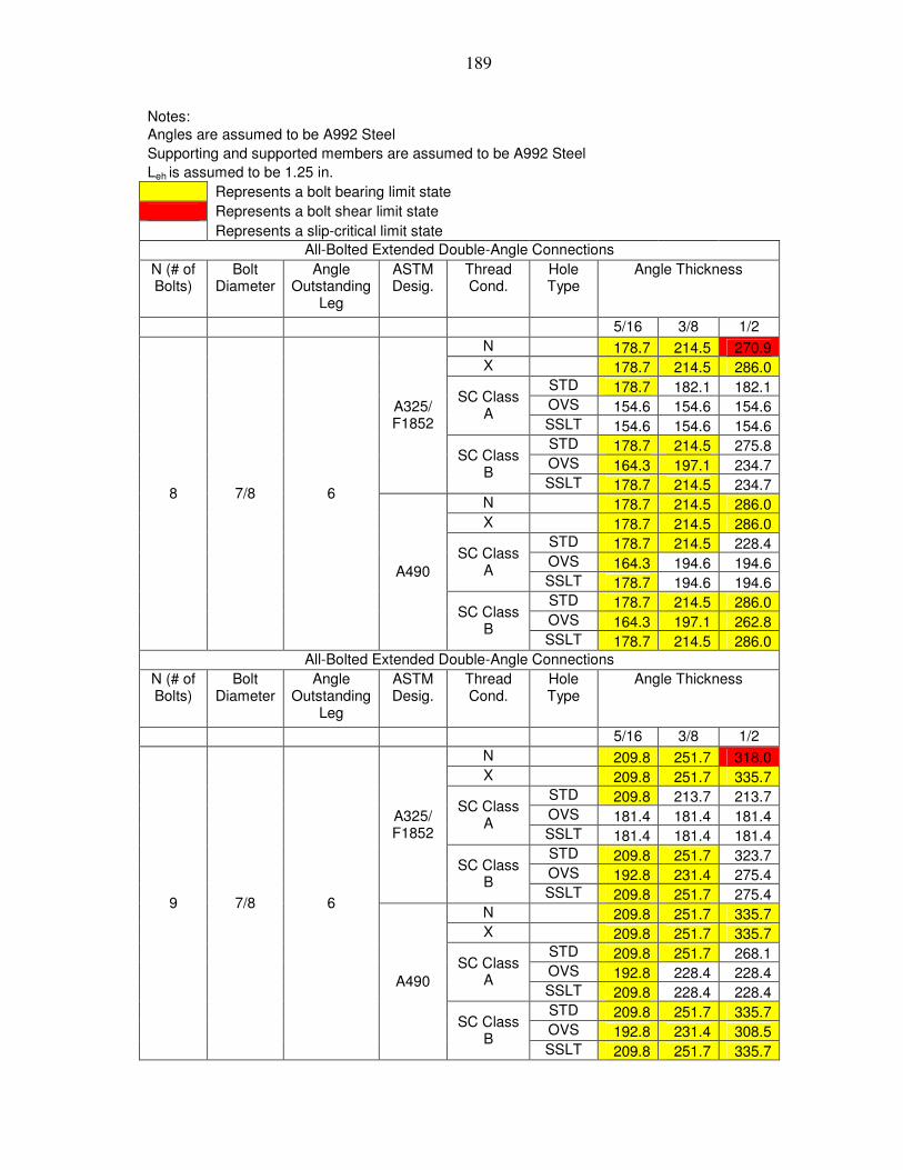
189
Notes: Angles are assumed to be A992 Steel Supporting and supported members are assumed to be A992 Steel Leh is assumed to be 1.25 in. Represents a bolt bearing limit state Represents a bolt shear limit state Represents a slip-critical limit state All-Bolted Extended Double-Angle Connections
N (# of Bolts)
Bolt Diameter
Angle Outstanding
Leg
ASTM Desig.
Thread Cond.
Hole Type
Angle Thickness
5/16 3/8 1/2 N 178.7 214.5 270.9 X 178.7 214.5 286.0 STD 178.7 182.1 182.1 OVS 154.6 154.6 154.6
SC Class A
SSLT 154.6 154.6 154.6 STD 178.7 214.5 275.8 OVS 164.3 197.1 234.7
A325/ F1852
SC Class B
SSLT 178.7 214.5 234.7 N 178.7 214.5 286.0 X 178.7 214.5 286.0 STD 178.7 214.5 228.4 OVS 164.3 194.6 194.6
SC Class A
SSLT 178.7 194.6 194.6 STD 178.7 214.5 286.0 OVS 164.3 197.1 262.8
8 7/8 6
A490
SC Class B
SSLT 178.7 214.5 286.0 All-Bolted Extended Double-Angle Connections
N (# of Bolts)
Bolt Diameter
Angle Outstanding
Leg
ASTM Desig.
Thread Cond.
Hole Type
Angle Thickness
5/16 3/8 1/2 N 209.8 251.7 318.0 X 209.8 251.7 335.7 STD 209.8 213.7 213.7 OVS 181.4 181.4 181.4
SC Class A
SSLT 181.4 181.4 181.4 STD 209.8 251.7 323.7 OVS 192.8 231.4 275.4
A325/ F1852
SC Class B
SSLT 209.8 251.7 275.4 N 209.8 251.7 335.7 X 209.8 251.7 335.7 STD 209.8 251.7 268.1 OVS 192.8 228.4 228.4
SC Class A
SSLT 209.8 228.4 228.4 STD 209.8 251.7 335.7 OVS 192.8 231.4 308.5
9 7/8 6
A490
SC Class B
SSLT 209.8 251.7 335.7

190
Notes: Angles are assumed to be A992 Steel Supporting and supported members are assumed to be A992 Steel Leh is assumed to be 1.25 in. Represents a bolt bearing limit state Represents a bolt shear limit state Represents a slip-critical limit state All-Bolted Extended Double-Angle Connections
N (# of Bolts)
Bolt Diameter
Angle Outstanding
Leg
ASTM Desig.
Thread Cond.
Hole Type
Angle Thickness
5/16 3/8 1/2 N 240.5 288.6 364.6 X 240.5 288.6 384.8 STD 240.5 245.0 245.0 OVS 208.0 208.0 208.0
SC Class A
SSLT 208.0 208.0 208.0 STD 240.5 288.6 371.1 OVS 221.0 265.2 315.8
A325/ F1852
SC Class B
SSLT 240.5 288.6 315.8 N 240.5 288.6 384.8 X 240.5 288.6 384.8 STD 240.5 288.6 307.3 OVS 221.0 261.9 261.9
SC Class A
SSLT 240.5 261.9 261.9 STD 240.5 288.6 384.8 OVS 221.0 265.2 353.6
10 7/8 6
A490
SC Class B
SSLT 240.5 288.6 384.8 All-Bolted Extended Double-Angle Connections
N (# of Bolts)
Bolt Diameter
Angle Outstanding
Leg
ASTM Desig.
Thread Cond.
Hole Type
Angle Thickness
5/16 3/8 1/2 N 271.2 325.4 411.1 X 271.2 325.4 433.9 STD 271.2 276.3 276.3 OVS 234.5 234.5 234.5
SC Class A
SSLT 234.5 234.5 234.5 STD 271.2 325.4 418.4 OVS 249.2 299.1 356.1
A325/ F1852
SC Class B
SSLT 271.2 325.4 356.1 N 271.2 325.4 433.9 X 271.2 325.4 433.9 STD 271.2 325.4 346.6 OVS 249.2 295.3 295.3
SC Class A
SSLT 271.2 295.3 295.3 STD 271.2 325.4 433.9 OVS 249.2 299.1 398.8
11 7/8 6
A490
SC Class B
SSLT 271.2 325.4 433.9

191
Notes: Angles are assumed to be A992 Steel Supporting and supported members are assumed to be A992 Steel Leh is assumed to be 1.25 in. Represents a bolt bearing limit state Represents a bolt shear limit state Represents a slip-critical limit state All-Bolted Extended Double-Angle Connections
N (# of Bolts)
Bolt Diameter
Angle Outstanding
Leg
ASTM Desig.
Thread Cond.
Hole Type
Angle Thickness
5/16 3/8 1/2 N 300.6 360.7 455.7 X 300.6 360.7 481.0 STD 300.6 306.3 306.3 OVS 260.0 260.0 260.0
SC Class A
SSLT 260.0 260.0 260.0 STD 300.6 360.7 463.8 OVS 276.3 331.5 394.7
A325/ F1852
SC Class B
SSLT 300.6 360.7 394.7 N 300.6 360.7 481.0 X 300.6 360.7 481.0 STD 300.6 360.7 384.2 OVS 276.3 327.3 327.3
SC Class A
SSLT 300.6 327.3 327.3 STD 300.6 360.7 481.0 OVS 276.3 331.5 442.1
12 7/8 6
A490
SC Class B
SSLT 300.6 360.7 481.0

192
Notes: Angles are assumed to be A992 Steel Supporting and supported members are assumed to be A992 Steel Leh is assumed to be 1.25 in. Represents a bolt bearing limit state Represents a bolt shear limit state Represents a slip-critical limit state All-Bolted Extended Double-Angle Connections
N (# of Bolts)
Bolt Diameter
Angle Outstanding
Leg
ASTM Desig.
Thread Cond.
Hole Type
Angle Thickness
5/16 3/8 1/2 N 14.3 17.1 21.7 X 14.3 17.1 22.9 STD 14.3 14.6 14.6 OVS 12.4 12.4 12.4
SC Class A
SSLT 12.4 12.4 12.4 STD 14.3 17.1 22.0 OVS 13.1 15.8 18.8
A325/ F1852
SC Class B
SSLT 14.3 17.1 18.8 N 14.3 17.1 22.9 X 14.3 17.1 22.9 STD 14.3 17.1 18.3 OVS 13.1 15.6 15.6
SC Class A
SSLT 14.3 15.6 15.6 STD 14.3 17.1 22.9 OVS 13.1 15.8 21.0
2 7/8 7
A490
SC Class B
SSLT 14.3 17.1 22.9 All-Bolted Extended Double-Angle Connections
N (# of Bolts)
Bolt Diameter
Angle Outstanding
Leg
ASTM Desig.
Thread Cond.
Hole Type
Angle Thickness
5/16 3/8 1/2 N 29.0 34.8 43.9 X 29.0 34.8 46.4 STD 29.0 29.5 29.5 OVS 25.1 25.1 25.1
SC Class A
SSLT 25.1 25.1 25.1 STD 29.0 34.8 44.7 OVS 26.6 32.0 38.1
A325/ F1852
SC Class B
SSLT 29.0 34.8 38.1 N 29.0 34.8 46.4 X 29.0 34.8 46.4 STD 29.0 34.8 37.0 OVS 26.6 31.6 31.6
SC Class A
SSLT 29.0 31.6 31.6 STD 29.0 34.8 46.4 OVS 26.6 32.0 42.6
3 7/8 7
A490
SC Class B
SSLT 29.0 34.8 46.4

193
Notes: Angles are assumed to be A992 Steel Supporting and supported members are assumed to be A992 Steel Leh is assumed to be 1.25 in. Represents a bolt bearing limit state Represents a bolt shear limit state Represents a slip-critical limit state All-Bolted Extended Double-Angle Connections
N (# of Bolts)
Bolt Diameter
Angle Outstanding
Leg
ASTM Desig.
Thread Cond.
Hole Type
Angle Thickness
5/16 3/8 1/2 N 52.1 62.5 78.9 X 52.1 62.5 83.3 STD 52.1 53.0 53.0 OVS 45.0 45.0 45.0
SC Class A
SSLT 45.0 45.0 45.0 STD 52.1 62.5 80.3 OVS 47.8 57.4 68.3
A325/ F1852
SC Class B
SSLT 52.1 62.5 68.3 N 52.1 62.5 83.3 X 52.1 62.5 83.3 STD 52.1 62.5 66.5 OVS 47.8 56.7 56.7
SC Class A
SSLT 52.1 56.7 56.7 STD 52.1 62.5 83.3 OVS 47.8 57.4 76.5
4 7/8 7
A490
SC Class B
SSLT 52.1 62.5 83.3 All-Bolted Extended Double-Angle Connections
N (# of Bolts)
Bolt Diameter
Angle Outstanding
Leg
ASTM Desig.
Thread Cond.
Hole Type
Angle Thickness
5/16 3/8 1/2 N 76.6 91.9 116.2 X 76.6 91.9 122.6 STD 76.6 78.1 78.1 OVS 66.3 66.3 66.3
SC Class A
SSLT 66.3 66.3 66.3 STD 76.6 91.9 118.2 OVS 70.4 84.5 100.6
A325/ F1852
SC Class B
SSLT 76.6 91.9 100.6 N 76.6 91.9 122.6 X 76.6 91.9 122.6 STD 76.6 91.9 97.9 OVS 70.4 83.4 83.4
SC Class A
SSLT 76.6 83.4 83.4 STD 76.6 91.9 122.6 OVS 70.4 84.5 112.7
5 7/8 7
A490
SC Class B
SSLT 76.6 91.9 122.6

194
Notes: Angles are assumed to be A992 Steel Supporting and supported members are assumed to be A992 Steel Leh is assumed to be 1.25 in. Represents a bolt bearing limit state Represents a bolt shear limit state Represents a slip-critical limit state All-Bolted Extended Double-Angle Connections
N (# of Bolts)
Bolt Diameter
Angle Outstanding
Leg
ASTM Desig.
Thread Cond.
Hole Type
Angle Thickness
5/16 3/8 1/2 N 104.5 125.4 158.4 X 104.5 125.4 167.1 STD 104.5 106.4 106.4 OVS 90.3 90.3 90.3
SC Class A
SSLT 90.3 90.3 90.3 STD 104.5 125.4 161.2 OVS 96.0 115.2 137.2
A325/ F1852
SC Class B
SSLT 104.5 125.4 137.2 N 104.5 125.4 167.1 X 104.5 125.4 167.1 STD 104.5 125.4 133.5 OVS 96.0 113.7 113.7
SC Class A
SSLT 104.5 113.7 113.7 STD 104.5 125.4 167.1 OVS 96.0 115.2 153.6
6 7/8 7
A490
SC Class B
SSLT 104.5 125.4 167.1 All-Bolted Extended Double-Angle Connections
N (# of Bolts)
Bolt Diameter
Angle Outstanding
Leg
ASTM Desig.
Thread Cond.
Hole Type
Angle Thickness
5/16 3/8 1/2 N 134.0 160.7 203.1 X 134.0 160.7 214.3 STD 134.0 136.5 136.5 OVS 115.8 115.8 115.8
SC Class A
SSLT 115.8 115.8 115.8 STD 134.0 160.7 206.7 OVS 123.1 147.7 175.9
A325/ F1852
SC Class B
SSLT 134.0 160.7 175.9 N 134.0 160.7 214.3 X 134.0 160.7 214.3 STD 134.0 160.7 171.2 OVS 123.1 145.9 145.9
SC Class A
SSLT 134.0 145.9 145.9 STD 134.0 160.7 214.3 OVS 123.1 147.7 197.0
7 7/8 7
A490
SC Class B
SSLT 134.0 160.7 214.3

195
Notes: Angles are assumed to be A992 Steel Supporting and supported members are assumed to be A992 Steel Leh is assumed to be 1.25 in. Represents a bolt bearing limit state Represents a bolt shear limit state Represents a slip-critical limit state All-Bolted Extended Double-Angle Connections
N (# of Bolts)
Bolt Diameter
Angle Outstanding
Leg
ASTM Desig.
Thread Cond.
Hole Type
Angle Thickness
5/16 3/8 1/2 N 164.4 197.3 249.2 X 164.4 197.3 263.0 STD 164.4 167.5 167.5 OVS 142.1 142.1 142.1
SC Class A
SSLT 142.1 142.1 142.1 STD 164.4 197.3 253.6 OVS 151.1 181.3 215.8
A325/ F1852
SC Class B
SSLT 164.4 197.3 215.8 N 164.4 197.3 263.0 X 164.4 197.3 263.0 STD 164.4 197.3 210.1 OVS 151.1 179.0 179.0
SC Class A
SSLT 164.4 179.0 179.0 STD 164.4 197.3 263.0 OVS 151.1 181.3 241.7
8 7/8 7
A490
SC Class B
SSLT 164.4 197.3 263.0 All-Bolted Extended Double-Angle Connections
N (# of Bolts)
Bolt Diameter
Angle Outstanding
Leg
ASTM Desig.
Thread Cond.
Hole Type
Angle Thickness
5/16 3/8 1/2 N 195.1 234.1 295.7 X 195.1 234.1 312.1 STD 195.1 198.8 198.8 OVS 168.7 168.7 168.7
SC Class A
SSLT 168.7 168.7 168.7 STD 195.1 234.1 301.0 OVS 179.3 215.1 256.1
A325/ F1852
SC Class B
SSLT 195.1 234.1 256.1 N 195.1 234.1 312.1 X 195.1 234.1 312.1 STD 195.1 234.1 249.3 OVS 179.3 212.4 212.4
SC Class A
SSLT 195.1 212.4 212.4 STD 195.1 234.1 312.1 OVS 179.3 215.1 286.9
9 7/8 7
A490
SC Class B
SSLT 195.1 234.1 312.1

196
Notes: Angles are assumed to be A992 Steel Supporting and supported members are assumed to be A992 Steel Leh is assumed to be 1.25 in. Represents a bolt bearing limit state Represents a bolt shear limit state Represents a slip-critical limit state All-Bolted Extended Double-Angle Connections
N (# of Bolts)
Bolt Diameter
Angle Outstanding
Leg
ASTM Desig.
Thread Cond.
Hole Type
Angle Thickness
5/16 3/8 1/2 N 226.1 271.4 342.8 X 226.1 271.4 361.8 STD 226.1 230.4 230.4 OVS 195.6 195.6 195.6
SC Class A
SSLT 195.6 195.6 195.6 STD 226.1 271.4 348.9 OVS 207.8 249.4 296.9
A325/ F1852
SC Class B
SSLT 226.1 271.4 296.9 N 226.1 271.4 361.8 X 226.1 271.4 361.8 STD 226.1 271.4 289.0 OVS 207.8 246.2 246.2
SC Class A
SSLT 226.1 246.2 246.2 STD 226.1 271.4 361.8 OVS 207.8 249.4 332.5
10 7/8 7
A490
SC Class B
SSLT 226.1 271.4 361.8 All-Bolted Extended Double-Angle Connections
N (# of Bolts)
Bolt Diameter
Angle Outstanding
Leg
ASTM Desig.
Thread Cond.
Hole Type
Angle Thickness
5/16 3/8 1/2 N 259.1 311.0 392.8 X 259.1 311.0 414.6 STD 259.1 264.0 264.0 OVS 224.1 224.1 224.1
SC Class A
SSLT 224.1 224.1 224.1 STD 259.1 311.0 399.8 OVS 238.2 285.8 340.2
A325/ F1852
SC Class B
SSLT 259.1 311.0 340.2 N 259.1 311.0 414.6 X 259.1 311.0 414.6 STD 259.1 311.0 331.1 OVS 238.2 282.2 282.2
SC Class A
SSLT 259.1 282.2 282.2 STD 259.1 311.0 414.6 OVS 238.2 285.8 381.0
11 7/8 7
A490
SC Class B
SSLT 259.1 311.0 414.6

197
Notes: Angles are assumed to be A992 Steel Supporting and supported members are assumed to be A992 Steel Leh is assumed to be 1.25 in. Represents a bolt bearing limit state Represents a bolt shear limit state Represents a slip-critical limit state All-Bolted Extended Double-Angle Connections
N (# of Bolts)
Bolt Diameter
Angle Outstanding
Leg
ASTM Desig.
Thread Cond.
Hole Type
Angle Thickness
5/16 3/8 1/2 N 287.6 345.1 436.0 X 287.6 345.1 460.2 STD 287.6 293.0 293.0 OVS 248.7 248.7 248.7
SC Class A
SSLT 248.7 248.7 248.7 STD 287.6 345.1 443.8 OVS 264.3 317.2 377.6
A325/ F1852
SC Class B
SSLT 287.6 345.1 377.6 N 287.6 345.1 460.2 X 287.6 345.1 460.2 STD 287.6 345.1 367.6 OVS 264.3 313.2 313.2
SC Class A
SSLT 287.6 313.2 313.2 STD 287.6 345.1 460.2 OVS 264.3 317.2 422.9
12 7/8 7
A490
SC Class B
SSLT 287.6 345.1 460.2

198
Notes: Angles are assumed to be A992 Steel Supporting and supported members are assumed to be A992 Steel Leh is assumed to be 1.25 in. Represents a bolt bearing limit state Represents a bolt shear limit state Represents a slip-critical limit state All-Bolted Extended Double-Angle Connections
N (# of Bolts)
Bolt Diameter
Angle Outstanding
Leg
ASTM Desig.
Thread Cond.
Hole Type
Angle Thickness
5/16 3/8 1/2 N 12.4 14.8 18.8 X 12.4 14.8 19.8 STD 12.4 12.6 12.6 OVS 10.7 10.7 10.7
SC Class A
SSLT 10.7 10.7 10.7 STD 12.4 14.8 19.1 OVS 11.4 13.6 16.2
A325/ F1852
SC Class B
SSLT 12.4 14.8 16.2 N 12.4 14.8 19.8 X 12.4 14.8 19.8 STD 12.4 14.8 15.8 OVS 11.4 13.5 13.5
SC Class A
SSLT 12.4 13.5 13.5 STD 12.4 14.8 19.8 OVS 11.4 13.6 18.2
2 7/8 8
A490
SC Class B
SSLT 12.4 14.8 19.8 All-Bolted Extended Double-Angle Connections
N (# of Bolts)
Bolt Diameter
Angle Outstanding
Leg
ASTM Desig.
Thread Cond.
Hole Type
Angle Thickness
5/16 3/8 1/2 N 25.0 30.0 37.9 X 25.0 30.0 40.0 STD 25.0 25.5 25.5 OVS 21.6 21.6 21.6
SC Class A
SSLT 21.6 21.6 21.6 STD 25.0 30.0 38.6 OVS 23.0 27.6 32.9
A325/ F1852
SC Class B
SSLT 25.0 30.0 32.9 N 25.0 30.0 40.0 X 25.0 30.0 40.0 STD 25.0 30.0 32.0 OVS 23.0 27.2 27.2
SC Class A
SSLT 25.0 27.2 27.2 STD 25.0 30.0 40.0 OVS 23.0 27.6 36.8
3 7/8 8
A490
SC Class B
SSLT 25.0 30.0 40.0

199
Notes: Angles are assumed to be A992 Steel Supporting and supported members are assumed to be A992 Steel Leh is assumed to be 1.25 in. Represents a bolt bearing limit state Represents a bolt shear limit state Represents a slip-critical limit state All-Bolted Extended Double-Angle Connections
N (# of Bolts)
Bolt Diameter
Angle Outstanding
Leg
ASTM Desig.
Thread Cond.
Hole Type
Angle Thickness
5/16 3/8 1/2 N 45.2 54.2 68.5 X 45.2 54.2 72.3 STD 45.2 46.1 46.1 OVS 39.1 39.1 39.1
SC Class A
SSLT 39.1 39.1 39.1 STD 45.2 54.2 69.7 OVS 41.5 49.9 59.3
A325/ F1852
SC Class B
SSLT 45.2 54.2 59.3 N 45.2 54.2 72.3 X 45.2 54.2 72.3 STD 45.2 54.2 57.8 OVS 41.5 49.2 49.2
SC Class A
SSLT 45.2 49.2 49.2 STD 45.2 54.2 72.3 OVS 41.5 49.9 66.5
4 7/8 8
A490
SC Class B
SSLT 45.2 54.2 72.3 All-Bolted Extended Double-Angle Connections
N (# of Bolts)
Bolt Diameter
Angle Outstanding
Leg
ASTM Desig.
Thread Cond.
Hole Type
Angle Thickness
5/16 3/8 1/2 N 68.0 81.7 103.2 X 68.0 81.7 108.9 STD 68.0 69.3 69.3 OVS 58.8 58.8 58.8
SC Class A
SSLT 58.8 58.8 58.8 STD 68.0 81.7 105.0 OVS 62.5 75.0 89.3
A325/ F1852
SC Class B
SSLT 68.0 81.7 89.3 N 68.0 81.7 108.9 X 68.0 81.7 108.9 STD 68.0 81.7 87.0 OVS 62.5 74.1 74.1
SC Class A
SSLT 68.0 74.1 74.1 STD 68.0 81.7 108.9 OVS 62.5 75.0 100.1
5 7/8 8
A490
SC Class B
SSLT 68.0 81.7 108.9

200
Notes: Angles are assumed to be A992 Steel Supporting and supported members are assumed to be A992 Steel Leh is assumed to be 1.25 in. Represents a bolt bearing limit state Represents a bolt shear limit state Represents a slip-critical limit state All-Bolted Extended Double-Angle Connections
N (# of Bolts)
Bolt Diameter
Angle Outstanding
Leg
ASTM Desig.
Thread Cond.
Hole Type
Angle Thickness
5/16 3/8 1/2 N 94.1 112.9 142.7 X 94.1 112.9 150.6 STD 94.1 95.9 95.9 OVS 81.4 81.4 81.4
SC Class A
SSLT 81.4 81.4 81.4 STD 94.1 112.9 145.2 OVS 86.5 103.8 123.6
A325/ F1852
SC Class B
SSLT 94.1 112.9 123.6 N 94.1 112.9 150.6 X 94.1 112.9 150.6 STD 94.1 112.9 120.3 OVS 86.5 102.5 102.5
SC Class A
SSLT 94.1 102.5 102.5 STD 94.1 112.9 150.6 OVS 86.5 103.8 138.4
6 7/8 8
A490
SC Class B
SSLT 94.1 112.9 150.6 All-Bolted Extended Double-Angle Connections
N (# of Bolts)
Bolt Diameter
Angle Outstanding
Leg
ASTM Desig.
Thread Cond.
Hole Type
Angle Thickness
5/16 3/8 1/2 N 122.1 146.5 185.1 X 122.1 146.5 195.4 STD 122.1 124.4 124.4 OVS 105.6 105.6 105.6
SC Class A
SSLT 105.6 105.6 105.6 STD 122.1 146.5 188.4 OVS 112.2 134.7 160.3
A325/ F1852
SC Class B
SSLT 122.1 146.5 160.3 N 122.1 146.5 195.4 X 122.1 146.5 195.4 STD 122.1 146.5 156.0 OVS 112.2 133.0 133.0
SC Class A
SSLT 122.1 133.0 133.0 STD 122.1 146.5 195.4 OVS 112.2 134.7 179.6
7 7/8 8
A490
SC Class B
SSLT 122.1 146.5 195.4

201
Notes: Angles are assumed to be A992 Steel Supporting and supported members are assumed to be A992 Steel Leh is assumed to be 1.25 in. Represents a bolt bearing limit state Represents a bolt shear limit state Represents a slip-critical limit state All-Bolted Extended Double-Angle Connections
N (# of Bolts)
Bolt Diameter
Angle Outstanding
Leg
ASTM Desig.
Thread Cond.
Hole Type
Angle Thickness
5/16 3/8 1/2 N 151.6 181.9 229.9 X 151.6 181.9 242.6 STD 151.6 154.5 154.5 OVS 131.1 131.1 131.1
SC Class A
SSLT 131.1 131.1 131.1 STD 151.6 181.9 233.9 OVS 139.3 167.2 199.1
A325/ F1852
SC Class B
SSLT 151.6 181.9 199.1 N 151.6 181.9 242.6 X 151.6 181.9 242.6 STD 151.6 181.9 193.8 OVS 139.3 165.1 165.1
SC Class A
SSLT 151.6 165.1 165.1 STD 151.6 181.9 242.6 OVS 139.3 167.2 223.0
8 7/8 8
A490
SC Class B
SSLT 151.6 181.9 242.6 All-Bolted Extended Double-Angle Connections
N (# of Bolts)
Bolt Diameter
Angle Outstanding
Leg
ASTM Desig.
Thread Cond.
Hole Type
Angle Thickness
5/16 3/8 1/2 N 181.8 218.2 275.6 X 181.8 218.2 290.9 STD 181.8 185.2 185.2 OVS 157.2 157.2 157.2
SC Class A
SSLT 157.2 157.2 157.2 STD 181.8 218.2 280.5 OVS 167.1 200.5 238.7
A325/ F1852
SC Class B
SSLT 181.8 218.2 238.7 N 181.8 218.2 290.9 X 181.8 218.2 290.9 STD 181.8 218.2 232.3 OVS 167.1 198.0 198.0
SC Class A
SSLT 181.8 198.0 198.0 STD 181.8 218.2 290.9 OVS 167.1 200.5 267.3
9 7/8 8
A490
SC Class B
SSLT 181.8 218.2 290.9

202
Notes: Angles are assumed to be A992 Steel Supporting and supported members are assumed to be A992 Steel Leh is assumed to be 1.25 in. Represents a bolt bearing limit state Represents a bolt shear limit state Represents a slip-critical limit state All-Bolted Extended Double-Angle Connections
N (# of Bolts)
Bolt Diameter
Angle Outstanding
Leg
ASTM Desig.
Thread Cond.
Hole Type
Angle Thickness
5/16 3/8 1/2 N 212.7 255.3 322.5 X 212.7 255.3 340.4 STD 212.7 216.7 216.7 OVS 184.0 184.0 184.0
SC Class A
SSLT 184.0 184.0 184.0 STD 212.7 255.3 328.2 OVS 195.5 234.6 279.3
A325/ F1852
SC Class B
SSLT 212.7 255.3 279.3 N 212.7 255.3 340.4 X 212.7 255.3 340.4 STD 212.7 255.3 271.9 OVS 195.5 231.6 231.6
SC Class A
SSLT 212.7 231.6 231.6 STD 212.7 255.3 340.4 OVS 195.5 234.6 312.8
10 7/8 8
A490
SC Class B
SSLT 212.7 255.3 340.4 All-Bolted Extended Double-Angle Connections
N (# of Bolts)
Bolt Diameter
Angle Outstanding
Leg
ASTM Desig.
Thread Cond.
Hole Type
Angle Thickness
5/16 3/8 1/2 N 243.6 292.3 369.3 X 243.6 292.3 389.7 STD 243.6 248.2 248.2 OVS 210.6 210.6 210.6
SC Class A
SSLT 210.6 210.6 210.6 STD 243.6 292.3 375.8 OVS 223.9 268.6 319.8
A325/ F1852
SC Class B
SSLT 243.6 292.3 319.8 N 243.6 292.3 389.7 X 243.6 292.3 389.7 STD 243.6 292.3 311.3 OVS 223.9 265.2 265.2
SC Class A
SSLT 243.6 265.2 265.2 STD 243.6 292.3 389.7 OVS 223.9 268.6 358.2
11 7/8 8
A490
SC Class B
SSLT 243.6 292.3 389.7

203
Notes: Angles are assumed to be A992 Steel Supporting and supported members are assumed to be A992 Steel Leh is assumed to be 1.25 in. Represents a bolt bearing limit state Represents a bolt shear limit state Represents a slip-critical limit state All-Bolted Extended Double-Angle Connections
N (# of Bolts)
Bolt Diameter
Angle Outstanding
Leg
ASTM Desig.
Thread Cond.
Hole Type
Angle Thickness
5/16 3/8 1/2 N 274.5 329.4 416.2 X 274.5 329.4 439.3 STD 274.5 279.7 279.7 OVS 237.4 237.4 237.4
SC Class A
SSLT 237.4 237.4 237.4 STD 274.5 329.4 423.6 OVS 252.3 302.8 360.4
A325/ F1852
SC Class B
SSLT 274.5 329.4 360.4 N 274.5 329.4 439.3 X 274.5 329.4 439.3 STD 274.5 329.4 350.8 OVS 252.3 298.9 298.9
SC Class A
SSLT 274.5 298.9 298.9 STD 274.5 329.4 439.3 OVS 252.3 302.8 403.7
12 7/8 8
A490
SC Class B
SSLT 274.5 329.4 439.3

204
Notes: Angles are assumed to be A992 Steel Supporting and supported members are assumed to be A992 Steel Leh is assumed to be 1.25 in. Represents a bolt bearing limit state Represents a bolt shear limit state Represents a slip-critical limit state All-Bolted Extended Double-Angle Connections
N (# of Bolts)
Bolt Diameter
Angle Outstanding
Leg
ASTM Desig.
Thread Cond.
Hole Type
Angle Thickness
5/16 3/8 1/2 N 9.3 11.1 14.1 X 9.3 11.1 14.9 STD 9.3 9.5 9.5 OVS 8.0 8.0 8.0
SC Class A
SSLT 8.0 8.0 8.0 STD 9.3 11.1 14.3 OVS 8.5 10.2 12.2
A325/ F1852
SC Class B
SSLT 9.3 11.1 12.2 N 9.3 11.1 14.9 X 9.3 11.1 14.9 STD 9.3 11.1 11.9 OVS 8.5 10.1 10.1
SC Class A
SSLT 9.3 10.1 10.1 STD 9.3 11.1 14.9 OVS 8.5 10.2 13.7
2 7/8 9
A490
SC Class B
SSLT 9.3 11.1 14.9 All-Bolted Extended Double-Angle Connections
N (# of Bolts)
Bolt Diameter
Angle Outstanding
Leg
ASTM Desig.
Thread Cond.
Hole Type
Angle Thickness
5/16 3/8 1/2 N 21.6 25.9 32.7 X 21.6 25.9 34.5 STD 21.6 22.0 22.0 OVS 18.6 18.6 18.6
SC Class A
SSLT 18.6 18.6 18.6 STD 21.6 25.9 33.3 OVS 19.8 23.8 28.3
A325/ F1852
SC Class B
SSLT 21.6 25.9 28.3 N 21.6 25.9 34.5 X 21.6 25.9 34.5 STD 21.6 25.9 27.6 OVS 19.8 23.5 23.5
SC Class A
SSLT 21.6 23.5 23.5 STD 21.6 25.9 34.5 OVS 19.8 23.8 31.7
3 7/8 9
A490
SC Class B
SSLT 21.6 25.9 34.5

205
Notes: Angles are assumed to be A992 Steel Supporting and supported members are assumed to be A992 Steel Leh is assumed to be 1.25 in. Represents a bolt bearing limit state Represents a bolt shear limit state Represents a slip-critical limit state All-Bolted Extended Double-Angle Connections
N (# of Bolts)
Bolt Diameter
Angle Outstanding
Leg
ASTM Desig.
Thread Cond.
Hole Type
Angle Thickness
5/16 3/8 1/2 N 39.5 47.4 59.9 X 39.5 47.4 63.2 STD 39.5 40.2 40.2 OVS 34.1 34.1 34.1
SC Class A
SSLT 34.1 34.1 34.1 STD 39.5 47.4 60.9 OVS 36.3 43.5 51.8
A325/ F1852
SC Class B
SSLT 39.5 47.4 51.8 N 39.5 47.4 63.2 X 39.5 47.4 63.2 STD 39.5 47.4 50.5 OVS 36.3 43.0 43.0
SC Class A
SSLT 39.5 43.0 43.0 STD 39.5 47.4 63.2 OVS 36.3 43.5 58.1
4 7/8 9
A490
SC Class B
SSLT 39.5 47.4 63.2 All-Bolted Extended Double-Angle Connections
N (# of Bolts)
Bolt Diameter
Angle Outstanding
Leg
ASTM Desig.
Thread Cond.
Hole Type
Angle Thickness
5/16 3/8 1/2 N 60.0 72.0 90.9 X 60.0 72.0 96.0 STD 60.0 61.1 61.1 OVS 51.9 51.9 51.9
SC Class A
SSLT 51.9 51.9 51.9 STD 60.0 72.0 92.5 OVS 55.1 66.2 78.8
A325/ F1852
SC Class B
SSLT 60.0 72.0 78.8 N 60.0 72.0 96.0 X 60.0 72.0 96.0 STD 60.0 72.0 76.7 OVS 55.1 65.3 65.3
SC Class A
SSLT 60.0 65.3 65.3 STD 60.0 72.0 96.0 OVS 55.1 66.2 88.2
5 7/8 9
A490
SC Class B
SSLT 60.0 72.0 96.0

206
Notes: Angles are assumed to be A992 Steel Supporting and supported members are assumed to be A992 Steel Leh is assumed to be 1.25 in. Represents a bolt bearing limit state Represents a bolt shear limit state Represents a slip-critical limit state All-Bolted Extended Double-Angle Connections
N (# of Bolts)
Bolt Diameter
Angle Outstanding
Leg
ASTM Desig.
Thread Cond.
Hole Type
Angle Thickness
5/16 3/8 1/2 N 83.7 100.4 126.9 X 83.7 100.4 133.9 STD 83.7 85.3 85.3 OVS 72.4 72.4 72.4
SC Class A
SSLT 72.4 72.4 72.4 STD 83.7 100.4 129.1 OVS 76.9 92.3 109.9
A325/ F1852
SC Class B
SSLT 83.7 100.4 109.9 N 83.7 100.4 133.9 X 83.7 100.4 133.9 STD 83.7 100.4 106.9 OVS 76.9 91.1 91.1
SC Class A
SSLT 83.7 91.1 91.1 STD 83.7 100.4 133.9 OVS 76.9 92.3 123.1
6 7/8 9
A490
SC Class B
SSLT 83.7 100.4 133.9 All-Bolted Extended Double-Angle Connections
N (# of Bolts)
Bolt Diameter
Angle Outstanding
Leg
ASTM Desig.
Thread Cond.
Hole Type
Angle Thickness
5/16 3/8 1/2 N 109.8 131.8 166.5 X 109.8 131.8 175.7 STD 109.8 111.9 111.9 OVS 95.0 95.0 95.0
SC Class A
SSLT 95.0 95.0 95.0 STD 109.8 131.8 169.4 OVS 100.9 121.1 144.2
A325/ F1852
SC Class B
SSLT 109.8 131.8 144.2 N 109.8 131.8 175.7 X 109.8 131.8 175.7 STD 109.8 131.8 140.3 OVS 100.9 119.6 119.6
SC Class A
SSLT 109.8 119.6 119.6 STD 109.8 131.8 175.7 OVS 100.9 121.1 161.5
7 7/8 9
A490
SC Class B
SSLT 109.8 131.8 175.7

207
Notes: Angles are assumed to be A992 Steel Supporting and supported members are assumed to be A992 Steel Leh is assumed to be 1.25 in. Represents a bolt bearing limit state Represents a bolt shear limit state Represents a slip-critical limit state All-Bolted Extended Double-Angle Connections
N (# of Bolts)
Bolt Diameter
Angle Outstanding
Leg
ASTM Desig.
Thread Cond.
Hole Type
Angle Thickness
5/16 3/8 1/2 N 137.9 165.5 209.0 X 137.9 165.5 220.6 STD 137.9 140.5 140.5 OVS 119.2 119.2 119.2
SC Class A
SSLT 119.2 119.2 119.2 STD 137.9 165.5 212.7 OVS 126.7 152.1 181.0
A325/ F1852
SC Class B
SSLT 137.9 165.5 181.0 N 137.9 165.5 220.6 X 137.9 165.5 220.6 STD 137.9 165.5 176.2 OVS 126.7 150.1 150.1
SC Class A
SSLT 137.9 150.1 150.1 STD 137.9 165.5 220.6 OVS 126.7 152.1 202.8
8 7/8 9
A490
SC Class B
SSLT 137.9 165.5 220.6 All-Bolted Extended Double-Angle Connections
N (# of Bolts)
Bolt Diameter
Angle Outstanding
Leg
ASTM Desig.
Thread Cond.
Hole Type
Angle Thickness
5/16 3/8 1/2 N 167.0 200.4 253.2 X 167.0 200.4 267.2 STD 167.0 170.2 170.2 OVS 144.4 144.4 144.4
SC Class A
SSLT 144.4 144.4 144.4 STD 167.0 200.4 257.7 OVS 153.5 184.2 219.3
A325/ F1852
SC Class B
SSLT 167.0 200.4 219.3 N 167.0 200.4 267.2 X 167.0 200.4 267.2 STD 167.0 200.4 213.4 OVS 153.5 181.9 181.9
SC Class A
SSLT 167.0 181.9 181.9 STD 167.0 200.4 267.2 OVS 153.5 184.2 245.6
9 7/8 9
A490
SC Class B
SSLT 167.0 200.4 267.2

208
Notes: Angles are assumed to be A992 Steel Supporting and supported members are assumed to be A992 Steel Leh is assumed to be 1.25 in. Represents a bolt bearing limit state Represents a bolt shear limit state Represents a slip-critical limit state All-Bolted Extended Double-Angle Connections
N (# of Bolts)
Bolt Diameter
Angle Outstanding
Leg
ASTM Desig.
Thread Cond.
Hole Type
Angle Thickness
5/16 3/8 1/2 N 197.2 236.7 299.0 X 197.2 236.7 315.6 STD 197.2 200.9 200.9 OVS 170.6 170.6 170.6
SC Class A
SSLT 170.6 170.6 170.6 STD 197.2 236.7 304.3 OVS 181.3 217.5 258.9
A325/ F1852
SC Class B
SSLT 197.2 236.7 258.9 N 197.2 236.7 315.6 X 197.2 236.7 315.6 STD 197.2 236.7 252.0 OVS 181.3 214.7 214.7
SC Class A
SSLT 197.2 214.7 214.7 STD 197.2 236.7 315.6 OVS 181.3 217.5 290.0
10 7/8 9
A490
SC Class B
SSLT 197.2 236.7 315.6 All-Bolted Extended Double-Angle Connections
N (# of Bolts)
Bolt Diameter
Angle Outstanding
Leg
ASTM Desig.
Thread Cond.
Hole Type
Angle Thickness
5/16 3/8 1/2 N 227.9 273.4 345.4 X 227.9 273.4 364.6 STD 227.9 232.1 232.1 OVS 197.0 197.0 197.0
SC Class A
SSLT 197.0 197.0 197.0 STD 227.9 273.4 351.6 OVS 209.4 251.3 299.2
A325/ F1852
SC Class B
SSLT 227.9 273.4 299.2 N 227.9 273.4 364.6 X 227.9 273.4 364.6 STD 227.9 273.4 291.2 OVS 209.4 248.1 248.1
SC Class A
SSLT 227.9 248.1 248.1 STD 227.9 273.4 364.6 OVS 209.4 251.3 335.1
11 7/8 9
A490
SC Class B
SSLT 227.9 273.4 364.6

209
Notes: Angles are assumed to be A992 Steel Supporting and supported members are assumed to be A992 Steel Leh is assumed to be 1.25 in. Represents a bolt bearing limit state Represents a bolt shear limit state Represents a slip-critical limit state All-Bolted Extended Double-Angle Connections
N (# of Bolts)
Bolt Diameter
Angle Outstanding
Leg
ASTM Desig.
Thread Cond.
Hole Type
Angle Thickness
5/16 3/8 1/2 N 258.7 310.4 392.2 X 258.7 310.4 413.9 STD 258.7 263.6 263.6 OVS 223.7 223.7 223.7
SC Class A
SSLT 223.7 223.7 223.7 STD 258.7 310.4 399.2 OVS 237.8 285.3 339.7
A325/ F1852
SC Class B
SSLT 258.7 310.4 339.7 N 258.7 310.4 413.9 X 258.7 310.4 413.9 STD 258.7 310.4 330.6 OVS 237.8 281.7 281.7
SC Class A
SSLT 258.7 281.7 281.7 STD 258.7 310.4 413.9 OVS 237.8 285.3 380.4
12 7/8 9
A490
SC Class B
SSLT 258.7 310.4 413.9

210
APPENDIX F 1-INCH DIAMETER ALL-BOLTED A992 STEEL DOUBLE ANGLE
CONNECTIONS
The tables given in Appendix F are all-bolted double angle connections. The
angles are A992 angles using either A325/F1852 or A490 1-inch diameter bolts.

211
Notes: Angles are assumed to be A992 Steel Supporting and supported members are assumed to be A992 Steel Leh is assumed to be 1.25 in. Represents a bolt bearing limit state Represents a bolt shear limit state Represents a slip-critical limit state All-Bolted Extended Double-Angle Connections
N (# of Bolts)
Bolt Diameter
Angle Outstanding
Leg
ASTM Desig.
Thread Cond.
Hole Type
Angle Thickness
5/16 3/8 1/2 N 14.2 17.1 22.8 X 14.2 17.1 22.8 STD 14.2 17.1 20.6 OVS 12.4 14.9 17.5
SC Class A
SSLT 14.2 17.1 17.5 STD 14.2 17.1 22.8 OVS 12.4 14.9 19.9
A325/ F1852
SC Class B
SSLT 14.2 17.1 22.8 N 14.2 17.1 22.8 X 14.2 17.1 22.8 STD 14.2 17.1 22.8 OVS 12.4 14.9 22.0
SC Class A
SSLT 14.2 17.1 22.0 STD 14.2 17.1 22.8 OVS 12.4 14.9 19.9
2 1 6
A490
SC Class B
SSLT 14.2 17.1 22.8 All-Bolted Extended Double-Angle Connections
N (# of Bolts)
Bolt Diameter
Angle Outstanding
Leg
ASTM Desig.
Thread Cond.
Hole Type
Angle Thickness
5/16 3/8 1/2 N 31.8 38.2 50.9 X 31.8 38.2 50.9 STD 31.8 38.2 46.1 OVS 27.7 33.3 39.2
SC Class A
SSLT 31.8 38.2 39.2 STD 31.8 38.2 50.9 OVS 27.7 33.3 44.4
A325/ F1852
SC Class B
SSLT 31.8 38.2 50.9 N 31.8 38.2 50.9 X 31.8 38.2 50.9 STD 31.8 38.2 50.9 OVS 27.7 33.3 49.2
SC Class A
SSLT 31.8 38.2 49.2 STD 31.8 38.2 50.9 OVS 27.7 33.3 44.4
3 1 6
A490
SC Class B
SSLT 31.8 38.2 50.9

212
Notes: Angles are assumed to be A992 Steel Supporting and supported members are assumed to be A992 Steel Leh is assumed to be 1.25 in. Represents a bolt bearing limit state Represents a bolt shear limit state Represents a slip-critical limit state All-Bolted Extended Double-Angle Connections
N (# of Bolts)
Bolt Diameter
Angle Outstanding
Leg
ASTM Desig.
Thread Cond.
Hole Type
Angle Thickness
5/16 3/8 1/2 N 55.1 66.1 88.1 X 55.1 66.1 88.1 STD 55.1 66.1 79.7 OVS 48.0 57.6 67.7
SC Class A
SSLT 55.1 66.1 67.7 STD 55.1 66.1 88.1 OVS 48.0 57.6 76.8
A325/ F1852
SC Class B
SSLT 55.1 66.1 88.1 N 55.1 66.1 88.1 X 55.1 66.1 88.1 STD 55.1 66.1 88.1 OVS 48.0 57.6 85.2
SC Class A
SSLT 55.1 66.1 85.2 STD 55.1 66.1 88.1 OVS 48.0 57.6 76.8
4 1 6
A490
SC Class B
SSLT 55.1 66.1 88.1 All-Bolted Extended Double-Angle Connections
N (# of Bolts)
Bolt Diameter
Angle Outstanding
Leg
ASTM Desig.
Thread Cond.
Hole Type
Angle Thickness
5/16 3/8 1/2 N 80.6 96.7 128.9 X 80.6 96.7 128.9 STD 80.6 96.7 116.7 OVS 70.2 84.3 99.2
SC Class A
SSLT 80.6 96.7 99.2 STD 80.6 96.7 128.9 OVS 70.2 84.3 112.4
A325/ F1852
SC Class B
SSLT 80.6 96.7 128.9 N 80.6 96.7 128.9 X 80.6 96.7 128.9 STD 80.6 96.7 128.9 OVS 70.2 84.3 124.6
SC Class A
SSLT 80.6 96.7 124.6 STD 80.6 96.7 128.9 OVS 70.2 84.3 112.4
5 1 6
A490
SC Class B
SSLT 80.6 96.7 128.9

213
Notes: Angles are assumed to be A992 Steel Supporting and supported members are assumed to be A992 Steel Leh is assumed to be 1.25 in. Represents a bolt bearing limit state Represents a bolt shear limit state Represents a slip-critical limit state All-Bolted Extended Double-Angle Connections
N (# of Bolts)
Bolt Diameter
Angle Outstanding
Leg
ASTM Desig.
Thread Cond.
Hole Type
Angle Thickness
5/16 3/8 1/2 N 107.7 129.2 172.3 X 107.7 129.2 172.3 STD 107.7 129.2 155.9 OVS 93.8 112.6 132.5
SC Class A
SSLT 107.7 129.2 132.5 STD 107.7 129.2 172.3 OVS 93.8 112.6 150.2
A325/ F1852
SC Class B
SSLT 107.7 129.2 172.3 N 107.7 129.2 172.3 X 107.7 129.2 172.3 STD 107.7 129.2 172.3 OVS 93.8 112.6 166.6
SC Class A
SSLT 107.7 129.2 166.6 STD 107.7 129.2 172.3 OVS 93.8 112.6 150.2
6 1 6
A490
SC Class B
SSLT 107.7 129.2 172.3 All-Bolted Extended Double-Angle Connections
N (# of Bolts)
Bolt Diameter
Angle Outstanding
Leg
ASTM Desig.
Thread Cond.
Hole Type
Angle Thickness
5/16 3/8 1/2 N 136.1 163.3 217.8 X 136.1 163.3 217.8 STD 136.1 163.3 197.0 OVS 118.6 142.3 167.5
SC Class A
SSLT 136.1 163.3 167.5 STD 136.1 163.3 217.8 OVS 118.6 142.3 189.8
A325/ F1852
SC Class B
SSLT 136.1 163.3 217.8 N 136.1 163.3 217.8 X 136.1 163.3 217.8 STD 136.1 163.3 217.8 OVS 118.6 142.3 210.5
SC Class A
SSLT 136.1 163.3 210.5 STD 136.1 163.3 217.8 OVS 118.6 142.3 189.8
7 1 6
A490
SC Class B
SSLT 136.1 163.3 217.8

214
Notes: Angles are assumed to be A992 Steel Supporting and supported members are assumed to be A992 Steel Leh is assumed to be 1.25 in. Represents a bolt bearing limit state Represents a bolt shear limit state Represents a slip-critical limit state All-Bolted Extended Double-Angle Connections
N (# of Bolts)
Bolt Diameter
Angle Outstanding
Leg
ASTM Desig.
Thread Cond.
Hole Type
Angle Thickness
5/16 3/8 1/2 N 164.3 197.1 262.8 X 164.3 197.1 262.8 STD 164.3 197.1 237.8 OVS 143.1 171.8 202.1
SC Class A
SSLT 164.3 197.1 202.1 STD 164.3 197.1 262.8 OVS 143.1 171.8 229.0
A325/ F1852
SC Class B
SSLT 164.3 197.1 262.8 N 164.3 197.1 262.8 X 164.3 197.1 262.8 STD 164.3 197.1 262.8 OVS 143.1 171.8 254.1
SC Class A
SSLT 164.3 197.1 254.1 STD 164.3 197.1 262.8 OVS 143.1 171.8 229.0
8 1 6
A490
SC Class B
SSLT 164.3 197.1 262.8 All-Bolted Extended Double-Angle Connections
N (# of Bolts)
Bolt Diameter
Angle Outstanding
Leg
ASTM Desig.
Thread Cond.
Hole Type
Angle Thickness
5/16 3/8 1/2 N 192.8 231.4 308.5 X 192.8 231.4 308.5 STD 192.8 231.4 279.1 OVS 168.0 201.6 237.2
SC Class A
SSLT 192.8 231.4 237.2 STD 192.8 231.4 308.5 OVS 168.0 201.6 268.8
A325/ F1852
SC Class B
SSLT 192.8 231.4 308.5 N 192.8 231.4 308.5 X 192.8 231.4 308.5 STD 192.8 231.4 308.5 OVS 168.0 201.6 298.2
SC Class A
SSLT 192.8 231.4 298.2 STD 192.8 231.4 308.5 OVS 168.0 201.6 268.8
9 1 6
A490
SC Class B
SSLT 192.8 231.4 308.5

215
Notes: Angles are assumed to be A992 Steel Supporting and supported members are assumed to be A992 Steel Leh is assumed to be 1.25 in. Represents a bolt bearing limit state Represents a bolt shear limit state Represents a slip-critical limit state All-Bolted Extended Double-Angle Connections
N (# of Bolts)
Bolt Diameter
Angle Outstanding
Leg
ASTM Desig.
Thread Cond.
Hole Type
Angle Thickness
5/16 3/8 1/2 N 221.0 265.2 353.6 X 221.0 265.2 353.6 STD 221.0 265.2 320.0 OVS 192.6 231.1 272.0
SC Class A
SSLT 221.0 265.2 272.0 STD 221.0 265.2 353.6 OVS 192.6 231.1 308.2
A325/ F1852
SC Class B
SSLT 221.0 265.2 353.6 N 221.0 265.2 353.6 X 221.0 265.2 353.6 STD 221.0 265.2 353.6 OVS 192.6 231.1 341.9
SC Class A
SSLT 221.0 265.2 341.9 STD 221.0 265.2 353.6 OVS 192.6 231.1 308.2
10 1 6
A490
SC Class B
SSLT 221.0 265.2 353.6 All-Bolted Extended Double-Angle Connections
N (# of Bolts)
Bolt Diameter
Angle Outstanding
Leg
ASTM Desig.
Thread Cond.
Hole Type
Angle Thickness
5/16 3/8 1/2 N 249.2 299.1 398.8 X 249.2 299.1 398.8 STD 249.2 299.1 360.8 OVS 217.2 260.6 306.7
SC Class A
SSLT 249.2 299.1 306.7 STD 249.2 299.1 398.8 OVS 217.2 260.6 347.5
A325/ F1852
SC Class B
SSLT 249.2 299.1 398.8 N 249.2 299.1 398.8 X 249.2 299.1 398.8 STD 249.2 299.1 398.8 OVS 217.2 260.6 385.5
SC Class A
SSLT 249.2 299.1 385.5 STD 249.2 299.1 398.8 OVS 217.2 260.6 347.5
11 1 6
A490
SC Class B
SSLT 249.2 299.1 398.8

216
Notes: Angles are assumed to be A992 Steel Supporting and supported members are assumed to be A992 Steel Leh is assumed to be 1.25 in. Represents a bolt bearing limit state Represents a bolt shear limit state Represents a slip-critical limit state All-Bolted Extended Double-Angle Connections
N (# of Bolts)
Bolt Diameter
Angle Outstanding
Leg
ASTM Desig.
Thread Cond.
Hole Type
Angle Thickness
5/16 3/8 1/2 N 276.3 331.5 442.1 X 276.3 331.5 442.1 STD 276.3 331.5 400.0 OVS 240.8 288.9 340.0
SC Class A
SSLT 276.3 331.5 340.0 STD 276.3 331.5 442.1 OVS 240.8 288.9 385.2
A325/ F1852
SC Class B
SSLT 276.3 331.5 442.1 N 276.3 331.5 442.1 X 276.3 331.5 442.1 STD 276.3 331.5 442.1 OVS 240.8 288.9 427.3
SC Class A
SSLT 276.3 331.5 427.3 STD 276.3 331.5 442.1 OVS 240.8 288.9 385.2
12 1 6
A490
SC Class B
SSLT 276.3 331.5 442.1

217
Notes: Angles are assumed to be A992 Steel Supporting and supported members are assumed to be A992 Steel Leh is assumed to be 1.25 in. Represents a bolt bearing limit state Represents a bolt shear limit state Represents a slip-critical limit state All-Bolted Extended Double-Angle Connections
N (# of Bolts)
Bolt Diameter
Angle Outstanding
Leg
ASTM Desig.
Thread Cond.
Hole Type
Angle Thickness
5/16 3/8 1/2 N 13.1 15.8 21.0 X 13.1 15.8 21.0 STD 13.1 15.8 19.0 OVS 11.4 13.7 16.2
SC Class A
SSLT 13.1 15.8 16.2 STD 13.1 15.8 21.0 OVS 11.4 13.7 18.3
A325/ F1852
SC Class B
SSLT 13.1 15.8 21.0 N 13.1 15.8 21.0 X 13.1 15.8 21.0 STD 13.1 15.8 21.0 OVS 11.4 13.7 20.3
SC Class A
SSLT 13.1 15.8 20.3 STD 13.1 15.8 21.0 OVS 11.4 13.7 18.3
2 1 7
A490
SC Class B
SSLT 13.1 15.8 21.0 All-Bolted Extended Double-Angle Connections
N (# of Bolts)
Bolt Diameter
Angle Outstanding
Leg
ASTM Desig.
Thread Cond.
Hole Type
Angle Thickness
5/16 3/8 1/2 N 26.6 32.0 42.6 X 26.6 32.0 42.6 STD 26.6 32.0 38.6 OVS 23.2 27.9 32.8
SC Class A
SSLT 26.6 32.0 32.8 STD 26.6 32.0 42.6 OVS 23.2 27.9 37.1
A325/ F1852
SC Class B
SSLT 26.6 32.0 42.6 N 26.6 32.0 42.6 X 26.6 32.0 42.6 STD 26.6 32.0 42.6 OVS 23.2 27.9 41.2
SC Class A
SSLT 26.6 32.0 41.2 STD 26.6 32.0 42.6 OVS 23.2 27.9 37.1
3 1 7
A490
SC Class B
SSLT 26.6 32.0 42.6

218
Notes: Angles are assumed to be A992 Steel Supporting and supported members are assumed to be A992 Steel Leh is assumed to be 1.25 in. Represents a bolt bearing limit state Represents a bolt shear limit state Represents a slip-critical limit state All-Bolted Extended Double-Angle Connections
N (# of Bolts)
Bolt Diameter
Angle Outstanding
Leg
ASTM Desig.
Thread Cond.
Hole Type
Angle Thickness
5/16 3/8 1/2 N 47.8 57.4 76.5 X 47.8 57.4 76.5 STD 47.8 57.4 69.3 OVS 41.7 50.0 58.9
SC Class A
SSLT 47.8 57.4 58.9 STD 47.8 57.4 76.5 OVS 41.7 50.0 66.7
A325/ F1852
SC Class B
SSLT 47.8 57.4 76.5 N 47.8 57.4 76.5 X 47.8 57.4 76.5 STD 47.8 57.4 76.5 OVS 41.7 50.0 74.0
SC Class A
SSLT 47.8 57.4 74.0 STD 47.8 57.4 76.5 OVS 41.7 50.0 66.7
4 1 7
A490
SC Class B
SSLT 47.8 57.4 76.5 All-Bolted Extended Double-Angle Connections
N (# of Bolts)
Bolt Diameter
Angle Outstanding
Leg
ASTM Desig.
Thread Cond.
Hole Type
Angle Thickness
5/16 3/8 1/2 N 70.4 84.5 112.7 X 70.4 84.5 112.7 STD 70.4 84.5 101.9 OVS 61.4 73.6 86.6
SC Class A
SSLT 70.4 84.5 86.6 STD 70.4 84.5 112.7 OVS 61.4 73.6 98.2
A325/ F1852
SC Class B
SSLT 70.4 84.5 112.7 N 70.4 84.5 112.7 X 70.4 84.5 112.7 STD 70.4 84.5 112.7 OVS 61.4 73.6 108.9
SC Class A
SSLT 70.4 84.5 108.9 STD 70.4 84.5 112.7 OVS 61.4 73.6 98.2
5 1 7
A490
SC Class B
SSLT 70.4 84.5 112.7

219
Notes: Angles are assumed to be A992 Steel Supporting and supported members are assumed to be A992 Steel Leh is assumed to be 1.25 in. Represents a bolt bearing limit state Represents a bolt shear limit state Represents a slip-critical limit state All-Bolted Extended Double-Angle Connections
N (# of Bolts)
Bolt Diameter
Angle Outstanding
Leg
ASTM Desig.
Thread Cond.
Hole Type
Angle Thickness
5/16 3/8 1/2 N 96.0 115.2 153.6 X 96.0 115.2 153.6 STD 96.0 115.2 139.0 OVS 83.7 100.4 118.1
SC Class A
SSLT 96.0 115.2 118.1 STD 96.0 115.2 153.6 OVS 83.7 100.4 133.9
A325/ F1852
SC Class B
SSLT 96.0 115.2 153.6 N 96.0 115.2 153.6 X 96.0 115.2 153.6 STD 96.0 115.2 153.6 OVS 83.7 100.4 148.5
SC Class A
SSLT 96.0 115.2 148.5 STD 96.0 115.2 153.6 OVS 83.7 100.4 133.9
6 1 7
A490
SC Class B
SSLT 96.0 115.2 153.6 All-Bolted Extended Double-Angle Connections
N (# of Bolts)
Bolt Diameter
Angle Outstanding
Leg
ASTM Desig.
Thread Cond.
Hole Type
Angle Thickness
5/16 3/8 1/2 N 123.1 147.7 197.0 X 123.1 147.7 197.0 STD 123.1 147.7 178.2 OVS 107.3 128.7 151.5
SC Class A
SSLT 123.1 147.7 151.5 STD 123.1 147.7 197.0 OVS 107.3 128.7 171.7
A325/ F1852
SC Class B
SSLT 123.1 147.7 197.0 N 123.1 147.7 197.0 X 123.1 147.7 197.0 STD 123.1 147.7 197.0 OVS 107.3 128.7 190.4
SC Class A
SSLT 123.1 147.7 190.4 STD 123.1 147.7 197.0 OVS 107.3 128.7 171.7
7 1 7
A490
SC Class B
SSLT 123.1 147.7 197.0

220
Notes: Angles are assumed to be A992 Steel Supporting and supported members are assumed to be A992 Steel Leh is assumed to be 1.25 in. Represents a bolt bearing limit state Represents a bolt shear limit state Represents a slip-critical limit state All-Bolted Extended Double-Angle Connections
N (# of Bolts)
Bolt Diameter
Angle Outstanding
Leg
ASTM Desig.
Thread Cond.
Hole Type
Angle Thickness
5/16 3/8 1/2 N 151.1 181.3 241.7 X 151.1 181.3 241.7 STD 151.1 181.3 218.7 OVS 131.6 158.0 185.9
SC Class A
SSLT 151.1 181.3 185.9 STD 151.1 181.3 241.7 OVS 131.6 158.0 210.6
A325/ F1852
SC Class B
SSLT 151.1 181.3 241.7 N 151.1 181.3 241.7 X 151.1 181.3 241.7 STD 151.1 181.3 241.7 OVS 131.6 158.0 233.7
SC Class A
SSLT 151.1 181.3 233.7 STD 151.1 181.3 241.7 OVS 131.6 158.0 210.6
8 1 7
A490
SC Class B
SSLT 151.1 181.3 241.7 All-Bolted Extended Double-Angle Connections
N (# of Bolts)
Bolt Diameter
Angle Outstanding
Leg
ASTM Desig.
Thread Cond.
Hole Type
Angle Thickness
5/16 3/8 1/2 N 179.3 215.1 286.9 X 179.3 215.1 286.9 STD 179.3 215.1 259.5 OVS 156.2 187.5 220.6
SC Class A
SSLT 179.3 215.1 220.6 STD 179.3 215.1 286.9 OVS 156.2 187.5 250.0
A325/ F1852
SC Class B
SSLT 179.3 215.1 286.9 N 179.3 215.1 286.9 X 179.3 215.1 286.9 STD 179.3 215.1 286.9 OVS 156.2 187.5 277.3
SC Class A
SSLT 179.3 215.1 277.3 STD 179.3 215.1 286.9 OVS 156.2 187.5 250.0
9 1 7
A490
SC Class B
SSLT 179.3 215.1 286.9

221
Notes: Angles are assumed to be A992 Steel Supporting and supported members are assumed to be A992 Steel Leh is assumed to be 1.25 in. Represents a bolt bearing limit state Represents a bolt shear limit state Represents a slip-critical limit state All-Bolted Extended Double-Angle Connections
N (# of Bolts)
Bolt Diameter
Angle Outstanding
Leg
ASTM Desig.
Thread Cond.
Hole Type
Angle Thickness
5/16 3/8 1/2 N 207.8 249.4 332.5 X 207.8 249.4 332.5 STD 207.8 249.4 300.9 OVS 181.1 217.3 255.7
SC Class A
SSLT 207.8 249.4 255.7 STD 207.8 249.4 332.5 OVS 181.1 217.3 289.8
A325/ F1852
SC Class B
SSLT 207.8 249.4 332.5 N 207.8 249.4 332.5 X 207.8 249.4 332.5 STD 207.8 249.4 332.5 OVS 181.1 217.3 321.5
SC Class A
SSLT 207.8 249.4 321.5 STD 207.8 249.4 332.5 OVS 181.1 217.3 289.8
10 1 7
A490
SC Class B
SSLT 207.8 249.4 332.5 All-Bolted Extended Double-Angle Connections
N (# of Bolts)
Bolt Diameter
Angle Outstanding
Leg
ASTM Desig.
Thread Cond.
Hole Type
Angle Thickness
5/16 3/8 1/2 N 238.2 285.8 381.0 X 238.2 285.8 381.0 STD 238.2 285.8 344.8 OVS 207.5 249.0 293.0
SC Class A
SSLT 238.2 285.8 293.0 STD 238.2 285.8 381.0 OVS 207.5 249.0 332.1
A325/ F1852
SC Class B
SSLT 238.2 285.8 381.0 N 238.2 285.8 381.0 X 238.2 285.8 381.0 STD 238.2 285.8 381.0 OVS 207.5 249.0 368.3
SC Class A
SSLT 238.2 285.8 368.3 STD 238.2 285.8 381.0 OVS 207.5 249.0 332.1
11 1 7
A490
SC Class B
SSLT 238.2 285.8 381.0

222
Notes: Angles are assumed to be A992 Steel Supporting and supported members are assumed to be A992 Steel Leh is assumed to be 1.25 in. Represents a bolt bearing limit state Represents a bolt shear limit state Represents a slip-critical limit state All-Bolted Extended Double-Angle Connections
N (# of Bolts)
Bolt Diameter
Angle Outstanding
Leg
ASTM Desig.
Thread Cond.
Hole Type
Angle Thickness
5/16 3/8 1/2 N 264.3 317.2 422.9 X 264.3 317.2 422.9 STD 264.3 317.2 382.7 OVS 230.4 276.4 325.3
SC Class A
SSLT 264.3 317.2 325.3 STD 264.3 317.2 422.9 OVS 230.4 276.4 368.6
A325/ F1852
SC Class B
SSLT 264.3 317.2 422.9 N 264.3 317.2 422.9 X 264.3 317.2 422.9 STD 264.3 317.2 422.9 OVS 230.4 276.4 408.8
SC Class A
SSLT 264.3 317.2 408.8 STD 264.3 317.2 422.9 OVS 230.4 276.4 368.6
12 1 7
A490
SC Class B
SSLT 264.3 317.2 422.9

223
Notes: Angles are assumed to be A992 Steel Supporting and supported members are assumed to be A992 Steel Leh is assumed to be 1.25 in. Represents a bolt bearing limit state Represents a bolt shear limit state Represents a slip-critical limit state All-Bolted Extended Double-Angle Connections
N (# of Bolts)
Bolt Diameter
Angle Outstanding
Leg
ASTM Desig.
Thread Cond.
Hole Type
Angle Thickness
5/16 3/8 1/2 N 11.4 13.6 18.2 X 11.4 13.6 18.2 STD 11.4 13.6 16.5 OVS 9.9 11.9 14.0
SC Class A
SSLT 11.4 13.6 14.0 STD 11.4 13.6 18.2 OVS 9.9 11.9 15.9
A325/ F1852
SC Class B
SSLT 11.4 13.6 18.2 N 11.4 13.6 18.2 X 11.4 13.6 18.2 STD 11.4 13.6 18.2 OVS 9.9 11.9 17.6
SC Class A
SSLT 11.4 13.6 17.6 STD 11.4 13.6 18.2 OVS 9.9 11.9 15.9
2 1 8
A490
SC Class B
SSLT 11.4 13.6 18.2 All-Bolted Extended Double-Angle Connections
N (# of Bolts)
Bolt Diameter
Angle Outstanding
Leg
ASTM Desig.
Thread Cond.
Hole Type
Angle Thickness
5/16 3/8 1/2 N 23.0 27.6 36.8 X 23.0 27.6 36.8 STD 23.0 27.6 33.3 OVS 20.0 24.1 28.3
SC Class A
SSLT 23.0 27.6 28.3 STD 23.0 27.6 36.8 OVS 20.0 24.1 32.1
A325/ F1852
SC Class B
SSLT 23.0 27.6 36.8 N 23.0 27.6 36.8 X 23.0 27.6 36.8 STD 23.0 27.6 36.8 OVS 20.0 24.1 35.6
SC Class A
SSLT 23.0 27.6 35.6 STD 23.0 27.6 36.8 OVS 20.0 24.1 32.1
3 1 8
A490
SC Class B
SSLT 23.0 27.6 36.8

224
Notes: Angles are assumed to be A992 Steel Supporting and supported members are assumed to be A992 Steel Leh is assumed to be 1.25 in. Represents a bolt bearing limit state Represents a bolt shear limit state Represents a slip-critical limit state All-Bolted Extended Double-Angle Connections
N (# of Bolts)
Bolt Diameter
Angle Outstanding
Leg
ASTM Desig.
Thread Cond.
Hole Type
Angle Thickness
5/16 3/8 1/2 N 41.5 49.9 66.5 X 41.5 49.9 66.5 STD 41.5 49.9 60.1 OVS 36.2 43.4 51.1
SC Class A
SSLT 41.5 49.9 51.1 STD 41.5 49.9 66.5 OVS 36.2 43.4 57.9
A325/ F1852
SC Class B
SSLT 41.5 49.9 66.5 N 41.5 49.9 66.5 X 41.5 49.9 66.5 STD 41.5 49.9 66.5 OVS 36.2 43.4 64.3
SC Class A
SSLT 41.5 49.9 64.3 STD 41.5 49.9 66.5 OVS 36.2 43.4 57.9
4 1 8
A490
SC Class B
SSLT 41.5 49.9 66.5 All-Bolted Extended Double-Angle Connections
N (# of Bolts)
Bolt Diameter
Angle Outstanding
Leg
ASTM Desig.
Thread Cond.
Hole Type
Angle Thickness
5/16 3/8 1/2 N 62.5 75.0 100.1 X 62.5 75.0 100.1 STD 62.5 75.0 90.5 OVS 54.5 65.4 76.9
SC Class A
SSLT 62.5 75.0 76.9 STD 62.5 75.0 100.1 OVS 54.5 65.4 87.2
A325/ F1852
SC Class B
SSLT 62.5 75.0 100.1 N 62.5 75.0 100.1 X 62.5 75.0 100.1 STD 62.5 75.0 100.1 OVS 54.5 65.4 96.7
SC Class A
SSLT 62.5 75.0 96.7 STD 62.5 75.0 100.1 OVS 54.5 65.4 87.2
5 1 8
A490
SC Class B
SSLT 62.5 75.0 100.1

225
Notes: Angles are assumed to be A992 Steel Supporting and supported members are assumed to be A992 Steel Leh is assumed to be 1.25 in. Represents a bolt bearing limit state Represents a bolt shear limit state Represents a slip-critical limit state All-Bolted Extended Double-Angle Connections
N (# of Bolts)
Bolt Diameter
Angle Outstanding
Leg
ASTM Desig.
Thread Cond.
Hole Type
Angle Thickness
5/16 3/8 1/2 N 86.5 103.8 138.4 X 86.5 103.8 138.4 STD 86.5 103.8 125.2 OVS 75.4 90.5 106.4
SC Class A
SSLT 86.5 103.8 106.4 STD 86.5 103.8 138.4 OVS 75.4 90.5 120.6
A325/ F1852
SC Class B
SSLT 86.5 103.8 138.4 N 86.5 103.8 138.4 X 86.5 103.8 138.4 STD 86.5 103.8 138.4 OVS 75.4 90.5 133.8
SC Class A
SSLT 86.5 103.8 133.8 STD 86.5 103.8 138.4 OVS 75.4 90.5 120.6
6 1 8
A490
SC Class B
SSLT 86.5 103.8 138.4 All-Bolted Extended Double-Angle Connections
N (# of Bolts)
Bolt Diameter
Angle Outstanding
Leg
ASTM Desig.
Thread Cond.
Hole Type
Angle Thickness
5/16 3/8 1/2 N 112.2 134.7 179.6 X 112.2 134.7 179.6 STD 112.2 134.7 162.5 OVS 97.8 117.4 138.1
SC Class A
SSLT 112.2 134.7 138.1 STD 112.2 134.7 179.6 OVS 97.8 117.4 156.5
A325/ F1852
SC Class B
SSLT 112.2 134.7 179.6 N 112.2 134.7 179.6 X 112.2 134.7 179.6 STD 112.2 134.7 179.6 OVS 97.8 117.4 173.6
SC Class A
SSLT 112.2 134.7 173.6 STD 112.2 134.7 179.6 OVS 97.8 117.4 156.5
7 1 8
A490
SC Class B
SSLT 112.2 134.7 179.6

226
Notes: Angles are assumed to be A992 Steel Supporting and supported members are assumed to be A992 Steel Leh is assumed to be 1.25 in. Represents a bolt bearing limit state Represents a bolt shear limit state Represents a slip-critical limit state All-Bolted Extended Double-Angle Connections
N (# of Bolts)
Bolt Diameter
Angle Outstanding
Leg
ASTM Desig.
Thread Cond.
Hole Type
Angle Thickness
5/16 3/8 1/2 N 139.3 167.2 223.0 X 139.3 167.2 223.0 STD 139.3 167.2 201.7 OVS 121.4 145.7 171.5
SC Class A
SSLT 139.3 167.2 171.5 STD 139.3 167.2 223.0 OVS 121.4 145.7 194.3
A325/ F1852
SC Class B
SSLT 139.3 167.2 223.0 N 139.3 167.2 223.0 X 139.3 167.2 223.0 STD 139.3 167.2 223.0 OVS 121.4 145.7 215.5
SC Class A
SSLT 139.3 167.2 215.5 STD 139.3 167.2 223.0 OVS 121.4 145.7 194.3
8 1 8
A490
SC Class B
SSLT 139.3 167.2 223.0 All-Bolted Extended Double-Angle Connections
N (# of Bolts)
Bolt Diameter
Angle Outstanding
Leg
ASTM Desig.
Thread Cond.
Hole Type
Angle Thickness
5/16 3/8 1/2 N 167.1 200.5 267.3 X 167.1 200.5 267.3 STD 167.1 200.5 241.9 OVS 145.6 174.7 205.6
SC Class A
SSLT 167.1 200.5 205.6 STD 167.1 200.5 267.3 OVS 145.6 174.7 233.0
A325/ F1852
SC Class B
SSLT 167.1 200.5 267.3 N 167.1 200.5 267.3 X 167.1 200.5 267.3 STD 167.1 200.5 267.3 OVS 145.6 174.7 258.4
SC Class A
SSLT 167.1 200.5 258.4 STD 167.1 200.5 267.3 OVS 145.6 174.7 233.0
9 1 8
A490
SC Class B
SSLT 167.1 200.5 267.3

227
Notes: Angles are assumed to be A992 Steel Supporting and supported members are assumed to be A992 Steel Leh is assumed to be 1.25 in. Represents a bolt bearing limit state Represents a bolt shear limit state Represents a slip-critical limit state All-Bolted Extended Double-Angle Connections
N (# of Bolts)
Bolt Diameter
Angle Outstanding
Leg
ASTM Desig.
Thread Cond.
Hole Type
Angle Thickness
5/16 3/8 1/2 N 195.5 234.6 312.8 X 195.5 234.6 312.8 STD 195.5 234.6 283.0 OVS 170.4 204.5 240.6
SC Class A
SSLT 195.5 234.6 240.6 STD 195.5 234.6 312.8 OVS 170.4 204.5 272.6
A325/ F1852
SC Class B
SSLT 195.5 234.6 312.8 N 195.5 234.6 312.8 X 195.5 234.6 312.8 STD 195.5 234.6 312.8 OVS 170.4 204.5 302.4
SC Class A
SSLT 195.5 234.6 302.4 STD 195.5 234.6 312.8 OVS 170.4 204.5 272.6
10 1 8
A490
SC Class B
SSLT 195.5 234.6 312.8 All-Bolted Extended Double-Angle Connections
N (# of Bolts)
Bolt Diameter
Angle Outstanding
Leg
ASTM Desig.
Thread Cond.
Hole Type
Angle Thickness
5/16 3/8 1/2 N 223.9 268.6 358.2 X 223.9 268.6 358.2 STD 223.9 268.6 324.1 OVS 195.1 234.1 275.5
SC Class A
SSLT 223.9 268.6 275.5 STD 223.9 268.6 358.2 OVS 195.1 234.1 312.1
A325/ F1852
SC Class B
SSLT 223.9 268.6 358.2 N 223.9 268.6 358.2 X 223.9 268.6 358.2 STD 223.9 268.6 358.2 OVS 195.1 234.1 346.2
SC Class A
SSLT 223.9 268.6 346.2 STD 223.9 268.6 358.2 OVS 195.1 234.1 312.1
11 1 8
A490
SC Class B
SSLT 223.9 268.6 358.2

228
Notes: Angles are assumed to be A992 Steel Supporting and supported members are assumed to be A992 Steel Leh is assumed to be 1.25 in. Represents a bolt bearing limit state Represents a bolt shear limit state Represents a slip-critical limit state All-Bolted Extended Double-Angle Connections
N (# of Bolts)
Bolt Diameter
Angle Outstanding
Leg
ASTM Desig.
Thread Cond.
Hole Type
Angle Thickness
5/16 3/8 1/2 N 252.3 302.8 403.7 X 252.3 302.8 403.7 STD 252.3 302.8 365.2 OVS 219.9 263.8 310.5
SC Class A
SSLT 252.3 302.8 310.5 STD 252.3 302.8 403.7 OVS 219.9 263.8 351.8
A325/ F1852
SC Class B
SSLT 252.3 302.8 403.7 N 252.3 302.8 403.7 X 252.3 302.8 403.7 STD 252.3 302.8 403.7 OVS 219.9 263.8 390.2
SC Class A
SSLT 252.3 302.8 390.2 STD 252.3 302.8 403.7 OVS 219.9 263.8 351.8
12 1 8
A490
SC Class B
SSLT 252.3 302.8 403.7

229
Notes: Angles are assumed to be A992 Steel Supporting and supported members are assumed to be A992 Steel Leh is assumed to be 1.25 in. Represents a bolt bearing limit state Represents a bolt shear limit state Represents a slip-critical limit state All-Bolted Extended Double-Angle Connections
N (# of Bolts)
Bolt Diameter
Angle Outstanding
Leg
ASTM Desig.
Thread Cond.
Hole Type
Angle Thickness
5/16 3/8 1/2 N 8.5 10.2 13.7 X 8.5 10.2 13.7 STD 8.5 10.2 12.4 OVS 7.4 8.9 10.5
SC Class A
SSLT 8.5 10.2 10.5 STD 8.5 10.2 13.7 OVS 7.4 8.9 11.9
A325/ F1852
SC Class B
SSLT 8.5 10.2 13.7 N 8.5 10.2 13.7 X 8.5 10.2 13.7 STD 8.5 10.2 13.7 OVS 7.4 8.9 13.2
SC Class A
SSLT 8.5 10.2 13.2 STD 8.5 10.2 13.7 OVS 7.4 8.9 11.9
2 1 9
A490
SC Class B
SSLT 8.5 10.2 13.7 All-Bolted Extended Double-Angle Connections
N (# of Bolts)
Bolt Diameter
Angle Outstanding
Leg
ASTM Desig.
Thread Cond.
Hole Type
Angle Thickness
5/16 3/8 1/2 N 19.8 23.8 31.7 X 19.8 23.8 31.7 STD 19.8 23.8 28.7 OVS 17.3 20.7 24.4
SC Class A
SSLT 19.8 23.8 24.4 STD 19.8 23.8 31.7 OVS 17.3 20.7 27.6
A325/ F1852
SC Class B
SSLT 19.8 23.8 31.7 N 19.8 23.8 31.7 X 19.8 23.8 31.7 STD 19.8 23.8 31.7 OVS 17.3 20.7 30.7
SC Class A
SSLT 19.8 23.8 30.7 STD 19.8 23.8 31.7 OVS 17.3 20.7 27.6
3 1 9
A490
SC Class B
SSLT 19.8 23.8 31.7

230
Notes: Angles are assumed to be A992 Steel Supporting and supported members are assumed to be A992 Steel Leh is assumed to be 1.25 in. Represents a bolt bearing limit state Represents a bolt shear limit state Represents a slip-critical limit state All-Bolted Extended Double-Angle Connections
N (# of Bolts)
Bolt Diameter
Angle Outstanding
Leg
ASTM Desig.
Thread Cond.
Hole Type
Angle Thickness
5/16 3/8 1/2 N 36.3 43.5 58.1 X 36.3 43.5 58.1 STD 36.3 43.5 52.5 OVS 31.6 37.9 44.7
SC Class A
SSLT 36.3 43.5 44.7 STD 36.3 43.5 58.1 OVS 31.6 37.9 50.6
A325/ F1852
SC Class B
SSLT 36.3 43.5 58.1 N 36.3 43.5 58.1 X 36.3 43.5 58.1 STD 36.3 43.5 58.1 OVS 31.6 37.9 56.1
SC Class A
SSLT 36.3 43.5 56.1 STD 36.3 43.5 58.1 OVS 31.6 37.9 50.6
4 1 9
A490
SC Class B
SSLT 36.3 43.5 58.1 All-Bolted Extended Double-Angle Connections
N (# of Bolts)
Bolt Diameter
Angle Outstanding
Leg
ASTM Desig.
Thread Cond.
Hole Type
Angle Thickness
5/16 3/8 1/2 N 55.1 66.2 88.2 X 55.1 66.2 88.2 STD 55.1 66.2 79.8 OVS 48.0 57.6 67.8
SC Class A
SSLT 55.1 66.2 67.8 STD 55.1 66.2 88.2 OVS 48.0 57.6 76.9
A325/ F1852
SC Class B
SSLT 55.1 66.2 88.2 N 55.1 66.2 88.2 X 55.1 66.2 88.2 STD 55.1 66.2 88.2 OVS 48.0 57.6 85.3
SC Class A
SSLT 55.1 66.2 85.3 STD 55.1 66.2 88.2 OVS 48.0 57.6 76.9
5 1 9
A490
SC Class B
SSLT 55.1 66.2 88.2

231
Notes: Angles are assumed to be A992 Steel Supporting and supported members are assumed to be A992 Steel Leh is assumed to be 1.25 in. Represents a bolt bearing limit state Represents a bolt shear limit state Represents a slip-critical limit state All-Bolted Extended Double-Angle Connections
N (# of Bolts)
Bolt Diameter
Angle Outstanding
Leg
ASTM Desig.
Thread Cond.
Hole Type
Angle Thickness
5/16 3/8 1/2 N 76.9 92.3 123.1 X 76.9 92.3 123.1 STD 76.9 92.3 111.3 OVS 67.0 80.4 94.6
SC Class A
SSLT 76.9 92.3 94.6 STD 76.9 92.3 123.1 OVS 67.0 80.4 107.2
A325/ F1852
SC Class B
SSLT 76.9 92.3 123.1 N 76.9 92.3 123.1 X 76.9 92.3 123.1 STD 76.9 92.3 123.1 OVS 67.0 80.4 119.0
SC Class A
SSLT 76.9 92.3 119.0 STD 76.9 92.3 123.1 OVS 67.0 80.4 107.2
6 1 9
A490
SC Class B
SSLT 76.9 92.3 123.1 All-Bolted Extended Double-Angle Connections
N (# of Bolts)
Bolt Diameter
Angle Outstanding
Leg
ASTM Desig.
Thread Cond.
Hole Type
Angle Thickness
5/16 3/8 1/2 N 100.9 121.1 161.5 X 100.9 121.1 161.5 STD 100.9 121.1 146.1 OVS 88.0 105.5 124.2
SC Class A
SSLT 100.9 121.1 124.2 STD 100.9 121.1 161.5 OVS 88.0 105.5 140.7
A325/ F1852
SC Class B
SSLT 100.9 121.1 161.5 N 100.9 121.1 161.5 X 100.9 121.1 161.5 STD 100.9 121.1 161.5 OVS 88.0 105.5 156.1
SC Class A
SSLT 100.9 121.1 156.1 STD 100.9 121.1 161.5 OVS 88.0 105.5 140.7
7 1 9
A490
SC Class B
SSLT 100.9 121.1 161.5

232
Notes: Angles are assumed to be A992 Steel Supporting and supported members are assumed to be A992 Steel Leh is assumed to be 1.25 in. Represents a bolt bearing limit state Represents a bolt shear limit state Represents a slip-critical limit state All-Bolted Extended Double-Angle Connections
N (# of Bolts)
Bolt Diameter
Angle Outstanding
Leg
ASTM Desig.
Thread Cond.
Hole Type
Angle Thickness
5/16 3/8 1/2 N 126.7 152.1 202.8 X 126.7 152.1 202.8 STD 126.7 152.1 183.4 OVS 110.4 132.5 155.9
SC Class A
SSLT 126.7 152.1 155.9 STD 126.7 152.1 202.8 OVS 110.4 132.5 176.7
A325/ F1852
SC Class B
SSLT 126.7 152.1 202.8 N 126.7 152.1 202.8 X 126.7 152.1 202.8 STD 126.7 152.1 202.8 OVS 110.4 132.5 196.0
SC Class A
SSLT 126.7 152.1 196.0 STD 126.7 152.1 202.8 OVS 110.4 132.5 176.7
8 1 9
A490
SC Class B
SSLT 126.7 152.1 202.8 All-Bolted Extended Double-Angle Connections
N (# of Bolts)
Bolt Diameter
Angle Outstanding
Leg
ASTM Desig.
Thread Cond.
Hole Type
Angle Thickness
5/16 3/8 1/2 N 153.5 184.2 245.6 X 153.5 184.2 245.6 STD 153.5 184.2 222.2 OVS 133.8 160.5 188.9
SC Class A
SSLT 153.5 184.2 188.9 STD 153.5 184.2 245.6 OVS 133.8 160.5 214.0
A325/ F1852
SC Class B
SSLT 153.5 184.2 245.6 N 153.5 184.2 245.6 X 153.5 184.2 245.6 STD 153.5 184.2 245.6 OVS 133.8 160.5 237.4
SC Class A
SSLT 153.5 184.2 237.4 STD 153.5 184.2 245.6 OVS 133.8 160.5 214.0
9 1 9
A490
SC Class B
SSLT 153.5 184.2 245.6

233
Notes: Angles are assumed to be A992 Steel Supporting and supported members are assumed to be A992 Steel Leh is assumed to be 1.25 in. Represents a bolt bearing limit state Represents a bolt shear limit state Represents a slip-critical limit state All-Bolted Extended Double-Angle Connections
N (# of Bolts)
Bolt Diameter
Angle Outstanding
Leg
ASTM Desig.
Thread Cond.
Hole Type
Angle Thickness
5/16 3/8 1/2 N 181.3 217.5 290.0 X 181.3 217.5 290.0 STD 181.3 217.5 262.4 OVS 158.0 189.5 223.0
SC Class A
SSLT 181.3 217.5 223.0 STD 181.3 217.5 290.0 OVS 158.0 189.5 252.7
A325/ F1852
SC Class B
SSLT 181.3 217.5 290.0 N 181.3 217.5 290.0 X 181.3 217.5 290.0 STD 181.3 217.5 290.0 OVS 158.0 189.5 280.3
SC Class A
SSLT 181.3 217.5 280.3 STD 181.3 217.5 290.0 OVS 158.0 189.5 252.7
10 1 9
A490
SC Class B
SSLT 181.3 217.5 290.0 All-Bolted Extended Double-Angle Connections
N (# of Bolts)
Bolt Diameter
Angle Outstanding
Leg
ASTM Desig.
Thread Cond.
Hole Type
Angle Thickness
5/16 3/8 1/2 N 209.4 251.3 335.1 X 209.4 251.3 335.1 STD 209.4 251.3 303.1 OVS 182.5 219.0 257.7
SC Class A
SSLT 209.4 251.3 257.7 STD 209.4 251.3 335.1 OVS 182.5 219.0 292.0
A325/ F1852
SC Class B
SSLT 209.4 251.3 335.1 N 209.4 251.3 335.1 X 209.4 251.3 335.1 STD 209.4 251.3 335.1 OVS 182.5 219.0 323.9
SC Class A
SSLT 209.4 251.3 323.9 STD 209.4 251.3 335.1 OVS 182.5 219.0 292.0
11 1 9
A490
SC Class B
SSLT 209.4 251.3 335.1

234
Notes: Angles are assumed to be A992 Steel Supporting and supported members are assumed to be A992 Steel Leh is assumed to be 1.25 in. Represents a bolt bearing limit state Represents a bolt shear limit state Represents a slip-critical limit state All-Bolted Extended Double-Angle Connections
N (# of Bolts)
Bolt Diameter
Angle Outstanding
Leg
ASTM Desig.
Thread Cond.
Hole Type
Angle Thickness
5/16 3/8 1/2 N 237.8 285.3 380.4 X 237.8 285.3 380.4 STD 237.8 285.3 344.2 OVS 207.2 248.6 292.6
SC Class A
SSLT 237.8 285.3 292.6 STD 237.8 285.3 380.4 OVS 207.2 248.6 331.5
A325/ F1852
SC Class B
SSLT 237.8 285.3 380.4 N 237.8 285.3 380.4 X 237.8 285.3 380.4 STD 237.8 285.3 380.4 OVS 207.2 248.6 367.7
SC Class A
SSLT 237.8 285.3 367.7 STD 237.8 285.3 380.4 OVS 207.2 248.6 331.5
12 1 9
A490
SC Class B
SSLT 237.8 285.3 380.4

235
APPENDIX G 3/4-INCH DIAMETER ALL-BOLTED A36 STEEL SINGLE ANGLE
CONNECTIONS
The tables given in Appendix G are all-bolted single angle connections. The angles
are A36 angles using either A325/F1852 or A490 3/4-inch diameter bolts.

236
Notes: Angles are assumed to be A36 Steel Supporting and supported members are assumed to be A992 Steel Leh is assumed to be 1.25 in. Represents a bolt bearing limit state Represents a bolt shear limit state Represents a slip-critical limit state All-Bolted Extended Single-Angle Connections
N (# of Bolts)
Bolt Diameter
Angle Outstanding
Leg
ASTM Desig.
Thread Condition
Hole Type
Angle Thickness
3/8 1/2 5/8 N 8.6 8.6 8.6 X 9.0 10.8 10.8 STD 5.6 5.6 5.6 OVS 4.8 4.8 4.8
SC Class A
SSLT 4.8 4.8 4.8 STD 8.6 8.6 8.6 OVS 7.3 7.3 7.3
A325/ F1852
SC Class B
SSLT 7.3 7.3 7.3 N 9.0 10.8 10.8 X 9.0 11.9 13.5 STD 7.1 7.1 7.1 OVS 6.0 6.0 6.0
SC Class A
SSLT 6.0 6.0 6.0 STD 9.0 10.8 10.8 OVS 9.0 9.2 9.2
2 3/4 6
A490
SC Class B
SSLT 9.0 9.2 9.2 All-Bolted Extended Single-Angle Connections
N (# of Bolts)
Bolt Diameter
Angle Outstanding
Leg
ASTM Desig.
Thread Condition
Hole Type
Angle Thickness
3/8 1/2 5/8 N 19.3 19.3 19.3 X 20.0 24.1 24.1 STD 12.6 12.6 12.6 OVS 10.8 10.8 10.8
SC Class A
SSLT 10.8 10.8 10.8 STD 19.2 19.2 19.2 OVS 16.4 16.4 16.4
A325/ F1852
SC Class B
SSLT 16.4 16.4 16.4 N 20.0 24.1 24.1 X 20.0 26.7 30.2 STD 15.9 15.9 15.9 OVS 13.5 13.5 13.5
SC Class A
SSLT 13.5 13.5 13.5 STD 20.0 24.1 24.1 OVS 20.0 20.5 20.5
3 3/4 6
A490
SC Class B
SSLT 20.0 20.5 20.5

237
Notes: Angles are assumed to be A36 Steel Supporting and supported members are assumed to be A992 Steel Leh is assumed to be 1.25 in. Represents a bolt bearing limit state Represents a bolt shear limit state Represents a slip-critical limit state All-Bolted Extended Single-Angle Connections
N (# of Bolts)
Bolt Diameter
Angle Outstanding
Leg
ASTM Desig.
Thread Condition
Hole Type
Angle Thickness
3/8 1/2 5/8 N 33.4 33.4 33.4 X 34.6 41.7 41.7 STD 21.8 21.8 21.8 OVS 18.6 18.6 18.6
SC Class A
SSLT 18.6 18.6 18.6 STD 33.2 33.2 33.2 OVS 28.3 28.3 28.3
A325/ F1852
SC Class B
SSLT 28.3 28.3 28.3 N 34.6 41.7 41.7 X 34.6 46.1 52.2 STD 27.5 27.5 27.5 OVS 23.3 23.3 23.3
SC Class A
SSLT 23.3 23.3 23.3 STD 34.6 41.8 41.8 OVS 34.6 35.4 35.4
4 3/4 6
A490
SC Class B
SSLT 34.6 35.4 35.4 All-Bolted Extended Single-Angle Connections
N (# of Bolts)
Bolt Diameter
Angle Outstanding
Leg
ASTM Desig.
Thread Condition
Hole Type
Angle Thickness
3/8 1/2 5/8 N 48.8 48.8 48.8 X 50.7 61.1 61.1 STD 31.9 31.9 31.9 OVS 27.3 27.3 27.3
SC Class A
SSLT 27.3 27.3 27.3 STD 48.5 48.5 48.5 OVS 41.4 41.4 41.4
A325/ F1852
SC Class B
SSLT 41.4 41.4 41.4 N 50.7 61.1 61.1 X 50.7 67.5 76.4 STD 40.2 40.2 40.2 OVS 34.1 34.1 34.1
SC Class A
SSLT 34.1 34.1 34.1 STD 50.7 61.1 61.1 OVS 50.7 51.8 51.8
5 3/4 6
A490
SC Class B
SSLT 50.7 51.8 51.8

238
Notes: Angles are assumed to be A36 Steel Supporting and supported members are assumed to be A992 Steel Leh is assumed to be 1.25 in. Represents a bolt bearing limit state Represents a bolt shear limit state Represents a slip-critical limit state All-Bolted Extended Single-Angle Connections
N (# of Bolts)
Bolt Diameter
Angle Outstanding
Leg
ASTM Desig.
Thread Condition
Hole Type
Angle Thickness
3/8 1/2 5/8 N 65.2 65.2 65.2 X 67.7 81.6 81.6 STD 42.7 42.7 42.7 OVS 36.4 36.4 36.4
SC Class A
SSLT 36.4 36.4 36.4 STD 64.9 64.9 64.9 OVS 55.4 55.4 55.4
A325/ F1852
SC Class B
SSLT 55.4 55.4 55.4 N 67.7 81.6 81.6 X 67.7 90.3 102.2 STD 53.7 53.7 53.7 OVS 45.5 45.5 45.5
SC Class A
SSLT 45.5 45.5 45.5 STD 67.7 81.7 81.7 OVS 67.7 69.2 69.2
6 3/4 6
A490
SC Class B
SSLT 67.7 69.2 69.2 All-Bolted Extended Single-Angle Connections
N (# of Bolts)
Bolt Diameter
Angle Outstanding
Leg
ASTM Desig.
Thread Condition
Hole Type
Angle Thickness
3/8 1/2 5/8 N 82.4 82.4 82.4 X 85.6 103.2 103.2 STD 53.9 53.9 53.9 OVS 46.0 46.0 46.0
SC Class A
SSLT 46.0 46.0 46.0 STD 82.0 82.0 82.0 OVS 70.0 70.0 70.0
A325/ F1852
SC Class B
SSLT 70.0 70.0 70.0 N 85.6 103.2 103.2 X 85.6 114.1 129.1 STD 67.9 67.9 67.9 OVS 57.6 57.6 57.6
SC Class A
SSLT 57.6 57.6 57.6 STD 85.6 103.2 103.2 OVS 85.6 87.5 87.5
7 3/4 6
A490
SC Class B
SSLT 85.6 87.5 87.5

239
Notes: Angles are assumed to be A36 Steel Supporting and supported members are assumed to be A992 Steel Leh is assumed to be 1.25 in. Represents a bolt bearing limit state Represents a bolt shear limit state Represents a slip-critical limit state All-Bolted Extended Single-Angle Connections
N (# of Bolts)
Bolt Diameter
Angle Outstanding
Leg
ASTM Desig.
Thread Condition
Hole Type
Angle Thickness
3/8 1/2 5/8 N 99.5 99.5 99.5 X 103.2 124.5 124.5 STD 65.1 65.1 65.1 OVS 55.6 55.6 55.6
SC Class A
SSLT 55.6 55.6 55.6 STD 98.9 98.9 98.9 OVS 84.5 84.5 84.5
A325/ F1852
SC Class B
SSLT 84.5 84.5 84.5 N 103.2 124.5 124.5 X 103.2 137.7 155.8 STD 82.0 82.0 82.0 OVS 69.5 69.5 69.5
SC Class A
SSLT 69.5 69.5 69.5 STD 103.2 124.6 124.6 OVS 103.2 105.6 105.6
8 3/4 6
A490
SC Class B
SSLT 103.2 105.6 105.6 All-Bolted Extended Single-Angle Connections
N (# of Bolts)
Bolt Diameter
Angle Outstanding
Leg
ASTM Desig.
Thread Condition
Hole Type
Angle Thickness
3/8 1/2 5/8 N 116.8 116.8 116.8 X 121.2 146.2 146.2 STD 76.4 76.4 76.4 OVS 65.2 65.2 65.2
SC Class A
SSLT 65.2 65.2 65.2 STD 116.1 116.1 116.1 OVS 99.1 99.1 99.1
A325/ F1852
SC Class B
SSLT 99.1 99.1 99.1 N 121.2 146.2 146.2 X 121.2 161.6 182.9 STD 96.2 96.2 96.2 OVS 81.5 81.5 81.5
SC Class A
SSLT 81.5 81.5 81.5 STD 121.2 146.3 146.3 OVS 121.2 123.9 123.9
9 3/4 6
A490
SC Class B
SSLT 121.2 123.9 123.9

240
Notes: Angles are assumed to be A36 Steel Supporting and supported members are assumed to be A992 Steel Leh is assumed to be 1.25 in. Represents a bolt bearing limit state Represents a bolt shear limit state Represents a slip-critical limit state All-Bolted Extended Single-Angle Connections
N (# of Bolts)
Bolt Diameter
Angle Outstanding
Leg
ASTM Desig.
Thread Condition
Hole Type
Angle Thickness
3/8 1/2 5/8 N 133.9 133.9 133.9 X 138.9 167.6 167.6 STD 87.6 87.6 87.6 OVS 74.8 74.8 74.8
SC Class A
SSLT 74.8 74.8 74.8 STD 133.1 133.1 133.1 OVS 113.6 113.6 113.6
A325/ F1852
SC Class B
SSLT 113.6 113.6 113.6 N 138.9 167.6 167.6 X 138.9 185.2 209.7 STD 110.3 110.3 110.3 OVS 93.5 93.5 93.5
SC Class A
SSLT 93.5 93.5 93.5 STD 138.9 167.7 167.7 OVS 138.9 142.1 142.1
10 3/4 6
A490
SC Class B
SSLT 138.9 142.1 142.1 All-Bolted Extended Single-Angle Connections
N (# of Bolts)
Bolt Diameter
Angle Outstanding
Leg
ASTM Desig.
Thread Condition
Hole Type
Angle Thickness
3/8 1/2 5/8 N 151.0 151.0 151.0 X 156.7 189.0 189.0 STD 98.7 98.7 98.7 OVS 84.3 84.3 84.3
SC Class A
SSLT 84.3 84.3 84.3 STD 150.1 150.1 150.1 OVS 128.2 128.2 128.2
A325/ F1852
SC Class B
SSLT 128.2 128.2 128.2 N 156.7 189.0 189.0 X 156.7 208.9 236.4 STD 124.4 124.4 124.4 OVS 105.4 105.4 105.4
SC Class A
SSLT 105.4 105.4 105.4 STD 156.7 189.1 189.1 OVS 156.7 160.2 160.2
11 3/4 6
A490
SC Class B
SSLT 156.7 160.2 160.2

241
Notes: Angles are assumed to be A36 Steel Supporting and supported members are assumed to be A992 Steel Leh is assumed to be 1.25 in. Represents a bolt bearing limit state Represents a bolt shear limit state Represents a slip-critical limit state All-Bolted Extended Single-Angle Connections
N (# of Bolts)
Bolt Diameter
Angle Outstanding
Leg
ASTM Desig.
Thread Condition
Hole Type
Angle Thickness
3/8 1/2 5/8 N 167.3 167.3 167.3 X 173.7 209.4 209.4 STD 109.5 109.5 109.5 OVS 93.5 93.5 93.5
SC Class A
SSLT 93.5 93.5 93.5 STD 166.4 166.4 166.4 OVS 142.1 142.1 142.1
A325/ F1852
SC Class B
SSLT 142.1 142.1 142.1 N 173.7 209.4 209.4 X 173.7 231.6 262.1 STD 137.9 137.9 137.9 OVS 116.8 116.8 116.8
SC Class A
SSLT 116.8 116.8 116.8 STD 173.7 209.6 209.6 OVS 173.7 177.6 177.6
12 3/4 6
A490
SC Class B
SSLT 173.7 177.6 177.6

242
Notes: Angles are assumed to be A36 Steel Supporting and supported members are assumed to be A992 Steel Leh is assumed to be 1.25 in. Represents a bolt bearing limit state Represents a bolt shear limit state Represents a slip-critical limit state All-Bolted Extended Single-Angle Connections
N (# of Bolts)
Bolt Diameter
Angle Outstanding
Leg
ASTM Desig.
Thread Cond.
Hole Type
Angle Thickness
3/8 1/2 5/8 N 8.0 8.0 8.0 X 8.3 10.0 10.0 STD 5.2 5.2 5.2 OVS 4.4 4.4 4.4
SC Class A
SSLT 4.4 4.4 4.4 STD 7.9 7.9 7.9 OVS 6.7 6.7 6.7
A325/ F1852
SC Class B
SSLT 6.7 6.7 6.7 N 8.3 10.0 10.0 X 8.3 11.0 12.5 STD 6.6 6.6 6.6 OVS 5.6 5.6 5.6
SC Class A
SSLT 5.6 5.6 5.6 STD 8.3 10.0 10.0 OVS 8.3 8.4 8.4
2 3/4 7
A490
SC Class B
SSLT 8.3 8.4 8.4 All-Bolted Extended Single-Angle Connections
N (# of Bolts)
Bolt Diameter
Angle Outstanding
Leg
ASTM Desig.
Thread Cond.
Hole Type
Angle Thickness
3/8 1/2 5/8 N 16.1 16.1 16.1 X 16.7 20.2 20.2 STD 10.6 10.6 10.6 OVS 9.0 9.0 9.0
SC Class A
SSLT 9.0 9.0 9.0 STD 16.0 16.0 16.0 OVS 13.7 13.7 13.7
A325/ F1852
SC Class B
SSLT 13.7 13.7 13.7 N 16.7 20.2 20.2 X 16.7 22.3 25.3 STD 13.3 13.3 13.3 OVS 11.3 11.3 11.3
SC Class A
SSLT 11.3 11.3 11.3 STD 16.7 20.2 20.2 OVS 16.7 17.1 17.1
3 3/4 7
A490
SC Class B
SSLT 16.7 17.1 17.1

243
Notes: Angles are assumed to be A36 Steel Supporting and supported members are assumed to be A992 Steel Leh is assumed to be 1.25 in. Represents a bolt bearing limit state Represents a bolt shear limit state Represents a slip-critical limit state All-Bolted Extended Single-Angle Connections
N (# of Bolts)
Bolt Diameter
Angle Outstanding
Leg
ASTM Desig.
Thread Cond.
Hole Type
Angle Thickness
3/8 1/2 5/8 N 29.0 29.0 29.0 X 30.1 36.3 36.3 STD 19.0 19.0 19.0 OVS 16.2 16.2 16.2
SC Class A
SSLT 16.2 16.2 16.2 STD 28.8 28.8 28.8 OVS 24.6 24.6 24.6
A325/ F1852
SC Class B
SSLT 24.6 24.6 24.6 N 30.1 36.3 36.3 X 30.1 40.1 45.4 STD 23.9 23.9 23.9 OVS 20.2 20.2 20.2
SC Class A
SSLT 20.2 20.2 20.2 STD 30.1 36.3 36.3 OVS 30.1 30.7 30.7
4 3/4 7
A490
SC Class B
SSLT 30.1 30.7 30.7 All-Bolted Extended Single-Angle Connections
N (# of Bolts)
Bolt Diameter
Angle Outstanding
Leg
ASTM Desig.
Thread Cond.
Hole Type
Angle Thickness
3/8 1/2 5/8 N 42.7 42.7 42.7 X 44.3 53.4 53.4 STD 27.9 27.9 27.9 OVS 23.8 23.8 23.8
SC Class A
SSLT 23.8 23.8 23.8 STD 42.4 42.4 42.4 OVS 36.2 36.2 36.2
A325/ F1852
SC Class B
SSLT 36.2 36.2 36.2 N 44.3 53.4 53.4 X 44.3 59.0 66.8 STD 35.1 35.1 35.1 OVS 29.8 29.8 29.8
SC Class A
SSLT 29.8 29.8 29.8 STD 44.3 53.4 53.4 OVS 44.3 45.3 45.3
5 3/4 7
A490
SC Class B
SSLT 44.3 45.3 45.3

244
Notes: Angles are assumed to be A36 Steel Supporting and supported members are assumed to be A992 Steel Leh is assumed to be 1.25 in. Represents a bolt bearing limit state Represents a bolt shear limit state Represents a slip-critical limit state All-Bolted Extended Single-Angle Connections
N (# of Bolts)
Bolt Diameter
Angle Outstanding
Leg
ASTM Desig.
Thread Cond.
Hole Type
Angle Thickness
3/8 1/2 5/8 N 58.2 58.2 58.2 X 60.3 72.8 72.8 STD 38.0 38.0 38.0 OVS 32.5 32.5 32.5
SC Class A
SSLT 32.5 32.5 32.5 STD 57.8 57.8 57.8 OVS 49.4 49.4 49.4
A325/ F1852
SC Class B
SSLT 49.4 49.4 49.4 N 60.3 72.8 72.8 X 60.3 80.5 91.1 STD 47.9 47.9 47.9 OVS 40.6 40.6 40.6
SC Class A
SSLT 40.6 40.6 40.6 STD 60.3 72.8 72.8 OVS 60.3 61.7 61.7
6 3/4 7
A490
SC Class B
SSLT 60.3 61.7 61.7 All-Bolted Extended Single-Angle Connections
N (# of Bolts)
Bolt Diameter
Angle Outstanding
Leg
ASTM Desig.
Thread Cond.
Hole Type
Angle Thickness
3/8 1/2 5/8 N 74.6 74.6 74.6 X 77.4 93.3 93.3 STD 48.8 48.8 48.8 OVS 41.6 41.6 41.6
SC Class A
SSLT 41.6 41.6 41.6 STD 74.1 74.1 74.1 OVS 63.3 63.3 63.3
A325/ F1852
SC Class B
SSLT 63.3 63.3 63.3 N 77.4 93.3 93.3 X 77.4 103.2 116.8 STD 61.4 61.4 61.4 OVS 52.1 52.1 52.1
SC Class A
SSLT 52.1 52.1 52.1 STD 77.4 93.4 93.4 OVS 77.4 79.1 79.1
7 3/4 7
A490
SC Class B
SSLT 77.4 79.1 79.1

245
Notes: Angles are assumed to be A36 Steel Supporting and supported members are assumed to be A992 Steel Leh is assumed to be 1.25 in. Represents a bolt bearing limit state Represents a bolt shear limit state Represents a slip-critical limit state All-Bolted Extended Single-Angle Connections
N (# of Bolts)
Bolt Diameter
Angle Outstanding
Leg
ASTM Desig.
Thread Cond.
Hole Type
Angle Thickness
3/8 1/2 5/8 N 91.5 91.5 91.5 X 95.0 114.5 114.5 STD 59.9 59.9 59.9 OVS 51.1 51.1 51.1
SC Class A
SSLT 51.1 51.1 51.1 STD 91.0 91.0 91.0 OVS 77.7 77.7 77.7
A325/ F1852
SC Class B
SSLT 77.7 77.7 77.7 N 95.0 114.5 114.5 X 95.0 126.6 143.3 STD 75.4 75.4 75.4 OVS 63.9 63.9 63.9
SC Class A
SSLT 63.9 63.9 63.9 STD 95.0 114.6 114.6 OVS 95.0 97.1 97.1
8 3/4 7
A490
SC Class B
SSLT 95.0 97.1 97.1 All-Bolted Extended Single-Angle Connections
N (# of Bolts)
Bolt Diameter
Angle Outstanding
Leg
ASTM Desig.
Thread Cond.
Hole Type
Angle Thickness
3/8 1/2 5/8 N 108.6 108.6 108.6 X 112.7 135.9 135.9 STD 71.0 71.0 71.0 OVS 60.7 60.7 60.7
SC Class A
SSLT 60.7 60.7 60.7 STD 108.0 108.0 108.0 OVS 92.2 92.2 92.2
A325/ F1852
SC Class B
SSLT 92.2 92.2 92.2 N 112.7 135.9 135.9 X 112.7 150.3 170.1 STD 89.5 89.5 89.5 OVS 75.8 75.8 75.8
SC Class A
SSLT 75.8 75.8 75.8 STD 112.7 136.0 136.0 OVS 112.7 115.2 115.2
9 3/4 7
A490
SC Class B
SSLT 112.7 115.2 115.2

246
Notes: Angles are assumed to be A36 Steel Supporting and supported members are assumed to be A992 Steel Leh is assumed to be 1.25 in. Represents a bolt bearing limit state Represents a bolt shear limit state Represents a slip-critical limit state All-Bolted Extended Single-Angle Connections
N (# of Bolts)
Bolt Diameter
Angle Outstanding
Leg
ASTM Desig.
Thread Cond.
Hole Type
Angle Thickness
3/8 1/2 5/8 N 125.9 125.9 125.9 X 130.6 157.6 157.6 STD 82.3 82.3 82.3 OVS 70.3 70.3 70.3
SC Class A
SSLT 70.3 70.3 70.3 STD 125.2 125.2 125.2 OVS 106.9 106.9 106.9
A325/ F1852
SC Class B
SSLT 106.9 106.9 106.9 N 130.6 157.6 157.6 X 130.6 174.2 197.1 STD 103.7 103.7 103.7 OVS 87.9 87.9 87.9
SC Class A
SSLT 87.9 87.9 87.9 STD 130.6 157.7 157.7 OVS 130.6 133.6 133.6
10 3/4 7
A490
SC Class B
SSLT 130.6 133.6 133.6 All-Bolted Extended Single-Angle Connections
N (# of Bolts)
Bolt Diameter
Angle Outstanding
Leg
ASTM Desig.
Thread Cond.
Hole Type
Angle Thickness
3/8 1/2 5/8 N 144.3 144.3 144.3 X 149.7 180.5 180.5 STD 94.4 94.4 94.4 OVS 80.6 80.6 80.6
SC Class A
SSLT 80.6 80.6 80.6 STD 143.4 143.4 143.4 OVS 122.5 122.5 122.5
A325/ F1852
SC Class B
SSLT 122.5 122.5 122.5 N 149.7 180.5 180.5 X 149.7 199.6 225.9 STD 118.8 118.8 118.8 OVS 100.7 100.7 100.7
SC Class A
SSLT 100.7 100.7 100.7 STD 149.7 180.7 180.7 OVS 149.7 153.1 153.1
11 3/4 7
A490
SC Class B
SSLT 149.7 153.1 153.1

247
Notes: Angles are assumed to be A36 Steel Supporting and supported members are assumed to be A992 Steel Leh is assumed to be 1.25 in. Represents a bolt bearing limit state Represents a bolt shear limit state Represents a slip-critical limit state All-Bolted Extended Single-Angle Connections
N (# of Bolts)
Bolt Diameter
Angle Outstanding
Leg
ASTM Desig.
Thread Cond.
Hole Type
Angle Thickness
3/8 1/2 5/8 N 160.1 160.1 160.1 X 166.2 200.4 200.4 STD 104.7 104.7 104.7 OVS 89.4 89.4 89.4
SC Class A
SSLT 89.4 89.4 89.4 STD 159.2 159.2 159.2 OVS 135.9 135.9 135.9
A325/ F1852
SC Class B
SSLT 135.9 135.9 135.9 N 166.2 200.4 200.4 X 166.2 221.5 250.7 STD 131.9 131.9 131.9 OVS 111.8 111.8 111.8
SC Class A
SSLT 111.8 111.8 111.8 STD 166.2 200.5 200.5 OVS 166.2 169.9 169.9
12 3/4 7
A490
SC Class B
SSLT 166.2 169.9 169.9

248
Notes: Angles are assumed to be A36 Steel Supporting and supported members are assumed to be A992 Steel Leh is assumed to be 1.25 in. Represents a bolt bearing limit state Represents a bolt shear limit state Represents a slip-critical limit state All-Bolted Extended Single-Angle Connections
N (# of Bolts)
Bolt Diameter
Angle Outstanding
Leg
ASTM Desig.
Thread Cond.
Hole Type
Angle Thickness
3/8 1/2 5/8 N 6.9 6.9 6.9 X 7.1 8.6 8.6 STD 4.5 4.5 4.5 OVS 3.8 3.8 3.8
SC Class A
SSLT 3.8 3.8 3.8 STD 6.8 6.8 6.8 OVS 5.8 5.8 5.8
A325/ F1852
SC Class B
SSLT 5.8 5.8 5.8 N 7.1 8.6 8.6 X 7.1 9.5 10.8 STD 5.7 5.7 5.7 OVS 4.8 4.8 4.8
SC Class A
SSLT 4.8 4.8 4.8 STD 7.1 8.6 8.6 OVS 7.1 7.3 7.3
2 3/4 8
A490
SC Class B
SSLT 7.1 7.3 7.3 All-Bolted Extended Single-Angle Connections
N (# of Bolts)
Bolt Diameter
Angle Outstanding
Leg
ASTM Desig.
Thread Cond.
Hole Type
Angle Thickness
3/8 1/2 5/8 N 13.9 13.9 13.9 X 14.5 17.4 17.4 STD 9.1 9.1 9.1 OVS 7.8 7.8 7.8
SC Class A
SSLT 7.8 7.8 7.8 STD 13.9 13.9 13.9 OVS 11.8 11.8 11.8
A325/ F1852
SC Class B
SSLT 11.8 11.8 11.8 N 14.5 17.4 17.4 X 14.5 19.3 21.8 STD 11.5 11.5 11.5 OVS 9.7 9.7 9.7
SC Class A
SSLT 9.7 9.7 9.7 STD 14.5 17.4 17.4 OVS 14.5 14.8 14.8
3 3/4 8
A490
SC Class B
SSLT 14.5 14.8 14.8

249
Notes: Angles are assumed to be A36 Steel Supporting and supported members are assumed to be A992 Steel Leh is assumed to be 1.25 in. Represents a bolt bearing limit state Represents a bolt shear limit state Represents a slip-critical limit state All-Bolted Extended Single-Angle Connections
N (# of Bolts)
Bolt Diameter
Angle Outstanding
Leg
ASTM Desig.
Thread Cond.
Hole Type
Angle Thickness
3/8 1/2 5/8 N 25.2 25.2 25.2 X 26.1 31.5 31.5 STD 16.5 16.5 16.5 OVS 14.1 14.1 14.1
SC Class A
SSLT 14.1 14.1 14.1 STD 25.0 25.0 25.0 OVS 21.4 21.4 21.4
A325/ F1852
SC Class B
SSLT 21.4 21.4 21.4 N 26.1 31.5 31.5 X 26.1 34.8 39.4 STD 20.7 20.7 20.7 OVS 17.6 17.6 17.6
SC Class A
SSLT 17.6 17.6 17.6 STD 26.1 31.5 31.5 OVS 26.1 26.7 26.7
4 3/4 8
A490
SC Class B
SSLT 26.1 26.7 26.7 All-Bolted Extended Single-Angle Connections
N (# of Bolts)
Bolt Diameter
Angle Outstanding
Leg
ASTM Desig.
Thread Cond.
Hole Type
Angle Thickness
3/8 1/2 5/8 N 37.9 37.9 37.9 X 39.3 47.4 47.4 STD 24.8 24.8 24.8 OVS 21.2 21.2 21.2
SC Class A
SSLT 21.2 21.2 21.2 STD 37.7 37.7 37.7 OVS 32.2 32.2 32.2
A325/ F1852
SC Class B
SSLT 32.2 32.2 32.2 N 39.3 47.4 47.4 X 39.3 52.4 59.3 STD 31.2 31.2 31.2 OVS 26.4 26.4 26.4
SC Class A
SSLT 26.4 26.4 26.4 STD 39.3 47.4 47.4 OVS 39.3 40.2 40.2
5 3/4 8
A490
SC Class B
SSLT 39.3 40.2 40.2
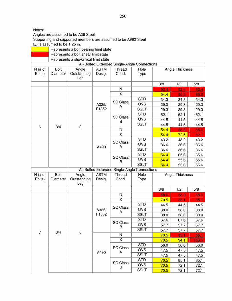
250
Notes: Angles are assumed to be A36 Steel Supporting and supported members are assumed to be A992 Steel Leh is assumed to be 1.25 in. Represents a bolt bearing limit state Represents a bolt shear limit state Represents a slip-critical limit state All-Bolted Extended Single-Angle Connections
N (# of Bolts)
Bolt Diameter
Angle Outstanding
Leg
ASTM Desig.
Thread Cond.
Hole Type
Angle Thickness
3/8 1/2 5/8 N 52.4 52.4 52.4 X 54.4 65.6 65.6 STD 34.3 34.3 34.3 OVS 29.3 29.3 29.3
SC Class A
SSLT 29.3 29.3 29.3 STD 52.1 52.1 52.1 OVS 44.5 44.5 44.5
A325/ F1852
SC Class B
SSLT 44.5 44.5 44.5 N 54.4 65.6 65.6 X 54.4 72.5 82.1 STD 43.2 43.2 43.2 OVS 36.6 36.6 36.6
SC Class A
SSLT 36.6 36.6 36.6 STD 54.4 65.6 65.6 OVS 54.4 55.6 55.6
6 3/4 8
A490
SC Class B
SSLT 54.4 55.6 55.6 All-Bolted Extended Single-Angle Connections
N (# of Bolts)
Bolt Diameter
Angle Outstanding
Leg
ASTM Desig.
Thread Cond.
Hole Type
Angle Thickness
3/8 1/2 5/8 N 68.0 68.0 68.0 X 70.5 85.1 85.1 STD 44.5 44.5 44.5 OVS 38.0 38.0 38.0
SC Class A
SSLT 38.0 38.0 38.0 STD 67.6 67.6 67.6 OVS 57.7 57.7 57.7
A325/ F1852
SC Class B
SSLT 57.7 57.7 57.7 N 70.5 85.1 85.1 X 70.5 94.1 106.5 STD 56.0 56.0 56.0 OVS 47.5 47.5 47.5
SC Class A
SSLT 47.5 47.5 47.5 STD 70.5 85.1 85.1 OVS 70.5 72.1 72.1
7 3/4 8
A490
SC Class B
SSLT 70.5 72.1 72.1

251
Notes: Angles are assumed to be A36 Steel Supporting and supported members are assumed to be A992 Steel Leh is assumed to be 1.25 in. Represents a bolt bearing limit state Represents a bolt shear limit state Represents a slip-critical limit state All-Bolted Extended Single-Angle Connections
N (# of Bolts)
Bolt Diameter
Angle Outstanding
Leg
ASTM Desig.
Thread Cond.
Hole Type
Angle Thickness
3/8 1/2 5/8 N 84.4 84.4 84.4 X 87.6 105.6 105.6 STD 55.2 55.2 55.2 OVS 47.1 47.1 47.1
SC Class A
SSLT 47.1 47.1 47.1 STD 83.9 83.9 83.9 OVS 71.7 71.7 71.7
A325/ F1852
SC Class B
SSLT 71.7 71.7 71.7 N 87.6 105.6 105.6 X 87.6 116.8 132.2 STD 69.5 69.5 69.5 OVS 58.9 58.9 58.9
SC Class A
SSLT 58.9 58.9 58.9 STD 87.6 105.7 105.7 OVS 87.6 89.6 89.6
8 3/4 8
A490
SC Class B
SSLT 87.6 89.6 89.6 All-Bolted Extended Single-Angle Connections
N (# of Bolts)
Bolt Diameter
Angle Outstanding
Leg
ASTM Desig.
Thread Cond.
Hole Type
Angle Thickness
3/8 1/2 5/8 N 101.2 101.2 101.2 X 105.0 126.7 126.7 STD 66.2 66.2 66.2 OVS 56.5 56.5 56.5
SC Class A
SSLT 56.5 56.5 56.5 STD 100.6 100.6 100.6 OVS 85.9 85.9 85.9
A325/ F1852
SC Class B
SSLT 85.9 85.9 85.9 N 105.0 126.7 126.7 X 105.0 140.0 158.5 STD 83.4 83.4 83.4 OVS 70.7 70.7 70.7
SC Class A
SSLT 70.7 70.7 70.7 STD 105.0 126.7 126.7 OVS 105.0 107.4 107.4
9 3/4 8
A490
SC Class B
SSLT 105.0 107.4 107.4

252
Notes: Angles are assumed to be A36 Steel Supporting and supported members are assumed to be A992 Steel Leh is assumed to be 1.25 in. Represents a bolt bearing limit state Represents a bolt shear limit state Represents a slip-critical limit state All-Bolted Extended Single-Angle Connections
N (# of Bolts)
Bolt Diameter
Angle Outstanding
Leg
ASTM Desig.
Thread Cond.
Hole Type
Angle Thickness
3/8 1/2 5/8 N 118.4 118.4 118.4 X 122.9 148.2 148.2 STD 77.5 77.5 77.5 OVS 66.1 66.1 66.1
SC Class A
SSLT 66.1 66.1 66.1 STD 117.7 117.7 117.7 OVS 100.5 100.5 100.5
A325/ F1852
SC Class B
SSLT 100.5 100.5 100.5 N 122.9 148.2 148.2 X 122.9 163.9 185.5 STD 97.6 97.6 97.6 OVS 82.7 82.7 82.7
SC Class A
SSLT 82.7 82.7 82.7 STD 122.9 148.3 148.3 OVS 122.9 125.7 125.7
10 3/4 8
A490
SC Class B
SSLT 122.9 125.7 125.7 All-Bolted Extended Single-Angle Connections
N (# of Bolts)
Bolt Diameter
Angle Outstanding
Leg
ASTM Desig.
Thread Cond.
Hole Type
Angle Thickness
3/8 1/2 5/8 N 135.6 135.6 135.6 X 140.7 169.7 169.7 STD 88.7 88.7 88.7 OVS 75.7 75.7 75.7
SC Class A
SSLT 75.7 75.7 75.7 STD 134.8 134.8 134.8 OVS 115.1 115.1 115.1
A325/ F1852
SC Class B
SSLT 115.1 115.1 115.1 N 140.7 169.7 169.7 X 140.7 187.6 212.4 STD 111.7 111.7 111.7 OVS 94.7 94.7 94.7
SC Class A
SSLT 94.7 94.7 94.7 STD 140.7 169.8 169.8 OVS 140.7 143.9 143.9
11 3/4 8
A490
SC Class B
SSLT 140.7 143.9 143.9

253
Notes: Angles are assumed to be A36 Steel Supporting and supported members are assumed to be A992 Steel Leh is assumed to be 1.25 in. Represents a bolt bearing limit state Represents a bolt shear limit state Represents a slip-critical limit state All-Bolted Extended Single-Angle Connections
N (# of Bolts)
Bolt Diameter
Angle Outstanding
Leg
ASTM Desig.
Thread Cond.
Hole Type
Angle Thickness
3/8 1/2 5/8 N 152.8 152.8 152.8 X 158.6 191.3 191.3 STD 100.0 100.0 100.0 OVS 85.4 85.4 85.4
SC Class A
SSLT 85.4 85.4 85.4 STD 151.9 151.9 151.9 OVS 129.7 129.7 129.7
A325/ F1852
SC Class B
SSLT 129.7 129.7 129.7 N 158.6 191.3 191.3 X 158.6 211.5 239.3 STD 125.9 125.9 125.9 OVS 106.7 106.7 106.7
SC Class A
SSLT 106.7 106.7 106.7 STD 158.6 191.4 191.4 OVS 158.6 162.2 162.2
12 3/4 8
A490
SC Class B
SSLT 158.6 162.2 162.2

254
Notes: Angles are assumed to be A36 Steel Supporting and supported members are assumed to be A992 Steel Leh is assumed to be 1.25 in. Represents a bolt bearing limit state Represents a bolt shear limit state Represents a slip-critical limit state All-Bolted Extended Single-Angle Connections
N (# of Bolts)
Bolt Diameter
Angle Outstanding
Leg
ASTM Desig.
Thread Cond.
Hole Type
Angle Thickness
3/8 1/2 5/8 N 5.2 5.2 5.2 X 5.4 6.5 6.5 STD 3.4 3.4 3.4 OVS 2.9 2.9 2.9
SC Class A
SSLT 2.9 2.9 2.9 STD 5.1 5.1 5.1 OVS 4.4 4.4 4.4
A325/ F1852
SC Class B
SSLT 4.4 4.4 4.4 N 5.4 6.5 6.5 X 5.4 7.2 8.1 STD 4.3 4.3 4.3 OVS 3.6 3.6 3.6
SC Class A
SSLT 3.6 3.6 3.6 STD 5.4 6.5 6.5 OVS 5.4 5.5 5.5
2 3/4 9
A490
SC Class B
SSLT 5.4 5.5 5.5 All-Bolted Extended Single-Angle Connections
N (# of Bolts)
Bolt Diameter
Angle Outstanding
Leg
ASTM Desig.
Thread Cond.
Hole Type
Angle Thickness
3/8 1/2 5/8 N 12.0 12.0 12.0 X 12.5 15.0 15.0 STD 7.9 7.9 7.9 OVS 6.7 6.7 6.7
SC Class A
SSLT 6.7 6.7 6.7 STD 11.9 11.9 11.9 OVS 10.2 10.2 10.2
A325/ F1852
SC Class B
SSLT 10.2 10.2 10.2 N 12.5 15.0 15.0 X 12.5 16.6 18.8 STD 9.9 9.9 9.9 OVS 8.4 8.4 8.4
SC Class A
SSLT 8.4 8.4 8.4 STD 12.5 15.0 15.0 OVS 12.5 12.7 12.7
3 3/4 9
A490
SC Class B
SSLT 12.5 12.7 12.7

255
Notes: Angles are assumed to be A36 Steel Supporting and supported members are assumed to be A992 Steel Leh is assumed to be 1.25 in. Represents a bolt bearing limit state Represents a bolt shear limit state Represents a slip-critical limit state All-Bolted Extended Single-Angle Connections
N (# of Bolts)
Bolt Diameter
Angle Outstanding
Leg
ASTM Desig.
Thread Cond.
Hole Type
Angle Thickness
3/8 1/2 5/8 N 22.0 22.0 22.0 X 22.8 27.5 27.5 STD 14.4 14.4 14.4 OVS 12.3 12.3 12.3
SC Class A
SSLT 12.3 12.3 12.3 STD 21.9 21.9 21.9 OVS 18.7 18.7 18.7
A325/ F1852
SC Class B
SSLT 18.7 18.7 18.7 N 22.8 27.5 27.5 X 22.8 30.4 34.4 STD 18.1 18.1 18.1 OVS 15.3 15.3 15.3
SC Class A
SSLT 15.3 15.3 15.3 STD 22.8 27.5 27.5 OVS 22.8 23.3 23.3
4 3/4 9
A490
SC Class B
SSLT 22.8 23.3 23.3 All-Bolted Extended Single-Angle Connections
N (# of Bolts)
Bolt Diameter
Angle Outstanding
Leg
ASTM Desig.
Thread Cond.
Hole Type
Angle Thickness
3/8 1/2 5/8 N 33.4 33.4 33.4 X 34.7 41.8 41.8 STD 21.8 21.8 21.8 OVS 18.6 18.6 18.6
SC Class A
SSLT 18.6 18.6 18.6 STD 33.2 33.2 33.2 OVS 28.3 28.3 28.3
A325/ F1852
SC Class B
SSLT 28.3 28.3 28.3 N 34.7 41.8 41.8 X 34.7 46.2 52.3 STD 27.5 27.5 27.5 OVS 23.3 23.3 23.3
SC Class A
SSLT 23.3 23.3 23.3 STD 34.7 41.8 41.8 OVS 34.7 35.4 35.4
5 3/4 9
A490
SC Class B
SSLT 34.7 35.4 35.4

256
Notes: Angles are assumed to be A36 Steel Supporting and supported members are assumed to be A992 Steel Leh is assumed to be 1.25 in. Represents a bolt bearing limit state Represents a bolt shear limit state Represents a slip-critical limit state All-Bolted Extended Single-Angle Connections
N (# of Bolts)
Bolt Diameter
Angle Outstanding
Leg
ASTM Desig.
Thread Cond.
Hole Type
Angle Thickness
3/8 1/2 5/8 N 46.6 46.6 46.6 X 48.3 58.3 58.3 STD 30.5 30.5 30.5 OVS 26.0 26.0 26.0
SC Class A
SSLT 26.0 26.0 26.0 STD 46.3 46.3 46.3 OVS 39.5 39.5 39.5
A325/ F1852
SC Class B
SSLT 39.5 39.5 39.5 N 48.3 58.3 58.3 X 48.3 64.5 73.0 STD 38.4 38.4 38.4 OVS 32.5 32.5 32.5
SC Class A
SSLT 32.5 32.5 32.5 STD 48.3 58.3 58.3 OVS 48.3 49.4 49.4
6 3/4 9
A490
SC Class B
SSLT 48.3 49.4 49.4 All-Bolted Extended Single-Angle Connections
N (# of Bolts)
Bolt Diameter
Angle Outstanding
Leg
ASTM Desig.
Thread Cond.
Hole Type
Angle Thickness
3/8 1/2 5/8 N 61.1 61.1 61.1 X 63.4 76.5 76.5 STD 40.0 40.0 40.0 OVS 34.1 34.1 34.1
SC Class A
SSLT 34.1 34.1 34.1 STD 60.8 60.8 60.8 OVS 51.9 51.9 51.9
A325/ F1852
SC Class B
SSLT 51.9 51.9 51.9 N 63.4 76.5 76.5 X 63.4 84.6 95.7 STD 50.4 50.4 50.4 OVS 42.7 42.7 42.7
SC Class A
SSLT 42.7 42.7 42.7 STD 63.4 76.6 76.6 OVS 63.4 64.9 64.9
7 3/4 9
A490
SC Class B
SSLT 63.4 64.9 64.9

257
Notes: Angles are assumed to be A36 Steel Supporting and supported members are assumed to be A992 Steel Leh is assumed to be 1.25 in. Represents a bolt bearing limit state Represents a bolt shear limit state Represents a slip-critical limit state All-Bolted Extended Single-Angle Connections
N (# of Bolts)
Bolt Diameter
Angle Outstanding
Leg
ASTM Desig.
Thread Cond.
Hole Type
Angle Thickness
3/8 1/2 5/8 N 76.8 76.8 76.8 X 79.7 96.1 96.1 STD 50.2 50.2 50.2 OVS 42.9 42.9 42.9
SC Class A
SSLT 42.9 42.9 42.9 STD 76.3 76.3 76.3 OVS 65.2 65.2 65.2
A325/ F1852
SC Class B
SSLT 65.2 65.2 65.2 N 79.7 96.1 96.1 X 79.7 106.2 120.2 STD 63.2 63.2 63.2 OVS 53.6 53.6 53.6
SC Class A
SSLT 53.6 53.6 53.6 STD 79.7 96.1 96.1 OVS 79.7 81.4 81.4
8 3/4 9
A490
SC Class B
SSLT 79.7 81.4 81.4 All-Bolted Extended Single-Angle Connections
N (# of Bolts)
Bolt Diameter
Angle Outstanding
Leg
ASTM Desig.
Thread Cond.
Hole Type
Angle Thickness
3/8 1/2 5/8 N 93.0 93.0 93.0 X 96.5 116.4 116.4 STD 60.8 60.8 60.8 OVS 51.9 51.9 51.9
SC Class A
SSLT 51.9 51.9 51.9 STD 92.4 92.4 92.4 OVS 78.9 78.9 78.9
A325/ F1852
SC Class B
SSLT 78.9 78.9 78.9 N 96.5 116.4 116.4 X 96.5 128.6 145.6 STD 76.6 76.6 76.6 OVS 64.9 64.9 64.9
SC Class A
SSLT 64.9 64.9 64.9 STD 96.5 116.4 116.4 OVS 96.5 98.7 98.7
9 3/4 9
A490
SC Class B
SSLT 96.5 98.7 98.7

258
Notes: Angles are assumed to be A36 Steel Supporting and supported members are assumed to be A992 Steel Leh is assumed to be 1.25 in. Represents a bolt bearing limit state Represents a bolt shear limit state Represents a slip-critical limit state All-Bolted Extended Single-Angle Connections
N (# of Bolts)
Bolt Diameter
Angle Outstanding
Leg
ASTM Desig.
Thread Cond.
Hole Type
Angle Thickness
3/8 1/2 5/8 N 109.8 109.8 109.8 X 113.9 137.4 137.4 STD 71.8 71.8 71.8 OVS 61.3 61.3 61.3
SC Class A
SSLT 61.3 61.3 61.3 STD 109.2 109.2 109.2 OVS 93.2 93.2 93.2
A325/ F1852
SC Class B
SSLT 93.2 93.2 93.2 N 113.9 137.4 137.4 X 113.9 151.9 171.9 STD 90.5 90.5 90.5 OVS 76.6 76.6 76.6
SC Class A
SSLT 76.6 76.6 76.6 STD 113.9 137.5 137.5 OVS 113.9 116.5 116.5
10 3/4 9
A490
SC Class B
SSLT 113.9 116.5 116.5 All-Bolted Extended Single-Angle Connections
N (# of Bolts)
Bolt Diameter
Angle Outstanding
Leg
ASTM Desig.
Thread Cond.
Hole Type
Angle Thickness
3/8 1/2 5/8 N 126.8 126.8 126.8 X 131.6 158.8 158.8 STD 83.0 83.0 83.0 OVS 70.8 70.8 70.8
SC Class A
SSLT 70.8 70.8 70.8 STD 126.1 126.1 126.1 OVS 107.7 107.7 107.7
A325/ F1852
SC Class B
SSLT 107.7 107.7 107.7 N 131.6 158.8 158.8 X 131.6 175.5 198.6 STD 104.5 104.5 104.5 OVS 88.6 88.6 88.6
SC Class A
SSLT 88.6 88.6 88.6 STD 131.6 158.8 158.8 OVS 131.6 134.6 134.6
11 3/4 9
A490
SC Class B
SSLT 131.6 134.6 134.6
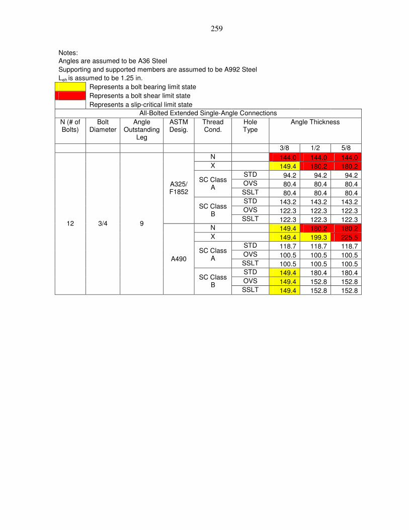
259
Notes: Angles are assumed to be A36 Steel Supporting and supported members are assumed to be A992 Steel Leh is assumed to be 1.25 in. Represents a bolt bearing limit state Represents a bolt shear limit state Represents a slip-critical limit state All-Bolted Extended Single-Angle Connections
N (# of Bolts)
Bolt Diameter
Angle Outstanding
Leg
ASTM Desig.
Thread Cond.
Hole Type
Angle Thickness
3/8 1/2 5/8 N 144.0 144.0 144.0 X 149.4 180.2 180.2 STD 94.2 94.2 94.2 OVS 80.4 80.4 80.4
SC Class A
SSLT 80.4 80.4 80.4 STD 143.2 143.2 143.2 OVS 122.3 122.3 122.3
A325/ F1852
SC Class B
SSLT 122.3 122.3 122.3 N 149.4 180.2 180.2 X 149.4 199.3 225.5 STD 118.7 118.7 118.7 OVS 100.5 100.5 100.5
SC Class A
SSLT 100.5 100.5 100.5 STD 149.4 180.4 180.4 OVS 149.4 152.8 152.8
12 3/4 9
A490
SC Class B
SSLT 149.4 152.8 152.8

260
APPENDIX H 7/8-INCH DIAMETER ALL-BOLTED A36 STEEL SINGLE ANGLE
CONNECTIONS
The tables given in Appendix H are all-bolted single angle connections. The angles
are A36 angles using either A325/F1852 or A490 7/8-inch diameter bolts.

261
Notes: Angles are assumed to be A36 Steel Supporting and supported members are assumed to be A992 Steel Leh is assumed to be 1.25 in. Represents a bolt bearing limit state Represents a bolt shear limit state Represents a slip-critical limit state All-Bolted Extended Single-Angle Connections
N (# of Bolts)
Bolt Diameter
Angle Outstanding
Leg
ASTM Desig.
Thread Cond.
Hole Type
Angle Thickness
3/8 1/2 5/8 N 8.3 11.1 13.8 X 8.3 11.1 13.8 STD 7.9 7.9 7.9 OVS 6.7 6.7 6.7
SC Class A
SSLT 6.7 6.7 6.7 STD 8.3 11.1 12.0 OVS 7.6 10.2 10.2
A325/ F1852
SC Class B
SSLT 8.3 10.2 10.2 N 8.3 11.1 13.8 X 8.3 11.1 13.8 STD 8.3 9.9 9.9 OVS 7.6 8.4 8.4
SC Class A
SSLT 8.3 8.4 8.4 STD 8.3 11.1 13.8 OVS 7.6 10.2 12.7
2 7/8 6
A490
SC Class B
SSLT 8.3 11.1 12.8 All-Bolted Extended Single-Angle Connections
N (# of Bolts)
Bolt Diameter
Angle Outstanding
Leg
ASTM Desig.
Thread Cond.
Hole Type
Angle Thickness
3/8 1/2 5/8 N 18.6 24.7 30.9 X 18.6 24.7 30.9 STD 17.6 17.6 17.6 OVS 15.0 15.0 15.0
SC Class A
SSLT 15.0 15.0 15.0 STD 18.6 24.7 26.7 OVS 17.1 22.7 22.9
A325/ F1852
SC Class B
SSLT 18.6 22.9 22.9 N 18.6 24.7 30.9 X 18.6 24.7 30.9 STD 18.6 22.2 22.2 OVS 17.1 18.8 18.8
SC Class A
SSLT 18.6 18.8 18.8 STD 18.6 24.7 30.9 OVS 17.1 22.7 28.4
3 7/8 6
A490
SC Class B
SSLT 18.6 24.7 28.6

262
Notes: Angles are assumed to be A36 Steel Supporting and supported members are assumed to be A992 Steel Leh is assumed to be 1.25 in. Represents a bolt bearing limit state Represents a bolt shear limit state Represents a slip-critical limit state All-Bolted Extended Single-Angle Connections
N (# of Bolts)
Bolt Diameter
Angle Outstanding
Leg
ASTM Desig.
Thread Cond.
Hole Type
Angle Thickness
3/8 1/2 5/8 N 32.1 42.8 53.5 X 32.1 42.8 53.5 STD 30.4 30.4 30.4 OVS 26.0 26.0 26.0
SC Class A
SSLT 26.0 26.0 26.0 STD 32.1 42.8 46.2 OVS 29.5 39.3 39.5
A325/ F1852
SC Class B
SSLT 32.1 39.5 39.5 N 32.1 42.8 53.5 X 32.1 42.8 53.5 STD 32.1 38.4 38.4 OVS 29.5 32.5 32.5
SC Class A
SSLT 32.1 32.5 32.5 STD 32.1 42.8 53.5 OVS 29.5 39.3 49.2
4 7/8 6
A490
SC Class B
SSLT 32.1 42.8 49.4 All-Bolted Extended Single-Angle Connections
N (# of Bolts)
Bolt Diameter
Angle Outstanding
Leg
ASTM Desig.
Thread Cond.
Hole Type
Angle Thickness
3/8 1/2 5/8 N 47.0 62.6 78.3 X 47.0 62.6 78.3 STD 44.5 44.5 44.5 OVS 38.1 38.1 38.1
SC Class A
SSLT 38.1 38.1 38.1 STD 47.0 62.6 67.7 OVS 43.2 57.6 57.9
A325/ F1852
SC Class B
SSLT 47.0 57.9 57.9 N 47.0 62.6 78.3 X 47.0 62.6 78.3 STD 47.0 56.2 56.2 OVS 43.2 47.6 47.6
SC Class A
SSLT 47.0 47.6 47.6 STD 47.0 62.6 78.3 OVS 43.2 57.6 72.0
5 7/8 6
A490
SC Class B
SSLT 47.0 62.6 72.3

263
Notes: Angles are assumed to be A36 Steel Supporting and supported members are assumed to be A992 Steel Leh is assumed to be 1.25 in. Represents a bolt bearing limit state Represents a bolt shear limit state Represents a slip-critical limit state All-Bolted Extended Single-Angle Connections
N (# of Bolts)
Bolt Diameter
Angle Outstanding
Leg
ASTM Desig.
Thread Cond.
Hole Type
Angle Thickness
3/8 1/2 5/8 N 62.8 83.7 104.6 X 62.8 83.7 104.6 STD 59.5 59.5 59.5 OVS 50.9 50.9 50.9
SC Class A
SSLT 50.9 50.9 50.9 STD 62.8 83.7 90.4 OVS 57.7 76.9 77.3
A325/ F1852
SC Class B
SSLT 62.8 77.3 77.3 N 62.8 83.7 104.6 X 62.8 83.7 104.6 STD 62.8 75.1 75.1 OVS 57.7 63.6 63.6
SC Class A
SSLT 62.8 63.6 63.6 STD 62.8 83.7 104.6 OVS 57.7 76.9 96.2
6 7/8 6
A490
SC Class B
SSLT 62.8 83.7 96.7 All-Bolted Extended Single-Angle Connections
N (# of Bolts)
Bolt Diameter
Angle Outstanding
Leg
ASTM Desig.
Thread Cond.
Hole Type
Angle Thickness
3/8 1/2 5/8 N 79.3 105.8 132.2 X 79.3 105.8 132.2 STD 75.2 75.2 75.2 OVS 64.3 64.3 64.3
SC Class A
SSLT 64.3 64.3 64.3 STD 79.3 105.8 114.3 OVS 72.9 97.2 97.7
A325/ F1852
SC Class B
SSLT 79.3 97.7 97.7 N 79.3 105.8 132.2 X 79.3 105.8 132.2 STD 79.3 94.9 94.9 OVS 72.9 80.4 80.4
SC Class A
SSLT 79.3 80.4 80.4 STD 79.3 105.8 132.2 OVS 72.9 97.2 121.5
7 7/8 6
A490
SC Class B
SSLT 79.3 105.8 122.2

264
Notes: Angles are assumed to be A36 Steel Supporting and supported members are assumed to be A992 Steel Leh is assumed to be 1.25 in. Represents a bolt bearing limit state Represents a bolt shear limit state Represents a slip-critical limit state All-Bolted Extended Single-Angle Connections
N (# of Bolts)
Bolt Diameter
Angle Outstanding
Leg
ASTM Desig.
Thread Cond.
Hole Type
Angle Thickness
3/8 1/2 5/8 N 95.7 127.7 159.6 X 95.7 127.7 159.6 STD 90.7 90.7 90.7 OVS 77.6 77.6 77.6
SC Class A
SSLT 77.6 77.6 77.6 STD 95.7 127.7 137.9 OVS 88.0 117.3 117.9
A325/ F1852
SC Class B
SSLT 95.7 117.9 117.9 N 95.7 127.7 159.6 X 95.7 127.7 159.6 STD 95.7 114.5 114.5 OVS 88.0 97.0 97.0
SC Class A
SSLT 95.7 97.0 97.0 STD 95.7 127.7 159.6 OVS 88.0 117.3 146.7
8 7/8 6
A490
SC Class B
SSLT 95.7 127.7 147.4 All-Bolted Extended Single-Angle Connections
N (# of Bolts)
Bolt Diameter
Angle Outstanding
Leg
ASTM Desig.
Thread Cond.
Hole Type
Angle Thickness
3/8 1/2 5/8 N 112.4 149.8 187.3 X 112.4 149.8 187.3 STD 106.5 106.5 106.5 OVS 91.1 91.1 91.1
SC Class A
SSLT 91.1 91.1 91.1 STD 112.4 149.8 161.9 OVS 103.3 137.7 138.4
A325/ F1852
SC Class B
SSLT 112.4 138.4 138.4 N 112.4 149.8 187.3 X 112.4 149.8 187.3 STD 112.4 134.4 134.4 OVS 103.3 113.8 113.8
SC Class A
SSLT 112.4 113.8 113.8 STD 112.4 149.8 187.3 OVS 103.3 137.7 172.1
9 7/8 6
A490
SC Class B
SSLT 112.4 149.8 173.0

265
Notes: Angles are assumed to be A36 Steel Supporting and supported members are assumed to be A992 Steel Leh is assumed to be 1.25 in. Represents a bolt bearing limit state Represents a bolt shear limit state Represents a slip-critical limit state All-Bolted Extended Single-Angle Connections
N (# of Bolts)
Bolt Diameter
Angle Outstanding
Leg
ASTM Desig.
Thread Cond.
Hole Type
Angle Thickness
3/8 1/2 5/8 N 128.8 171.8 214.7 X 128.8 171.8 214.7 STD 122.1 122.1 122.1 OVS 104.4 104.4 104.4
SC Class A
SSLT 104.4 104.4 104.4 STD 128.8 171.8 185.6 OVS 118.4 157.9 158.7
A325/ F1852
SC Class B
SSLT 128.8 158.7 158.7 N 128.8 171.8 214.7 X 128.8 171.8 214.7 STD 128.8 154.1 154.1 OVS 118.4 130.5 130.5
SC Class A
SSLT 128.8 130.5 130.5 STD 128.8 171.8 214.7 OVS 118.4 157.9 197.3
10 7/8 6
A490
SC Class B
SSLT 128.8 171.8 198.4 All-Bolted Extended Single-Angle Connections
N (# of Bolts)
Bolt Diameter
Angle Outstanding
Leg
ASTM Desig.
Thread Cond.
Hole Type
Angle Thickness
3/8 1/2 5/8 N 145.3 193.7 242.1 X 145.3 193.7 242.1 STD 137.7 137.7 137.7 OVS 117.7 117.7 117.7
SC Class A
SSLT 117.7 117.7 117.7 STD 145.3 193.7 209.3 OVS 133.5 178.0 179.0
A325/ F1852
SC Class B
SSLT 145.3 179.0 179.0 N 145.3 193.7 242.1 X 145.3 193.7 242.1 STD 145.3 173.8 173.8 OVS 133.5 147.2 147.2
SC Class A
SSLT 145.3 147.2 147.2 STD 145.3 193.7 242.1 OVS 133.5 178.0 222.5
11 7/8 6
A490
SC Class B
SSLT 145.3 193.7 223.7

266
Notes: Angles are assumed to be A36 Steel Supporting and supported members are assumed to be A992 Steel Leh is assumed to be 1.25 in. Represents a bolt bearing limit state Represents a bolt shear limit state Represents a slip-critical limit state All-Bolted Extended Single-Angle Connections
N (# of Bolts)
Bolt Diameter
Angle Outstanding
Leg
ASTM Desig.
Thread Cond.
Hole Type
Angle Thickness
3/8 1/2 5/8 N 161.0 214.7 268.4 X 161.0 214.7 268.4 STD 152.6 152.6 152.6 OVS 130.5 130.5 130.5
SC Class A
SSLT 130.5 130.5 130.5 STD 161.0 214.7 232.0 OVS 148.0 197.3 198.4
A325/ F1852
SC Class B
SSLT 161.0 198.4 198.4 N 161.0 214.7 268.4 X 161.0 214.7 268.4 STD 161.0 192.6 192.6 OVS 148.0 163.1 163.1
SC Class A
SSLT 161.0 163.1 163.1 STD 161.0 214.7 268.4 OVS 148.0 197.3 246.7
12 7/8 6
A490
SC Class B
SSLT 161.0 214.7 248.0

267
Notes: Angles are assumed to be A36 Steel Supporting and supported members are assumed to be A992 Steel Leh is assumed to be 1.25 in. Represents a bolt bearing limit state Represents a bolt shear limit state Represents a slip-critical limit state All-Bolted Extended Single-Angle Connections
N (# of Bolts)
Bolt Diameter
Angle Outstanding
Leg
ASTM Desig.
Thread Cond.
Hole Type
Angle Thickness
3/8 1/2 5/8 N 7.7 10.2 12.8 X 7.7 10.2 12.8 STD 7.3 7.3 7.3 OVS 6.2 6.2 6.2
SC Class A
SSLT 6.2 6.2 6.2 STD 7.7 10.2 11.0 OVS 7.0 9.4 9.4
A325/ F1852
SC Class B
SSLT 7.7 9.4 9.4 N 7.7 10.2 12.8 X 7.7 10.2 12.8 STD 7.7 9.2 9.2 OVS 7.0 7.8 7.8
SC Class A
SSLT 7.7 7.8 7.8 STD 7.7 10.2 12.8 OVS 7.0 9.4 11.7
2 7/8 7
A490
SC Class B
SSLT 7.7 10.2 11.8 All-Bolted Extended Single-Angle Connections
N (# of Bolts)
Bolt Diameter
Angle Outstanding
Leg
ASTM Desig.
Thread Cond.
Hole Type
Angle Thickness
3/8 1/2 5/8 N 15.5 20.7 25.9 X 15.5 20.7 25.9 STD 14.7 14.7 14.7 OVS 12.6 12.6 12.6
SC Class A
SSLT 12.6 12.6 12.6 STD 15.5 20.7 22.4 OVS 14.3 19.0 19.1
A325/ F1852
SC Class B
SSLT 15.5 19.1 19.1 N 15.5 20.7 25.9 X 15.5 20.7 25.9 STD 15.5 18.6 18.6 OVS 14.3 15.7 15.7
SC Class A
SSLT 15.5 15.7 15.7 STD 15.5 20.7 25.9 OVS 14.3 19.0 23.8
3 7/8 7
A490
SC Class B
SSLT 15.5 20.7 23.9

268
Notes: Angles are assumed to be A36 Steel Supporting and supported members are assumed to be A992 Steel Leh is assumed to be 1.25 in. Represents a bolt bearing limit state Represents a bolt shear limit state Represents a slip-critical limit state All-Bolted Extended Single-Angle Connections
N (# of Bolts)
Bolt Diameter
Angle Outstanding
Leg
ASTM Desig.
Thread Cond.
Hole Type
Angle Thickness
3/8 1/2 5/8 N 27.9 37.2 46.5 X 27.9 37.2 46.5 STD 26.4 26.4 26.4 OVS 22.6 22.6 22.6
SC Class A
SSLT 22.6 22.6 22.6 STD 27.9 37.2 40.2 OVS 25.6 34.2 34.4
A325/ F1852
SC Class B
SSLT 27.9 34.4 34.4 N 27.9 37.2 46.5 X 27.9 37.2 46.5 STD 27.9 33.4 33.4 OVS 25.6 28.2 28.2
SC Class A
SSLT 27.9 28.2 28.2 STD 27.9 37.2 46.5 OVS 25.6 34.2 42.7
4 7/8 7
A490
SC Class B
SSLT 27.9 37.2 42.9 All-Bolted Extended Single-Angle Connections
N (# of Bolts)
Bolt Diameter
Angle Outstanding
Leg
ASTM Desig.
Thread Cond.
Hole Type
Angle Thickness
3/8 1/2 5/8 N 41.0 54.7 68.4 X 41.0 54.7 68.4 STD 38.9 38.9 38.9 OVS 33.3 33.3 33.3
SC Class A
SSLT 33.3 33.3 33.3 STD 41.0 54.7 59.1 OVS 37.7 50.3 50.6
A325/ F1852
SC Class B
SSLT 41.0 50.6 50.6 N 41.0 54.7 68.4 X 41.0 54.7 68.4 STD 41.0 49.1 49.1 OVS 37.7 41.6 41.6
SC Class A
SSLT 41.0 41.6 41.6 STD 41.0 54.7 68.4 OVS 37.7 50.3 62.9
5 7/8 7
A490
SC Class B
SSLT 41.0 54.7 63.2

269
Notes: Angles are assumed to be A36 Steel Supporting and supported members are assumed to be A992 Steel Leh is assumed to be 1.25 in. Represents a bolt bearing limit state Represents a bolt shear limit state Represents a slip-critical limit state All-Bolted Extended Single-Angle Connections
N (# of Bolts)
Bolt Diameter
Angle Outstanding
Leg
ASTM Desig.
Thread Cond.
Hole Type
Angle Thickness
3/8 1/2 5/8 N 56.0 74.6 93.3 X 56.0 74.6 93.3 STD 53.0 53.0 53.0 OVS 45.4 45.4 45.4
SC Class A
SSLT 45.4 45.4 45.4 STD 56.0 74.6 80.6 OVS 51.4 68.6 68.9
A325/ F1852
SC Class B
SSLT 56.0 68.9 68.9 N 56.0 74.6 93.3 X 56.0 74.6 93.3 STD 56.0 66.9 66.9 OVS 51.4 56.7 56.7
SC Class A
SSLT 56.0 56.7 56.7 STD 56.0 74.6 93.3 OVS 51.4 68.6 85.7
6 7/8 7
A490
SC Class B
SSLT 56.0 74.6 86.2 All-Bolted Extended Single-Angle Connections
N (# of Bolts)
Bolt Diameter
Angle Outstanding
Leg
ASTM Desig.
Thread Cond.
Hole Type
Angle Thickness
3/8 1/2 5/8 N 71.8 95.7 119.6 X 71.8 95.7 119.6 STD 68.0 68.0 68.0 OVS 58.2 58.2 58.2
SC Class A
SSLT 58.2 58.2 58.2 STD 71.8 95.7 103.4 OVS 66.0 87.9 88.4
A325/ F1852
SC Class B
SSLT 71.8 88.4 88.4 N 71.8 95.7 119.6 X 71.8 95.7 119.6 STD 71.8 85.8 85.8 OVS 66.0 72.7 72.7
SC Class A
SSLT 71.8 72.7 72.7 STD 71.8 95.7 119.6 OVS 66.0 87.9 109.9
7 7/8 7
A490
SC Class B
SSLT 71.8 95.7 110.5

270
Notes: Angles are assumed to be A36 Steel Supporting and supported members are assumed to be A992 Steel Leh is assumed to be 1.25 in. Represents a bolt bearing limit state Represents a bolt shear limit state Represents a slip-critical limit state All-Bolted Extended Single-Angle Connections
N (# of Bolts)
Bolt Diameter
Angle Outstanding
Leg
ASTM Desig.
Thread Cond.
Hole Type
Angle Thickness
3/8 1/2 5/8 N 88.1 117.4 146.8 X 88.1 117.4 146.8 STD 83.4 83.4 83.4 OVS 71.4 71.4 71.4
SC Class A
SSLT 71.4 71.4 71.4 STD 88.1 117.4 126.8 OVS 80.9 107.9 108.5
A325/ F1852
SC Class B
SSLT 88.1 108.5 108.5 N 88.1 117.4 146.8 X 88.1 117.4 146.8 STD 88.1 105.3 105.3 OVS 80.9 89.2 89.2
SC Class A
SSLT 88.1 89.2 89.2 STD 88.1 117.4 146.8 OVS 80.9 107.9 134.9
8 7/8 7
A490
SC Class B
SSLT 88.1 117.4 135.6 All-Bolted Extended Single-Angle Connections
N (# of Bolts)
Bolt Diameter
Angle Outstanding
Leg
ASTM Desig.
Thread Cond.
Hole Type
Angle Thickness
3/8 1/2 5/8 N 104.5 139.3 174.2 X 104.5 139.3 174.2 STD 99.0 99.0 99.0 OVS 84.7 84.7 84.7
SC Class A
SSLT 84.7 84.7 84.7 STD 104.5 139.3 150.5 OVS 96.0 128.1 128.7
A325/ F1852
SC Class B
SSLT 104.5 128.7 128.7 N 104.5 139.3 174.2 X 104.5 139.3 174.2 STD 104.5 125.0 125.0 OVS 96.0 105.9 105.9
SC Class A
SSLT 104.5 105.9 105.9 STD 104.5 139.3 174.2 OVS 96.0 128.1 160.1
9 7/8 7
A490
SC Class B
SSLT 104.5 139.3 160.9

271
Notes: Angles are assumed to be A36 Steel Supporting and supported members are assumed to be A992 Steel Leh is assumed to be 1.25 in. Represents a bolt bearing limit state Represents a bolt shear limit state Represents a slip-critical limit state All-Bolted Extended Single-Angle Connections
N (# of Bolts)
Bolt Diameter
Angle Outstanding
Leg
ASTM Desig.
Thread Cond.
Hole Type
Angle Thickness
3/8 1/2 5/8 N 121.1 161.5 201.9 X 121.1 161.5 201.9 STD 114.8 114.8 114.8 OVS 98.2 98.2 98.2
SC Class A
SSLT 98.2 98.2 98.2 STD 121.1 161.5 174.5 OVS 111.3 148.5 149.2
A325/ F1852
SC Class B
SSLT 121.1 149.2 149.2 N 121.1 161.5 201.9 X 121.1 161.5 201.9 STD 121.1 144.9 144.9 OVS 111.3 122.7 122.7
SC Class A
SSLT 121.1 122.7 122.7 STD 121.1 161.5 201.9 OVS 111.3 148.5 185.6
10 7/8 7
A490
SC Class B
SSLT 121.1 161.5 186.5 All-Bolted Extended Single-Angle Connections
N (# of Bolts)
Bolt Diameter
Angle Outstanding
Leg
ASTM Desig.
Thread Cond.
Hole Type
Angle Thickness
3/8 1/2 5/8 N 138.8 185.1 231.3 X 138.8 185.1 231.3 STD 131.6 131.6 131.6 OVS 112.5 112.5 112.5
SC Class A
SSLT 112.5 112.5 112.5 STD 138.8 185.1 200.0 OVS 127.6 170.1 171.0
A325/ F1852
SC Class B
SSLT 138.8 171.0 171.0 N 138.8 185.1 231.3 X 138.8 185.1 231.3 STD 138.8 166.0 166.0 OVS 127.6 140.6 140.6
SC Class A
SSLT 138.8 140.6 140.6 STD 138.8 185.1 231.3 OVS 127.6 170.1 212.6
11 7/8 7
A490
SC Class B
SSLT 138.8 185.1 213.7

272
Notes: Angles are assumed to be A36 Steel Supporting and supported members are assumed to be A992 Steel Leh is assumed to be 1.25 in. Represents a bolt bearing limit state Represents a bolt shear limit state Represents a slip-critical limit state All-Bolted Extended Single-Angle Connections
N (# of Bolts)
Bolt Diameter
Angle Outstanding
Leg
ASTM Desig.
Thread Cond.
Hole Type
Angle Thickness
3/8 1/2 5/8 N 154.1 205.4 256.8 X 154.1 205.4 256.8 STD 146.0 146.0 146.0 OVS 124.9 124.9 124.9
SC Class A
SSLT 124.9 124.9 124.9 STD 154.1 205.4 221.9 OVS 141.6 188.8 189.8
A325/ F1852
SC Class B
SSLT 154.1 189.8 189.8 N 154.1 205.4 256.8 X 154.1 205.4 256.8 STD 154.1 184.3 184.3 OVS 141.6 156.1 156.1
SC Class A
SSLT 154.1 156.1 156.1 STD 154.1 205.4 256.8 OVS 141.6 188.8 236.0
12 7/8 7
A490
SC Class B
SSLT 154.1 205.4 237.2

273
Notes: Angles are assumed to be A36 Steel Supporting and supported members are assumed to be A992 Steel Leh is assumed to be 1.25 in. Represents a bolt bearing limit state Represents a bolt shear limit state Represents a slip-critical limit state All-Bolted Extended Single-Angle Connections
N (# of Bolts)
Bolt Diameter
Angle Outstanding
Leg
ASTM Desig.
Thread Cond.
Hole Type
Angle Thickness
3/8 1/2 5/8 N 6.6 8.8 11.0 X 6.6 8.8 11.0 STD 6.3 6.3 6.3 OVS 5.4 5.4 5.4
SC Class A
SSLT 5.4 5.4 5.4 STD 6.6 8.8 9.5 OVS 6.1 8.1 8.2
A325/ F1852
SC Class B
SSLT 6.6 8.2 8.2 N 6.6 8.8 11.0 X 6.6 8.8 11.0 STD 6.6 7.9 7.9 OVS 6.1 6.7 6.7
SC Class A
SSLT 6.6 6.7 6.7 STD 6.6 8.8 11.0 OVS 6.1 8.1 10.2
2 7/8 8
A490
SC Class B
SSLT 6.6 8.8 10.2 All-Bolted Extended Single-Angle Connections
N (# of Bolts)
Bolt Diameter
Angle Outstanding
Leg
ASTM Desig.
Thread Cond.
Hole Type
Angle Thickness
3/8 1/2 5/8 N 13.4 17.9 22.3 X 13.4 17.9 22.3 STD 12.7 12.7 12.7 OVS 10.9 10.9 10.9
SC Class A
SSLT 10.9 10.9 10.9 STD 13.4 17.9 19.3 OVS 12.3 16.4 16.5
A325/ F1852
SC Class B
SSLT 13.4 16.5 16.5 N 13.4 17.9 22.3 X 13.4 17.9 22.3 STD 13.4 16.0 16.0 OVS 12.3 13.6 13.6
SC Class A
SSLT 13.4 13.6 13.6 STD 13.4 17.9 22.3 OVS 12.3 16.4 20.5
3 7/8 8
A490
SC Class B
SSLT 13.4 17.9 20.6

274
Notes: Angles are assumed to be A36 Steel Supporting and supported members are assumed to be A992 Steel Leh is assumed to be 1.25 in. Represents a bolt bearing limit state Represents a bolt shear limit state Represents a slip-critical limit state All-Bolted Extended Single-Angle Connections
N (# of Bolts)
Bolt Diameter
Angle Outstanding
Leg
ASTM Desig.
Thread Cond.
Hole Type
Angle Thickness
3/8 1/2 5/8 N 24.2 32.3 40.4 X 24.2 32.3 40.4 STD 22.9 22.9 22.9 OVS 19.6 19.6 19.6
SC Class A
SSLT 19.6 19.6 19.6 STD 24.2 32.3 34.9 OVS 22.3 29.7 29.8
A325/ F1852
SC Class B
SSLT 24.2 29.8 29.8 N 24.2 32.3 40.4 X 24.2 32.3 40.4 STD 24.2 29.0 29.0 OVS 22.3 24.5 24.5
SC Class A
SSLT 24.2 24.5 24.5 STD 24.2 32.3 40.4 OVS 22.3 29.7 37.1
4 7/8 8
A490
SC Class B
SSLT 24.2 32.3 37.3 All-Bolted Extended Single-Angle Connections
N (# of Bolts)
Bolt Diameter
Angle Outstanding
Leg
ASTM Desig.
Thread Cond.
Hole Type
Angle Thickness
3/8 1/2 5/8 N 36.4 48.6 60.7 X 36.4 48.6 60.7 STD 34.5 34.5 34.5 OVS 29.5 29.5 29.5
SC Class A
SSLT 29.5 29.5 29.5 STD 36.4 48.6 52.5 OVS 33.5 44.7 44.9
A325/ F1852
SC Class B
SSLT 36.4 44.9 44.9 N 36.4 48.6 60.7 X 36.4 48.6 60.7 STD 36.4 43.6 43.6 OVS 33.5 36.9 36.9
SC Class A
SSLT 36.4 36.9 36.9 STD 36.4 48.6 60.7 OVS 33.5 44.7 55.8
5 7/8 8
A490
SC Class B
SSLT 36.4 48.6 56.1
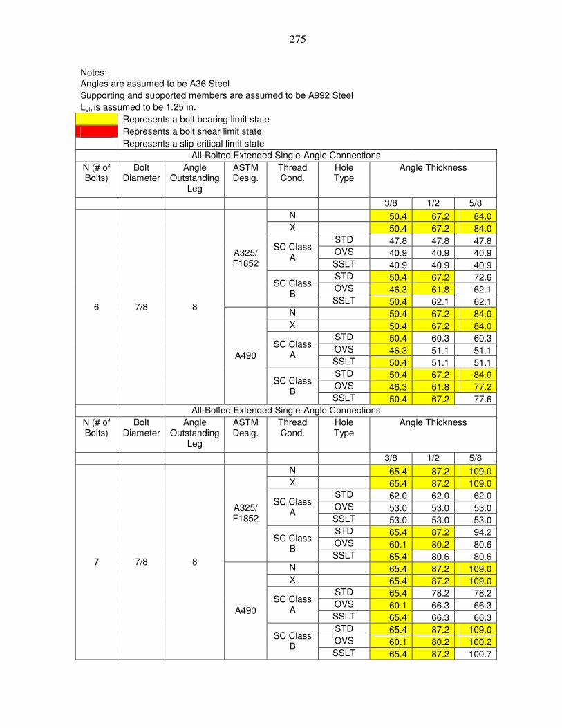
275
Notes: Angles are assumed to be A36 Steel Supporting and supported members are assumed to be A992 Steel Leh is assumed to be 1.25 in. Represents a bolt bearing limit state Represents a bolt shear limit state Represents a slip-critical limit state All-Bolted Extended Single-Angle Connections
N (# of Bolts)
Bolt Diameter
Angle Outstanding
Leg
ASTM Desig.
Thread Cond.
Hole Type
Angle Thickness
3/8 1/2 5/8 N 50.4 67.2 84.0 X 50.4 67.2 84.0 STD 47.8 47.8 47.8 OVS 40.9 40.9 40.9
SC Class A
SSLT 40.9 40.9 40.9 STD 50.4 67.2 72.6 OVS 46.3 61.8 62.1
A325/ F1852
SC Class B
SSLT 50.4 62.1 62.1 N 50.4 67.2 84.0 X 50.4 67.2 84.0 STD 50.4 60.3 60.3 OVS 46.3 51.1 51.1
SC Class A
SSLT 50.4 51.1 51.1 STD 50.4 67.2 84.0 OVS 46.3 61.8 77.2
6 7/8 8
A490
SC Class B
SSLT 50.4 67.2 77.6 All-Bolted Extended Single-Angle Connections
N (# of Bolts)
Bolt Diameter
Angle Outstanding
Leg
ASTM Desig.
Thread Cond.
Hole Type
Angle Thickness
3/8 1/2 5/8 N 65.4 87.2 109.0 X 65.4 87.2 109.0 STD 62.0 62.0 62.0 OVS 53.0 53.0 53.0
SC Class A
SSLT 53.0 53.0 53.0 STD 65.4 87.2 94.2 OVS 60.1 80.2 80.6
A325/ F1852
SC Class B
SSLT 65.4 80.6 80.6 N 65.4 87.2 109.0 X 65.4 87.2 109.0 STD 65.4 78.2 78.2 OVS 60.1 66.3 66.3
SC Class A
SSLT 65.4 66.3 66.3 STD 65.4 87.2 109.0 OVS 60.1 80.2 100.2
7 7/8 8
A490
SC Class B
SSLT 65.4 87.2 100.7

276
Notes: Angles are assumed to be A36 Steel Supporting and supported members are assumed to be A992 Steel Leh is assumed to be 1.25 in. Represents a bolt bearing limit state Represents a bolt shear limit state Represents a slip-critical limit state All-Bolted Extended Single-Angle Connections
N (# of Bolts)
Bolt Diameter
Angle Outstanding
Leg
ASTM Desig.
Thread Cond.
Hole Type
Angle Thickness
3/8 1/2 5/8 N 81.2 108.3 135.4 X 81.2 108.3 135.4 STD 77.0 77.0 77.0 OVS 65.8 65.8 65.8
SC Class A
SSLT 65.8 65.8 65.8 STD 81.2 108.3 117.0 OVS 74.6 99.5 100.1
A325/ F1852
SC Class B
SSLT 81.2 100.1 100.1 N 81.2 108.3 135.4 X 81.2 108.3 135.4 STD 81.2 97.1 97.1 OVS 74.6 82.3 82.3
SC Class A
SSLT 81.2 82.3 82.3 STD 81.2 108.3 135.4 OVS 74.6 99.5 124.4
8 7/8 8
A490
SC Class B
SSLT 81.2 108.3 125.1 All-Bolted Extended Single-Angle Connections
N (# of Bolts)
Bolt Diameter
Angle Outstanding
Leg
ASTM Desig.
Thread Cond.
Hole Type
Angle Thickness
3/8 1/2 5/8 N 97.4 129.8 162.3 X 97.4 129.8 162.3 STD 92.3 92.3 92.3 OVS 78.9 78.9 78.9
SC Class A
SSLT 78.9 78.9 78.9 STD 97.4 129.8 140.3 OVS 89.5 119.3 120.0
A325/ F1852
SC Class B
SSLT 97.4 120.0 120.0 N 97.4 129.8 162.3 X 97.4 129.8 162.3 STD 97.4 116.5 116.5 OVS 89.5 98.7 98.7
SC Class A
SSLT 97.4 98.7 98.7 STD 97.4 129.8 162.3 OVS 89.5 119.3 149.2
9 7/8 8
A490
SC Class B
SSLT 97.4 129.8 150.0

277
Notes: Angles are assumed to be A36 Steel Supporting and supported members are assumed to be A992 Steel Leh is assumed to be 1.25 in. Represents a bolt bearing limit state Represents a bolt shear limit state Represents a slip-critical limit state All-Bolted Extended Single-Angle Connections
N (# of Bolts)
Bolt Diameter
Angle Outstanding
Leg
ASTM Desig.
Thread Cond.
Hole Type
Angle Thickness
3/8 1/2 5/8 N 114.0 151.9 189.9 X 114.0 151.9 189.9 STD 108.0 108.0 108.0 OVS 92.4 92.4 92.4
SC Class A
SSLT 92.4 92.4 92.4 STD 114.0 151.9 164.2 OVS 104.7 139.7 140.4
A325/ F1852
SC Class B
SSLT 114.0 140.4 140.4 N 114.0 151.9 189.9 X 114.0 151.9 189.9 STD 114.0 136.3 136.3 OVS 104.7 115.4 115.4
SC Class A
SSLT 114.0 115.4 115.4 STD 114.0 151.9 189.9 OVS 104.7 139.7 174.6
10 7/8 8
A490
SC Class B
SSLT 114.0 151.9 175.5 All-Bolted Extended Single-Angle Connections
N (# of Bolts)
Bolt Diameter
Angle Outstanding
Leg
ASTM Desig.
Thread Cond.
Hole Type
Angle Thickness
3/8 1/2 5/8 N 130.5 174.0 217.5 X 130.5 174.0 217.5 STD 123.7 123.7 123.7 OVS 105.8 105.8 105.8
SC Class A
SSLT 105.8 105.8 105.8 STD 130.5 174.0 188.0 OVS 119.9 159.9 160.7
A325/ F1852
SC Class B
SSLT 130.5 160.7 160.7 N 130.5 174.0 217.5 X 130.5 174.0 217.5 STD 130.5 156.1 156.1 OVS 119.9 132.2 132.2
SC Class A
SSLT 130.5 132.2 132.2 STD 130.5 174.0 217.5 OVS 119.9 159.9 199.9
11 7/8 8
A490
SC Class B
SSLT 130.5 174.0 200.9

278
Notes: Angles are assumed to be A36 Steel Supporting and supported members are assumed to be A992 Steel Leh is assumed to be 1.25 in. Represents a bolt bearing limit state Represents a bolt shear limit state Represents a slip-critical limit state All-Bolted Extended Single-Angle Connections
N (# of Bolts)
Bolt Diameter
Angle Outstanding
Leg
ASTM Desig.
Thread Cond.
Hole Type
Angle Thickness
3/8 1/2 5/8 N 147.1 196.1 245.1 X 147.1 196.1 245.1 STD 139.4 139.4 139.4 OVS 119.2 119.2 119.2
SC Class A
SSLT 119.2 119.2 119.2 STD 147.1 196.1 211.8 OVS 135.2 180.2 181.2
A325/ F1852
SC Class B
SSLT 147.1 181.2 181.2 N 147.1 196.1 245.1 X 147.1 196.1 245.1 STD 147.1 175.9 175.9 OVS 135.2 149.0 149.0
SC Class A
SSLT 147.1 149.0 149.0 STD 147.1 196.1 245.1 OVS 135.2 180.2 225.3
12 7/8 8
A490
SC Class B
SSLT 147.1 196.1 226.4

279
Notes: Angles are assumed to be A36 Steel Supporting and supported members are assumed to be A992 Steel Leh is assumed to be 1.25 in. Represents a bolt bearing limit state Represents a bolt shear limit state Represents a slip-critical limit state All-Bolted Extended Single-Angle Connections
N (# of Bolts)
Bolt Diameter
Angle Outstanding
Leg
ASTM Desig.
Thread Cond.
Hole Type
Angle Thickness
3/8 1/2 5/8 N 5.0 6.6 8.3 X 5.0 6.6 8.3 STD 4.7 4.7 4.7 OVS 4.0 4.0 4.0
SC Class A
SSLT 4.0 4.0 4.0 STD 5.0 6.6 7.2 OVS 4.6 6.1 6.1
A325/ F1852
SC Class B
SSLT 5.0 6.1 6.1 N 5.0 6.6 8.3 X 5.0 6.6 8.3 STD 5.0 5.9 5.9 OVS 4.6 5.0 5.0
SC Class A
SSLT 5.0 5.0 5.0 STD 5.0 6.6 8.3 OVS 4.6 6.1 7.6
2 7/8 9
A490
SC Class B
SSLT 5.0 6.6 7.7 All-Bolted Extended Single-Angle Connections
N (# of Bolts)
Bolt Diameter
Angle Outstanding
Leg
ASTM Desig.
Thread Cond.
Hole Type
Angle Thickness
3/8 1/2 5/8 N 11.6 15.4 19.3 X 11.6 15.4 19.3 STD 10.9 10.9 10.9 OVS 9.4 9.4 9.4
SC Class A
SSLT 9.4 9.4 9.4 STD 11.6 15.4 16.6 OVS 10.6 14.2 14.2
A325/ F1852
SC Class B
SSLT 11.6 14.2 14.2 N 11.6 15.4 19.3 X 11.6 15.4 19.3 STD 11.6 13.8 13.8 OVS 10.6 11.7 11.7
SC Class A
SSLT 11.6 11.7 11.7 STD 11.6 15.4 19.3 OVS 10.6 14.2 17.7
3 7/8 9
A490
SC Class B
SSLT 11.6 15.4 17.8

280
Notes: Angles are assumed to be A36 Steel Supporting and supported members are assumed to be A992 Steel Leh is assumed to be 1.25 in. Represents a bolt bearing limit state Represents a bolt shear limit state Represents a slip-critical limit state All-Bolted Extended Single-Angle Connections
N (# of Bolts)
Bolt Diameter
Angle Outstanding
Leg
ASTM Desig.
Thread Cond.
Hole Type
Angle Thickness
3/8 1/2 5/8 N 21.2 28.2 35.3 X 21.2 28.2 35.3 STD 20.0 20.0 20.0 OVS 17.1 17.1 17.1
SC Class A
SSLT 17.1 17.1 17.1 STD 21.2 28.2 30.5 OVS 19.4 25.9 26.1
A325/ F1852
SC Class B
SSLT 21.2 26.1 26.1 N 21.2 28.2 35.3 X 21.2 28.2 35.3 STD 21.2 25.3 25.3 OVS 19.4 21.4 21.4
SC Class A
SSLT 21.2 21.4 21.4 STD 21.2 28.2 35.3 OVS 19.4 25.9 32.4
4 7/8 9
A490
SC Class B
SSLT 21.2 28.2 32.6 All-Bolted Extended Single-Angle Connections
N (# of Bolts)
Bolt Diameter
Angle Outstanding
Leg
ASTM Desig.
Thread Cond.
Hole Type
Angle Thickness
3/8 1/2 5/8 N 32.1 42.8 53.6 X 32.1 42.8 53.6 STD 30.5 30.5 30.5 OVS 26.0 26.0 26.0
SC Class A
SSLT 26.0 26.0 26.0 STD 32.1 42.8 46.3 OVS 29.5 39.4 39.6
A325/ F1852
SC Class B
SSLT 32.1 39.6 39.6 N 32.1 42.8 53.6 X 32.1 42.8 53.6 STD 32.1 38.4 38.4 OVS 29.5 32.6 32.6
SC Class A
SSLT 32.1 32.6 32.6 STD 32.1 42.8 53.6 OVS 29.5 39.4 49.2
5 7/8 9
A490
SC Class B
SSLT 32.1 42.8 49.5

281
Notes: Angles are assumed to be A36 Steel Supporting and supported members are assumed to be A992 Steel Leh is assumed to be 1.25 in. Represents a bolt bearing limit state Represents a bolt shear limit state Represents a slip-critical limit state All-Bolted Extended Single-Angle Connections
N (# of Bolts)
Bolt Diameter
Angle Outstanding
Leg
ASTM Desig.
Thread Cond.
Hole Type
Angle Thickness
3/8 1/2 5/8 N 44.8 59.8 74.7 X 44.8 59.8 74.7 STD 42.5 42.5 42.5 OVS 36.3 36.3 36.3
SC Class A
SSLT 36.3 36.3 36.3 STD 44.8 59.8 64.6 OVS 41.2 54.9 55.2
A325/ F1852
SC Class B
SSLT 44.8 55.2 55.2 N 44.8 59.8 74.7 X 44.8 59.8 74.7 STD 44.8 53.6 53.6 OVS 41.2 45.4 45.4
SC Class A
SSLT 44.8 45.4 45.4 STD 44.8 59.8 74.7 OVS 41.2 54.9 68.7
6 7/8 9
A490
SC Class B
SSLT 44.8 59.8 69.0 All-Bolted Extended Single-Angle Connections
N (# of Bolts)
Bolt Diameter
Angle Outstanding
Leg
ASTM Desig.
Thread Cond.
Hole Type
Angle Thickness
3/8 1/2 5/8 N 58.8 78.4 98.0 X 58.8 78.4 98.0 STD 55.8 55.8 55.8 OVS 47.7 47.7 47.7
SC Class A
SSLT 47.7 47.7 47.7 STD 58.8 78.4 84.7 OVS 54.1 72.1 72.5
A325/ F1852
SC Class B
SSLT 58.8 72.5 72.5 N 58.8 78.4 98.0 X 58.8 78.4 98.0 STD 58.8 70.4 70.4 OVS 54.1 59.6 59.6
SC Class A
SSLT 58.8 59.6 59.6 STD 58.8 78.4 98.0 OVS 54.1 72.1 90.1
7 7/8 9
A490
SC Class B
SSLT 58.8 78.4 90.6

282
Notes: Angles are assumed to be A36 Steel Supporting and supported members are assumed to be A992 Steel Leh is assumed to be 1.25 in. Represents a bolt bearing limit state Represents a bolt shear limit state Represents a slip-critical limit state All-Bolted Extended Single-Angle Connections
N (# of Bolts)
Bolt Diameter
Angle Outstanding
Leg
ASTM Desig.
Thread Cond.
Hole Type
Angle Thickness
3/8 1/2 5/8 N 73.9 98.5 123.1 X 73.9 98.5 123.1 STD 70.0 70.0 70.0 OVS 59.9 59.9 59.9
SC Class A
SSLT 59.9 59.9 59.9 STD 73.9 98.5 106.4 OVS 67.9 90.5 91.0
A325/ F1852
SC Class B
SSLT 73.9 91.0 91.0 N 73.9 98.5 123.1 X 73.9 98.5 123.1 STD 73.9 88.3 88.3 OVS 67.9 74.8 74.8
SC Class A
SSLT 73.9 74.8 74.8 STD 73.9 98.5 123.1 OVS 67.9 90.5 113.1
8 7/8 9
A490
SC Class B
SSLT 73.9 98.5 113.7 All-Bolted Extended Single-Angle Connections
N (# of Bolts)
Bolt Diameter
Angle Outstanding
Leg
ASTM Desig.
Thread Cond.
Hole Type
Angle Thickness
3/8 1/2 5/8 N 89.5 119.3 149.1 X 89.5 119.3 149.1 STD 84.8 84.8 84.8 OVS 72.5 72.5 72.5
SC Class A
SSLT 72.5 72.5 72.5 STD 89.5 119.3 128.9 OVS 82.2 109.6 110.2
A325/ F1852
SC Class B
SSLT 89.5 110.2 110.2 N 89.5 119.3 149.1 X 89.5 119.3 149.1 STD 89.5 107.0 107.0 OVS 82.2 90.6 90.6
SC Class A
SSLT 89.5 90.6 90.6 STD 89.5 119.3 149.1 OVS 82.2 109.6 137.1
9 7/8 9
A490
SC Class B
SSLT 89.5 119.3 137.8

283
Notes: Angles are assumed to be A36 Steel Supporting and supported members are assumed to be A992 Steel Leh is assumed to be 1.25 in. Represents a bolt bearing limit state Represents a bolt shear limit state Represents a slip-critical limit state All-Bolted Extended Single-Angle Connections
N (# of Bolts)
Bolt Diameter
Angle Outstanding
Leg
ASTM Desig.
Thread Cond.
Hole Type
Angle Thickness
3/8 1/2 5/8 N 105.6 140.9 176.1 X 105.6 140.9 176.1 STD 100.1 100.1 100.1 OVS 85.6 85.6 85.6
SC Class A
SSLT 85.6 85.6 85.6 STD 105.6 140.9 152.2 OVS 97.1 129.5 130.1
A325/ F1852
SC Class B
SSLT 105.6 130.1 130.1 N 105.6 140.9 176.1 X 105.6 140.9 176.1 STD 105.6 126.4 126.4 OVS 97.1 107.0 107.0
SC Class A
SSLT 105.6 107.0 107.0 STD 105.6 140.9 176.1 OVS 97.1 129.5 161.8
10 7/8 9
A490
SC Class B
SSLT 105.6 140.9 162.7 All-Bolted Extended Single-Angle Connections
N (# of Bolts)
Bolt Diameter
Angle Outstanding
Leg
ASTM Desig.
Thread Cond.
Hole Type
Angle Thickness
3/8 1/2 5/8 N 122.1 162.7 203.4 X 122.1 162.7 203.4 STD 115.7 115.7 115.7 OVS 98.9 98.9 98.9
SC Class A
SSLT 98.9 98.9 98.9 STD 122.1 162.7 175.8 OVS 112.2 149.6 150.4
A325/ F1852
SC Class B
SSLT 122.1 150.4 150.4 N 122.1 162.7 203.4 X 122.1 162.7 203.4 STD 122.1 146.0 146.0 OVS 112.2 123.7 123.7
SC Class A
SSLT 122.1 123.7 123.7 STD 122.1 162.7 203.4 OVS 112.2 149.6 187.0
11 7/8 9
A490
SC Class B
SSLT 122.1 162.7 187.9

284
Notes: Angles are assumed to be A36 Steel Supporting and supported members are assumed to be A992 Steel Leh is assumed to be 1.25 in. Represents a bolt bearing limit state Represents a bolt shear limit state Represents a slip-critical limit state All-Bolted Extended Single-Angle Connections
N (# of Bolts)
Bolt Diameter
Angle Outstanding
Leg
ASTM Desig.
Thread Cond.
Hole Type
Angle Thickness
3/8 1/2 5/8 N 138.6 184.8 231.0 X 138.6 184.8 231.0 STD 131.3 131.3 131.3 OVS 112.3 112.3 112.3
SC Class A
SSLT 112.3 112.3 112.3 STD 138.6 184.8 199.6 OVS 127.4 169.8 170.7
A325/ F1852
SC Class B
SSLT 138.6 170.7 170.7 N 138.6 184.8 231.0 X 138.6 184.8 231.0 STD 138.6 165.8 165.8 OVS 127.4 140.4 140.4
SC Class A
SSLT 138.6 140.4 140.4 STD 138.6 184.8 231.0 OVS 127.4 169.8 212.3
12 7/8 9
A490
SC Class B
SSLT 138.6 184.8 213.4
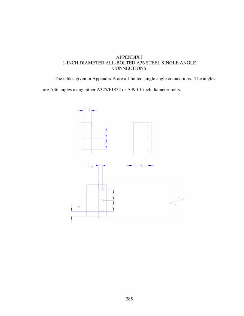
285
APPENDIX I 1-INCH DIAMETER ALL-BOLTED A36 STEEL SINGLE ANGLE
CONNECTIONS
The tables given in Appendix A are all-bolted single angle connections. The angles
are A36 angles using either A325/F1852 or A490 1-inch diameter bolts.

286
Notes: Angles are assumed to be A36 Steel Supporting and supported members are assumed to be A992 Steel Leh is assumed to be 1.25 in. Represents a bolt bearing limit state Represents a bolt shear limit state Represents a slip-critical limit state All-Bolted Extended Single-Angle Connections
N (# of Bolts)
Bolt Diameter
Angle Outstanding
Leg
ASTM Desig.
Thread Cond.
Hole Type
Angle Thickness
3/8 1/2 5/8 N 7.6 10.2 12.7 X 7.6 10.2 12.7 STD 7.6 10.2 10.3 OVS 6.6 8.8 8.8
SC Class A
SSLT 7.6 8.8 8.8 STD 7.6 10.2 12.7 OVS 6.6 8.8 11.1
A325/ F1852
SC Class B
SSLT 7.6 10.2 12.7 N 7.6 10.2 12.7 X 7.6 10.2 12.7 STD 7.6 10.2 12.7 OVS 6.6 8.8 11.0
SC Class A
SSLT 7.6 10.2 11.0 STD 7.6 10.2 12.7 OVS 6.6 8.8 11.1
2 1 6
A490
SC Class B
SSLT 7.6 10.2 12.7 All-Bolted Extended Single-Angle Connections
N (# of Bolts)
Bolt Diameter
Angle Outstanding
Leg
ASTM Desig.
Thread Cond.
Hole Type
Angle Thickness
3/8 1/2 5/8 N 17.1 22.7 28.4 X 17.1 22.7 28.4 STD 17.1 22.7 23.0 OVS 14.8 19.6 19.6
SC Class A
SSLT 17.1 19.6 19.6 STD 17.1 22.7 28.4 OVS 14.8 19.8 24.7
A325/ F1852
SC Class B
SSLT 17.1 22.7 28.4 N 17.1 22.7 28.4 X 17.1 22.7 28.4 STD 17.1 22.7 28.4 OVS 14.8 19.8 24.6
SC Class A
SSLT 17.1 22.7 24.6 STD 17.1 22.7 28.4 OVS 14.8 19.8 24.7
3 1 6
A490
SC Class B
SSLT 17.1 22.7 28.4

287
Notes: Angles are assumed to be A36 Steel Supporting and supported members are assumed to be A992 Steel Leh is assumed to be 1.25 in. Represents a bolt bearing limit state Represents a bolt shear limit state Represents a slip-critical limit state All-Bolted Extended Single-Angle Connections
N (# of Bolts)
Bolt Diameter
Angle Outstanding
Leg
ASTM Desig.
Thread Cond.
Hole Type
Angle Thickness
3/8 1/2 5/8 N 29.5 39.3 49.2 X 29.5 39.3 49.2 STD 29.5 39.3 39.9 OVS 25.6 34.0 34.0
SC Class A
SSLT 29.5 34.0 34.0 STD 29.5 39.3 49.2 OVS 25.6 34.2 42.7
A325/ F1852
SC Class B
SSLT 29.5 39.3 49.2 N 29.5 39.3 49.2 X 29.5 39.3 49.2 STD 29.5 39.3 49.2 OVS 25.6 34.2 42.6
SC Class A
SSLT 29.5 39.3 42.6 STD 29.5 39.3 49.2 OVS 25.6 34.2 42.7
4 1 6
A490
SC Class B
SSLT 29.5 39.3 49.2 All-Bolted Extended Single-Angle Connections
N (# of Bolts)
Bolt Diameter
Angle Outstanding
Leg
ASTM Desig.
Thread Cond.
Hole Type
Angle Thickness
3/8 1/2 5/8 N 43.2 57.6 72.0 X 43.2 57.6 72.0 STD 43.2 57.6 58.3 OVS 37.5 49.7 49.7
SC Class A
SSLT 43.2 49.7 49.7 STD 43.2 57.6 72.0 OVS 37.5 50.0 62.6
A325/ F1852
SC Class B
SSLT 43.2 57.6 72.0 N 43.2 57.6 72.0 X 43.2 57.6 72.0 STD 43.2 57.6 72.0 OVS 37.5 50.0 62.3
SC Class A
SSLT 43.2 57.6 62.3 STD 43.2 57.6 72.0 OVS 37.5 50.0 62.6
5 1 6
A490
SC Class B
SSLT 43.2 57.6 72.0

288
Notes: Angles are assumed to be A36 Steel Supporting and supported members are assumed to be A992 Steel Leh is assumed to be 1.25 in. Represents a bolt bearing limit state Represents a bolt shear limit state Represents a slip-critical limit state All-Bolted Extended Single-Angle Connections
N (# of Bolts)
Bolt Diameter
Angle Outstanding
Leg
ASTM Desig.
Thread Cond.
Hole Type
Angle Thickness
3/8 1/2 5/8 N 57.7 76.9 96.2 X 57.7 76.9 96.2 STD 57.7 76.9 77.9 OVS 50.2 66.5 66.5
SC Class A
SSLT 57.7 66.5 66.5 STD 57.7 76.9 96.2 OVS 50.2 66.9 83.6
A325/ F1852
SC Class B
SSLT 57.7 76.9 96.2 N 57.7 76.9 96.2 X 57.7 76.9 96.2 STD 57.7 76.9 96.2 OVS 50.2 66.9 83.3
SC Class A
SSLT 57.7 76.9 83.3 STD 57.7 76.9 96.2 OVS 50.2 66.9 83.6
6 1 6
A490
SC Class B
SSLT 57.7 76.9 96.2 All-Bolted Extended Single-Angle Connections
N (# of Bolts)
Bolt Diameter
Angle Outstanding
Leg
ASTM Desig.
Thread Cond.
Hole Type
Angle Thickness
3/8 1/2 5/8 N 72.9 97.2 121.5 X 72.9 97.2 121.5 STD 72.9 97.2 98.5 OVS 63.4 84.0 84.0
SC Class A
SSLT 72.9 84.0 84.0 STD 72.9 97.2 121.5 OVS 63.4 84.5 105.6
A325/ F1852
SC Class B
SSLT 72.9 97.2 121.5 N 72.9 97.2 121.5 X 72.9 97.2 121.5 STD 72.9 97.2 121.5 OVS 63.4 84.5 105.3
SC Class A
SSLT 72.9 97.2 105.3 STD 72.9 97.2 121.5 OVS 63.4 84.5 105.6
7 1 6
A490
SC Class B
SSLT 72.9 97.2 121.5

289
Notes: Angles are assumed to be A36 Steel Supporting and supported members are assumed to be A992 Steel Leh is assumed to be 1.25 in. Represents a bolt bearing limit state Represents a bolt shear limit state Represents a slip-critical limit state All-Bolted Extended Single-Angle Connections
N (# of Bolts)
Bolt Diameter
Angle Outstanding
Leg
ASTM Desig.
Thread Cond.
Hole Type
Angle Thickness
3/8 1/2 5/8 N 88.0 117.3 146.7 X 88.0 117.3 146.7 STD 88.0 117.3 118.9 OVS 76.5 101.4 101.4
SC Class A
SSLT 88.0 101.4 101.4 STD 88.0 117.3 146.7 OVS 76.5 102.0 127.5
A325/ F1852
SC Class B
SSLT 88.0 117.3 146.7 N 88.0 117.3 146.7 X 88.0 117.3 146.7 STD 88.0 117.3 146.7 OVS 76.5 102.0 127.0
SC Class A
SSLT 88.0 117.3 127.0 STD 88.0 117.3 146.7 OVS 76.5 102.0 127.5
8 1 6
A490
SC Class B
SSLT 88.0 117.3 146.7 All-Bolted Extended Single-Angle Connections
N (# of Bolts)
Bolt Diameter
Angle Outstanding
Leg
ASTM Desig.
Thread Cond.
Hole Type
Angle Thickness
3/8 1/2 5/8 N 103.3 137.7 172.1 X 103.3 137.7 172.1 STD 103.3 137.7 139.6 OVS 89.8 119.0 119.0
SC Class A
SSLT 103.3 119.0 119.0 STD 103.3 137.7 172.1 OVS 89.8 119.7 149.7
A325/ F1852
SC Class B
SSLT 103.3 137.7 172.1 N 103.3 137.7 172.1 X 103.3 137.7 172.1 STD 103.3 137.7 172.1 OVS 89.8 119.7 149.1
SC Class A
SSLT 103.3 137.7 149.1 STD 103.3 137.7 172.1 OVS 89.8 119.7 149.7
9 1 6
A490
SC Class B
SSLT 103.3 137.7 172.1

290
Notes: Angles are assumed to be A36 Steel Supporting and supported members are assumed to be A992 Steel Leh is assumed to be 1.25 in. Represents a bolt bearing limit state Represents a bolt shear limit state Represents a slip-critical limit state All-Bolted Extended Single-Angle Connections
N (# of Bolts)
Bolt Diameter
Angle Outstanding
Leg
ASTM Desig.
Thread Cond.
Hole Type
Angle Thickness
3/8 1/2 5/8 N 118.4 157.9 197.3 X 118.4 157.9 197.3 STD 118.4 157.9 160.0 OVS 102.9 136.4 136.4
SC Class A
SSLT 118.4 136.4 136.4 STD 118.4 157.9 197.3 OVS 102.9 137.2 171.6
A325/ F1852
SC Class B
SSLT 118.4 157.9 197.3 N 118.4 157.9 197.3 X 118.4 157.9 197.3 STD 118.4 157.9 197.3 OVS 102.9 137.2 170.9
SC Class A
SSLT 118.4 157.9 170.9 STD 118.4 157.9 197.3 OVS 102.9 137.2 171.6
10 1 6
A490
SC Class B
SSLT 118.4 157.9 197.3 All-Bolted Extended Single-Angle Connections
N (# of Bolts)
Bolt Diameter
Angle Outstanding
Leg
ASTM Desig.
Thread Cond.
Hole Type
Angle Thickness
3/8 1/2 5/8 N 133.5 178.0 222.5 X 133.5 178.0 222.5 STD 133.5 178.0 180.4 OVS 116.1 153.8 153.8
SC Class A
SSLT 133.5 153.8 153.8 STD 133.5 178.0 222.5 OVS 116.1 154.8 193.5
A325/ F1852
SC Class B
SSLT 133.5 178.0 222.5 N 133.5 178.0 222.5 X 133.5 178.0 222.5 STD 133.5 178.0 222.5 OVS 116.1 154.8 192.7
SC Class A
SSLT 133.5 178.0 192.7 STD 133.5 178.0 222.5 OVS 116.1 154.8 193.5
11 1 6
A490
SC Class B
SSLT 133.5 178.0 222.5

291
Notes: Angles are assumed to be A36 Steel Supporting and supported members are assumed to be A992 Steel Leh is assumed to be 1.25 in. Represents a bolt bearing limit state Represents a bolt shear limit state Represents a slip-critical limit state All-Bolted Extended Single-Angle Connections
N (# of Bolts)
Bolt Diameter
Angle Outstanding
Leg
ASTM Desig.
Thread Cond.
Hole Type
Angle Thickness
3/8 1/2 5/8 N 148.0 197.3 246.7 X 148.0 197.3 246.7 STD 148.0 197.3 200.0 OVS 128.7 170.5 170.5
SC Class A
SSLT 148.0 170.5 170.5 STD 148.0 197.3 246.7 OVS 128.7 171.6 214.4
A325/ F1852
SC Class B
SSLT 148.0 197.3 246.7 N 148.0 197.3 246.7 X 148.0 197.3 246.7 STD 148.0 197.3 246.7 OVS 128.7 171.6 213.7
SC Class A
SSLT 148.0 197.3 213.7 STD 148.0 197.3 246.7 OVS 128.7 171.6 214.4
12 1 6
A490
SC Class B
SSLT 148.0 197.3 246.7

292
Notes: Angles are assumed to be A36 Steel Supporting and supported members are assumed to be A992 Steel Leh is assumed to be 1.25 in. Represents a bolt bearing limit state Represents a bolt shear limit state Represents a slip-critical limit state All-Bolted Extended Single-Angle Connections
N (# of Bolts)
Bolt Diameter
Angle Outstanding
Leg
ASTM Desig.
Thread Cond.
Hole Type
Angle Thickness
3/8 1/2 5/8 N 7.0 9.4 11.7 X 7.0 9.4 11.7 STD 7.0 9.4 9.5 OVS 6.1 8.1 8.1
SC Class A
SSLT 7.0 8.1 8.1 STD 7.0 9.4 11.7 OVS 6.1 8.2 10.2
A325/ F1852
SC Class B
SSLT 7.0 9.4 11.7 N 7.0 9.4 11.7 X 7.0 9.4 11.7 STD 7.0 9.4 11.7 OVS 6.1 8.2 10.2
SC Class A
SSLT 7.0 9.4 10.2 STD 7.0 9.4 11.7 OVS 6.1 8.2 10.2
2 1 7
A490
SC Class B
SSLT 7.0 9.4 11.7 All-Bolted Extended Single-Angle Connections
N (# of Bolts)
Bolt Diameter
Angle Outstanding
Leg
ASTM Desig.
Thread Cond.
Hole Type
Angle Thickness
3/8 1/2 5/8 N 14.3 19.0 23.8 X 14.3 19.0 23.8 STD 14.3 19.0 19.3 OVS 12.4 16.4 16.4
SC Class A
SSLT 14.3 16.4 16.4 STD 14.3 19.0 23.8 OVS 12.4 16.5 20.7
A325/ F1852
SC Class B
SSLT 14.3 19.0 23.8 N 14.3 19.0 23.8 X 14.3 19.0 23.8 STD 14.3 19.0 23.8 OVS 12.4 16.5 20.6
SC Class A
SSLT 14.3 19.0 20.6 STD 14.3 19.0 23.8 OVS 12.4 16.5 20.7
3 1 7
A490
SC Class B
SSLT 14.3 19.0 23.8

293
Notes: Angles are assumed to be A36 Steel Supporting and supported members are assumed to be A992 Steel Leh is assumed to be 1.25 in. Represents a bolt bearing limit state Represents a bolt shear limit state Represents a slip-critical limit state All-Bolted Extended Single-Angle Connections
N (# of Bolts)
Bolt Diameter
Angle Outstanding
Leg
ASTM Desig.
Thread Cond.
Hole Type
Angle Thickness
3/8 1/2 5/8 N 25.6 34.2 42.7 X 25.6 34.2 42.7 STD 25.6 34.2 34.6 OVS 22.3 29.5 29.5
SC Class A
SSLT 25.6 29.5 29.5 STD 25.6 34.2 42.7 OVS 22.3 29.7 37.1
A325/ F1852
SC Class B
SSLT 25.6 34.2 42.7 N 25.6 34.2 42.7 X 25.6 34.2 42.7 STD 25.6 34.2 42.7 OVS 22.3 29.7 37.0
SC Class A
SSLT 25.6 34.2 37.0 STD 25.6 34.2 42.7 OVS 22.3 29.7 37.1
4 1 7
A490
SC Class B
SSLT 25.6 34.2 42.7 All-Bolted Extended Single-Angle Connections
N (# of Bolts)
Bolt Diameter
Angle Outstanding
Leg
ASTM Desig.
Thread Cond.
Hole Type
Angle Thickness
3/8 1/2 5/8 N 37.7 50.3 62.9 X 37.7 50.3 62.9 STD 37.7 50.3 51.0 OVS 32.8 43.5 43.5
SC Class A
SSLT 37.7 43.5 43.5 STD 37.7 50.3 62.9 OVS 32.8 43.7 54.7
A325/ F1852
SC Class B
SSLT 37.7 50.3 62.9 N 37.7 50.3 62.9 X 37.7 50.3 62.9 STD 37.7 50.3 62.9 OVS 32.8 43.7 54.5
SC Class A
SSLT 37.7 50.3 54.5 STD 37.7 50.3 62.9 OVS 32.8 43.7 54.7
5 1 7
A490
SC Class B
SSLT 37.7 50.3 62.9

294
Notes: Angles are assumed to be A36 Steel Supporting and supported members are assumed to be A992 Steel Leh is assumed to be 1.25 in. Represents a bolt bearing limit state Represents a bolt shear limit state Represents a slip-critical limit state All-Bolted Extended Single-Angle Connections
N (# of Bolts)
Bolt Diameter
Angle Outstanding
Leg
ASTM Desig.
Thread Cond.
Hole Type
Angle Thickness
3/8 1/2 5/8 N 51.4 68.6 85.7 X 51.4 68.6 85.7 STD 51.4 68.6 69.5 OVS 44.7 59.3 59.3
SC Class A
SSLT 51.4 59.3 59.3 STD 51.4 68.6 85.7 OVS 44.7 59.6 74.5
A325/ F1852
SC Class B
SSLT 51.4 68.6 85.7 N 51.4 68.6 85.7 X 51.4 68.6 85.7 STD 51.4 68.6 85.7 OVS 44.7 59.6 74.2
SC Class A
SSLT 51.4 68.6 74.2 STD 51.4 68.6 85.7 OVS 44.7 59.6 74.5
6 1 7
A490
SC Class B
SSLT 51.4 68.6 85.7 All-Bolted Extended Single-Angle Connections
N (# of Bolts)
Bolt Diameter
Angle Outstanding
Leg
ASTM Desig.
Thread Cond.
Hole Type
Angle Thickness
3/8 1/2 5/8 N 66.0 87.9 109.9 X 66.0 87.9 109.9 STD 66.0 87.9 89.1 OVS 57.3 76.0 76.0
SC Class A
SSLT 66.0 76.0 76.0 STD 66.0 87.9 109.9 OVS 57.3 76.4 95.6
A325/ F1852
SC Class B
SSLT 66.0 87.9 109.9 N 66.0 87.9 109.9 X 66.0 87.9 109.9 STD 66.0 87.9 109.9 OVS 57.3 76.4 95.2
SC Class A
SSLT 66.0 87.9 95.2 STD 66.0 87.9 109.9 OVS 57.3 76.4 95.6
7 1 7
A490
SC Class B
SSLT 66.0 87.9 109.9

295
Notes: Angles are assumed to be A36 Steel Supporting and supported members are assumed to be A992 Steel Leh is assumed to be 1.25 in. Represents a bolt bearing limit state Represents a bolt shear limit state Represents a slip-critical limit state All-Bolted Extended Single-Angle Connections
N (# of Bolts)
Bolt Diameter
Angle Outstanding
Leg
ASTM Desig.
Thread Cond.
Hole Type
Angle Thickness
3/8 1/2 5/8 N 80.9 107.9 134.9 X 80.9 107.9 134.9 STD 80.9 107.9 109.3 OVS 70.4 93.2 93.2
SC Class A
SSLT 80.9 93.2 93.2 STD 80.9 107.9 134.9 OVS 70.4 93.8 117.3
A325/ F1852
SC Class B
SSLT 80.9 107.9 134.9 N 80.9 107.9 134.9 X 80.9 107.9 134.9 STD 80.9 107.9 134.9 OVS 70.4 93.8 116.8
SC Class A
SSLT 80.9 107.9 116.8 STD 80.9 107.9 134.9 OVS 70.4 93.8 117.3
8 1 7
A490
SC Class B
SSLT 80.9 107.9 134.9 All-Bolted Extended Single-Angle Connections
N (# of Bolts)
Bolt Diameter
Angle Outstanding
Leg
ASTM Desig.
Thread Cond.
Hole Type
Angle Thickness
3/8 1/2 5/8 N 96.0 128.1 160.1 X 96.0 128.1 160.1 STD 96.0 128.1 129.8 OVS 83.5 110.6 110.6
SC Class A
SSLT 96.0 110.6 110.6 STD 96.0 128.1 160.1 OVS 83.5 111.3 139.2
A325/ F1852
SC Class B
SSLT 96.0 128.1 160.1 N 96.0 128.1 160.1 X 96.0 128.1 160.1 STD 96.0 128.1 160.1 OVS 83.5 111.3 138.6
SC Class A
SSLT 96.0 128.1 138.6 STD 96.0 128.1 160.1 OVS 83.5 111.3 139.2
9 1 7
A490
SC Class B
SSLT 96.0 128.1 160.1

296
Notes: Angles are assumed to be A36 Steel Supporting and supported members are assumed to be A992 Steel Leh is assumed to be 1.25 in. Represents a bolt bearing limit state Represents a bolt shear limit state Represents a slip-critical limit state All-Bolted Extended Single-Angle Connections
N (# of Bolts)
Bolt Diameter
Angle Outstanding
Leg
ASTM Desig.
Thread Cond.
Hole Type
Angle Thickness
3/8 1/2 5/8 N 111.3 148.5 185.6 X 111.3 148.5 185.6 STD 111.3 148.5 150.4 OVS 96.8 128.3 128.3
SC Class A
SSLT 111.3 128.3 128.3 STD 111.3 148.5 185.6 OVS 96.8 129.1 161.3
A325/ F1852
SC Class B
SSLT 111.3 148.5 185.6 N 111.3 148.5 185.6 X 111.3 148.5 185.6 STD 111.3 148.5 185.6 OVS 96.8 129.1 160.7
SC Class A
SSLT 111.3 148.5 160.7 STD 111.3 148.5 185.6 OVS 96.8 129.1 161.3
10 1 7
A490
SC Class B
SSLT 111.3 148.5 185.6 All-Bolted Extended Single-Angle Connections
N (# of Bolts)
Bolt Diameter
Angle Outstanding
Leg
ASTM Desig.
Thread Cond.
Hole Type
Angle Thickness
3/8 1/2 5/8 N 127.6 170.1 212.6 X 127.6 170.1 212.6 STD 127.6 170.1 172.4 OVS 110.9 147.0 147.0
SC Class A
SSLT 127.6 147.0 147.0 STD 127.6 170.1 212.6 OVS 110.9 147.9 184.9
A325/ F1852
SC Class B
SSLT 127.6 170.1 212.6 N 127.6 170.1 212.6 X 127.6 170.1 212.6 STD 127.6 170.1 212.6 OVS 110.9 147.9 184.2
SC Class A
SSLT 127.6 170.1 184.2 STD 127.6 170.1 212.6 OVS 110.9 147.9 184.9
11 1 7
A490
SC Class B
SSLT 127.6 170.1 212.6

297
Notes: Angles are assumed to be A36 Steel Supporting and supported members are assumed to be A992 Steel Leh is assumed to be 1.25 in. Represents a bolt bearing limit state Represents a bolt shear limit state Represents a slip-critical limit state All-Bolted Extended Single-Angle Connections
N (# of Bolts)
Bolt Diameter
Angle Outstanding
Leg
ASTM Desig.
Thread Cond.
Hole Type
Angle Thickness
3/8 1/2 5/8 N 141.6 188.8 236.0 X 141.6 188.8 236.0 STD 141.6 188.8 191.3 OVS 123.1 163.1 163.1
SC Class A
SSLT 141.6 163.1 163.1 STD 141.6 188.8 236.0 OVS 123.1 164.1 205.2
A325/ F1852
SC Class B
SSLT 141.6 188.8 236.0 N 141.6 188.8 236.0 X 141.6 188.8 236.0 STD 141.6 188.8 236.0 OVS 123.1 164.1 204.4
SC Class A
SSLT 141.6 188.8 204.4 STD 141.6 188.8 236.0 OVS 123.1 164.1 205.2
12 1 7
A490
SC Class B
SSLT 141.6 188.8 236.0

298
Notes: Angles are assumed to be A36 Steel Supporting and supported members are assumed to be A992 Steel Leh is assumed to be 1.25 in. Represents a bolt bearing limit state Represents a bolt shear limit state Represents a slip-critical limit state All-Bolted Extended Single-Angle Connections
N (# of Bolts)
Bolt Diameter
Angle Outstanding
Leg
ASTM Desig.
Thread Cond.
Hole Type
Angle Thickness
3/8 1/2 5/8 N 6.1 8.1 10.2 X 6.1 8.1 10.2 STD 6.1 8.1 8.2 OVS 5.3 7.0 7.0
SC Class A
SSLT 6.1 7.0 7.0 STD 6.1 8.1 10.2 OVS 5.3 7.1 8.8
A325/ F1852
SC Class B
SSLT 6.1 8.1 10.2 N 6.1 8.1 10.2 X 6.1 8.1 10.2 STD 6.1 8.1 10.2 OVS 5.3 7.1 8.8
SC Class A
SSLT 6.1 8.1 8.8 STD 6.1 8.1 10.2 OVS 5.3 7.1 8.8
2 1 8
A490
SC Class B
SSLT 6.1 8.1 10.2 All-Bolted Extended Single-Angle Connections
N (# of Bolts)
Bolt Diameter
Angle Outstanding
Leg
ASTM Desig.
Thread Cond.
Hole Type
Angle Thickness
3/8 1/2 5/8 N 12.3 16.4 20.5 X 12.3 16.4 20.5 STD 12.3 16.4 16.6 OVS 10.7 14.2 14.2
SC Class A
SSLT 12.3 14.2 14.2 STD 12.3 16.4 20.5 OVS 10.7 14.3 17.9
A325/ F1852
SC Class B
SSLT 12.3 16.4 20.5 N 12.3 16.4 20.5 X 12.3 16.4 20.5 STD 12.3 16.4 20.5 OVS 10.7 14.3 17.8
SC Class A
SSLT 12.3 16.4 17.8 STD 12.3 16.4 20.5 OVS 10.7 14.3 17.9
3 1 8
A490
SC Class B
SSLT 12.3 16.4 20.5

299
Notes: Angles are assumed to be A36 Steel Supporting and supported members are assumed to be A992 Steel Leh is assumed to be 1.25 in. Represents a bolt bearing limit state Represents a bolt shear limit state Represents a slip-critical limit state All-Bolted Extended Single-Angle Connections
N (# of Bolts)
Bolt Diameter
Angle Outstanding
Leg
ASTM Desig.
Thread Cond.
Hole Type
Angle Thickness
3/8 1/2 5/8 N 22.3 29.7 37.1 X 22.3 29.7 37.1 STD 22.3 29.7 30.1 OVS 19.3 25.6 25.6
SC Class A
SSLT 22.3 25.6 25.6 STD 22.3 29.7 37.1 OVS 19.3 25.8 32.2
A325/ F1852
SC Class B
SSLT 22.3 29.7 37.1 N 22.3 29.7 37.1 X 22.3 29.7 37.1 STD 22.3 29.7 37.1 OVS 19.3 25.8 32.1
SC Class A
SSLT 22.3 29.7 32.1 STD 22.3 29.7 37.1 OVS 19.3 25.8 32.2
4 1 8
A490
SC Class B
SSLT 22.3 29.7 37.1 All-Bolted Extended Single-Angle Connections
N (# of Bolts)
Bolt Diameter
Angle Outstanding
Leg
ASTM Desig.
Thread Cond.
Hole Type
Angle Thickness
3/8 1/2 5/8 N 33.5 44.7 55.8 X 33.5 44.7 55.8 STD 33.5 44.7 45.3 OVS 29.1 38.6 38.6
SC Class A
SSLT 33.5 38.6 38.6 STD 33.5 44.7 55.8 OVS 29.1 38.8 48.5
A325/ F1852
SC Class B
SSLT 33.5 44.7 55.8 N 33.5 44.7 55.8 X 33.5 44.7 55.8 STD 33.5 44.7 55.8 OVS 29.1 38.8 48.4
SC Class A
SSLT 33.5 44.7 48.4 STD 33.5 44.7 55.8 OVS 29.1 38.8 48.5
5 1 8
A490
SC Class B
SSLT 33.5 44.7 55.8

300
Notes: Angles are assumed to be A36 Steel Supporting and supported members are assumed to be A992 Steel Leh is assumed to be 1.25 in. Represents a bolt bearing limit state Represents a bolt shear limit state Represents a slip-critical limit state All-Bolted Extended Single-Angle Connections
N (# of Bolts)
Bolt Diameter
Angle Outstanding
Leg
ASTM Desig.
Thread Cond.
Hole Type
Angle Thickness
3/8 1/2 5/8 N 46.3 61.8 77.2 X 46.3 61.8 77.2 STD 46.3 61.8 62.6 OVS 40.3 53.4 53.4
SC Class A
SSLT 46.3 53.4 53.4 STD 46.3 61.8 77.2 OVS 40.3 53.7 67.1
A325/ F1852
SC Class B
SSLT 46.3 61.8 77.2 N 46.3 61.8 77.2 X 46.3 61.8 77.2 STD 46.3 61.8 77.2 OVS 40.3 53.7 66.9
SC Class A
SSLT 46.3 61.8 66.9 STD 46.3 61.8 77.2 OVS 40.3 53.7 67.1
6 1 8
A490
SC Class B
SSLT 46.3 61.8 77.2 All-Bolted Extended Single-Angle Connections
N (# of Bolts)
Bolt Diameter
Angle Outstanding
Leg
ASTM Desig.
Thread Cond.
Hole Type
Angle Thickness
3/8 1/2 5/8 N 60.1 80.2 100.2 X 60.1 80.2 100.2 STD 60.1 80.2 81.2 OVS 52.3 69.3 69.3
SC Class A
SSLT 60.1 69.3 69.3 STD 60.1 80.2 100.2 OVS 52.3 69.7 87.1
A325/ F1852
SC Class B
SSLT 60.1 80.2 100.2 N 60.1 80.2 100.2 X 60.1 80.2 100.2 STD 60.1 80.2 100.2 OVS 52.3 69.7 86.8
SC Class A
SSLT 60.1 80.2 86.8 STD 60.1 80.2 100.2 OVS 52.3 69.7 87.1
7 1 8
A490
SC Class B
SSLT 60.1 80.2 100.2

301
Notes: Angles are assumed to be A36 Steel Supporting and supported members are assumed to be A992 Steel Leh is assumed to be 1.25 in. Represents a bolt bearing limit state Represents a bolt shear limit state Represents a slip-critical limit state All-Bolted Extended Single-Angle Connections
N (# of Bolts)
Bolt Diameter
Angle Outstanding
Leg
ASTM Desig.
Thread Cond.
Hole Type
Angle Thickness
3/8 1/2 5/8 N 74.6 99.5 124.4 X 74.6 99.5 124.4 STD 74.6 99.5 100.9 OVS 64.9 86.0 86.0
SC Class A
SSLT 74.6 86.0 86.0 STD 74.6 99.5 124.4 OVS 64.9 86.5 108.2
A325/ F1852
SC Class B
SSLT 74.6 99.5 124.4 N 74.6 99.5 124.4 X 74.6 99.5 124.4 STD 74.6 99.5 124.4 OVS 64.9 86.5 107.8
SC Class A
SSLT 74.6 99.5 107.8 STD 74.6 99.5 124.4 OVS 64.9 86.5 108.2
8 1 8
A490
SC Class B
SSLT 74.6 99.5 124.4 All-Bolted Extended Single-Angle Connections
N (# of Bolts)
Bolt Diameter
Angle Outstanding
Leg
ASTM Desig.
Thread Cond.
Hole Type
Angle Thickness
3/8 1/2 5/8 N 89.5 119.3 149.2 X 89.5 119.3 149.2 STD 89.5 119.3 120.9 OVS 77.8 103.1 103.1
SC Class A
SSLT 89.5 103.1 103.1 STD 89.5 119.3 149.2 OVS 77.8 103.7 129.7
A325/ F1852
SC Class B
SSLT 89.5 119.3 149.2 N 89.5 119.3 149.2 X 89.5 119.3 149.2 STD 89.5 119.3 149.2 OVS 77.8 103.7 129.2
SC Class A
SSLT 89.5 119.3 129.2 STD 89.5 119.3 149.2 OVS 77.8 103.7 129.7
9 1 8
A490
SC Class B
SSLT 89.5 119.3 149.2

302
Notes: Angles are assumed to be A36 Steel Supporting and supported members are assumed to be A992 Steel Leh is assumed to be 1.25 in. Represents a bolt bearing limit state Represents a bolt shear limit state Represents a slip-critical limit state All-Bolted Extended Single-Angle Connections
N (# of Bolts)
Bolt Diameter
Angle Outstanding
Leg
ASTM Desig.
Thread Cond.
Hole Type
Angle Thickness
3/8 1/2 5/8 N 104.7 139.7 174.6 X 104.7 139.7 174.6 STD 104.7 139.7 141.5 OVS 91.1 120.7 120.7
SC Class A
SSLT 104.7 120.7 120.7 STD 104.7 139.7 174.6 OVS 91.1 121.4 151.8
A325/ F1852
SC Class B
SSLT 104.7 139.7 174.6 N 104.7 139.7 174.6 X 104.7 139.7 174.6 STD 104.7 139.7 174.6 OVS 91.1 121.4 151.2
SC Class A
SSLT 104.7 139.7 151.2 STD 104.7 139.7 174.6 OVS 91.1 121.4 151.8
10 1 8
A490
SC Class B
SSLT 104.7 139.7 174.6 All-Bolted Extended Single-Angle Connections
N (# of Bolts)
Bolt Diameter
Angle Outstanding
Leg
ASTM Desig.
Thread Cond.
Hole Type
Angle Thickness
3/8 1/2 5/8 N 119.9 159.9 199.9 X 119.9 159.9 199.9 STD 119.9 159.9 162.0 OVS 104.3 138.2 138.2
SC Class A
SSLT 119.9 138.2 138.2 STD 119.9 159.9 199.9 OVS 104.3 139.0 173.8
A325/ F1852
SC Class B
SSLT 119.9 159.9 199.9 N 119.9 159.9 199.9 X 119.9 159.9 199.9 STD 119.9 159.9 199.9 OVS 104.3 139.0 173.1
SC Class A
SSLT 119.9 159.9 173.1 STD 119.9 159.9 199.9 OVS 104.3 139.0 173.8
11 1 8
A490
SC Class B
SSLT 119.9 159.9 199.9

303
Notes: Angles are assumed to be A36 Steel Supporting and supported members are assumed to be A992 Steel Leh is assumed to be 1.25 in. Represents a bolt bearing limit state Represents a bolt shear limit state Represents a slip-critical limit state All-Bolted Extended Single-Angle Connections
N (# of Bolts)
Bolt Diameter
Angle Outstanding
Leg
ASTM Desig.
Thread Cond.
Hole Type
Angle Thickness
3/8 1/2 5/8 N 135.2 180.2 225.3 X 135.2 180.2 225.3 STD 135.2 180.2 182.6 OVS 117.5 155.7 155.7
SC Class A
SSLT 135.2 155.7 155.7 STD 135.2 180.2 225.3 OVS 117.5 156.7 195.8
A325/ F1852
SC Class B
SSLT 135.2 180.2 225.3 N 135.2 180.2 225.3 X 135.2 180.2 225.3 STD 135.2 180.2 225.3 OVS 117.5 156.7 195.1
SC Class A
SSLT 135.2 180.2 195.1 STD 135.2 180.2 225.3 OVS 117.5 156.7 195.8
12 1 8
A490
SC Class B
SSLT 135.2 180.2 225.3

304
Notes: Angles are assumed to be A36 Steel Supporting and supported members are assumed to be A992 Steel Leh is assumed to be 1.25 in. Represents a bolt bearing limit state Represents a bolt shear limit state Represents a slip-critical limit state All-Bolted Extended Single-Angle Connections
N (# of Bolts)
Bolt Diameter
Angle Outstanding
Leg
ASTM Desig.
Thread Cond.
Hole Type
Angle Thickness
3/8 1/2 5/8 N 4.6 6.1 7.6 X 4.6 6.1 7.6 STD 4.6 6.1 6.2 OVS 4.0 5.3 5.3
SC Class A
SSLT 4.6 5.3 5.3 STD 4.6 6.1 7.6 OVS 4.0 5.3 6.6
A325/ F1852
SC Class B
SSLT 4.6 6.1 7.6 N 4.6 6.1 7.6 X 4.6 6.1 7.6 STD 4.6 6.1 7.6 OVS 4.0 5.3 6.6
SC Class A
SSLT 4.6 6.1 6.6 STD 4.6 6.1 7.6 OVS 4.0 5.3 6.6
2 1 9
A490
SC Class B
SSLT 4.6 6.1 7.6 All-Bolted Extended Single-Angle Connections
N (# of Bolts)
Bolt Diameter
Angle Outstanding
Leg
ASTM Desig.
Thread Cond.
Hole Type
Angle Thickness
3/8 1/2 5/8 N 10.6 14.2 17.7 X 10.6 14.2 17.7 STD 10.6 14.2 14.3 OVS 9.2 12.2 12.2
SC Class A
SSLT 10.6 12.2 12.2 STD 10.6 14.2 17.7 OVS 9.2 12.3 15.4
A325/ F1852
SC Class B
SSLT 10.6 14.2 17.7 N 10.6 14.2 17.7 X 10.6 14.2 17.7 STD 10.6 14.2 17.7 OVS 9.2 12.3 15.3
SC Class A
SSLT 10.6 14.2 15.3 STD 10.6 14.2 17.7 OVS 9.2 12.3 15.4
3 1 9
A490
SC Class B
SSLT 10.6 14.2 17.7
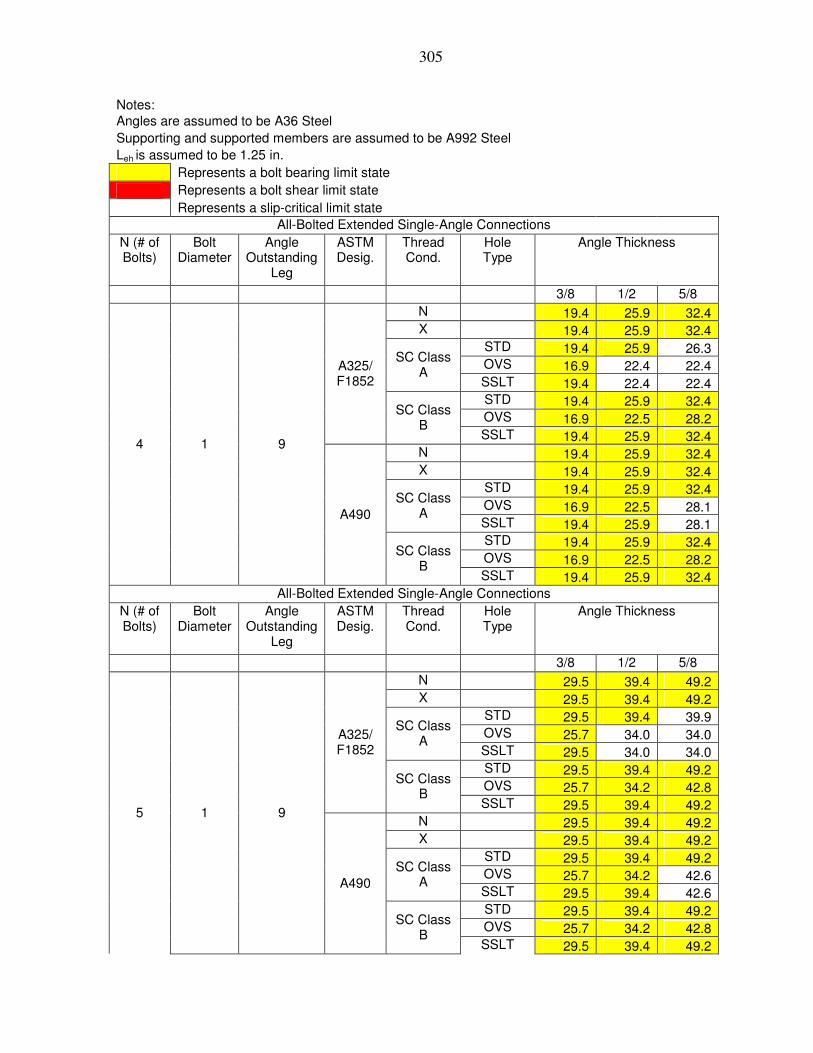
305
Notes: Angles are assumed to be A36 Steel Supporting and supported members are assumed to be A992 Steel Leh is assumed to be 1.25 in. Represents a bolt bearing limit state Represents a bolt shear limit state Represents a slip-critical limit state All-Bolted Extended Single-Angle Connections
N (# of Bolts)
Bolt Diameter
Angle Outstanding
Leg
ASTM Desig.
Thread Cond.
Hole Type
Angle Thickness
3/8 1/2 5/8 N 19.4 25.9 32.4 X 19.4 25.9 32.4 STD 19.4 25.9 26.3 OVS 16.9 22.4 22.4
SC Class A
SSLT 19.4 22.4 22.4 STD 19.4 25.9 32.4 OVS 16.9 22.5 28.2
A325/ F1852
SC Class B
SSLT 19.4 25.9 32.4 N 19.4 25.9 32.4 X 19.4 25.9 32.4 STD 19.4 25.9 32.4 OVS 16.9 22.5 28.1
SC Class A
SSLT 19.4 25.9 28.1 STD 19.4 25.9 32.4 OVS 16.9 22.5 28.2
4 1 9
A490
SC Class B
SSLT 19.4 25.9 32.4 All-Bolted Extended Single-Angle Connections
N (# of Bolts)
Bolt Diameter
Angle Outstanding
Leg
ASTM Desig.
Thread Cond.
Hole Type
Angle Thickness
3/8 1/2 5/8 N 29.5 39.4 49.2 X 29.5 39.4 49.2 STD 29.5 39.4 39.9 OVS 25.7 34.0 34.0
SC Class A
SSLT 29.5 34.0 34.0 STD 29.5 39.4 49.2 OVS 25.7 34.2 42.8
A325/ F1852
SC Class B
SSLT 29.5 39.4 49.2 N 29.5 39.4 49.2 X 29.5 39.4 49.2 STD 29.5 39.4 49.2 OVS 25.7 34.2 42.6
SC Class A
SSLT 29.5 39.4 42.6 STD 29.5 39.4 49.2 OVS 25.7 34.2 42.8
5 1 9
A490
SC Class B
SSLT 29.5 39.4 49.2

306
Notes: Angles are assumed to be A36 Steel Supporting and supported members are assumed to be A992 Steel Leh is assumed to be 1.25 in. Represents a bolt bearing limit state Represents a bolt shear limit state Represents a slip-critical limit state All-Bolted Extended Single-Angle Connections
N (# of Bolts)
Bolt Diameter
Angle Outstanding
Leg
ASTM Desig.
Thread Cond.
Hole Type
Angle Thickness
3/8 1/2 5/8 N 41.2 54.9 68.7 X 41.2 54.9 68.7 STD 41.2 54.9 55.7 OVS 35.8 47.5 47.5
SC Class A
SSLT 41.2 47.5 47.5 STD 41.2 54.9 68.7 OVS 35.8 47.8 59.7
A325/ F1852
SC Class B
SSLT 41.2 54.9 68.7 N 41.2 54.9 68.7 X 41.2 54.9 68.7 STD 41.2 54.9 68.7 OVS 35.8 47.8 59.5
SC Class A
SSLT 41.2 54.9 59.5 STD 41.2 54.9 68.7 OVS 35.8 47.8 59.7
6 1 9
A490
SC Class B
SSLT 41.2 54.9 68.7 All-Bolted Extended Single-Angle Connections
N (# of Bolts)
Bolt Diameter
Angle Outstanding
Leg
ASTM Desig.
Thread Cond.
Hole Type
Angle Thickness
3/8 1/2 5/8 N 54.1 72.1 90.1 X 54.1 72.1 90.1 STD 54.1 72.1 73.1 OVS 47.0 62.3 62.3
SC Class A
SSLT 54.1 62.3 62.3 STD 54.1 72.1 90.1 OVS 47.0 62.7 78.3
A325/ F1852
SC Class B
SSLT 54.1 72.1 90.1 N 54.1 72.1 90.1 X 54.1 72.1 90.1 STD 54.1 72.1 90.1 OVS 47.0 62.7 78.1
SC Class A
SSLT 54.1 72.1 78.1 STD 54.1 72.1 90.1 OVS 47.0 62.7 78.3
7 1 9
A490
SC Class B
SSLT 54.1 72.1 90.1

307
Notes: Angles are assumed to be A36 Steel Supporting and supported members are assumed to be A992 Steel Leh is assumed to be 1.25 in. Represents a bolt bearing limit state Represents a bolt shear limit state Represents a slip-critical limit state All-Bolted Extended Single-Angle Connections
N (# of Bolts)
Bolt Diameter
Angle Outstanding
Leg
ASTM Desig.
Thread Cond.
Hole Type
Angle Thickness
3/8 1/2 5/8 N 67.9 90.5 113.1 X 67.9 90.5 113.1 STD 67.9 90.5 91.7 OVS 59.0 78.2 78.2
SC Class A
SSLT 67.9 78.2 78.2 STD 67.9 90.5 113.1 OVS 59.0 78.7 98.4
A325/ F1852
SC Class B
SSLT 67.9 90.5 113.1 N 67.9 90.5 113.1 X 67.9 90.5 113.1 STD 67.9 90.5 113.1 OVS 59.0 78.7 98.0
SC Class A
SSLT 67.9 90.5 98.0 STD 67.9 90.5 113.1 OVS 59.0 78.7 98.4
8 1 9
A490
SC Class B
SSLT 67.9 90.5 113.1 All-Bolted Extended Single-Angle Connections
N (# of Bolts)
Bolt Diameter
Angle Outstanding
Leg
ASTM Desig.
Thread Cond.
Hole Type
Angle Thickness
3/8 1/2 5/8 N 82.2 109.6 137.1 X 82.2 109.6 137.1 STD 82.2 109.6 111.1 OVS 71.5 94.7 94.7
SC Class A
SSLT 82.2 94.7 94.7 STD 82.2 109.6 137.1 OVS 71.5 95.3 119.1
A325/ F1852
SC Class B
SSLT 82.2 109.6 137.1 N 82.2 109.6 137.1 X 82.2 109.6 137.1 STD 82.2 109.6 137.1 OVS 71.5 95.3 118.7
SC Class A
SSLT 82.2 109.6 118.7 STD 82.2 109.6 137.1 OVS 71.5 95.3 119.1
9 1 9
A490
SC Class B
SSLT 82.2 109.6 137.1
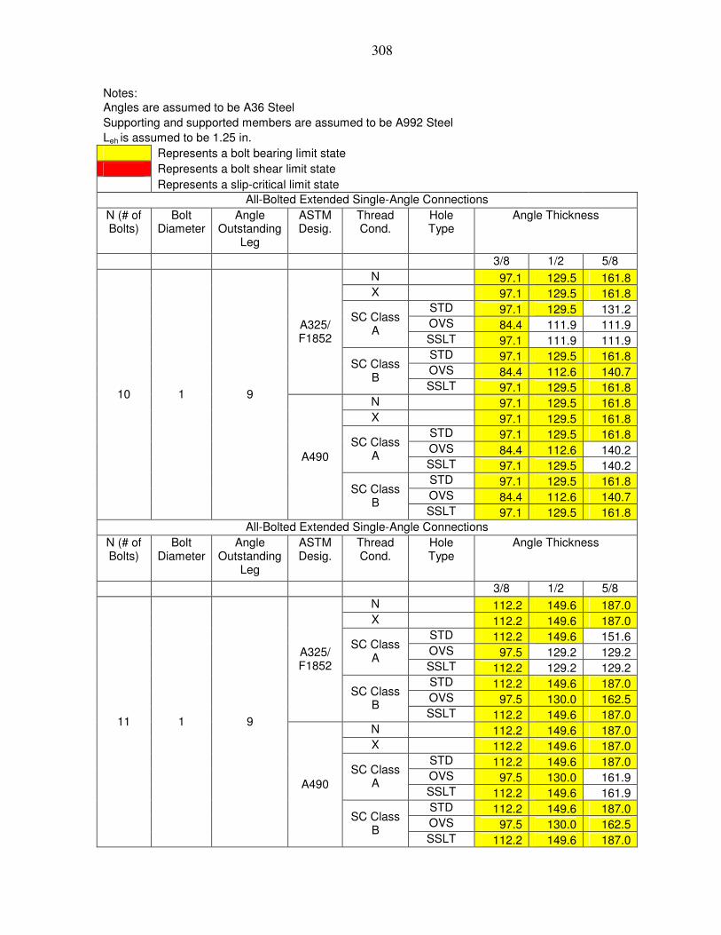
308
Notes: Angles are assumed to be A36 Steel Supporting and supported members are assumed to be A992 Steel Leh is assumed to be 1.25 in. Represents a bolt bearing limit state Represents a bolt shear limit state Represents a slip-critical limit state All-Bolted Extended Single-Angle Connections
N (# of Bolts)
Bolt Diameter
Angle Outstanding
Leg
ASTM Desig.
Thread Cond.
Hole Type
Angle Thickness
3/8 1/2 5/8 N 97.1 129.5 161.8 X 97.1 129.5 161.8 STD 97.1 129.5 131.2 OVS 84.4 111.9 111.9
SC Class A
SSLT 97.1 111.9 111.9 STD 97.1 129.5 161.8 OVS 84.4 112.6 140.7
A325/ F1852
SC Class B
SSLT 97.1 129.5 161.8 N 97.1 129.5 161.8 X 97.1 129.5 161.8 STD 97.1 129.5 161.8 OVS 84.4 112.6 140.2
SC Class A
SSLT 97.1 129.5 140.2 STD 97.1 129.5 161.8 OVS 84.4 112.6 140.7
10 1 9
A490
SC Class B
SSLT 97.1 129.5 161.8 All-Bolted Extended Single-Angle Connections
N (# of Bolts)
Bolt Diameter
Angle Outstanding
Leg
ASTM Desig.
Thread Cond.
Hole Type
Angle Thickness
3/8 1/2 5/8 N 112.2 149.6 187.0 X 112.2 149.6 187.0 STD 112.2 149.6 151.6 OVS 97.5 129.2 129.2
SC Class A
SSLT 112.2 129.2 129.2 STD 112.2 149.6 187.0 OVS 97.5 130.0 162.5
A325/ F1852
SC Class B
SSLT 112.2 149.6 187.0 N 112.2 149.6 187.0 X 112.2 149.6 187.0 STD 112.2 149.6 187.0 OVS 97.5 130.0 161.9
SC Class A
SSLT 112.2 149.6 161.9 STD 112.2 149.6 187.0 OVS 97.5 130.0 162.5
11 1 9
A490
SC Class B
SSLT 112.2 149.6 187.0

309
Notes: Angles are assumed to be A36 Steel Supporting and supported members are assumed to be A992 Steel Leh is assumed to be 1.25 in. Represents a bolt bearing limit state Represents a bolt shear limit state Represents a slip-critical limit state All-Bolted Extended Single-Angle Connections
N (# of Bolts)
Bolt Diameter
Angle Outstanding
Leg
ASTM Desig.
Thread Cond.
Hole Type
Angle Thickness
3/8 1/2 5/8 N 127.4 169.8 212.3 X 127.4 169.8 212.3 STD 127.4 169.8 172.1 OVS 110.7 146.7 146.7
SC Class A
SSLT 127.4 146.7 146.7 STD 127.4 169.8 212.3 OVS 110.7 147.6 184.5
A325/ F1852
SC Class B
SSLT 127.4 169.8 212.3 N 127.4 169.8 212.3 X 127.4 169.8 212.3 STD 127.4 169.8 212.3 OVS 110.7 147.6 183.9
SC Class A
SSLT 127.4 169.8 183.9 STD 127.4 169.8 212.3 OVS 110.7 147.6 184.5
12 1 9
A490
SC Class B
SSLT 127.4 169.8 212.3

310
APPENDIX J 3/4-INCH DIAMETER ALL-BOLTED A992 STEEL SINGLE ANGLE
CONNECTIONS
The tables given in Appendix J are all-bolted single angle connections. The angles
are A992 angles using either A325/F1852 or A490 3/4-inch diameter bolts.

311
Notes: Angles are assumed to be A992 Steel Supporting and supported members are assumed to be A992 Steel Leh is assumed to be 1.25 in. Represents a bolt bearing limit state Represents a bolt shear limit state Represents a slip-critical limit state All-Bolted Extended Single-Angle Connections
N (# of Bolts)
Bolt Diameter
Angle Outstanding
Leg
ASTM Desig.
Thread Condition
Hole Type
Angle Thickness
3/8 1/2 5/8 N 8.6 8.6 8.6 X 10.0 10.8 10.8 STD 5.6 5.6 5.6 OVS 4.8 4.8 4.8
SC Class A
SSLT 4.8 4.8 4.8 STD 8.6 8.6 8.6 OVS 7.3 7.3 7.3
A325/ F1852
SC Class B
SSLT 7.3 7.3 7.3 N 10.0 10.8 10.8 X 10.0 13.4 13.5 STD 7.1 7.1 7.1 OVS 6.0 6.0 6.0
SC Class A
SSLT 6.0 6.0 6.0 STD 10.0 10.8 10.8 OVS 9.2 9.2 9.2
2 3/4 6
A490
SC Class B
SSLT 9.2 9.2 9.2 All-Bolted Extended Single-Angle Connections
N (# of Bolts)
Bolt Diameter
Angle Outstanding
Leg
ASTM Desig.
Thread Condition
Hole Type
Angle Thickness
3/8 1/2 5/8 N 19.3 19.3 19.3 X 22.5 24.1 24.1 STD 12.6 12.6 12.6 OVS 10.8 10.8 10.8
SC Class A
SSLT 10.8 10.8 10.8 STD 19.2 19.2 19.2 OVS 16.4 16.4 16.4
A325/ F1852
SC Class B
SSLT 16.4 16.4 16.4 N 22.5 24.1 24.1 X 22.5 29.9 30.2 STD 15.9 15.9 15.9 OVS 13.5 13.5 13.5
SC Class A
SSLT 13.5 13.5 13.5 STD 22.5 24.1 24.1 OVS 20.5 20.5 20.5
3 3/4 6
A490
SC Class B
SSLT 20.5 20.5 20.5

312
Notes: Angles are assumed to be A992 Steel Supporting and supported members are assumed to be A992 Steel Leh is assumed to be 1.25 in. Represents a bolt bearing limit state Represents a bolt shear limit state Represents a slip-critical limit state All-Bolted Extended Single-Angle Connections
N (# of Bolts)
Bolt Diameter
Angle Outstanding
Leg
ASTM Desig.
Thread Condition
Hole Type
Angle Thickness
3/8 1/2 5/8 N 33.4 33.4 33.4 X 38.9 41.7 41.7 STD 21.8 21.8 21.8 OVS 18.6 18.6 18.6
SC Class A
SSLT 18.6 18.6 18.6 STD 33.2 33.2 33.2 OVS 28.3 28.3 28.3
A325/ F1852
SC Class B
SSLT 28.3 28.3 28.3 N 38.9 41.7 41.7 X 38.9 51.8 52.2 STD 27.5 27.5 27.5 OVS 23.3 23.3 23.3
SC Class A
SSLT 23.3 23.3 23.3 STD 38.9 41.8 41.8 OVS 35.4 35.4 35.4
4 3/4 6
A490
SC Class B
SSLT 35.4 35.4 35.4 All-Bolted Extended Single-Angle Connections
N (# of Bolts)
Bolt Diameter
Angle Outstanding
Leg
ASTM Desig.
Thread Condition
Hole Type
Angle Thickness
3/8 1/2 5/8 N 48.8 48.8 48.8 X 56.9 61.1 61.1 STD 31.9 31.9 31.9 OVS 27.3 27.3 27.3
SC Class A
SSLT 27.3 27.3 27.3 STD 48.5 48.5 48.5 OVS 41.4 41.4 41.4
A325/ F1852
SC Class B
SSLT 41.4 41.4 41.4 N 56.9 61.1 61.1 X 56.9 75.8 76.4 STD 40.2 40.2 40.2 OVS 34.1 34.1 34.1
SC Class A
SSLT 34.1 34.1 34.1 STD 56.9 61.1 61.1 OVS 51.8 51.8 51.8
5 3/4 6
A490
SC Class B
SSLT 51.8 51.8 51.8

313
Notes: Angles are assumed to be A992 Steel Supporting and supported members are assumed to be A992 Steel Leh is assumed to be 1.25 in. Represents a bolt bearing limit state Represents a bolt shear limit state Represents a slip-critical limit state All-Bolted Extended Single-Angle Connections
N (# of Bolts)
Bolt Diameter
Angle Outstanding
Leg
ASTM Desig.
Thread Condition
Hole Type
Angle Thickness
3/8 1/2 5/8 N 65.2 65.2 65.2 X 76.0 81.6 81.6 STD 42.7 42.7 42.7 OVS 36.4 36.4 36.4
SC Class A
SSLT 36.4 36.4 36.4 STD 64.9 64.9 64.9 OVS 55.4 55.4 55.4
A325/ F1852
SC Class B
SSLT 55.4 55.4 55.4 N 76.0 81.6 81.6 X 76.0 101.3 102.2 STD 53.7 53.7 53.7 OVS 45.5 45.5 45.5
SC Class A
SSLT 45.5 45.5 45.5 STD 76.0 81.7 81.7 OVS 69.2 69.2 69.2
6 3/4 6
A490
SC Class B
SSLT 69.2 69.2 69.2 All-Bolted Extended Single-Angle Connections
N (# of Bolts)
Bolt Diameter
Angle Outstanding
Leg
ASTM Desig.
Thread Condition
Hole Type
Angle Thickness
3/8 1/2 5/8 N 82.4 82.4 82.4 X 96.1 103.2 103.2 STD 53.9 53.9 53.9 OVS 46.0 46.0 46.0
SC Class A
SSLT 46.0 46.0 46.0 STD 82.0 82.0 82.0 OVS 70.0 70.0 70.0
A325/ F1852
SC Class B
SSLT 70.0 70.0 70.0 N 96.1 103.2 103.2 X 96.1 128.1 129.1 STD 67.9 67.9 67.9 OVS 57.6 57.6 57.6
SC Class A
SSLT 57.6 57.6 57.6 STD 96.1 103.2 103.2 OVS 87.5 87.5 87.5
7 3/4 6
A490
SC Class B
SSLT 87.5 87.5 87.5

314
Notes: Angles are assumed to be A992 Steel Supporting and supported members are assumed to be A992 Steel Leh is assumed to be 1.25 in. Represents a bolt bearing limit state Represents a bolt shear limit state Represents a slip-critical limit state All-Bolted Extended Single-Angle Connections
N (# of Bolts)
Bolt Diameter
Angle Outstanding
Leg
ASTM Desig.
Thread Condition
Hole Type
Angle Thickness
3/8 1/2 5/8 N 99.5 99.5 99.5 X 115.9 124.5 124.5 STD 65.1 65.1 65.1 OVS 55.6 55.6 55.6
SC Class A
SSLT 55.6 55.6 55.6 STD 98.9 98.9 98.9 OVS 84.5 84.5 84.5
A325/ F1852
SC Class B
SSLT 84.5 84.5 84.5 N 115.9 124.5 124.5 X 115.9 154.6 155.8 STD 82.0 82.0 82.0 OVS 69.5 69.5 69.5
SC Class A
SSLT 69.5 69.5 69.5 STD 115.9 124.6 124.6 OVS 105.6 105.6 105.6
8 3/4 6
A490
SC Class B
SSLT 105.6 105.6 105.6 All-Bolted Extended Single-Angle Connections
N (# of Bolts)
Bolt Diameter
Angle Outstanding
Leg
ASTM Desig.
Thread Condition
Hole Type
Angle Thickness
3/8 1/2 5/8 N 116.8 116.8 116.8 X 136.1 146.2 146.2 STD 76.4 76.4 76.4 OVS 65.2 65.2 65.2
SC Class A
SSLT 65.2 65.2 65.2 STD 116.1 116.1 116.1 OVS 99.1 99.1 99.1
A325/ F1852
SC Class B
SSLT 99.1 99.1 99.1 N 136.1 146.2 146.2 X 136.1 181.4 182.9 STD 96.2 96.2 96.2 OVS 81.5 81.5 81.5
SC Class A
SSLT 81.5 81.5 81.5 STD 136.1 146.3 146.3 OVS 123.9 123.9 123.9
9 3/4 6
A490
SC Class B
SSLT 123.9 123.9 123.9

315
Notes: Angles are assumed to be A992 Steel Supporting and supported members are assumed to be A992 Steel Leh is assumed to be 1.25 in. Represents a bolt bearing limit state Represents a bolt shear limit state Represents a slip-critical limit state All-Bolted Extended Single-Angle Connections
N (# of Bolts)
Bolt Diameter
Angle Outstanding
Leg
ASTM Desig.
Thread Condition
Hole Type
Angle Thickness
3/8 1/2 5/8 N 133.9 133.9 133.9 X 156.0 167.6 167.6 STD 87.6 87.6 87.6 OVS 74.8 74.8 74.8
SC Class A
SSLT 74.8 74.8 74.8 STD 133.1 133.1 133.1 OVS 113.6 113.6 113.6
A325/ F1852
SC Class B
SSLT 113.6 113.6 113.6 N 156.0 167.6 167.6 X 156.0 208.0 209.7 STD 110.3 110.3 110.3 OVS 93.5 93.5 93.5
SC Class A
SSLT 93.5 93.5 93.5 STD 156.0 167.7 167.7 OVS 142.1 142.1 142.1
10 3/4 6
A490
SC Class B
SSLT 142.1 142.1 142.1 All-Bolted Extended Single-Angle Connections
N (# of Bolts)
Bolt Diameter
Angle Outstanding
Leg
ASTM Desig.
Thread Condition
Hole Type
Angle Thickness
3/8 1/2 5/8 N 151.0 151.0 151.0 X 175.9 189.0 189.0 STD 98.7 98.7 98.7 OVS 84.3 84.3 84.3
SC Class A
SSLT 84.3 84.3 84.3 STD 150.1 150.1 150.1 OVS 128.2 128.2 128.2
A325/ F1852
SC Class B
SSLT 128.2 128.2 128.2 N 175.9 189.0 189.0 X 175.9 234.5 236.4 STD 124.4 124.4 124.4 OVS 105.4 105.4 105.4
SC Class A
SSLT 105.4 105.4 105.4 STD 175.9 189.1 189.1 OVS 160.2 160.2 160.2
11 3/4 6
A490
SC Class B
SSLT 160.2 160.2 160.2
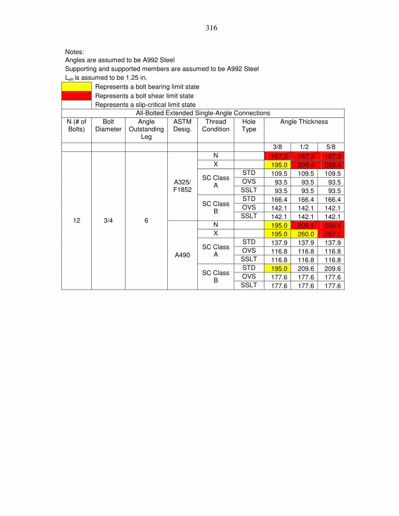
316
Notes: Angles are assumed to be A992 Steel Supporting and supported members are assumed to be A992 Steel Leh is assumed to be 1.25 in. Represents a bolt bearing limit state Represents a bolt shear limit state Represents a slip-critical limit state All-Bolted Extended Single-Angle Connections
N (# of Bolts)
Bolt Diameter
Angle Outstanding
Leg
ASTM Desig.
Thread Condition
Hole Type
Angle Thickness
3/8 1/2 5/8 N 167.3 167.3 167.3 X 195.0 209.4 209.4 STD 109.5 109.5 109.5 OVS 93.5 93.5 93.5
SC Class A
SSLT 93.5 93.5 93.5 STD 166.4 166.4 166.4 OVS 142.1 142.1 142.1
A325/ F1852
SC Class B
SSLT 142.1 142.1 142.1 N 195.0 209.4 209.4 X 195.0 260.0 262.1 STD 137.9 137.9 137.9 OVS 116.8 116.8 116.8
SC Class A
SSLT 116.8 116.8 116.8 STD 195.0 209.6 209.6 OVS 177.6 177.6 177.6
12 3/4 6
A490
SC Class B
SSLT 177.6 177.6 177.6

317
Notes: Angles are assumed to be A992 Steel Supporting and supported members are assumed to be A992 Steel Leh is assumed to be 1.25 in. Represents a bolt bearing limit state Represents a bolt shear limit state Represents a slip-critical limit state All-Bolted Extended Single-Angle Connections
N (# of Bolts)
Bolt Diameter
Angle Outstanding
Leg
ASTM Desig.
Thread Cond.
Hole Type
Angle Thickness
3/8 1/2 5/8 N 8.0 8.0 8.0 X 9.3 10.0 10.0 STD 5.2 5.2 5.2 OVS 4.4 4.4 4.4
SC Class A
SSLT 4.4 4.4 4.4 STD 7.9 7.9 7.9 OVS 6.7 6.7 6.7
A325/ F1852
SC Class B
SSLT 6.7 6.7 6.7 N 9.3 10.0 10.0 X 9.3 12.4 12.5 STD 6.6 6.6 6.6 OVS 5.6 5.6 5.6
SC Class A
SSLT 5.6 5.6 5.6 STD 9.3 10.0 10.0 OVS 8.4 8.4 8.4
2 3/4 7
A490
SC Class B
SSLT 8.4 8.4 8.4 All-Bolted Extended Single-Angle Connections
N (# of Bolts)
Bolt Diameter
Angle Outstanding
Leg
ASTM Desig.
Thread Cond.
Hole Type
Angle Thickness
3/8 1/2 5/8 N 16.1 16.1 16.1 X 18.8 20.2 20.2 STD 10.6 10.6 10.6 OVS 9.0 9.0 9.0
SC Class A
SSLT 9.0 9.0 9.0 STD 16.0 16.0 16.0 OVS 13.7 13.7 13.7
A325/ F1852
SC Class B
SSLT 13.7 13.7 13.7 N 18.8 20.2 20.2 X 18.8 25.1 25.3 STD 13.3 13.3 13.3 OVS 11.3 11.3 11.3
SC Class A
SSLT 11.3 11.3 11.3 STD 18.8 20.2 20.2 OVS 17.1 17.1 17.1
3 3/4 7
A490
SC Class B
SSLT 17.1 17.1 17.1

318
Notes: Angles are assumed to be A992 Steel Supporting and supported members are assumed to be A992 Steel Leh is assumed to be 1.25 in. Represents a bolt bearing limit state Represents a bolt shear limit state Represents a slip-critical limit state All-Bolted Extended Single-Angle Connections
N (# of Bolts)
Bolt Diameter
Angle Outstanding
Leg
ASTM Desig.
Thread Cond.
Hole Type
Angle Thickness
3/8 1/2 5/8 N 29.0 29.0 29.0 X 33.8 36.3 36.3 STD 19.0 19.0 19.0 OVS 16.2 16.2 16.2
SC Class A
SSLT 16.2 16.2 16.2 STD 28.8 28.8 28.8 OVS 24.6 24.6 24.6
A325/ F1852
SC Class B
SSLT 24.6 24.6 24.6 N 33.8 36.3 36.3 X 33.8 45.0 45.4 STD 23.9 23.9 23.9 OVS 20.2 20.2 20.2
SC Class A
SSLT 20.2 20.2 20.2 STD 33.8 36.3 36.3 OVS 30.7 30.7 30.7
4 3/4 7
A490
SC Class B
SSLT 30.7 30.7 30.7 All-Bolted Extended Single-Angle Connections
N (# of Bolts)
Bolt Diameter
Angle Outstanding
Leg
ASTM Desig.
Thread Cond.
Hole Type
Angle Thickness
3/8 1/2 5/8 N 42.7 42.7 42.7 X 49.7 53.4 53.4 STD 27.9 27.9 27.9 OVS 23.8 23.8 23.8
SC Class A
SSLT 23.8 23.8 23.8 STD 42.4 42.4 42.4 OVS 36.2 36.2 36.2
A325/ F1852
SC Class B
SSLT 36.2 36.2 36.2 N 49.7 53.4 53.4 X 49.7 66.3 66.8 STD 35.1 35.1 35.1 OVS 29.8 29.8 29.8
SC Class A
SSLT 29.8 29.8 29.8 STD 49.7 53.4 53.4 OVS 45.3 45.3 45.3
5 3/4 7
A490
SC Class B
SSLT 45.3 45.3 45.3

319
Notes: Angles are assumed to be A992 Steel Supporting and supported members are assumed to be A992 Steel Leh is assumed to be 1.25 in. Represents a bolt bearing limit state Represents a bolt shear limit state Represents a slip-critical limit state All-Bolted Extended Single-Angle Connections
N (# of Bolts)
Bolt Diameter
Angle Outstanding
Leg
ASTM Desig.
Thread Cond.
Hole Type
Angle Thickness
3/8 1/2 5/8 N 58.2 58.2 58.2 X 67.8 72.8 72.8 STD 38.0 38.0 38.0 OVS 32.5 32.5 32.5
SC Class A
SSLT 32.5 32.5 32.5 STD 57.8 57.8 57.8 OVS 49.4 49.4 49.4
A325/ F1852
SC Class B
SSLT 49.4 49.4 49.4 N 67.8 72.8 72.8 X 67.8 90.3 91.1 STD 47.9 47.9 47.9 OVS 40.6 40.6 40.6
SC Class A
SSLT 40.6 40.6 40.6 STD 67.8 72.8 72.8 OVS 61.7 61.7 61.7
6 3/4 7
A490
SC Class B
SSLT 61.7 61.7 61.7 All-Bolted Extended Single-Angle Connections
N (# of Bolts)
Bolt Diameter
Angle Outstanding
Leg
ASTM Desig.
Thread Cond.
Hole Type
Angle Thickness
3/8 1/2 5/8 N 74.6 74.6 74.6 X 86.9 93.3 93.3 STD 48.8 48.8 48.8 OVS 41.6 41.6 41.6
SC Class A
SSLT 41.6 41.6 41.6 STD 74.1 74.1 74.1 OVS 63.3 63.3 63.3
A325/ F1852
SC Class B
SSLT 63.3 63.3 63.3 N 86.9 93.3 93.3 X 86.9 115.8 116.8 STD 61.4 61.4 61.4 OVS 52.1 52.1 52.1
SC Class A
SSLT 52.1 52.1 52.1 STD 86.9 93.4 93.4 OVS 79.1 79.1 79.1
7 3/4 7
A490
SC Class B
SSLT 79.1 79.1 79.1
320
Notes: Angles are assumed to be A992 Steel Supporting and supported members are assumed to be A992 Steel Leh is assumed to be 1.25 in. Represents a bolt bearing limit state Represents a bolt shear limit state Represents a slip-critical limit state All-Bolted Extended Single-Angle Connections
N (# of Bolts)
Bolt Diameter
Angle Outstanding
Leg
ASTM Desig.
Thread Cond.
Hole Type
Angle Thickness
3/8 1/2 5/8 N 91.5 91.5 91.5 X 106.6 114.5 114.5 STD 59.9 59.9 59.9 OVS 51.1 51.1 51.1
SC Class A
SSLT 51.1 51.1 51.1 STD 91.0 91.0 91.0 OVS 77.7 77.7 77.7
A325/ F1852
SC Class B
SSLT 77.7 77.7 77.7 N 106.6 114.5 114.5 X 106.6 142.1 143.3 STD 75.4 75.4 75.4 OVS 63.9 63.9 63.9
SC Class A
SSLT 63.9 63.9 63.9 STD 106.6 114.6 114.6 OVS 97.1 97.1 97.1
8 3/4 7
A490
SC Class B
SSLT 97.1 97.1 97.1 All-Bolted Extended Single-Angle Connections
N (# of Bolts)
Bolt Diameter
Angle Outstanding
Leg
ASTM Desig.
Thread Cond.
Hole Type
Angle Thickness
3/8 1/2 5/8 N 108.6 108.6 108.6 X 126.5 135.9 135.9 STD 71.0 71.0 71.0 OVS 60.7 60.7 60.7
SC Class A
SSLT 60.7 60.7 60.7 STD 108.0 108.0 108.0 OVS 92.2 92.2 92.2
A325/ F1852
SC Class B
SSLT 92.2 92.2 92.2 N 126.5 135.9 135.9 X 126.5 168.7 170.1 STD 89.5 89.5 89.5 OVS 75.8 75.8 75.8
SC Class A
SSLT 75.8 75.8 75.8 STD 126.5 136.0 136.0 OVS 115.2 115.2 115.2
9 3/4 7
A490
SC Class B
SSLT 115.2 115.2 115.2

321
Notes: Angles are assumed to be A992 Steel Supporting and supported members are assumed to be A992 Steel Leh is assumed to be 1.25 in. Represents a bolt bearing limit state Represents a bolt shear limit state Represents a slip-critical limit state All-Bolted Extended Single-Angle Connections
N (# of Bolts)
Bolt Diameter
Angle Outstanding
Leg
ASTM Desig.
Thread Cond.
Hole Type
Angle Thickness
3/8 1/2 5/8 N 125.9 125.9 125.9 X 146.7 157.6 157.6 STD 82.3 82.3 82.3 OVS 70.3 70.3 70.3
SC Class A
SSLT 70.3 70.3 70.3 STD 125.2 125.2 125.2 OVS 106.9 106.9 106.9
A325/ F1852
SC Class B
SSLT 106.9 106.9 106.9 N 146.7 157.6 157.6 X 146.7 195.6 197.1 STD 103.7 103.7 103.7 OVS 87.9 87.9 87.9
SC Class A
SSLT 87.9 87.9 87.9 STD 146.7 157.7 157.7 OVS 133.6 133.6 133.6
10 3/4 7
A490
SC Class B
SSLT 133.6 133.6 133.6 All-Bolted Extended Single-Angle Connections
N (# of Bolts)
Bolt Diameter
Angle Outstanding
Leg
ASTM Desig.
Thread Cond.
Hole Type
Angle Thickness
3/8 1/2 5/8 N 144.3 144.3 144.3 X 168.1 180.5 180.5 STD 94.4 94.4 94.4 OVS 80.6 80.6 80.6
SC Class A
SSLT 80.6 80.6 80.6 STD 143.4 143.4 143.4 OVS 122.5 122.5 122.5
A325/ F1852
SC Class B
SSLT 122.5 122.5 122.5 N 168.1 180.5 180.5 X 168.1 224.1 225.9 STD 118.8 118.8 118.8 OVS 100.7 100.7 100.7
SC Class A
SSLT 100.7 100.7 100.7 STD 168.1 180.7 180.7 OVS 153.1 153.1 153.1
11 3/4 7
A490
SC Class B
SSLT 153.1 153.1 153.1

322
Notes: Angles are assumed to be A992 Steel Supporting and supported members are assumed to be A992 Steel Leh is assumed to be 1.25 in. Represents a bolt bearing limit state Represents a bolt shear limit state Represents a slip-critical limit state All-Bolted Extended Single-Angle Connections
N (# of Bolts)
Bolt Diameter
Angle Outstanding
Leg
ASTM Desig.
Thread Cond.
Hole Type
Angle Thickness
3/8 1/2 5/8 N 160.1 160.1 160.1 X 186.5 200.4 200.4 STD 104.7 104.7 104.7 OVS 89.4 89.4 89.4
SC Class A
SSLT 89.4 89.4 89.4 STD 159.2 159.2 159.2 OVS 135.9 135.9 135.9
A325/ F1852
SC Class B
SSLT 135.9 135.9 135.9 N 186.5 200.4 200.4 X 186.5 248.7 250.7 STD 131.9 131.9 131.9 OVS 111.8 111.8 111.8
SC Class A
SSLT 111.8 111.8 111.8 STD 186.5 200.5 200.5 OVS 169.9 169.9 169.9
12 3/4 7
A490
SC Class B
SSLT 169.9 169.9 169.9

323
Notes: Angles are assumed to be A992 Steel Supporting and supported members are assumed to be A992 Steel Leh is assumed to be 1.25 in. Represents a bolt bearing limit state Represents a bolt shear limit state Represents a slip-critical limit state All-Bolted Extended Single-Angle Connections
N (# of Bolts)
Bolt Diameter
Angle Outstanding
Leg
ASTM Desig.
Thread Cond.
Hole Type
Angle Thickness
3/8 1/2 5/8 N 6.9 6.9 6.9 X 8.0 8.6 8.6 STD 4.5 4.5 4.5 OVS 3.8 3.8 3.8
SC Class A
SSLT 3.8 3.8 3.8 STD 6.8 6.8 6.8 OVS 5.8 5.8 5.8
A325/ F1852
SC Class B
SSLT 5.8 5.8 5.8 N 8.0 8.6 8.6 X 8.0 10.7 10.8 STD 5.7 5.7 5.7 OVS 4.8 4.8 4.8
SC Class A
SSLT 4.8 4.8 4.8 STD 8.0 8.6 8.6 OVS 7.3 7.3 7.3
2 3/4 8
A490
SC Class B
SSLT 7.3 7.3 7.3 All-Bolted Extended Single-Angle Connections
N (# of Bolts)
Bolt Diameter
Angle Outstanding
Leg
ASTM Desig.
Thread Cond.
Hole Type
Angle Thickness
3/8 1/2 5/8 N 13.9 13.9 13.9 X 16.2 17.4 17.4 STD 9.1 9.1 9.1 OVS 7.8 7.8 7.8
SC Class A
SSLT 7.8 7.8 7.8 STD 13.9 13.9 13.9 OVS 11.8 11.8 11.8
A325/ F1852
SC Class B
SSLT 11.8 11.8 11.8 N 16.2 17.4 17.4 X 16.2 21.6 21.8 STD 11.5 11.5 11.5 OVS 9.7 9.7 9.7
SC Class A
SSLT 9.7 9.7 9.7 STD 16.2 17.4 17.4 OVS 14.8 14.8 14.8
3 3/4 8
A490
SC Class B
SSLT 14.8 14.8 14.8

324
Notes: Angles are assumed to be A992 Steel Supporting and supported members are assumed to be A992 Steel Leh is assumed to be 1.25 in. Represents a bolt bearing limit state Represents a bolt shear limit state Represents a slip-critical limit state All-Bolted Extended Single-Angle Connections
N (# of Bolts)
Bolt Diameter
Angle Outstanding
Leg
ASTM Desig.
Thread Cond.
Hole Type
Angle Thickness
3/8 1/2 5/8 N 25.2 25.2 25.2 X 29.3 31.5 31.5 STD 16.5 16.5 16.5 OVS 14.1 14.1 14.1
SC Class A
SSLT 14.1 14.1 14.1 STD 25.0 25.0 25.0 OVS 21.4 21.4 21.4
A325/ F1852
SC Class B
SSLT 21.4 21.4 21.4 N 29.3 31.5 31.5 X 29.3 39.1 39.4 STD 20.7 20.7 20.7 OVS 17.6 17.6 17.6
SC Class A
SSLT 17.6 17.6 17.6 STD 29.3 31.5 31.5 OVS 26.7 26.7 26.7
4 3/4 8
A490
SC Class B
SSLT 26.7 26.7 26.7 All-Bolted Extended Single-Angle Connections
N (# of Bolts)
Bolt Diameter
Angle Outstanding
Leg
ASTM Desig.
Thread Cond.
Hole Type
Angle Thickness
3/8 1/2 5/8 N 37.9 37.9 37.9 X 44.1 47.4 47.4 STD 24.8 24.8 24.8 OVS 21.2 21.2 21.2
SC Class A
SSLT 21.2 21.2 21.2 STD 37.7 37.7 37.7 OVS 32.2 32.2 32.2
A325/ F1852
SC Class B
SSLT 32.2 32.2 32.2 N 44.1 47.4 47.4 X 44.1 58.8 59.3 STD 31.2 31.2 31.2 OVS 26.4 26.4 26.4
SC Class A
SSLT 26.4 26.4 26.4 STD 44.1 47.4 47.4 OVS 40.2 40.2 40.2
5 3/4 8
A490
SC Class B
SSLT 40.2 40.2 40.2

325
Notes: Angles are assumed to be A992 Steel Supporting and supported members are assumed to be A992 Steel Leh is assumed to be 1.25 in. Represents a bolt bearing limit state Represents a bolt shear limit state Represents a slip-critical limit state All-Bolted Extended Single-Angle Connections
N (# of Bolts)
Bolt Diameter
Angle Outstanding
Leg
ASTM Desig.
Thread Cond.
Hole Type
Angle Thickness
3/8 1/2 5/8 N 52.4 52.4 52.4 X 61.0 65.6 65.6 STD 34.3 34.3 34.3 OVS 29.3 29.3 29.3
SC Class A
SSLT 29.3 29.3 29.3 STD 52.1 52.1 52.1 OVS 44.5 44.5 44.5
A325/ F1852
SC Class B
SSLT 44.5 44.5 44.5 N 61.0 65.6 65.6 X 61.0 81.4 82.1 STD 43.2 43.2 43.2 OVS 36.6 36.6 36.6
SC Class A
SSLT 36.6 36.6 36.6 STD 61.0 65.6 65.6 OVS 55.6 55.6 55.6
6 3/4 8
A490
SC Class B
SSLT 55.6 55.6 55.6 All-Bolted Extended Single-Angle Connections
N (# of Bolts)
Bolt Diameter
Angle Outstanding
Leg
ASTM Desig.
Thread Cond.
Hole Type
Angle Thickness
3/8 1/2 5/8 N 68.0 68.0 68.0 X 79.2 85.1 85.1 STD 44.5 44.5 44.5 OVS 38.0 38.0 38.0
SC Class A
SSLT 38.0 38.0 38.0 STD 67.6 67.6 67.6 OVS 57.7 57.7 57.7
A325/ F1852
SC Class B
SSLT 57.7 57.7 57.7 N 79.2 85.1 85.1 X 79.2 105.6 106.5 STD 56.0 56.0 56.0 OVS 47.5 47.5 47.5
SC Class A
SSLT 47.5 47.5 47.5 STD 79.2 85.1 85.1 OVS 72.1 72.1 72.1
7 3/4 8
A490
SC Class B
SSLT 72.1 72.1 72.1

326
Notes: Angles are assumed to be A992 Steel Supporting and supported members are assumed to be A992 Steel Leh is assumed to be 1.25 in. Represents a bolt bearing limit state Represents a bolt shear limit state Represents a slip-critical limit state All-Bolted Extended Single-Angle Connections
N (# of Bolts)
Bolt Diameter
Angle Outstanding
Leg
ASTM Desig.
Thread Cond.
Hole Type
Angle Thickness
3/8 1/2 5/8 N 84.4 84.4 84.4 X 98.3 105.6 105.6 STD 55.2 55.2 55.2 OVS 47.1 47.1 47.1
SC Class A
SSLT 47.1 47.1 47.1 STD 83.9 83.9 83.9 OVS 71.7 71.7 71.7
A325/ F1852
SC Class B
SSLT 71.7 71.7 71.7 N 98.3 105.6 105.6 X 98.3 131.1 132.2 STD 69.5 69.5 69.5 OVS 58.9 58.9 58.9
SC Class A
SSLT 58.9 58.9 58.9 STD 98.3 105.7 105.7 OVS 89.6 89.6 89.6
8 3/4 8
A490
SC Class B
SSLT 89.6 89.6 89.6 All-Bolted Extended Single-Angle Connections
N (# of Bolts)
Bolt Diameter
Angle Outstanding
Leg
ASTM Desig.
Thread Cond.
Hole Type
Angle Thickness
3/8 1/2 5/8 N 101.2 101.2 101.2 X 117.9 126.7 126.7 STD 66.2 66.2 66.2 OVS 56.5 56.5 56.5
SC Class A
SSLT 56.5 56.5 56.5 STD 100.6 100.6 100.6 OVS 85.9 85.9 85.9
A325/ F1852
SC Class B
SSLT 85.9 85.9 85.9 N 117.9 126.7 126.7 X 117.9 157.2 158.5 STD 83.4 83.4 83.4 OVS 70.7 70.7 70.7
SC Class A
SSLT 70.7 70.7 70.7 STD 117.9 126.7 126.7 OVS 107.4 107.4 107.4
9 3/4 8
A490
SC Class B
SSLT 107.4 107.4 107.4

327
Notes: Angles are assumed to be A992 Steel Supporting and supported members are assumed to be A992 Steel Leh is assumed to be 1.25 in. Represents a bolt bearing limit state Represents a bolt shear limit state Represents a slip-critical limit state All-Bolted Extended Single-Angle Connections
N (# of Bolts)
Bolt Diameter
Angle Outstanding
Leg
ASTM Desig.
Thread Cond.
Hole Type
Angle Thickness
3/8 1/2 5/8 N 118.4 118.4 118.4 X 138.0 148.2 148.2 STD 77.5 77.5 77.5 OVS 66.1 66.1 66.1
SC Class A
SSLT 66.1 66.1 66.1 STD 117.7 117.7 117.7 OVS 100.5 100.5 100.5
A325/ F1852
SC Class B
SSLT 100.5 100.5 100.5 N 138.0 148.2 148.2 X 138.0 184.0 185.5 STD 97.6 97.6 97.6 OVS 82.7 82.7 82.7
SC Class A
SSLT 82.7 82.7 82.7 STD 138.0 148.3 148.3 OVS 125.7 125.7 125.7
10 3/4 8
A490
SC Class B
SSLT 125.7 125.7 125.7 All-Bolted Extended Single-Angle Connections
N (# of Bolts)
Bolt Diameter
Angle Outstanding
Leg
ASTM Desig.
Thread Cond.
Hole Type
Angle Thickness
3/8 1/2 5/8 N 135.6 135.6 135.6 X 158.0 169.7 169.7 STD 88.7 88.7 88.7 OVS 75.7 75.7 75.7
SC Class A
SSLT 75.7 75.7 75.7 STD 134.8 134.8 134.8 OVS 115.1 115.1 115.1
A325/ F1852
SC Class B
SSLT 115.1 115.1 115.1 N 158.0 169.7 169.7 X 158.0 210.6 212.4 STD 111.7 111.7 111.7 OVS 94.7 94.7 94.7
SC Class A
SSLT 94.7 94.7 94.7 STD 158.0 169.8 169.8 OVS 143.9 143.9 143.9
11 3/4 8
A490
SC Class B
SSLT 143.9 143.9 143.9

328
Notes: Angles are assumed to be A992 Steel Supporting and supported members are assumed to be A992 Steel Leh is assumed to be 1.25 in. Represents a bolt bearing limit state Represents a bolt shear limit state Represents a slip-critical limit state All-Bolted Extended Single-Angle Connections
N (# of Bolts)
Bolt Diameter
Angle Outstanding
Leg
ASTM Desig.
Thread Cond.
Hole Type
Angle Thickness
3/8 1/2 5/8 N 152.8 152.8 152.8 X 178.1 191.3 191.3 STD 100.0 100.0 100.0 OVS 85.4 85.4 85.4
SC Class A
SSLT 85.4 85.4 85.4 STD 151.9 151.9 151.9 OVS 129.7 129.7 129.7
A325/ F1852
SC Class B
SSLT 129.7 129.7 129.7 N 178.1 191.3 191.3 X 178.1 237.4 239.3 STD 125.9 125.9 125.9 OVS 106.7 106.7 106.7
SC Class A
SSLT 106.7 106.7 106.7 STD 178.1 191.4 191.4 OVS 162.2 162.2 162.2
12 3/4 8
A490
SC Class B
SSLT 162.2 162.2 162.2

329
Notes: Angles are assumed to be A992 Steel Supporting and supported members are assumed to be A992 Steel Leh is assumed to be 1.25 in. Represents a bolt bearing limit state Represents a bolt shear limit state Represents a slip-critical limit state All-Bolted Extended Single-Angle Connections
N (# of Bolts)
Bolt Diameter
Angle Outstanding
Leg
ASTM Desig.
Thread Cond.
Hole Type
Angle Thickness
3/8 1/2 5/8 N 5.2 5.2 5.2 X 6.0 6.5 6.5 STD 3.4 3.4 3.4 OVS 2.9 2.9 2.9
SC Class A
SSLT 2.9 2.9 2.9 STD 5.1 5.1 5.1 OVS 4.4 4.4 4.4
A325/ F1852
SC Class B
SSLT 4.4 4.4 4.4 N 6.0 6.5 6.5 X 6.0 8.0 8.1 STD 4.3 4.3 4.3 OVS 3.6 3.6 3.6
SC Class A
SSLT 3.6 3.6 3.6 STD 6.0 6.5 6.5 OVS 5.5 5.5 5.5
2 3/4 9
A490
SC Class B
SSLT 5.5 5.5 5.5 All-Bolted Extended Single-Angle Connections
N (# of Bolts)
Bolt Diameter
Angle Outstanding
Leg
ASTM Desig.
Thread Cond.
Hole Type
Angle Thickness
3/8 1/2 5/8 N 12.0 12.0 12.0 X 14.0 15.0 15.0 STD 7.9 7.9 7.9 OVS 6.7 6.7 6.7
SC Class A
SSLT 6.7 6.7 6.7 STD 11.9 11.9 11.9 OVS 10.2 10.2 10.2
A325/ F1852
SC Class B
SSLT 10.2 10.2 10.2 N 14.0 15.0 15.0 X 14.0 18.6 18.8 STD 9.9 9.9 9.9 OVS 8.4 8.4 8.4
SC Class A
SSLT 8.4 8.4 8.4 STD 14.0 15.0 15.0 OVS 12.7 12.7 12.7
3 3/4 9
A490
SC Class B
SSLT 12.7 12.7 12.7

330
Notes: Angles are assumed to be A992 Steel Supporting and supported members are assumed to be A992 Steel Leh is assumed to be 1.25 in. Represents a bolt bearing limit state Represents a bolt shear limit state Represents a slip-critical limit state All-Bolted Extended Single-Angle Connections
N (# of Bolts)
Bolt Diameter
Angle Outstanding
Leg
ASTM Desig.
Thread Cond.
Hole Type
Angle Thickness
3/8 1/2 5/8 N 22.0 22.0 22.0 X 25.6 27.5 27.5 STD 14.4 14.4 14.4 OVS 12.3 12.3 12.3
SC Class A
SSLT 12.3 12.3 12.3 STD 21.9 21.9 21.9 OVS 18.7 18.7 18.7
A325/ F1852
SC Class B
SSLT 18.7 18.7 18.7 N 25.6 27.5 27.5 X 25.6 34.1 34.4 STD 18.1 18.1 18.1 OVS 15.3 15.3 15.3
SC Class A
SSLT 15.3 15.3 15.3 STD 25.6 27.5 27.5 OVS 23.3 23.3 23.3
4 3/4 9
A490
SC Class B
SSLT 23.3 23.3 23.3 All-Bolted Extended Single-Angle Connections
N (# of Bolts)
Bolt Diameter
Angle Outstanding
Leg
ASTM Desig.
Thread Cond.
Hole Type
Angle Thickness
3/8 1/2 5/8 N 33.4 33.4 33.4 X 38.9 41.8 41.8 STD 21.8 21.8 21.8 OVS 18.6 18.6 18.6
SC Class A
SSLT 18.6 18.6 18.6 STD 33.2 33.2 33.2 OVS 28.3 28.3 28.3
A325/ F1852
SC Class B
SSLT 28.3 28.3 28.3 N 38.9 41.8 41.8 X 38.9 51.9 52.3 STD 27.5 27.5 27.5 OVS 23.3 23.3 23.3
SC Class A
SSLT 23.3 23.3 23.3 STD 38.9 41.8 41.8 OVS 35.4 35.4 35.4
5 3/4 9
A490
SC Class B
SSLT 35.4 35.4 35.4

331
Notes: Angles are assumed to be A992 Steel Supporting and supported members are assumed to be A992 Steel Leh is assumed to be 1.25 in. Represents a bolt bearing limit state Represents a bolt shear limit state Represents a slip-critical limit state All-Bolted Extended Single-Angle Connections
N (# of Bolts)
Bolt Diameter
Angle Outstanding
Leg
ASTM Desig.
Thread Cond.
Hole Type
Angle Thickness
3/8 1/2 5/8 N 46.6 46.6 46.6 X 54.3 58.3 58.3 STD 30.5 30.5 30.5 OVS 26.0 26.0 26.0
SC Class A
SSLT 26.0 26.0 26.0 STD 46.3 46.3 46.3 OVS 39.5 39.5 39.5
A325/ F1852
SC Class B
SSLT 39.5 39.5 39.5 N 54.3 58.3 58.3 X 54.3 72.4 73.0 STD 38.4 38.4 38.4 OVS 32.5 32.5 32.5
SC Class A
SSLT 32.5 32.5 32.5 STD 54.3 58.3 58.3 OVS 49.4 49.4 49.4
6 3/4 9
A490
SC Class B
SSLT 49.4 49.4 49.4 All-Bolted Extended Single-Angle Connections
N (# of Bolts)
Bolt Diameter
Angle Outstanding
Leg
ASTM Desig.
Thread Cond.
Hole Type
Angle Thickness
3/8 1/2 5/8 N 61.1 61.1 61.1 X 71.2 76.5 76.5 STD 40.0 40.0 40.0 OVS 34.1 34.1 34.1
SC Class A
SSLT 34.1 34.1 34.1 STD 60.8 60.8 60.8 OVS 51.9 51.9 51.9
A325/ F1852
SC Class B
SSLT 51.9 51.9 51.9 N 71.2 76.5 76.5 X 71.2 95.0 95.7 STD 50.4 50.4 50.4 OVS 42.7 42.7 42.7
SC Class A
SSLT 42.7 42.7 42.7 STD 71.2 76.6 76.6 OVS 64.9 64.9 64.9
7 3/4 9
A490
SC Class B
SSLT 64.9 64.9 64.9

332
Notes: Angles are assumed to be A992 Steel Supporting and supported members are assumed to be A992 Steel Leh is assumed to be 1.25 in. Represents a bolt bearing limit state Represents a bolt shear limit state Represents a slip-critical limit state All-Bolted Extended Single-Angle Connections
N (# of Bolts)
Bolt Diameter
Angle Outstanding
Leg
ASTM Desig.
Thread Cond.
Hole Type
Angle Thickness
3/8 1/2 5/8 N 76.8 76.8 76.8 X 89.4 96.1 96.1 STD 50.2 50.2 50.2 OVS 42.9 42.9 42.9
SC Class A
SSLT 42.9 42.9 42.9 STD 76.3 76.3 76.3 OVS 65.2 65.2 65.2
A325/ F1852
SC Class B
SSLT 65.2 65.2 65.2 N 89.4 96.1 96.1 X 89.4 119.2 120.2 STD 63.2 63.2 63.2 OVS 53.6 53.6 53.6
SC Class A
SSLT 53.6 53.6 53.6 STD 89.4 96.1 96.1 OVS 81.4 81.4 81.4
8 3/4 9
A490
SC Class B
SSLT 81.4 81.4 81.4 All-Bolted Extended Single-Angle Connections
N (# of Bolts)
Bolt Diameter
Angle Outstanding
Leg
ASTM Desig.
Thread Cond.
Hole Type
Angle Thickness
3/8 1/2 5/8 N 93.0 93.0 93.0 X 108.3 116.4 116.4 STD 60.8 60.8 60.8 OVS 51.9 51.9 51.9
SC Class A
SSLT 51.9 51.9 51.9 STD 92.4 92.4 92.4 OVS 78.9 78.9 78.9
A325/ F1852
SC Class B
SSLT 78.9 78.9 78.9 N 108.3 116.4 116.4 X 108.3 144.4 145.6 STD 76.6 76.6 76.6 OVS 64.9 64.9 64.9
SC Class A
SSLT 64.9 64.9 64.9 STD 108.3 116.4 116.4 OVS 98.7 98.7 98.7
9 3/4 9
A490
SC Class B
SSLT 98.7 98.7 98.7

333
Notes: Angles are assumed to be A992 Steel Supporting and supported members are assumed to be A992 Steel Leh is assumed to be 1.25 in. Represents a bolt bearing limit state Represents a bolt shear limit state Represents a slip-critical limit state All-Bolted Extended Single-Angle Connections
N (# of Bolts)
Bolt Diameter
Angle Outstanding
Leg
ASTM Desig.
Thread Cond.
Hole Type
Angle Thickness
3/8 1/2 5/8 N 109.8 109.8 109.8 X 127.9 137.4 137.4 STD 71.8 71.8 71.8 OVS 61.3 61.3 61.3
SC Class A
SSLT 61.3 61.3 61.3 STD 109.2 109.2 109.2 OVS 93.2 93.2 93.2
A325/ F1852
SC Class B
SSLT 93.2 93.2 93.2 N 127.9 137.4 137.4 X 127.9 170.6 171.9 STD 90.5 90.5 90.5 OVS 76.6 76.6 76.6
SC Class A
SSLT 76.6 76.6 76.6 STD 127.9 137.5 137.5 OVS 116.5 116.5 116.5
10 3/4 9
A490
SC Class B
SSLT 116.5 116.5 116.5 All-Bolted Extended Single-Angle Connections
N (# of Bolts)
Bolt Diameter
Angle Outstanding
Leg
ASTM Desig.
Thread Cond.
Hole Type
Angle Thickness
3/8 1/2 5/8 N 126.8 126.8 126.8 X 147.8 158.8 158.8 STD 83.0 83.0 83.0 OVS 70.8 70.8 70.8
SC Class A
SSLT 70.8 70.8 70.8 STD 126.1 126.1 126.1 OVS 107.7 107.7 107.7
A325/ F1852
SC Class B
SSLT 107.7 107.7 107.7 N 147.8 158.8 158.8 X 147.8 197.0 198.6 STD 104.5 104.5 104.5 OVS 88.6 88.6 88.6
SC Class A
SSLT 88.6 88.6 88.6 STD 147.8 158.8 158.8 OVS 134.6 134.6 134.6
11 3/4 9
A490
SC Class B
SSLT 134.6 134.6 134.6

334
Notes: Angles are assumed to be A992 Steel Supporting and supported members are assumed to be A992 Steel Leh is assumed to be 1.25 in. Represents a bolt bearing limit state Represents a bolt shear limit state Represents a slip-critical limit state All-Bolted Extended Single-Angle Connections
N (# of Bolts)
Bolt Diameter
Angle Outstanding
Leg
ASTM Desig.
Thread Cond.
Hole Type
Angle Thickness
3/8 1/2 5/8 N 144.0 144.0 144.0 X 167.8 180.2 180.2 STD 94.2 94.2 94.2 OVS 80.4 80.4 80.4
SC Class A
SSLT 80.4 80.4 80.4 STD 143.2 143.2 143.2 OVS 122.3 122.3 122.3
A325/ F1852
SC Class B
SSLT 122.3 122.3 122.3 N 167.8 180.2 180.2 X 167.8 223.7 225.5 STD 118.7 118.7 118.7 OVS 100.5 100.5 100.5
SC Class A
SSLT 100.5 100.5 100.5 STD 167.8 180.4 180.4 OVS 152.8 152.8 152.8
12 3/4 9
A490
SC Class B
SSLT 152.8 152.8 152.8

335
APPENDIX K 7/8-INCH DIAMETER ALL-BOLTED A992 STEEL SINGLE ANGLE
CONNECTIONS
The tables given in Appendix K are all-bolted single angle connections. The angles
are A992 angles using either A325/F1852 or A490 7/8-inch diameter bolts.

Notes: Angles are assumed to be A992 Steel Supporting and supported members are assumed to be A992 Steel Leh is assumed to be 1.25 in. Represents a bolt bearing limit state Represents a bolt shear limit state Represents a slip-critical limit state All-Bolted Extended Single-Angle Connections
N (# of Bolts)
Bolt Diameter
Angle Outstanding
Leg
ASTM Desig.
Thread Cond.
Hole Type
Angle Thickness
3/8 1/2 5/8 N 9.3 11.7 11.7 X 9.3 12.4 14.7 STD 7.9 7.9 7.9 OVS 6.7 6.7 6.7
SC Class A
SSLT 6.7 6.7 6.7 STD 9.3 12.0 12.0 OVS 8.5 10.2 10.2
A325/ F1852
SC Class B
SSLT 9.3 10.2 10.2 N 9.3 12.4 14.7 X 9.3 12.4 15.5 STD 9.3 9.9 9.9 OVS 8.4 8.4 8.4
SC Class A
SSLT 8.4 8.4 8.4 STD 9.3 12.4 15.1 OVS 8.5 11.4 12.8
2 7/8 6
A490
SC Class B
SSLT 9.3 12.4 12.8 All-Bolted Extended Single-Angle Connections
N (# of Bolts)
Bolt Diameter
Angle Outstanding
Leg
ASTM Desig.
Thread Cond.
Hole Type
Angle Thickness
3/8 1/2 5/8 N 20.8 26.2 26.2 X 20.8 27.7 32.9 STD 17.6 17.6 17.6 OVS 15.0 15.0 15.0
SC Class A
SSLT 15.0 15.0 15.0 STD 20.8 26.7 26.7 OVS 19.1 22.9 22.9
A325/ F1852
SC Class B
SSLT 20.8 22.9 22.9 N 20.8 27.7 32.9 X 20.8 27.7 34.6 STD 20.8 22.2 22.2 OVS 18.8 18.8 18.8
SC Class A
SSLT 18.8 18.8 18.8 STD 20.8 27.7 33.7 OVS 19.1 25.5 28.6
3 7/8 6
A490
SC Class B
SSLT 20.8 27.7 28.6

337
Notes: Angles are assumed to be A992 Steel Supporting and supported members are assumed to be A992 Steel Leh is assumed to be 1.25 in. Represents a bolt bearing limit state Represents a bolt shear limit state Represents a slip-critical limit state All-Bolted Extended Single-Angle Connections
N (# of Bolts)
Bolt Diameter
Angle Outstanding
Leg
ASTM Desig.
Thread Cond.
Hole Type
Angle Thickness
3/8 1/2 5/8 N 35.9 45.3 45.3 X 35.9 48.0 56.8 STD 30.4 30.4 30.4 OVS 26.0 26.0 26.0
SC Class A
SSLT 26.0 26.0 26.0 STD 35.9 46.2 46.2 OVS 33.0 39.5 39.5
A325/ F1852
SC Class B
SSLT 35.9 39.5 39.5 N 35.9 47.9 56.8 X 35.9 47.9 59.9 STD 35.9 38.4 38.4 OVS 32.5 32.5 32.5
SC Class A
SSLT 32.5 32.5 32.5 STD 35.9 47.9 58.3 OVS 33.0 44.0 49.4
4 7/8 6
A490
SC Class B
SSLT 35.9 47.9 49.4 All-Bolted Extended Single-Angle Connections
N (# of Bolts)
Bolt Diameter
Angle Outstanding
Leg
ASTM Desig.
Thread Cond.
Hole Type
Angle Thickness
3/8 1/2 5/8 N 52.6 66.3 66.3 X 52.6 70.2 83.2 STD 44.5 44.5 44.5 OVS 38.1 38.1 38.1
SC Class A
SSLT 38.1 38.1 38.1 STD 52.6 67.7 67.7 OVS 48.4 57.9 57.9
A325/ F1852
SC Class B
SSLT 52.6 57.9 57.9 N 52.6 70.1 83.2 X 52.6 70.1 87.7 STD 52.6 56.2 56.2 OVS 47.6 47.6 47.6
SC Class A
SSLT 47.6 47.6 47.6 STD 52.6 70.1 85.4 OVS 48.4 64.5 72.3
5 7/8 6
A490
SC Class B
SSLT 52.6 70.1 72.3

338
Notes: Angles are assumed to be A992 Steel Supporting and supported members are assumed to be A992 Steel Leh is assumed to be 1.25 in. Represents a bolt bearing limit state Represents a bolt shear limit state Represents a slip-critical limit state All-Bolted Extended Single-Angle Connections
N (# of Bolts)
Bolt Diameter
Angle Outstanding
Leg
ASTM Desig.
Thread Cond.
Hole Type
Angle Thickness
3/8 1/2 5/8 N 70.3 88.6 88.6 X 70.3 93.8 111.2 STD 59.5 59.5 59.5 OVS 50.9 50.9 50.9
SC Class A
SSLT 50.9 50.9 50.9 STD 70.3 90.4 90.4 OVS 64.6 77.3 77.3
A325/ F1852
SC Class B
SSLT 70.3 77.3 77.3 N 70.3 93.7 111.2 X 70.3 93.7 117.2 STD 70.3 75.1 75.1 OVS 63.6 63.6 63.6
SC Class A
SSLT 63.6 63.6 63.6 STD 70.3 93.7 114.1 OVS 64.6 86.2 96.7
6 7/8 6
A490
SC Class B
SSLT 70.3 93.7 96.7 All-Bolted Extended Single-Angle Connections
N (# of Bolts)
Bolt Diameter
Angle Outstanding
Leg
ASTM Desig.
Thread Cond.
Hole Type
Angle Thickness
3/8 1/2 5/8 N 88.9 112.0 112.0 X 88.9 118.6 140.5 STD 75.2 75.2 75.2 OVS 64.3 64.3 64.3
SC Class A
SSLT 64.3 64.3 64.3 STD 88.9 114.3 114.3 OVS 81.7 97.7 97.7
A325/ F1852
SC Class B
SSLT 88.9 97.7 97.7 N 88.9 118.5 140.5 X 88.9 118.5 148.1 STD 88.9 94.9 94.9 OVS 80.4 80.4 80.4
SC Class A
SSLT 80.4 80.4 80.4 STD 88.9 118.5 144.2 OVS 81.7 108.9 122.2
7 7/8 6
A490
SC Class B
SSLT 88.9 118.5 122.2

339
Notes: Angles are assumed to be A992 Steel Supporting and supported members are assumed to be A992 Steel Leh is assumed to be 1.25 in. Represents a bolt bearing limit state Represents a bolt shear limit state Represents a slip-critical limit state All-Bolted Extended Single-Angle Connections
N (# of Bolts)
Bolt Diameter
Angle Outstanding
Leg
ASTM Desig.
Thread Cond.
Hole Type
Angle Thickness
3/8 1/2 5/8 N 107.2 135.2 135.2 X 107.2 143.1 169.6 STD 90.7 90.7 90.7 OVS 77.6 77.6 77.6
SC Class A
SSLT 77.6 77.6 77.6 STD 107.2 137.9 137.9 OVS 98.6 117.9 117.9
A325/ F1852
SC Class B
SSLT 107.2 117.9 117.9 N 107.2 143.0 169.6 X 107.2 143.0 178.7 STD 107.2 114.5 114.5 OVS 97.0 97.0 97.0
SC Class A
SSLT 97.0 97.0 97.0 STD 107.2 143.0 174.1 OVS 98.6 131.4 147.4
8 7/8 6
A490
SC Class B
SSLT 107.2 143.0 147.4 All-Bolted Extended Single-Angle Connections
N (# of Bolts)
Bolt Diameter
Angle Outstanding
Leg
ASTM Desig.
Thread Cond.
Hole Type
Angle Thickness
3/8 1/2 5/8 N 125.9 158.7 158.7 X 125.9 168.0 199.0 STD 106.5 106.5 106.5 OVS 91.1 91.1 91.1
SC Class A
SSLT 91.1 91.1 91.1 STD 125.9 161.9 161.9 OVS 115.7 138.4 138.4
A325/ F1852
SC Class B
SSLT 125.9 138.4 138.4 N 125.9 167.8 199.0 X 125.9 167.8 209.8 STD 125.9 134.4 134.4 OVS 113.8 113.8 113.8
SC Class A
SSLT 113.8 113.8 113.8 STD 125.9 167.8 204.3 OVS 115.7 154.2 173.0
9 7/8 6
A490
SC Class B
SSLT 125.9 167.8 173.0

340
Notes: Angles are assumed to be A992 Steel Supporting and supported members are assumed to be A992 Steel Leh is assumed to be 1.25 in. Represents a bolt bearing limit state Represents a bolt shear limit state Represents a slip-critical limit state All-Bolted Extended Single-Angle Connections
N (# of Bolts)
Bolt Diameter
Angle Outstanding
Leg
ASTM Desig.
Thread Cond.
Hole Type
Angle Thickness
3/8 1/2 5/8 N 144.3 181.9 181.9 X 144.3 192.6 228.2 STD 122.1 122.1 122.1 OVS 104.4 104.4 104.4
SC Class A
SSLT 104.4 104.4 104.4 STD 144.3 185.6 185.6 OVS 132.6 158.7 158.7
A325/ F1852
SC Class B
SSLT 144.3 158.7 158.7 N 144.3 192.4 228.2 X 144.3 192.4 240.5 STD 144.3 154.1 154.1 OVS 130.5 130.5 130.5
SC Class A
SSLT 130.5 130.5 130.5 STD 144.3 192.4 234.2 OVS 132.6 176.8 198.4
10 7/8 6
A490
SC Class B
SSLT 144.3 192.4 198.4 All-Bolted Extended Single-Angle Connections
N (# of Bolts)
Bolt Diameter
Angle Outstanding
Leg
ASTM Desig.
Thread Cond.
Hole Type
Angle Thickness
3/8 1/2 5/8 N 162.7 205.1 205.1 X 162.7 217.2 257.3 STD 137.7 137.7 137.7 OVS 117.7 117.7 117.7
SC Class A
SSLT 117.7 117.7 117.7 STD 162.7 209.3 209.3 OVS 149.5 179.0 179.0
A325/ F1852
SC Class B
SSLT 162.7 179.0 179.0 N 162.7 217.0 257.3 X 162.7 217.0 271.2 STD 162.7 173.8 173.8 OVS 147.2 147.2 147.2
SC Class A
SSLT 147.2 147.2 147.2 STD 162.7 217.0 264.1 OVS 149.5 199.4 223.7
11 7/8 6
A490
SC Class B
SSLT 162.7 217.0 223.7

341
Notes: Angles are assumed to be A992 Steel Supporting and supported members are assumed to be A992 Steel Leh is assumed to be 1.25 in. Represents a bolt bearing limit state Represents a bolt shear limit state Represents a slip-critical limit state All-Bolted Extended Single-Angle Connections
N (# of Bolts)
Bolt Diameter
Angle Outstanding
Leg
ASTM Desig.
Thread Cond.
Hole Type
Angle Thickness
3/8 1/2 5/8 N 180.4 227.3 227.3 X 180.4 240.8 285.2 STD 152.6 152.6 152.6 OVS 130.5 130.5 130.5
SC Class A
SSLT 130.5 130.5 130.5 STD 180.4 232.0 232.0 OVS 165.8 198.4 198.4
A325/ F1852
SC Class B
SSLT 180.4 198.4 198.4 N 180.4 240.5 285.2 X 180.4 240.5 300.6 STD 180.4 192.6 192.6 OVS 163.1 163.1 163.1
SC Class A
SSLT 163.1 163.1 163.1 STD 180.4 240.5 292.8 OVS 165.8 221.0 248.0
12 7/8 6
A490
SC Class B
SSLT 180.4 240.5 248.0

342
Notes: Angles are assumed to be A992 Steel Supporting and supported members are assumed to be A992 Steel Leh is assumed to be 1.25 in. Represents a bolt bearing limit state Represents a bolt shear limit state Represents a slip-critical limit state All-Bolted Extended Single-Angle Connections
N (# of Bolts)
Bolt Diameter
Angle Outstanding
Leg
ASTM Desig.
Thread Cond.
Hole Type
Angle Thickness
3/8 1/2 5/8 N 8.6 10.8 10.8 X 8.6 11.4 13.6 STD 7.3 7.3 7.3 OVS 6.2 6.2 6.2
SC Class A
SSLT 6.2 6.2 6.2 STD 8.6 11.0 11.0 OVS 7.9 9.4 9.4
A325/ F1852
SC Class B
SSLT 8.6 9.4 9.4 N 8.6 11.4 13.6 X 8.6 11.4 14.3 STD 8.6 9.2 9.2 OVS 7.8 7.8 7.8
SC Class A
SSLT 7.8 7.8 7.8 STD 8.6 11.4 13.9 OVS 7.9 10.5 11.8
2 7/8 7
A490
SC Class B
SSLT 8.6 11.4 11.8 All-Bolted Extended Single-Angle Connections
N (# of Bolts)
Bolt Diameter
Angle Outstanding
Leg
ASTM Desig.
Thread Cond.
Hole Type
Angle Thickness
3/8 1/2 5/8 N 17.4 21.9 21.9 X 17.4 23.2 27.5 STD 14.7 14.7 14.7 OVS 12.6 12.6 12.6
SC Class A
SSLT 12.6 12.6 12.6 STD 17.4 22.4 22.4 OVS 16.0 19.1 19.1
A325/ F1852
SC Class B
SSLT 17.4 19.1 19.1 N 17.4 23.2 27.5 X 17.4 23.2 29.0 STD 17.4 18.6 18.6 OVS 15.7 15.7 15.7
SC Class A
SSLT 15.7 15.7 15.7 STD 17.4 23.2 28.2 OVS 16.0 21.3 23.9
3 7/8 7
A490
SC Class B
SSLT 17.4 23.2 23.9

343
Notes: Angles are assumed to be A992 Steel Supporting and supported members are assumed to be A992 Steel Leh is assumed to be 1.25 in. Represents a bolt bearing limit state Represents a bolt shear limit state Represents a slip-critical limit state All-Bolted Extended Single-Angle Connections
N (# of Bolts)
Bolt Diameter
Angle Outstanding
Leg
ASTM Desig.
Thread Cond.
Hole Type
Angle Thickness
3/8 1/2 5/8 N 31.2 39.4 39.4 X 31.2 41.7 49.4 STD 26.4 26.4 26.4 OVS 22.6 22.6 22.6
SC Class A
SSLT 22.6 22.6 22.6 STD 31.2 40.2 40.2 OVS 28.7 34.4 34.4
A325/ F1852
SC Class B
SSLT 31.2 34.4 34.4 N 31.2 41.6 49.4 X 31.2 41.6 52.1 STD 31.2 33.4 33.4 OVS 28.2 28.2 28.2
SC Class A
SSLT 28.2 28.2 28.2 STD 31.2 41.6 50.7 OVS 28.7 38.3 42.9
4 7/8 7
A490
SC Class B
SSLT 31.2 41.6 42.9 All-Bolted Extended Single-Angle Connections
N (# of Bolts)
Bolt Diameter
Angle Outstanding
Leg
ASTM Desig.
Thread Cond.
Hole Type
Angle Thickness
3/8 1/2 5/8 N 46.0 57.9 57.9 X 46.0 61.4 72.7 STD 38.9 38.9 38.9 OVS 33.3 33.3 33.3
SC Class A
SSLT 33.3 33.3 33.3 STD 46.0 59.1 59.1 OVS 42.2 50.6 50.6
A325/ F1852
SC Class B
SSLT 46.0 50.6 50.6 N 46.0 61.3 72.7 X 46.0 61.3 76.6 STD 46.0 49.1 49.1 OVS 41.6 41.6 41.6
SC Class A
SSLT 41.6 41.6 41.6 STD 46.0 61.3 74.6 OVS 42.2 56.3 63.2
5 7/8 7
A490
SC Class B
SSLT 46.0 61.3 63.2

344
Notes: Angles are assumed to be A992 Steel Supporting and supported members are assumed to be A992 Steel Leh is assumed to be 1.25 in. Represents a bolt bearing limit state Represents a bolt shear limit state Represents a slip-critical limit state All-Bolted Extended Single-Angle Connections
N (# of Bolts)
Bolt Diameter
Angle Outstanding
Leg
ASTM Desig.
Thread Cond.
Hole Type
Angle Thickness
3/8 1/2 5/8 N 62.7 79.0 79.0 X 62.7 83.7 99.1 STD 53.0 53.0 53.0 OVS 45.4 45.4 45.4
SC Class A
SSLT 45.4 45.4 45.4 STD 62.7 80.6 80.6 OVS 57.6 68.9 68.9
A325/ F1852
SC Class B
SSLT 62.7 68.9 68.9 N 62.7 83.6 99.1 X 62.7 83.6 104.5 STD 62.7 66.9 66.9 OVS 56.7 56.7 56.7
SC Class A
SSLT 56.7 56.7 56.7 STD 62.7 83.6 101.7 OVS 57.6 76.8 86.2
6 7/8 7
A490
SC Class B
SSLT 62.7 83.6 86.2 All-Bolted Extended Single-Angle Connections
N (# of Bolts)
Bolt Diameter
Angle Outstanding
Leg
ASTM Desig.
Thread Cond.
Hole Type
Angle Thickness
3/8 1/2 5/8 N 80.4 101.3 101.3 X 80.4 107.3 127.1 STD 68.0 68.0 68.0 OVS 58.2 58.2 58.2
SC Class A
SSLT 58.2 58.2 58.2 STD 80.4 103.4 103.4 OVS 73.9 88.4 88.4
A325/ F1852
SC Class B
SSLT 80.4 88.4 88.4 N 80.4 107.2 127.1 X 80.4 107.2 134.0 STD 80.4 85.8 85.8 OVS 72.7 72.7 72.7
SC Class A
SSLT 72.7 72.7 72.7 STD 80.4 107.2 130.5 OVS 73.9 98.5 110.5
7 7/8 7
A490
SC Class B
SSLT 80.4 107.2 110.5

345
Notes: Angles are assumed to be A992 Steel Supporting and supported members are assumed to be A992 Steel Leh is assumed to be 1.25 in. Represents a bolt bearing limit state Represents a bolt shear limit state Represents a slip-critical limit state All-Bolted Extended Single-Angle Connections
N (# of Bolts)
Bolt Diameter
Angle Outstanding
Leg
ASTM Desig.
Thread Cond.
Hole Type
Angle Thickness
3/8 1/2 5/8 N 98.6 124.3 124.3 X 98.6 131.6 156.0 STD 83.4 83.4 83.4 OVS 71.4 71.4 71.4
SC Class A
SSLT 71.4 71.4 71.4 STD 98.6 126.8 126.8 OVS 90.6 108.5 108.5
A325/ F1852
SC Class B
SSLT 98.6 108.5 108.5 N 98.6 131.5 156.0 X 98.6 131.5 164.4 STD 98.6 105.3 105.3 OVS 89.2 89.2 89.2
SC Class A
SSLT 89.2 89.2 89.2 STD 98.6 131.5 160.1 OVS 90.6 120.9 135.6
8 7/8 7
A490
SC Class B
SSLT 98.6 131.5 135.6 All-Bolted Extended Single-Angle Connections
N (# of Bolts)
Bolt Diameter
Angle Outstanding
Leg
ASTM Desig.
Thread Cond.
Hole Type
Angle Thickness
3/8 1/2 5/8 N 117.0 147.5 147.5 X 117.0 156.2 185.1 STD 99.0 99.0 99.0 OVS 84.7 84.7 84.7
SC Class A
SSLT 84.7 84.7 84.7 STD 117.0 150.5 150.5 OVS 107.6 128.7 128.7
A325/ F1852
SC Class B
SSLT 117.0 128.7 128.7 N 117.0 156.1 185.1 X 117.0 156.1 195.1 STD 117.0 125.0 125.0 OVS 105.9 105.9 105.9
SC Class A
SSLT 105.9 105.9 105.9 STD 117.0 156.1 190.0 OVS 107.6 143.4 160.9
9 7/8 7
A490
SC Class B
SSLT 117.0 156.1 160.9

346
Notes: Angles are assumed to be A992 Steel Supporting and supported members are assumed to be A992 Steel Leh is assumed to be 1.25 in. Represents a bolt bearing limit state Represents a bolt shear limit state Represents a slip-critical limit state All-Bolted Extended Single-Angle Connections
N (# of Bolts)
Bolt Diameter
Angle Outstanding
Leg
ASTM Desig.
Thread Cond.
Hole Type
Angle Thickness
3/8 1/2 5/8 N 135.7 171.0 171.0 X 135.7 181.1 214.6 STD 114.8 114.8 114.8 OVS 98.2 98.2 98.2
SC Class A
SSLT 98.2 98.2 98.2 STD 135.7 174.5 174.5 OVS 124.7 149.2 149.2
A325/ F1852
SC Class B
SSLT 135.7 149.2 149.2 N 135.7 180.9 214.6 X 135.7 180.9 226.1 STD 135.7 144.9 144.9 OVS 122.7 122.7 122.7
SC Class A
SSLT 122.7 122.7 122.7 STD 135.7 180.9 220.2 OVS 124.7 166.3 186.5
10 7/8 7
A490
SC Class B
SSLT 135.7 180.9 186.5 All-Bolted Extended Single-Angle Connections
N (# of Bolts)
Bolt Diameter
Angle Outstanding
Leg
ASTM Desig.
Thread Cond.
Hole Type
Angle Thickness
3/8 1/2 5/8 N 155.5 196.0 196.0 X 155.5 207.5 245.9 STD 131.6 131.6 131.6 OVS 112.5 112.5 112.5
SC Class A
SSLT 112.5 112.5 112.5 STD 155.5 200.0 200.0 OVS 142.9 171.0 171.0
A325/ F1852
SC Class B
SSLT 155.5 171.0 171.0 N 155.5 207.3 245.9 X 155.5 207.3 259.1 STD 155.5 166.0 166.0 OVS 140.6 140.6 140.6
SC Class A
SSLT 140.6 140.6 140.6 STD 155.5 207.3 252.4 OVS 142.9 190.5 213.7
11 7/8 7
A490
SC Class B
SSLT 155.5 207.3 213.7

347
Notes: Angles are assumed to be A992 Steel Supporting and supported members are assumed to be A992 Steel Leh is assumed to be 1.25 in. Represents a bolt bearing limit state Represents a bolt shear limit state Represents a slip-critical limit state All-Bolted Extended Single-Angle Connections
N (# of Bolts)
Bolt Diameter
Angle Outstanding
Leg
ASTM Desig.
Thread Cond.
Hole Type
Angle Thickness
3/8 1/2 5/8 N 172.6 217.5 217.5 X 172.6 230.4 272.9 STD 146.0 146.0 146.0 OVS 124.9 124.9 124.9
SC Class A
SSLT 124.9 124.9 124.9 STD 172.6 221.9 221.9 OVS 158.6 189.8 189.8
A325/ F1852
SC Class B
SSLT 172.6 189.8 189.8 N 172.6 230.1 272.9 X 172.6 230.1 287.6 STD 172.6 184.3 184.3 OVS 156.1 156.1 156.1
SC Class A
SSLT 156.1 156.1 156.1 STD 172.6 230.1 280.1 OVS 158.6 211.5 237.2
12 7/8 7
A490
SC Class B
SSLT 172.6 230.1 237.2

348
Notes: Angles are assumed to be A992 Steel Supporting and supported members are assumed to be A992 Steel Leh is assumed to be 1.25 in. Represents a bolt bearing limit state Represents a bolt shear limit state Represents a slip-critical limit state All-Bolted Extended Single-Angle Connections
N (# of Bolts)
Bolt Diameter
Angle Outstanding
Leg
ASTM Desig.
Thread Cond.
Hole Type
Angle Thickness
3/8 1/2 5/8 N 7.4 9.4 9.4 X 7.4 9.9 11.7 STD 6.3 6.3 6.3 OVS 5.4 5.4 5.4
SC Class A
SSLT 5.4 5.4 5.4 STD 7.4 9.5 9.5 OVS 6.8 8.2 8.2
A325/ F1852
SC Class B
SSLT 7.4 8.2 8.2 N 7.4 9.9 11.7 X 7.4 9.9 12.4 STD 7.4 7.9 7.9 OVS 6.7 6.7 6.7
SC Class A
SSLT 6.7 6.7 6.7 STD 7.4 9.9 12.0 OVS 6.8 9.1 10.2
2 7/8 8
A490
SC Class B
SSLT 7.4 9.9 10.2 All-Bolted Extended Single-Angle Connections
N (# of Bolts)
Bolt Diameter
Angle Outstanding
Leg
ASTM Desig.
Thread Cond.
Hole Type
Angle Thickness
3/8 1/2 5/8 N 15.0 18.9 18.9 X 15.0 20.0 23.7 STD 12.7 12.7 12.7 OVS 10.9 10.9 10.9
SC Class A
SSLT 10.9 10.9 10.9 STD 15.0 19.3 19.3 OVS 13.8 16.5 16.5
A325/ F1852
SC Class B
SSLT 15.0 16.5 16.5 N 15.0 20.0 23.7 X 15.0 20.0 25.0 STD 15.0 16.0 16.0 OVS 13.6 13.6 13.6
SC Class A
SSLT 13.6 13.6 13.6 STD 15.0 20.0 24.4 OVS 13.8 18.4 20.6
3 7/8 8
A490
SC Class B
SSLT 15.0 20.0 20.6

349
Notes: Angles are assumed to be A992 Steel Supporting and supported members are assumed to be A992 Steel Leh is assumed to be 1.25 in. Represents a bolt bearing limit state Represents a bolt shear limit state Represents a slip-critical limit state All-Bolted Extended Single-Angle Connections
N (# of Bolts)
Bolt Diameter
Angle Outstanding
Leg
ASTM Desig.
Thread Cond.
Hole Type
Angle Thickness
3/8 1/2 5/8 N 27.1 34.2 34.2 X 27.1 36.2 42.9 STD 22.9 22.9 22.9 OVS 19.6 19.6 19.6
SC Class A
SSLT 19.6 19.6 19.6 STD 27.1 34.9 34.9 OVS 24.9 29.8 29.8
A325/ F1852
SC Class B
SSLT 27.1 29.8 29.8 N 27.1 36.2 42.9 X 27.1 36.2 45.2 STD 27.1 29.0 29.0 OVS 24.5 24.5 24.5
SC Class A
SSLT 24.5 24.5 24.5 STD 27.1 36.2 44.0 OVS 24.9 33.2 37.3
4 7/8 8
A490
SC Class B
SSLT 27.1 36.2 37.3 All-Bolted Extended Single-Angle Connections
N (# of Bolts)
Bolt Diameter
Angle Outstanding
Leg
ASTM Desig.
Thread Cond.
Hole Type
Angle Thickness
3/8 1/2 5/8 N 40.8 51.5 51.5 X 40.8 54.5 64.6 STD 34.5 34.5 34.5 OVS 29.5 29.5 29.5
SC Class A
SSLT 29.5 29.5 29.5 STD 40.8 52.5 52.5 OVS 37.5 44.9 44.9
A325/ F1852
SC Class B
SSLT 40.8 44.9 44.9 N 40.8 54.4 64.6 X 40.8 54.4 68.0 STD 40.8 43.6 43.6 OVS 36.9 36.9 36.9
SC Class A
SSLT 36.9 36.9 36.9 STD 40.8 54.4 66.3 OVS 37.5 50.0 56.1
5 7/8 8
A490
SC Class B
SSLT 40.8 54.4 56.1
350
Notes: Angles are assumed to be A992 Steel Supporting and supported members are assumed to be A992 Steel Leh is assumed to be 1.25 in. Represents a bolt bearing limit state Represents a bolt shear limit state Represents a slip-critical limit state All-Bolted Extended Single-Angle Connections
N (# of Bolts)
Bolt Diameter
Angle Outstanding
Leg
ASTM Desig.
Thread Cond.
Hole Type
Angle Thickness
3/8 1/2 5/8 N 56.5 71.2 71.2 X 56.5 75.4 89.3 STD 47.8 47.8 47.8 OVS 40.9 40.9 40.9
SC Class A
SSLT 40.9 40.9 40.9 STD 56.5 72.6 72.6 OVS 51.9 62.1 62.1
A325/ F1852
SC Class B
SSLT 56.5 62.1 62.1 N 56.5 75.3 89.3 X 56.5 75.3 94.1 STD 56.5 60.3 60.3 OVS 51.1 51.1 51.1
SC Class A
SSLT 51.1 51.1 51.1 STD 56.5 75.3 91.7 OVS 51.9 69.2 77.6
6 7/8 8
A490
SC Class B
SSLT 56.5 75.3 77.6 All-Bolted Extended Single-Angle Connections
N (# of Bolts)
Bolt Diameter
Angle Outstanding
Leg
ASTM Desig.
Thread Cond.
Hole Type
Angle Thickness
3/8 1/2 5/8 N 73.3 92.3 92.3 X 73.3 97.8 115.9 STD 62.0 62.0 62.0 OVS 53.0 53.0 53.0
SC Class A
SSLT 53.0 53.0 53.0 STD 73.3 94.2 94.2 OVS 67.3 80.6 80.6
A325/ F1852
SC Class B
SSLT 73.3 80.6 80.6 N 73.3 97.7 115.9 X 73.3 97.7 122.1 STD 73.3 78.2 78.2 OVS 66.3 66.3 66.3
SC Class A
SSLT 66.3 66.3 66.3 STD 73.3 97.7 118.9 OVS 67.3 89.8 100.7
7 7/8 8
A490
SC Class B
SSLT 73.3 97.7 100.7

351
Notes: Angles are assumed to be A992 Steel Supporting and supported members are assumed to be A992 Steel Leh is assumed to be 1.25 in. Represents a bolt bearing limit state Represents a bolt shear limit state Represents a slip-critical limit state All-Bolted Extended Single-Angle Connections
N (# of Bolts)
Bolt Diameter
Angle Outstanding
Leg
ASTM Desig.
Thread Cond.
Hole Type
Angle Thickness
3/8 1/2 5/8 N 91.0 114.7 114.7 X 91.0 121.4 143.9 STD 77.0 77.0 77.0 OVS 65.8 65.8 65.8
SC Class A
SSLT 65.8 65.8 65.8 STD 91.0 117.0 117.0 OVS 83.6 100.1 100.1
A325/ F1852
SC Class B
SSLT 91.0 100.1 100.1 N 91.0 121.3 143.9 X 91.0 121.3 151.6 STD 91.0 97.1 97.1 OVS 82.3 82.3 82.3
SC Class A
SSLT 82.3 82.3 82.3 STD 91.0 121.3 147.7 OVS 83.6 111.5 125.1
8 7/8 8
A490
SC Class B
SSLT 91.0 121.3 125.1 All-Bolted Extended Single-Angle Connections
N (# of Bolts)
Bolt Diameter
Angle Outstanding
Leg
ASTM Desig.
Thread Cond.
Hole Type
Angle Thickness
3/8 1/2 5/8 N 109.1 137.5 137.5 X 109.1 145.6 172.5 STD 92.3 92.3 92.3 OVS 78.9 78.9 78.9
SC Class A
SSLT 78.9 78.9 78.9 STD 109.1 140.3 140.3 OVS 100.2 120.0 120.0
A325/ F1852
SC Class B
SSLT 109.1 120.0 120.0 N 109.1 145.4 172.5 X 109.1 145.4 181.8 STD 109.1 116.5 116.5 OVS 98.7 98.7 98.7
SC Class A
SSLT 98.7 98.7 98.7 STD 109.1 145.4 177.0 OVS 100.2 133.7 150.0
9 7/8 8
A490
SC Class B
SSLT 109.1 145.4 150.0

352
Notes: Angles are assumed to be A992 Steel Supporting and supported members are assumed to be A992 Steel Leh is assumed to be 1.25 in. Represents a bolt bearing limit state Represents a bolt shear limit state Represents a slip-critical limit state All-Bolted Extended Single-Angle Connections
N (# of Bolts)
Bolt Diameter
Angle Outstanding
Leg
ASTM Desig.
Thread Cond.
Hole Type
Angle Thickness
3/8 1/2 5/8 N 127.6 160.9 160.9 X 127.6 170.4 201.8 STD 108.0 108.0 108.0 OVS 92.4 92.4 92.4
SC Class A
SSLT 92.4 92.4 92.4 STD 127.6 164.2 164.2 OVS 117.3 140.4 140.4
A325/ F1852
SC Class B
SSLT 127.6 140.4 140.4 N 127.6 170.2 201.8 X 127.6 170.2 212.7 STD 127.6 136.3 136.3 OVS 115.4 115.4 115.4
SC Class A
SSLT 115.4 115.4 115.4 STD 127.6 170.2 207.2 OVS 117.3 156.4 175.5
10 7/8 8
A490
SC Class B
SSLT 127.6 170.2 175.5 All-Bolted Extended Single-Angle Connections
N (# of Bolts)
Bolt Diameter
Angle Outstanding
Leg
ASTM Desig.
Thread Cond.
Hole Type
Angle Thickness
3/8 1/2 5/8 N 146.2 184.2 184.2 X 146.2 195.1 231.1 STD 123.7 123.7 123.7 OVS 105.8 105.8 105.8
SC Class A
SSLT 105.8 105.8 105.8 STD 146.2 188.0 188.0 OVS 134.3 160.7 160.7
A325/ F1852
SC Class B
SSLT 146.2 160.7 160.7 N 146.2 194.9 231.1 X 146.2 194.9 243.6 STD 146.2 156.1 156.1 OVS 132.2 132.2 132.2
SC Class A
SSLT 132.2 132.2 132.2 STD 146.2 194.9 237.2 OVS 134.3 179.1 200.9
11 7/8 8
A490
SC Class B
SSLT 146.2 194.9 200.9

353
Notes: Angles are assumed to be A992 Steel Supporting and supported members are assumed to be A992 Steel Leh is assumed to be 1.25 in. Represents a bolt bearing limit state Represents a bolt shear limit state Represents a slip-critical limit state All-Bolted Extended Single-Angle Connections
N (# of Bolts)
Bolt Diameter
Angle Outstanding
Leg
ASTM Desig.
Thread Cond.
Hole Type
Angle Thickness
3/8 1/2 5/8 N 164.7 207.6 207.6 X 164.7 219.9 260.5 STD 139.4 139.4 139.4 OVS 119.2 119.2 119.2
SC Class A
SSLT 119.2 119.2 119.2 STD 164.7 211.8 211.8 OVS 151.4 181.2 181.2
A325/ F1852
SC Class B
SSLT 164.7 181.2 181.2 N 164.7 219.6 260.5 X 164.7 219.6 274.5 STD 164.7 175.9 175.9 OVS 149.0 149.0 149.0
SC Class A
SSLT 149.0 149.0 149.0 STD 164.7 219.6 267.4 OVS 151.4 201.8 226.4
12 7/8 8
A490
SC Class B
SSLT 164.7 219.6 226.4
354
Notes: Angles are assumed to be A992 Steel Supporting and supported members are assumed to be A992 Steel Leh is assumed to be 1.25 in. Represents a bolt bearing limit state Represents a bolt shear limit state Represents a slip-critical limit state All-Bolted Extended Single-Angle Connections
N (# of Bolts)
Bolt Diameter
Angle Outstanding
Leg
ASTM Desig.
Thread Cond.
Hole Type
Angle Thickness
3/8 1/2 5/8 N 5.6 7.0 7.0 X 5.6 7.4 8.8 STD 4.7 4.7 4.7 OVS 4.0 4.0 4.0
SC Class A
SSLT 4.0 4.0 4.0 STD 5.6 7.2 7.2 OVS 5.1 6.1 6.1
A325/ F1852
SC Class B
SSLT 5.6 6.1 6.1 N 5.6 7.4 8.8 X 5.6 7.4 9.3 STD 5.6 5.9 5.9 OVS 5.0 5.0 5.0
SC Class A
SSLT 5.0 5.0 5.0 STD 5.6 7.4 9.0 OVS 5.1 6.8 7.7
2 7/8 9
A490
SC Class B
SSLT 5.6 7.4 7.7 All-Bolted Extended Single-Angle Connections
N (# of Bolts)
Bolt Diameter
Angle Outstanding
Leg
ASTM Desig.
Thread Cond.
Hole Type
Angle Thickness
3/8 1/2 5/8 N 12.9 16.3 16.3 X 12.9 17.3 20.5 STD 10.9 10.9 10.9 OVS 9.4 9.4 9.4
SC Class A
SSLT 9.4 9.4 9.4 STD 12.9 16.6 16.6 OVS 11.9 14.2 14.2
A325/ F1852
SC Class B
SSLT 12.9 14.2 14.2 N 12.9 17.3 20.5 X 12.9 17.3 21.6 STD 12.9 13.8 13.8 OVS 11.7 11.7 11.7
SC Class A
SSLT 11.7 11.7 11.7 STD 12.9 17.3 21.0 OVS 11.9 15.9 17.8
3 7/8 9
A490
SC Class B
SSLT 12.9 17.3 17.8

355
Notes: Angles are assumed to be A992 Steel Supporting and supported members are assumed to be A992 Steel Leh is assumed to be 1.25 in. Represents a bolt bearing limit state Represents a bolt shear limit state Represents a slip-critical limit state All-Bolted Extended Single-Angle Connections
N (# of Bolts)
Bolt Diameter
Angle Outstanding
Leg
ASTM Desig.
Thread Cond.
Hole Type
Angle Thickness
3/8 1/2 5/8 N 23.7 29.9 29.9 X 23.7 31.6 37.5 STD 20.0 20.0 20.0 OVS 17.1 17.1 17.1
SC Class A
SSLT 17.1 17.1 17.1 STD 23.7 30.5 30.5 OVS 21.8 26.1 26.1
A325/ F1852
SC Class B
SSLT 23.7 26.1 26.1 N 23.7 31.6 37.5 X 23.7 31.6 39.5 STD 23.7 25.3 25.3 OVS 21.4 21.4 21.4
SC Class A
SSLT 21.4 21.4 21.4 STD 23.7 31.6 38.5 OVS 21.8 29.0 32.6
4 7/8 9
A490
SC Class B
SSLT 23.7 31.6 32.6 All-Bolted Extended Single-Angle Connections
N (# of Bolts)
Bolt Diameter
Angle Outstanding
Leg
ASTM Desig.
Thread Cond.
Hole Type
Angle Thickness
3/8 1/2 5/8 N 36.0 45.4 45.4 X 36.0 48.0 56.9 STD 30.5 30.5 30.5 OVS 26.0 26.0 26.0
SC Class A
SSLT 26.0 26.0 26.0 STD 36.0 46.3 46.3 OVS 33.1 39.6 39.6
A325/ F1852
SC Class B
SSLT 36.0 39.6 39.6 N 36.0 48.0 56.9 X 36.0 48.0 60.0 STD 36.0 38.4 38.4 OVS 32.6 32.6 32.6
SC Class A
SSLT 32.6 32.6 32.6 STD 36.0 48.0 58.4 OVS 33.1 44.1 49.5
5 7/8 9
A490
SC Class B
SSLT 36.0 48.0 49.5

356
Notes: Angles are assumed to be A992 Steel Supporting and supported members are assumed to be A992 Steel Leh is assumed to be 1.25 in. Represents a bolt bearing limit state Represents a bolt shear limit state Represents a slip-critical limit state All-Bolted Extended Single-Angle Connections
N (# of Bolts)
Bolt Diameter
Angle Outstanding
Leg
ASTM Desig.
Thread Cond.
Hole Type
Angle Thickness
3/8 1/2 5/8 N 50.2 63.3 63.3 X 50.2 67.0 79.4 STD 42.5 42.5 42.5 OVS 36.3 36.3 36.3
SC Class A
SSLT 36.3 36.3 36.3 STD 50.2 64.6 64.6 OVS 46.1 55.2 55.2
A325/ F1852
SC Class B
SSLT 50.2 55.2 55.2 N 50.2 67.0 79.4 X 50.2 67.0 83.7 STD 50.2 53.6 53.6 OVS 45.4 45.4 45.4
SC Class A
SSLT 45.4 45.4 45.4 STD 50.2 67.0 81.5 OVS 46.1 61.5 69.0
6 7/8 9
A490
SC Class B
SSLT 50.2 67.0 69.0 All-Bolted Extended Single-Angle Connections
N (# of Bolts)
Bolt Diameter
Angle Outstanding
Leg
ASTM Desig.
Thread Cond.
Hole Type
Angle Thickness
3/8 1/2 5/8 N 65.9 83.1 83.1 X 65.9 88.0 104.2 STD 55.8 55.8 55.8 OVS 47.7 47.7 47.7
SC Class A
SSLT 47.7 47.7 47.7 STD 65.9 84.7 84.7 OVS 60.6 72.5 72.5
A325/ F1852
SC Class B
SSLT 65.9 72.5 72.5 N 65.9 87.9 104.2 X 65.9 87.9 109.8 STD 65.9 70.4 70.4 OVS 59.6 59.6 59.6
SC Class A
SSLT 59.6 59.6 59.6 STD 65.9 87.9 107.0 OVS 60.6 80.7 90.6
7 7/8 9
A490
SC Class B
SSLT 65.9 87.9 90.6

357
Notes: Angles are assumed to be A992 Steel Supporting and supported members are assumed to be A992 Steel Leh is assumed to be 1.25 in. Represents a bolt bearing limit state Represents a bolt shear limit state Represents a slip-critical limit state All-Bolted Extended Single-Angle Connections
N (# of Bolts)
Bolt Diameter
Angle Outstanding
Leg
ASTM Desig.
Thread Cond.
Hole Type
Angle Thickness
3/8 1/2 5/8 N 82.7 104.3 104.3 X 82.7 110.4 130.8 STD 70.0 70.0 70.0 OVS 59.9 59.9 59.9
SC Class A
SSLT 59.9 59.9 59.9 STD 82.7 106.4 106.4 OVS 76.0 91.0 91.0
A325/ F1852
SC Class B
SSLT 82.7 91.0 91.0 N 82.7 110.3 130.8 X 82.7 110.3 137.9 STD 82.7 88.3 88.3 OVS 74.8 74.8 74.8
SC Class A
SSLT 74.8 74.8 74.8 STD 82.7 110.3 134.3 OVS 76.0 101.4 113.7
8 7/8 9
A490
SC Class B
SSLT 82.7 110.3 113.7 All-Bolted Extended Single-Angle Connections
N (# of Bolts)
Bolt Diameter
Angle Outstanding
Leg
ASTM Desig.
Thread Cond.
Hole Type
Angle Thickness
3/8 1/2 5/8 N 100.2 126.3 126.3 X 100.2 133.8 158.5 STD 84.8 84.8 84.8 OVS 72.5 72.5 72.5
SC Class A
SSLT 72.5 72.5 72.5 STD 100.2 128.9 128.9 OVS 92.1 110.2 110.2
A325/ F1852
SC Class B
SSLT 100.2 110.2 110.2 N 100.2 133.6 158.5 X 100.2 133.6 167.0 STD 100.2 107.0 107.0 OVS 90.6 90.6 90.6
SC Class A
SSLT 90.6 90.6 90.6 STD 100.2 133.6 162.7 OVS 92.1 122.8 137.8
9 7/8 9
A490
SC Class B
SSLT 100.2 133.6 137.8

358
Notes: Angles are assumed to be A992 Steel Supporting and supported members are assumed to be A992 Steel Leh is assumed to be 1.25 in. Represents a bolt bearing limit state Represents a bolt shear limit state Represents a slip-critical limit state All-Bolted Extended Single-Angle Connections
N (# of Bolts)
Bolt Diameter
Angle Outstanding
Leg
ASTM Desig.
Thread Cond.
Hole Type
Angle Thickness
3/8 1/2 5/8 N 118.3 149.1 149.1 X 118.3 158.0 187.1 STD 100.1 100.1 100.1 OVS 85.6 85.6 85.6
SC Class A
SSLT 85.6 85.6 85.6 STD 118.3 152.2 152.2 OVS 108.8 130.1 130.1
A325/ F1852
SC Class B
SSLT 118.3 130.1 130.1 N 118.3 157.8 187.1 X 118.3 157.8 197.2 STD 118.3 126.4 126.4 OVS 107.0 107.0 107.0
SC Class A
SSLT 107.0 107.0 107.0 STD 118.3 157.8 192.1 OVS 108.8 145.0 162.7
10 7/8 9
A490
SC Class B
SSLT 118.3 157.8 162.7 All-Bolted Extended Single-Angle Connections
N (# of Bolts)
Bolt Diameter
Angle Outstanding
Leg
ASTM Desig.
Thread Cond.
Hole Type
Angle Thickness
3/8 1/2 5/8 N 136.7 172.3 172.3 X 136.7 182.5 216.2 STD 115.7 115.7 115.7 OVS 98.9 98.9 98.9
SC Class A
SSLT 98.9 98.9 98.9 STD 136.7 175.8 175.8 OVS 125.6 150.4 150.4
A325/ F1852
SC Class B
SSLT 136.7 150.4 150.4 N 136.7 182.3 216.2 X 136.7 182.3 227.9 STD 136.7 146.0 146.0 OVS 123.7 123.7 123.7
SC Class A
SSLT 123.7 123.7 123.7 STD 136.7 182.3 221.9 OVS 125.6 167.5 187.9
11 7/8 9
A490
SC Class B
SSLT 136.7 182.3 187.9

359
Notes: Angles are assumed to be A992 Steel Supporting and supported members are assumed to be A992 Steel Leh is assumed to be 1.25 in. Represents a bolt bearing limit state Represents a bolt shear limit state Represents a slip-critical limit state All-Bolted Extended Single-Angle Connections
N (# of Bolts)
Bolt Diameter
Angle Outstanding
Leg
ASTM Desig.
Thread Cond.
Hole Type
Angle Thickness
3/8 1/2 5/8 N 155.2 195.6 195.6 X 155.2 207.2 245.5 STD 131.3 131.3 131.3 OVS 112.3 112.3 112.3
SC Class A
SSLT 112.3 112.3 112.3 STD 155.2 199.6 199.6 OVS 142.7 170.7 170.7
A325/ F1852
SC Class B
SSLT 155.2 170.7 170.7 N 155.2 207.0 245.5 X 155.2 207.0 258.7 STD 155.2 165.8 165.8 OVS 140.4 140.4 140.4
SC Class A
SSLT 140.4 140.4 140.4 STD 155.2 207.0 251.9 OVS 142.7 190.2 213.4
12 7/8 9
A490
SC Class B
SSLT 155.2 207.0 213.4

360
APPENDIX L 1-INCH DIAMETER ALL-BOLTED A992 STEEL SINGLE ANGLE
CONNECTIONS
The tables given in Appendix L are all-bolted single angle connections. The angles
are A992 angles using either A325/F1852 or A490 1-inch diameter bolts.

361
Notes: Angles are assumed to be A992 Steel Supporting and supported members are assumed to be A992 Steel Leh is assumed to be 1.25 in. Represents a bolt bearing limit state Represents a bolt shear limit state Represents a slip-critical limit state All-Bolted Extended Single-Angle Connections
N (# of Bolts)
Bolt Diameter
Angle Outstanding
Leg
ASTM Desig.
Thread Cond.
Hole Type
Angle Thickness
3/8 1/2 5/8 N 8.5 11.4 14.2 X 8.5 11.4 14.2 STD 8.5 10.3 10.3 OVS 7.4 8.8 8.8
SC Class A
SSLT 8.5 8.8 8.8 STD 8.5 11.4 14.2 OVS 7.4 9.9 12.4
A325/ F1852
SC Class B
SSLT 8.5 11.4 13.4 N 8.5 11.4 14.2 X 8.5 11.4 14.2 STD 8.5 11.4 13.0 OVS 7.4 9.9 11.0
SC Class A
SSLT 8.5 11.0 11.0 STD 8.5 11.4 14.2 OVS 7.4 9.9 12.4
2 1 6
A490
SC Class B
SSLT 8.5 11.4 14.2 All-Bolted Extended Single-Angle Connections
N (# of Bolts)
Bolt Diameter
Angle Outstanding
Leg
ASTM Desig.
Thread Cond.
Hole Type
Angle Thickness
3/8 1/2 5/8 N 19.1 25.5 31.8 X 19.1 25.5 31.8 STD 19.1 23.0 23.0 OVS 16.6 19.6 19.6
SC Class A
SSLT 19.1 19.6 19.6 STD 19.1 25.5 31.8 OVS 16.6 22.2 27.7
A325/ F1852
SC Class B
SSLT 19.1 25.5 29.9 N 19.1 25.5 31.8 X 19.1 25.5 31.8 STD 19.1 25.5 29.0 OVS 16.6 22.2 24.6
SC Class A
SSLT 19.1 24.6 24.6 STD 19.1 25.5 31.8 OVS 16.6 22.2 27.7
3 1 6
A490
SC Class B
SSLT 19.1 25.5 31.8

362
Notes: Angles are assumed to be A992 Steel Supporting and supported members are assumed to be A992 Steel Leh is assumed to be 1.25 in. Represents a bolt bearing limit state Represents a bolt shear limit state Represents a slip-critical limit state All-Bolted Extended Single-Angle Connections
N (# of Bolts)
Bolt Diameter
Angle Outstanding
Leg
ASTM Desig.
Thread Cond.
Hole Type
Angle Thickness
3/8 1/2 5/8 N 33.0 44.0 55.1 X 33.0 44.0 55.1 STD 33.0 39.9 39.9 OVS 28.8 34.0 34.0
SC Class A
SSLT 33.0 34.0 34.0 STD 33.0 44.0 55.1 OVS 28.8 38.4 48.0
A325/ F1852
SC Class B
SSLT 33.0 44.0 51.6 N 33.0 44.0 55.1 X 33.0 44.0 55.1 STD 33.0 44.0 50.1 OVS 28.8 38.4 42.6
SC Class A
SSLT 33.0 42.6 42.6 STD 33.0 44.0 55.1 OVS 28.8 38.4 48.0
4 1 6
A490
SC Class B
SSLT 33.0 44.0 55.1 All-Bolted Extended Single-Angle Connections
N (# of Bolts)
Bolt Diameter
Angle Outstanding
Leg
ASTM Desig.
Thread Cond.
Hole Type
Angle Thickness
3/8 1/2 5/8 N 48.4 64.5 80.6 X 48.4 64.5 80.6 STD 48.4 58.3 58.3 OVS 42.1 49.7 49.7
SC Class A
SSLT 48.4 49.7 49.7 STD 48.4 64.5 80.6 OVS 42.1 56.2 70.2
A325/ F1852
SC Class B
SSLT 48.4 64.5 75.6 N 48.4 64.5 80.6 X 48.4 64.5 80.6 STD 48.4 64.5 73.4 OVS 42.1 56.2 62.3
SC Class A
SSLT 48.4 62.3 62.3 STD 48.4 64.5 80.6 OVS 42.1 56.2 70.2
5 1 6
A490
SC Class B
SSLT 48.4 64.5 80.6

363
Notes: Angles are assumed to be A992 Steel Supporting and supported members are assumed to be A992 Steel Leh is assumed to be 1.25 in. Represents a bolt bearing limit state Represents a bolt shear limit state Represents a slip-critical limit state All-Bolted Extended Single-Angle Connections
N (# of Bolts)
Bolt Diameter
Angle Outstanding
Leg
ASTM Desig.
Thread Cond.
Hole Type
Angle Thickness
3/8 1/2 5/8 N 64.6 86.2 107.7 X 64.6 86.2 107.7 STD 64.6 77.9 77.9 OVS 56.3 66.5 66.5
SC Class A
SSLT 64.6 66.5 66.5 STD 64.6 86.2 107.7 OVS 56.3 75.1 93.8
A325/ F1852
SC Class B
SSLT 64.6 86.2 101.0 N 64.6 86.2 107.7 X 64.6 86.2 107.7 STD 64.6 86.2 98.0 OVS 56.3 75.1 83.3
SC Class A
SSLT 64.6 83.3 83.3 STD 64.6 86.2 107.7 OVS 56.3 75.1 93.8
6 1 6
A490
SC Class B
SSLT 64.6 86.2 107.7 All-Bolted Extended Single-Angle Connections
N (# of Bolts)
Bolt Diameter
Angle Outstanding
Leg
ASTM Desig.
Thread Cond.
Hole Type
Angle Thickness
3/8 1/2 5/8 N 81.7 108.9 136.1 X 81.7 108.9 136.1 STD 81.7 98.5 98.5 OVS 71.2 84.0 84.0
SC Class A
SSLT 81.7 84.0 84.0 STD 81.7 108.9 136.1 OVS 71.2 94.9 118.6
A325/ F1852
SC Class B
SSLT 81.7 108.9 127.7 N 81.7 108.9 136.1 X 81.7 108.9 136.1 STD 81.7 108.9 123.9 OVS 71.2 94.9 105.3
SC Class A
SSLT 81.7 105.3 105.3 STD 81.7 108.9 136.1 OVS 71.2 94.9 118.6
7 1 6
A490
SC Class B
SSLT 81.7 108.9 136.1

364
Notes: Angles are assumed to be A992 Steel Supporting and supported members are assumed to be A992 Steel Leh is assumed to be 1.25 in. Represents a bolt bearing limit state Represents a bolt shear limit state Represents a slip-critical limit state All-Bolted Extended Single-Angle Connections
N (# of Bolts)
Bolt Diameter
Angle Outstanding
Leg
ASTM Desig.
Thread Cond.
Hole Type
Angle Thickness
3/8 1/2 5/8 N 98.6 131.4 164.3 X 98.6 131.4 164.3 STD 98.6 118.9 118.9 OVS 85.9 101.4 101.4
SC Class A
SSLT 98.6 101.4 101.4 STD 98.6 131.4 164.3 OVS 85.9 114.5 143.1
A325/ F1852
SC Class B
SSLT 98.6 131.4 154.1 N 98.6 131.4 164.3 X 98.6 131.4 164.3 STD 98.6 131.4 149.6 OVS 85.9 114.5 127.0
SC Class A
SSLT 98.6 127.0 127.0 STD 98.6 131.4 164.3 OVS 85.9 114.5 143.1
8 1 6
A490
SC Class B
SSLT 98.6 131.4 164.3 All-Bolted Extended Single-Angle Connections
N (# of Bolts)
Bolt Diameter
Angle Outstanding
Leg
ASTM Desig.
Thread Cond.
Hole Type
Angle Thickness
3/8 1/2 5/8 N 115.7 154.2 192.8 X 115.7 154.2 192.8 STD 115.7 139.6 139.6 OVS 100.8 119.0 119.0
SC Class A
SSLT 115.7 119.0 119.0 STD 115.7 154.2 192.8 OVS 100.8 134.4 168.0
A325/ F1852
SC Class B
SSLT 115.7 154.2 180.9 N 115.7 154.2 192.8 X 115.7 154.2 192.8 STD 115.7 154.2 175.5 OVS 100.8 134.4 149.1
SC Class A
SSLT 115.7 149.1 149.1 STD 115.7 154.2 192.8 OVS 100.8 134.4 168.0
9 1 6
A490
SC Class B
SSLT 115.7 154.2 192.8

365
Notes: Angles are assumed to be A992 Steel Supporting and supported members are assumed to be A992 Steel Leh is assumed to be 1.25 in. Represents a bolt bearing limit state Represents a bolt shear limit state Represents a slip-critical limit state All-Bolted Extended Single-Angle Connections
N (# of Bolts)
Bolt Diameter
Angle Outstanding
Leg
ASTM Desig.
Thread Cond.
Hole Type
Angle Thickness
3/8 1/2 5/8 N 132.6 176.8 221.0 X 132.6 176.8 221.0 STD 132.6 160.0 160.0 OVS 115.6 136.4 136.4
SC Class A
SSLT 132.6 136.4 136.4 STD 132.6 176.8 221.0 OVS 115.6 154.1 192.6
A325/ F1852
SC Class B
SSLT 132.6 176.8 207.3 N 132.6 176.8 221.0 X 132.6 176.8 221.0 STD 132.6 176.8 201.2 OVS 115.6 154.1 170.9
SC Class A
SSLT 132.6 170.9 170.9 STD 132.6 176.8 221.0 OVS 115.6 154.1 192.6
10 1 6
A490
SC Class B
SSLT 132.6 176.8 221.0 All-Bolted Extended Single-Angle Connections
N (# of Bolts)
Bolt Diameter
Angle Outstanding
Leg
ASTM Desig.
Thread Cond.
Hole Type
Angle Thickness
3/8 1/2 5/8 N 149.5 199.4 249.2 X 149.5 199.4 249.2 STD 149.5 180.4 180.4 OVS 130.3 153.8 153.8
SC Class A
SSLT 149.5 153.8 153.8 STD 149.5 199.4 249.2 OVS 130.3 173.8 217.2
A325/ F1852
SC Class B
SSLT 149.5 199.4 233.8 N 149.5 199.4 249.2 X 149.5 199.4 249.2 STD 149.5 199.4 226.9 OVS 130.3 173.8 192.7
SC Class A
SSLT 149.5 192.7 192.7 STD 149.5 199.4 249.2 OVS 130.3 173.8 217.2
11 1 6
A490
SC Class B
SSLT 149.5 199.4 249.2

366
Notes: Angles are assumed to be A992 Steel Supporting and supported members are assumed to be A992 Steel Leh is assumed to be 1.25 in. Represents a bolt bearing limit state Represents a bolt shear limit state Represents a slip-critical limit state All-Bolted Extended Single-Angle Connections
N (# of Bolts)
Bolt Diameter
Angle Outstanding
Leg
ASTM Desig.
Thread Cond.
Hole Type
Angle Thickness
3/8 1/2 5/8 N 165.8 221.0 276.3 X 165.8 221.0 276.3 STD 165.8 200.0 200.0 OVS 144.5 170.5 170.5
SC Class A
SSLT 165.8 170.5 170.5 STD 165.8 221.0 276.3 OVS 144.5 192.6 240.8
A325/ F1852
SC Class B
SSLT 165.8 221.0 259.2 N 165.8 221.0 276.3 X 165.8 221.0 276.3 STD 165.8 221.0 251.5 OVS 144.5 192.6 213.7
SC Class A
SSLT 165.8 213.7 213.7 STD 165.8 221.0 276.3 OVS 144.5 192.6 240.8
12 1 6
A490
SC Class B
SSLT 165.8 221.0 276.3

367
Notes: Angles are assumed to be A992 Steel Supporting and supported members are assumed to be A992 Steel Leh is assumed to be 1.25 in. Represents a bolt bearing limit state Represents a bolt shear limit state Represents a slip-critical limit state All-Bolted Extended Single-Angle Connections
N (# of Bolts)
Bolt Diameter
Angle Outstanding
Leg
ASTM Desig.
Thread Cond.
Hole Type
Angle Thickness
3/8 1/2 5/8 N 7.9 10.5 13.1 X 7.9 10.5 13.1 STD 7.9 9.5 9.5 OVS 6.9 8.1 8.1
SC Class A
SSLT 7.9 8.1 8.1 STD 7.9 10.5 13.1 OVS 6.9 9.2 11.4
A325/ F1852
SC Class B
SSLT 7.9 10.5 12.3 N 7.9 10.5 13.1 X 7.9 10.5 13.1 STD 7.9 10.5 12.0 OVS 6.9 9.2 10.2
SC Class A
SSLT 7.9 10.2 10.2 STD 7.9 10.5 13.1 OVS 6.9 9.2 11.4
2 1 7
A490
SC Class B
SSLT 7.9 10.5 13.1 All-Bolted Extended Single-Angle Connections
N (# of Bolts)
Bolt Diameter
Angle Outstanding
Leg
ASTM Desig.
Thread Cond.
Hole Type
Angle Thickness
3/8 1/2 5/8 N 16.0 21.3 26.6 X 16.0 21.3 26.6 STD 16.0 19.3 19.3 OVS 13.9 16.4 16.4
SC Class A
SSLT 16.0 16.4 16.4 STD 16.0 21.3 26.6 OVS 13.9 18.6 23.2
A325/ F1852
SC Class B
SSLT 16.0 21.3 25.0 N 16.0 21.3 26.6 X 16.0 21.3 26.6 STD 16.0 21.3 24.3 OVS 13.9 18.6 20.6
SC Class A
SSLT 16.0 20.6 20.6 STD 16.0 21.3 26.6 OVS 13.9 18.6 23.2
3 1 7
A490
SC Class B
SSLT 16.0 21.3 26.6

368
Notes: Angles are assumed to be A992 Steel Supporting and supported members are assumed to be A992 Steel Leh is assumed to be 1.25 in. Represents a bolt bearing limit state Represents a bolt shear limit state Represents a slip-critical limit state All-Bolted Extended Single-Angle Connections
N (# of Bolts)
Bolt Diameter
Angle Outstanding
Leg
ASTM Desig.
Thread Cond.
Hole Type
Angle Thickness
3/8 1/2 5/8 N 28.7 38.3 47.8 X 28.7 38.3 47.8 STD 28.7 34.6 34.6 OVS 25.0 29.5 29.5
SC Class A
SSLT 28.7 29.5 29.5 STD 28.7 38.3 47.8 OVS 25.0 33.4 41.7
A325/ F1852
SC Class B
SSLT 28.7 38.3 44.9 N 28.7 38.3 47.8 X 28.7 38.3 47.8 STD 28.7 38.3 43.6 OVS 25.0 33.4 37.0
SC Class A
SSLT 28.7 37.0 37.0 STD 28.7 38.3 47.8 OVS 25.0 33.4 41.7
4 1 7
A490
SC Class B
SSLT 28.7 38.3 47.8 All-Bolted Extended Single-Angle Connections
N (# of Bolts)
Bolt Diameter
Angle Outstanding
Leg
ASTM Desig.
Thread Cond.
Hole Type
Angle Thickness
3/8 1/2 5/8 N 42.2 56.3 70.4 X 42.2 56.3 70.4 STD 42.2 51.0 51.0 OVS 36.8 43.5 43.5
SC Class A
SSLT 42.2 43.5 43.5 STD 42.2 56.3 70.4 OVS 36.8 49.1 61.4
A325/ F1852
SC Class B
SSLT 42.2 56.3 66.1 N 42.2 56.3 70.4 X 42.2 56.3 70.4 STD 42.2 56.3 64.1 OVS 36.8 49.1 54.5
SC Class A
SSLT 42.2 54.5 54.5 STD 42.2 56.3 70.4 OVS 36.8 49.1 61.4
5 1 7
A490
SC Class B
SSLT 42.2 56.3 70.4

369
Notes: Angles are assumed to be A992 Steel Supporting and supported members are assumed to be A992 Steel Leh is assumed to be 1.25 in. Represents a bolt bearing limit state Represents a bolt shear limit state Represents a slip-critical limit state All-Bolted Extended Single-Angle Connections
N (# of Bolts)
Bolt Diameter
Angle Outstanding
Leg
ASTM Desig.
Thread Cond.
Hole Type
Angle Thickness
3/8 1/2 5/8 N 57.6 76.8 96.0 X 57.6 76.8 96.0 STD 57.6 69.5 69.5 OVS 50.2 59.3 59.3
SC Class A
SSLT 57.6 59.3 59.3 STD 57.6 76.8 96.0 OVS 50.2 66.9 83.7
A325/ F1852
SC Class B
SSLT 57.6 76.8 90.1 N 57.6 76.8 96.0 X 57.6 76.8 96.0 STD 57.6 76.8 87.4 OVS 50.2 66.9 74.2
SC Class A
SSLT 57.6 74.2 74.2 STD 57.6 76.8 96.0 OVS 50.2 66.9 83.7
6 1 7
A490
SC Class B
SSLT 57.6 76.8 96.0 All-Bolted Extended Single-Angle Connections
N (# of Bolts)
Bolt Diameter
Angle Outstanding
Leg
ASTM Desig.
Thread Cond.
Hole Type
Angle Thickness
3/8 1/2 5/8 N 73.9 98.5 123.1 X 73.9 98.5 123.1 STD 73.9 89.1 89.1 OVS 64.4 76.0 76.0
SC Class A
SSLT 73.9 76.0 76.0 STD 73.9 98.5 123.1 OVS 64.4 85.8 107.3
A325/ F1852
SC Class B
SSLT 73.9 98.5 115.5 N 73.9 98.5 123.1 X 73.9 98.5 123.1 STD 73.9 98.5 112.1 OVS 64.4 85.8 95.2
SC Class A
SSLT 73.9 95.2 95.2 STD 73.9 98.5 123.1 OVS 64.4 85.8 107.3
7 1 7
A490
SC Class B
SSLT 73.9 98.5 123.1

370
Notes: Angles are assumed to be A992 Steel Supporting and supported members are assumed to be A992 Steel Leh is assumed to be 1.25 in. Represents a bolt bearing limit state Represents a bolt shear limit state Represents a slip-critical limit state All-Bolted Extended Single-Angle Connections
N (# of Bolts)
Bolt Diameter
Angle Outstanding
Leg
ASTM Desig.
Thread Cond.
Hole Type
Angle Thickness
3/8 1/2 5/8 N 90.6 120.9 151.1 X 90.6 120.9 151.1 STD 90.6 109.3 109.3 OVS 79.0 93.2 93.2
SC Class A
SSLT 90.6 93.2 93.2 STD 90.6 120.9 151.1 OVS 79.0 105.3 131.6
A325/ F1852
SC Class B
SSLT 90.6 120.9 141.7 N 90.6 120.9 151.1 X 90.6 120.9 151.1 STD 90.6 120.9 137.5 OVS 79.0 105.3 116.8
SC Class A
SSLT 90.6 116.8 116.8 STD 90.6 120.9 151.1 OVS 79.0 105.3 131.6
8 1 7
A490
SC Class B
SSLT 90.6 120.9 151.1 All-Bolted Extended Single-Angle Connections
N (# of Bolts)
Bolt Diameter
Angle Outstanding
Leg
ASTM Desig.
Thread Cond.
Hole Type
Angle Thickness
3/8 1/2 5/8 N 107.6 143.4 179.3 X 107.6 143.4 179.3 STD 107.6 129.8 129.8 OVS 93.7 110.6 110.6
SC Class A
SSLT 107.6 110.6 110.6 STD 107.6 143.4 179.3 OVS 93.7 125.0 156.2
A325/ F1852
SC Class B
SSLT 107.6 143.4 168.2 N 107.6 143.4 179.3 X 107.6 143.4 179.3 STD 107.6 143.4 163.2 OVS 93.7 125.0 138.6
SC Class A
SSLT 107.6 138.6 138.6 STD 107.6 143.4 179.3 OVS 93.7 125.0 156.2
9 1 7
A490
SC Class B
SSLT 107.6 143.4 179.3

371
Notes: Angles are assumed to be A992 Steel Supporting and supported members are assumed to be A992 Steel Leh is assumed to be 1.25 in. Represents a bolt bearing limit state Represents a bolt shear limit state Represents a slip-critical limit state All-Bolted Extended Single-Angle Connections
N (# of Bolts)
Bolt Diameter
Angle Outstanding
Leg
ASTM Desig.
Thread Cond.
Hole Type
Angle Thickness
3/8 1/2 5/8 N 124.7 166.3 207.8 X 124.7 166.3 207.8 STD 124.7 150.4 150.4 OVS 108.7 128.3 128.3
SC Class A
SSLT 124.7 128.3 128.3 STD 124.7 166.3 207.8 OVS 108.7 144.9 181.1
A325/ F1852
SC Class B
SSLT 124.7 166.3 195.0 N 124.7 166.3 207.8 X 124.7 166.3 207.8 STD 124.7 166.3 189.2 OVS 108.7 144.9 160.7
SC Class A
SSLT 124.7 160.7 160.7 STD 124.7 166.3 207.8 OVS 108.7 144.9 181.1
10 1 7
A490
SC Class B
SSLT 124.7 166.3 207.8 All-Bolted Extended Single-Angle Connections
N (# of Bolts)
Bolt Diameter
Angle Outstanding
Leg
ASTM Desig.
Thread Cond.
Hole Type
Angle Thickness
3/8 1/2 5/8 N 142.9 190.5 238.2 X 142.9 190.5 238.2 STD 142.9 172.4 172.4 OVS 124.5 147.0 147.0
SC Class A
SSLT 142.9 147.0 147.0 STD 142.9 190.5 238.2 OVS 124.5 166.0 207.5
A325/ F1852
SC Class B
SSLT 142.9 190.5 223.4 N 142.9 190.5 238.2 X 142.9 190.5 238.2 STD 142.9 190.5 216.8 OVS 124.5 166.0 184.2
SC Class A
SSLT 142.9 184.2 184.2 STD 142.9 190.5 238.2 OVS 124.5 166.0 207.5
11 1 7
A490
SC Class B
SSLT 142.9 190.5 238.2

372
Notes: Angles are assumed to be A992 Steel Supporting and supported members are assumed to be A992 Steel Leh is assumed to be 1.25 in. Represents a bolt bearing limit state Represents a bolt shear limit state Represents a slip-critical limit state All-Bolted Extended Single-Angle Connections
N (# of Bolts)
Bolt Diameter
Angle Outstanding
Leg
ASTM Desig.
Thread Cond.
Hole Type
Angle Thickness
3/8 1/2 5/8 N 158.6 211.5 264.3 X 158.6 211.5 264.3 STD 158.6 191.3 191.3 OVS 138.2 163.1 163.1
SC Class A
SSLT 158.6 163.1 163.1 STD 158.6 211.5 264.3 OVS 138.2 184.3 230.4
A325/ F1852
SC Class B
SSLT 158.6 211.5 248.0 N 158.6 211.5 264.3 X 158.6 211.5 264.3 STD 158.6 211.5 240.7 OVS 138.2 184.3 204.4
SC Class A
SSLT 158.6 204.4 204.4 STD 158.6 211.5 264.3 OVS 138.2 184.3 230.4
12 1 7
A490
SC Class B
SSLT 158.6 211.5 264.3

373
Notes: Angles are assumed to be A992 Steel Supporting and supported members are assumed to be A992 Steel Leh is assumed to be 1.25 in. Represents a bolt bearing limit state Represents a bolt shear limit state Represents a slip-critical limit state All-Bolted Extended Single-Angle Connections
N (# of Bolts)
Bolt Diameter
Angle Outstanding
Leg
ASTM Desig.
Thread Cond.
Hole Type
Angle Thickness
3/8 1/2 5/8 N 6.8 9.1 11.4 X 6.8 9.1 11.4 STD 6.8 8.2 8.2 OVS 5.9 7.0 7.0
SC Class A
SSLT 6.8 7.0 7.0 STD 6.8 9.1 11.4 OVS 5.9 7.9 9.9
A325/ F1852
SC Class B
SSLT 6.8 9.1 10.7 N 6.8 9.1 11.4 X 6.8 9.1 11.4 STD 6.8 9.1 10.4 OVS 5.9 7.9 8.8
SC Class A
SSLT 6.8 8.8 8.8 STD 6.8 9.1 11.4 OVS 5.9 7.9 9.9
2 1 8
A490
SC Class B
SSLT 6.8 9.1 11.4 All-Bolted Extended Single-Angle Connections
N (# of Bolts)
Bolt Diameter
Angle Outstanding
Leg
ASTM Desig.
Thread Cond.
Hole Type
Angle Thickness
3/8 1/2 5/8 N 13.8 18.4 23.0 X 13.8 18.4 23.0 STD 13.8 16.6 16.6 OVS 12.0 14.2 14.2
SC Class A
SSLT 13.8 14.2 14.2 STD 13.8 18.4 23.0 OVS 12.0 16.0 20.0
A325/ F1852
SC Class B
SSLT 13.8 18.4 21.6 N 13.8 18.4 23.0 X 13.8 18.4 23.0 STD 13.8 18.4 20.9 OVS 12.0 16.0 17.8
SC Class A
SSLT 13.8 17.8 17.8 STD 13.8 18.4 23.0 OVS 12.0 16.0 20.0
3 1 8
A490
SC Class B
SSLT 13.8 18.4 23.0

374
Notes: Angles are assumed to be A992 Steel Supporting and supported members are assumed to be A992 Steel Leh is assumed to be 1.25 in. Represents a bolt bearing limit state Represents a bolt shear limit state Represents a slip-critical limit state All-Bolted Extended Single-Angle Connections
N (# of Bolts)
Bolt Diameter
Angle Outstanding
Leg
ASTM Desig.
Thread Cond.
Hole Type
Angle Thickness
3/8 1/2 5/8 N 24.9 33.2 41.5 X 24.9 33.2 41.5 STD 24.9 30.1 30.1 OVS 21.7 25.6 25.6
SC Class A
SSLT 24.9 25.6 25.6 STD 24.9 33.2 41.5 OVS 21.7 29.0 36.2
A325/ F1852
SC Class B
SSLT 24.9 33.2 39.0 N 24.9 33.2 41.5 X 24.9 33.2 41.5 STD 24.9 33.2 37.8 OVS 21.7 29.0 32.1
SC Class A
SSLT 24.9 32.1 32.1 STD 24.9 33.2 41.5 OVS 21.7 29.0 36.2
4 1 8
A490
SC Class B
SSLT 24.9 33.2 41.5 All-Bolted Extended Single-Angle Connections
N (# of Bolts)
Bolt Diameter
Angle Outstanding
Leg
ASTM Desig.
Thread Cond.
Hole Type
Angle Thickness
3/8 1/2 5/8 N 37.5 50.0 62.5 X 37.5 50.0 62.5 STD 37.5 45.3 45.3 OVS 32.7 38.6 38.6
SC Class A
SSLT 37.5 38.6 38.6 STD 37.5 50.0 62.5 OVS 32.7 43.6 54.5
A325/ F1852
SC Class B
SSLT 37.5 50.0 58.7 N 37.5 50.0 62.5 X 37.5 50.0 62.5 STD 37.5 50.0 56.9 OVS 32.7 43.6 48.4
SC Class A
SSLT 37.5 48.4 48.4 STD 37.5 50.0 62.5 OVS 32.7 43.6 54.5
5 1 8
A490
SC Class B
SSLT 37.5 50.0 62.5

375
Notes: Angles are assumed to be A992 Steel Supporting and supported members are assumed to be A992 Steel Leh is assumed to be 1.25 in. Represents a bolt bearing limit state Represents a bolt shear limit state Represents a slip-critical limit state All-Bolted Extended Single-Angle Connections
N (# of Bolts)
Bolt Diameter
Angle Outstanding
Leg
ASTM Desig.
Thread Cond.
Hole Type
Angle Thickness
3/8 1/2 5/8 N 51.9 69.2 86.5 X 51.9 69.2 86.5 STD 51.9 62.6 62.6 OVS 45.2 53.4 53.4
SC Class A
SSLT 51.9 53.4 53.4 STD 51.9 69.2 86.5 OVS 45.2 60.3 75.4
A325/ F1852
SC Class B
SSLT 51.9 69.2 81.1 N 51.9 69.2 86.5 X 51.9 69.2 86.5 STD 51.9 69.2 78.8 OVS 45.2 60.3 66.9
SC Class A
SSLT 51.9 66.9 66.9 STD 51.9 69.2 86.5 OVS 45.2 60.3 75.4
6 1 8
A490
SC Class B
SSLT 51.9 69.2 86.5 All-Bolted Extended Single-Angle Connections
N (# of Bolts)
Bolt Diameter
Angle Outstanding
Leg
ASTM Desig.
Thread Cond.
Hole Type
Angle Thickness
3/8 1/2 5/8 N 67.3 89.8 112.2 X 67.3 89.8 112.2 STD 67.3 81.2 81.2 OVS 58.7 69.3 69.3
SC Class A
SSLT 67.3 69.3 69.3 STD 67.3 89.8 112.2 OVS 58.7 78.2 97.8
A325/ F1852
SC Class B
SSLT 67.3 89.8 105.3 N 67.3 89.8 112.2 X 67.3 89.8 112.2 STD 67.3 89.8 102.2 OVS 58.7 78.2 86.8
SC Class A
SSLT 67.3 86.8 86.8 STD 67.3 89.8 112.2 OVS 58.7 78.2 97.8
7 1 8
A490
SC Class B
SSLT 67.3 89.8 112.2

376
Notes: Angles are assumed to be A992 Steel Supporting and supported members are assumed to be A992 Steel Leh is assumed to be 1.25 in. Represents a bolt bearing limit state Represents a bolt shear limit state Represents a slip-critical limit state All-Bolted Extended Single-Angle Connections
N (# of Bolts)
Bolt Diameter
Angle Outstanding
Leg
ASTM Desig.
Thread Cond.
Hole Type
Angle Thickness
3/8 1/2 5/8 N 83.6 111.5 139.3 X 83.6 111.5 139.3 STD 83.6 100.9 100.9 OVS 72.9 86.0 86.0
SC Class A
SSLT 83.6 86.0 86.0 STD 83.6 111.5 139.3 OVS 72.9 97.1 121.4
A325/ F1852
SC Class B
SSLT 83.6 111.5 130.7 N 83.6 111.5 139.3 X 83.6 111.5 139.3 STD 83.6 111.5 126.9 OVS 72.9 97.1 107.8
SC Class A
SSLT 83.6 107.8 107.8 STD 83.6 111.5 139.3 OVS 72.9 97.1 121.4
8 1 8
A490
SC Class B
SSLT 83.6 111.5 139.3 All-Bolted Extended Single-Angle Connections
N (# of Bolts)
Bolt Diameter
Angle Outstanding
Leg
ASTM Desig.
Thread Cond.
Hole Type
Angle Thickness
3/8 1/2 5/8 N 100.2 133.7 167.1 X 100.2 133.7 167.1 STD 100.2 120.9 120.9 OVS 87.4 103.1 103.1
SC Class A
SSLT 100.2 103.1 103.1 STD 100.2 133.7 167.1 OVS 87.4 116.5 145.6
A325/ F1852
SC Class B
SSLT 100.2 133.7 156.7 N 100.2 133.7 167.1 X 100.2 133.7 167.1 STD 100.2 133.7 152.1 OVS 87.4 116.5 129.2
SC Class A
SSLT 100.2 129.2 129.2 STD 100.2 133.7 167.1 OVS 87.4 116.5 145.6
9 1 8
A490
SC Class B
SSLT 100.2 133.7 167.1

377
Notes: Angles are assumed to be A992 Steel Supporting and supported members are assumed to be A992 Steel Leh is assumed to be 1.25 in. Represents a bolt bearing limit state Represents a bolt shear limit state Represents a slip-critical limit state All-Bolted Extended Single-Angle Connections
N (# of Bolts)
Bolt Diameter
Angle Outstanding
Leg
ASTM Desig.
Thread Cond.
Hole Type
Angle Thickness
3/8 1/2 5/8 N 117.3 156.4 195.5 X 117.3 156.4 195.5 STD 117.3 141.5 141.5 OVS 102.2 120.7 120.7
SC Class A
SSLT 117.3 120.7 120.7 STD 117.3 156.4 195.5 OVS 102.2 136.3 170.4
A325/ F1852
SC Class B
SSLT 117.3 156.4 183.4 N 117.3 156.4 195.5 X 117.3 156.4 195.5 STD 117.3 156.4 178.0 OVS 102.2 136.3 151.2
SC Class A
SSLT 117.3 151.2 151.2 STD 117.3 156.4 195.5 OVS 102.2 136.3 170.4
10 1 8
A490
SC Class B
SSLT 117.3 156.4 195.5 All-Bolted Extended Single-Angle Connections
N (# of Bolts)
Bolt Diameter
Angle Outstanding
Leg
ASTM Desig.
Thread Cond.
Hole Type
Angle Thickness
3/8 1/2 5/8 N 134.3 179.1 223.9 X 134.3 179.1 223.9 STD 134.3 162.0 162.0 OVS 117.1 138.2 138.2
SC Class A
SSLT 134.3 138.2 138.2 STD 134.3 179.1 223.9 OVS 117.1 156.1 195.1
A325/ F1852
SC Class B
SSLT 134.3 179.1 210.0 N 134.3 179.1 223.9 X 134.3 179.1 223.9 STD 134.3 179.1 203.8 OVS 117.1 156.1 173.1
SC Class A
SSLT 134.3 173.1 173.1 STD 134.3 179.1 223.9 OVS 117.1 156.1 195.1
11 1 8
A490
SC Class B
SSLT 134.3 179.1 223.9

378
Notes: Angles are assumed to be A992 Steel Supporting and supported members are assumed to be A992 Steel Leh is assumed to be 1.25 in. Represents a bolt bearing limit state Represents a bolt shear limit state Represents a slip-critical limit state All-Bolted Extended Single-Angle Connections
N (# of Bolts)
Bolt Diameter
Angle Outstanding
Leg
ASTM Desig.
Thread Cond.
Hole Type
Angle Thickness
3/8 1/2 5/8 N 151.4 201.8 252.3 X 151.4 201.8 252.3 STD 151.4 182.6 182.6 OVS 131.9 155.7 155.7
SC Class A
SSLT 151.4 155.7 155.7 STD 151.4 201.8 252.3 OVS 131.9 175.9 219.9
A325/ F1852
SC Class B
SSLT 151.4 201.8 236.7 N 151.4 201.8 252.3 X 151.4 201.8 252.3 STD 151.4 201.8 229.7 OVS 131.9 175.9 195.1
SC Class A
SSLT 151.4 195.1 195.1 STD 151.4 201.8 252.3 OVS 131.9 175.9 219.9
12 1 8
A490
SC Class B
SSLT 151.4 201.8 252.3

379
Notes: Angles are assumed to be A992 Steel Supporting and supported members are assumed to be A992 Steel Leh is assumed to be 1.25 in. Represents a bolt bearing limit state Represents a bolt shear limit state Represents a slip-critical limit state All-Bolted Extended Single-Angle Connections
N (# of Bolts)
Bolt Diameter
Angle Outstanding
Leg
ASTM Desig.
Thread Cond.
Hole Type
Angle Thickness
3/8 1/2 5/8 N 5.1 6.8 8.5 X 5.1 6.8 8.5 STD 5.1 6.2 6.2 OVS 4.5 5.3 5.3
SC Class A
SSLT 5.1 5.3 5.3 STD 5.1 6.8 8.5 OVS 4.5 5.9 7.4
A325/ F1852
SC Class B
SSLT 5.1 6.8 8.0 N 5.1 6.8 8.5 X 5.1 6.8 8.5 STD 5.1 6.8 7.8 OVS 4.5 5.9 6.6
SC Class A
SSLT 5.1 6.6 6.6 STD 5.1 6.8 8.5 OVS 4.5 5.9 7.4
2 1 9
A490
SC Class B
SSLT 5.1 6.8 8.5 All-Bolted Extended Single-Angle Connections
N (# of Bolts)
Bolt Diameter
Angle Outstanding
Leg
ASTM Desig.
Thread Cond.
Hole Type
Angle Thickness
3/8 1/2 5/8 N 11.9 15.9 19.8 X 11.9 15.9 19.8 STD 11.9 14.3 14.3 OVS 10.4 12.2 12.2
SC Class A
SSLT 11.9 12.2 12.2 STD 11.9 15.9 19.8 OVS 10.4 13.8 17.3
A325/ F1852
SC Class B
SSLT 11.9 15.9 18.6 N 11.9 15.9 19.8 X 11.9 15.9 19.8 STD 11.9 15.9 18.0 OVS 10.4 13.8 15.3
SC Class A
SSLT 11.9 15.3 15.3 STD 11.9 15.9 19.8 OVS 10.4 13.8 17.3
3 1 9
A490
SC Class B
SSLT 11.9 15.9 19.8

380
Notes: Angles are assumed to be A992 Steel Supporting and supported members are assumed to be A992 Steel Leh is assumed to be 1.25 in. Represents a bolt bearing limit state Represents a bolt shear limit state Represents a slip-critical limit state All-Bolted Extended Single-Angle Connections
N (# of Bolts)
Bolt Diameter
Angle Outstanding
Leg
ASTM Desig.
Thread Cond.
Hole Type
Angle Thickness
3/8 1/2 5/8 N 21.8 29.0 36.3 X 21.8 29.0 36.3 STD 21.8 26.3 26.3 OVS 19.0 22.4 22.4
SC Class A
SSLT 21.8 22.4 22.4 STD 21.8 29.0 36.3 OVS 19.0 25.3 31.6
A325/ F1852
SC Class B
SSLT 21.8 29.0 34.0 N 21.8 29.0 36.3 X 21.8 29.0 36.3 STD 21.8 29.0 33.0 OVS 19.0 25.3 28.1
SC Class A
SSLT 21.8 28.1 28.1 STD 21.8 29.0 36.3 OVS 19.0 25.3 31.6
4 1 9
A490
SC Class B
SSLT 21.8 29.0 36.3 All-Bolted Extended Single-Angle Connections
N (# of Bolts)
Bolt Diameter
Angle Outstanding
Leg
ASTM Desig.
Thread Cond.
Hole Type
Angle Thickness
3/8 1/2 5/8 N 33.1 44.1 55.1 X 33.1 44.1 55.1 STD 33.1 39.9 39.9 OVS 28.8 34.0 34.0
SC Class A
SSLT 33.1 34.0 34.0 STD 33.1 44.1 55.1 OVS 28.8 38.4 48.0
A325/ F1852
SC Class B
SSLT 33.1 44.1 51.7 N 33.1 44.1 55.1 X 33.1 44.1 55.1 STD 33.1 44.1 50.2 OVS 28.8 38.4 42.6
SC Class A
SSLT 33.1 42.6 42.6 STD 33.1 44.1 55.1 OVS 28.8 38.4 48.0
5 1 9
A490
SC Class B
SSLT 33.1 44.1 55.1

381
Notes: Angles are assumed to be A992 Steel Supporting and supported members are assumed to be A992 Steel Leh is assumed to be 1.25 in. Represents a bolt bearing limit state Represents a bolt shear limit state Represents a slip-critical limit state All-Bolted Extended Single-Angle Connections
N (# of Bolts)
Bolt Diameter
Angle Outstanding
Leg
ASTM Desig.
Thread Cond.
Hole Type
Angle Thickness
3/8 1/2 5/8 N 46.1 61.5 76.9 X 46.1 61.5 76.9 STD 46.1 55.7 55.7 OVS 40.2 47.5 47.5
SC Class A
SSLT 46.1 47.5 47.5 STD 46.1 61.5 76.9 OVS 40.2 53.6 67.0
A325/ F1852
SC Class B
SSLT 46.1 61.5 72.1 N 46.1 61.5 76.9 X 46.1 61.5 76.9 STD 46.1 61.5 70.0 OVS 40.2 53.6 59.5
SC Class A
SSLT 46.1 59.5 59.5 STD 46.1 61.5 76.9 OVS 40.2 53.6 67.0
6 1 9
A490
SC Class B
SSLT 46.1 61.5 76.9 All-Bolted Extended Single-Angle Connections
N (# of Bolts)
Bolt Diameter
Angle Outstanding
Leg
ASTM Desig.
Thread Cond.
Hole Type
Angle Thickness
3/8 1/2 5/8 N 60.6 80.7 100.9 X 60.6 80.7 100.9 STD 60.6 73.1 73.1 OVS 52.8 62.3 62.3
SC Class A
SSLT 60.6 62.3 62.3 STD 60.6 80.7 100.9 OVS 52.8 70.4 88.0
A325/ F1852
SC Class B
SSLT 60.6 80.7 94.7 N 60.6 80.7 100.9 X 60.6 80.7 100.9 STD 60.6 80.7 91.9 OVS 52.8 70.4 78.1
SC Class A
SSLT 60.6 78.1 78.1 STD 60.6 80.7 100.9 OVS 52.8 70.4 88.0
7 1 9
A490
SC Class B
SSLT 60.6 80.7 100.9

382
Notes: Angles are assumed to be A992 Steel Supporting and supported members are assumed to be A992 Steel Leh is assumed to be 1.25 in. Represents a bolt bearing limit state Represents a bolt shear limit state Represents a slip-critical limit state All-Bolted Extended Single-Angle Connections
N (# of Bolts)
Bolt Diameter
Angle Outstanding
Leg
ASTM Desig.
Thread Cond.
Hole Type
Angle Thickness
3/8 1/2 5/8 N 76.0 101.4 126.7 X 76.0 101.4 126.7 STD 76.0 91.7 91.7 OVS 66.3 78.2 78.2
SC Class A
SSLT 76.0 78.2 78.2 STD 76.0 101.4 126.7 OVS 66.3 88.3 110.4
A325/ F1852
SC Class B
SSLT 76.0 101.4 118.9 N 76.0 101.4 126.7 X 76.0 101.4 126.7 STD 76.0 101.4 115.4 OVS 66.3 88.3 98.0
SC Class A
SSLT 76.0 98.0 98.0 STD 76.0 101.4 126.7 OVS 66.3 88.3 110.4
8 1 9
A490
SC Class B
SSLT 76.0 101.4 126.7 All-Bolted Extended Single-Angle Connections
N (# of Bolts)
Bolt Diameter
Angle Outstanding
Leg
ASTM Desig.
Thread Cond.
Hole Type
Angle Thickness
3/8 1/2 5/8 N 92.1 122.8 153.5 X 92.1 122.8 153.5 STD 92.1 111.1 111.1 OVS 80.3 94.7 94.7
SC Class A
SSLT 92.1 94.7 94.7 STD 92.1 122.8 153.5 OVS 80.3 107.0 133.8
A325/ F1852
SC Class B
SSLT 92.1 122.8 144.0 N 92.1 122.8 153.5 X 92.1 122.8 153.5 STD 92.1 122.8 139.8 OVS 80.3 107.0 118.7
SC Class A
SSLT 92.1 118.7 118.7 STD 92.1 122.8 153.5 OVS 80.3 107.0 133.8
9 1 9
A490
SC Class B
SSLT 92.1 122.8 153.5

383
Notes: Angles are assumed to be A992 Steel Supporting and supported members are assumed to be A992 Steel Leh is assumed to be 1.25 in. Represents a bolt bearing limit state Represents a bolt shear limit state Represents a slip-critical limit state All-Bolted Extended Single-Angle Connections
N (# of Bolts)
Bolt Diameter
Angle Outstanding
Leg
ASTM Desig.
Thread Cond.
Hole Type
Angle Thickness
3/8 1/2 5/8 N 108.8 145.0 181.3 X 108.8 145.0 181.3 STD 108.8 131.2 131.2 OVS 94.8 111.9 111.9
SC Class A
SSLT 108.8 111.9 111.9 STD 108.8 145.0 181.3 OVS 94.8 126.4 158.0
A325/ F1852
SC Class B
SSLT 108.8 145.0 170.0 N 108.8 145.0 181.3 X 108.8 145.0 181.3 STD 108.8 145.0 165.0 OVS 94.8 126.4 140.2
SC Class A
SSLT 108.8 140.2 140.2 STD 108.8 145.0 181.3 OVS 94.8 126.4 158.0
10 1 9
A490
SC Class B
SSLT 108.8 145.0 181.3 All-Bolted Extended Single-Angle Connections
N (# of Bolts)
Bolt Diameter
Angle Outstanding
Leg
ASTM Desig.
Thread Cond.
Hole Type
Angle Thickness
3/8 1/2 5/8 N 125.6 167.5 209.4 X 125.6 167.5 209.4 STD 125.6 151.6 151.6 OVS 109.5 129.2 129.2
SC Class A
SSLT 125.6 129.2 129.2 STD 125.6 167.5 209.4 OVS 109.5 146.0 182.5
A325/ F1852
SC Class B
SSLT 125.6 167.5 196.4 N 125.6 167.5 209.4 X 125.6 167.5 209.4 STD 125.6 167.5 190.7 OVS 109.5 146.0 161.9
SC Class A
SSLT 125.6 161.9 161.9 STD 125.6 167.5 209.4 OVS 109.5 146.0 182.5
11 1 9
A490
SC Class B
SSLT 125.6 167.5 209.4
384
Notes: Angles are assumed to be A992 Steel Supporting and supported members are assumed to be A992 Steel Leh is assumed to be 1.25 in. Represents a bolt bearing limit state Represents a bolt shear limit state Represents a slip-critical limit state All-Bolted Extended Single-Angle Connections
N (# of Bolts)
Bolt Diameter
Angle Outstanding
Leg
ASTM Desig.
Thread Cond.
Hole Type
Angle Thickness
3/8 1/2 5/8 N 142.7 190.2 237.8 X 142.7 190.2 237.8 STD 142.7 172.1 172.1 OVS 124.3 146.7 146.7
SC Class A
SSLT 142.7 146.7 146.7 STD 142.7 190.2 237.8 OVS 124.3 165.8 207.2
A325/ F1852
SC Class B
SSLT 142.7 190.2 223.0 N 142.7 190.2 237.8 X 142.7 190.2 237.8 STD 142.7 190.2 216.5 OVS 124.3 165.8 183.9
SC Class A
SSLT 142.7 183.9 183.9 STD 142.7 190.2 237.8 OVS 124.3 165.8 207.2
12 1 9
A490
SC Class B
SSLT 142.7 190.2 237.8

385
APPENDIX M 3/4-INCH DIAMETER ALL-BOLTED A992 STEEL TEE CONNECTIONS
The tables given in Appendix M are all-bolted tee connections. The tees are A992
tees using either A325/F1852 or A490 3/4-inch diameter bolts. The edge distance, Leh, is
assumed to be 1.25 inches. Tees with a stem thickness less than the limiting thickness
use the first row for the appropriate connection type. The value given in the first row is
in units of kips per inch of stem thickness. The design capacity is the stem thickness
times the value given. Tees with a stem thickness greater than the limiting thickness use
the second row for the appropriate connection type. The value given in the second row is
in units of kips. The design capacity is the value given.
* Does not meet the ductility requirements of Part 9 in the AISC Manual.

386
N (# of Bolts)
Bolt Dia. ASTM Desig.
Thread Cond.
Limit Thickness
(in)
Hole Type
5 6 7 8 9 10 11 12t = limit 24.6 21.1 18.0 15.8 14.1 12.8 11.7 10.6t > limit 8.9 7.6 6.5 5.7 5.1 4.6 4.2 3.8t = limit 24.6 21.1 18.0 15.8 14.1 12.8 11.7 10.6t > limit 11.1 9.6 8.2 7.2 6.4 5.8 5.3 4.8t = limit 24.6 21.1 18.0 15.8 14.1 12.8 11.7 10.6t > limit 5.8 5.0 4.3 3.7 3.3 3.0 2.8 2.5t = limit 22.8 19.6 16.7 14.7 13.1 11.8 10.8 9.8t > limit 5.0 4.3 3.6 3.2 2.8 2.6 2.4 2.1t = limit 24.6 21.1 18.0 15.8 14.1 12.8 11.7 10.6t > limit 5.0 4.3 3.6 3.2 2.8 2.6 2.4 2.1t = limit 24.6 21.1 18.0 15.8 14.1 12.8 11.7 10.6t > limit 8.9 7.6 6.5 5.7 5.1 4.6 4.2 3.8t = limit 22.8 19.6 16.7 14.7 13.1 11.8 10.8 9.8t > limit 7.6 6.5 5.5 4.9 4.3 3.9 3.6 3.2t = limit 24.6 21.1 18.0 15.8 14.1 12.8 11.7 10.6t > limit 7.6 6.5 5.5 4.9 4.3 3.9 3.6 3.2t = limit 24.6 21.1 18.0 15.8 14.1 12.8 11.7 10.6t > limit 11.1 9.6 8.2 7.2 6.4 5.8 5.3 4.8t = limit 24.6 21.1 18.0 15.8 14.1 12.8 11.7 10.6t > limit 13.9 12.0 10.2 9.0 8.0 7.2 6.6 6.0t = limit 24.6 21.1 18.0 15.8 14.1 12.8 11.7 10.6t > limit 7.3 6.3 5.4 4.7 4.2 3.8 3.5 3.1t = limit 22.8 19.6 16.7 14.7 13.1 11.8 10.8 9.8t > limit 6.2 5.3 4.6 4.0 3.6 3.2 2.9 2.7t = limit 24.6 21.1 18.0 15.8 14.1 12.8 11.7 10.6t > limit 6.2 5.3 4.6 4.0 3.6 3.2 2.9 2.7t = limit 24.6 21.1 18.0 15.8 14.1 12.8 11.7 10.6t > limit 11.2 9.6 8.2 7.2 6.4 5.8 5.3 4.8t = limit 22.8 19.6 16.7 14.7 13.1 11.8 10.8 9.8t > limit 9.4 8.1 6.9 6.1 5.4 4.9 4.5 4.0t = limit 24.6 21.1 18.0 15.8 14.1 12.8 11.7 10.6t > limit 9.4 8.1 6.9 6.1 5.4 4.9 4.5 4.0
0.45*
0.24 STD
0.45*N
0.22 OVS
0.20 SSLT
0.36 STD
SC Class B
0.33 OVS
0.31 SSLT
0.27 OVS
0.25 SSLT
0.56*
0.30 STD
0.38 SSLT
SC Class B
Eccentricity (in)
0.36
0.45* STD
0.41 OVS
2 3/4
A325/ F1852
N
SC Class A
A490
SC Class A
X
X

387
N (# of Bolts)
Bolt Dia. ASTM Desig.
Thread Cond.
Limit Thickness
(in)
Hole Type
5 6 7 8 9 10 11 12t = limit 50.6 42.7 36.5 32.1 28.6 26.0 23.8 21.6t > limit 18.3 15.4 13.2 11.6 10.3 9.4 8.6 7.8t = limit 50.6 42.7 36.5 32.1 28.6 26.0 23.8 21.6t > limit 22.9 19.3 16.5 14.5 12.9 11.7 10.7 9.8t = limit 50.6 42.7 36.5 32.1 28.6 26.0 23.8 21.6t > limit 12.0 10.1 8.6 7.6 6.8 6.1 5.6 5.1t = limit 46.9 39.6 33.9 29.8 26.5 24.1 22.0 20.0t > limit 10.2 8.6 7.4 6.5 5.8 5.2 4.8 4.4t = limit 50.6 42.7 36.5 32.1 28.6 26.0 23.8 21.6t > limit 10.2 8.6 7.4 6.5 5.8 5.2 4.8 4.4t = limit 50.6 42.7 36.5 32.1 28.6 26.0 23.8 21.6t > limit 18.2 15.3 13.1 11.5 10.3 9.3 8.5 7.7t = limit 46.9 39.6 33.9 29.8 26.5 24.1 22.0 20.0t > limit 15.5 13.1 11.2 9.9 8.8 8.0 7.3 6.6t = limit 50.6 42.7 36.5 32.1 28.6 26.0 23.8 21.6t > limit 15.5 13.1 11.2 9.9 8.8 8.0 7.3 6.6t = limit 50.6 42.7 36.5 32.1 28.6 26.0 23.8 21.6t > limit 22.9 19.3 16.5 14.5 12.9 11.7 10.7 9.8t = limit 50.6 42.7 36.5 32.1 28.6 26.0 23.8 21.6t > limit 28.6 24.2 20.7 18.2 16.2 14.7 13.4 12.2t = limit 50.6 42.7 36.5 32.1 28.6 26.0 23.8 21.6t > limit 15.1 12.7 10.9 9.6 8.5 7.7 7.1 6.4t = limit 46.9 39.6 33.9 29.8 26.5 24.1 22.0 20.0t > limit 12.8 10.8 9.2 8.1 7.2 6.5 6.0 5.4t = limit 50.6 42.7 36.5 32.1 28.6 26.0 23.8 21.6t > limit 12.8 10.8 9.2 8.1 7.2 6.5 6.0 5.4t = limit 50.6 42.7 36.5 32.1 28.6 26.0 23.8 21.6t > limit 22.9 19.3 16.5 14.5 12.9 11.7 10.8 9.8t = limit 46.9 39.6 33.9 29.8 26.5 24.1 22.0 20.0t > limit 19.4 16.4 14.0 12.3 11.0 10.0 9.1 8.3t = limit 50.6 42.7 36.5 32.1 28.6 26.0 23.8 21.6t > limit 19.4 16.4 14.0 12.3 11.0 10.0 9.1 8.3
SC Class B
0.45* STD
0.41 OVS
0.38 SSLT
0.27 OVS
0.25 SSLTA490
N 0.45*
X 0.56*
SC Class A
0.30 STD
SC Class B
0.36 STD
0.33 OVS
0.31 SSLT
SC Class A
0.24 STD
0.22 OVS
0.20 SSLT
Eccentricity (in)
3 3/4
A325/ F1852
N 0.36
X 0.45*

388
N (# of Bolts)
Bolt Dia. ASTM Desig.
Thread Cond.
Limit Thickness
(in)
Hole Type
5 6 7 8 9 10 11 12t = limit 88.4 76.1 66.4 59.0 53.2 48.0 44.2 40.5t > limit 32.0 27.5 24.0 21.3 19.2 17.3 16.0 14.6t = limit 88.4 76.1 66.4 59.0 53.2 48.0 44.2 40.5t > limit 40.0 34.4 30.0 26.7 24.1 21.7 20.0 18.3t = limit 88.4 76.1 66.4 59.0 53.2 48.0 44.2 40.5t > limit 20.9 18.0 15.7 13.9 12.6 11.3 10.5 9.6t = limit 82.0 70.6 61.6 54.7 49.4 44.5 41.0 37.5t > limit 17.8 15.4 13.4 11.9 10.7 9.7 8.9 8.2t = limit 88.4 76.1 66.4 59.0 53.2 48.0 44.2 40.5t > limit 17.8 15.4 13.4 11.9 10.7 9.7 8.9 8.2t = limit 88.4 76.1 66.4 59.0 53.2 48.0 44.2 40.5t > limit 31.8 27.3 23.9 21.2 19.1 17.2 15.9 14.5t = limit 82.0 70.6 61.6 54.7 49.4 44.5 41.0 37.5t > limit 27.1 23.4 20.4 18.1 16.3 14.7 13.6 12.4t = limit 88.4 76.1 66.4 59.0 53.2 48.0 44.2 40.5t > limit 27.1 23.4 20.4 18.1 16.3 14.7 13.6 12.4t = limit 88.4 76.1 66.4 59.0 53.2 48.0 44.2 40.5t > limit 40.0 34.4 30.0 26.7 24.1 21.7 20.0 18.3t = limit 88.4 76.1 66.4 59.0 53.2 48.0 44.2 40.5t > limit 50.0 43.1 37.6 33.4 30.1 27.1 25.0 22.9t = limit 88.4 76.1 66.4 59.0 53.2 48.0 44.2 40.5t > limit 26.3 22.7 19.8 17.6 15.9 14.3 13.2 12.1t = limit 82.0 70.6 61.6 54.7 49.4 44.5 41.0 37.5t > limit 22.3 19.2 16.8 14.9 13.4 12.1 11.2 10.2t = limit 88.4 76.1 66.4 59.0 53.2 48.0 44.2 40.5t > limit 22.3 19.2 16.8 14.9 13.4 12.1 11.2 10.2t = limit 88.4 76.1 66.4 59.0 53.2 48.0 44.2 40.5t > limit 40.0 34.4 30.1 26.7 24.1 21.7 20.0 18.3t = limit 82.0 70.6 61.6 54.7 49.4 44.5 41.0 37.5t > limit 33.9 29.2 25.5 22.6 20.4 18.4 17.0 15.5t = limit 88.4 76.1 66.4 59.0 53.2 48.0 44.2 40.5t > limit 33.9 29.2 25.5 22.6 20.4 18.4 17.0 15.5
SC Class B
0.45* STD
0.41 OVS
0.38 SSLT
0.27 OVS
0.25 SSLTA490
N 0.45*
X 0.56*
SC Class A
0.30 STD
SC Class B
0.36 STD
0.33 OVS
0.31 SSLT
SC Class A
0.24 STD
0.22 OVS
0.20 SSLT
Eccentricity (in)
4 3/4
A325/ F1852
N 0.36
X 0.45*

389
N (# of Bolts)
Bolt Dia. ASTM Desig.
Thread Cond.
Limit Thickness
(in)
Hole Type
5 6 7 8 9 10 11 12t = limit 130.2 114.0 100.3 89.8 80.5 73.0 67.3 61.6t > limit 47.1 41.2 36.3 32.4 29.1 26.4 24.3 22.3t = limit 130.2 114.0 100.3 89.8 80.5 73.0 67.3 61.6t > limit 58.9 51.5 45.4 40.6 36.4 33.0 30.4 27.9t = limit 130.2 114.0 100.3 89.8 80.5 73.0 67.3 61.6t > limit 30.8 26.9 23.7 21.2 19.0 17.3 15.9 14.6t = limit 120.8 105.7 93.0 83.2 74.7 67.7 62.4 57.1t > limit 26.3 23.0 20.2 18.1 16.3 14.7 13.6 12.4t = limit 130.2 114.0 100.3 89.8 80.5 73.0 67.3 61.6t > limit 26.3 23.0 20.2 18.1 16.3 14.7 13.6 12.4t = limit 130.2 114.0 100.3 89.8 80.5 73.0 67.3 61.6t > limit 46.8 40.9 36.0 32.2 28.9 26.2 24.2 22.1t = limit 120.8 105.7 93.0 83.2 74.7 67.7 62.4 57.1t > limit 40.0 35.0 30.8 27.5 24.7 22.4 20.7 18.9t = limit 130.2 114.0 100.3 89.8 80.5 73.0 67.3 61.6t > limit 40.0 35.0 30.8 27.5 24.7 22.4 20.7 18.9t = limit 130.2 114.0 100.3 89.8 80.5 73.0 67.3 61.6t > limit 58.9 51.5 45.4 40.6 36.4 33.0 30.4 27.9t = limit 130.2 114.0 100.3 89.8 80.5 73.0 67.3 61.6t > limit 73.7 64.5 56.8 50.8 45.6 41.3 38.1 34.9t = limit 130.2 114.0 100.3 89.8 80.5 73.0 67.3 61.6t > limit 38.8 33.9 29.9 26.7 24.0 21.7 20.0 18.3t = limit 120.8 105.7 93.0 83.2 74.7 67.7 62.4 57.1t > limit 32.9 28.7 25.3 22.6 20.3 18.4 17.0 15.5t = limit 130.2 114.0 100.3 89.8 80.5 73.0 67.3 61.6t > limit 32.9 28.7 25.3 22.6 20.3 18.4 17.0 15.5t = limit 130.2 114.0 100.3 89.8 80.5 73.0 67.3 61.6t > limit 58.9 51.6 45.4 40.6 36.4 33.1 30.5 27.9t = limit 120.8 105.7 93.0 83.2 74.7 67.7 62.4 57.1t > limit 49.9 43.7 38.5 34.4 30.9 28.0 25.8 23.6t = limit 130.2 114.0 100.3 89.8 80.5 73.0 67.3 61.6t > limit 49.9 43.7 38.5 34.4 30.9 28.0 25.8 23.6
SC Class B
0.45* STD
0.41 OVS
0.38 SSLT
0.27 OVS
0.25 SSLTA490
N 0.45*
X 0.56*
SC Class A
0.30 STD
SC Class B
0.36 STD
0.33 OVS
0.31 SSLT
SC Class A
0.24 STD
0.22 OVS
0.20 SSLT
Eccentricity (in)
5 3/4
A325/ F1852
N 0.36
X 0.45*

390
N (# of Bolts)
Bolt Dia. ASTM Desig.
Thread Cond.
Limit Thickness
(in)
Hole Type
5 6 7 8 9 10 11 12t = limit 175.1 156.2 139.5 125.4 114.0 103.8 95.9 88.0t > limit 63.3 56.4 50.4 45.3 41.2 37.5 34.7 31.8t = limit 175.1 156.2 139.5 125.4 114.0 103.8 95.9 88.0t > limit 79.2 70.6 63.1 56.7 51.5 47.0 43.4 39.8t = limit 175.1 156.2 139.5 125.4 114.0 103.8 95.9 88.0t > limit 41.4 36.9 33.0 29.6 26.9 24.5 22.7 20.8t = limit 162.4 144.8 129.3 116.3 105.7 96.3 88.9 81.6t > limit 35.3 31.5 28.1 25.3 23.0 21.0 19.4 17.8t = limit 175.1 156.2 139.5 125.4 114.0 103.8 95.9 88.0t > limit 35.3 31.5 28.1 25.3 23.0 21.0 19.4 17.8t = limit 175.1 156.2 139.5 125.4 114.0 103.8 95.9 88.0t > limit 62.9 56.1 50.1 45.1 40.9 37.3 34.5 31.6t = limit 162.4 144.8 129.3 116.3 105.7 96.3 88.9 81.6t > limit 53.7 47.9 42.8 38.5 35.0 31.9 29.4 27.0t = limit 175.1 156.2 139.5 125.4 114.0 103.8 95.9 88.0t > limit 53.7 47.9 42.8 38.5 35.0 31.9 29.4 27.0t = limit 175.1 156.2 139.5 125.4 114.0 103.8 95.9 88.0t > limit 79.2 70.6 63.1 56.7 51.5 47.0 43.4 39.8t = limit 175.1 156.2 139.5 125.4 114.0 103.8 95.9 88.0t > limit 99.1 88.4 78.9 71.0 64.5 58.8 54.3 49.8t = limit 175.1 156.2 139.5 125.4 114.0 103.8 95.9 88.0t > limit 52.1 46.5 41.5 37.3 33.9 30.9 28.6 26.2t = limit 162.4 144.8 129.3 116.3 105.7 96.3 88.9 81.6t > limit 44.2 39.4 35.2 31.6 28.7 26.2 24.2 22.2t = limit 175.1 156.2 139.5 125.4 114.0 103.8 95.9 88.0t > limit 44.2 39.4 35.2 31.6 28.7 26.2 24.2 22.2t = limit 175.1 156.2 139.5 125.4 114.0 103.8 95.9 88.0t > limit 79.2 70.7 63.1 56.7 51.6 47.0 43.4 39.8t = limit 162.4 144.8 129.3 116.3 105.7 96.3 88.9 81.6t > limit 67.2 59.9 53.5 48.1 43.7 39.8 36.8 33.7t = limit 175.1 156.2 139.5 125.4 114.0 103.8 95.9 88.0t > limit 67.2 59.9 53.5 48.1 43.7 39.8 36.8 33.7
SC Class B
0.45* STD
0.41 OVS
0.38 SSLT
0.27 OVS
0.25 SSLTA490
N 0.45*
X 0.56*
SC Class A
0.30 STD
SC Class B
0.36 STD
0.33 OVS
0.31 SSLT
SC Class A
0.24 STD
0.22 OVS
0.20 SSLT
Eccentricity (in)
6 3/4
A325/ F1852
N 0.36
X 0.45*
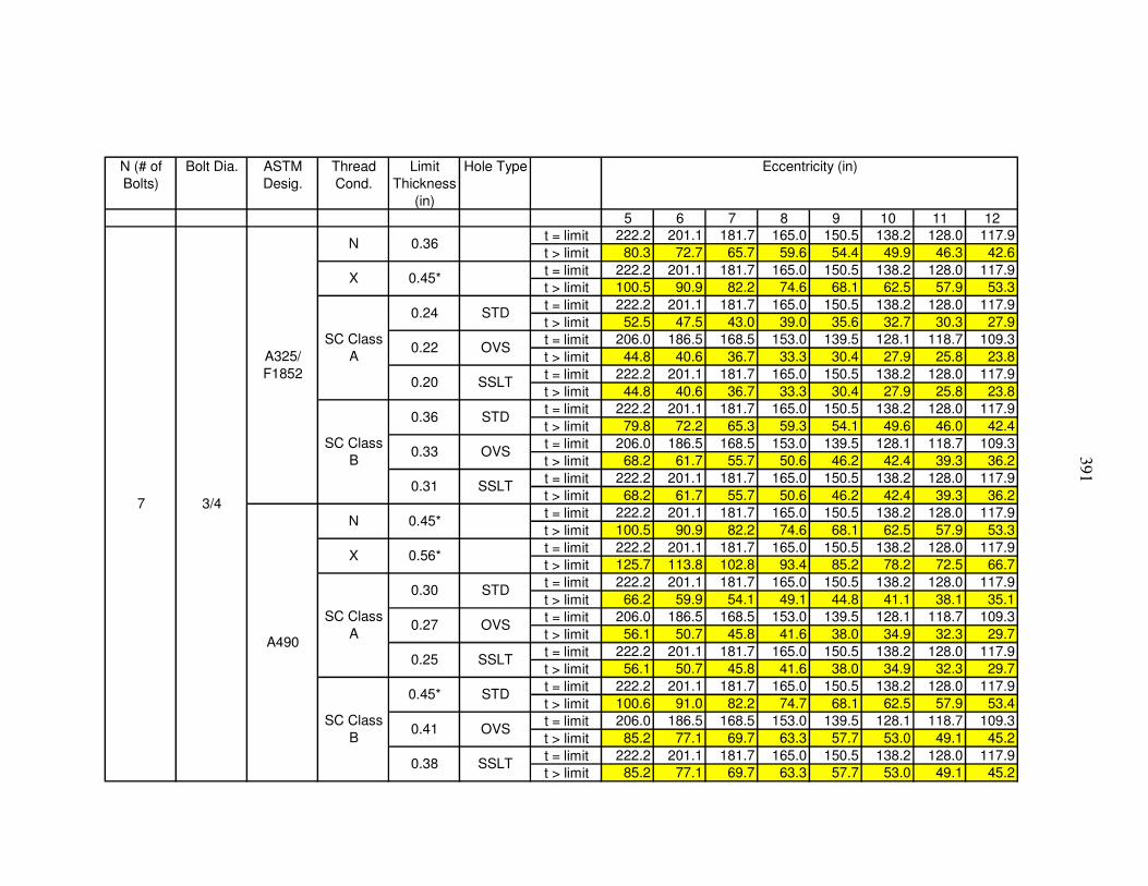
391
N (# of Bolts)
Bolt Dia. ASTM Desig.
Thread Cond.
Limit Thickness
(in)
Hole Type
5 6 7 8 9 10 11 12t = limit 222.2 201.1 181.7 165.0 150.5 138.2 128.0 117.9t > limit 80.3 72.7 65.7 59.6 54.4 49.9 46.3 42.6t = limit 222.2 201.1 181.7 165.0 150.5 138.2 128.0 117.9t > limit 100.5 90.9 82.2 74.6 68.1 62.5 57.9 53.3t = limit 222.2 201.1 181.7 165.0 150.5 138.2 128.0 117.9t > limit 52.5 47.5 43.0 39.0 35.6 32.7 30.3 27.9t = limit 206.0 186.5 168.5 153.0 139.5 128.1 118.7 109.3t > limit 44.8 40.6 36.7 33.3 30.4 27.9 25.8 23.8t = limit 222.2 201.1 181.7 165.0 150.5 138.2 128.0 117.9t > limit 44.8 40.6 36.7 33.3 30.4 27.9 25.8 23.8t = limit 222.2 201.1 181.7 165.0 150.5 138.2 128.0 117.9t > limit 79.8 72.2 65.3 59.3 54.1 49.6 46.0 42.4t = limit 206.0 186.5 168.5 153.0 139.5 128.1 118.7 109.3t > limit 68.2 61.7 55.7 50.6 46.2 42.4 39.3 36.2t = limit 222.2 201.1 181.7 165.0 150.5 138.2 128.0 117.9t > limit 68.2 61.7 55.7 50.6 46.2 42.4 39.3 36.2t = limit 222.2 201.1 181.7 165.0 150.5 138.2 128.0 117.9t > limit 100.5 90.9 82.2 74.6 68.1 62.5 57.9 53.3t = limit 222.2 201.1 181.7 165.0 150.5 138.2 128.0 117.9t > limit 125.7 113.8 102.8 93.4 85.2 78.2 72.5 66.7t = limit 222.2 201.1 181.7 165.0 150.5 138.2 128.0 117.9t > limit 66.2 59.9 54.1 49.1 44.8 41.1 38.1 35.1t = limit 206.0 186.5 168.5 153.0 139.5 128.1 118.7 109.3t > limit 56.1 50.7 45.8 41.6 38.0 34.9 32.3 29.7t = limit 222.2 201.1 181.7 165.0 150.5 138.2 128.0 117.9t > limit 56.1 50.7 45.8 41.6 38.0 34.9 32.3 29.7t = limit 222.2 201.1 181.7 165.0 150.5 138.2 128.0 117.9t > limit 100.6 91.0 82.2 74.7 68.1 62.5 57.9 53.4t = limit 206.0 186.5 168.5 153.0 139.5 128.1 118.7 109.3t > limit 85.2 77.1 69.7 63.3 57.7 53.0 49.1 45.2t = limit 222.2 201.1 181.7 165.0 150.5 138.2 128.0 117.9t > limit 85.2 77.1 69.7 63.3 57.7 53.0 49.1 45.2
SC Class B
0.45* STD
0.41 OVS
0.38 SSLT
0.27 OVS
0.25 SSLTA490
N 0.45*
X 0.56*
SC Class A
0.30 STD
SC Class B
0.36 STD
0.33 OVS
0.31 SSLT
SC Class A
0.24 STD
0.22 OVS
0.20 SSLT
Eccentricity (in)
7 3/4
A325/ F1852
N 0.36
X 0.45*

392
N (# of Bolts)
Bolt Dia. ASTM Desig.
Thread Cond.
Limit Thickness
(in)
Hole Type
5 6 7 8 9 10 11 12t = limit 269.7 247.7 226.6 207.7 191.0 176.0 163.7 151.4t > limit 97.5 89.5 81.9 75.0 69.0 63.6 59.1 54.7t = limit 269.7 247.7 226.6 207.7 191.0 176.0 163.7 151.4t > limit 122.0 112.0 102.5 93.9 86.4 79.6 74.0 68.5t = limit 269.7 247.7 226.6 207.7 191.0 176.0 163.7 151.4t > limit 63.8 58.6 53.6 49.1 45.1 41.6 38.7 35.8t = limit 250.1 229.7 210.1 192.6 177.1 163.2 151.8 140.4t > limit 54.4 50.0 45.7 41.9 38.5 35.5 33.0 30.5t = limit 269.7 247.7 226.6 207.7 191.0 176.0 163.7 151.4t > limit 54.4 50.0 45.7 41.9 38.5 35.5 33.0 30.5t = limit 269.7 247.7 226.6 207.7 191.0 176.0 163.7 151.4t > limit 96.9 89.0 81.4 74.6 68.6 63.2 58.8 54.4t = limit 250.1 229.7 210.1 192.6 177.1 163.2 151.8 140.4t > limit 82.7 76.0 69.5 63.7 58.6 54.0 50.2 46.4t = limit 269.7 247.7 226.6 207.7 191.0 176.0 163.7 151.4t > limit 82.7 76.0 69.5 63.7 58.6 54.0 50.2 46.4t = limit 269.7 247.7 226.6 207.7 191.0 176.0 163.7 151.4t > limit 122.0 112.0 102.5 93.9 86.4 79.6 74.0 68.5t = limit 269.7 247.7 226.6 207.7 191.0 176.0 163.7 151.4t > limit 152.6 140.2 128.2 117.5 108.1 99.6 92.6 85.7t = limit 269.7 247.7 226.6 207.7 191.0 176.0 163.7 151.4t > limit 80.3 73.8 67.5 61.8 56.9 52.4 48.7 45.1t = limit 250.1 229.7 210.1 192.6 177.1 163.2 151.8 140.4t > limit 68.0 62.5 57.2 52.4 48.2 44.4 41.3 38.2t = limit 269.7 247.7 226.6 207.7 191.0 176.0 163.7 151.4t > limit 68.0 62.5 57.2 52.4 48.2 44.4 41.3 38.2t = limit 269.7 247.7 226.6 207.7 191.0 176.0 163.7 151.4t > limit 122.1 112.1 102.5 94.0 86.4 79.6 74.1 68.5t = limit 250.1 229.7 210.1 192.6 177.1 163.2 151.8 140.4t > limit 103.4 95.0 86.9 79.6 73.2 67.5 62.8 58.0t = limit 269.7 247.7 226.6 207.7 191.0 176.0 163.7 151.4t > limit 103.4 95.0 86.9 79.6 73.2 67.5 62.8 58.0
SC Class B
0.45* STD
0.41 OVS
0.38 SSLT
0.27 OVS
0.25 SSLTA490
N 0.45*
X 0.56*
SC Class A
0.30 STD
SC Class B
0.36 STD
0.33 OVS
0.31 SSLT
SC Class A
0.24 STD
0.22 OVS
0.20 SSLT
Eccentricity (in)
8 3/4
A325/ F1852
N 0.36
X 0.45*

393
N (# of Bolts)
Bolt Dia. ASTM Desig.
Thread Cond.
Limit Thickness
(in)
Hole Type
5 6 7 8 9 10 11 12t = limit 317.7 294.8 272.8 252.1 233.6 216.5 202.2 187.9t > limit 114.8 106.5 98.6 91.1 84.4 78.2 73.1 67.9t = limit 317.7 294.8 272.8 252.1 233.6 216.5 202.2 187.9t > limit 143.7 133.3 123.4 114.0 105.7 97.9 91.4 85.0t = limit 317.7 294.8 272.8 252.1 233.6 216.5 202.2 187.9t > limit 75.1 69.7 64.5 59.6 55.2 51.2 47.8 44.4t = limit 294.6 273.4 253.0 233.8 216.6 200.7 187.5 174.2t > limit 64.1 59.5 55.1 50.9 47.2 43.7 40.8 37.9t = limit 317.7 294.8 272.8 252.1 233.6 216.5 202.2 187.9t > limit 64.1 59.5 55.1 50.9 47.2 43.7 40.8 37.9t = limit 317.7 294.8 272.8 252.1 233.6 216.5 202.2 187.9t > limit 114.1 105.9 98.0 90.6 83.9 77.8 72.6 67.5t = limit 294.6 273.4 253.0 233.8 216.6 200.7 187.5 174.2t > limit 97.5 90.4 83.7 77.3 71.7 66.4 62.0 57.6t = limit 317.7 294.8 272.8 252.1 233.6 216.5 202.2 187.9t > limit 97.5 90.4 83.7 77.3 71.7 66.4 62.0 57.6t = limit 317.7 294.8 272.8 252.1 233.6 216.5 202.2 187.9t > limit 143.7 133.3 123.4 114.0 105.7 97.9 91.4 85.0t = limit 317.7 294.8 272.8 252.1 233.6 216.5 202.2 187.9t > limit 179.8 166.8 154.4 142.7 132.2 122.5 114.4 106.3t = limit 317.7 294.8 272.8 252.1 233.6 216.5 202.2 187.9t > limit 94.6 87.8 81.2 75.1 69.6 64.5 60.2 55.9t = limit 294.6 273.4 253.0 233.8 216.6 200.7 187.5 174.2t > limit 80.1 74.4 68.8 63.6 58.9 54.6 51.0 47.4t = limit 317.7 294.8 272.8 252.1 233.6 216.5 202.2 187.9t > limit 80.1 74.4 68.8 63.6 58.9 54.6 51.0 47.4t = limit 317.7 294.8 272.8 252.1 233.6 216.5 202.2 187.9t > limit 143.8 133.4 123.5 114.1 105.7 98.0 91.5 85.0t = limit 294.6 273.4 253.0 233.8 216.6 200.7 187.5 174.2t > limit 121.8 113.0 104.6 96.7 89.6 83.0 77.5 72.0t = limit 317.7 294.8 272.8 252.1 233.6 216.5 202.2 187.9t > limit 121.8 113.0 104.6 96.7 89.6 83.0 77.5 72.0
SC Class B
0.45* STD
0.41 OVS
0.38 SSLT
0.27 OVS
0.25 SSLTA490
N 0.45*
X 0.56*
SC Class A
0.30 STD
SC Class B
0.36 STD
0.33 OVS
0.31 SSLT
SC Class A
0.24 STD
0.22 OVS
0.20 SSLT
Eccentricity (in)
9 3/4
A325/ F1852
N 0.36
X 0.45*

394
N (# of Bolts)
Bolt Dia. ASTM Desig.
Thread Cond.
Limit Thickness
(in)
Hole Type
5 6 7 8 9 10 11 12t = limit 365.2 342.8 320.3 298.3 278.1 259.2 242.9 226.6t > limit 132.0 123.9 115.8 107.8 100.5 93.7 87.8 81.9t = limit 365.2 342.8 320.3 298.3 278.1 259.2 242.9 226.6t > limit 165.2 155.0 144.9 134.9 125.8 117.2 109.8 102.5t = limit 365.2 342.8 320.3 298.3 278.1 259.2 242.9 226.6t > limit 86.3 81.0 75.7 70.5 65.7 61.3 57.4 53.6t = limit 338.6 317.8 297.0 276.6 257.9 240.3 225.2 210.1t > limit 73.7 69.2 64.6 60.2 56.1 52.3 49.0 45.7t = limit 365.2 342.8 320.3 298.3 278.1 259.2 242.9 226.6t > limit 73.7 69.2 64.6 60.2 56.1 52.3 49.0 45.7t = limit 365.2 342.8 320.3 298.3 278.1 259.2 242.9 226.6t > limit 131.2 123.1 115.1 107.2 99.9 93.1 87.3 81.4t = limit 338.6 317.8 297.0 276.6 257.9 240.3 225.2 210.1t > limit 112.0 105.1 98.3 91.5 85.3 79.5 74.5 69.5t = limit 365.2 342.8 320.3 298.3 278.1 259.2 242.9 226.6t > limit 112.0 105.1 98.3 91.5 85.3 79.5 74.5 69.5t = limit 365.2 342.8 320.3 298.3 278.1 259.2 242.9 226.6t > limit 165.2 155.0 144.9 134.9 125.8 117.2 109.8 102.5t = limit 365.2 342.8 320.3 298.3 278.1 259.2 242.9 226.6t > limit 206.7 194.0 181.3 168.8 157.4 146.7 137.4 128.2t = limit 365.2 342.8 320.3 298.3 278.1 259.2 242.9 226.6t > limit 108.7 102.0 95.4 88.8 82.8 77.2 72.3 67.5t = limit 338.6 317.8 297.0 276.6 257.9 240.3 225.2 210.1t > limit 92.1 86.5 80.8 75.3 70.2 65.4 61.3 57.2t = limit 365.2 342.8 320.3 298.3 278.1 259.2 242.9 226.6t > limit 92.1 86.5 80.8 75.3 70.2 65.4 61.3 57.2t = limit 365.2 342.8 320.3 298.3 278.1 259.2 242.9 226.6t > limit 165.3 155.1 145.0 135.0 125.8 117.3 109.9 102.5t = limit 338.6 317.8 297.0 276.6 257.9 240.3 225.2 210.1t > limit 140.0 131.4 122.8 114.4 106.6 99.4 93.1 86.9t = limit 365.2 342.8 320.3 298.3 278.1 259.2 242.9 226.6t > limit 140.0 131.4 122.8 114.4 106.6 99.4 93.1 86.9
SC Class B
0.45* STD
0.41 OVS
0.38 SSLT
0.27 OVS
0.25 SSLTA490
N 0.45*
X 0.56*
SC Class A
0.30 STD
SC Class B
0.36 STD
0.33 OVS
0.31 SSLT
SC Class A
0.24 STD
0.22 OVS
0.20 SSLT
Eccentricity (in)
10 3/4
A325/ F1852
N 0.36
X 0.45*

395
N (# of Bolts)
Bolt Dia. ASTM Desig.
Thread Cond.
Limit Thickness
(in)
Hole Type
5 6 7 8 9 10 11 12t = limit 412.7 390.3 367.8 345.4 323.8 303.6 285.8 268.0t > limit 149.1 141.0 132.9 124.8 117.0 109.7 103.3 96.8t = limit 412.7 390.3 367.8 345.4 323.8 303.6 285.8 268.0t > limit 186.7 176.5 166.4 156.2 146.5 137.3 129.3 121.2t = limit 412.7 390.3 367.8 345.4 323.8 303.6 285.8 268.0t > limit 97.6 92.2 86.9 81.6 76.5 71.8 67.5 63.3t = limit 382.7 361.9 341.1 320.3 300.3 281.5 265.0 248.5t > limit 83.3 78.8 74.2 69.7 65.4 61.3 57.7 54.1t = limit 412.7 390.3 367.8 345.4 323.8 303.6 285.8 268.0t > limit 83.3 78.8 74.2 69.7 65.4 61.3 57.7 54.1t = limit 412.7 390.3 367.8 345.4 323.8 303.6 285.8 268.0t > limit 148.3 140.2 132.2 124.1 116.3 109.1 102.7 96.3t = limit 382.7 361.9 341.1 320.3 300.3 281.5 265.0 248.5t > limit 126.6 119.7 112.8 106.0 99.3 93.1 87.7 82.2t = limit 412.7 390.3 367.8 345.4 323.8 303.6 285.8 268.0t > limit 126.6 119.7 112.8 106.0 99.3 93.1 87.7 82.2t = limit 412.7 390.3 367.8 345.4 323.8 303.6 285.8 268.0t > limit 186.7 176.5 166.4 156.2 146.5 137.3 129.3 121.2t = limit 412.7 390.3 367.8 345.4 323.8 303.6 285.8 268.0t > limit 233.6 220.9 208.2 195.5 183.3 171.8 161.7 151.6t = limit 412.7 390.3 367.8 345.4 323.8 303.6 285.8 268.0t > limit 122.9 116.2 109.5 102.8 96.4 90.4 85.1 79.8t = limit 382.7 361.9 341.1 320.3 300.3 281.5 265.0 248.5t > limit 104.1 98.5 92.8 87.1 81.7 76.6 72.1 67.6t = limit 412.7 390.3 367.8 345.4 323.8 303.6 285.8 268.0t > limit 104.1 98.5 92.8 87.1 81.7 76.6 72.1 67.6t = limit 412.7 390.3 367.8 345.4 323.8 303.6 285.8 268.0t > limit 186.8 176.6 166.5 156.3 146.6 137.4 129.3 121.3t = limit 382.7 361.9 341.1 320.3 300.3 281.5 265.0 248.5t > limit 158.3 149.7 141.0 132.4 124.2 116.4 109.6 102.8t = limit 412.7 390.3 367.8 345.4 323.8 303.6 285.8 268.0t > limit 158.3 149.7 141.0 132.4 124.2 116.4 109.6 102.8
SC Class B
0.45* STD
0.41 OVS
0.38 SSLT
0.27 OVS
0.25 SSLTA490
N 0.45*
X 0.56*
SC Class A
0.30 STD
SC Class B
0.36 STD
0.33 OVS
0.31 SSLT
SC Class A
0.24 STD
0.22 OVS
0.20 SSLT
Eccentricity (in)
11 3/4
A325/ F1852
N 0.36
X 0.45*

396
N (# of Bolts)
Bolt Dia. ASTM Desig.
Thread Cond.
Limit Thickness
(in)
Hole Type
5 6 7 8 9 10 11 12t = limit 457.6 438.2 415.4 392.9 370.5 349.4 330.0 310.6t > limit 165.4 158.4 150.1 142.0 133.9 126.2 119.3 112.3t = limit 457.6 438.2 415.4 392.9 370.5 349.4 330.0 310.6t > limit 207.0 198.2 187.9 177.7 167.6 158.0 149.3 140.5t = limit 457.6 438.2 415.4 392.9 370.5 349.4 330.0 310.6t > limit 108.2 103.6 98.2 92.9 87.6 82.6 78.0 73.4t = limit 457.6 438.2 415.4 392.9 370.5 349.4 330.0 310.6t > limit 92.4 88.4 83.8 79.3 74.8 70.5 66.6 62.7t = limit 457.6 438.2 415.4 392.9 370.5 349.4 330.0 310.6t > limit 92.4 88.4 83.8 79.3 74.8 70.5 66.6 62.7t = limit 457.6 438.2 415.4 392.9 370.5 349.4 330.0 310.6t > limit 164.4 157.4 149.2 141.2 133.1 125.5 118.6 111.6t = limit 457.6 438.2 415.4 392.9 370.5 349.4 330.0 310.6t > limit 140.4 134.4 127.4 120.5 113.6 107.2 101.2 95.3t = limit 457.6 438.2 415.4 392.9 370.5 349.4 330.0 310.6t > limit 140.4 134.4 127.4 120.5 113.6 107.2 101.2 95.3t = limit 457.6 438.2 415.4 392.9 370.5 349.4 330.0 310.6t > limit 207.0 198.2 187.9 177.7 167.6 158.0 149.3 140.5t = limit 457.6 438.2 415.4 392.9 370.5 349.4 330.0 310.6t > limit 259.0 248.0 235.1 222.4 209.7 197.7 186.8 175.8t = limit 457.6 438.2 415.4 392.9 370.5 349.4 330.0 310.6t > limit 136.2 130.5 123.7 117.0 110.3 104.0 98.3 92.5t = limit 457.6 438.2 415.4 392.9 370.5 349.4 330.0 310.6t > limit 115.4 110.6 104.8 99.1 93.5 88.1 83.3 78.4t = limit 457.6 438.2 415.4 392.9 370.5 349.4 330.0 310.6t > limit 115.4 110.6 104.8 99.1 93.5 88.1 83.3 78.4t = limit 457.6 438.2 415.4 392.9 370.5 349.4 330.0 310.6t > limit 207.1 198.3 188.0 177.8 167.7 158.1 149.3 140.6t = limit 457.6 438.2 415.4 392.9 370.5 349.4 330.0 310.6t > limit 175.5 168.0 159.3 150.7 142.1 134.0 126.5 119.1t = limit 457.6 438.2 415.4 392.9 370.5 349.4 330.0 310.6t > limit 175.5 168.0 159.3 150.7 142.1 134.0 126.5 119.1
SC Class B
0.45* STD
0.41 OVS
0.38 SSLT
0.27 OVS
0.25 SSLTA490
N 0.45*
X 0.56*
SC Class A
0.30 STD
SC Class B
0.36 STD
0.33 OVS
0.31 SSLT
SC Class A
0.24 STD
0.22 OVS
0.20 SSLT
Eccentricity (in)
12 3/4
A325/ F1852
N 0.36
X 0.45*

397
APPENDIX N 7/8-INCH DIAMETER ALL-BOLTED A992 STEEL TEE CONNECTIONS
The tables given in Appendix N are all-bolted tee connections. The tees are A992
tees using either A325/F1852 or A490 7/8-inch diameter bolts. The edge distance, Leh, is
assumed to be 1.25 inches. Tees with a stem thickness less than the limiting thickness
use the first row for the appropriate connection type. The value given in the first row is
in units of kips per inch of stem thickness. The design capacity is the stem thickness
times the value given. Tees with a stem thickness greater than the limiting thickness use
the second row for the appropriate connection type. The value given in the second row is
in units of kips. The design capacity is the value given.
* Does not meet the ductility requirements of Part 9 in the AISC Manual.

398
N (# of Bolts)
Bolt Dia. ASTM Desig.
Thread Cond.
Limit Thickness
(in)
Hole Type
5 6 7 8 9 10 11 12t = limit 22.8 19.6 16.7 14.7 13.1 11.8 10.8 9.8t > limit 12.1 10.4 8.9 7.8 6.9 6.3 5.7 5.2t = limit 22.8 19.6 16.7 14.7 13.1 11.8 10.8 9.8t > limit 15.2 13.0 11.1 9.8 8.7 7.9 7.2 6.5t = limit 22.8 19.6 16.7 14.7 13.1 11.8 10.8 9.8t > limit 8.1 7.0 5.9 5.2 4.6 4.2 3.8 3.5t = limit 21.0 18.0 15.4 13.5 12.0 10.9 9.9 9.0t > limit 6.9 6.0 5.1 4.5 4.0 3.6 3.3 3.0t = limit 22.8 19.6 16.7 14.7 13.1 11.8 10.8 9.8t > limit 6.9 6.0 5.1 4.5 4.0 3.6 3.3 3.0t = limit 22.8 19.6 16.7 14.7 13.1 11.8 10.8 9.8t > limit 8.9 7.6 6.5 5.7 5.1 4.6 4.2 3.8t = limit 21.0 18.0 15.4 13.5 12.0 10.9 9.9 9.0t > limit 7.6 6.5 5.5 4.9 4.3 3.9 3.6 3.2t = limit 22.8 19.6 16.7 14.7 13.1 11.8 10.8 9.8t > limit 7.6 6.5 5.5 4.9 4.3 3.9 3.6 3.2t = limit 22.8 19.6 16.7 14.7 13.1 11.8 10.8 9.8t > limit 15.2 13.0 11.1 9.8 8.7 7.9 7.2 6.5t = limit 22.8 19.6 16.7 14.7 13.1 11.8 10.8 9.8t > limit 18.9 16.2 13.9 12.2 10.8 9.8 9.0 8.1t = limit 22.8 19.6 16.7 14.7 13.1 11.8 10.8 9.8t > limit 10.2 8.8 7.5 6.6 5.9 5.3 4.8 4.4t = limit 21.0 18.0 15.4 13.5 12.0 10.9 9.9 9.0t > limit 8.7 7.4 6.4 5.6 5.0 4.5 4.1 3.7t = limit 22.8 19.6 16.7 14.7 13.1 11.8 10.8 9.8t > limit 8.7 7.4 6.4 5.6 5.0 4.5 4.1 3.7t = limit 22.8 19.6 16.7 14.7 13.1 11.8 10.8 9.8t > limit 15.6 13.4 11.4 10.0 8.9 8.1 7.4 6.7t = limit 21.0 18.0 15.4 13.5 12.0 10.9 9.9 9.0t > limit 13.2 11.3 9.7 8.5 7.5 6.8 6.2 5.7t = limit 22.8 19.6 16.7 14.7 13.1 11.8 10.8 9.8t > limit 13.2 11.3 9.7 8.5 7.5 6.8 6.2 5.7
Eccentricity (in)
2 7/8
A325/ F1852
N 0.49
X 0.66*
SC Class A
0.36 STD
0.33 OVS
0.30 SSLT
SC Class B
0.54* STD
0.50* OVS
0.46 SSLT
A490
N 0.66*
X 0.83*
SC Class A
0.45 STD
0.41 OVS
0.38 SSLT
SC Class B
0.68* STD
0.63* OVS
0.58* SSLT

399
N (# of Bolts)
Bolt Dia. ASTM Desig.
Thread Cond.
Limit Thickness
(in)
Hole Type
5 6 7 8 9 10 11 12t = limit 46.9 39.6 33.9 29.8 26.5 24.1 22.0 20.0t > limit 24.8 21.0 17.9 15.8 14.0 12.7 11.7 10.6t = limit 46.9 39.6 33.9 29.8 26.5 24.1 22.0 20.0t > limit 31.2 26.3 22.5 19.8 17.6 16.0 14.6 13.3t = limit 46.9 39.6 33.9 29.8 26.5 24.1 22.0 20.0t > limit 16.7 14.1 12.0 10.6 9.4 8.6 7.8 7.1t = limit 43.1 36.4 31.1 27.4 24.4 22.1 20.3 18.4t > limit 14.3 12.0 10.3 9.1 8.1 7.3 6.7 6.1t = limit 46.9 39.6 33.9 29.8 26.5 24.1 22.0 20.0t > limit 14.3 12.0 10.3 9.1 8.1 7.3 6.7 6.1t = limit 46.9 39.6 33.9 29.8 26.5 24.1 22.0 20.0t > limit 18.2 15.3 13.1 11.5 10.3 9.3 8.5 7.7t = limit 43.1 36.4 31.1 27.4 24.4 22.1 20.3 18.4t > limit 15.5 13.1 11.2 9.9 8.8 8.0 7.3 6.6t = limit 46.9 39.6 33.9 29.8 26.5 24.1 22.0 20.0t > limit 15.5 13.1 11.2 9.9 8.8 8.0 7.3 6.6t = limit 46.9 39.6 33.9 29.8 26.5 24.1 22.0 20.0t > limit 31.2 26.3 22.5 19.8 17.6 16.0 14.6 13.3t = limit 46.9 39.6 33.9 29.8 26.5 24.1 22.0 20.0t > limit 38.9 32.8 28.1 24.7 22.0 19.9 18.3 16.6t = limit 46.9 39.6 33.9 29.8 26.5 24.1 22.0 20.0t > limit 21.0 17.8 15.2 13.4 11.9 10.8 9.9 9.0t = limit 43.1 36.4 31.1 27.4 24.4 22.1 20.3 18.4t > limit 17.8 15.0 12.9 11.3 10.1 9.1 8.4 7.6t = limit 46.9 39.6 33.9 29.8 26.5 24.1 22.0 20.0t > limit 17.8 15.0 12.9 11.3 10.1 9.1 8.4 7.6t = limit 46.9 39.6 33.9 29.8 26.5 24.1 22.0 20.0t > limit 32.0 27.0 23.1 20.3 18.1 16.4 15.0 13.6t = limit 43.1 36.4 31.1 27.4 24.4 22.1 20.3 18.4t > limit 27.1 22.9 19.6 17.2 15.3 13.9 12.7 11.5t = limit 46.9 39.6 33.9 29.8 26.5 24.1 22.0 20.0t > limit 27.1 22.9 19.6 17.2 15.3 13.9 12.7 11.5
Eccentricity (in)
3 7/8
A325/ F1852
N 0.49
X 0.66*
SC Class A
0.36 STD
0.33 OVS
0.30 SSLT
SC Class B
0.54* STD
0.50* OVS
0.46 SSLT
A490
N 0.66*
X 0.83*
SC Class A
0.45 STD
0.41 OVS
0.38 SSLT
SC Class B
0.68* STD
0.63* OVS
0.58* SSLT
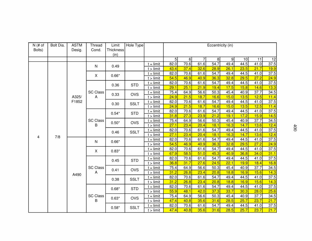
400
N (# of Bolts)
Bolt Dia. ASTM Desig.
Thread Cond.
Limit Thickness
(in)
Hole Type
5 6 7 8 9 10 11 12t = limit 82.0 70.6 61.6 54.7 49.4 44.5 41.0 37.5t > limit 43.4 37.4 32.6 28.9 26.1 23.5 21.7 19.9t = limit 82.0 70.6 61.6 54.7 49.4 44.5 41.0 37.5t > limit 54.5 46.9 40.9 36.3 32.8 29.5 27.2 24.9t = limit 82.0 70.6 61.6 54.7 49.4 44.5 41.0 37.5t > limit 29.1 25.1 21.9 19.4 17.5 15.8 14.6 13.3t = limit 75.4 64.9 56.6 50.3 45.4 40.9 37.7 34.5t > limit 24.9 21.5 18.7 16.6 15.0 13.5 12.5 11.4t = limit 82.0 70.6 61.6 54.7 49.4 44.5 41.0 37.5t > limit 24.9 21.5 18.7 16.6 15.0 13.5 12.5 11.4t = limit 82.0 70.6 61.6 54.7 49.4 44.5 41.0 37.5t > limit 31.8 27.3 23.9 21.2 19.1 17.2 15.9 14.5t = limit 75.4 64.9 56.6 50.3 45.4 40.9 37.7 34.5t > limit 27.1 23.4 20.4 18.1 16.3 14.7 13.6 12.4t = limit 82.0 70.6 61.6 54.7 49.4 44.5 41.0 37.5t > limit 27.1 23.4 20.4 18.1 16.3 14.7 13.6 12.4t = limit 82.0 70.6 61.6 54.7 49.4 44.5 41.0 37.5t > limit 54.5 46.9 40.9 36.3 32.8 29.5 27.2 24.9t = limit 82.0 70.6 61.6 54.7 49.4 44.5 41.0 37.5t > limit 67.9 58.5 51.0 45.3 40.9 36.8 34.0 31.1t = limit 82.0 70.6 61.6 54.7 49.4 44.5 41.0 37.5t > limit 36.8 31.7 27.6 24.5 22.1 19.9 18.4 16.8t = limit 75.4 64.9 56.6 50.3 45.4 40.9 37.7 34.5t > limit 31.2 26.8 23.4 20.8 18.8 16.9 15.6 14.3t = limit 82.0 70.6 61.6 54.7 49.4 44.5 41.0 37.5t > limit 31.2 26.8 23.4 20.8 18.8 16.9 15.6 14.3t = limit 82.0 70.6 61.6 54.7 49.4 44.5 41.0 37.5t > limit 55.9 48.1 42.0 37.3 33.7 30.3 28.0 25.6t = limit 75.4 64.9 56.6 50.3 45.4 40.9 37.7 34.5t > limit 47.4 40.8 35.6 31.6 28.5 25.7 23.7 21.7t = limit 82.0 70.6 61.6 54.7 49.4 44.5 41.0 37.5t > limit 47.4 40.8 35.6 31.6 28.5 25.7 23.7 21.7
Eccentricity (in)
4 7/8
A325/ F1852
N 0.49
X 0.66*
SC Class A
0.36 STD
0.33 OVS
0.30 SSLT
SC Class B
0.54* STD
0.50* OVS
0.46 SSLT
A490
N 0.66*
X 0.83*
SC Class A
0.45 STD
0.41 OVS
0.38 SSLT
SC Class B
0.68* STD
0.63* OVS
0.58* SSLT

401
N (# of Bolts)
Bolt Dia. ASTM Desig.
Thread Cond.
Limit Thickness
(in)
Hole Type
5 6 7 8 9 10 11 12t = limit 120.8 105.7 93.0 83.2 74.7 67.7 62.4 57.1t > limit 63.9 55.9 49.2 44.1 39.5 35.9 33.0 30.2t = limit 120.8 105.7 93.0 83.2 74.7 67.7 62.4 57.1t > limit 80.2 70.2 61.8 55.3 49.6 45.0 41.5 37.9t = limit 120.8 105.7 93.0 83.2 74.7 67.7 62.4 57.1t > limit 42.9 37.6 33.1 29.6 26.5 24.1 22.2 20.3t = limit 111.0 97.1 85.5 76.5 68.6 62.3 57.4 52.5t > limit 36.7 32.1 28.3 25.3 22.7 20.6 19.0 17.4t = limit 120.8 105.7 93.0 83.2 74.7 67.7 62.4 57.1t > limit 36.7 32.1 28.3 25.3 22.7 20.6 19.0 17.4t = limit 120.8 105.7 93.0 83.2 74.7 67.7 62.4 57.1t > limit 46.8 40.9 36.0 32.2 28.9 26.2 24.2 22.1t = limit 111.0 97.1 85.5 76.5 68.6 62.3 57.4 52.5t > limit 40.0 35.0 30.8 27.5 24.7 22.4 20.7 18.9t = limit 120.8 105.7 93.0 83.2 74.7 67.7 62.4 57.1t > limit 40.0 35.0 30.8 27.5 24.7 22.4 20.7 18.9t = limit 120.8 105.7 93.0 83.2 74.7 67.7 62.4 57.1t > limit 80.2 70.2 61.8 55.3 49.6 45.0 41.5 37.9t = limit 120.8 105.7 93.0 83.2 74.7 67.7 62.4 57.1t > limit 100.0 87.5 77.1 69.0 61.9 56.1 51.7 47.3t = limit 120.8 105.7 93.0 83.2 74.7 67.7 62.4 57.1t > limit 54.2 47.4 41.7 37.3 33.5 30.4 28.0 25.6t = limit 111.0 97.1 85.5 76.5 68.6 62.3 57.4 52.5t > limit 45.9 40.1 35.3 31.6 28.4 25.7 23.7 21.7t = limit 120.8 105.7 93.0 83.2 74.7 67.7 62.4 57.1t > limit 45.9 40.1 35.3 31.6 28.4 25.7 23.7 21.7t = limit 120.8 105.7 93.0 83.2 74.7 67.7 62.4 57.1t > limit 82.3 72.0 63.4 56.7 50.9 46.2 42.6 38.9t = limit 111.0 97.1 85.5 76.5 68.6 62.3 57.4 52.5t > limit 69.7 61.0 53.7 48.1 43.1 39.1 36.0 33.0t = limit 120.8 105.7 93.0 83.2 74.7 67.7 62.4 57.1t > limit 69.7 61.0 53.7 48.1 43.1 39.1 36.0 33.0
Eccentricity (in)
5 7/8
A325/ F1852
N 0.49
X 0.66*
SC Class A
0.36 STD
0.33 OVS
0.30 SSLT
SC Class B
0.54* STD
0.50* OVS
0.46 SSLT
A490
N 0.66*
X 0.83*
SC Class A
0.45 STD
0.41 OVS
0.38 SSLT
SC Class B
0.68* STD
0.63* OVS
0.58* SSLT

402
N (# of Bolts)
Bolt Dia. ASTM Desig.
Thread Cond.
Limit Thickness
(in)
Hole Type
5 6 7 8 9 10 11 12t = limit 162.4 144.8 129.3 116.3 105.7 96.3 88.9 81.6t > limit 86.0 76.7 68.5 61.6 55.9 51.0 47.1 43.2t = limit 162.4 144.8 129.3 116.3 105.7 96.3 88.9 81.6t > limit 107.9 96.2 85.9 77.2 70.2 64.0 59.1 54.2t = limit 162.4 144.8 129.3 116.3 105.7 96.3 88.9 81.6t > limit 57.7 51.5 46.0 41.3 37.6 34.2 31.6 29.0t = limit 149.3 133.1 118.9 106.9 97.1 88.5 81.8 75.0t > limit 49.4 44.0 39.3 35.3 32.1 29.3 27.0 24.8t = limit 162.4 144.8 129.3 116.3 105.7 96.3 88.9 81.6t > limit 49.4 44.0 39.3 35.3 32.1 29.3 27.0 24.8t = limit 162.4 144.8 129.3 116.3 105.7 96.3 88.9 81.6t > limit 62.9 56.1 50.1 45.1 40.9 37.3 34.5 31.6t = limit 149.3 133.1 118.9 106.9 97.1 88.5 81.8 75.0t > limit 53.7 47.9 42.8 38.5 35.0 31.9 29.4 27.0t = limit 162.4 144.8 129.3 116.3 105.7 96.3 88.9 81.6t > limit 53.7 47.9 42.8 38.5 35.0 31.9 29.4 27.0t = limit 162.4 144.8 129.3 116.3 105.7 96.3 88.9 81.6t > limit 107.9 96.2 85.9 77.2 70.2 64.0 59.1 54.2t = limit 162.4 144.8 129.3 116.3 105.7 96.3 88.9 81.6t > limit 134.5 120.0 107.1 96.3 87.5 79.8 73.7 67.6t = limit 162.4 144.8 129.3 116.3 105.7 96.3 88.9 81.6t > limit 72.8 65.0 58.0 52.2 47.4 43.2 39.9 36.6t = limit 149.3 133.1 118.9 106.9 97.1 88.5 81.8 75.0t > limit 61.7 55.0 49.1 44.2 40.1 36.6 33.8 31.0t = limit 162.4 144.8 129.3 116.3 105.7 96.3 88.9 81.6t > limit 61.7 55.0 49.1 44.2 40.1 36.6 33.8 31.0t = limit 162.4 144.8 129.3 116.3 105.7 96.3 88.9 81.6t > limit 110.7 98.7 88.2 79.3 72.0 65.6 60.6 55.6t = limit 149.3 133.1 118.9 106.9 97.1 88.5 81.8 75.0t > limit 93.8 83.6 74.7 67.1 61.0 55.6 51.4 47.1t = limit 162.4 144.8 129.3 116.3 105.7 96.3 88.9 81.6t > limit 93.8 83.6 74.7 67.1 61.0 55.6 51.4 47.1
Eccentricity (in)
6 7/8
A325/ F1852
N 0.49
X 0.66*
SC Class A
0.36 STD
0.33 OVS
0.30 SSLT
SC Class B
0.54* STD
0.50* OVS
0.46 SSLT
A490
N 0.66*
X 0.83*
SC Class A
0.45 STD
0.41 OVS
0.38 SSLT
SC Class B
0.68* STD
0.63* OVS
0.58* SSLT

403
N (# of Bolts)
Bolt Dia. ASTM Desig.
Thread Cond.
Limit Thickness
(in)
Hole Type
5 6 7 8 9 10 11 12t = limit 206.0 186.5 168.5 153.0 139.5 128.1 118.7 109.3t > limit 109.1 98.7 89.2 81.0 73.9 67.8 62.9 57.9t = limit 206.0 186.5 168.5 153.0 139.5 128.1 118.7 109.3t > limit 136.9 123.8 111.9 101.6 92.7 85.1 78.9 72.6t = limit 206.0 186.5 168.5 153.0 139.5 128.1 118.7 109.3t > limit 73.2 66.3 59.9 54.4 49.6 45.5 42.2 38.9t = limit 189.4 171.4 154.9 140.6 128.3 117.8 109.1 100.5t > limit 62.6 56.7 51.2 46.5 42.4 38.9 36.1 33.2t = limit 206.0 186.5 168.5 153.0 139.5 128.1 118.7 109.3t > limit 62.6 56.7 51.2 46.5 42.4 38.9 36.1 33.2t = limit 206.0 186.5 168.5 153.0 139.5 128.1 118.7 109.3t > limit 79.8 72.2 65.3 59.3 54.1 49.6 46.0 42.4t = limit 189.4 171.4 154.9 140.6 128.3 117.8 109.1 100.5t > limit 68.2 61.7 55.7 50.6 46.2 42.4 39.3 36.2t = limit 206.0 186.5 168.5 153.0 139.5 128.1 118.7 109.3t > limit 68.2 61.7 55.7 50.6 46.2 42.4 39.3 36.2t = limit 206.0 186.5 168.5 153.0 139.5 128.1 118.7 109.3t > limit 136.9 123.8 111.9 101.6 92.7 85.1 78.9 72.6t = limit 206.0 186.5 168.5 153.0 139.5 128.1 118.7 109.3t > limit 170.7 154.5 139.6 126.8 115.6 106.1 98.4 90.6t = limit 206.0 186.5 168.5 153.0 139.5 128.1 118.7 109.3t > limit 92.4 83.6 75.6 68.6 62.6 57.5 53.3 49.0t = limit 189.4 171.4 154.9 140.6 128.3 117.8 109.1 100.5t > limit 78.3 70.8 64.0 58.1 53.0 48.7 45.1 41.5t = limit 206.0 186.5 168.5 153.0 139.5 128.1 118.7 109.3t > limit 78.3 70.8 64.0 58.1 53.0 48.7 45.1 41.5t = limit 206.0 186.5 168.5 153.0 139.5 128.1 118.7 109.3t > limit 140.5 127.1 114.9 104.3 95.1 87.3 80.9 74.5t = limit 189.4 171.4 154.9 140.6 128.3 117.8 109.1 100.5t > limit 119.0 107.7 97.3 88.4 80.6 74.0 68.6 63.1t = limit 206.0 186.5 168.5 153.0 139.5 128.1 118.7 109.3t > limit 119.0 107.7 97.3 88.4 80.6 74.0 68.6 63.1
Eccentricity (in)
7 7/8
A325/ F1852
N 0.49
X 0.66*
SC Class A
0.36 STD
0.33 OVS
0.30 SSLT
SC Class B
0.54* STD
0.50* OVS
0.46 SSLT
A490
N 0.66*
X 0.83*
SC Class A
0.45 STD
0.41 OVS
0.38 SSLT
SC Class B
0.68* STD
0.63* OVS
0.58* SSLT

404
N (# of Bolts)
Bolt Dia. ASTM Desig.
Thread Cond.
Limit Thickness
(in)
Hole Type
5 6 7 8 9 10 11 12t = limit 250.1 229.7 210.1 192.6 177.1 163.2 151.8 140.4t > limit 132.4 121.6 111.2 102.0 93.7 86.4 80.4 74.3t = limit 250.1 229.7 210.1 192.6 177.1 163.2 151.8 140.4t > limit 166.1 152.6 139.6 127.9 117.6 108.4 100.8 93.2t = limit 250.1 229.7 210.1 192.6 177.1 163.2 151.8 140.4t > limit 88.9 81.6 74.7 68.4 62.9 58.0 53.9 49.9t = limit 229.9 211.1 193.1 177.0 162.8 150.0 139.5 129.0t > limit 76.0 69.8 63.9 58.5 53.8 49.6 46.1 42.7t = limit 250.1 229.7 210.1 192.6 177.1 163.2 151.8 140.4t > limit 76.0 69.8 63.9 58.5 53.8 49.6 46.1 42.7t = limit 250.1 229.7 210.1 192.6 177.1 163.2 151.8 140.4t > limit 96.9 89.0 81.4 74.6 68.6 63.2 58.8 54.4t = limit 229.9 211.1 193.1 177.0 162.8 150.0 139.5 129.0t > limit 82.7 76.0 69.5 63.7 58.6 54.0 50.2 46.4t = limit 250.1 229.7 210.1 192.6 177.1 163.2 151.8 140.4t > limit 82.7 76.0 69.5 63.7 58.6 54.0 50.2 46.4t = limit 250.1 229.7 210.1 192.6 177.1 163.2 151.8 140.4t > limit 166.1 152.6 139.6 127.9 117.6 108.4 100.8 93.2t = limit 250.1 229.7 210.1 192.6 177.1 163.2 151.8 140.4t > limit 207.2 190.3 174.1 159.5 146.7 135.2 125.7 116.3t = limit 250.1 229.7 210.1 192.6 177.1 163.2 151.8 140.4t > limit 112.2 103.0 94.2 86.4 79.4 73.2 68.1 63.0t = limit 229.9 211.1 193.1 177.0 162.8 150.0 139.5 129.0t > limit 95.0 87.3 79.8 73.2 67.3 62.0 57.7 53.3t = limit 250.1 229.7 210.1 192.6 177.1 163.2 151.8 140.4t > limit 95.0 87.3 79.8 73.2 67.3 62.0 57.7 53.3t = limit 250.1 229.7 210.1 192.6 177.1 163.2 151.8 140.4t > limit 170.5 156.6 143.3 131.3 120.7 111.3 103.5 95.7t = limit 229.9 211.1 193.1 177.0 162.8 150.0 139.5 129.0t > limit 144.4 132.6 121.3 111.2 102.3 94.2 87.6 81.0t = limit 250.1 229.7 210.1 192.6 177.1 163.2 151.8 140.4t > limit 144.4 132.6 121.3 111.2 102.3 94.2 87.6 81.0
Eccentricity (in)
8 7/8
A325/ F1852
N 0.49
X 0.66*
SC Class A
0.36 STD
0.33 OVS
0.30 SSLT
SC Class B
0.54* STD
0.50* OVS
0.46 SSLT
A490
N 0.66*
X 0.83*
SC Class A
0.45 STD
0.41 OVS
0.38 SSLT
SC Class B
0.68* STD
0.63* OVS
0.58* SSLT

405
N (# of Bolts)
Bolt Dia. ASTM Desig.
Thread Cond.
Limit Thickness
(in)
Hole Type
5 6 7 8 9 10 11 12t = limit 294.6 273.4 253.0 233.8 216.6 200.7 187.5 174.2t > limit 156.0 144.7 133.9 123.8 114.7 106.3 99.3 92.2t = limit 294.6 273.4 253.0 233.8 216.6 200.7 187.5 174.2t > limit 195.7 181.6 168.0 155.3 143.9 133.3 124.5 115.7t = limit 294.6 273.4 253.0 233.8 216.6 200.7 187.5 174.2t > limit 104.7 97.2 89.9 83.1 77.0 71.3 66.6 61.9t = limit 270.8 251.3 232.5 214.9 199.1 184.5 172.3 160.1t > limit 89.5 83.1 76.9 71.1 65.8 61.0 57.0 52.9t = limit 294.6 273.4 253.0 233.8 216.6 200.7 187.5 174.2t > limit 89.5 83.1 76.9 71.1 65.8 61.0 57.0 52.9t = limit 294.6 273.4 253.0 233.8 216.6 200.7 187.5 174.2t > limit 114.1 105.9 98.0 90.6 83.9 77.8 72.6 67.5t = limit 270.8 251.3 232.5 214.9 199.1 184.5 172.3 160.1t > limit 97.5 90.4 83.7 77.3 71.7 66.4 62.0 57.6t = limit 294.6 273.4 253.0 233.8 216.6 200.7 187.5 174.2t > limit 97.5 90.4 83.7 77.3 71.7 66.4 62.0 57.6t = limit 294.6 273.4 253.0 233.8 216.6 200.7 187.5 174.2t > limit 195.7 181.6 168.0 155.3 143.9 133.3 124.5 115.7t = limit 294.6 273.4 253.0 233.8 216.6 200.7 187.5 174.2t > limit 244.0 226.5 209.6 193.7 179.5 166.3 155.3 144.3t = limit 294.6 273.4 253.0 233.8 216.6 200.7 187.5 174.2t > limit 132.1 122.6 113.5 104.9 97.2 90.0 84.1 78.1t = limit 270.8 251.3 232.5 214.9 199.1 184.5 172.3 160.1t > limit 111.9 103.9 96.1 88.8 82.3 76.3 71.2 66.2t = limit 294.6 273.4 253.0 233.8 216.6 200.7 187.5 174.2t > limit 111.9 103.9 96.1 88.8 82.3 76.3 71.2 66.2t = limit 294.6 273.4 253.0 233.8 216.6 200.7 187.5 174.2t > limit 200.8 186.4 172.5 159.4 147.7 136.9 127.8 118.8t = limit 270.8 251.3 232.5 214.9 199.1 184.5 172.3 160.1t > limit 170.1 157.9 146.1 135.0 125.1 115.9 108.3 100.6t = limit 294.6 273.4 253.0 233.8 216.6 200.7 187.5 174.2t > limit 170.1 157.9 146.1 135.0 125.1 115.9 108.3 100.6
Eccentricity (in)
9 7/8
A325/ F1852
N 0.49
X 0.66*
SC Class A
0.36 STD
0.33 OVS
0.30 SSLT
SC Class B
0.54* STD
0.50* OVS
0.46 SSLT
A490
N 0.66*
X 0.83*
SC Class A
0.45 STD
0.41 OVS
0.38 SSLT
SC Class B
0.68* STD
0.63* OVS
0.58* SSLT

406
N (# of Bolts)
Bolt Dia. ASTM Desig.
Thread Cond.
Limit Thickness
(in)
Hole Type
5 6 7 8 9 10 11 12t = limit 338.6 317.8 297.0 276.6 257.9 240.3 225.2 210.1t > limit 179.3 168.3 157.2 146.4 136.5 127.2 119.2 111.2t = limit 338.6 317.8 297.0 276.6 257.9 240.3 225.2 210.1t > limit 224.9 211.1 197.3 183.7 171.3 159.6 149.6 139.6t = limit 338.6 317.8 297.0 276.6 257.9 240.3 225.2 210.1t > limit 120.4 113.0 105.6 98.3 91.6 85.4 80.0 74.7t = limit 311.3 292.1 273.0 254.3 237.0 220.9 207.0 193.1t > limit 102.9 96.6 90.3 84.1 78.4 73.0 68.4 63.9t = limit 338.6 317.8 297.0 276.6 257.9 240.3 225.2 210.1t > limit 102.9 96.6 90.3 84.1 78.4 73.0 68.4 63.9t = limit 338.6 317.8 297.0 276.6 257.9 240.3 225.2 210.1t > limit 131.2 123.1 115.1 107.2 99.9 93.1 87.3 81.4t = limit 311.3 292.1 273.0 254.3 237.0 220.9 207.0 193.1t > limit 112.0 105.1 98.3 91.5 85.3 79.5 74.5 69.5t = limit 338.6 317.8 297.0 276.6 257.9 240.3 225.2 210.1t > limit 112.0 105.1 98.3 91.5 85.3 79.5 74.5 69.5t = limit 338.6 317.8 297.0 276.6 257.9 240.3 225.2 210.1t > limit 224.9 211.1 197.3 183.7 171.3 159.6 149.6 139.6t = limit 338.6 317.8 297.0 276.6 257.9 240.3 225.2 210.1t > limit 280.5 263.3 246.1 229.2 213.6 199.1 186.6 174.1t = limit 338.6 317.8 297.0 276.6 257.9 240.3 225.2 210.1t > limit 151.9 142.6 133.2 124.1 115.7 107.8 101.0 94.2t = limit 311.3 292.1 273.0 254.3 237.0 220.9 207.0 193.1t > limit 128.7 120.7 112.8 105.1 98.0 91.3 85.6 79.8t = limit 338.6 317.8 297.0 276.6 257.9 240.3 225.2 210.1t > limit 128.7 120.7 112.8 105.1 98.0 91.3 85.6 79.8t = limit 338.6 317.8 297.0 276.6 257.9 240.3 225.2 210.1t > limit 230.9 216.7 202.5 188.6 175.8 163.8 153.5 143.3t = limit 311.3 292.1 273.0 254.3 237.0 220.9 207.0 193.1t > limit 195.5 183.5 171.5 159.7 148.9 138.8 130.1 121.3t = limit 338.6 317.8 297.0 276.6 257.9 240.3 225.2 210.1t > limit 195.5 183.5 171.5 159.7 148.9 138.8 130.1 121.3
Eccentricity (in)
10 7/8
A325/ F1852
N 0.49
X 0.66*
SC Class A
0.36 STD
0.33 OVS
0.30 SSLT
SC Class B
0.54* STD
0.50* OVS
0.46 SSLT
A490
N 0.66*
X 0.83*
SC Class A
0.45 STD
0.41 OVS
0.38 SSLT
SC Class B
0.68* STD
0.63* OVS
0.58* SSLT

407
N (# of Bolts)
Bolt Dia. ASTM Desig.
Thread Cond.
Limit Thickness
(in)
Hole Type
5 6 7 8 9 10 11 12t = limit 382.7 361.9 341.1 320.3 300.3 281.5 265.0 248.5t > limit 202.6 191.6 180.6 169.6 159.0 149.0 140.3 131.5t = limit 382.7 361.9 341.1 320.3 300.3 281.5 265.0 248.5t > limit 254.2 240.4 226.6 212.7 199.5 187.0 176.0 165.0t = limit 382.7 361.9 341.1 320.3 300.3 281.5 265.0 248.5t > limit 136.0 128.6 121.2 113.8 106.7 100.1 94.2 88.3t = limit 351.8 332.6 313.5 294.4 276.0 258.8 243.6 228.4t > limit 116.3 110.0 103.7 97.3 91.3 85.6 80.5 75.5t = limit 382.7 361.9 341.1 320.3 300.3 281.5 265.0 248.5t > limit 116.3 110.0 103.7 97.3 91.3 85.6 80.5 75.5t = limit 382.7 361.9 341.1 320.3 300.3 281.5 265.0 248.5t > limit 148.3 140.2 132.2 124.1 116.3 109.1 102.7 96.3t = limit 351.8 332.6 313.5 294.4 276.0 258.8 243.6 228.4t > limit 126.6 119.7 112.8 106.0 99.3 93.1 87.7 82.2t = limit 382.7 361.9 341.1 320.3 300.3 281.5 265.0 248.5t > limit 126.6 119.7 112.8 106.0 99.3 93.1 87.7 82.2t = limit 382.7 361.9 341.1 320.3 300.3 281.5 265.0 248.5t > limit 254.2 240.4 226.6 212.7 199.5 187.0 176.0 165.0t = limit 382.7 361.9 341.1 320.3 300.3 281.5 265.0 248.5t > limit 317.0 299.8 282.6 265.3 248.8 233.2 219.5 205.8t = limit 382.7 361.9 341.1 320.3 300.3 281.5 265.0 248.5t > limit 171.7 162.3 153.0 143.7 134.7 126.3 118.9 111.4t = limit 351.8 332.6 313.5 294.4 276.0 258.8 243.6 228.4t > limit 145.4 137.5 129.6 121.7 114.1 107.0 100.7 94.4t = limit 382.7 361.9 341.1 320.3 300.3 281.5 265.0 248.5t > limit 145.4 137.5 129.6 121.7 114.1 107.0 100.7 94.4t = limit 382.7 361.9 341.1 320.3 300.3 281.5 265.0 248.5t > limit 260.9 246.7 232.5 218.4 204.7 191.9 180.7 169.4t = limit 351.8 332.6 313.5 294.4 276.0 258.8 243.6 228.4t > limit 221.0 209.0 197.0 184.9 173.4 162.6 153.0 143.5t = limit 382.7 361.9 341.1 320.3 300.3 281.5 265.0 248.5t > limit 221.0 209.0 197.0 184.9 173.4 162.6 153.0 143.5
Eccentricity (in)
11 7/8
A325/ F1852
N 0.49
X 0.66*
SC Class A
0.36 STD
0.33 OVS
0.30 SSLT
SC Class B
0.54* STD
0.50* OVS
0.46 SSLT
A490
N 0.66*
X 0.83*
SC Class A
0.45 STD
0.41 OVS
0.38 SSLT
SC Class B
0.68* STD
0.63* OVS
0.58* SSLT

408
N (# of Bolts)
Bolt Dia. ASTM Desig.
Thread Cond.
Limit Thickness
(in)
Hole Type
5 6 7 8 9 10 11 12t = limit 424.3 406.4 385.2 364.3 343.5 324.0 306.0 288.0t > limit 224.6 215.1 203.9 192.9 181.9 171.5 162.0 152.5t = limit 424.3 406.4 385.2 364.3 343.5 324.0 306.0 288.0t > limit 281.8 269.9 255.8 242.0 228.2 215.2 203.3 191.3t = limit 424.3 406.4 385.2 364.3 343.5 324.0 306.0 288.0t > limit 150.8 144.4 136.9 129.5 122.1 115.1 108.8 102.4t = limit 390.0 373.5 354.0 334.9 315.8 297.8 281.3 264.8t > limit 129.0 123.5 117.1 110.7 104.4 98.5 93.0 87.5t = limit 424.3 406.4 385.2 364.3 343.5 324.0 306.0 288.0t > limit 129.0 123.5 117.1 110.7 104.4 98.5 93.0 87.5t = limit 424.3 406.4 385.2 364.3 343.5 324.0 306.0 288.0t > limit 164.4 157.4 149.2 141.2 133.1 125.5 118.6 111.6t = limit 390.0 373.5 354.0 334.9 315.8 297.8 281.3 264.8t > limit 140.4 134.4 127.4 120.5 113.6 107.2 101.2 95.3t = limit 424.3 406.4 385.2 364.3 343.5 324.0 306.0 288.0t > limit 140.4 134.4 127.4 120.5 113.6 107.2 101.2 95.3t = limit 424.3 406.4 385.2 364.3 343.5 324.0 306.0 288.0t > limit 281.8 269.9 255.8 242.0 228.2 215.2 203.3 191.3t = limit 424.3 406.4 385.2 364.3 343.5 324.0 306.0 288.0t > limit 351.5 336.6 319.1 301.8 284.6 268.4 253.5 238.6t = limit 424.3 406.4 385.2 364.3 343.5 324.0 306.0 288.0t > limit 190.3 182.3 172.8 163.4 154.1 145.3 137.3 129.2t = limit 390.0 373.5 354.0 334.9 315.8 297.8 281.3 264.8t > limit 161.2 154.4 146.3 138.4 130.5 123.1 116.3 109.4t = limit 424.3 406.4 385.2 364.3 343.5 324.0 306.0 288.0t > limit 161.2 154.4 146.3 138.4 130.5 123.1 116.3 109.4t = limit 424.3 406.4 385.2 364.3 343.5 324.0 306.0 288.0t > limit 289.3 277.0 262.6 248.4 234.2 220.9 208.6 196.4t = limit 390.0 373.5 354.0 334.9 315.8 297.8 281.3 264.8t > limit 245.0 234.7 222.4 210.4 198.4 187.1 176.7 166.3t = limit 424.3 406.4 385.2 364.3 343.5 324.0 306.0 288.0t > limit 245.0 234.7 222.4 210.4 198.4 187.1 176.7 166.3
Eccentricity (in)
12 7/8
A325/ F1852
N 0.49
X 0.66*
SC Class A
0.36 STD
0.33 OVS
0.30 SSLT
SC Class B
0.54* STD
0.50* OVS
0.46 SSLT
A490
N 0.66*
X 0.83*
SC Class A
0.45 STD
0.41 OVS
0.38 SSLT
SC Class B
0.68* STD
0.63* OVS
0.58* SSLT

409
APPENDIX O 1-INCH DIAMETER ALL-BOLTED A992 STEEL TEE CONNECTIONS
The tables given in Appendix O are all-bolted tee connections. The tees are A992
tees using either A325/F1852 or A490 1-inch diameter bolts. The edge distance, Leh, is
assumed to be 1.25 inches. Tees with a stem thickness less than the limiting thickness
use the first row for the appropriate connection type. The value given in the first row is
in units of kips per inch of stem thickness. The design capacity is the stem thickness
times the value given. Tees with a stem thickness greater than the limiting thickness use
the second row for the appropriate connection type. The value given in the second row is
in units of kips. The design capacity is the value given.
* Does not meet the ductility requirements of Part 9 in the AISC Manual.

410
N (# of Bolts)
Bolt Dia. ASTM Desig.
Thread Cond.
Limit Thickness
(in)
Hole Type
5 6 7 8 9 10 11 12t = limit 21.0 18.0 15.4 13.5 12.0 10.9 9.9 9.0t > limit 15.8 13.6 11.6 10.2 9.1 8.2 7.5 6.8t = limit 21.0 18.0 15.4 13.5 12.0 10.9 9.9 9.0t > limit 19.8 16.9 14.5 12.7 11.3 10.2 9.4 8.5t = limit 21.0 18.0 15.4 13.5 12.0 10.9 9.9 9.0t > limit 10.6 9.1 7.8 6.8 6.1 5.5 5.0 4.6t = limit 18.3 15.6 13.4 11.7 10.4 9.5 8.6 7.8t > limit 9.1 7.8 6.6 5.8 5.2 4.7 4.3 3.9t = limit 21.0 18.0 15.4 13.5 12.0 10.9 9.9 9.0t > limit 9.1 7.8 6.6 5.8 5.2 4.7 4.3 3.9t = limit 21.0 18.0 15.4 13.5 12.0 10.9 9.9 9.0t > limit 16.2 13.9 11.8 10.4 9.2 8.4 7.7 6.9t = limit 18.3 15.6 13.4 11.7 10.4 9.5 8.6 7.8t > limit 13.8 11.8 10.1 8.9 7.9 7.1 6.5 5.9t = limit 21.0 18.0 15.4 13.5 12.0 10.9 9.9 9.0t > limit 13.8 11.8 10.1 8.9 7.9 7.1 6.5 5.9t = limit 21.0 18.0 15.4 13.5 12.0 10.9 9.9 9.0t > limit 19.8 16.9 14.5 12.7 11.3 10.2 9.4 8.5t = limit 21.0 18.0 15.4 13.5 12.0 10.9 9.9 9.0t > limit 24.8 21.2 18.1 15.9 14.1 12.8 11.7 10.6t = limit 21.0 18.0 15.4 13.5 12.0 10.9 9.9 9.0t > limit 13.4 11.5 9.8 8.6 7.6 6.9 6.3 5.7t = limit 18.3 15.6 13.4 11.7 10.4 9.5 8.6 7.8t > limit 11.4 9.7 8.3 7.3 6.5 5.9 5.4 4.9t = limit 21.0 18.0 15.4 13.5 12.0 10.9 9.9 9.0t > limit 11.4 9.7 8.3 7.3 6.5 5.9 5.4 4.9t = limit 21.0 18.0 15.4 13.5 12.0 10.9 9.9 9.0t > limit 20.3 17.4 14.9 13.1 11.6 10.5 9.6 8.7t = limit 18.3 15.6 13.4 11.7 10.4 9.5 8.6 7.8t > limit 17.3 14.8 12.7 11.1 9.9 8.9 8.2 7.4t = limit 21.0 18.0 15.4 13.5 12.0 10.9 9.9 9.0t > limit 17.3 14.8 12.7 11.1 9.9 8.9 8.2 7.4
Eccentricity (in)
2 1
A325/ F1852
N 0.75*
X 0.94*
SC Class A
0.51 STD
0.50 OVS
0.43 SSLT
SC Class B
0.77* STD
0.76* OVS
0.66* SSLT
A490
N 0.94*
X 1.18*
SC Class A
0.64* STD
0.62* OVS
0.54 SSLT
SC Class B
0.97* STD
0.95* OVS
0.82* SSLT

411
N (# of Bolts)
Bolt Dia. ASTM Desig.
Thread Cond.
Limit Thickness
(in)
Hole Type
5 6 7 8 9 10 11 12t = limit 43.1 36.4 31.1 27.4 24.4 22.1 20.3 18.4t > limit 32.5 27.5 23.5 20.7 18.4 16.7 15.3 13.9t = limit 43.1 36.4 31.1 27.4 24.4 22.1 20.3 18.4t > limit 40.6 34.2 29.3 25.8 22.9 20.8 19.1 17.3t = limit 43.1 36.4 31.1 27.4 24.4 22.1 20.3 18.4t > limit 21.9 18.4 15.8 13.9 12.4 11.2 10.3 9.3t = limit 37.5 31.6 27.1 23.8 21.2 19.2 17.6 16.0t > limit 18.6 15.7 13.4 11.8 10.5 9.6 8.7 7.9t = limit 43.1 36.4 31.1 27.4 24.4 22.1 20.3 18.4t > limit 18.6 15.7 13.4 11.8 10.5 9.6 8.7 7.9t = limit 43.1 36.4 31.1 27.4 24.4 22.1 20.3 18.4t > limit 33.2 28.0 24.0 21.1 18.8 17.0 15.6 14.2t = limit 37.5 31.6 27.1 23.8 21.2 19.2 17.6 16.0t > limit 28.3 23.9 20.4 18.0 16.0 14.5 13.3 12.1t = limit 43.1 36.4 31.1 27.4 24.4 22.1 20.3 18.4t > limit 28.3 23.9 20.4 18.0 16.0 14.5 13.3 12.1t = limit 43.1 36.4 31.1 27.4 24.4 22.1 20.3 18.4t > limit 40.6 34.2 29.3 25.8 22.9 20.8 19.1 17.3t = limit 43.1 36.4 31.1 27.4 24.4 22.1 20.3 18.4t > limit 50.8 42.9 36.7 32.3 28.7 26.1 23.9 21.7t = limit 43.1 36.4 31.1 27.4 24.4 22.1 20.3 18.4t > limit 27.5 23.2 19.8 17.4 15.5 14.1 12.9 11.7t = limit 37.5 31.6 27.1 23.8 21.2 19.2 17.6 16.0t > limit 23.3 19.7 16.8 14.8 13.2 12.0 11.0 9.9t = limit 43.1 36.4 31.1 27.4 24.4 22.1 20.3 18.4t > limit 23.3 19.7 16.8 14.8 13.2 12.0 11.0 9.9t = limit 43.1 36.4 31.1 27.4 24.4 22.1 20.3 18.4t > limit 41.8 35.2 30.2 26.5 23.6 21.4 19.6 17.8t = limit 37.5 31.6 27.1 23.8 21.2 19.2 17.6 16.0t > limit 35.5 29.9 25.6 22.5 20.1 18.2 16.7 15.1t = limit 43.1 36.4 31.1 27.4 24.4 22.1 20.3 18.4t > limit 35.5 29.9 25.6 22.5 20.1 18.2 16.7 15.1
Eccentricity (in)
3 1
A325/ F1852
N 0.75*
X 0.94*
SC Class A
0.51 STD
0.50 OVS
0.43 SSLT
SC Class B
0.77* STD
0.76* OVS
0.66* SSLT
A490
N 0.94*
X 1.18*
SC Class A
0.64* STD
0.62* OVS
0.54 SSLT
SC Class B
0.97* STD
0.95* OVS
0.82* SSLT

412
N (# of Bolts)
Bolt Dia. ASTM Desig.
Thread Cond.
Limit Thickness
(in)
Hole Type
5 6 7 8 9 10 11 12t = limit 75.4 64.9 56.6 50.3 45.4 40.9 37.7 34.5t > limit 56.9 49.0 42.7 37.9 34.2 30.8 28.4 26.0t = limit 75.4 64.9 56.6 50.3 45.4 40.9 37.7 34.5t > limit 71.0 61.1 53.3 47.3 42.7 38.5 35.5 32.5t = limit 75.4 64.9 56.6 50.3 45.4 40.9 37.7 34.5t > limit 38.2 32.9 28.7 25.5 23.0 20.7 19.1 17.5t = limit 65.5 56.4 49.2 43.7 39.4 35.5 32.8 30.0t > limit 32.6 28.0 24.5 21.7 19.6 17.7 16.3 14.9t = limit 75.4 64.9 56.6 50.3 45.4 40.9 37.7 34.5t > limit 32.6 28.0 24.5 21.7 19.6 17.7 16.3 14.9t = limit 75.4 64.9 56.6 50.3 45.4 40.9 37.7 34.5t > limit 58.0 50.0 43.6 38.7 34.9 31.5 29.0 26.6t = limit 65.5 56.4 49.2 43.7 39.4 35.5 32.8 30.0t > limit 49.5 42.6 37.2 33.0 29.8 26.8 24.7 22.7t = limit 75.4 64.9 56.6 50.3 45.4 40.9 37.7 34.5t > limit 49.5 42.6 37.2 33.0 29.8 26.8 24.7 22.7t = limit 75.4 64.9 56.6 50.3 45.4 40.9 37.7 34.5t > limit 71.0 61.1 53.3 47.3 42.7 38.5 35.5 32.5t = limit 75.4 64.9 56.6 50.3 45.4 40.9 37.7 34.5t > limit 88.8 76.5 66.7 59.2 53.5 48.2 44.4 40.7t = limit 75.4 64.9 56.6 50.3 45.4 40.9 37.7 34.5t > limit 48.0 41.3 36.1 32.0 28.9 26.1 24.0 22.0t = limit 65.5 56.4 49.2 43.7 39.4 35.5 32.8 30.0t > limit 40.8 35.1 30.7 27.2 24.6 22.1 20.4 18.7t = limit 75.4 64.9 56.6 50.3 45.4 40.9 37.7 34.5t > limit 40.8 35.1 30.7 27.2 24.6 22.1 20.4 18.7t = limit 75.4 64.9 56.6 50.3 45.4 40.9 37.7 34.5t > limit 73.0 62.8 54.9 48.7 44.0 39.6 36.5 33.4t = limit 65.5 56.4 49.2 43.7 39.4 35.5 32.8 30.0t > limit 62.0 53.4 46.6 41.3 37.3 33.6 31.0 28.4t = limit 75.4 64.9 56.6 50.3 45.4 40.9 37.7 34.5t > limit 62.0 53.4 46.6 41.3 37.3 33.6 31.0 28.4
Eccentricity (in)
4 1
A325/ F1852
N 0.75*
X 0.94*
SC Class A
0.51 STD
0.50 OVS
0.43 SSLT
SC Class B
0.77* STD
0.76* OVS
0.66* SSLT
A490
N 0.94*
X 1.18*
SC Class A
0.64* STD
0.62* OVS
0.54 SSLT
SC Class B
0.97* STD
0.95* OVS
0.82* SSLT

413
N (# of Bolts)
Bolt Dia. ASTM Desig.
Thread Cond.
Limit Thickness
(in)
Hole Type
5 6 7 8 9 10 11 12t = limit 111.0 97.1 85.5 76.5 68.6 62.3 57.4 52.5t > limit 83.8 73.3 64.5 57.7 51.8 47.0 43.3 39.6t = limit 111.0 97.1 85.5 76.5 68.6 62.3 57.4 52.5t > limit 104.5 91.4 80.5 72.0 64.6 58.6 54.0 49.4t = limit 111.0 97.1 85.5 76.5 68.6 62.3 57.4 52.5t > limit 56.2 49.2 43.3 38.8 34.8 31.5 29.1 26.6t = limit 96.5 84.4 74.3 66.5 59.7 54.1 49.9 45.6t > limit 48.0 42.0 36.9 33.0 29.6 26.9 24.8 22.7t = limit 111.0 97.1 85.5 76.5 68.6 62.3 57.4 52.5t > limit 48.0 42.0 36.9 33.0 29.6 26.9 24.8 22.7t = limit 111.0 97.1 85.5 76.5 68.6 62.3 57.4 52.5t > limit 85.5 74.8 65.8 58.9 52.9 47.9 44.2 40.4t = limit 96.5 84.4 74.3 66.5 59.7 54.1 49.9 45.6t > limit 72.9 63.8 56.1 50.2 45.1 40.9 37.7 34.5t = limit 111.0 97.1 85.5 76.5 68.6 62.3 57.4 52.5t > limit 72.9 63.8 56.1 50.2 45.1 40.9 37.7 34.5t = limit 111.0 97.1 85.5 76.5 68.6 62.3 57.4 52.5t > limit 104.5 91.4 80.5 72.0 64.6 58.6 54.0 49.4t = limit 111.0 97.1 85.5 76.5 68.6 62.3 57.4 52.5t > limit 130.8 114.5 100.8 90.2 80.9 73.4 67.6 61.9t = limit 111.0 97.1 85.5 76.5 68.6 62.3 57.4 52.5t > limit 70.7 61.9 54.5 48.8 43.7 39.7 36.6 33.5t = limit 96.5 84.4 74.3 66.5 59.7 54.1 49.9 45.6t > limit 60.1 52.6 46.3 41.4 37.1 33.7 31.1 28.4t = limit 111.0 97.1 85.5 76.5 68.6 62.3 57.4 52.5t > limit 60.1 52.6 46.3 41.4 37.1 33.7 31.1 28.4t = limit 111.0 97.1 85.5 76.5 68.6 62.3 57.4 52.5t > limit 107.5 94.1 82.8 74.1 66.5 60.3 55.6 50.9t = limit 96.5 84.4 74.3 66.5 59.7 54.1 49.9 45.6t > limit 91.3 79.9 70.4 62.9 56.5 51.2 47.2 43.2t = limit 111.0 97.1 85.5 76.5 68.6 62.3 57.4 52.5t > limit 91.3 79.9 70.4 62.9 56.5 51.2 47.2 43.2
Eccentricity (in)
5 1
A325/ F1852
N 0.75*
X 0.94*
SC Class A
0.51 STD
0.50 OVS
0.43 SSLT
SC Class B
0.77* STD
0.76* OVS
0.66* SSLT
A490
N 0.94*
X 1.18*
SC Class A
0.64* STD
0.62* OVS
0.54 SSLT
SC Class B
0.97* STD
0.95* OVS
0.82* SSLT

414
N (# of Bolts)
Bolt Dia. ASTM Desig.
Thread Cond.
Limit Thickness
(in)
Hole Type
5 6 7 8 9 10 11 12t = limit 149.3 133.1 118.9 106.9 97.1 88.5 81.8 75.0t > limit 112.6 100.5 89.7 80.7 73.3 66.8 61.7 56.6t = limit 149.3 133.1 118.9 106.9 97.1 88.5 81.8 75.0t > limit 140.5 125.3 111.9 100.6 91.4 83.3 77.0 70.6t = limit 149.3 133.1 118.9 106.9 97.1 88.5 81.8 75.0t > limit 75.6 67.5 60.2 54.2 49.2 44.8 41.4 38.0t = limit 129.7 115.7 103.3 92.9 84.4 76.9 71.1 65.2t > limit 64.5 57.5 51.4 46.2 42.0 38.2 35.3 32.4t = limit 149.3 133.1 118.9 106.9 97.1 88.5 81.8 75.0t > limit 64.5 57.5 51.4 46.2 42.0 38.2 35.3 32.4t = limit 149.3 133.1 118.9 106.9 97.1 88.5 81.8 75.0t > limit 114.9 102.5 91.5 82.3 74.8 68.2 63.0 57.8t = limit 129.7 115.7 103.3 92.9 84.4 76.9 71.1 65.2t > limit 98.0 87.4 78.1 70.2 63.8 58.1 53.7 49.2t = limit 149.3 133.1 118.9 106.9 97.1 88.5 81.8 75.0t > limit 98.0 87.4 78.1 70.2 63.8 58.1 53.7 49.2t = limit 149.3 133.1 118.9 106.9 97.1 88.5 81.8 75.0t > limit 140.5 125.3 111.9 100.6 91.4 83.3 77.0 70.6t = limit 149.3 133.1 118.9 106.9 97.1 88.5 81.8 75.0t > limit 175.9 156.9 140.1 126.0 114.5 104.3 96.4 88.4t = limit 149.3 133.1 118.9 106.9 97.1 88.5 81.8 75.0t > limit 95.1 84.8 75.8 68.1 61.9 56.4 52.1 47.8t = limit 129.7 115.7 103.3 92.9 84.4 76.9 71.1 65.2t > limit 80.8 72.1 64.4 57.9 52.6 47.9 44.3 40.6t = limit 149.3 133.1 118.9 106.9 97.1 88.5 81.8 75.0t > limit 80.8 72.1 64.4 57.9 52.6 47.9 44.3 40.6t = limit 149.3 133.1 118.9 106.9 97.1 88.5 81.8 75.0t > limit 144.6 129.0 115.2 103.5 94.1 85.7 79.2 72.7t = limit 129.7 115.7 103.3 92.9 84.4 76.9 71.1 65.2t > limit 122.8 109.5 97.8 87.9 79.9 72.8 67.3 61.7t = limit 149.3 133.1 118.9 106.9 97.1 88.5 81.8 75.0t > limit 122.8 109.5 97.8 87.9 79.9 72.8 67.3 61.7
Eccentricity (in)
6 1
A325/ F1852
N 0.75*
X 0.94*
SC Class A
0.51 STD
0.50 OVS
0.43 SSLT
SC Class B
0.77* STD
0.76* OVS
0.66* SSLT
A490
N 0.94*
X 1.18*
SC Class A
0.64* STD
0.62* OVS
0.54 SSLT
SC Class B
0.97* STD
0.95* OVS
0.82* SSLT

415
N (# of Bolts)
Bolt Dia. ASTM Desig.
Thread Cond.
Limit Thickness
(in)
Hole Type
5 6 7 8 9 10 11 12t = limit 189.4 171.4 154.9 140.6 128.3 117.8 109.1 100.5t > limit 142.9 129.3 116.9 106.1 96.8 88.9 82.4 75.8t = limit 189.4 171.4 154.9 140.6 128.3 117.8 109.1 100.5t > limit 178.3 161.3 145.8 132.4 120.7 110.8 102.7 94.6t = limit 189.4 171.4 154.9 140.6 128.3 117.8 109.1 100.5t > limit 96.0 86.8 78.5 71.3 65.0 59.7 55.3 50.9t = limit 164.6 149.0 134.6 122.3 111.5 102.4 94.9 87.4t > limit 81.8 74.0 66.9 60.8 55.4 50.9 47.1 43.4t = limit 189.4 171.4 154.9 140.6 128.3 117.8 109.1 100.5t > limit 81.8 74.0 66.9 60.8 55.4 50.9 47.1 43.4t = limit 189.4 171.4 154.9 140.6 128.3 117.8 109.1 100.5t > limit 145.8 132.0 119.3 108.3 98.8 90.7 84.0 77.4t = limit 164.6 149.0 134.6 122.3 111.5 102.4 94.9 87.4t > limit 124.4 112.5 101.7 92.3 84.2 77.3 71.7 66.0t = limit 189.4 171.4 154.9 140.6 128.3 117.8 109.1 100.5t > limit 124.4 112.5 101.7 92.3 84.2 77.3 71.7 66.0t = limit 189.4 171.4 154.9 140.6 128.3 117.8 109.1 100.5t > limit 178.3 161.3 145.8 132.4 120.7 110.8 102.7 94.6t = limit 189.4 171.4 154.9 140.6 128.3 117.8 109.1 100.5t > limit 223.2 202.0 182.5 165.8 151.2 138.8 128.6 118.5t = limit 189.4 171.4 154.9 140.6 128.3 117.8 109.1 100.5t > limit 120.7 109.2 98.7 89.6 81.7 75.0 69.5 64.1t = limit 164.6 149.0 134.6 122.3 111.5 102.4 94.9 87.4t > limit 102.5 92.8 83.8 76.1 69.4 63.7 59.1 54.4t = limit 189.4 171.4 154.9 140.6 128.3 117.8 109.1 100.5t > limit 102.5 92.8 83.8 76.1 69.4 63.7 59.1 54.4t = limit 189.4 171.4 154.9 140.6 128.3 117.8 109.1 100.5t > limit 183.5 166.0 150.0 136.2 124.2 114.1 105.7 97.4t = limit 164.6 149.0 134.6 122.3 111.5 102.4 94.9 87.4t > limit 155.8 141.0 127.4 115.7 105.5 96.9 89.8 82.7t = limit 189.4 171.4 154.9 140.6 128.3 117.8 109.1 100.5t > limit 155.8 141.0 127.4 115.7 105.5 96.9 89.8 82.7
Eccentricity (in)
7 1
A325/ F1852
N 0.75*
X 0.94*
SC Class A
0.51 STD
0.50 OVS
0.43 SSLT
SC Class B
0.77* STD
0.76* OVS
0.66* SSLT
A490
N 0.94*
X 1.18*
SC Class A
0.64* STD
0.62* OVS
0.54 SSLT
SC Class B
0.97* STD
0.95* OVS
0.82* SSLT

416
N (# of Bolts)
Bolt Dia. ASTM Desig.
Thread Cond.
Limit Thickness
(in)
Hole Type
5 6 7 8 9 10 11 12t = limit 229.9 211.1 193.1 177.0 162.8 150.0 139.5 129.0t > limit 173.5 159.3 145.7 133.6 122.8 113.2 105.3 97.4t = limit 229.9 211.1 193.1 177.0 162.8 150.0 139.5 129.0t > limit 216.4 198.7 181.8 166.6 153.2 141.2 131.3 121.4t = limit 229.9 211.1 193.1 177.0 162.8 150.0 139.5 129.0t > limit 116.5 107.0 97.9 89.7 82.5 76.0 70.7 65.4t = limit 199.8 183.5 167.9 153.9 141.5 130.4 121.3 112.1t > limit 99.3 91.2 83.4 76.5 70.3 64.8 60.3 55.7t = limit 229.9 211.1 193.1 177.0 162.8 150.0 139.5 129.0t > limit 99.3 91.2 83.4 76.5 70.3 64.8 60.3 55.7t = limit 229.9 211.1 193.1 177.0 162.8 150.0 139.5 129.0t > limit 177.0 162.6 148.7 136.3 125.3 115.5 107.4 99.3t = limit 199.8 183.5 167.9 153.9 141.5 130.4 121.3 112.1t > limit 150.9 138.6 126.8 116.2 106.9 98.5 91.6 84.7t = limit 229.9 211.1 193.1 177.0 162.8 150.0 139.5 129.0t > limit 150.9 138.6 126.8 116.2 106.9 98.5 91.6 84.7t = limit 229.9 211.1 193.1 177.0 162.8 150.0 139.5 129.0t > limit 216.4 198.7 181.8 166.6 153.2 141.2 131.3 121.4t = limit 229.9 211.1 193.1 177.0 162.8 150.0 139.5 129.0t > limit 270.9 248.8 227.6 208.6 191.8 176.8 164.4 152.0t = limit 229.9 211.1 193.1 177.0 162.8 150.0 139.5 129.0t > limit 146.5 134.6 123.1 112.8 103.7 95.6 88.9 82.2t = limit 199.8 183.5 167.9 153.9 141.5 130.4 121.3 112.1t > limit 124.4 114.3 104.5 95.8 88.1 81.2 75.5 69.8t = limit 229.9 211.1 193.1 177.0 162.8 150.0 139.5 129.0t > limit 124.4 114.3 104.5 95.8 88.1 81.2 75.5 69.8t = limit 229.9 211.1 193.1 177.0 162.8 150.0 139.5 129.0t > limit 222.7 204.5 187.1 171.5 157.7 145.3 135.1 125.0t = limit 199.8 183.5 167.9 153.9 141.5 130.4 121.3 112.1t > limit 189.1 173.7 158.9 145.6 133.9 123.4 114.8 106.1t = limit 229.9 211.1 193.1 177.0 162.8 150.0 139.5 129.0t > limit 189.1 173.7 158.9 145.6 133.9 123.4 114.8 106.1
Eccentricity (in)
8 1
A325/ F1852
N 0.75*
X 0.94*
SC Class A
0.51 STD
0.50 OVS
0.43 SSLT
SC Class B
0.77* STD
0.76* OVS
0.66* SSLT
A490
N 0.94*
X 1.18*
SC Class A
0.64* STD
0.62* OVS
0.54 SSLT
SC Class B
0.97* STD
0.95* OVS
0.82* SSLT

417
N (# of Bolts)
Bolt Dia. ASTM Desig.
Thread Cond.
Limit Thickness
(in)
Hole Type
5 6 7 8 9 10 11 12t = limit 270.8 251.3 232.5 214.9 199.1 184.5 172.3 160.1t > limit 204.3 189.6 175.5 162.2 150.3 139.2 130.0 120.8t = limit 270.8 251.3 232.5 214.9 199.1 184.5 172.3 160.1t > limit 254.9 236.5 218.9 202.3 187.4 173.7 162.2 150.7t = limit 270.8 251.3 232.5 214.9 199.1 184.5 172.3 160.1t > limit 137.2 127.3 117.8 108.9 100.9 93.5 87.3 81.1t = limit 235.4 218.4 202.1 186.8 173.1 160.4 149.8 139.2t > limit 117.0 108.5 100.4 92.8 86.0 79.7 74.4 69.2t = limit 270.8 251.3 232.5 214.9 199.1 184.5 172.3 160.1t > limit 117.0 108.5 100.4 92.8 86.0 79.7 74.4 69.2t = limit 270.8 251.3 232.5 214.9 199.1 184.5 172.3 160.1t > limit 208.5 193.5 179.1 165.5 153.4 142.1 132.7 123.3t = limit 235.4 218.4 202.1 186.8 173.1 160.4 149.8 139.2t > limit 177.8 165.0 152.7 141.1 130.8 121.2 113.1 105.1t = limit 270.8 251.3 232.5 214.9 199.1 184.5 172.3 160.1t > limit 177.8 165.0 152.7 141.1 130.8 121.2 113.1 105.1t = limit 270.8 251.3 232.5 214.9 199.1 184.5 172.3 160.1t > limit 254.9 236.5 218.9 202.3 187.4 173.7 162.2 150.7t = limit 270.8 251.3 232.5 214.9 199.1 184.5 172.3 160.1t > limit 319.1 296.1 274.0 253.3 234.7 217.5 203.1 188.7t = limit 270.8 251.3 232.5 214.9 199.1 184.5 172.3 160.1t > limit 172.6 160.1 148.2 136.9 126.9 117.6 109.8 102.1t = limit 235.4 218.4 202.1 186.8 173.1 160.4 149.8 139.2t > limit 146.6 136.0 125.9 116.3 107.8 99.9 93.3 86.7t = limit 270.8 251.3 232.5 214.9 199.1 184.5 172.3 160.1t > limit 146.6 136.0 125.9 116.3 107.8 99.9 93.3 86.7t = limit 270.8 251.3 232.5 214.9 199.1 184.5 172.3 160.1t > limit 262.3 243.4 225.2 208.2 192.9 178.7 166.9 155.1t = limit 235.4 218.4 202.1 186.8 173.1 160.4 149.8 139.2t > limit 222.8 206.7 191.3 176.8 163.8 151.8 141.8 131.8t = limit 270.8 251.3 232.5 214.9 199.1 184.5 172.3 160.1t > limit 222.8 206.7 191.3 176.8 163.8 151.8 141.8 131.8
Eccentricity (in)
9 1
A325/ F1852
N 0.75*
X 0.94*
SC Class A
0.51 STD
0.50 OVS
0.43 SSLT
SC Class B
0.77* STD
0.76* OVS
0.66* SSLT
A490
N 0.94*
X 1.18*
SC Class A
0.64* STD
0.62* OVS
0.54 SSLT
SC Class B
0.97* STD
0.95* OVS
0.82* SSLT

418
N (# of Bolts)
Bolt Dia. ASTM Desig.
Thread Cond.
Limit Thickness
(in)
Hole Type
5 6 7 8 9 10 11 12t = limit 311.3 292.1 273.0 254.3 237.0 220.9 207.0 193.1t > limit 234.9 220.5 206.0 191.9 178.9 166.7 156.2 145.7t = limit 311.3 292.1 273.0 254.3 237.0 220.9 207.0 193.1t > limit 293.0 275.0 257.0 239.3 223.1 207.9 194.9 181.8t = limit 311.3 292.1 273.0 254.3 237.0 220.9 207.0 193.1t > limit 157.7 148.0 138.3 128.8 120.1 111.9 104.9 97.9t = limit 270.6 254.0 237.3 221.0 206.0 192.0 180.0 167.9t > limit 134.5 126.2 117.9 109.8 102.4 95.4 89.4 83.4t = limit 311.3 292.1 273.0 254.3 237.0 220.9 207.0 193.1t > limit 134.5 126.2 117.9 109.8 102.4 95.4 89.4 83.4t = limit 311.3 292.1 273.0 254.3 237.0 220.9 207.0 193.1t > limit 239.7 225.0 210.2 195.8 182.5 170.1 159.4 148.7t = limit 270.6 254.0 237.3 221.0 206.0 192.0 180.0 167.9t > limit 204.4 191.8 179.3 167.0 155.6 145.0 135.9 126.8t = limit 311.3 292.1 273.0 254.3 237.0 220.9 207.0 193.1t > limit 204.4 191.8 179.3 167.0 155.6 145.0 135.9 126.8t = limit 311.3 292.1 273.0 254.3 237.0 220.9 207.0 193.1t > limit 293.0 275.0 257.0 239.3 223.1 207.9 194.9 181.8t = limit 311.3 292.1 273.0 254.3 237.0 220.9 207.0 193.1t > limit 366.9 344.3 321.8 299.7 279.3 260.3 244.0 227.6t = limit 311.3 292.1 273.0 254.3 237.0 220.9 207.0 193.1t > limit 198.4 186.2 174.0 162.0 151.0 140.8 131.9 123.1t = limit 270.6 254.0 237.3 221.0 206.0 192.0 180.0 167.9t > limit 168.5 158.1 147.8 137.6 128.3 119.6 112.1 104.5t = limit 311.3 292.1 273.0 254.3 237.0 220.9 207.0 193.1t > limit 168.5 158.1 147.8 137.6 128.3 119.6 112.1 104.5t = limit 311.3 292.1 273.0 254.3 237.0 220.9 207.0 193.1t > limit 301.5 283.0 264.5 246.3 229.6 214.0 200.5 187.1t = limit 270.6 254.0 237.3 221.0 206.0 192.0 180.0 167.9t > limit 256.1 240.4 224.6 209.2 195.0 181.7 170.3 158.9t = limit 311.3 292.1 273.0 254.3 237.0 220.9 207.0 193.1t > limit 256.1 240.4 224.6 209.2 195.0 181.7 170.3 158.9
Eccentricity (in)
10 1
A325/ F1852
N 0.75*
X 0.94*
SC Class A
0.51 STD
0.50 OVS
0.43 SSLT
SC Class B
0.77* STD
0.76* OVS
0.66* SSLT
A490
N 0.94*
X 1.18*
SC Class A
0.64* STD
0.62* OVS
0.54 SSLT
SC Class B
0.97* STD
0.95* OVS
0.82* SSLT

419
N (# of Bolts)
Bolt Dia. ASTM Desig.
Thread Cond.
Limit Thickness
(in)
Hole Type
5 6 7 8 9 10 11 12t = limit 351.8 332.6 313.5 294.4 276.0 258.8 243.6 228.4t > limit 265.5 251.0 236.6 222.2 208.3 195.3 183.8 172.3t = limit 351.8 332.6 313.5 294.4 276.0 258.8 243.6 228.4t > limit 331.1 313.1 295.1 277.1 259.8 243.6 229.3 215.0t = limit 351.8 332.6 313.5 294.4 276.0 258.8 243.6 228.4t > limit 178.2 168.5 158.8 149.2 139.8 131.1 123.4 115.7t = limit 305.8 289.2 272.5 255.9 239.9 224.9 211.7 198.5t > limit 152.0 143.7 135.4 127.2 119.2 111.8 105.2 98.7t = limit 351.8 332.6 313.5 294.4 276.0 258.8 243.6 228.4t > limit 152.0 143.7 135.4 127.2 119.2 111.8 105.2 98.7t = limit 351.8 332.6 313.5 294.4 276.0 258.8 243.6 228.4t > limit 270.9 256.2 241.4 226.7 212.6 199.3 187.6 175.9t = limit 305.8 289.2 272.5 255.9 239.9 224.9 211.7 198.5t > limit 231.0 218.4 205.9 193.3 181.2 169.9 159.9 150.0t = limit 351.8 332.6 313.5 294.4 276.0 258.8 243.6 228.4t > limit 231.0 218.4 205.9 193.3 181.2 169.9 159.9 150.0t = limit 351.8 332.6 313.5 294.4 276.0 258.8 243.6 228.4t > limit 331.1 313.1 295.1 277.1 259.8 243.6 229.3 215.0t = limit 351.8 332.6 313.5 294.4 276.0 258.8 243.6 228.4t > limit 414.6 392.1 369.5 347.0 325.3 305.0 287.1 269.2t = limit 351.8 332.6 313.5 294.4 276.0 258.8 243.6 228.4t > limit 224.2 212.0 199.8 187.6 175.9 164.9 155.2 145.6t = limit 305.8 289.2 272.5 255.9 239.9 224.9 211.7 198.5t > limit 190.4 180.1 169.7 159.4 149.4 140.1 131.8 123.6t = limit 351.8 332.6 313.5 294.4 276.0 258.8 243.6 228.4t > limit 190.4 180.1 169.7 159.4 149.4 140.1 131.8 123.6t = limit 351.8 332.6 313.5 294.4 276.0 258.8 243.6 228.4t > limit 340.8 322.2 303.7 285.2 267.4 250.7 236.0 221.2t = limit 305.8 289.2 272.5 255.9 239.9 224.9 211.7 198.5t > limit 289.4 273.7 258.0 242.2 227.1 212.9 200.4 187.9t = limit 351.8 332.6 313.5 294.4 276.0 258.8 243.6 228.4t > limit 289.4 273.7 258.0 242.2 227.1 212.9 200.4 187.9
Eccentricity (in)
11 1
A325/ F1852
N 0.75*
X 0.94*
SC Class A
0.51 STD
0.50 OVS
0.43 SSLT
SC Class B
0.77* STD
0.76* OVS
0.66* SSLT
A490
N 0.94*
X 1.18*
SC Class A
0.64* STD
0.62* OVS
0.54 SSLT
SC Class B
0.97* STD
0.95* OVS
0.82* SSLT

420
N (# of Bolts)
Bolt Dia. ASTM Desig.
Thread Cond.
Limit Thickness
(in)
Hole Type
5 6 7 8 9 10 11 12t = limit 390.0 373.5 354.0 334.9 315.8 297.8 281.3 264.8t > limit 294.3 281.9 267.2 252.7 238.3 224.7 212.3 199.8t = limit 390.0 373.5 354.0 334.9 315.8 297.8 281.3 264.8t > limit 367.1 351.6 333.2 315.2 297.2 280.3 264.8 249.2t = limit 390.0 373.5 354.0 334.9 315.8 297.8 281.3 264.8t > limit 197.6 189.2 179.4 169.7 160.0 150.9 142.5 134.1t = limit 339.0 324.7 307.7 291.1 274.5 258.8 244.5 230.2t > limit 168.5 161.4 152.9 144.7 136.4 128.6 121.5 114.4t = limit 390.0 373.5 354.0 334.9 315.8 297.8 281.3 264.8t > limit 168.5 161.4 152.9 144.7 136.4 128.6 121.5 114.4t = limit 390.0 373.5 354.0 334.9 315.8 297.8 281.3 264.8t > limit 300.4 287.6 272.6 257.9 243.2 229.3 216.6 203.9t = limit 339.0 324.7 307.7 291.1 274.5 258.8 244.5 230.2t > limit 256.1 245.3 232.5 219.9 207.3 195.5 184.7 173.8t = limit 390.0 373.5 354.0 334.9 315.8 297.8 281.3 264.8t > limit 256.1 245.3 232.5 219.9 207.3 195.5 184.7 173.8t = limit 390.0 373.5 354.0 334.9 315.8 297.8 281.3 264.8t > limit 367.1 351.6 333.2 315.2 297.2 280.3 264.8 249.2t = limit 390.0 373.5 354.0 334.9 315.8 297.8 281.3 264.8t > limit 459.7 440.2 417.2 394.7 372.2 350.9 331.5 312.1t = limit 390.0 373.5 354.0 334.9 315.8 297.8 281.3 264.8t > limit 248.6 238.0 225.6 213.4 201.2 189.8 179.3 168.7t = limit 339.0 324.7 307.7 291.1 274.5 258.8 244.5 230.2t > limit 211.1 202.2 191.6 181.3 170.9 161.2 152.3 143.3t = limit 390.0 373.5 354.0 334.9 315.8 297.8 281.3 264.8t > limit 211.1 202.2 191.6 181.3 170.9 161.2 152.3 143.3t = limit 390.0 373.5 354.0 334.9 315.8 297.8 281.3 264.8t > limit 377.8 361.8 342.9 324.4 305.9 288.4 272.5 256.5t = limit 339.0 324.7 307.7 291.1 274.5 258.8 244.5 230.2t > limit 320.9 307.3 291.3 275.5 259.8 245.0 231.4 217.8t = limit 390.0 373.5 354.0 334.9 315.8 297.8 281.3 264.8t > limit 320.9 307.3 291.3 275.5 259.8 245.0 231.4 217.8
Eccentricity (in)
12 1
A325/ F1852
N 0.75*
X 0.94*
SC Class A
0.51 STD
0.50 OVS
0.43 SSLT
SC Class B
0.77* STD
0.76* OVS
0.66* SSLT
A490
N 0.94*
X 1.18*
SC Class A
0.64* STD
0.62* OVS
0.54 SSLT
SC Class B
0.97* STD
0.95* OVS
0.82* SSLT

421


![Bolted Connections[1]](https://img.pdfslide.us/doc/110x75/54e7f8c84a7959704f8b46b8/bolted-connections1.jpg)