Embed Size (px)
Citation preview

DESIGN OF A SIX DEGREE OF FREEDOM MOTION PLATFORM FOR
VEHICLE DRIVING SIMULATOR APPLICATION
CHIEW YEONG SHIONG
A thesis submitted in fulfilment of the
requirements for the award of the degree of
Master of Engineering (Mechanical)
Faculty of Mechanical Engineering
Universiti Teknologi Malaysia
NOVEMBER 2009

iii
To my dearest and loving parents, brother, and all of my friends for their unending
love, sacrifices, and moral support

iv
ACKNOWLEDGEMENT
I wish to express my sincere appreciation to my supervisors, Associate
Professor Dr. Mohamad Kasim Abdul Jalil and Dr. Mohamed Hussein for the
invaluable advice and guidance throughout this research. Their encouragement and
dynamic ideas enabled the research to be carried out successfully.
I also would like to thank Dr. Mohd. Zarhamdy, Mr. Shamsul Bahri, Mr.
Kang, Mr. Hii and a number of faculty members who have unselfishly shared their
time and knowledge with me.
Last but not least, I wish to give thanks to my research colleagues and
seniors, for their caring and support during the many trying moments. Thank you for
being there.

v
ABSTRACT
This research presents the design and development of a six degree of freedom
(6-DOF) motion platform for vehicle driving simulator application in Universiti
Teknologi Malaysia. The development processes include reviews of driving
simulator technology and design configurations, development of motion platform
mathematical modeling and simulation, control algorithm development and
validation of simulation results. The motion platform design is based on Stewart
platform design configuration. It was mathematically modeled using inverse
kinematics to control the kinematic behaviours of the motion platform. A
visualisation tool, SimMechanics was used to validate the motion platform motions
cues virtually. A Proportional-Integral-Derivative (PID) control algorithm for
motion platform actuators control was developed and tested. The motion platform
prototype was constructed and interfaced with simulation model through data
acquisition system to perform 6-DOF vehicle motion. The prototype was tested and
the kinematic performance of the prototype is validated. The results show that the
motion platform can be used for driving simulator application.

vi
ABSTRAK
Penyelidikan ini bertujuan untuk mereka bentuk dan membangunkan satu
pelantar gerakan untuk penyelaku pacuan kenderaan yang dapat bergerak dalam
enam darjah kebebasan (6-DOF) di Universiti Teknologi Malaysia. Proses
pembangunan yang terlibat di dalam penyelidikan ini adalah kajian berkaitan
teknologi simulasi memandu, konfigurasi rekaan, pembangunan model matematik
dan simulasi pelantar gerakan, pembangunan algoritma kawalan dan pengesahan
keputusan simulasi. Rekabentuk pelantar gerakan adalah berdasarkan konfigurasi
pelantar Stewart. Model matematik pelantar gerakan ini telah dibuat dengan
menggunakan kinematik songsang untuk mengawal kelakuan kinematiknya. Alatan
gambaran SimMechanics telah digunakan untuk mengesahkan pergerakan pelantar
gerakan. Pengawal algoritma Terbitan-Kamiran-Berkadaran (PID) untuk pelantar
gerakan telah dibangunkan dan diuji. Prototaip pelantar gerakan telah dibina dan
diperantaramuka dengan aturcara penghubungan model simulasi untuk bergerak
dalam arah 6-DOF. Prototaip telah diuji dan pengesahan prestasi kinematik pelantar
gerakan telah dilakukan. Keputusan telah menunjukkan bahawa pelantar gerakan ini
boleh digunakan untuk penyelaku pacuan kenderaan.

vii
TABLE OF CONTENTS
CHAPTER SUBJECTS PAGE
TITLE PAGE i
DECLARATION OF ORIGINALITY ii
DEDICATION iii
ACKNOWLEDGEMENTS iv
ABSTRACT v
ABSTRAK vi
CONTENTS vii
LIST OF TABLES xii
LIST OF FIGURES xiii
LIST OF SYMBOLS xvii
LIST OF APPENDICES xix
CHAPTER 1 INTRODUCTION
1.1 Preface 1
1.2 Problem Statement 2
1.3 Objective of Study 4
1.4 Scope of Study 4
1.5 Research Methodology 4
1.5.1 Mechanism Design 5
1.5.2 Control System Design 5
1.5.3 System Integration 7
1.5.4 Summary 7
viii
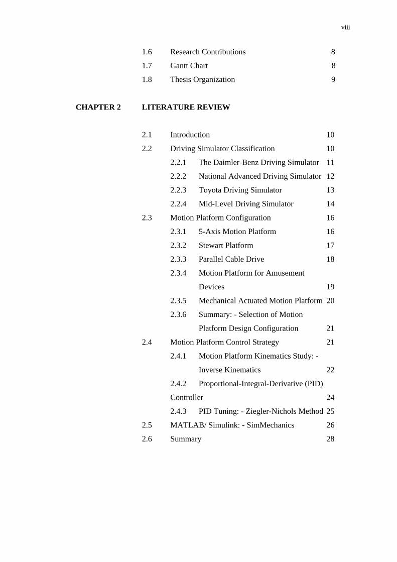
1.6 Research Contributions 8
1.7 Gantt Chart 8
1.8 Thesis Organization 9
CHAPTER 2 LITERATURE REVIEW
2.1 Introduction 10
2.2 Driving Simulator Classification 10
2.2.1 The Daimler-Benz Driving Simulator 11
2.2.2 National Advanced Driving Simulator 12
2.2.3 Toyota Driving Simulator 13
2.2.4 Mid-Level Driving Simulator 14
2.3 Motion Platform Configuration 16
2.3.1 5-Axis Motion Platform 16
2.3.2 Stewart Platform 17
2.3.3 Parallel Cable Drive 18
2.3.4 Motion Platform for Amusement
Devices 19
2.3.5 Mechanical Actuated Motion Platform 20
2.3.6 Summary: - Selection of Motion
Platform Design Configuration 21
2.4 Motion Platform Control Strategy 21
2.4.1 Motion Platform Kinematics Study: -
Inverse Kinematics 22
2.4.2 Proportional-Integral-Derivative (PID)
Controller 24
2.4.3 PID Tuning: - Ziegler-Nichols Method 25
2.5 MATLAB/ Simulink: - SimMechanics 26
2.6 Summary 28

ix
CHAPTER 3 MOTION PLATFORM DESIGN AND SYSTEM
CONFIGURATION
3.1 Introduction 29
3.2 Motion Platform Requirement 29
3.3 Product Design Specification and Limitation 30
3.4 Conceptual Design 34
3.4.1 Design Concept 1 34
3.4.2 Design Concept 2 34
3.4.3 Design Concept 3 35
3.4.4 Design Concept 4 36
3.4.5 Design Concept 5 36
3.5 Design Evaluation 37
3.6 Modifications and Detail Design 38
3.7 Motion Platform System Layout 39
3.8 Summary 41
CHAPTER 4 MOTION PLATFORM MODELING AND SIMULATION
4.1 Introduction 42
4.2 Inverse Kinematic Model (IKM) 42
4.3 Independent Vehicle Dynamic Model 44.
4.4 SimMechanics Motion Platform Generation
Process 46
4.5 Interfacing: - Simulation and Data Acquisition
System 49
4.6 Single Motor Control Model (SMCM) 53
4.7 Motion Platform Graphical User Interface
(MPGUI) 54
4.8 Summary 55

x
CHAPTER 5 RESULTS AND DISCUSSIONS
5.1 Introduction 57
5.2 Inverse Kinematic and SimPlatform Simulation
Results 57
5.2.1 Motion Platform Idle Position 59
5.2.2 Motion Platform Rotational Movement 59
5.2.3 Motion Platform Translational
Movement 61
5.2.4 Motion Platform Combined Motions 63
5.3 Proportional-Integral-Derivative Controller
(PID Controller) Tuning 65
5.3.1 Ziegler-Nichols PID Tuning Results 66
5.3.2 Heuristic Tuning 68
5.4 Actual Motion Platform Simulation 71
5.4.1 Simulink Profiler: - Model
Optimization 71
5.4.2 Motion Platform Hardware and
Simulation Integration 73
5.4.3 Experimental Results on Motion
Cueing 75
5.4.4 Motion Platform Kinematic Calibration
Using Total Station 77
5.4.5 PID Controller for Motion Platform 82
5.4.6 Results of PID Controller for Sinusoidal
Motion Trajectory 84
5.5 Summary 85
CHAPTER 6 CONCLUSION AND RECOMMENDATIONS
6.1 Conclusion 87
6.2 Recommendations 88
REFERENCES 91

xi
APPENDICES A - L 97
LIST OF PUBLICATIONS 221

xii
LIST OF TABLES
TABLE NO. TITLE PAGE
2.1 Ziegler-Nichols PID tuning parameters 26
3.1 Desirable motion platform motion limits 30
3.2 Actuators location calculation 32
3.3 Evaluation criteria 37
5.1 Simulation input 58
5.2 Proportional, Integral and Derivative value for P, PI
and PID controller
65
5.3 Calibration test results 79

xiii
LIST OF FIGURES
FIGURE NO. TITLE PAGE
1.1 Virtual reality fixed-base driving simulator 3
1.2 Fixed-base driving simulator 4
1.3 Design process 5
1.4 Control system design process 6
1.5 Methodology overview 7
1.6 Gantt chart 8
2.1 Driving simulator classification 11
2.2 Daimler-Benz driving simulator with extended
lateral motion system
12
2.3 The NADS in IOWA University 13
2.4 Toyota driving simulator 14
2.5 One of the configuration of 5DT driving simulator 15
2.6 Honda driving simulator 15
2.7 FTM driving simulator 15
2.8 5-axis motion platform 17
2.9 The first flight simulator that uses Stewart platform
for operation
18
2.10 Stewart platform kinematics structure: SPS (Left)
and UPS (Right)
18
2.11 Parallel cable drive motion base prototype 19
2.12 Arrangement of amusement device 20
2.13 Mechanical actuated motion platform 20
2.14 Vector diagrams for Stewart platform 23
2.15 Stewart platform with slider bar control 27
2.16 SimMechanics Stewart platform model 27

xiv
3.1 Vehicle dynamics (Roll, pitch, yaw, surge, sway and
heave)
30
3.2 Workspace of the upper platform 31
3.3 Motion platform side view with estimated
dimensions
31
3.4 Motion platform actuators position from top view 33
3.5 Design concept 1 34
3.6 Design concept 2 35
3.7 Design concept 3 35
3.8 Design concept 4 36
3.9 Design concept 5 37
3.10 Modification of final concept A to B, B to C 38
3.11 Motion platform system layout 40
4.1 Inverse kinematic model (IKM) 43
4.2 Subsystems in inverse kinematic model 44
4.3 iUTMVDM with IKM 45
4.4 CAD to SimMechanics transformation sequence 46
4.5 SimMechanics block model 47
4.6 Motion platform model in CAD and SimMechanics 47
4.7 Setting up the joint actuator block with cylindrical
block
48
4.8 Sequence of motion platform collapsing (without
joint actuator blocks)
48
4.9 Machine environmental block 48
4.10 Complete SimPlatform with inverse kinematic
model
49
4.11 S-function: - a bridge connecting simulation and
hardware
50
4.12 Advantech PCI 1723 - ODAQ 51
4.13 Motor driver - MD30B 51
4.14 Motor driver input signals - PWM and digital 52
4.15 Output signal from PCI 1723 during forward and
reverse actuations
52
xv
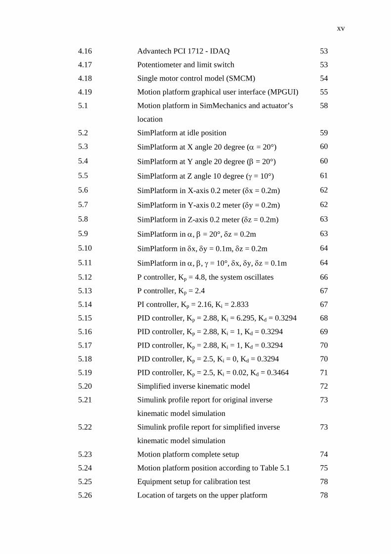
4.16 Advantech PCI 1712 - IDAQ 53
4.17 Potentiometer and limit switch 53
4.18 Single motor control model (SMCM) 54
4.19 Motion platform graphical user interface (MPGUI) 55
5.1 Motion platform in SimMechanics and actuator’s
location
58
5.2 SimPlatform at idle position 59
5.3 SimPlatform at X angle 20 degree (α = 20°) 60
5.4 SimPlatform at Y angle 20 degree (β = 20°) 60
5.5 SimPlatform at Z angle 10 degree (γ = 10°) 61
5.6 SimPlatform in X-axis 0.2 meter (δx = 0.2m) 62
5.7 SimPlatform in Y-axis 0.2 meter (δy = 0.2m) 62
5.8 SimPlatform in Z-axis 0.2 meter (δz = 0.2m) 63
5.9 SimPlatform in α, β = 20°, δz = 0.2m 63
5.10 SimPlatform in δx, δy = 0.1m, δz = 0.2m 64
5.11 SimPlatform in α, β, γ = 10°, δx, δy, δz = 0.1m 64
5.12 P controller, Kp = 4.8, the system oscillates 66
5.13 P controller, Kp = 2.4 67
5.14 PI controller, Kp = 2.16, Ki = 2.833 67
5.15 PID controller, Kp = 2.88, Ki = 6.295, Kd = 0.3294 68
5.16 PID controller, Kp = 2.88, Ki = 1, Kd = 0.3294 69
5.17 PID controller, Kp = 2.88, Ki = 1, Kd = 0.3294 70
5.18 PID controller, Kp = 2.5, Ki = 0, Kd = 0.3294 70
5.19 PID controller, Kp = 2.5, Ki = 0.02, Kd = 0.3464 71
5.20 Simplified inverse kinematic model 72
5.21 Simulink profile report for original inverse
kinematic model simulation
73
5.22 Simulink profile report for simplified inverse
kinematic model simulation
73
5.23 Motion platform complete setup 74
5.24 Motion platform position according to Table 5.1 75
5.25 Equipment setup for calibration test 78
5.26 Location of targets on the upper platform 78

xvi
5.27 Total station positioning system 79
5.28 Motion platform in idle position 80
5.29 Motion platform position when δx = 0.2m 81
5.30 Motion platform position when β = 20° 81
5.31 Motion platform position when γ = 20° 81
5.32 Actuator 1 with PID controller, Kp = 2.5, Ki = 0.02,
Kd = 0.3464
82
5.33 Actuator 1 with P controller, Kp = 1 and ±0.5mm
error band
84
5.34 Actuator 1 motion tracking 85

xvii
LIST OF SYMBOLS/ ABBREVIATION
Pθ - Angles between and (°) 1P 2P
Bθ - Angles between and (°) 1B 2B
Pr - Upper platform radius (m)
Br - Lower platform radius (m)
iP - Location of actuators connections to upper platform
iB - Location of actuators connections to lower platform
α - Roll/ Rotation in X-axis (°)
β - Pitch/ Rotation in Y-axis (°)
γ - Yaw/ Rotation in Z-axis (°)
x - Upper platform position in X-axis (m)
y - Upper platform position in Y-axis (m)
z - Upper platform position in Z-axis (m)
il - Leg/ actuator length (m)
dB - Position of frame {P}
iP p - Vector describing position with respect to frame {P} iP
iBb - Vector describing position with respect to frame {B} iB
iB q - Leg vector with respect to frame {B}
RRP - Orientation matrix with respect to frame {B}
pX - Axis perpendicular to line connecting and 1P 6P
BX - Axis perpendicular to line connecting and 1B 6B
iλ - Angles between and (°) 1PP pX
iΛ - Angles between and (°) 1BB BX

xviii
YR - Rotation matrix (Z-axis)
PR - Rotation matrix (Y-axis)
RR - Rotation matrix (X-axis)
{B} - Frame {B}/ Lower Platform
{P} - Frame {P}/ Upper Platform
CAD - Computer-Aided Design
DAQ - Data Acquisition System
DOF - Degree of Freedom
HYSIM - Highway Driving Simulator
IDAQ - Input Data Acquisition
IKM - Inverse Kinematic Model
iUTMVDM - Independent Universiti Teknologi Malaysia Vehicle
Dynamic Model
LVDT - Linear Variable Differential Transformer
MPGUI - Motion Platform Graphic User Interface
NADS - National Advanced Driving Simulator
ODAQ - Output Data Acquisition
PID - Proportional-Integral-Derivative (Kp, Ki, Kd)
POT - Potentiometer
PWM - Pulse Width Modulation
SimPlatform - SimMechanics Motion Platform
SMCM - Single Motor Control Model
SPS - Spherical-Prismatic-Spherical
TCP/IP - Transmission Control Protocol/ Internet Protocol
TMC - Toyota Motor Corporation
UPS - Universal Joint-Prismatic-Spherical
UTMVDM - Universiti Teknologi Malaysia Vehicle Dynamic Model
VTI - Swedish National Road and Transport Research Institute

xix
LIST OF APPENDICES
APPENDIX TITLE PAGE
A Existing Driving Simulators 97
B Evaluation Chart 100
C Engineering Drawing 103
D Advantech PCI 1723 135
E Electronic Circuit 137
F Motor Driver - MD30B 149
G Advantech PCI 1712 148
H SMCM - S-function 151
I MPGUI - S-function 161
J Kinematic Calibration Test 1, 2, 3 183
K Calibration Results Calculation 202
L Error Band - S-function 208

CHAPTER 1
INTRODUCTION
1.1 Preface
Driving simulator has a history of several decades and has been used widely
throughout the world. One of the earliest driving simulators dated back in 1970s,
when General Motors, Virginia Polytechnic Institute and State University did the
pioneering work on human-in-loop driving simulations [1]. The Federal Highway
Administration driving simulator (HYSIM) begun operation for human factors work
later in 1983 [2]. This is then followed by the development of the VTI driving
simulator with extensive motion system by Swedish National Road and Transport
Institute in Linkoping on 1984 [3]. Other automobile manufacturers and research
institute such as the Daimler-Benz, DRI, Ford Research laboratory and IOWA
University also begun their own driving simulator development since the mid of
1980s.
Driving simulators are often used for educational and research purposes.
Driving simulators’ capability in producing a virtual driving environment resembling
real driving condition can be used to train novice drivers before they are exposed to
the real world [4]. Aside from that, driving simulators are important in data
collection for road safety research, human factor study, vehicle system development
and also traffic control device development [5]. These allow designers, engineers as
well as ergonomists, to bypass the design and development process of detailed

2
mockups of the automobile interiors for human factor and vehicle performance
studies.
1.2 Problem Statement
Road safety has always been a major concern for the Malaysian Government.
The rapid increase in motor vehicle ownership in combination with the relatively
young age of the populations and wide mix of vehicle types in the recent years have
resulted in a significant increase of road safety problems. Various engineering
approaches have been taken by the Government to overcome the problem, including
proactive actions, reactive actions, road maintenance and building new roads [6]. In
conjunction with the effort in the proactive actions, a research in developing a
driving simulator was started in 2002, in Universiti Teknologi Malaysia by the
Engineering Visualisation Research Group (EngViz). The driving simulator will
provide the platform for future research related to road safety and transport. At the
end of the first stage research work, a fixed-base driving simulator with visual
database and a generic vehicle dynamic model [7]. Figure 1.1 shows the result of the
first stage research work. This research work is the second stage and was aimed to
design and integrate a motion platform to the existing fixed-base driving simulator.
While driving a vehicle, a driver experiences the ride and handling characteristics of
the vehicle through motion cues due to angular and linear accelerations of the vehicle
chassis. The motion platform for driving simulator is a mechatronic equipment that
is capable of giving the realistic feeling of an actual vehicle to the drivers [8].
Motion platform varies in design depending on the design configurations, mechanism
used, motion properties and number of degrees of freedom (DOF). To integrate a
motion platform to the fixed-base driving simulator, a suitable motion platform must
be design and construct. This design process involves motion platform mechanism
design and construction, control system design and integration of the motion
platform with the existing driving simulator system. The mechanism design and
construction is aimed to design and construct the actual motion platform which is
suitable for the purposes. Control system design involves the mathematical modeling
and control algorithm development which describes the designed motion platform

3
mathematically and to control it. Finally, the integration work is to combine the
actual motion platform and its mathematical model with the previous fixed-base
driving simulator.
Figure 1.1: Virtual reality fixed-base driving simulator.
1.3 Objective of Study
The objectives of the research are to design and construct a motion platform
and to develop an algorithm of controlling a six degrees of freedom motion platform
for vehicle driving simulator application. The research also verifies and validates the
results based on published journals and simulation package. The motion platform is
aimed to integrate with the fixed-base driving simulator [7] shown in Figure 1.2.
a. Virtual Database
b. Driving Cabin c. Vehicle Dynamic Model

4
Figure 1.2: Fixed-base driving cabin.
1.4 Scope of Study
1. To develop the motion platform mathematical model and system control
using MATLAB/ Simulink.
2. To design and construct motion platform based on 6-DOF.
3. To develop a digital PID algorithm for controlling a 6-DOF motion platform.
4. To verify and validate the motion platform’s motion cues using graphical
display of the motion platform and comparing with actual model.
1.5 Research Methodology
The motion platform development process is divided into three major
components; mechanism design, control system development and system integration.
1.5.1 Mechanism Design
The specification and system requirements of the motion platform design
were first critically reviewed. This is followed by review of various existing motion
platform design configurations. Different motion platform configurations were
studied and analyzed. The most suitable configuration was chosen based on the

5
system requirements developed for this research [9]. Figure 1.3 shows the general
mechanism design process.
Figure 1.3: Design process.
1.5.2 Control System Design
The control system design is aimed to accurately control the 6-DOF motion
platform using Proportional-Integral-Derivative (PID) controller. The motion
platform was first mathematically modeled. From the mathematical model of the
motion platform, the control variable was identified. In this research, the control
variable is the linear motion of the actuation unit for the motion platform. Validation
and verification of the mathematical model was carried out to determine the accuracy
of the mathematical model representing the motion platform. Next is to determine
the control strategy and develop a digital PID algorithm for motion platform.
Simulation was carried out through the assistance of MATLAB/ Simulink. The
performance of the PID controller in the motion platform was then evaluated and
improved. The process of control system design is shown in the Figure 1.4 [10].
Establishing Scopes and Objective
Literature Review
Conceptual Design
Initial Analysis
Final Conceptual Design
Evaluation

6
Figure 1.4: Control system design process.
In addition to the modeling and controller design, the research work also
involves the development of a data acquisition system (DAQ). Generally, data
acquisition is the sampling of the real world to generate data that can be manipulated
by a computer. The data acquisition system is designed to measure and log
parameters. A data acquisition system consists of hardware and software. The
hardware includes sensors, cables and other electronics component. As for the
software components, it consists of the data acquisition logic and the analysis
software. This software can be developed using various programming languages
such as BASIC, C, Fortran, Java or Pascal. Data logging carried out by a data
acquisition system, can be used to measure parameters such as sensor’s voltage
which is the information for motor position. These data are then stored for analysis
to improve the quality of the system [11].
1.5.3 System Integration
The system integration stage is very much dependent on the work done in the
previous two. This stage can only begin when both mechanism design and control
Establishing Goals
Derivation of Mathematical Model
Development of Control Algorithm
Simulation
Evaluation
Validation or Verification

7
system design are done. The developed control system needs to be integrated with
the designed mechanism in order to obtain the desired output of the system.
1.5.4 Summary
The Figure 1.5 shows the summary of the research methodology.
Figure 1.5: Methodology overview.
1.6 Research Contribution
The contributions of this research are:
1. This research is the initial attempt to control the motion platform in real time.
In this research, Proportional-Integral-Derivative control algorithm (PID) is
used and the details will be explained in Chapter 2.
Validation or Verification
Control System Design and Simulation
Integration
Mechanism Design
Design and Development of a 6 DOF Motion Base

8
2. To develop the frame of integrating motion platform with other driving
simulator subsystem such as the visual database and vehicle dynamic model.
3. Acquiring the technology behind the motion platform control and design.
This motion platform was developed from scratch and the use of computer
application software was minimal to avoid ‘black-box’ in the development
process.
1.7 Gantt Chart
This research was scheduled for 18 months duration. Thus careful planning
is required for the research to proceed and to be completed. Figure 1.6 shows the
Gantt chart of the research.
Figure 1.6: Gantt chart.
1.8 Thesis Organization
This thesis is divided into six chapters. The first Chapter gives an overall
introduction of the research project. It consists of preface, problem statement,
objective of study, scope of study and research methodology. The Chapter ends with
Month
Work 1 2 3 4 5 6 7 8 9 10 11 12 13 14 15 16 17 18
Obtain Title & Discuss
Objectives
Literature Studies
Log & Progress Writing
Math Formulation
Modeling
Design Selection & Purchasing
Programming
Control and Construction
Validation and Implementation
Report Writing
9
the research contribution and a Gantt chart showing the planning for the research.
Chapter 2 presents the fundamental concepts and literature review pertaining to the
focus of study. This includes the classification of driving simulators, different
motion platform configurations, and mathematics (kinematics) involved in motion
platform design. A brief review on the simulation software and the control strategy
used is also presented. Chapter 3 focuses on the motion platform mechanism design.
It clarifies the design requirements and design specifications. The conceptual
designs and design evaluation are shown. At the end of Chapter 3, the final design
concept and the motion platform system layout is shown. Chapter 4 discusses
simulation and system integration development process of the inverse kinematic
model, independent vehicle dynamic model, S-function, SimMechanics model,
single motor control model and motion platform Graphical User Interface (MPGUI).
The integration of the control system with the motion platform is also briefly
discussed. Chapter 5 discusses the simulation results together with validations with
real time test results. The PID tuning test results are also shown in Chapter 5. The
complete motion platform system with calibration of the motion cues are presented
in the end of Chapter 5. Finally, Chapter 6 concludes the research and several
recommendations on further research works are given.


![caxapa.rucaxapa.ru/thumbs/771821/Atmel-11289-32-bit-Cortex... · SAM G55 [DATASHEET] 7 Atmel-11289F-ATARM-SAM-G55G-SAM-G55J-Datasheet_27-May-16 PIO Controller - PIOA - PIOB PA0–PA31](https://img.pdfslide.us/doc/110x75/5f05568d7e708231d412789b/sam-g55-datasheet-7-atmel-11289f-atarm-sam-g55g-sam-g55j-datasheet27-may-16-pio.jpg)