Embed Size (px)
Citation preview

sensors
Article
Design of a Planar Array of Low Profile Horns at28 GHz
Jou-Yi Wang, Malcolm Ng Mou Kehn 1 and Eva Rajo-Iglesias 2,∗
1 Department of Electrical and Computer Engineering, National Chiao Tung University,Hsinchu 30010, Taiwan; [email protected] (J.-Y.W.); [email protected] (M.N.M.K.)
2 Signal Theory and Communications Department, University Carlos III of Madrid, 28911 Leganes, Spain* Correspondence: [email protected]
Received: 11 November 2020; Accepted: 1 December 2020 ; Published: 7 December 2020�����������������
Abstract: A planar array of low profile horns fed by a transverse slotted waveguide array in thelow millimeter-wave regime (28 GHz) is presented. The array of transverse slots cannot be directlyused as antenna as it has grating lobes due to the fact that slot elements must be spaced a guidedwavelength. However, these slots can be transformed into low profile horns that with their radiationpatterns attenuate the grating lobes. To this aim, low profile horns with less than 0.6λ0 height weredesigned. The horns include a couple of chips that contribute to further reduce the grating lobesespecially in the H-plane. The good performance of the designed array was demonstrated by bothsimulations and experiments performed on a manufactured prototype. A 5 × 5 array was designedthat has a measured realized gain of 26.6 dBi with a bandwidth below 2%, still useful for someapplications such as some radar systems. The total electrical size of the array is 6.63λ0 × 6.63λ0.The radiation efficiency is very high and the aperture efficiency is above 80%. This all-metal solutionis advantageous for millimeter-wave applications where losses sustained by dielectric materialsbecome severe and it can be easily scaled to higher frequencies.
Keywords: millimeter wave antennas; low profile horns; transverse slotted waveguide arrays;grating lobes
1. Introduction
Slotted-waveguide antenna arrays are endowed with many advantages, such as high gain,high efficiency, good polarization performance with low cross polar radiation, conformality, ease ofmanufacture, and thus cost effectiveness, as well as having mechanisms for the control of radiationproperties (via the slot parameters and orientations) and high power handling capability. This type ofantenna finds important applications in emerging technologies of the millimeter-wave (mm-wave)regime, such as 5G wireless communications, automotive and base station antennas, Internet of Things(IoT), smart cities, and autonomous radar systems [1–3].
Longitudinal slots on the broad-walls of rectangular waveguides have been the prevalentconfiguration for two-dimensional (2D) arrays. By displacing slots from the waveguide axis in astaggered manner and spacing adjacent offset slots by half the guided wavelength along the axis,broadside radiation without grating lobes can be achieved [4]. For transverse slotted waveguidearrays, however, no such simple maneuver by mere arrangements of the slots is feasible. For broadsideradiation, neighboring transverse slots are compelled to be separated by one guided wavelength,leading to a unit-cell period that exceeds the free-space wavelength. As a result, grating lobesinevitably emerge. More complicated options using the narrow-walls of the waveguide have been alsoproposed [5].
Sensors 2020, 20, 6989; doi:10.3390/s20236989 www.mdpi.com/journal/sensors

Sensors 2020, 20, 6989 2 of 15
There have been previous efforts made to alleviate the problem of grating lobes in transversewaveguide slot arrays. Baffles comprising parallel plates to suppress grating lobes were adoptedby Josefsson [6]. The cancellation of reflection by using pairs of slots for transverse slot arrays wasreported by Sakakibara et al. [7]. A straightforward approach of reducing the guided wavelength bypartial filling of the waveguide with dielectric was studied by Joubert [8]. Haron et al. [9] used unequallengths of non-resonant transverse slots contained within a unit cell of period less than the free-spacewavelength for phase compensation. In the spirit of Sakakibara et al. [7], the reduction of reflectionfrom the slot by the use of inductive posts was investigated by Park et al. [10]. These concepts ofreflection cancellation for the mitigation of grating lobes persisted in [11,12], in which parasitic dipolelayers were incorporated over the slot array.
Despite these studies, the suppression of grating lobes in transverse slotted waveguide arraysremain pertinent, especially in the wake of mm-wave architectures that impose ever-increasingdemands for higher gains, channel capacities, and data rates, all of which are in conflict with theaggravated losses at those high frequencies. Many previous approaches for grating lobe reduction haveinvolved dielectric materials, the dissipation through which is particularly severe in the mm-waveregime. This motivates alternative solutions that entail only metallic parts which do not incurdissipating losses at increased frequencies that are as grave as those suffered by dielectric components.
In some recent studies of waveguide slot arrays made entirely of metal [13,14], a one-dimensional(1D) transverse slot array on the broad-wall of a rectangular gap waveguide for broadside radiation at28 GHz was reported, and in which grating lobe suppression was achieved by laying a corresponding1D array of external low profile horns over the slots, constituting an all-metal topology. In other words,the slots are transformed in low profile horns whose radiation patterns act as spatial filters for thegrating lobes, attenuating them. Besides, as horns are non-resonant antennas, they have advantageswhen used in arrays [15].
Extending the latter work, this paper investigates the design of a 2D planar array of low profilehorns fed by a 2D slotted waveguide system. The design is made at 28 GHz, a frequency in the lowmm-wave regime. The transformation of the slots into horns allows the suppressing of grating lobes,not only in E-plane, but in H-plane as well for the original transverse slotted waveguide startingpoint. A relevant remark is that, actually, in H-plane, the inter-element distance of the reference slotscould be set as less than one wavelength. However, with the addition of the horns, there is higherflexibility for the separation also in this plane and in this study we decided to keep the same distancefor the two planes with the purpose of obtaining an almost symmetrical radiation pattern in the twomain planes. The horns are low profile ones (less than 0.6λ0) and modifications of their geometry toachieve a more uniform field distribution in H-plane are presented. Designs by simulations using CSTMicrowave Studio R© (henceforth, just CST) were first performed, followed by experimental validationvia measurements carried out on a manufactured prototype.
A brief outline of the paper is as follows. The designs by simulations of the feed system i.e., the 2Dtransverse waveguide slot array initially without the horns are described in Section 2. This is followedin Section 3 by the presentation of the horn array placed over the radiating waveguide slot array thatis fed in the same way, along with simulation results that demonstrate how the designed horns canmitigate grating lobes. Measurement results of experiments carried out on a manufactured prototypeaccording to the simulated design are given in Section 4. Finally, the paper wraps up with a conclusionthat summarizes the key aspects of the work.
2. Design of the 2D Transverse Waveguide Slot Array
As a first step, the 2D array of transverse slots is designed. The structure is used as the feednetwork of the array of horns. This array consists of transverse slots on the broad-walls of rectangularwaveguides [16] placed side-by-side one another and fed by a single perpendicularly-orientedwaveguide placed beneath (as in [17–19]). A 5 × 5 array is considered in this case, thus entailingfive collated waveguides making up the upper layer and each with five transverse slots cut out of

Sensors 2020, 20, 6989 3 of 15
its upper radiating broad-wall, as well as an underlying feed waveguide with also five slots on itsbroad-wall spaced by a guided wavelength that couple the energy to the five upper collated radiatingwaveguides. A perspective view of the schematic is given in Figure 1. As explained above, the inter-slotseparations in each waveguide (E-plane of the array) coincides with the guided wavelength and as aconsequence exceeds the free-space wavelength. This inter-slot distance determines the size of thehorns used in the array. For 2D periodicity, i.e., for the H-plane, there is a bit more of freedom todecide the distance among rows. However in this case, we decided to feed the structure with anidentical waveguide, i.e., the feed waveguide underneath with transverse slots that is used to feedthe five waveguides also requires an inter-element distance of one guided wavelength. Obviously,a change in the feeding waveguide width could have permitted a closer separation of the slotted rows.In summary, the inter-slot separations are identical in E- and H-planes in this design. This decisionconditions the size of the horns, in this case making them squared.
The feeding structure is designed in a classical way. It starts with the selection of the waveguide,in this case a standard WR-34 waveguide with width a = 8.6 mm and height b = 4.3 mm whoserecommended frequency is from 22.00 to 33 GHz, thereby suiting the presently prescribed 28 GHzoperating frequency. The size of each radiating slot is set as 7.1 mm × 2 mm after initial design bysimulations. As mentioned, located on the upper broad-wall of the underlying waveguide are fivefeeding slots that couple to the upper layer of laterally arranged set of waveguides via one of theirterminal ends. Twenty-five radiating slots are located on the collective radiating planar broad-wallsof the collated waveguides. The TE10 modal guided wavelength is 13.7 mm at 28 GHz for the widthof 8.6 mm. However, upon visual inspection of the simulated interior field distribution along thewaveguide axis, it is observed that one field cycle (guided wavelength) is about 14.2 mm, being aslight shift from the theoretically expected value. This minor shift in guided wavelength is due tothe deviation of the finite structure simulated in the CST software from the infinitely long waveguideassumed in theory. Hence, the inter-slot separation implemented in the simulations is set as 14.2 mmin both planes, and the distance of the terminal slot to the end wall of the waveguide is set as 7.1 mm,being half the guided wavelength. A view of the feed waveguide seen from the inside is given inFigure 2, which reveals the array of transverse slots on the outer side displayed in lighter shade.The circles are just holes for fixing the top layer of the prototype. The total length of the interior ofthe feeding waveguide is 96 mm, which includes the 25- mm length of the adapter. The radiatingwaveguides are placed above the feeding slots, as shown in Figure 3, in which the placements of theselatter relative to the fed ends of the former are portrayed.
Figure 1. Perspective view of the designed 2D transverse waveguide slot array without horns.
As shown in Figure 3, the feeding slots are located at one side of the radiating waveguides ratherthan in the middle. The reason for this is better compatibility between the fields in the feeding slotsand the fields in the upper waveguides, being an outcome based on a thorough process of design bysimulations of the feeding waveguide.
This structure was simulated and optimized as an antenna, although, in the next section, the slotsare transformed into low profile horns. However, the design of this 2D planar slot array guarantees theexcitation of the 25 slots (and, as a consequence, also the 25 horns) with equal amplitude and phase.The structure is well matched and if we observe the radiation patterns we could see the grating lobes

Sensors 2020, 20, 6989 4 of 15
in the two main planes. These results are omitted here but are presented below in the experimentalverification of the antenna.
For the calculation of the directions of the grating lobes, we must consider that the elevationangle θ is measured from the z axis, which, for the present case, is along the axes of the waveguides.For desired broadside main beam with θ0= 90◦, the subscript 0 denoting the dominant 0th-orderFloquet harmonic, these nearest-in undesired lobes appearing in visible space show up towards thedirections predicted by the following relation:
θ±1 = 90◦ ± sin−1 2π/pκ0
(1)
where p = 14.2 mm is the simulated period (or inter-slot spacing along the waveguide axis), κ0 = 2π f /c0
is the free-space wavenumber, and f is the frequency. The ±1 denotes the two higher ordered Floquetharmonics. At f = 28 GHz, the two grating lobes are towards θ = 90◦ ± 49◦ = 41◦ and 139◦ in the twomain planes.
Figure 2. Interior of the feeding waveguide.
Figure 3. Interior of the radiating waveguides.
3. Design of the Horn Structure
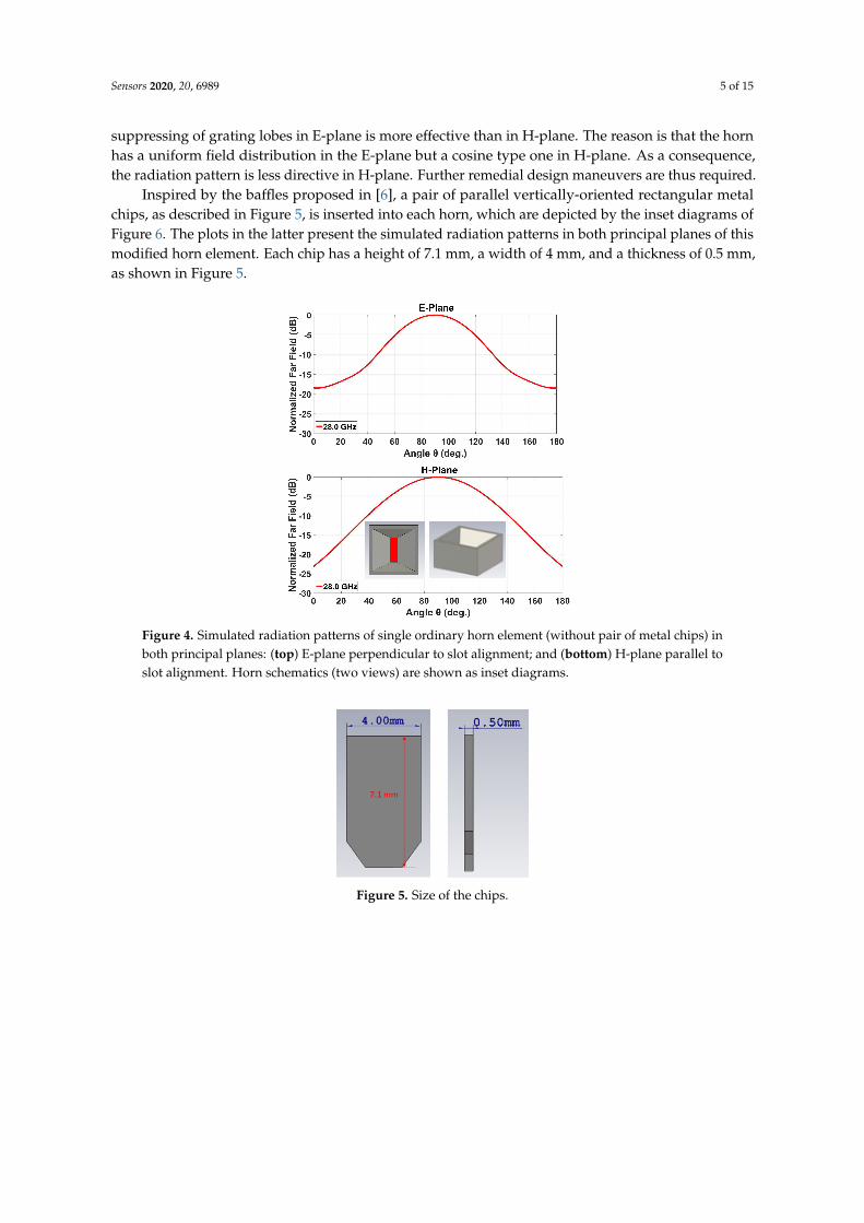
After designing the 2D slotted array, it was used as the feed system for the horns. The rectangularthroat aperture of these pyramidal horn elements takes on the same dimensions as the transverse sloton the broad-wall of the rectangular waveguide, being 7.1 mm × 2 mm as stated above. This slot flareslinearly to a square outermost radiating horn aperture of size 12.2 mm × 12.2 mm. The height of theradiating horn in this case is set to 7.1 mm to keep it low profile following the preliminary design in [13].For a single such horn, the simulated radiation patterns in both principal planes are given in Figure 4,inset diagrams within which depict the structure. As calculated, according to (1), the two gratinglobes of the array are towards 41◦ and 139◦ in both planes. As shown in Figure 4, the anticipatedattenuation of these lobes in E-plane is about 12.5 dB and around 10 dB in H-plane. This means that the
Sensors 2020, 20, 6989 5 of 15
suppressing of grating lobes in E-plane is more effective than in H-plane. The reason is that the hornhas a uniform field distribution in the E-plane but a cosine type one in H-plane. As a consequence,the radiation pattern is less directive in H-plane. Further remedial design maneuvers are thus required.
Inspired by the baffles proposed in [6], a pair of parallel vertically-oriented rectangular metalchips, as described in Figure 5, is inserted into each horn, which are depicted by the inset diagrams ofFigure 6. The plots in the latter present the simulated radiation patterns in both principal planes of thismodified horn element. Each chip has a height of 7.1 mm, a width of 4 mm, and a thickness of 0.5 mm,as shown in Figure 5.
Figure 4. Simulated radiation patterns of single ordinary horn element (without pair of metal chips) inboth principal planes: (top) E-plane perpendicular to slot alignment; and (bottom) H-plane parallel toslot alignment. Horn schematics (two views) are shown as inset diagrams.
Figure 5. Size of the chips.

Sensors 2020, 20, 6989 6 of 15
Figure 6. Simulated radiation patterns of single modified horn element with inserted pair of metalchips in both principal planes: (top) E-plane perpendicular to slot alignment; and (bottom) H-planeparallel to slot alignment. Horn schematics (two views) are shown as inset diagrams.
For the same two grating lobe directions of θ= 41◦ and 139◦, the projected attenuation of theselobes are shown in Figure 6 to be about 30 dB in E-plane and around 17 dB in H-plane, which areconsiderable improvements over the initial horn.
A schematic of the entire 2D transverse waveguide-slot array covered by a planar array of suchspecial pyramidal horn elements with metal chips is illustrated by Figure 7. For this whole structure,the simulated response of the S11 is presented in Figure 8, from which the operating bandwidth isseen to be 27.860–28.246 GHz. The simulated E-plane radiation patterns are provided in Figure 9aand those in H-plane are given by Figure 9b. The grating lobes that would have been present are noweffectively suppressed in both principal planes by the 2D array of external horns, each with a pairof chips, by about 15 dB in E-plane and 10 dB in H-plane at the 28 GHz design frequency. For thewaveguide with horns, the simulated beamwidth is about 7.6◦ in E-plane and 7.5◦ in H-plane at the28 GHz design frequency. The radiation pattern is quite symmetrical. The simulated realized gain isshown in Figure 10 with a maximum of almost 26.6 dBi.
Figure 7. Schematic of the designed structure with horns.

Sensors 2020, 20, 6989 7 of 15
Figure 8. Simulated S11 of the array of horns fed by the 2D transverse waveguide slot array.
(a) E-plane (b) H-plane
Figure 9. Simulated far-field radiation patterns of the 2D transverse waveguide slot array with horns.
Figure 10. Simulated realized gain of the array of horns fed the 2D transverse waveguide slot array asa function of the frequency.
Operation Principle
The fundamentals of the behavior of the new horns and how they deal with the grating lobeattenuation can be explained in different ways. The addition of the chips clearly contributes to makemore uniform the aperture field distribution in H-plane, and as a consequence the horn with chips hasa directivity of 13 dBi, while, without chips, the directivity is 11.5 dBi. This difference is gained bythis design in aperture efficiency. As a consequence, when used in an array, applying the principle ofmultiplication of patterns a higher reduction of the grating lobe will be obtained.
There is another option to explain this improvement by considering the array of horns with andwithout chips and observing their aperture fields. The added pair of parallel metal chips within eachhorn, whose separation dchip = 7.1 mm displacement (perpendicular to the chips) is along the H-plane,produces the effect of reducing the effective electrical (rather than physical) periodicity along theH-plane of the fields on the radiating aperture, to one that equals 7.1 mm, being half of the physicalunit-cell size of 14.2 mm along the H-plane of the structure. The distance between the chips within thesame horn is 7.1 mm and that between two adjacent chips but inside neighboring horns is also 7.1 mm.This halved period then leads to the mitigation of grating lobes in this plane. A similar approach by

Sensors 2020, 20, 6989 8 of 15
using a septum was proposed by Vosoogh et al. [20]. The simulated realized gain of the array of hornsfed by the 2D transverse waveguide slot array as a function of the frequency is presented in Figure 10.
Finally, a comparison of the array with the designed horns with chips with an identical array butwith the conventional low profile horns without chips is presented in Figure 11. The increase in thedirectivity motivated by the evident decrease on the grating lobe levels can be clearly observed inthe figures.
(a) E-plane (b) H-plane
Figure 11. Simulated far-field directivity of the array of horns with and without chips, both fed by the2D transverse waveguide slot array.
4. Experimental Results
In this section, the experimental results of the array of horns which is the focus of this work arepresented. However, we also manufactured and measured one layer corresponding to the planar slotarray, as we can also consider this paper as a contribution to reduce grating lobes in transverse-slottedwaveguide. Besides, the methodology of design of our proposed antenna, i.e., the array of low profilehorns, has as a first step the design of the 2D slotted waveguide. The feed waveguide is a sharedcomponent between the two prototypes, which itself is constructed as a lower and an upper piece,as photographed in Figure 12a, which are screwed together via the sidewalls, a procedure typical ofwaveguide fabrication. For each of the topologies (just slots and horns), the upper layer comprisingthe collated slotted waveguides is likewise fabricated as two separate entities, a lower piece and anupper structure, attachable to each other by screws as well. Clearly, as with the feed waveguide,the lower portion is also common to both configurations. It is the upper part that is distinct betweenthe two: one for the case of horns, as photographed in Figure 12b, and another for the slots, as seen inFigure 12c.
The measured S11 of the manufactured prototype with slots and with horns are presented inFigure 13 over a band centered at the prescribed 28 GHz, alongside the corresponding simulatedresults. Evidently, the designated operation band is realized in the experiments.
Obtained from experiments carried out in an anechoic chamber, photographs of which are shownin Figure 14, the measured far-field normalized radiation patterns in E- and H-planes are presented,respectively, in Figures 15 and 16. Any one subplot within every figure pertains to a certain frequencyas labeled. Two traces are given in each graph, one for the case of the horns and the other for just theslots (named as “without horns”), thereby portraying the effective grating lobe suppression at everyfrequency for both principal planes.
For cases with and without horns, the measured co- and cross-polar radiation patterns in thecentral frequency are presented in Figure 17. As can be seen, the cross polar levels towards the mainbroadside beam direction are raised to about –10 dB, which is due to the modifications of the horns.

Sensors 2020, 20, 6989 9 of 15
(a) Feeding structure (b) with horn
(c) without horn
Figure 12. Photographs of the manufactured prototype.
The measured realized gain of the designed antenna is shown in Figure 18. In the same graph,the measured gain of the array of slots is also represented to show how the reduction of the grating lobesis translated in an average increment of about 7.5 dB in gain over the considered band. The maximummeasured realized gain for the array of low profile horns is 26.3 dB and the simulated directivityis 26.65 dB. The beamwidth of the measured radiation patterns for the waveguide with horns isabout 8 degrees in E-plane and 8.7 degrees in H-plane at the prescribed 28 GHz operating frequency,keeping the symmetry observed in simulations.
Figure 13. Measured and simulated S11 of the 2D transverse waveguide slot array with andwithout horns.

Sensors 2020, 20, 6989 10 of 15
Finally, it is worth mentioning that the measured grating lobe suppression (compared to the caseof the array of slots) in both principal planes is about 15 dB in E-plane and 9 dB in H-plane in the entirefrequency range.
Figure 14. Photographs of experimental setup in anechoic chamber for measurements of far-fieldradiation patterns: (left) without horns; and (right) with horns.
(a) 27.8 GHz (b) 28.0 GHz
(c) 28.2 GHz (d) 28.4 GHz
Figure 15. Measured normalized radiation patterns in E-plane of the 2D transverse waveguide slotarray with and without horns: (a) 27.8 GHz; (b) 28.0GHz; (c) 28.2 GHz; and (d) 28.4 GHz.

Sensors 2020, 20, 6989 11 of 15
(a) 27.8 GHz (b) 28.0 GHz
(c) 28.2 GHz (d) 28.4 GHz
Figure 16. Measured normalized radiation patterns in H-plane of the 2D transverse waveguide slotarray with and without horns: (a) 27.8 GHz; (b) 28.0 GHz; (c) 28.2 GHz; and (d) 28.4 GHz.
(a) For slots (b) For horns
Figure 17. Normalized measured far-field patterns (solid traces, co-polar; dotted traces, cross-polar):(a) for slots; and (b) for horns.
Figure 18. Measured gains of the manufactured 2D transverse waveguide slot array with andwithout horns.
4.1. Antenna Efficiency
Radiation efficiency is typically defined as the ratio between the measured realized gain and thesimulated directivity. In this way, it is a term that accounts for the antenna ohmic losses (dissipation)and mismatch (reflection) losses.

Sensors 2020, 20, 6989 12 of 15
However, when dealing with aperture antennas, another efficiency that is often used is theaperture efficiency. Ideally, this efficiency is the ratio between the antenna directivity and the maximumtheoretical directivity that one antenna with its size can achieve, i.e.,
Dmax = (4π/λ2)S
where S is the physical surface of the antenna.The aperture efficiency is then defined as:
εap = D0/Dmax
where D0 accounts for the classical definition of maximum directivity.Following these definitions, we calculated these two efficiencies, and they are represented in
Figure 19. Here, we also define another efficiency named as “total efficiency” that is the product ofthe other two. The graph of the various sub-efficiencies versus frequency for our antenna array isprovided in Figure 19. At 28 GHz, the achieved approximate 80% total efficiency is about −1 dB, and,because the radiation efficiency that is −0.2 dB at 28 GHz is very high, this total efficiency is alsoalmost the same as the aperture efficiency at that frequency. In other words, the radiation efficiency ofthis antenna is really high and the aperture efficiency is also good.
When compared to the most similar work, i.e., that of Pucci et al. [21], there, an aperture efficiencyof −2.6 dB was reported together with a −1.5 dB of radiation efficiency. The design proposed in thispaper clearly outperforms that one in both efficiencies despite having an operation frequency that isalmost three times the one in [21].
Figure 19. Aperture efficiency and radiation efficiency as a function of the frequency for the low profilehorn array.
4.2. Discussion
The proposed array of low profile horns can be seen as a new contribution following two mainaspects. On the one hand, this can be seen as a technique to reduce grating lobes in transverse slottedwaveguide array and this is the reason we show some results of the array of just slots. Even if thistopic does not have a high impact, it is still deserving of some attention and that can be seen as onemotivation for this contribution. Some examples of techniques to reduce grating lobes can be foundin [22–24].
On the other hand, this is a good antenna design using low profile horns. There are not manyexamples of low profile horns (with less than one wavelength height) in the literature (e.g., [25,26])or something that is not so low in profile but compact (e.g., [27]). These few existing low profilehorns are not used in an array. The only example that we have found of a planar array of low profilehorns is in [21], which is actually the starting point of this work. The designed array here has both ahigher aperture efficiency and a higher radiation efficiency than that in [21] even considering that thefrequency here is almost three times higher. The innovations with respect to the work of Pucci et al. [21]come from the new type of horns that we designed with better aperture efficiency and also from the

Sensors 2020, 20, 6989 13 of 15
type of feed network that we used (a simpler waveguide based feed network compared to an invertedmicrostrip gap waveguide) with the purpose of minimizing the feed network losses. In addition,a linear array of low profile horns (without chips) fed by a transverse slot array was presented by NgMou Kehn and Rajo-Iglesias [14]. However, the horns were not optimized to maximize their directivityand now in the present work, and the addition of the chips allow a further reduction in the gratinglobes. A comparison summary with some related works is presented in Table 1.
As a drawback, the bandwidth is quite limited as it was not the focus of the study, and slottedwaveguide antennas are inherently narrow band. Similar fractional bandwidth percentages can befound in many designs in the literature (see, e.g., [28–30]). However, radio communication systemswith narrow band properties are not so rare, as it is the case of radar systems. Nevertheless, techniquesto improve the bandwidth such as changing the shape of the slots or feeding the waveguides in themiddle could always be applied [31,32].
Table 1. Comparison of performances with related works.
REF. Center Frequency, Undesired Lobe Antenna EfficiencyFractional Bandwidth Suppression (dB) (dB)
[22] no info, 3.4% 8.1 −2.08[24] 76.5 GHz, 1.3% 13.5 no info[21] 10.6 GHz, 11% 8 −4[14] 28.175 GHz, 3% 12 −2.46Ours 28 GHz, 1.38% 15 −1.038
5. Conclusions
A planar array of low profile horns is presented. The design is based on the use of a feed networkthat is a planar array of transverse slots in rectangular waveguide. These slots are transformed in lowprofile horns (with less than 0.6λ0 height), which are specially designed by making use of a coupleof chips, to have more directivity and increase the aperture efficiency of the antenna keeping the lowprofile characteristic. The use of transverse slots is a key point of this design as they perfectly fit forfeeding the horns (it is difficult to imagine a feeding system based on the use of longitudinal slots),and, at the same time, as they have to be separated a distance equal to the guided wavelength, it allowsthe use of horns with a relatively big transverse section.
Designs by simulations led to the manufacture of a prototype, the measurement results of whichagree well with theory, in terms of the operation band, gain, and radiation patterns. The beamwidths ofthe simulated radiation patterns are about 7.5◦ in both principal planes and around 8◦ in measurements.The radiation pattern is quite symmetrical.
The measured gain is above 26 dB and the antenna efficiency is very high. Due to the modificationsof the horns, the cross polar levels towards the broadside main beam direction are slightly increased,which is understandable.
The focus of the study was the design of the array of horns with a feed network made withtransverse slots, however this can also be seen as a technique for mitigation of the grating lobe levelsin transverse slotted waveguide arrays. In this case, the grating lobes are attenuated by about 15 dB inE-plane and around 9 dB in H-plane, which has as a consequence an enhancement on the gains of thebroadside main beams by about 7–7.5 dB, as shown in this study.
This proposed 2D transverse waveguide slot array composed entirely of metal and without anydielectric parts can be applied advantageously to various emerging millimeter-wave technologies.The number of slots can be easily extended to any arbitrary number and the design can be easily scaledto higher frequencies as it is made fully with metal.

Sensors 2020, 20, 6989 14 of 15
Author Contributions: Conceptualization, E.R.-I.; methodology, E.R.-I., M.N.M.K., and E.R.-I.; software, J.-Y.W.;validation, M.N.M.K. and J.W.; formal analysis, M.N.M.K., and E.R.I.; investigation, M.N.M.K., and E.R.I. resources,M.N.M.K. and J.-Y.W.; data curation, M.N.M.K. and J.-Y.W.; writing—original draft preparation, M.N.M.K. andE.R.-I.; writing—review and editing, M.N.M.K. and E.R.-I.; visualization, M.N.M.K. and E.R.-I.; supervision,M.N.M.K. and E.R.-I.; project administration, M.N.M.K. and E.R.-I.; funding acquisition, M.N.M.K. and E.R.-I.All authors have read and agreed to the published version of the manuscript.
Funding: This work was partially supported by the “Center for mmWave Smart Radar Systems and Technologies”under the Featured Areas Research Center Program within the framework of the Higher Education SproutProject by the Ministry of Education (MOE) in Taiwan and partially supported by the Ministry of Science andTechnology (MOST) of Taiwan under Grant numbers MOST 107-3017-F-009-001 and 107-2221-E-009-051-MY2.This work was also partially supported by the Spanish Government with grant numbers: TEC2016-79700-C2-2-Rand PID2019-107688RB-C21.
Conflicts of Interest: The authors declare no conflict of interest.
References
1. Johnson, R.; Jasik, H.; Crawford, H. Antenna Engineering Handbook; McGraw-Hill Handbook; McGraw-Hill:New York, NY, USA, 1984.
2. Park, B.Y.; Im, Y.T.; Park, S.O. Design of a planar slotted waveguide array antenna for X-band radarapplications. J. Korean Inst. Electromag. Eng. Sci. 2011, 11. [CrossRef]
3. Stevenson, A. Theory of slots in rectangular waveguides. J. Appl. Phys. 1948, 19, 24–38. [CrossRef]4. Chen, Z.N.; Liu, D.; Nakano, H.; Qing, X.; Zwick, T. Handbook of Antenna Technologies; Springer: Singapore,
2016; pp. 1–22.5. Oliveira, L.P.; Alves, S.A.M.; Hernandez-Figueroa, H.E. A Novel Vertically Polarized Slotted Waveguide
Array Antenna. In Proceedings of the Second European Conference on Antennas and Propagation, EuCAP,Edinburgh, Scotland, 11–16 November 2007; pp. 1–5.
6. Josefsson, L. A waveguide transverse slot for array applications. IEEE Trans. Antennas Propag. 1993, 41,845–850, [CrossRef]
7. Sakakibara, K.; Hirokawa, J.; Ando, M.; Goto, N. A Linearly-Polarized Slotted Waveguide Array UsingReflection-Cancelling Slot Pairs. IEICE Trans. Commun. 1994, E77-B, 511–518.
8. Joubert, J. A transverse slot in the broad wall of inhomogeneously loaded rectangular waveguide for arrayapplications. IEEE Microw. Guid. Wave Lett. 1995, 5, 37–39. [CrossRef]
9. Haron, S.A.; Koshio, T.; Goto, N.; Hirokawa, J. A Waveguide Slot Antenna for Vertical Polarization.In Proceedings of the IEICE General Conference, September, 2000. Available online: https://ci.nii.ac.jp/naid/10020722185/ (accessed on 6 December 2020).
10. Park, S.; Hirokawa, J.; Ando, M. Simple analysis of a slot and a reflection-canceling post in a rectangularwaveguide using only the axial uniform currents on the post surface. IEICE Trans. Commun. 2003, E86-B,2482–2487.
11. Hossain, M.G.S.; Hirokawa, J.; Ando, M. Parasitic strip dipoles to suppress grating lobes in a waveguidetransverse slot array. In Proceedings of the IEEE Antennas and Propagation Society Symposium, Monterey,CA, USA, 20–25 June 2004; Volume 3, pp. 2376–2379.
12. Hossain, M.G.S.; Hirokawa, J.; Ando, M. Grating lobes suppression in transverse slot linear array with adual parasitic beam of strip dipoles. IEICE Trans. Commun. 2005, E88-B, 2320–2326. [CrossRef]
13. Hsieh, C.; Ng Mou Kehn, M.; Rajo-Iglesias, E. Design of a Transverse Slot Array in Groove Gap Waveguideusing Horns at 28 GHz Band. In Proceedings of the 2019 IEEE International Symposium on Antennas andPropagation and USNC-URSI Radio Science Meeting, Atlanta, GA, USA, 7–12 July 2019; pp. 2045–2046.
14. Ng Mou Kehn, C.K.H.; Rajo-Iglesias, E. Array of Horns Fed by a Transverse Slotted Groove Gap Waveguideat 28 GHz. Sensors 2020, 20, 5311. [CrossRef] [PubMed]
15. Priya, A.H.; Chandu, N.S.; Apoorva, P.; Raghavendra, C. Design and Analysis of Planar Array with HornAntenna Beams. In Proceedings of the 2020 International Conference on Communication and SignalProcessing (ICCSP), Chennai, India, 28–30 July 2020; pp. 0987–0991. [CrossRef]
16. Josefsson, L. (Ed.) Slotted Waveguide Array Antennas: Theory, Analysis and Design; Electromagnetic Waves,Institution of Engineering and Technology: London, UK, 2018.
17. Casula, G.A.; Montisci, G. Design of Dielectric-Covered Planar Arrays of Longitudinal Slots. IEEE AntennasWirel. Propag. Lett. 2009, 8, 752–755. [CrossRef]

Sensors 2020, 20, 6989 15 of 15
18. Rengarajan, S.R. Coupling Between Waveguide-Fed Planar Slot Arrays. IEEE Antennas Wirel. Propag. Lett.2009, 8, 429–432. [CrossRef]
19. Coetzee, J.C.; Sheel, S. Improved Model for Inclined Coupling Slots in the Feed of a Planar Slot Array.IEEE Trans. Antennas Propag. 2020, 68, 1166–1169. [CrossRef]
20. Vosoogh, A.; Kildal, P.; Vassilev, V.; Zaman, A.U.; Carlsson, S. E-band 3-D metal printed wideband planarhorn array antenna. In Proceedings of the 2016 International Symposium on Antennas and Propagation(ISAP), Okinawa, Japan, 24–28 October 2016; pp. 304–305.
21. Pucci, E.; Rajo-Iglesias, E.; Vázquez-Roy, J.; Kildal, P. Planar Dual-Mode Horn Array With Corporate-FeedNetwork in Inverted Microstrip Gap Waveguide. IEEE Trans. Antennas Propag. 2014, 62, 3534–3542.[CrossRef]
22. Trinh-Van, S.; Song, S.C.; Seo, S.; Hwang, K.C. Grating Lobe Reduced Waveguide Slot Array Antenna.In Proceedings of the 2018 International Symposium on Antennas and Propagation (ISAP), Busan, Korea;23–26 October 2018; pp. 1–2.
23. Ripoll-Solano, L.; Torres-Herrera, L.; Sierra-Pérez, M. Design, Simulation and Optimization of a SlottedWaveguide Array with Central Feed and Low Sidelobes. In Proceedings of the 2018 IEEE-APS TopicalConference on Antennas and Propagation in Wireless Communications (APWC), Cartagena, Colombia,10–14 September 2018; pp. 886–889.
24. Araki, T.; Sakakibara, K.; Kikuma, N.; Hirayama, H. Grating lobe suppression of narrow-wall slottedwaveguide array antenna using thin narrow-wall waveguides in millimeter-wave band. In Proceedingsof the 2014 International Symposium on Antennas and Propagation Conference Proceedings, Kaohsiung,Taiwan, 2–5 December 2014; pp. 139–140.
25. Sun, J.; Li, T.; Dou, W.; Meng, H. A Low-Profile Horn Antenna at Ka-Band. In Proceedings of the 2020 IEEEMTT-S International Microwave Workshop Series on Advanced Materials and Processes for RF and THzApplications (IMWS-AMP), Suzhou, China, 29–31 July 2020; pp. 1–3.
26. Moy-Li, H.C.; Sánchez-Escuderos, D.; Antonino-Daviu, E.; Ferrando-Bataller, M. Low-Profile RadiallyCorrugated Horn Antenna. IEEE Antennas Wirel. Propag. Lett. 2017, 16, 3180–3183. [CrossRef]
27. Manshari, S.; Koziel, S.; Leifsson, L. Compact Dual-Polarized Corrugated Horn Antenna for SatelliteCommunications. IEEE Trans. Antennas Propag. 2020, 68, 5122–5129. [CrossRef]
28. Luo, G.Q.; Hu, Z.F.; Dong, L.X.; Sun, L.L. Planar Slot Antenna Backed by Substrate Integrated WaveguideCavity. IEEE Antennas Wirel. Propag. Lett. 2008, 7, 236–239.
29. Mukherjee, S.; Biswas, A.; Srivastava, K.V. Substrate Integrated Waveguide Cavity-Backed Dumbbell-ShapedSlot Antenna for Dual-Frequency Applications. IEEE Antennas Wirel. Propag. Lett. 2015, 14, 1314–1317.[CrossRef]
30. Hwang, J.; Oh, Y. Millimeter-Wave Waveguide Slot-Array Antenna Covered by a Dielectric Slab and ArrayedPatches. IEEE Antennas Wirel. Propag. Lett. 2009, 8, 1050–1053. [CrossRef]
31. Zhao, H.C.; Xu, R.R.; Wu, W. Broadband waveguide slot array for SAR. Electron. Lett. 2011, 47, 76–77.[CrossRef]
32. Pazoki, R.; Rashed-Mohassel, J. Bandwidth Enhancement of Resonant Slot Array Antennas. J. Electromagn.Waves Appl. 2007, 21, 1177–1189. [CrossRef]
Publisher’s Note: MDPI stays neutral with regard to jurisdictional claims in published maps and institutionalaffiliations.
c© 2020 by the authors. Licensee MDPI, Basel, Switzerland. This article is an open accessarticle distributed under the terms and conditions of the Creative Commons Attribution(CC BY) license (http://creativecommons.org/licenses/by/4.0/).


![A 32-GHz Microstrip Array Antenna for Microspacecraft ... · A 32-GHz Microstrip Array Antenna for Microspacecraft Application ... is the planar slotted waveguide array [2], ... posed](https://img.pdfslide.us/doc/110x75/5b344a987f8b9aa0238dc5e2/a-32-ghz-microstrip-array-antenna-for-microspacecraft-a-32-ghz-microstrip.jpg)