Embed Size (px)
Citation preview
Design of a Novel Tripedal Locomotion Robot and Simulation of a Dynamic Gait for a Single Step
By Jeremy R. Heaston
Thesis submitted to the Faculty of the Virginia Polytechnic Institute and State University
in partial fulfillment of the requirements for the degree of Master of Science
In Mechanical Engineering
APPROVED: Dr. Dennis Hong, Advisor Dr. Charles Reinholtz, Committee Member
Dr. Robert Sturges, Committee Member
August 1, 2006 Blacksburg, Virginia
Keywords: Passive dynamics, Bipedal Locomotion, Tripedal Locomotion, Self-excited Actuation

Design of a Novel Tripedal Locomotion Robot and Simulation of a Dynamic Gait for a Single Step
Jeremy R Heaston
Abstract
Bipedal robotic locomotion based on passive dynamics is a field that has been
extensively researched. By exploiting the natural dynamics of the system, these bipedal robots
consume less energy and require minimal control to take a step. Yet the design of most of these
bipedal machines is inherently unstable and difficult to control since there is a tendency for the
machine to fall once it stops walking.
This thesis presents the design and analysis of a novel three-legged walking robot for a
single step. The STriDER (Self-excited Tripedal Dynamic Experimental Robot) incorporates
aspects of passive dynamic walking into a stable tripedal platform. During a step, two legs act
as stance legs while the other acts as a swing leg. A stance plane, formed by the hip and two
ground contact points of the stance legs, acts as a single effective stance leg. When viewed in
the sagittal plane, the machine can be modeled as a planar four link pendulum. To initiate a
step, the legs are oriented to push the center of gravity outside of the stance legs. As the body
of the robot falls forward, the swing leg naturally swings in between the two stance legs and
catches the STriDER. Once all three legs are in contact with the ground, the robot regains its
stability and the posture of the robot is then reset in preparation for the next step.
To guide the design of the machine, a MATLAB simulation was written to allow for
tuning of several design parameters, including the mass, mass distribution, and link lengths.
Further development of the code also allowed for optimization of the design parameters to
create an ideal gait for the robot. A self-excited method of actuation, which seeks to drive a
stable system toward instability, was used to control the robot. This method of actuation was
found to be robust across a wide range of design parameters and relatively insensitive to
controller gains.
iii
Acknowledgements
There has been no shortage of support during my six years at Virginia Tech. I’ve had
many great professors who have shaped me into the engineer that I am today and for that I will
be forever grateful. My advisor, Dr. Dennis Hong, took me on as one of his first grad students.
He saw the potential in me to do some great work and I was fortunate enough to work on such
an interesting project. He developed the Robotics and Mechanisms Lab (RoMeLa) at Virginia
Tech into one of the finest labs at Tech and I consider myself fortunate to be the first to graduate
from it.
On a project that encompasses so many aspects of engineering, it is always a good idea
to make friends with others who have the knowledge that you don’t possess. I was fortunate
enough to have access to some of the best minds at Tech. Ping Ren helped me with a lot of the
dynamics and controls of the STriDER and will continue work on the 3D dynamics and controls
of the STriDER. Ivette Morazzani has helped with the visualization of the STriDER for multiple
steps and will be continuing work on the path planning and kinematics of the STriDER. Robert
Mayo’s help with the electronics and programming of the STriDER has been indispensable.
Without his help there wouldn’t be a working prototype, but rather an elaborate (and rather
expensive) three-legged paperweight. Mark “My Personal Hero” Ingram took many hours out
of his day to make sure I graduated on time. I would return the favor if I had any idea what he
was doing. I’d also like to thank all my labmates and classmates who have given me insight
into the design and implementation of the STriDER and have frequently spent long nights in
the lab helping me troubleshoot. Your contributions have not been forgotten.
I’d also like to thank to students and teachers on my FIRST robotics team for their
continuing support to take on my research projects as their own to help me finish on time.
More notably, thanks to Andersen and Ashley for their help in making the final prototype.
With their help I not only had an amazing looking machine, but also had the time to focus on
the many tasks that were ahead of me.
My family has always supported me from the moment I got to Virginia Tech six years
ago, whether it was through care packages of food so I could survive the long nights of
studying or a little extra cash so I could take a night off and relax. Their abundance of

iv
knowledge on life and their willingness to sit down and listen made even the most stressful of
times easier.
Lastly, I would like to thank my lovely girlfriend Becky for her almost unconditional
love and understanding these past six years. There has been many times during the past two
years, especially, where the stresses of graduate school have been taxing on our relationship,
but she has remained my rock through it all. Any person would be blessed to have such an
amazing person in their lives.

v
Table of Contents
Abstract ............................................................................................................... ii
Acknowledgments ................................................................................................... iii
Table of Contents ................................................................................................. v
List of Tables and Figures ...................................................................................... vii
1 Introduction .............................................................................................................. 1
1.1 Background and Motivation.................................................................... 1
1.2 The Tripedal Locomotion Robot; STriDER .......................................... 3
1.3 Research Objectives………….................................................................. 9
1.4 Thesis Outline............................................................................................. 9
2 Dynamic Simulation and Optimization of Parameters for Design.................... 10
2.1 Modeling of the System............................................................................ 10
2.2 Motion Generation and Control Schemes............................................. 11
2.2.1 Impulse Torque for a Nearly Passive Step……………….. 12
2.2.2 Swing Leg Kipping Motion ………………………………… 13
2.2.3 Knee Backward Swinging Motion ………………………… 14
2.2.4 A Piecewise Active and Passive Approach ………………. 15
2.2.5 Self-Excited Actuation………………………………………. 16
2.3 Parametric Study and Optimization Based on the Self-Excited
Control Model …………………………………………………….......... 18
2.4 Results and Discussions .......................................................................... 20
3 Design of the Tripedal Locomotion Robot .......................................................... 26
3.1 Design Overview of the System……………………………………… 26
3.2 Design of the Knee Joint.......................................................................... 28
3.3 Design of the Three Hip Joints............................................................... 30
3.4 Motor Controller Design and Implementation.................................... 33
3.5 Design Evaluation and Discussion........................................................ 35
4 Experimentation ...................................................................................................... 40
4.1 Testing for Signal Noise Produced by the Slip Ring............................ 40
vi
4.2 Test of the Step Dynamics……………………........................................ 41
4.3 Results and Discussions........................................................................... 44
5 Conclusions and Recommendations ..................................................................... 46
References..................................................................................................................... 48
Appendix A: Lagrangian Dynamics......................................................................... 51
Appendix B: Cost Function Equation ……………………………………………. 61
Appendix C: Material and Parts Suppliers.............................................................. 62
Appendix D: Part Drawings ……………………………………………………… 63
vii
List of Tables and Figures
Figure 1-1: Toy based on passive dynamics patented in 1888……………………… 3
Figure 1-2: McGeer’s model for passive dynamic walker………………………….. 3 Figure 1-3: STriDER: Self-excited Tripedal Dynamic Experimental Robot ………. 4 Figure 1-4. Detailed names of the STriDER joints and links………………………... 5 Figure 1-5: Single step tripedal gait ………………………………………………….. 6 Figure 1-6: Launch and land for long range travel …………………………………. 7 Figure 1-7: In-air deployment ………………………………………………………… 7 Figure 1-8: Tall height of the robot aids in the deployment of sensors at a high position…………………………………………………………………………… 7 Figure 2-1: Multilink pendulum model for the TLR ………………………………… 11 Figure 2-2: Impulse torque model for a nearly-passive step ……………………….. 13 Figure 2-3: Kipping motion used to impart kinetic energy to the system by kicking the swing leg ……………………………………………………………………. 14 Figure 2-4: Knee backward locomotion was developed to prevent the foot from impacting the ground as it passes the stance leg ……………………………………... 15 Figure 2-5: Locomotion strategy that alternates between active and passive joints. Arrows represent active joints………………………………………………….. 15 Figure 2-6: Self-excited model developed by Ono …………………………………... 16 Figure 2-7: Simplification to the four link TLR model that allowed for the application of the self-excited controller……………………………………………….. 17 Table 2-1. Cost function criteria explained……………………………………………. 19 Figure 2-8: Flowchart demonstrating how the design parameters were optimized for the TLR………………………………………………………………………………… 20 Table 2-2: Parameters for the STriDER ……………………………………………….. 21
viii
Figure 2-9: Animation of a single step for the TLR with a time step of 0.1 seconds. Total step time is 0.73 seconds…………………………………………………………… 21 Figure 2-10: Foot clearance versus change in l3 ………………………........................... 22
Figure 2-11: Vertical velocity of the foot versus change in l3…………………………. 23 Figure 2-12: Foot clearance versus change in l4………………………………………… 23 Figure 2-13: Vertical velocity of the foot versus change in l4…………………………. 24 Figure 2-14: Foot clearance versus change in c4………………………………………... 24 Figure 2-15: Vertical velocity of the foot versus change in c4…………………………. 25 Figure 3-1: Drawing of the STriDER, including a polycarbonate hexagonal body…. 27 Figure 3-2: Schematic of knee design……………………………………………………. 29 Figure 3-3: Rendering of the design, complete with pieces that join the leg links to the joint……………………………………………………………………………... 29 Figure 3-4: The centers of rotation of the two adjoining hip joints are in line, allowing for rotation about a common center line………………………………… 30 Figure 3-5: Cyclic motion for multiple steps. Each configuration for a step is represented by a dashed line……………………………………………………………… 31 Figure 3-6: The pan and tilt unit (left) was used for testing of the motor controller. The lower half of the unit is shown on the right ………………………………………... 32 Figure 3-7: Rendering of the hip joint, which allows for continuous rotation of the body…………………………………………………………………………………... 32 Figure 3-8: Final design of the hip joint which allows for three degrees of freedom 33 Figure 3-9: ESV10 Servo Motor Controller measures only 0.95” x 1.4” ……………… 34 Figure 3-10: Example of an idealized point approximation of a θ trajectory………… 34 Figure 3-11: The motor controllers for the swing leg were positioned at the hip…… 35 Figure 3-12: Problem areas in the knee joint……………………………………………. 36 Figure 3-13: Redesign of the knee joint incorporates a keyway to prevent the sun gear from slipping and a lower structure (blue) made from a single piece of material 37
ix
Figure 3-14: The current output shaft is 3mm in diameter, making it difficult to securely affix a gear or coupler shaft to it………………………………………………. 38 Figure 3-15: The machining of a new output shaft, while difficult, could alleviate many of the problems of the current design……………………………………………. 38 Figure 4-1a: Frequency response without a slip ring ………………………………… 41 Figure 4-1b: Frequency response with a slip ring at low RPMs …………………….. 41 Figure 4-2a: Hip rotator profile generated during testing ……………………………. 43 Figure 4-2b: Hip rotator profile generated in the simulation ………………………... 43 Figure 4-3: Hip rotator profile generated during testing …………………………….. 43 Figure 4-4a: Hip rotator profile generated during testing …………………………… 44 Figure 4-4b: Hip rotator profile generated in the simulation ……………………….. 44 Figure A-1: Configuration of the four-link pendulum ……………………………….. 51 Figure D-1: Motor mount for the knee ………………………………………………… 63 Figure D-2: Bevel gear mount for the knee …………………………………………… 64 Figure D-3: Hip rotator joint …………………………………………………………… 64 Figure D-4: Hip flexure joint …………………………………………………………… 65 Figure D-5: Motor casing ……………………………………………………………….. 65 Figure D-6: Body plate with holes for the sliprings ………………………………….. 66
1
Chapter 1
Introduction STriDER (Self-excited Tripedal Dynamic Experimental Robot) is a novel three-legged
walking machine that exploits the concept of actuated passive dynamic locomotion to
dynamically walk with high energy efficiency and minimal control. Unlike other passive
dynamic walking machines, this unique tripedal locomotion robot is inherently stable with its
tripod stance, can change directions, and is relatively easy to implement, making it practical to
be used for real life applications.
Chapter 1 presents the motivation of this research and background information on
passive dynamic locomotion as it has been applied to bipedal robots and swing up robots, such
as the Acrobot. Then, the concept of the unique locomotion strategy of STriDER will be
discussed. Lastly, the research goals and approach and an outline of the thesis are presented.
1.1 Background and Motivation Using legs is the predominant method of moving for animals on land. Research into
legged locomotion is motivated by what is observed in nature. Legged vehicles have the
advantage over wheeled vehicles by having discontinuous contact with the surface [1]. In
addition, legged vehicles can step over obstacles and climb up steep inclines which might be
impassible by wheeled vehicles [2, 3].
Over the past two decades, there has been extensive research into a variety of multi-
legged robots designed for navigating unstructured environments. The Adaptive Suspension
Vehicle [4] from Ohio State University, the volcano exploration robot Dante II [5], Odex I [6]
from Odetics, Inc., and the robot Ambler [7] for planetary surface exploration are good
examples of six-legged hexapods that are designed to traverse uneven terrain. The quadruped
TITAN VII [8], developed for performing construction work on steep inclined construction sites
is an example of a four-legged robot. However, most legged machines with four or six legs
2
move by using gaits based on static stability criteria to walk. This method maintains constant
static equilibrium throughout its motion, making it slow and mechanically complex.
Recent developments in bipedal robots based on dynamic walking, like the humanoid
robots by Honda [9] and Sony [10], have demonstrated that unlike hexapods and quadrupeds,
bipedal robots have the potential to be fast and more energy efficient than robots based on
statically stable walking. However, these bipedal robots require more sophisticated control
methods since the bipedal robots do not have sufficient legs to maintain the body in a statically
stable posture during locomotion. The zero point moment (ZMP) method [11] and various
model-based control methods that model the body as an inverted pendulum [12, 13] are
examples of strategies used to generate a stable walking gait for bipedal locomotion. Many
bipedal robots developed today are based on the trajectory control of the joints [9], consuming
more than 20 times the power of a walking human of the same size [11] making them
energetically inefficient. The actuators of these bipedal robots force the joints through a
computed trajectory that maintains the static equilibrium of the system. Although testing of the
STriDER will implement some form of trajectory following, its trajectory is based on the
dynamics of the system which makes it more closely related to actuated passive dynamic
systems.
Although not formally developed as a useful means of locomotion, the concept of
passive dynamics has been around since the 1800s. The earliest walking machines were simple
toys like the ones shown in Figure 1-1. Since the introduction of passive dynamic walking by
Tad McGeer [14] in the late 1980s, a new philosophy in the control and design of bipedal
walking machines is being explored. Passive dynamics utilizes the natural built in dynamics of
the robot’s body and limbs to create the most efficient walking and natural motion. His robots,
similar to the design shown in Figure 1-2, demonstrated how proper mechanical design of a
robot can provide energy efficient locomotion without sophisticated control methods, the
concept of which is affecting how actuated bipedal robots are being designed and controlled
[16,21]. The validity of the concept of passive dynamic locomotion is evident by the numerous
examples of passive dynamic walkers that function with little actuation and no control [14-20].
Although the concept of passive dynamics is well developed, the implementation of such a
control is a challenge. The tasks of getting all the parameters (dimensions, mass properties, etc.)
3
to be precise for a stable gait cycle are difficult and usually rely on systematic changes of a
physical model rather than parameters developed through analytical methods [22].
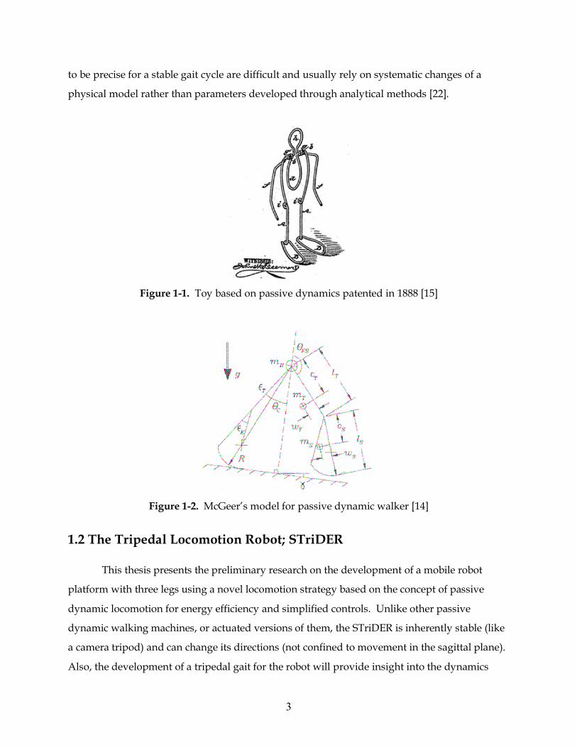
Figure 1-1. Toy based on passive dynamics patented in 1888 [15]
Figure 1-2. McGeer’s model for passive dynamic walker [14]
1.2 The Tripedal Locomotion Robot; STriDER This thesis presents the preliminary research on the development of a mobile robot
platform with three legs using a novel locomotion strategy based on the concept of passive
dynamic locomotion for energy efficiency and simplified controls. Unlike other passive
dynamic walking machines, or actuated versions of them, the STriDER is inherently stable (like
a camera tripod) and can change its directions (not confined to movement in the sagittal plane).
Also, the development of a tripedal gait for the robot will provide insight into the dynamics
4
legged locomotion in general. The scope of this research is to develop the dynamic model of the
STriDER taking a single-step to allow for a parametric study for the optimal design, and to
fabricate a prototype.
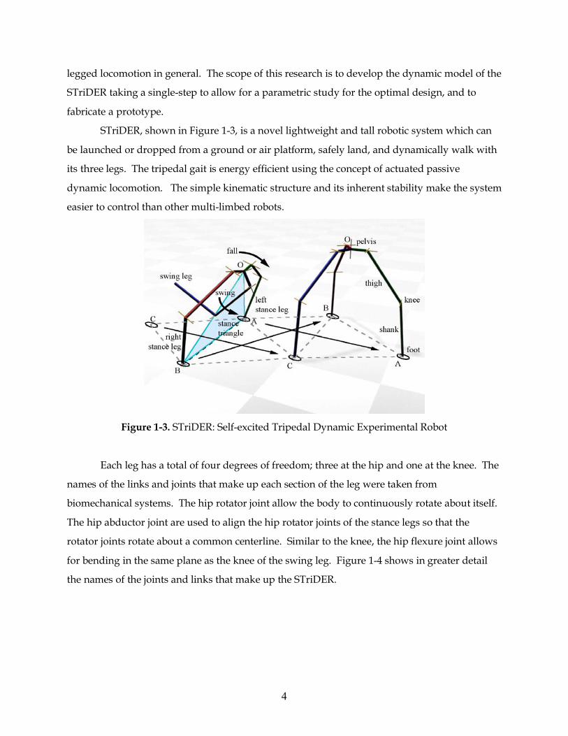
STriDER, shown in Figure 1-3, is a novel lightweight and tall robotic system which can
be launched or dropped from a ground or air platform, safely land, and dynamically walk with
its three legs. The tripedal gait is energy efficient using the concept of actuated passive
dynamic locomotion. The simple kinematic structure and its inherent stability make the system
easier to control than other multi-limbed robots.
Figure 1-3. STriDER: Self-excited Tripedal Dynamic Experimental Robot
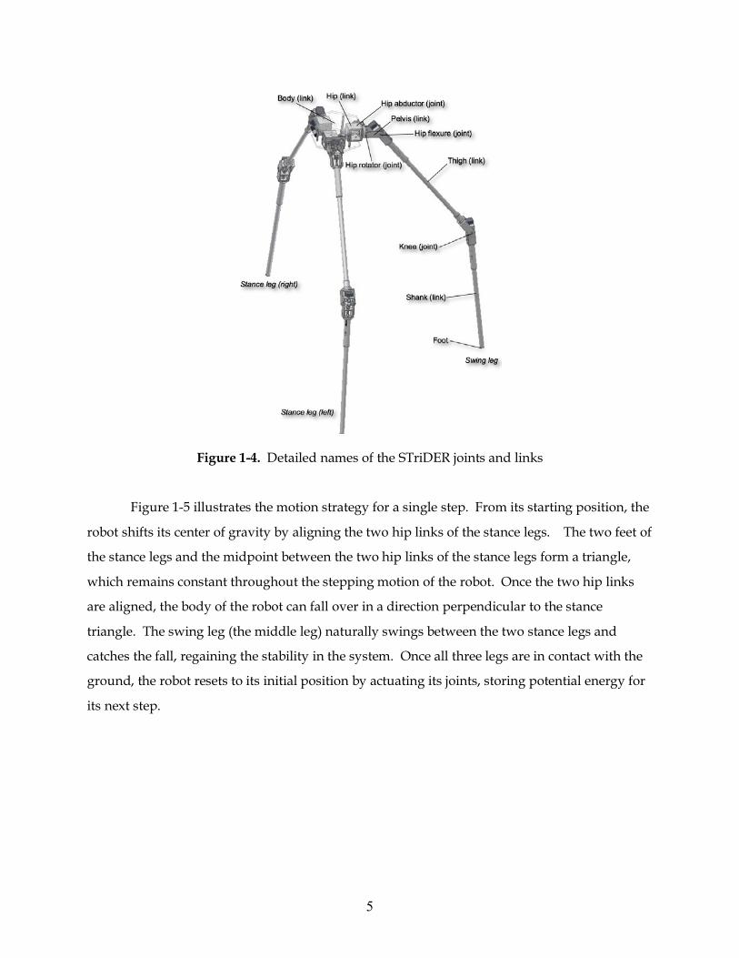
Each leg has a total of four degrees of freedom; three at the hip and one at the knee. The
names of the links and joints that make up each section of the leg were taken from
biomechanical systems. The hip rotator joint allow the body to continuously rotate about itself.
The hip abductor joint are used to align the hip rotator joints of the stance legs so that the
rotator joints rotate about a common centerline. Similar to the knee, the hip flexure joint allows
for bending in the same plane as the knee of the swing leg. Figure 1-4 shows in greater detail
the names of the joints and links that make up the STriDER.
5
Figure 1-4. Detailed names of the STriDER joints and links
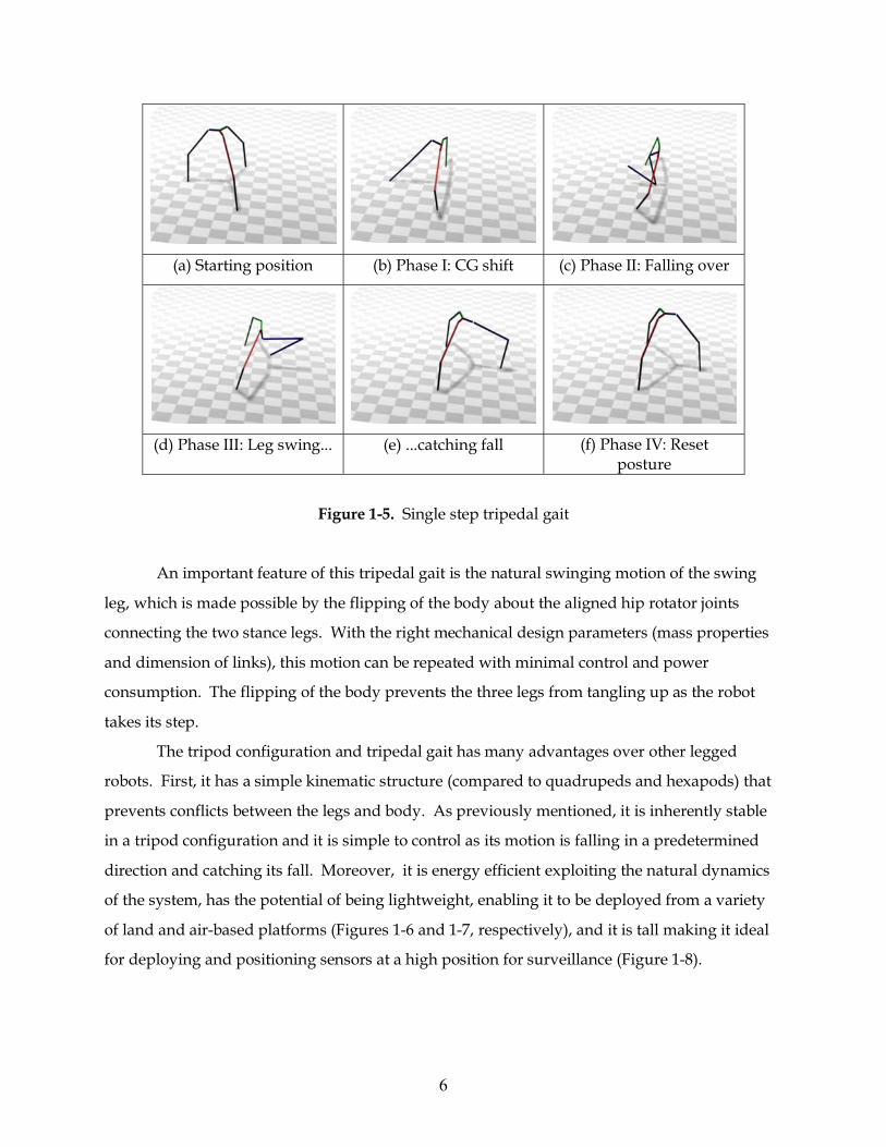
Figure 1-5 illustrates the motion strategy for a single step. From its starting position, the
robot shifts its center of gravity by aligning the two hip links of the stance legs. The two feet of
the stance legs and the midpoint between the two hip links of the stance legs form a triangle,
which remains constant throughout the stepping motion of the robot. Once the two hip links
are aligned, the body of the robot can fall over in a direction perpendicular to the stance
triangle. The swing leg (the middle leg) naturally swings between the two stance legs and
catches the fall, regaining the stability in the system. Once all three legs are in contact with the
ground, the robot resets to its initial position by actuating its joints, storing potential energy for
its next step.
6
(a) Starting position (b) Phase I: CG shift (c) Phase II: Falling over
(d) Phase III: Leg swing... (e) ...catching fall (f) Phase IV: Reset
posture
Figure 1-5. Single step tripedal gait
An important feature of this tripedal gait is the natural swinging motion of the swing
leg, which is made possible by the flipping of the body about the aligned hip rotator joints
connecting the two stance legs. With the right mechanical design parameters (mass properties
and dimension of links), this motion can be repeated with minimal control and power
consumption. The flipping of the body prevents the three legs from tangling up as the robot
takes its step.
The tripod configuration and tripedal gait has many advantages over other legged
robots. First, it has a simple kinematic structure (compared to quadrupeds and hexapods) that
prevents conflicts between the legs and body. As previously mentioned, it is inherently stable
in a tripod configuration and it is simple to control as its motion is falling in a predetermined
direction and catching its fall. Moreover, it is energy efficient exploiting the natural dynamics
of the system, has the potential of being lightweight, enabling it to be deployed from a variety
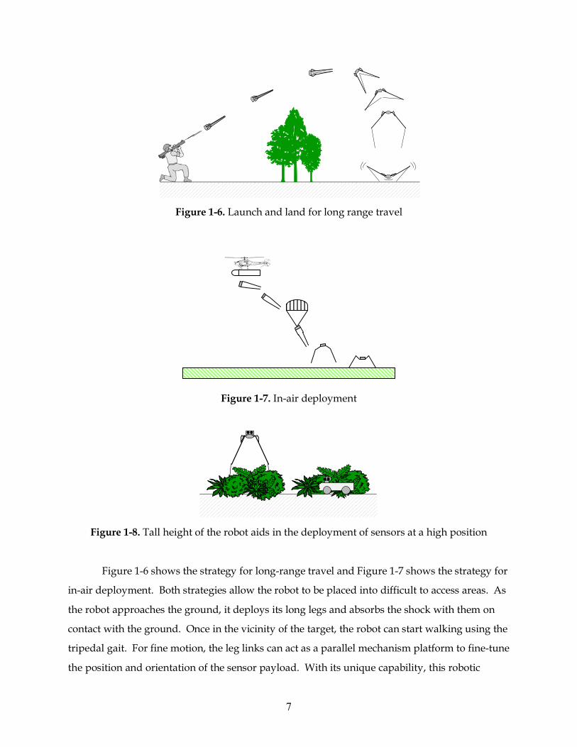
of land and air-based platforms (Figures 1-6 and 1-7, respectively), and it is tall making it ideal
for deploying and positioning sensors at a high position for surveillance (Figure 1-8).
7
Figure 1-6. Launch and land for long range travel
Figure 1-7. In-air deployment
Figure 1-8. Tall height of the robot aids in the deployment of sensors at a high position
Figure 1-6 shows the strategy for long-range travel and Figure 1-7 shows the strategy for
in-air deployment. Both strategies allow the robot to be placed into difficult to access areas. As
the robot approaches the ground, it deploys its long legs and absorbs the shock with them on
contact with the ground. Once in the vicinity of the target, the robot can start walking using the
tripedal gait. For fine motion, the leg links can act as a parallel mechanism platform to fine-tune
the position and orientation of the sensor payload. With its unique capability, this robotic
8
system can be used for many application areas such as environmental monitoring and
protection, sensor deployment for intelligence collection and communication, reconnaissance
and surveillance, or remote detection and neutralization of explosive devices.
There has not been a significant amount of research done on three-legged robots. One
such robot momentarily lifts its leg off the ground and inches forward [23]. This robot was
developed to study genetic algorithms to find the optimum walking pattern for legged robots.
Other locomotion options suggested for another three-legged robot [26], developed as a base
module unit for a modular robot system, include using caster wheels attached to the body, or
crawling by resting its body on the ground and repositioning its limbs to inch forward.
Although these robots are morphologically three-legged robots, their locomotion strategies are
either inferior to other more common strategies such as statically stable alternating tripod gaits
or bipedal walking, or not considered walking at all. Hirose [24] presents a study of a three-
legged gait under the assumption that one leg of a quadruped-walking robot is missing. The
proposed “kick and swing gait” is shown to be a reasonable gait for three-legged walking, but
to be used only for emergency situations. In [25], a virtual environment with artificial evolution
is constructed to evolve behaviors for legged robots and non-biometric locomotion. A three
legged creature was tested in the hope for a successful tripedal locomotion pattern and some
behaviors resembling the kick and swing gait reported by [24] were observed.
These few three-legged gaits proposed so far have both problems of dynamic biped gaits
(robot dynamic model) and static quadruped gaits (leg sequence, footholds, and constraints of
working area) resulting in a planning problem with unique characteristics. Lee and Hirose [24]
argue that a walking robot with three legs has no advantage over bipedal robots quadruped
robots from the standpoint of walking capability and operation ability for these reasons. This
may be true for the few tripedal gaits proposed and studied so far [23-26]. It is the researcher’s
opinion that the reason more work has not been done on three legged robot locomotion is not
because of its inferiority to other means of locomotion as suggested [24], but rather because of
the fact that no creatures in nature have three legs. It is hard to think of a locomotion pattern
for a leg configuration that is not present in nature as most mobile robot concepts that do not
utilize wheels for locomotion are biologically inspired. To walk effectively with three legs,
continuous rotation is required at certain joints to prevent the legs from getting tangled, and
biological systems cannot provide such continuous rotational movement between the body and
9
the members – perhaps one of the reasons why we do not see wheels in nature even though it is
a very efficient means of moving.
Locomotion with a three legged configuration is a new area that has not been fully
explored and is a strategy with great potential as it has the benefits of the stability and ease of
control of hexapods while being energy efficient like the passive dynamic walkers by utilizing
the built in dynamics in their mechanical design.
1.3 Research Objectives
The goal of the project is to initiate the preliminary research for developing and
evaluating the novel tripedal locomotion robot that exploit the principles of actuated passive
dynamic locomotion. The tasks of the research are:
1. Analyze the 2D (sagittal plane) kinematics and dynamics of a single step of the tripedal
locomotion robot and develop mathematical models for simulation.
2. Find the optimal mechanical design parameters (link lengths, mass distribution, etc) that
allow for energy efficient locomotion and simple control with dynamic considerations.
3. Design and fabricate a working robot prototype of the tripedal robot to verify our
analytical model and to evaluate the concept.
The prototype will be used as a test bed for other research projects in the Robotics and
Mechanisms Lab at Virginia Tech. Future research will focus on the 3D kinematics and
dynamics, path planning, and advanced control methods of the STriDER.
1.4 Thesis outline The thesis begins by explaining how the STriDER was modeled and then goes through
the Lagrangian dynamics, which lead to the equations of motion for the system. It then
discusses the general structure of the MATLAB simulation and steps through the optimization
process of the link length ratio. Next, the design of the knee and hip joints will be discussed.
Finally, the thesis covers the implementation of the motor controllers into the STriDER.
10
Chapter 2
Dynamic Simulation and Optimization of Parameters for
Design
A simulation of the dynamic motion for a singe step of the tripedal gait was developed
to aide in the design of STriDER. The goal of the simulation was to optimize several design
parameters, such as link length and mass distribution, to create an ideal single step. This
section will discuss how the STriDER is modeled, how the MATLAB simulation was developed,
and how the model was simplified so that the design parameters could be optimized. The
methods and results of the optimization of the STriDER will then be discussed.
2.1 Modeling of the System
STriDER was modeled as an inverted four-link pendulum with three actuated degrees of
freedom at the joints and one free degree of freedom at the interface between the foot and the
ground. The model can be described by its link lengths, li, its masses, mi, and its center of
gravity location, ci, measured from the intersection of link i and i-1 (the ground is considered in
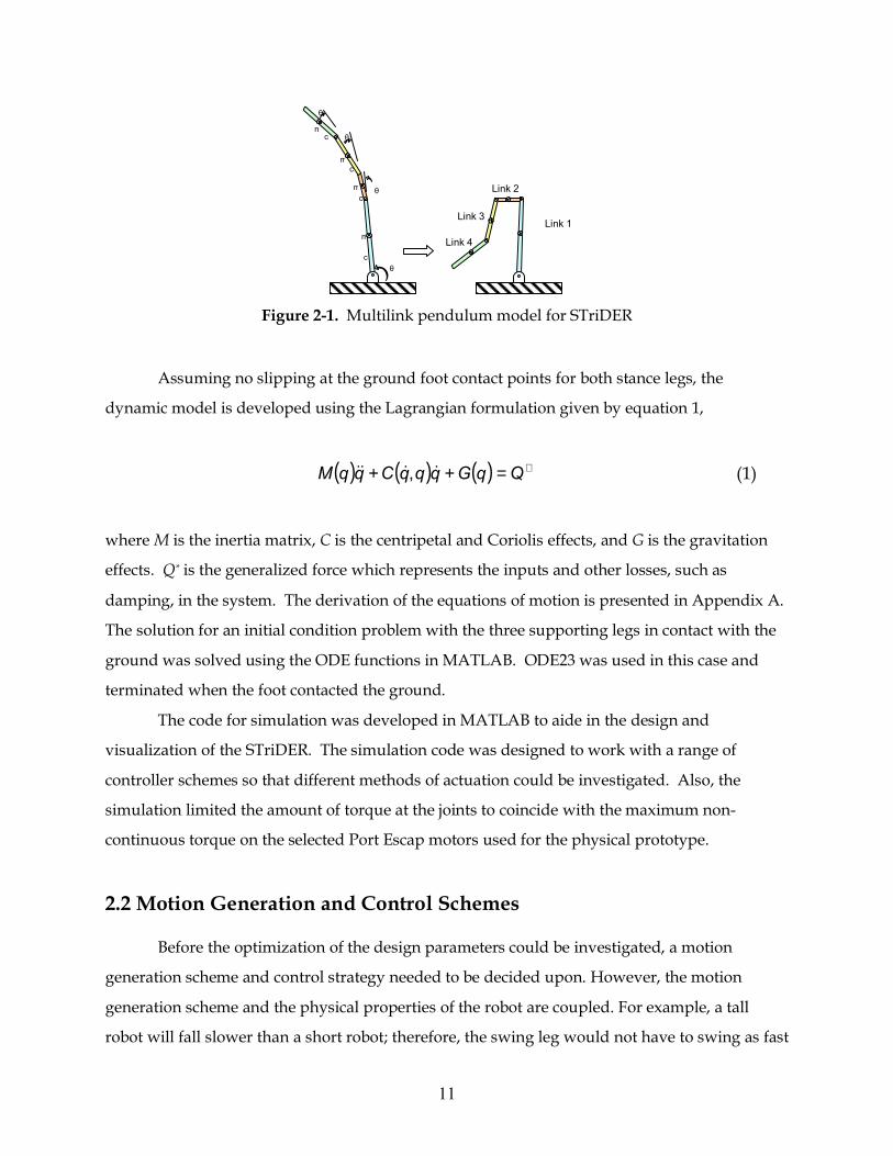
this case to be link 0). Figure 2-1 illustrates the model used. The mass properties of the links
will be measured on a scale once a prototype is built. Moment of inertia values and the location
of the center of gravity will be calculated from the 3D CAD models using the mass properties
function in Autodesk Inventor.
11
Figure 2-1. Multilink pendulum model for STriDER
Assuming no slipping at the ground foot contact points for both stance legs, the
dynamic model is developed using the Lagrangian formulation given by equation 1,
( ) ( ) ( ) ∗=++ QqGqqqCqqM &&&& , (1)
where M is the inertia matrix, C is the centripetal and Coriolis effects, and G is the gravitation
effects. Q* is the generalized force which represents the inputs and other losses, such as
damping, in the system. The derivation of the equations of motion is presented in Appendix A.
The solution for an initial condition problem with the three supporting legs in contact with the
ground was solved using the ODE functions in MATLAB. ODE23 was used in this case and
terminated when the foot contacted the ground.
The code for simulation was developed in MATLAB to aide in the design and
visualization of the STriDER. The simulation code was designed to work with a range of
controller schemes so that different methods of actuation could be investigated. Also, the
simulation limited the amount of torque at the joints to coincide with the maximum non-
continuous torque on the selected Port Escap motors used for the physical prototype.
2.2 Motion Generation and Control Schemes Before the optimization of the design parameters could be investigated, a motion
generation scheme and control strategy needed to be decided upon. However, the motion
generation scheme and the physical properties of the robot are coupled. For example, a tall
robot will fall slower than a short robot; therefore, the swing leg would not have to swing as fast
m
θ
θ
c
cm
m
mθ
θ
c
c
Link 2
Link 1Link 3
Link 4
12
in order to catch itself. Similarly, the shorter robot would have to take a fast step in order to
catch itself. Thus the motion generation scheme needed to be general enough to work with any
combination of parameters inside the design space. In order to test the various strategies a
MATLAB simulation was developed.
This section will present the different motion generation and control schemes that were
investigated for a single step tripedal gait. It should be noted that in this sections words such as
active and passive will be used to describe the joints on the STriDER. This is a bit misleading, as
all the joints (both active and passive joints) will be actively controlled by a motor using a
proportional differential (PD) controller. The passive joints will be driven to match the motion
profile of a completely passive link as it is derived in the MATLAB simulations. In this sense,
the motors are not physically driving the links and thus theoretically, no energy is inputted into
the system. This implementation is done for robustness against external disturbances to
prevent it from collapsing, and to guarantee the robot will remain standing at the end of the
step as the foot hits the ground.
2.2.1 Impulse Torque for a Nearly-passive Step
The first approach was to store potential energy into torsional springs at the hip rotator
joints using motors and then use these wound up springs to actuate the rotator joints, instead of
using the motors to directly drive the joints. The energy inputted into the system would be
stored as potential energy and released fully as kinetic energy. This would potentially
maximize the energy efficiency of the system and would allow for a nearly passive step.
Various steps could be generated by varying the amount of potential energy and would allow
the natural dynamics of the robot to generate the joint motions instead of applying a controller
which drives the links through prescribed joint trajectories. Another advantage of this
approach is that the amount of control required is only slightly more complex than that of a
passive dynamic walker since the motion of the step is governed by the natural dynamics of the
system. However, the design parameters such as mass properties and link lengths need to be
set properly to enable the desired motion of the single step gait.
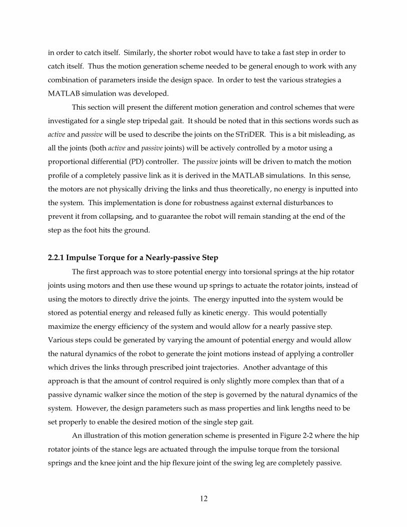
An illustration of this motion generation scheme is presented in Figure 2-2 where the hip
rotator joints of the stance legs are actuated through the impulse torque from the torsional
springs and the knee joint and the hip flexure joint of the swing leg are completely passive.
13
Several simulations of this approach were run and the results were promising. However,
ultimately, this idea was abandoned due to the complexity of the design. This method of
actuation is worth revisiting in future research.
Figure 2-2. Impulse torque model for a nearly-passive step
2.2.2 Swing Leg Kipping Motion
The mechanics by which the STriDER takes a single step are not governed solely by the
constraints of passive dynamic walkers. There has been an extensive amount of research on the
swing up strategies of the Acrobot robot [28]. The key to this strategy used for this motion is
the kip, which is similar to the motion used to build up speed on a swing. This concept was
adapted to fit the locomotion scheme of the STriDER for this motion generation approach. The
STriDER would begin in an upright posture and proceed to bring back the shank of the swing
leg, bending at the knee. The STriDER would push off the ground and begin to fall forward.
Then, the shank would be forced down and forward while the knee straightened out,
performing a kipping motion. The motion of the swing leg would then pull the stance legs
forward while a torque applied at the knee would get the swing leg in a position to impact the
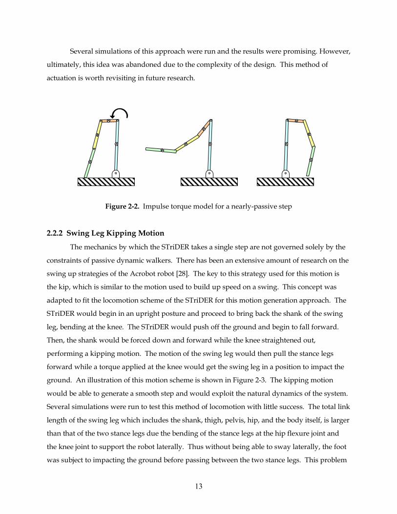
ground. An illustration of this motion scheme is shown in Figure 2-3. The kipping motion
would be able to generate a smooth step and would exploit the natural dynamics of the system.
Several simulations were run to test this method of locomotion with little success. The total link
length of the swing leg which includes the shank, thigh, pelvis, hip, and the body itself, is larger
than that of the two stance legs due the bending of the stance legs at the hip flexure joint and
the knee joint to support the robot laterally. Thus without being able to sway laterally, the foot
was subject to impacting the ground before passing between the two stance legs. This problem
14
could be fixed by driving the shank to greater angles by bending the knee of the swing leg
more, which resulted in an unnatural motion and the inability of the robot to regain its stability
at the end of a step.
Figure 2-3. Kipping motion used to impart kinetic energy to the system by kicking the swing leg
2.2.3 Knee Backward Swinging Motion
A motion generation scheme, the knee backward swing, similar to the motion used to
generate momentum on a swing was investigated to try and prevent the foot from impacting
the ground. This motion requires two input torques at the hip rotator joints of the stance legs
and the knee joint of the swing leg. At the start of the swing, the hip rotator joints are actuated,
bringing the foot of the swing leg off the ground. The knee joint of the swing leg is then
actuated such that the shank swings forward (rather than backward). The combination of the
kicking motion of the shank and the torque at the hip rotator joint is similar to the swinging
action of a human on a swingset. Upon clearing the stance leg, a counterclockwise torque is
applied to the knee to bring the shank of the swing leg into a position to impact the ground. An
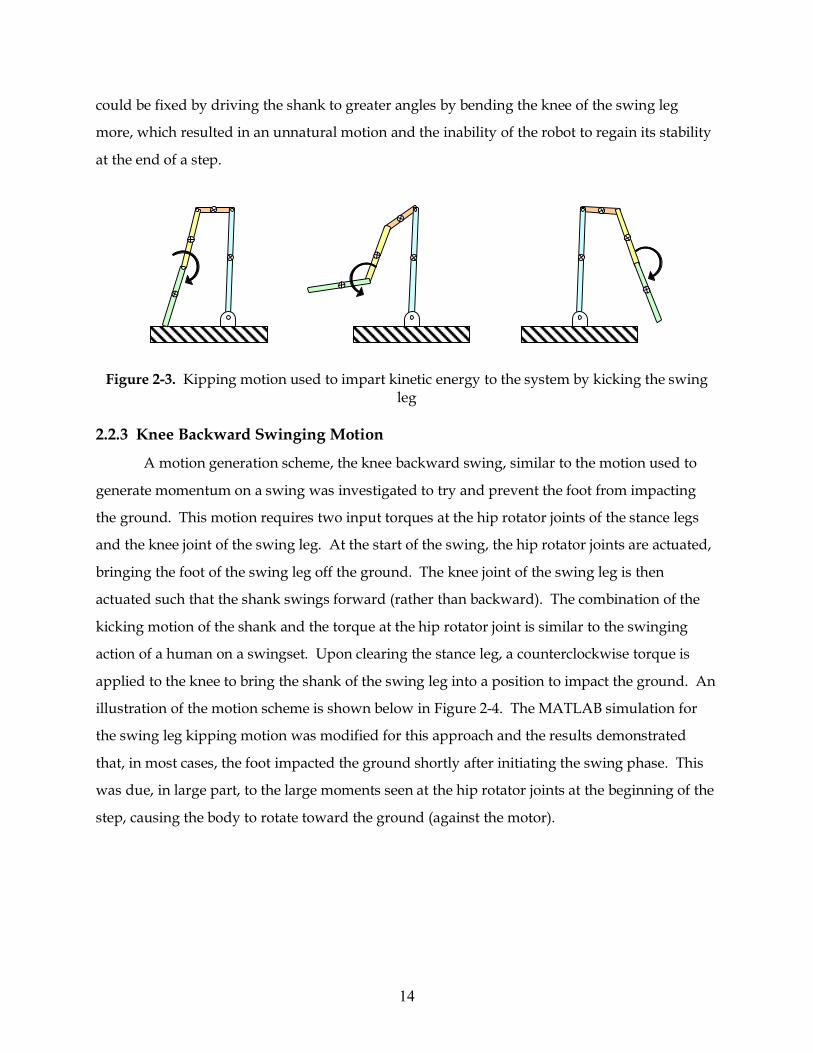
illustration of the motion scheme is shown below in Figure 2-4. The MATLAB simulation for
the swing leg kipping motion was modified for this approach and the results demonstrated
that, in most cases, the foot impacted the ground shortly after initiating the swing phase. This
was due, in large part, to the large moments seen at the hip rotator joints at the beginning of the
step, causing the body to rotate toward the ground (against the motor).
15
Figure 2-4. Knee backward motion scheme to prevent the foot from impacting the ground as it passes the stance leg
2.2.4 A Piecewise Active and Passive Approach
After having marginal success with the different motion generation approaches, another
motion scheme demonstrated that the STriDER could take a step successfully. The method
involved breaking down the swinging motion into several phases where joints alternate
between being active and passive depending on the desired motion. This method of motion
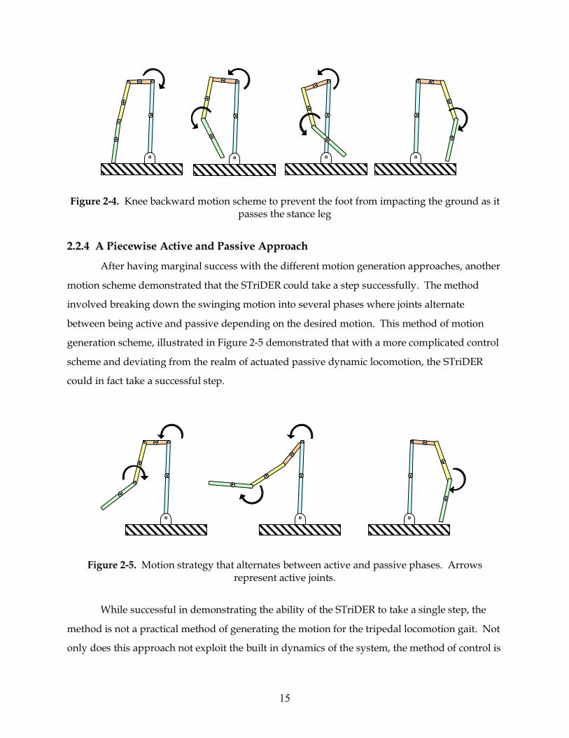
generation scheme, illustrated in Figure 2-5 demonstrated that with a more complicated control
scheme and deviating from the realm of actuated passive dynamic locomotion, the STriDER
could in fact take a successful step.
Figure 2-5. Motion strategy that alternates between active and passive phases. Arrows
represent active joints.
While successful in demonstrating the ability of the STriDER to take a single step, the
method is not a practical method of generating the motion for the tripedal locomotion gait. Not
only does this approach not exploit the built in dynamics of the system, the method of control is

16
not general enough for implementation in non-ideal (e.g. unstructured or rough) environments.
In addition, as the design parameters are changed, so do the torques and the timing of the
application of those torques necessary to drive the links though a desired motion. Therefore,
the torques become variables when trying to optimize a single step, further adding to the
complication of implementing the controller scheme.
2.2.5 Self-Excited Actuation
Inspired by the work of Ono et al. [22], a successful approach was found using the
concept of self-excited actuation. Self-excited actuation is based on self-excited vibration, a
phenomenon commonly referred to as flutter, which results when a stable system is excited at
one of its natural modes and driven to an unstable state. The inverted pendulum model of the
swing leg has two natural modes, one where the links move in phase with one another and a
second where the two move out of phase. The desired motion is for the thigh to swing forward
as the shank swings backward, so the second mode generated the necessary motion. An
illustration of Ono’s self-excited model is presented in Figure 2-6.
Figure 2-6. Self-excited model developed by Ono
Mathematically, self-excitation occurs when the stiffness matrix of a system
becomes asymmetric. By generating a torque at the hip with negative feedback to the shank
angle (measured from the vertical rather than relative to the previous link), the stiffness matrix
becomes asymmetric and the motion of the shank is delayed approximately 90 degrees from the
thigh motion. The torque at the hip is represented by equation 1.
T = −kθ3 (1)
θ3
T
17
The value of k can be determined by linearly approximated the equations of motion of
the system and determining for what values of k and what frequency will the eigenvalues of the
system go unstable. Although mathematically possible to calculate, the values for friction were
unknown and according to Ono, can greatly affect the values of k. Therefore, a trial and error
method was employed to determine the value of k. A wide range of k values was tried to
determine if the torque at the hip rotator joints were sufficient to generate the desired motion.
The larger the value of k was, the more likely the motor torques were to saturate. A k value of 5
Nm/rad produced the desired motion and prevented the motor torques from instantly
saturating upon initiating a step.
The self-excited method of control was used in the optimization for its simplicity and
robustness of the controller to create feasible gaits over a wide range of link parameters and
controller gains. Although Ono’s model was a three link bipedal walker it is still applicable for
use in the planer model of the four-link STriDER robot by altering the starting configuration of
the robot such that the pelvis and thigh of the swing leg were collinear, effectively creating a
three-link robot. The relative angle between these two links was then maintained by controlling
the hip flexure joint of the swing leg with a PD controller until the swing foot impacted the
ground. Once back in a stable tripod position again after taking a step, the joints could be then
actuated to position the links to reconfigure the body to prepare for the next step. An
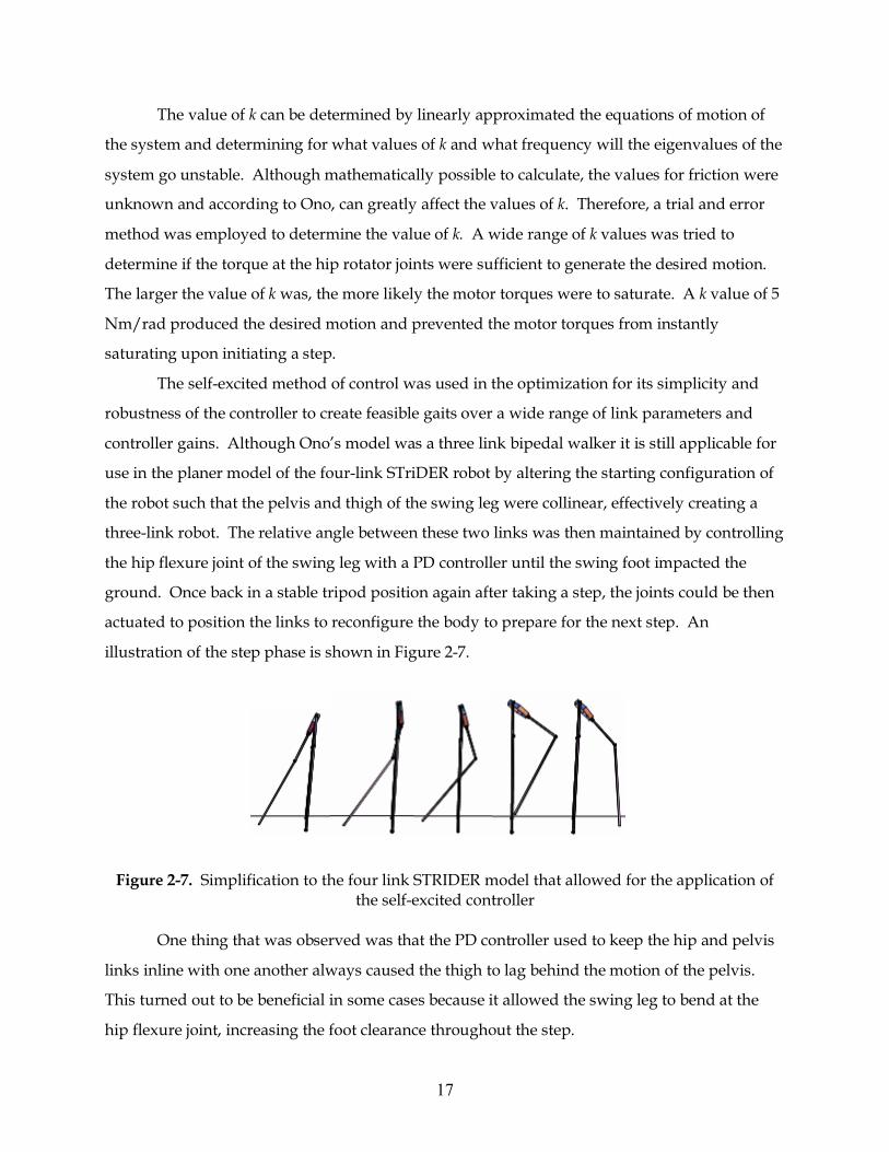
illustration of the step phase is shown in Figure 2-7.
Figure 2-7. Simplification to the four link STRIDER model that allowed for the application of
the self-excited controller
One thing that was observed was that the PD controller used to keep the hip and pelvis
links inline with one another always caused the thigh to lag behind the motion of the pelvis.
This turned out to be beneficial in some cases because it allowed the swing leg to bend at the
hip flexure joint, increasing the foot clearance throughout the step.
18
2.3 Parametric Study and Optimization Based on the Self-Excited Control Model A goal of the research was to gain some insight into how the design parameters, such as
link lengths and mass distributions, affected the motion of the robot and how the parameters
could be changed to create an optimal single step. In order to optimize the full model in Figure
2-1, as many as twelve parameters could be optimized. The mass, link length, moment of
inertia, and mass distribution (the location of center of mass) of links 2 through 4 could be
changed to get the desired motion. The properties for link 1, the stance legs, are automatically
determined by the properties of the thigh and shank links. To reduce the number of parameters,
simplifications were made to the model. First, the mass and the location of the center of mass of
the hip assembly (the body, hip and pelvis together treated as a single link) was assumed to be
constant, determined by the design of the machine. Second, due to the susceptibility of the hip
flexure joint motor to reach its torque saturation point, it was decided to keep the mass of the
thigh at a minimum. The location of the center of mass of this link was therefore kept constant
because additional mass would not be added to affect its location. The minimum mass and the
location of the center of mass were determined by the minimum weight of the components
needed to construct and drive the joints. Third, for the shank, the total mass of the link was
kept constant but its magnitude was greater than that of the thigh. Increasing the mass of the
shank allowed for greater flexibility in determining the location of the center of mass. Finally,
to further reduce the number of parameters to be optimized, the moment of inertia of the links
were assumed to be constant. The validity of these assumptions will be discussed in the
following chapter. These assumptions reduced the number of parameters to be optimized to
three (the length of the thigh and shank, and the location of center of mass of the shank).
The locomotion method of the STriDER is not one that can be characterized as having a
stable limit cycle since its gait strategy is to take a step, regain its stability, position itself for the
next step, and then initiate the next one. The constraint of having a stable limit cycle is therefore
not considered for the optimization. To develop the cost function to quantify how “good” a
step is, different criteria were added based on two premises: (1) will the resulting motion result
in damage to the robot and (2) will the resulting motion make it difficult or impossible to take
the next step. Five penalties were created to quantify the resulting motion of the step. First, the
19
horizontal and vertical velocities of the foot are evaluated. In an ideal case, the horizontal and
vertical velocities of the foot would be zero at the end of the step. A high horizontal velocity
could potentially lead to the foot slipping or skidding when it impacts the ground or loss of
energy due to the friction if the foot drags. A high vertical velocity could cause damage to the
links and joints due to the high impact with the ground at the foot. Next, the ratio between the
stride width for a single step to the overall height of the robot is evaluated. If this ratio is too
small, the robot will be unstable upon completion of a step. If the ratio is too large, the torque
produced by the motors may be insufficient to allow the robot to recover from its step. Another
criterion was that the height of the robot’s center of gravity at the beginning of the step should
be equal to the center of gravity at the end of the step. The reasoning behind this is that if the
center of gravity is lower at the end of the swing, insufficient energy was put into the system
and additional energy would have to put into the system to get the robot into a position to take
the next step. Conversely, if the center of gravity is higher than the beginning of the step, too
much energy was put into the system. Finally, the difference between the actual step length
and ideal step length was evaluated. For taking a straight step over a level surface, the three
feet of the STriDER make up an equilateral triangle. Any deviation from the ideal might lead to
a configuration at the end of the step that would make it difficult for the robot to reconfigure for
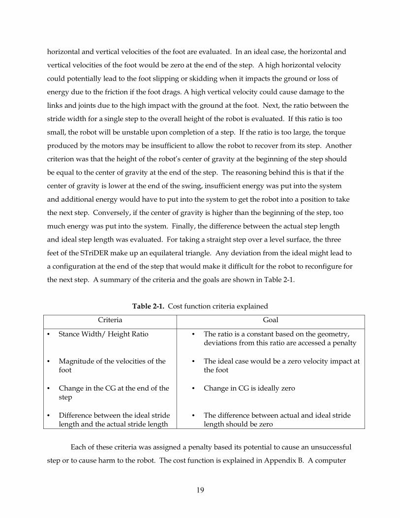
the next step. A summary of the criteria and the goals are shown in Table 2-1.
Table 2-1. Cost function criteria explained
Criteria Goal
• Stance Width/ Height Ratio
• Magnitude of the velocities of the
foot • Change in the CG at the end of the
step • Difference between the ideal stride
length and the actual stride length
• The ratio is a constant based on the geometry, deviations from this ratio are accessed a penalty
• The ideal case would be a zero velocity impact at
the foot • Change in CG is ideally zero
• The difference between actual and ideal stride length should be zero
Each of these criteria was assigned a penalty based its potential to cause an unsuccessful
step or to cause harm to the robot. The cost function is explained in Appendix B. A computer

20
program was developed to calculate a cost function with all combinations of design parameters
within the desired design space. The limits of the design space were set by the physical
limitations or applications of the robot. The lower limits of the link lengths were defined by the
needs of the reconnaissance work the robot would perform. In order to see over small
obstacles, the robot would need to be at least 1.0 meters tall. From previous work with the Port
Escap motors that would be used on the STriDER, a practical limitation on the total height of
the robot was approximately 2.5 meters based on the torque limits of the motor. The method
used in the optimization was crude, but the underlying principals are justified; the worse a
design was, the higher the design’s associated cost. A flow chart demonstrating the
optimization logic is presented in Figure 2-8.
Figure 2-8. Flowchart demonstrating how the design parameters were optimized for the
STriDER
2.4 Results and Discussions The optimization program yielded a set of parameters that produced a feasible gait for
the STriDER. The PD controller did a sufficient job in maintaining the joint angle between the
pelvis and thigh of the swing leg. Phase lag was still present but was beneficial in allowing the
leg to bend more, increasing foot clearance as the swing leg passed between the two stance legs.
With the optimized parameter values shown in Table 2-2 (refer to Figure 2-1 for link numbers),
the simulation showed that the STriDER can achieve a stride length of 0.539m and a maximum
walking speed of 0.735 m/s. The resulting 2D motion can be seen in Figure 2-9.
Initial guess for design parameters
ODE23 EOMs
Generate mass and force matrices
Application of motor controller
Cost function, Lowest Cost?
Increment values of design parameters
Optimal Values
No Yes
21
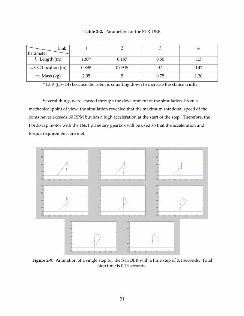
Table 2-2. Parameters for the STRIDER
1 2 3 4
l1, Length (m) 1.87* 0.187 0.50 1.3
ci, CG Location (m) 0.898 0.0935 0.1 0.42
mi, Mass (kg) 2.05 5 0.75 1.30
* L1 ≠ (L3+L4) because the robot is squatting down to increase the stance width
Several things were learned through the development of the simulation. From a
mechanical point of view, the simulation revealed that the maximum rotational speed of the
joints never exceeds 60 RPM but has a high acceleration at the start of the step. Therefore, the
PortEscap motor with the 166:1 planetary gearbox will be used so that the acceleration and
torque requirements are met.
Figure 2-9. Animation of a single step for the STriDER with a time step of 0.1 seconds. Total
step time is 0.73 seconds.
Parameter Linki
22
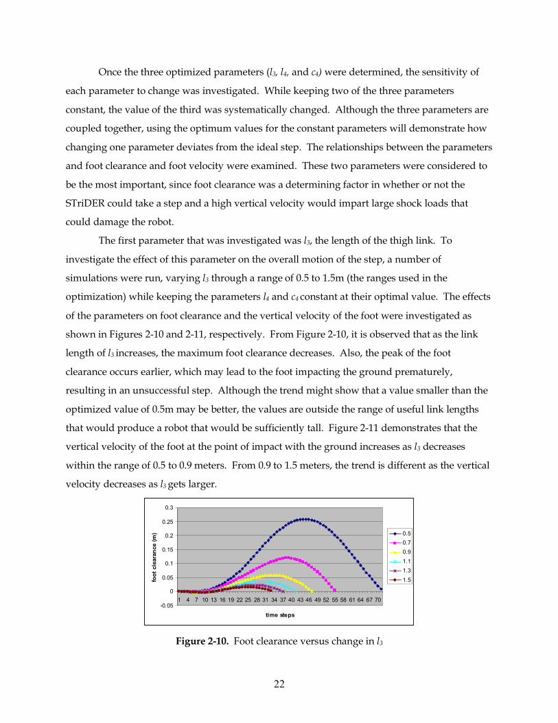
Once the three optimized parameters (l3, l4, and c4) were determined, the sensitivity of
each parameter to change was investigated. While keeping two of the three parameters
constant, the value of the third was systematically changed. Although the three parameters are
coupled together, using the optimum values for the constant parameters will demonstrate how
changing one parameter deviates from the ideal step. The relationships between the parameters
and foot clearance and foot velocity were examined. These two parameters were considered to
be the most important, since foot clearance was a determining factor in whether or not the
STriDER could take a step and a high vertical velocity would impart large shock loads that
could damage the robot.
The first parameter that was investigated was l3, the length of the thigh link. To
investigate the effect of this parameter on the overall motion of the step, a number of
simulations were run, varying l3 through a range of 0.5 to 1.5m (the ranges used in the
optimization) while keeping the parameters l4 and c4 constant at their optimal value. The effects
of the parameters on foot clearance and the vertical velocity of the foot were investigated as
shown in Figures 2-10 and 2-11, respectively. From Figure 2-10, it is observed that as the link
length of l3 increases, the maximum foot clearance decreases. Also, the peak of the foot
clearance occurs earlier, which may lead to the foot impacting the ground prematurely,
resulting in an unsuccessful step. Although the trend might show that a value smaller than the
optimized value of 0.5m may be better, the values are outside the range of useful link lengths
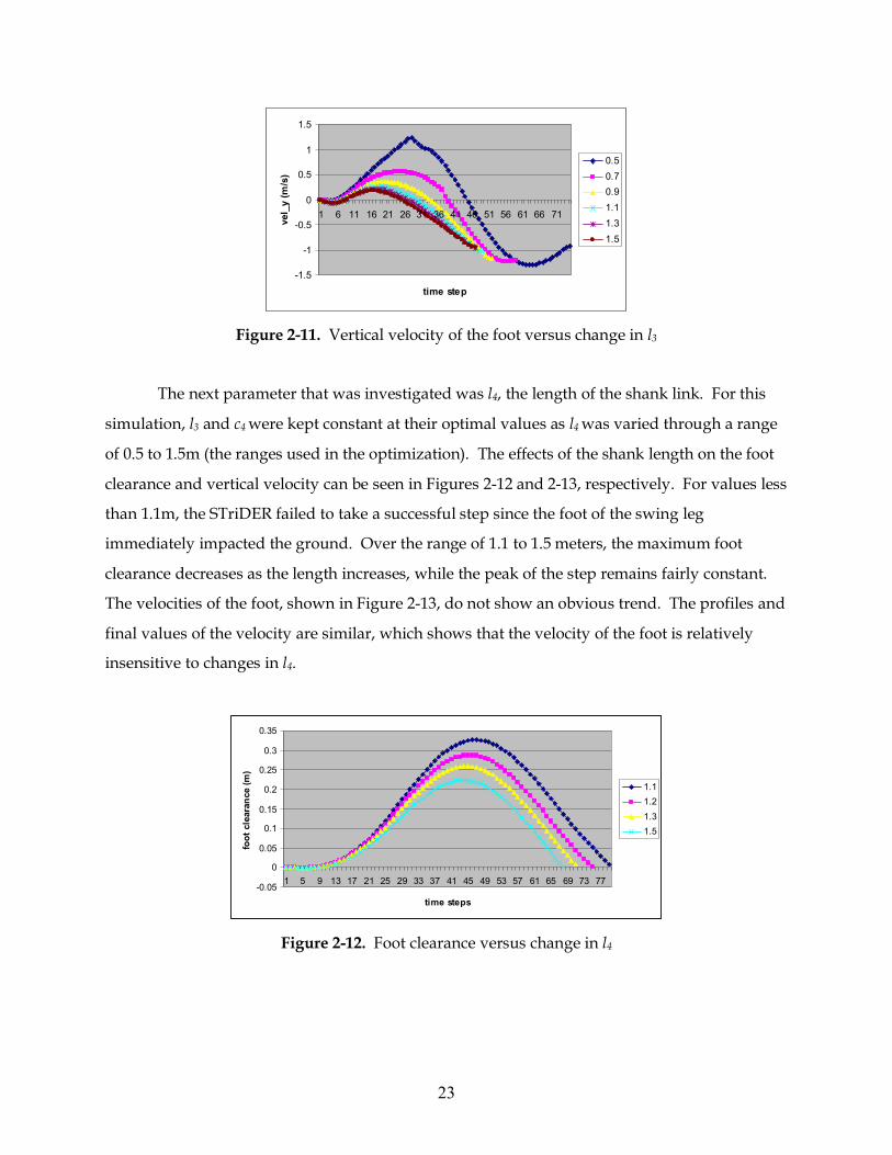
that would produce a robot that would be sufficiently tall. Figure 2-11 demonstrates that the
vertical velocity of the foot at the point of impact with the ground increases as l3 decreases
within the range of 0.5 to 0.9 meters. From 0.9 to 1.5 meters, the trend is different as the vertical
velocity decreases as l3 gets larger.
-0.05
0
0.05
0.1
0.15
0.2
0.25
0.3
1 4 7 10 13 16 19 22 25 28 31 34 37 40 43 46 49 52 55 58 61 64 67 70
time steps
foot
cle
aran
ce (m
) 0.50.70.91.11.31.5
Figure 2-10. Foot clearance versus change in l3
23
-1.5
-1
-0.5
0
0.5
1
1.5
1 6 11 16 21 26 31 36 41 46 51 56 61 66 71
time stepve
l_y
(m/s
)
0.50.70.91.11.31.5
Figure 2-11. Vertical velocity of the foot versus change in l3
The next parameter that was investigated was l4, the length of the shank link. For this
simulation, l3 and c4 were kept constant at their optimal values as l4 was varied through a range
of 0.5 to 1.5m (the ranges used in the optimization). The effects of the shank length on the foot
clearance and vertical velocity can be seen in Figures 2-12 and 2-13, respectively. For values less
than 1.1m, the STriDER failed to take a successful step since the foot of the swing leg
immediately impacted the ground. Over the range of 1.1 to 1.5 meters, the maximum foot
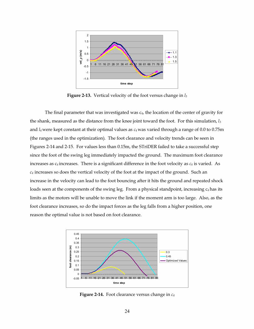
clearance decreases as the length increases, while the peak of the step remains fairly constant.
The velocities of the foot, shown in Figure 2-13, do not show an obvious trend. The profiles and
final values of the velocity are similar, which shows that the velocity of the foot is relatively
insensitive to changes in l4.
-0.05
0
0.05
0.1
0.15
0.2
0.25
0.3
0.35
1 5 9 13 17 21 25 29 33 37 41 45 49 53 57 61 65 69 73 77
time steps
foot
cle
aran
ce (m
)
1.11.21.31.5
Figure 2-12. Foot clearance versus change in l4
24
-1.5
-1
-0.5
0
0.5
1
1.5
2
1 6 11 16 21 26 31 36 41 46 51 56 61 66 71 76 81
time stepve
l_y
(m/s
)
1.11.31.5
Figure 2-13. Vertical velocity of the foot versus change in l3
The final parameter that was investigated was c4, the location of the center of gravity for
the shank, measured as the distance from the knee joint toward the foot. For this simulation, l3
and l4 were kept constant at their optimal values as c4 was varied through a range of 0.0 to 0.75m
(the ranges used in the optimization). The foot clearance and velocity trends can be seen in
Figures 2-14 and 2-15. For values less than 0.15m, the STriDER failed to take a successful step
since the foot of the swing leg immediately impacted the ground. The maximum foot clearance
increases as c4 increases. There is a significant difference in the foot velocity as c4 is varied. As
c4 increases so does the vertical velocity of the foot at the impact of the ground. Such an
increase in the velocity can lead to the foot bouncing after it hits the ground and repeated shock
loads seen at the components of the swing leg. From a physical standpoint, increasing c4 has its
limits as the motors will be unable to move the link if the moment arm is too large. Also, as the
foot clearance increases, so do the impact forces as the leg falls from a higher position, one
reason the optimal value is not based on foot clearance.
-0.05
0
0.05
0.1
0.15
0.2
0.25
0.3
0.35
0.4
0.45
1 6 11 16 21 26 31 36 41 46 51 56 61 66 71 76 81 86
time step
foot
cle
aran
ce (m
)
0.30.45Optimized Values
Figure 2-14. Foot clearance versus change in c4

25
-2
-1.5
-1
-0.5
0
0.5
1
1.5
2
1 6 11 16 21 26 31 36 41 46 51 56 61 66 71 76 81 86
time stepve
l_y
(m/s
)
0.150.30.45
Figure 2-15. Vertical velocity of the foot versus change in c4
c4
26
Chapter 3 Design of the Tripedal Locomotion Robot The original model that was used to develop the concept of the STriDER was a simple
3D Studio Max model that allowed the user to pull the links through their prescribed motions.
This generic model was used to define the ways in which the joints moved and dictated the
number of degrees of freedom for each joint. One of the tasks for this research was to develop
the first working prototype of the STriDER for proof of concept and validation of the
optimization process. The design will be continuously evolving as the research objectives
change in future projects. The next few sections outline the design of the knee and hip joints, as
well as discuss the implementation of the motor controllers in the robot prototype.
3.1 Design Overview of the System
Designs of bipedal walkers based on passive dynamic locomotion are similar. Each
design is driven by the same constraints, that of establishing a stable limit cycle, which requires
a stopper at the knee to create a plastic collision (after the collision the shank and thigh act as
one joint) and being able to transfer momentum from the swing leg to the stance leg through the
impact of the swing foot with the ground. The design of the STriDER is driven by a few of the
principles of passive dynamic locomotion, such as tuning the design parameters in order to
manipulate the built in dynamics of the system. However, because the gait of the STriDER is
different than that of other walking robots, the criteria of establishing stable gait cycles and
modeling of the transfer of momentum between the stance and swing legs are no longer
applicable. Unlike passive dynamic walkers, whose knees are prevented from hyperextending,
the additional rotational freedom at the knee is necessary for some applications (e.g., folding the
legs of the STriDER so that the robot is compact and can be deployed from a ground or air
platform). The design constraints are therefore not dictated by the principles of passive
dynamic walkers but rather by the use of the robot in real world applications.
27
The height of the STriDER was dictated by the duties it could potentially perform. As a
reconnaissance robot, the STriDER would need to be tall enough to see over obstacles, an
advantage over smaller, wheeled and legged robots. The leg links could therefore potentially
be long, requiring tight tolerances on joints. Several millimeters of motion at a joint such as the
knee, caused by a loose bearing for example, could lead to magnitudes greater motion at the
foot if the shank link was sufficiently long. Careful consideration was given to the quality of
bearings, bearing spacing, and tolerances on machined parts in the joint. Also, the joints of the
STriDER may be subject to large impulsive loads, generated when the foot impacts the ground
or other obstacles. Therefore, the design of the joints was required to be robust. A compromise
between robustness and weight was considered as forces in the joints rise proportionally to the
mass. Therefore, simply overdesigning the joints would be insufficient. Finally, to aide the
STriDER in navigating rough or cluttered terrain, the motors, wires, and any additional
hardware should be protected from unexpected obstructions.
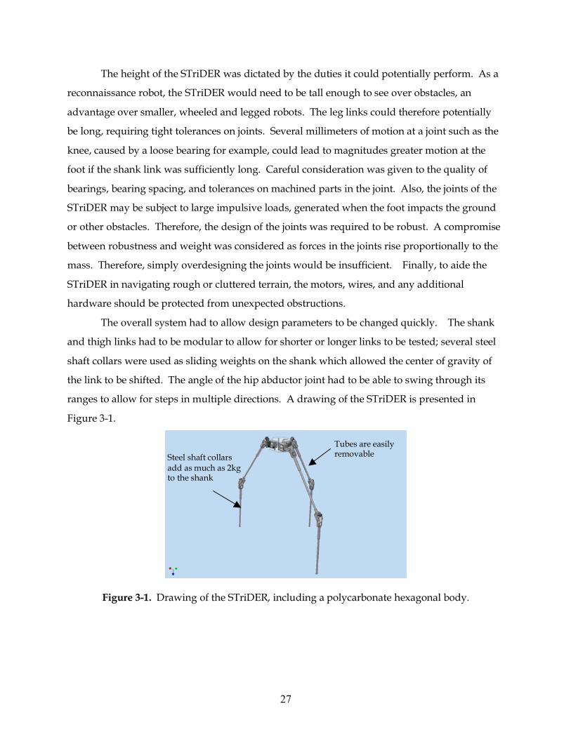
The overall system had to allow design parameters to be changed quickly. The shank
and thigh links had to be modular to allow for shorter or longer links to be tested; several steel
shaft collars were used as sliding weights on the shank which allowed the center of gravity of
the link to be shifted. The angle of the hip abductor joint had to be able to swing through its
ranges to allow for steps in multiple directions. A drawing of the STriDER is presented in
Figure 3-1.
Figure 3-1. Drawing of the STriDER, including a polycarbonate hexagonal body.
Tubes are easily removable Steel shaft collars
add as much as 2kg to the shank
28
3.2 Design of the Knee Joint
As the first design constraints were being investigated, the question of using bearings or
bushings arose. While each has its own strengths and weaknesses, the choice between the two
was decided upon by their application in the STriDER. Both bearings and bushings can be
purchased with high tolerances, reducing the amount of lateral play in any of the output shafts.
However, the tight tolerances on bushings can be negated due to wear between the shaft and
the bushing. Typically, the advantage of bushings is their size, cost, weight, and high shock
tolerance. Bearings, on the other hand, can provide smooth operation at higher speeds,
generate less wear on components, and typically have lower coefficients of friction. A solution
was found in SPB-USA, a company specializing in miniature high-precision bearings. Now, the
operational benefits of bearings, such as reduced wear and smooth operation, could be
combined with the size and weight benefits of bushings. Also, since the STriDER is based on
passive dynamic locomotion, the greatest constraint on the design is that the motion of the links
be as frictionless as possible.
One goal in designing the knee joint was to create a joint that would allow the motor to
be in line with the leg link. This required that the power transmission between the motor
output shaft and the joint axis of rotation be at 90 degrees to one another. Driving the motor in
such a way would allow the motor to be encapsulated by the leg link, thereby reducing the
volume of the joint and reducing the risk of entanglement with the other legs or the
surrounding obstacles in the environment as the STriDER takes a step. There are two common
choices when considering perpendicular drives: helical gears and their variants or bevel gears.
While both are suitable for this application, bevel gears were chosen based on their higher
efficiency and lower weight. Using the equations for gear selectors on Boston Gear’s website
(http://www.bostongear.com), it was determined that Boston Gear’s plastic bevel gears would
be sufficient for short term testing. For increased reliability over long term operation, metal
gears would be recommended.
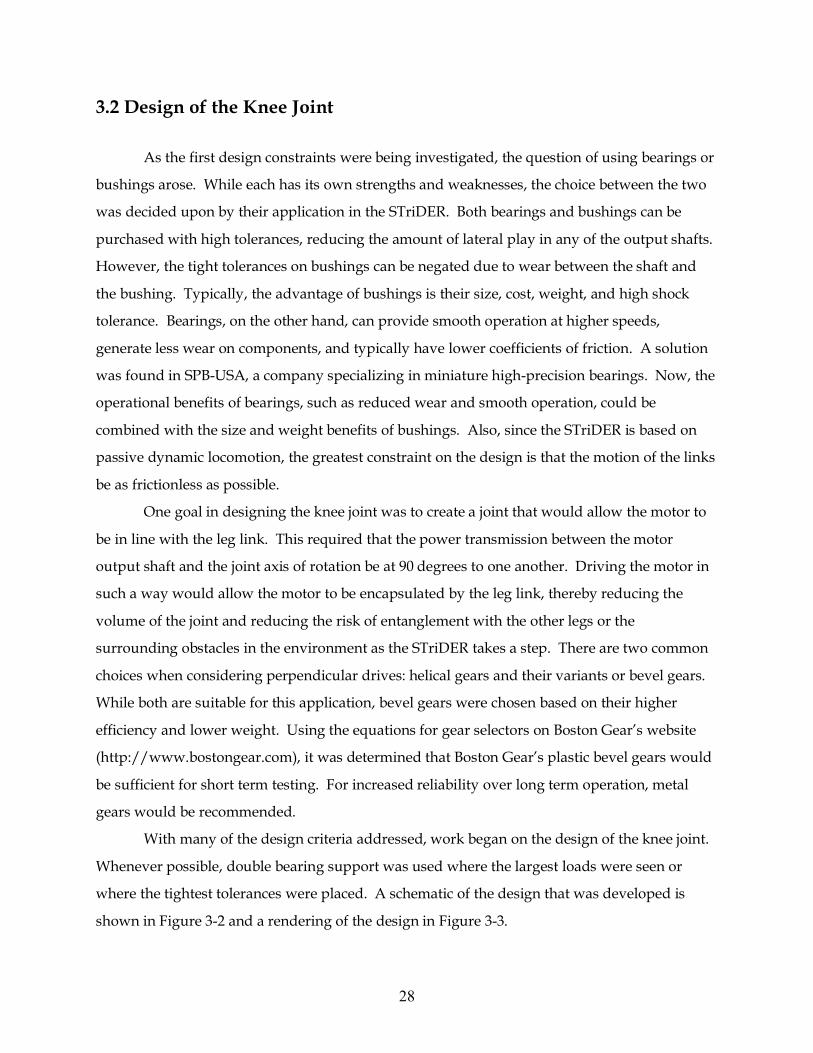
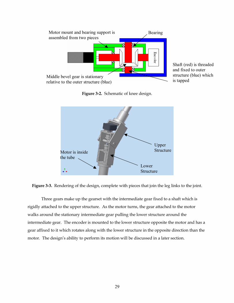
With many of the design criteria addressed, work began on the design of the knee joint.
Whenever possible, double bearing support was used where the largest loads were seen or
where the tightest tolerances were placed. A schematic of the design that was developed is
shown in Figure 3-2 and a rendering of the design in Figure 3-3.
29
Figure 3-2. Schematic of knee design.
Figure 3-3. Rendering of the design, complete with pieces that join the leg links to the joint.
Three gears make up the gearset with the intermediate gear fixed to a shaft which is
rigidly attached to the upper structure. As the motor turns, the gear attached to the motor
walks around the stationary intermediate gear pulling the lower structure around the
intermediate gear. The encoder is mounted to the lower structure opposite the motor and has a
gear affixed to it which rotates along with the lower structure in the opposite direction than the
motor. The design’s ability to perform its motion will be discussed in a later section.
Motor is inside the tube
Lower Structure
Upper Structure
Shaft (red) is threaded and fixed to outer structure (blue) which is tapped
Middle bevel gear is stationary relative to the outer structure (blue)
Bearing Motor mount and bearing support is assembled from two pieces
30
3.3 Design of the Three Hip Joints
One advantage of the STriDER over walking robots based on passive dynamic walking
is the ability to change its direction. In order to accomplish this, the motions of the hip joints are
unique to the STriDER and design inspirations cannot be found in other walking machines.
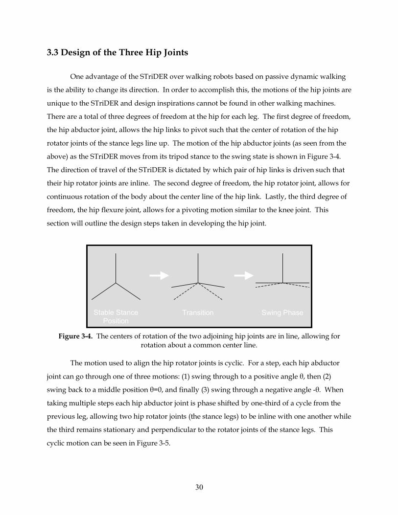
There are a total of three degrees of freedom at the hip for each leg. The first degree of freedom,
the hip abductor joint, allows the hip links to pivot such that the center of rotation of the hip
rotator joints of the stance legs line up. The motion of the hip abductor joints (as seen from the
above) as the STriDER moves from its tripod stance to the swing state is shown in Figure 3-4.
The direction of travel of the STriDER is dictated by which pair of hip links is driven such that
their hip rotator joints are inline. The second degree of freedom, the hip rotator joint, allows for
continuous rotation of the body about the center line of the hip link. Lastly, the third degree of
freedom, the hip flexure joint, allows for a pivoting motion similar to the knee joint. This
section will outline the design steps taken in developing the hip joint.
Figure 3-4. The centers of rotation of the two adjoining hip joints are in line, allowing for
rotation about a common center line.
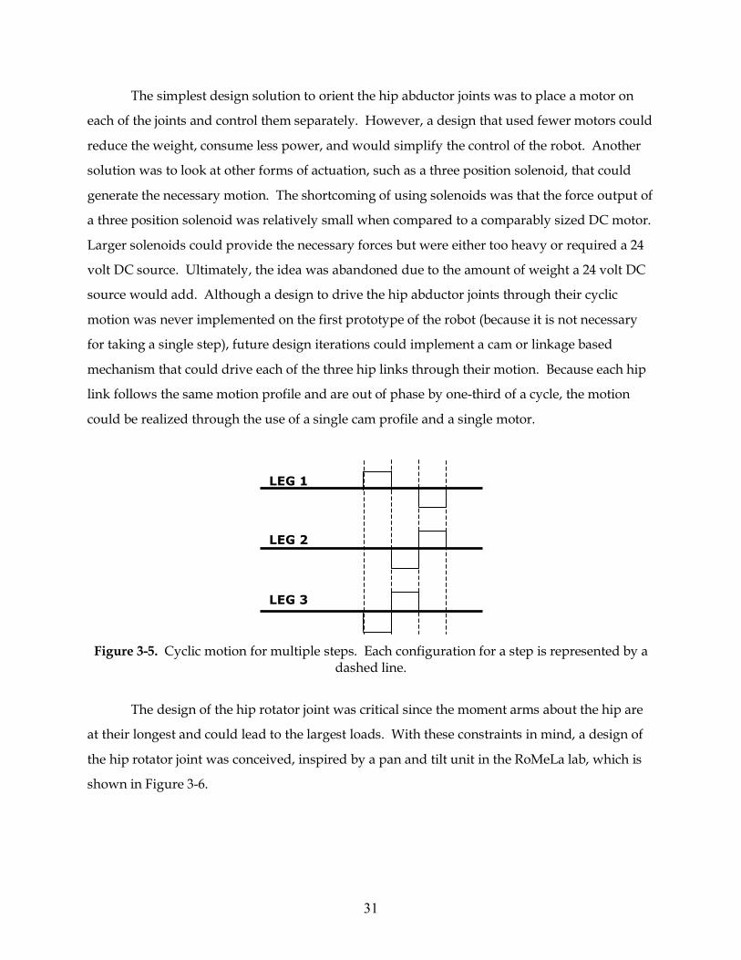
The motion used to align the hip rotator joints is cyclic. For a step, each hip abductor
joint can go through one of three motions: (1) swing through to a positive angle θ, then (2)
swing back to a middle position θ=0, and finally (3) swing through a negative angle -θ. When
taking multiple steps each hip abductor joint is phase shifted by one-third of a cycle from the
previous leg, allowing two hip rotator joints (the stance legs) to be inline with one another while
the third remains stationary and perpendicular to the rotator joints of the stance legs. This
cyclic motion can be seen in Figure 3-5.
Stable Stance Position
Transition Swing Phase
31
The simplest design solution to orient the hip abductor joints was to place a motor on
each of the joints and control them separately. However, a design that used fewer motors could
reduce the weight, consume less power, and would simplify the control of the robot. Another
solution was to look at other forms of actuation, such as a three position solenoid, that could
generate the necessary motion. The shortcoming of using solenoids was that the force output of
a three position solenoid was relatively small when compared to a comparably sized DC motor.
Larger solenoids could provide the necessary forces but were either too heavy or required a 24
volt DC source. Ultimately, the idea was abandoned due to the amount of weight a 24 volt DC
source would add. Although a design to drive the hip abductor joints through their cyclic
motion was never implemented on the first prototype of the robot (because it is not necessary
for taking a single step), future design iterations could implement a cam or linkage based
mechanism that could drive each of the three hip links through their motion. Because each hip
link follows the same motion profile and are out of phase by one-third of a cycle, the motion
could be realized through the use of a single cam profile and a single motor.
Figure 3-5. Cyclic motion for multiple steps. Each configuration for a step is represented by a
dashed line.
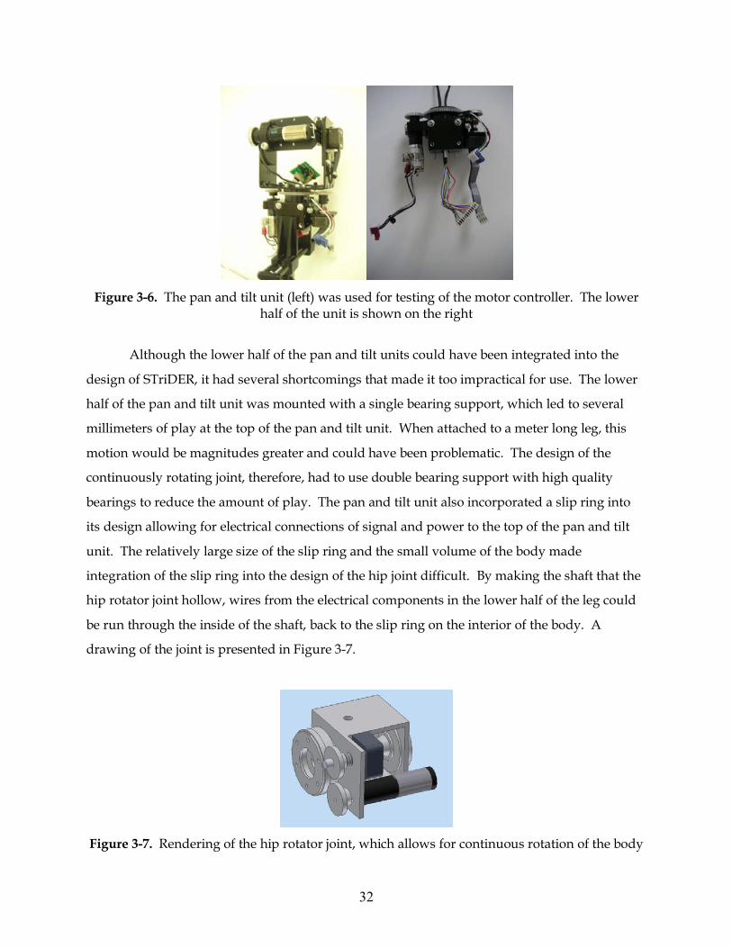
The design of the hip rotator joint was critical since the moment arms about the hip are
at their longest and could lead to the largest loads. With these constraints in mind, a design of
the hip rotator joint was conceived, inspired by a pan and tilt unit in the RoMeLa lab, which is
shown in Figure 3-6.
LEG 1
LEG 2
LEG 3
32
Figure 3-6. The pan and tilt unit (left) was used for testing of the motor controller. The lower
half of the unit is shown on the right
Although the lower half of the pan and tilt units could have been integrated into the
design of STriDER, it had several shortcomings that made it too impractical for use. The lower
half of the pan and tilt unit was mounted with a single bearing support, which led to several
millimeters of play at the top of the pan and tilt unit. When attached to a meter long leg, this
motion would be magnitudes greater and could have been problematic. The design of the
continuously rotating joint, therefore, had to use double bearing support with high quality
bearings to reduce the amount of play. The pan and tilt unit also incorporated a slip ring into
its design allowing for electrical connections of signal and power to the top of the pan and tilt
unit. The relatively large size of the slip ring and the small volume of the body made
integration of the slip ring into the design of the hip joint difficult. By making the shaft that the
hip rotator joint hollow, wires from the electrical components in the lower half of the leg could
be run through the inside of the shaft, back to the slip ring on the interior of the body. A
drawing of the joint is presented in Figure 3-7.
Figure 3-7. Rendering of the hip rotator joint, which allows for continuous rotation of the body
33
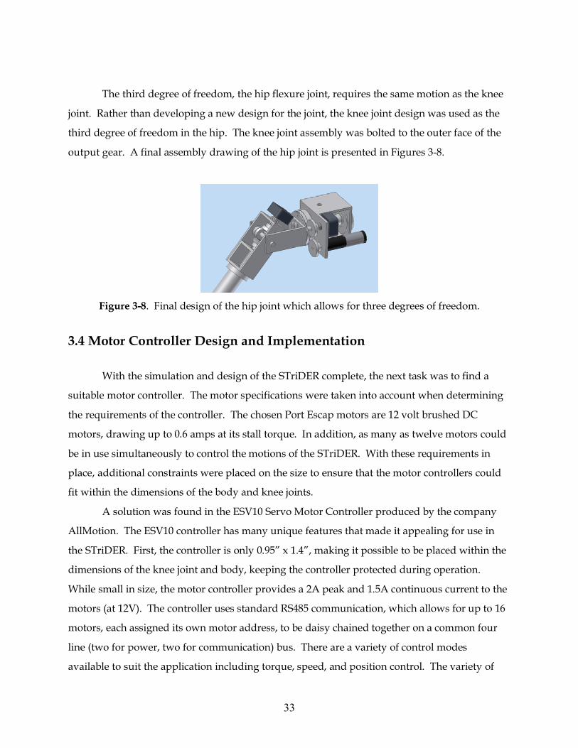
The third degree of freedom, the hip flexure joint, requires the same motion as the knee
joint. Rather than developing a new design for the joint, the knee joint design was used as the
third degree of freedom in the hip. The knee joint assembly was bolted to the outer face of the
output gear. A final assembly drawing of the hip joint is presented in Figures 3-8.
Figure 3-8. Final design of the hip joint which allows for three degrees of freedom.
3.4 Motor Controller Design and Implementation
With the simulation and design of the STriDER complete, the next task was to find a
suitable motor controller. The motor specifications were taken into account when determining
the requirements of the controller. The chosen Port Escap motors are 12 volt brushed DC
motors, drawing up to 0.6 amps at its stall torque. In addition, as many as twelve motors could
be in use simultaneously to control the motions of the STriDER. With these requirements in
place, additional constraints were placed on the size to ensure that the motor controllers could
fit within the dimensions of the body and knee joints.
A solution was found in the ESV10 Servo Motor Controller produced by the company
AllMotion. The ESV10 controller has many unique features that made it appealing for use in
the STriDER. First, the controller is only 0.95” x 1.4”, making it possible to be placed within the
dimensions of the knee joint and body, keeping the controller protected during operation.
While small in size, the motor controller provides a 2A peak and 1.5A continuous current to the
motors (at 12V). The controller uses standard RS485 communication, which allows for up to 16
motors, each assigned its own motor address, to be daisy chained together on a common four
line (two for power, two for communication) bus. There are a variety of control modes
available to suit the application including torque, speed, and position control. The variety of
34
control options is possible because of the integration of quadrature encoding feedback on the
chip. Lastly, the controller has an integrated I/O port that allows for additional electro-optical
and mechanical switches. A picture of the ESV10 Servo Motor Controller is shown in Figure 3-
9.
Figure 3-9. ESV10 Servo Motor Controller measures only 0.95” x 1.4”
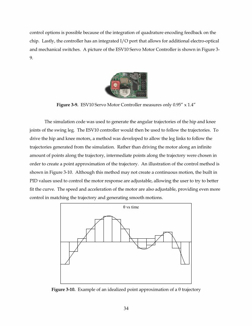
The simulation code was used to generate the angular trajectories of the hip and knee
joints of the swing leg. The ESV10 controller would then be used to follow the trajectories. To
drive the hip and knee motors, a method was developed to allow the leg links to follow the
trajectories generated from the simulation. Rather than driving the motor along an infinite
amount of points along the trajectory, intermediate points along the trajectory were chosen in
order to create a point approximation of the trajectory. An illustration of the control method is
shown in Figure 3-10. Although this method may not create a continuous motion, the built in
PID values used to control the motor response are adjustable, allowing the user to try to better
fit the curve. The speed and acceleration of the motor are also adjustable, providing even more
control in matching the trajectory and generating smooth motions.
Figure 3-10. Example of an idealized point approximation of a θ trajectory
θ vs time
35
The number of points used to approximate the curve will be investigated during testing
of the STriDER; the results of which will be discussed in the next chapter. The smoothness of
operation and ability of the controller to follow the trajectories generated by the MATLAB
simulation will also be investigated.
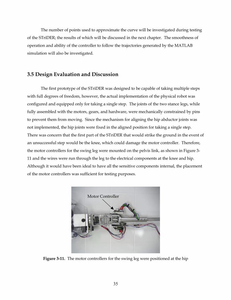
3.5 Design Evaluation and Discussion The first prototype of the STriDER was designed to be capable of taking multiple steps
with full degrees of freedom, however, the actual implementation of the physical robot was
configured and equipped only for taking a single step. The joints of the two stance legs, while
fully assembled with the motors, gears, and hardware, were mechanically constrained by pins
to prevent them from moving. Since the mechanism for aligning the hip abductor joints was
not implemented, the hip joints were fixed in the aligned position for taking a single step.
There was concern that the first part of the STriDER that would strike the ground in the event of
an unsuccessful step would be the knee, which could damage the motor controller. Therefore,
the motor controllers for the swing leg were mounted on the pelvis link, as shown in Figure 3-
11 and the wires were run through the leg to the electrical components at the knee and hip.
Although it would have been ideal to have all the sensitive components internal, the placement
of the motor controllers was sufficient for testing purposes.
Figure 3-11. The motor controllers for the swing leg were positioned at the hip
Motor Controller
36
During testing, the robustness of the design came into question. While able to function
and take a single step, the design of the STriDER had several design shortcomings that should
be addressed in future design revisions. Some problems were fundamental design flaws which
can only be fixed by design revisions, while others resulted from mistakes in the fabrication
process. To begin, the design of the knee joint, while elegant, compact and simple, could have
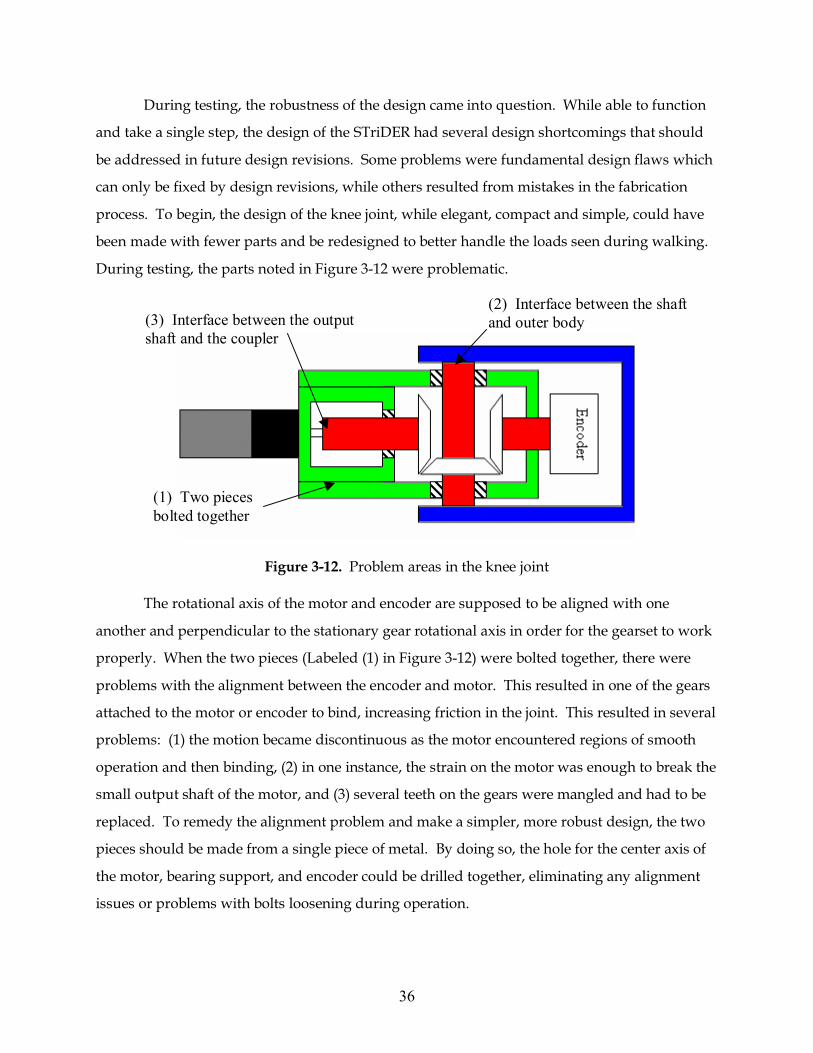
been made with fewer parts and be redesigned to better handle the loads seen during walking.
During testing, the parts noted in Figure 3-12 were problematic.
Figure 3-12. Problem areas in the knee joint
The rotational axis of the motor and encoder are supposed to be aligned with one
another and perpendicular to the stationary gear rotational axis in order for the gearset to work
properly. When the two pieces (Labeled (1) in Figure 3-12) were bolted together, there were
problems with the alignment between the encoder and motor. This resulted in one of the gears
attached to the motor or encoder to bind, increasing friction in the joint. This resulted in several
problems: (1) the motion became discontinuous as the motor encountered regions of smooth
operation and then binding, (2) in one instance, the strain on the motor was enough to break the
small output shaft of the motor, and (3) several teeth on the gears were mangled and had to be
replaced. To remedy the alignment problem and make a simpler, more robust design, the two
pieces should be made from a single piece of metal. By doing so, the hole for the center axis of
the motor, bearing support, and encoder could be drilled together, eliminating any alignment
issues or problems with bolts loosening during operation.
(1) Two pieces bolted together
(2) Interface between the shaft and outer body (3) Interface between the output
shaft and the coupler
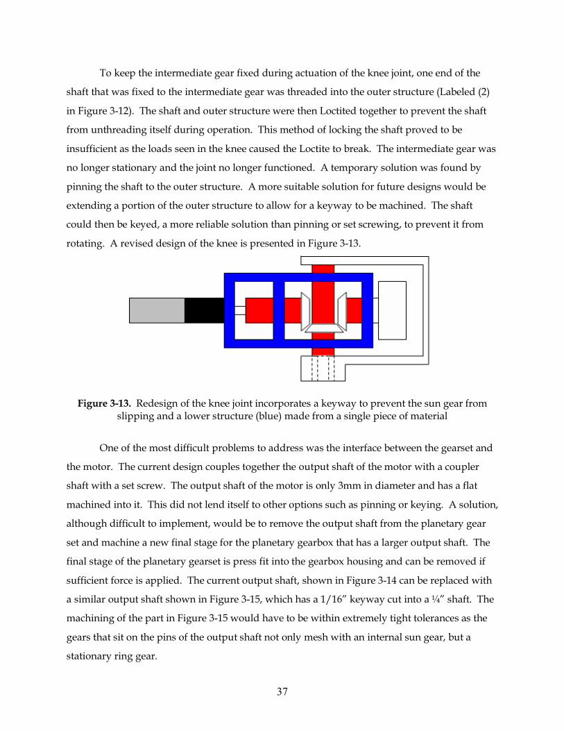
37
To keep the intermediate gear fixed during actuation of the knee joint, one end of the
shaft that was fixed to the intermediate gear was threaded into the outer structure (Labeled (2)
in Figure 3-12). The shaft and outer structure were then Loctited together to prevent the shaft
from unthreading itself during operation. This method of locking the shaft proved to be
insufficient as the loads seen in the knee caused the Loctite to break. The intermediate gear was
no longer stationary and the joint no longer functioned. A temporary solution was found by
pinning the shaft to the outer structure. A more suitable solution for future designs would be
extending a portion of the outer structure to allow for a keyway to be machined. The shaft
could then be keyed, a more reliable solution than pinning or set screwing, to prevent it from
rotating. A revised design of the knee is presented in Figure 3-13.
Figure 3-13. Redesign of the knee joint incorporates a keyway to prevent the sun gear from
slipping and a lower structure (blue) made from a single piece of material
One of the most difficult problems to address was the interface between the gearset and
the motor. The current design couples together the output shaft of the motor with a coupler
shaft with a set screw. The output shaft of the motor is only 3mm in diameter and has a flat
machined into it. This did not lend itself to other options such as pinning or keying. A solution,
although difficult to implement, would be to remove the output shaft from the planetary gear
set and machine a new final stage for the planetary gearbox that has a larger output shaft. The
final stage of the planetary gearset is press fit into the gearbox housing and can be removed if
sufficient force is applied. The current output shaft, shown in Figure 3-14 can be replaced with
a similar output shaft shown in Figure 3-15, which has a 1/16” keyway cut into a ¼” shaft. The
machining of the part in Figure 3-15 would have to be within extremely tight tolerances as the
gears that sit on the pins of the output shaft not only mesh with an internal sun gear, but a
stationary ring gear.
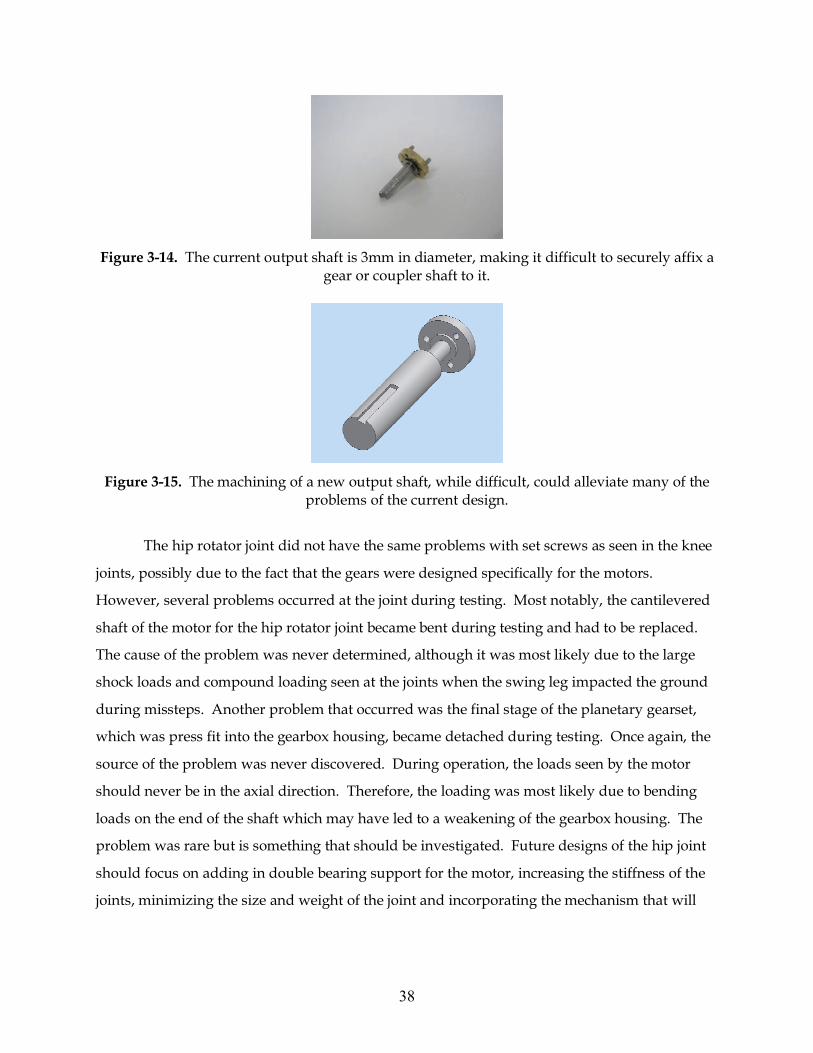
38
Figure 3-14. The current output shaft is 3mm in diameter, making it difficult to securely affix a
gear or coupler shaft to it.
Figure 3-15. The machining of a new output shaft, while difficult, could alleviate many of the
problems of the current design.
The hip rotator joint did not have the same problems with set screws as seen in the knee
joints, possibly due to the fact that the gears were designed specifically for the motors.
However, several problems occurred at the joint during testing. Most notably, the cantilevered
shaft of the motor for the hip rotator joint became bent during testing and had to be replaced.
The cause of the problem was never determined, although it was most likely due to the large
shock loads and compound loading seen at the joints when the swing leg impacted the ground
during missteps. Another problem that occurred was the final stage of the planetary gearset,
which was press fit into the gearbox housing, became detached during testing. Once again, the
source of the problem was never discovered. During operation, the loads seen by the motor
should never be in the axial direction. Therefore, the loading was most likely due to bending
loads on the end of the shaft which may have led to a weakening of the gearbox housing. The
problem was rare but is something that should be investigated. Future designs of the hip joint
should focus on adding in double bearing support for the motor, increasing the stiffness of the
joints, minimizing the size and weight of the joint and incorporating the mechanism that will
39
produce the cyclic motion of the hip link, required for changing the step direction. Stiff multi-
degree-of-freedom joints like the ones developed by Tesar [29] should be investigated.
Future designs might take advantage of the scalability of the STriDER and researchers
might consider designing larger robots. The loads seen at the joints of a 5 meter tall robot could
potentially be greater and a design such as the one in Figure 3-1 may be insufficient.
40
Chapter 4 Experimentation Experiments were run to test the effects of noise generated in the slip rings in the four-
wire RS485 bus, to test the ability of the motor controllers to accurately follow the trajectories
generated from the MATLAB simulation, and to validate the optimization code. This chapter
will present the setup and procedures for the experiments and discuss the findings.
4.1 Testing for Signal Noise Produced by the Slip Ring Although the scope of this research only covers a single step of the STriDER, future
research projects will look at multiple steps for path planning, obstacle avoidance, and three
dimensional dynamics. When taking multiple steps, the body is continuously rotating about
the hip rotator joints, requiring the use of slip rings to pass electrical signals down to the
electrical components in the leg (motor controllers, batteries, sensors, etc.). Tests needed to be
conducted to determine whether the noise generated in a slip ring would be significant enough
to cause errors in the signal sent to the motor controller. Typical noise values for the family of
Moog slip rings being investigated are 60mΩ at 6VDC and 50mA when running at 10RPM. To
determine the effects of noise through the slip ring of the STriDER, a pan and tilt unit was wired
to an AllMotion motor controller. A Moog AC6299 12-conductor slip ring was placed in-line
with the four-wire RS485 bus. A serial command was sent across the bus to the motor controller
and the frequency response of the signal was measured using an oscilloscope. The test was
then repeated with the slip ring rotating at a low speed (10-20 RPM) and high speeds (120
RPM). The slip ring was then removed and the test run again. The frequency responses of the
signals were then compared to determine whether the slip ring affected the signal.
The tests demonstrated that the Moog AC6299 slip rings do not produce significant
enough noise to disrupt the signal going to the motor controllers. Figures 4-1a and 4-1b show
the frequency response of the signal without the slip ring and with the slip ring at low RPMs.
The frequency response for the slip ring at high RPM produced little noise and produced a
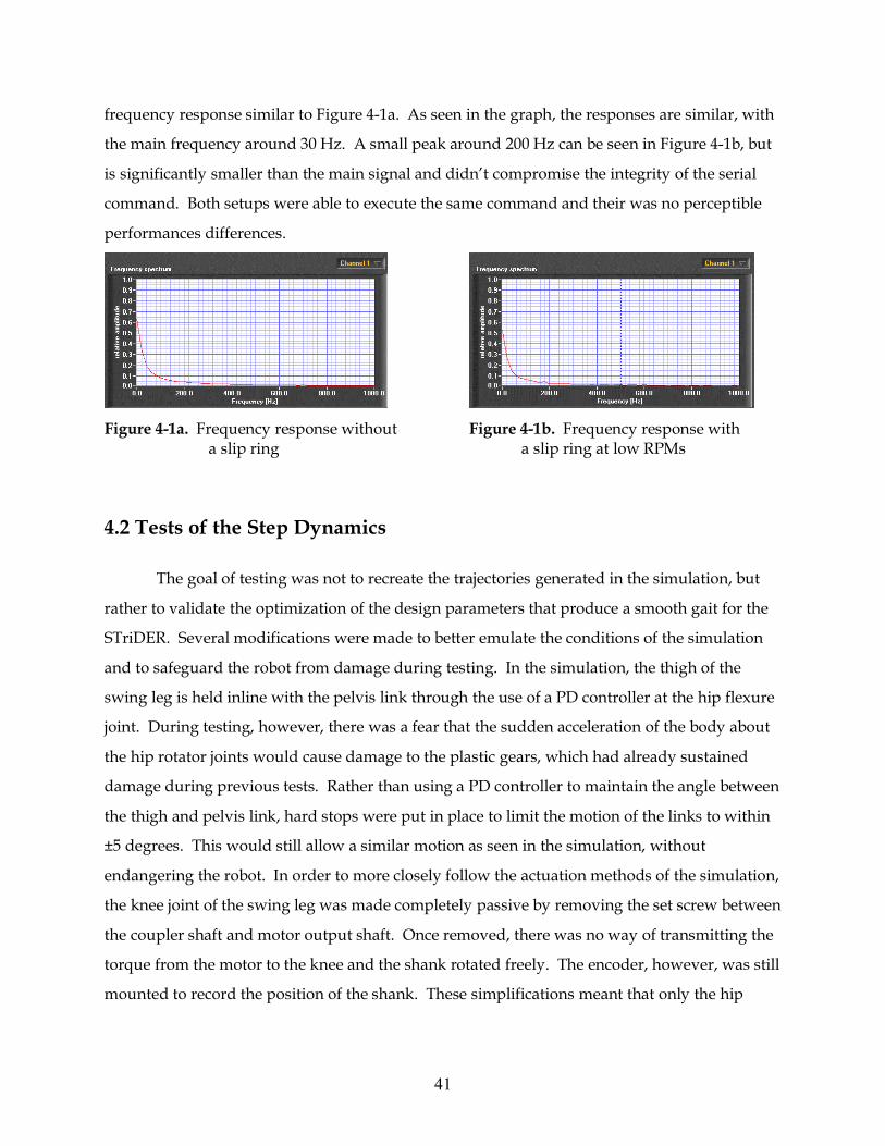
41
frequency response similar to Figure 4-1a. As seen in the graph, the responses are similar, with
the main frequency around 30 Hz. A small peak around 200 Hz can be seen in Figure 4-1b, but
is significantly smaller than the main signal and didn’t compromise the integrity of the serial
command. Both setups were able to execute the same command and their was no perceptible
performances differences.
Figure 4-1a. Frequency response without Figure 4-1b. Frequency response with a slip ring a slip ring at low RPMs
4.2 Tests of the Step Dynamics
The goal of testing was not to recreate the trajectories generated in the simulation, but
rather to validate the optimization of the design parameters that produce a smooth gait for the
STriDER. Several modifications were made to better emulate the conditions of the simulation
and to safeguard the robot from damage during testing. In the simulation, the thigh of the
swing leg is held inline with the pelvis link through the use of a PD controller at the hip flexure
joint. During testing, however, there was a fear that the sudden acceleration of the body about
the hip rotator joints would cause damage to the plastic gears, which had already sustained
damage during previous tests. Rather than using a PD controller to maintain the angle between
the thigh and pelvis link, hard stops were put in place to limit the motion of the links to within
±5 degrees. This would still allow a similar motion as seen in the simulation, without
endangering the robot. In order to more closely follow the actuation methods of the simulation,
the knee joint of the swing leg was made completely passive by removing the set screw between
the coupler shaft and motor output shaft. Once removed, there was no way of transmitting the
torque from the motor to the knee and the shank rotated freely. The encoder, however, was still
mounted to record the position of the shank. These simplifications meant that only the hip
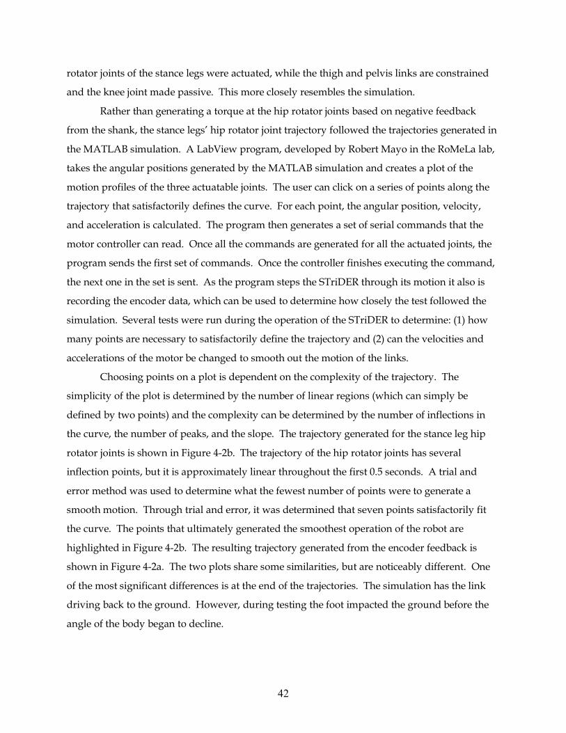
42
rotator joints of the stance legs were actuated, while the thigh and pelvis links are constrained
and the knee joint made passive. This more closely resembles the simulation.
Rather than generating a torque at the hip rotator joints based on negative feedback
from the shank, the stance legs’ hip rotator joint trajectory followed the trajectories generated in
the MATLAB simulation. A LabView program, developed by Robert Mayo in the RoMeLa lab,
takes the angular positions generated by the MATLAB simulation and creates a plot of the
motion profiles of the three actuatable joints. The user can click on a series of points along the
trajectory that satisfactorily defines the curve. For each point, the angular position, velocity,
and acceleration is calculated. The program then generates a set of serial commands that the
motor controller can read. Once all the commands are generated for all the actuated joints, the
program sends the first set of commands. Once the controller finishes executing the command,
the next one in the set is sent. As the program steps the STriDER through its motion it also is
recording the encoder data, which can be used to determine how closely the test followed the
simulation. Several tests were run during the operation of the STriDER to determine: (1) how
many points are necessary to satisfactorily define the trajectory and (2) can the velocities and
accelerations of the motor be changed to smooth out the motion of the links.
Choosing points on a plot is dependent on the complexity of the trajectory. The
simplicity of the plot is determined by the number of linear regions (which can simply be
defined by two points) and the complexity can be determined by the number of inflections in
the curve, the number of peaks, and the slope. The trajectory generated for the stance leg hip
rotator joints is shown in Figure 4-2b. The trajectory of the hip rotator joints has several
inflection points, but it is approximately linear throughout the first 0.5 seconds. A trial and
error method was used to determine what the fewest number of points were to generate a
smooth motion. Through trial and error, it was determined that seven points satisfactorily fit
the curve. The points that ultimately generated the smoothest operation of the robot are
highlighted in Figure 4-2b. The resulting trajectory generated from the encoder feedback is
shown in Figure 4-2a. The two plots share some similarities, but are noticeably different. One
of the most significant differences is at the end of the trajectories. The simulation has the link
driving back to the ground. However, during testing the foot impacted the ground before the
angle of the body began to decline.
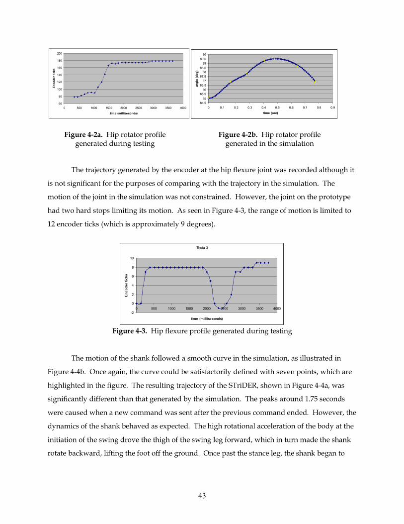
43
60
80
100
120
140
160
180
200
0 500 1000 1500 2000 2500 3000 3500 4000
time (milliseconds)
Enco
der t
icks
84.585
85.586
86.587
87.588
88.589
89.590
0 0.1 0.2 0.3 0.4 0.5 0.6 0.7 0.8 0.9
time (sec)
angl
e (d
eg)
The trajectory generated by the encoder at the hip flexure joint was recorded although it
is not significant for the purposes of comparing with the trajectory in the simulation. The
motion of the joint in the simulation was not constrained. However, the joint on the prototype
had two hard stops limiting its motion. As seen in Figure 4-3, the range of motion is limited to
12 encoder ticks (which is approximately 9 degrees).
Theta 3
-2
0
2
4
6
8
10
0 500 1000 1500 2000 2500 3000 3500 4000
time (milliseconds)
Enco
der t
icks
Figure 4-3. Hip flexure profile generated during testing
The motion of the shank followed a smooth curve in the simulation, as illustrated in
Figure 4-4b. Once again, the curve could be satisfactorily defined with seven points, which are
highlighted in the figure. The resulting trajectory of the STriDER, shown in Figure 4-4a, was
significantly different than that generated by the simulation. The peaks around 1.75 seconds
were caused when a new command was sent after the previous command ended. However, the
dynamics of the shank behaved as expected. The high rotational acceleration of the body at the
initiation of the swing drove the thigh of the swing leg forward, which in turn made the shank
rotate backward, lifting the foot off the ground. Once past the stance leg, the shank began to
*
**
* **
*
Figure 4-2a. Hip rotator profile generated during testing
Figure 4-2b. Hip rotator profile generated in the simulation
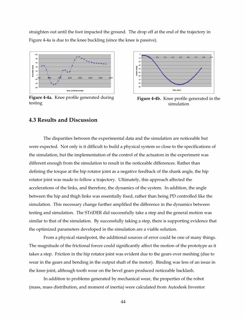
44
straighten out until the foot impacted the ground. The drop off at the end of the trajectory in
Figure 4-4a is due to the knee buckling (since the knee is passive).
-60
-40
-20
0
20
40
60
80
100
500 1000 1500 2000 2500 3000 3500 4000
time (milliseconds)
Enc
oder
tick
s
Figure 4-4a. Knee profile generated during testing 4.3 Results and Discussion
The disparities between the experimental data and the simulation are noticeable but
were expected. Not only is it difficult to build a physical system so close to the specifications of
the simulation, but the implementation of the control of the actuators in the experiment was
different enough from the simulation to result in the noticeable differences. Rather than
defining the torque at the hip rotator joint as a negative feedback of the shank angle, the hip
rotator joint was made to follow a trajectory. Ultimately, this approach affected the
accelerations of the links, and therefore, the dynamics of the system. In addition, the angle
between the hip and thigh links was essentially fixed, rather than being PD controlled like the
simulation. This necessary change further amplified the difference in the dynamics between
testing and simulation. The STriDER did successfully take a step and the general motion was
similar to that of the simulation. By successfully taking a step, there is supporting evidence that
the optimized parameters developed in the simulation are a viable solution.
From a physical standpoint, the additional sources of error could be one of many things.
The magnitude of the frictional forces could significantly affect the motion of the prototype as it
takes a step. Friction in the hip rotator joint was evident due to the gears over meshing (due to
wear in the gears and bending in the output shaft of the motor). Binding was less of an issue in
the knee joint, although tooth wear on the bevel gears produced noticeable backlash.
In addition to problems generated by mechanical wear, the properties of the robot
(mass, mass distribution, and moment of inertia) were calculated from Autodesk Inventor
-90
-80
-70
-60
-50
-40
-30
-20
-10
00 0.1 0.2 0.3 0.4 0.5 0.6 0.7 0.8 0.9
time (sec)
angl
e (d
eg)
Figure 4-4b. Knee profile generated in the simulation
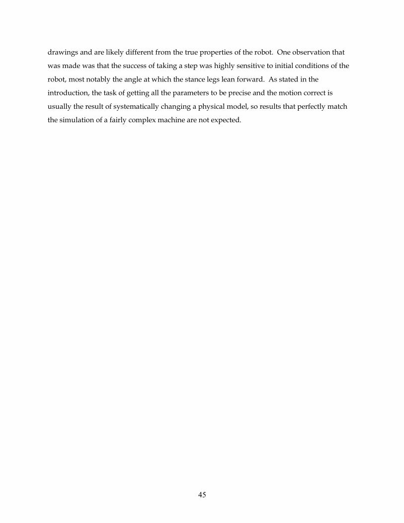
45
drawings and are likely different from the true properties of the robot. One observation that
was made was that the success of taking a step was highly sensitive to initial conditions of the
robot, most notably the angle at which the stance legs lean forward. As stated in the
introduction, the task of getting all the parameters to be precise and the motion correct is
usually the result of systematically changing a physical model, so results that perfectly match
the simulation of a fairly complex machine are not expected.
46
Chapter 5
Conclusions and Recommendations
The goal of the research was to develop the research framework for STriDER, a novel
three-legged robot, including developing a mathematical model and MATLAB simulation of the
2D dynamics, determining the optimal design parameters of the robot, building a prototype
capable of taking multiple steps, and evaluating the performance of a single step.
Various forms of motion generation were considered, but ultimately a method of self-
excited actuation was decided upon due to its flexibility to work across a wide range of design
parameters and the relative simplicity of the controller. Using self-excited actuation, a smooth
step was generated in simulation. Another simulation was developed to determine the optimal
design parameters of the STriDER. Of all the design parameters that could be optimized, the
link lengths of the thigh and shank as well as the center of gravity of the shank were evaluated.
These parameters were shown to have the greatest affect on the motion of the robot.
The first prototype of the STriDER was designed for multiple steps even though the
scope of the research was one step. The three legs of the STriDER are identical, each with four
degrees of freedom; three at the hip and one at the knee. Two of the joints, the hip flexure joint
and the knee joint are kinematically identical, so the same design was implemented in both.
The design consisted of a three bevel gear gearset with the center gear fixed. The motor and
encoder, attached to the same housing, rotated around the stationary gear through 300 degrees
of rotation. A key feature of the hip rotator joint is a hole through the center of the driveshaft,
which allows for electrical connections to pass from the lower portions of the leg through a slip
ring, located on the interior of the body. The hip abductor joints of the stance legs were fixed
for a single step.
Testing revealed several design problems of the robot. Plastic gears, while rated for
loading under normal conditions, wore down under continuous testing. Worn down gears led
to intermittent motion as gears engaged and disengaged, backlash between the gears in the
flexure and knee joint, and additional friction in the system as gears bound. Future
47
implementation of the design should incorporate metal gears and the other design revisions
recommended in chapter 3.
The goal of testing was not only to test the robustness of the design, but also to
investigate the implementation of the AllMotion motor controllers and to validate the results of
the optimization simulation. The implementation of the AllMotion motor controllers proved to
be challenging. Although RS485 is supposed to be fairly immune to the affects of noise, many
problems arose when low current power wires ran parallel to signal wires. The solution was in
cable management; simply moving the wires an inch apart from one another was enough to
solve the problem. When trying to retrieve data from the controllers, the low baud rate of the
controllers limited how many data points were taken. Fast motions, like that of the thigh and
shank of the swing leg at the beginning of the step, generated points spaced far apart from one
another.
The STriDER did successfully take a step and could do so repeatedly once the Labview
program was tuned. The goal of the research was not to match the trajectories of the joints to
those of the simulation, but rather to validate the optimized parameters that were calculated in
the simulation. The control of the motors in testing was different enough from the simulation to
affect the dynamics of the system, which contributed to the largest disparities between the
motions. Furthermore, the constraints placed on the hip flexure joint of the swing leg, while
necessary to ensure the operation of the robot, were not present in the simulation creating more
differences between the motions. Also, the simulation is based on parameters which are easy to
specify but difficult to implement in a physical system. Motor friction and true physical
properties such as mass, mass distribution, moment of inertia are difficult to measure. The
success of a step is highly sensitive to the initial conditions and only after several trial and error
approaches could a configuration be found that would consistently produce a step.
Although some aspects of the design, such as continuously rotating joints, are not found
in nature, researchers must look beyond nature to examine new forms of legged locomotion.
The STriDER has demonstrated that a tripedal robot can move in a manner that is as fluid and
natural as bipedal walking robots. Additionally, the STriDER is inherently stable with three
legs acting as a tripod, even when standing still. The STriDER prototype will act as the
foundation for future three legged robotic research at RoMeLa, including 3D dynamic and
kinematic analysis, advanced control methods, and path planning.
48
References [1] Hong, D. W. and Cipra, R. J., “Optimal Force Distribution for Climbing Tethered Mobile
Robots in Unstructured Environments,” 27th ASME Mechanisms and Robotics Conference, Montreal, Canada, September 30-October 2, 2002.
[2] Hong, D. W. and Cipra, R. J., “Analysis and Visualization of the Contact Force Solution
Space for Multi-Limbed Mobile Robots with Three Feet Contact,” 29th ASME Design Automation Conference, Chicago, IL, September 2-6, 2003.
[3] Hong, D. W. and Cipra, R. J., “Choosing the Optimal Contact Force Distribution for Multi-
Limbed Mobile Robots with Three Feet Contact,” 29th ASME Design Automation Conference, Chicago, IL, September 2-6, 2003.
[4] Song, S.-M., Waldron, R. J., “Geometric Design of a Walking Machine for Optimal
Mobility,” ASME Journal of Mechanisms, Transmissions and Automation in Design, Vol. 109, No. 1, 1987.
[5] Bares, J. and Wettergreen, D., “Dante II: Technical Description, Results and Lessons
Learned,” International Journal of Robotics Research, Vol. 18, No. 7, July 1999, pp. 621-649. [6] Russell, Jr., M., “Odex 1: The first functionoid,” Robotics Age, 5(5), 1983, pp. 12-18. [7] Wettergreen, D., Thomas, H. and Thorpe, C., “Planning strategies for the Ambler walking
robot,” IEEE International Conference on Systems Engineering, pp.198-203, Pittsburgh, PA, USA, Aug 1990.
[8] Hirose, S., Yoneda, K., and Tsukagoshi, H., “TITAN VII: Quadruped walking and
manipulating robot on a steep slope,” Proceedings of International Conference on Robotics and Automation, Albuquerque, New Mexico, 1997, pp. 494-500.
[9] Hirai, K., Hirose, M., Haikawa, Y., and Takenaka T., “The Development of Honda
Humanoid Robot,” IEEE International Conference on Robotics and Automation, Leuven, Belgium, 1998, pp. 1321–1326.
[10] Hirose, M., Haikawa, Y., and Takenaka T., and Hirai, K., “Development of Humanoid
Robot ASIMO,” in IEEE/RSJ International Conference on Intelligent Robots and Systems, Workshop 2, Maui, Hawaii, 2001.
[11] Kato, T., Takanishi, A., Naito, G., and Kato, I., “The realization of the quasi-dynamic
walking by the biped walking machine,” In Proceedings of the International Symposium on Theory and Practice and Manipulators, ROMANSY, 1981, pp. 341–351.
49
[12] Miyazaki, F., and Arimoto, S., “A control theoretic study on dynamical biped locomotion. Transactions of the ASME, Journal of Dynamic Systems, Measurement, and Control 102(4), 1980, pp. 233–239.
[13] Furusho, J., and Masubuchi, M., “Control of a dynamical biped locomotion system for
steady walking,” Transactions of the ASME, Journal of Dynamic Systems, Measurement, and Control 108(2), 1986, pp. 111–118.
[14] McGeer, T., “Passive dynamic walking,” International Journal of Robotics Research, Vol. 9,
No. 2, pp. 62-82, April 1990 [15] Collins, S. H., Wisse, M., Ruina, A., “A Three-Dimensional Passive-Dynamic Walking
Robot with Two Legs and Knees,” International Journal of Robotics Research, Vol. 20, No. 2, pp. 607-615, 2001
[16] Tedrake, R., Zhang, T., Fong, M., Seung, H., “Actuating a Simple 3D Passive Dynamic
Walker,” Proceedings of the IEEE International Conference on Robotics and Automation, New Orleans, LA, April 2004, Vol. 5, pp. 4656-4661.
[17] McGeer, T., “Passive walking with knees,” IEEE International Conference on Robotics and
Automation, 3, pp. 1640-1645, 1990 [18] McGeer, T., “Principles of walking and running,” Chapter 4, Advances in Comparative and
Environmental Physiology, Vol. 11, Springer-Verlag, 1992 [19] McGeer, T., “Dyanamics and control of bipedal locomotion,” Journal of Theoretical
Biology, 163, pp. 277-314, 1993 [20] Collins, S. H. and Ruina, A., “A bipedal walking robot with efficient and human-like gait,”
Proceedings of the IEEE International Conference on Robotics and Automation, Barcelona, Spain,
[21] Spong, M. W. and Bhatia, G., “Further results on control of the compass gait biped,”
International Conference on Intelligent Robots and Systems ,2003, Las Vegas, Nevada, October 27-30, 2003, pp. 1933-1938.
[22] Ono, K., Takahashi, R., and Shimada, T., “Self-excited walking of a biped mechanism,”
International Journal of Robotics Research, 20(12), 2001, pp. 953–966. [23] Irie, T., Hirose, T., and Itoh, K., “Study of three-legged-robot using genetic algorithms,”
Transactions of the Japan Society for Computational Engineering and Science, Edition 2000, No. 20000032, May 24, 2000.
[24] Lee, Y. and Hirose, S., “Three-legged walking for fault-tolerant locomotion of demining
quadruped robots,” Advanced Robotics, Vol. 16, No. 5, August 2002, pp. 415- 426.
50
[25] Frutiger, D. R., Bongard, J. C., and Iida, F., “Iterative Product Engineering: Evolutionary Robot Design,” Proceedings of the Fifth International Conference on Climbing and Walking Robots, 2002, pp. 619-629.
[26] Chatterjee, R., Nagai, M., and Matsuno, F., “Development of modular legged robots: study
with three-legged robot modularity,” Proceedings of 2004 IEEE/RSJ International Conference on Intelligent Robots and Systems, Vol. 2, 28 Sept.-2 Oct., 2004 pp.1450-1455.
[27] Allen, T., Quinn, R. D., Bachmann, R. J., Ritzman, R. E., “Abstracted Biological Principles
Applied with Reduced Actuation Improve Mobility of Legged Vehicles,” Proceedings of the 2003 IEEE/RSJ International Conference on Intelligent Robots and Systems, Las Vegas, NV, Oct. 2003, pp. 1370-1375.
[28] Spong, M., "The Swing Up Control Problem For The Acrobot", IEEE Control Systems
Magazine, Vol. 15, pp. 49-55, February, 1995
[29] Tesar, Delbert. October 18, 1994. Robot and Robot Actuator Module Therefor. US Patent 5355743
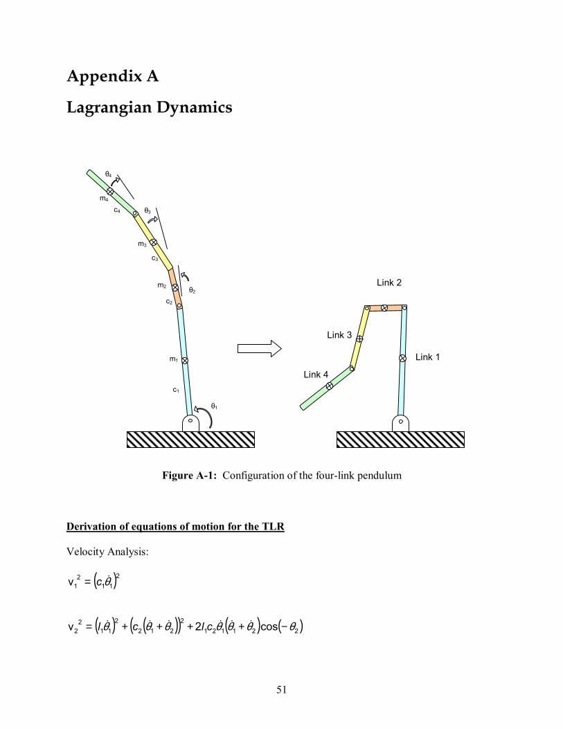
51
Appendix A
Lagrangian Dynamics
Figure A-1: Configuration of the four-link pendulum Derivation of equations of motion for the TLR Velocity Analysis:
( )2112
1v θ&c=
( ) ( )( ) ( ) ( )2211212
2122
112
2 cos2v θθθθθθθ −++++= &&&&&& clcl
m1
θ1
θ2
c1
c2
m2
m3
m4
θ3
θ4
c3
c4
Link 1
Link 2
Link 3
Link 4
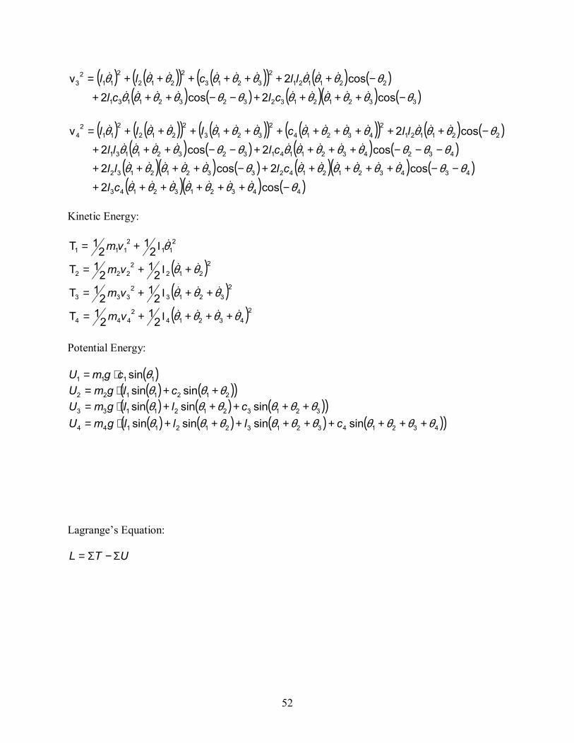
52
( ) ( )( ) ( )( ) ( ) ( )( ) ( ) ( )( ) ( )3321213232321131
2211212
32132
2122
112
3
cos2cos2
cos2v
θθθθθθθθθθθθθθθθθθθθθθ
−++++−−+++
−+++++++=&&&&&&&&&
&&&&&&&&&
clclllcll
( ) ( )( ) ( )( ) ( )( ) ( ) ( )
( ) ( ) ( ) ( )( )( ) ( ) ( )( ) ( )( )( ) ( )4432132143
434321214233212132
432432114132321131
2211212
432142
32132
2122
112
4
cos2
cos2cos2cos2cos2
cos2v
θθθθθθθθθθθθθθθθθθθθθθ
θθθθθθθθθθθθθθθθθθθθθθθθθθθθ
−++++++
−−+++++−++++
−−−++++−−+++
−+++++++++++=
&&&&&&&
&&&&&&&&&&&
&&&&&&&&&
&&&&&&&&&&&&&
clclll
clllllclll
Kinetic Energy:
211
2111 2
12
1T θ&Ι+= vm
( )22122
222 21
21T θθ && +Ι+= vm
( )232132
333 21
21T θθθ &&& ++Ι+= vm
( )2432142
444 21
21T θθθθ &&&& +++Ι+= vm
Potential Energy:
( )1111 sin θcgmU ⋅= ( ) ( )( )2121122 sinsin θθθ ++⋅= clgmU ( ) ( ) ( )( )32132121133 sinsinsin θθθθθθ +++++⋅= cllgmU ( ) ( ) ( ) ( )( )4321432132121144 sinsinsinsin θθθθθθθθθθ +++++++++⋅= clllgmU
Lagrange’s Equation:
UTL Σ−Σ=

53
( ) ( ) ( )( ) ( ) ( )
( ) ( ) ( ) ( )( )( ) ( ) ( )
( ) ( ) ( )( ) ( ) ( ) ( )( ) ( ) ( )( ) ( )
( )( ) ( ) ( )( ) ( )( ) ( ) ( )
( ) ( ) ( ) ( )( ) ( )432144
321343321242322
1141312112
43214
4432132143443432121424
33212132443243211414
3232113142211214
24321
244
2321
234
221
224
21
214
23213332121323
3232113132211213
2321
233
221
223
21
213
2212
22112122
212
222
12
122
112
12
11
sinsinsin
sin21
coscoscoscos
coscos2
12
12
12
12
1cos
coscos2
12
12
12
1
cos21
21
21
21
θθθθθθθθθ
θθθθθ
θθθθθθθθθθθθθθθθθθθθθθθθθθθθθθ
θθθθθθθθθθ
θθθθθθθθθ
θθθθθθθθθθ
θθθθθθθθθθ
θθθθθθθθ
θθθθθθθθθ
+++⋅−++⋅+−+⋅++−
⋅+++−+++Ι+
−++++++−−+++++
−++++−−−++++
−−+++−++
+++++++++
+++Ι+−++++
−−+++−++
+++++++Ι+
−+++++Ι+=
gcmglmcmglmlmcm
glmlmlmcm
clmclmllmclm
llmllm
cmlmlm
lmclm
clmllm
cmlmlm
clmcmlmcmL
&&&&
&&&&&&&&&&&&&
&&&&&&&&&&
&&&&&&&
&&&&&&&&&
&&&&&&&&&
&&&&&&&
&&&&&&&&
&&&&&&&&
Derivation of EOM:
∗=−
i
ii
QqL
qL
dtd
δδ
δδ&
EOM for θ1 :
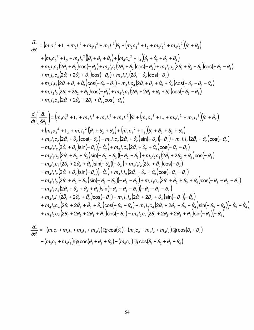
54
( ) ( )( )
( )( ) ( )( )( ) ( ) ( ) ( )( ) ( ) ( )( ) ( )( ) ( ) ( )( ) ( )( ) ( ) ( )( ) ( )( ) ( ) ( )
( ) ( )( ) ( ) ( )( ) ( )( ) ( ) ( )( ) ( )( )( ) ( ) ( ) ( )( )( ) ( ) ( ) ( )( )( ) ( ) ( ) ( )( )44432143444321434
43434321424434321424
333213243321324
4324324321414
43243214143232321314
323213142221214
22121433321323
33213233232321313
323213132221213
2212132221212221212
432142
443212
3432
33
212
242
2322
2212
142
132
1212
111
sin222cos222sin22cos22
sin22cos22sin2
cos2sin2cos2sin2
cos2sin22cos22sin2
cos2sin2cos2sin2cos2
θθθθθθθθθθθθθθθθθθθθθθθθθ
θθθθθθθθθθθθθθθθθθθ
θθθθθθθθθθθθθθθθθθθθθθθ
θθθθθθθθθθθθθθθθθθθ
θθθθθθθθθθθθθθθθθθθ
θθθθθθθ
θθθθδ
δ
&&&&&&&&&&&&&
&&&&&&&&&&&&&&
&&&&&&&&&&
&&&&&&&
&&&&&&&&&&&&&
&&&&&&&&&
&&&&&&&&
&&&&&&&&&&&
&&&&&&&&&
&&&&&&&&&&&
&&&&&&&&&&&&&&
&&&&&&&
−−+++−−++++
−−−−+++−−−++++
−−++−−+++
−−−−−−+++−
−−−++++−−−−++−
−−+++−−+−
−++−−++−
−+++−−−−++−
−−+++−−+−
−++−−+−−++
+++Ι+++++Ι++
+++Ι+++++Ι+=
clmclmclmclm
llmllmclm
clmllmllmllm
llmclmclmclm
clmllmllmclmclm
cmlmcm
lmlmcmlmlmlmcmLdtd
( ) ( ) ( ) ( )
( ) ( ) ( ) ( )4321443213433
212423221141312111
coscos
coscos
θθθθθθθ
θθθδθδ
+++⋅−++⋅+−
+⋅++−⋅+++−=
gcmglmcm
glmlmcmglmlmlmcmL
( ) ( )( )( )( ) ( )( )
( ) ( ) ( ) ( ) ( ) ( )( ) ( ) ( ) ( )
( ) ( ) ( ) ( )( ) ( ) ( ) ( )( ) ( )44321434
4343214243321324
432432141432321314
2212143321323
32321313221213221212
432142
443212
3432
33
212
242
2322
2212
142
132
1212
111
cos222cos22cos22
cos2cos2cos2cos22
cos2cos2cos2
θθθθθθθθθθθθθθθ
θθθθθθθθθθθθθθθθθθθ
θθθθθθθθθθθθθθθθθθ
θθθθδ
δ
−++++
−−++++−+++
−−−++++−−+++
−++−+++
−−+++−++−++
+++Ι+++++Ι++
+++Ι+++++Ι+=
&&&&
&&&&&&&
&&&&&&&
&&&&&
&&&&&&&
&&&&&&&
&&&&
clmclmllmclmllm
llmclmclmllmclm
cmlmcm
lmlmcmlmlmlmcmL
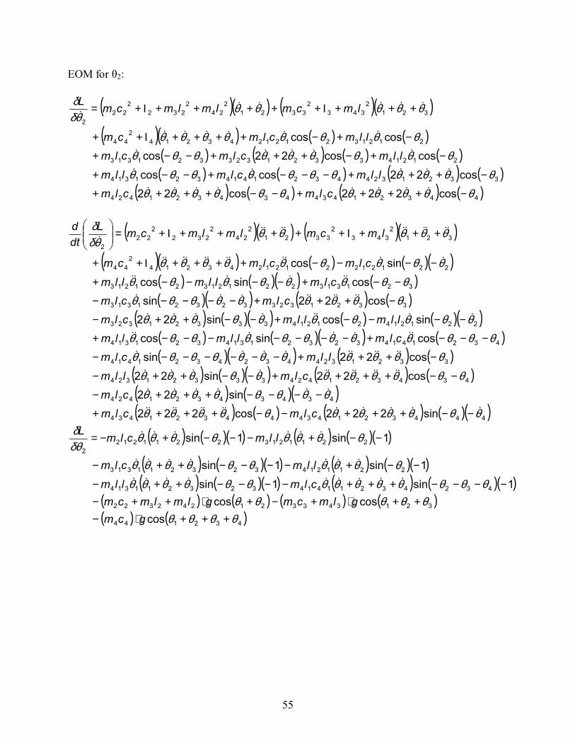
55
EOM for θ2:
( )( ) ( )( )( )( ) ( ) ( )( )
( ) ( )( ) ( )( )( ) ( ) ( )
( ) ( )( ) ( ) ( )( )( ) ( )( ) ( )( )( ) ( ) ( )
( ) ( )( ) ( ) ( )( ) ( )( )( ) ( ) ( ) ( )( )44432143444321434
43434321424
43432142433321324
33213244324321414
432141432321314321314
2212142121433321323
332132332321313
32131322121321213
22121221212432142
44
3212
3432
33212
242
2322
222
sin222cos222sin22
cos22sin22
cos22sincossincossincossin22
cos22sincossincos
sincos
θθθθθθθθθθθθθθθθθθθ
θθθθθθθθθθθθθθθθθθθθθθ
θθθθθθθθθθθθθθθθθθθθθθ
θθθθθθθθθθθθθθθθθ
θθθθθθθθθ
θθθθθθδδ
&&&&&&&&&&&&&
&&&&&&
&&&&&&&&&&&&
&&&&&&&&&&
&&&&&&&
&&&&&&&&
&&&&&&&&&
&&&&&&
&&&&&&&&&&&&
&&&&&&&&&&&
−−+++−−++++
−−−−+++−
−−++++−−++−
−+++−−−−−−−
−−−+−−−−−−−+
−−−−+−−++−
−+++−−−−−
−−+−−−−+
−−−−++++Ι++
+++Ι+++++Ι+=
clmclmclm
clmllmllmclm
clmllmllmllmllmclm
clmclmclmllmllm
clmclmcm
lmcmlmlmcmLdtd
( ) ( )( ) ( ) ( )( )
( ) ( )( ) ( ) ( )( )( ) ( )( ) ( ) ( )( )
( ) ( ) ( ) ( )( ) ( )432144
321343321242322
43243211414323211314
2211214323211313
221121322112122
coscoscos
1sin1sin
1sin1sin
1sin1sin
θθθθθθθθθ
θθθθθθθθθθθθθθθθθθθθθθθθ
θθθθθθθθδθδ
+++⋅−++⋅+−+⋅++−
−−−−+++−−−−++−
−−+−−−−++−
−−+−−−+−=
gcmglmcmglmlmcm
clmllmllmclm
llmclmL
&&&&&&&&&
&&&&&&&
&&&&&&
( )( ) ( )( )( )( ) ( ) ( )
( ) ( ) ( ) ( )( ) ( ) ( ) ( )
( ) ( ) ( ) ( )44321434434321424
33213244321414321314
212143321323321313
2121321212432142
44
3212
3432
33212
242
2322
222
cos222cos22cos22coscos
coscos22coscoscos
θθθθθθθθθθθθθθθθθθθθθθ
θθθθθθθθθθθθθθθθθ
θθθθθθδδ
−++++−−++++
−+++−−−+−−+
−+−+++−−+
−+−++++Ι++
+++Ι+++++Ι+=
&&&&&&&&
&&&&&
&&&&&
&&&&&&
&&&&&&
clmclmllmclmllm
llmclmclmllmclmcm
lmcmlmlmcmL
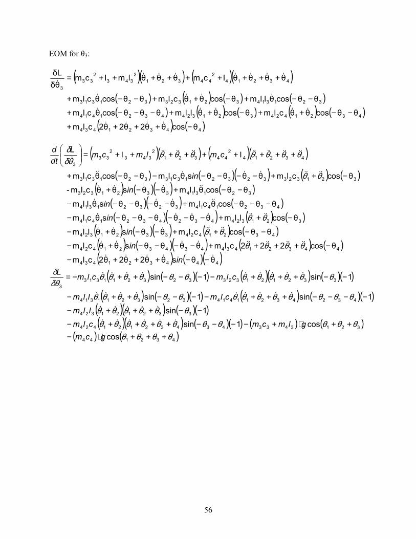
56
EOM for θ3:
( )( ) ( )( )( ) ( ) ( ) ( )( ) ( ) ( ) ( ) ( )
( ) ( )44321434
43214243213244321414
321314321323321313
432142
443212
3432
333
θcosθθ2θ2θ2clm
θθcosθθclmθcosθθllmθθθcosθclm
θθcosθllmθcosθθclmθθcosθclm
θθθθΙcmθθθlmΙcmθδδL
−++++
−−++−++−−−+
−−+−++−−+
+++++++++=
&&&&
&&&&&
&&&&
&&&&&&&&
( )( ) ( )( )( ) ( )( ) ( ) ( )
( ) ( )( ) ( )( )( ) ( )( )( ) ( ) ( )
( ) ( )( ) ( ) ( )( ) ( )( ) ( ) ( )( ) ( )( )444321434
44321434434321424
43214243321324
3213244324321414
432141432321314
3213143321323
32132332321313321313
432142
443212
3432
333
θθsθθ2θ2θ2clm
θcos222clmθθθθsθθclm
θθcosclmθθsθθllm
θcosllmθθθθθθsθclm
θθθcosθclmθθθθsθllm
θθcosθllmθθsθθclm-
θcosclmθθθθsθclmθθcosθclm
&&&&&
&&&&&&&&&&&&
&&&&&&&
&&&&&&&&
&&&&&
&&&&&
&&&&&&&&&
&&&&&&&&&&&&&&&
−−+++−
−++++−−−−+−
−−++−−+−
−++−−−−−−−
−−−+−−−−−
−−+−−+
−++−−−−−−−+
+++Ι+++++Ι+=
in
in
in
in
in
in
in
cmlmcmLdtd
θθθθθθ
θθ
θθ
θθθθθθθθδδ
( ) ( )( ) ( )( ) ( )( )
( ) ( )( ) ( ) ( )( )( )( ) ( )( )( )( ) ( )( ) ( ) ( )
( ) ( )432144
321343343432121424
332121324
43243211414323211314
3321213233232113133
coscos1sin
1sin
1sin1sin
1sin1sin
θθθθθθθθθθθθθθθ
θθθθθθθθθθθθθθθθθθθθ
θθθθθθθθθθθθδθδ
+++⋅−++⋅+−−−−++++−
−−+++−
−−−−+++−−−−++−
−−+++−−−−++−=
gcmglmcmclm
llmclmllm
clmclmL
&&&&&&
&&&&&
&&&&&&&&&
&&&&&&&&&
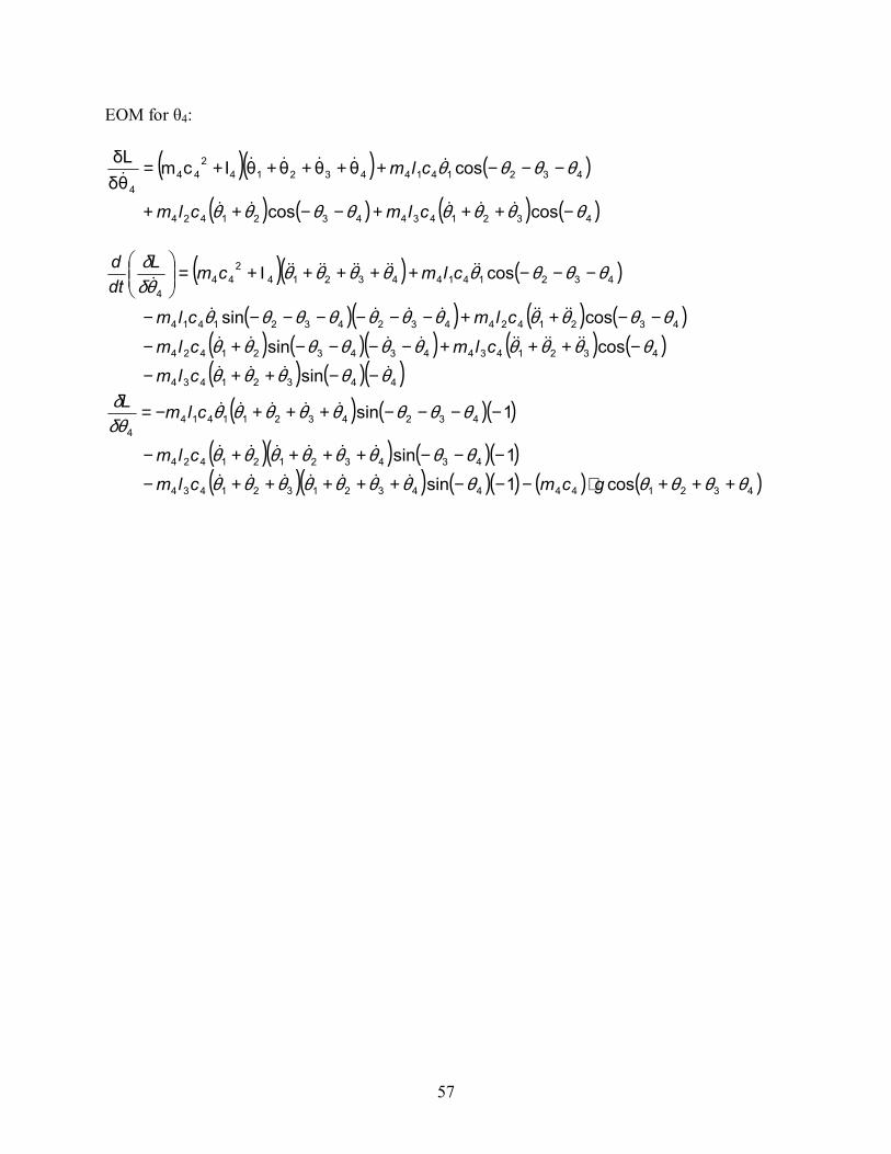
57
EOM for θ4:
( )( ) ( )
( ) ( ) ( ) ( )43214344321424
4321414432142
444
coscos
cosθθθθΙcmθδδL
θθθθθθθθ
θθθθ
−+++−−++
−−−+++++=
&&&&&
&&&&&&
clmclm
clm
( )( ) ( )
( )( ) ( ) ( )( ) ( )( ) ( ) ( )( ) ( )( )44321434
4321434434321424
43214244324321414
4321414432142
444
sincossin
cossin
cos
θθθθθθθθθθθθθθθ
θθθθθθθθθθθ
θθθθθθθθθδδ
&&&&
&&&&&&&&&&
&&&&&&&&
&&&&&&&&&&&
−−++−
−+++−−−−+−
−−++−−−−−−−
−−−++++Ι+=
clmclmclmclmclm
clmcmLdtd
( ) ( )( )
( )( ) ( )( )( )( ) ( )( ) ( ) ( )43214444321321434
43432121424
432432114144
cos1sin1sin
1sin
θθθθθθθθθθθθθθθθθθθθ
θθθθθθθθδθδ
+++⋅−−−+++++−
−−−++++−
−−−−+++−=
gcmclmclm
clmL
&&&&&&&
&&&&&&
&&&&&
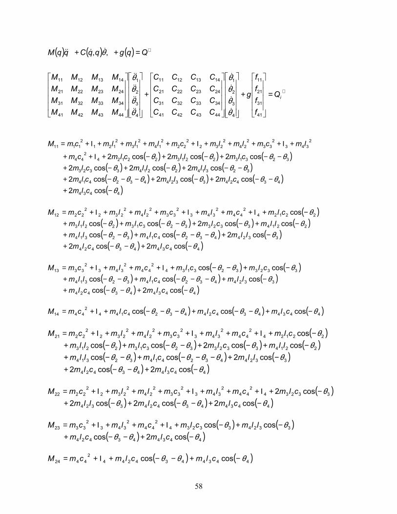
58
( ) ( ) ( )
∗
∗
=
+
+
=++
iQ
ffff
g
CCCCCCCCCCCCCCCC
MMMMMMMMMMMMMMMM
QqgqqCqqM
41
31
21
11
4
3
2
1
44434241
34333231
24232221
14131211
4
3
2
1
44434241
34333231
24232221
14131211
,,
θθθθ
θθθθ
θ
&
&
&
&
&&
&&
&&
&&
&&&&
( ) ( ) ( )( ) ( ) ( )( ) ( ) ( )( )4434
434243324432414
3231422143323
323132213221242
44
2343
233
224
2232
222
214
213
2121
21111
cos2cos2cos2cos2
cos2cos2cos2cos2cos2cos2
θθθθθθθ
θθθθθθθθ
−+−−+−+−−−+
−−+−+−+−−+−+−+Ι++
+Ι++++Ι+++++Ι+=
clmclmllmclm
llmllmclmclmllmclmcm
lmcmlmlmcmlmlmlmcmM
( )
( ) ( ) ( ) ( )( ) ( ) ( )
( ) ( )443443424
332443241432314
22143323323132213
221242
442
3432
332
242
2322
2212
cos2cos2cos2coscos
coscos2coscoscos
θθθθθθθθθ
θθθθθθ
−+−−+−+−−−+−−+
−+−+−−+−+−+Ι+++Ι++++Ι+=
clmclmllmclmllm
llmclmclmllmclmcmlmcmlmlmcmM
( ) ( )
( ) ( ) ( )( ) ( )443443424
332443241432314
33233231342
442
3432
3313
cos2coscoscoscos
coscos
θθθθθθθθθ
θθθ
−+−−+−+−−−+−−+
−+−−+Ι+++Ι+=
clmclmllmclmllm
clmclmcmlmcmM
( ) ( ) ( )4434434244324144
24414 coscoscos θθθθθθ −+−−+−−−+Ι+= clmclmclmcmM
( )
( ) ( ) ( ) ( )( ) ( ) ( )
( ) ( )443443424
332443241432314
22143323323132213
221242
442
3432
332
242
2322
2221
cos2cos2cos2coscos
coscos2coscoscos
θθθθθθθθθ
θθθθθθ
−+−−+−+−−−+−−+
−+−+−−+−+−+Ι+++Ι++++Ι+=
clmclmllmclmllm
llmclmclmllmclmcmlmcmlmlmcmM
( )
( ) ( ) ( )4434434243324
332342
442
3432
332
242
2322
2222
cos2cos2cos2cos2
θθθθθ
−+−−+−+−+Ι+++Ι++++Ι+=
clmclmllmclmcmlmcmlmlmcmM
( ) ( )
( ) ( )443443424
3324332342
442
3432
3323
cos2coscoscos
θθθθθ
−+−−+−+−+Ι+++Ι+=
clmclmllmclmcmlmcmM
( ) ( )4434434244
24424 coscos θθθ −+−−+Ι+= clmclmcmM
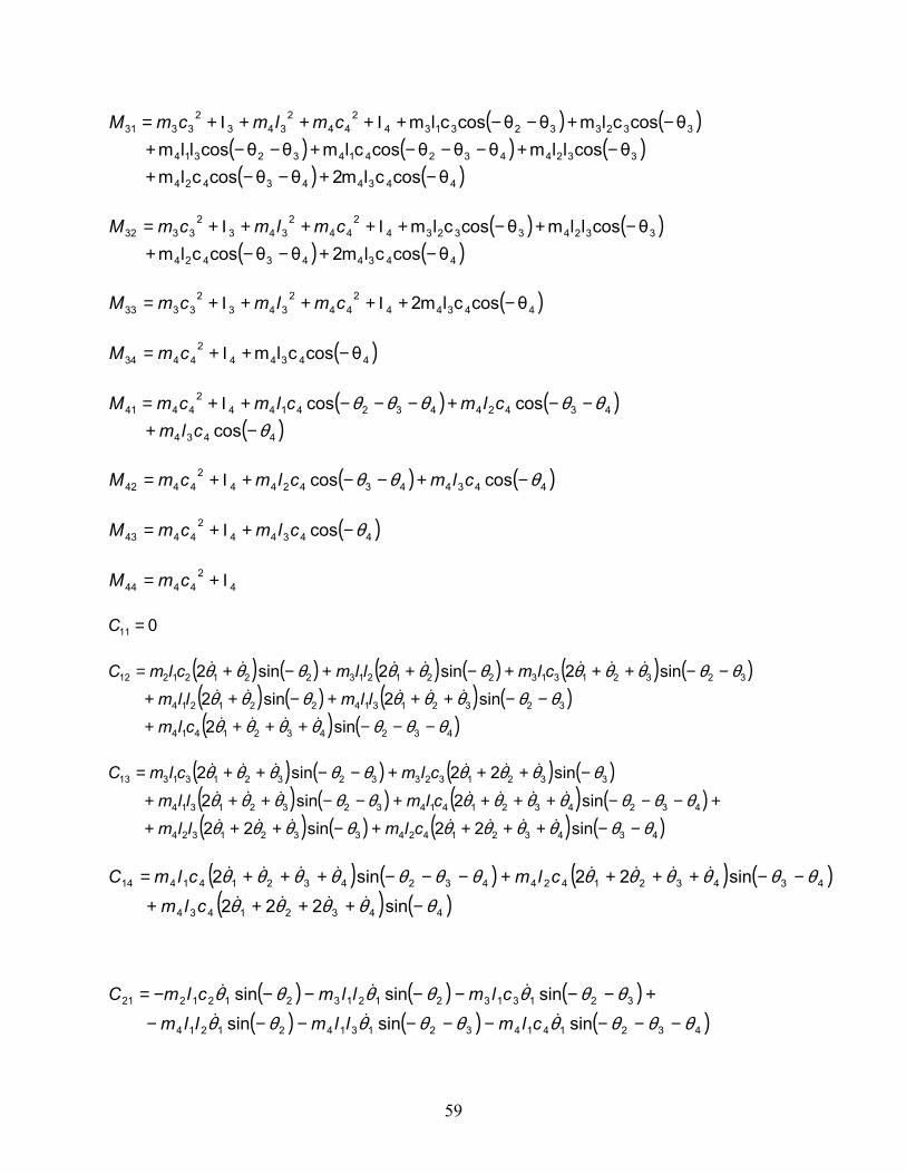
59
( ) ( )( ) ( ) ( )( ) ( )443443424
332443241432314
33233231342
442
3432
3331
θcosclm2θθcosclmθcosllmθθθcosclmθθcosllm
θcosclmθθcosclm
−+−−+−+−−−+−−+
−+−−+Ι+++Ι+= cmlmcmM
( ) ( )
( ) ( )443443424
3324332342
442
3432
3332
θcosclm2θθcosclmθcosllmθcosclm
−+−−+−+−+Ι+++Ι+= cmlmcmM
( )44344
244
2343
23333 θcosclm2 −+Ι+++Ι+= cmlmcmM
( )44344
24434 θcosclm −+Ι+= cmM
( ) ( )
( )4434
4342443241442
4441
coscoscos
θθθθθθ
−+−−+−−−+Ι+=
clmclmclmcmM
( ) ( )4434434244
24442 coscos θθθ −+−−+Ι+= clmclmcmM
( )44344
24443 cos θ−+Ι+= clmcmM
42
4444 Ι+= cmM
011 =C
( ) ( ) ( ) ( ) ( ) ( )( ) ( ) ( ) ( )( ) ( )4324321414
32321314221214
3232131322121322121212
sin2sin2sin2
sin2sin2sin2
θθθθθθθθθθθθθθθ
θθθθθθθθθθθ
−−−++++
−−+++−++
−−+++−++−+=
&&&&
&&&&&
&&&&&&&
clmllmllm
clmllmclmC
( ) ( ) ( ) ( )( ) ( ) ( ) ( )( ) ( ) ( ) ( )4343214243321324
432432141432321314
33213233232131313
sin22sin22sin2sin2
sin22sin2
θθθθθθθθθθθθθθθθθθθθθθ
θθθθθθθθθ
−−++++−+++
+−−−++++−−+++
−+++−−++=
&&&&&&&
&&&&&&&
&&&&&&
clmllmclmllmclmclmC
( ) ( ) ( ) ( )( ) ( )44321434
434321424432432141414
sin222
sin22sin2
θθθθθθθθθθθθθθθθθθ
−++++
−−++++−−−+++=&&&&
&&&&&&&&
clmclmclmC
( ) ( ) ( )( ) ( ) ( )432141432131421214
321313212132121221
sinsinsin
sinsinsin
θθθθθθθθθθθθθθθθ
−−−−−−−−−
+−−−−−−−=&&&
&&&
clmllmllmclmllmclmC
60
022 =C
( ) ( ) ( ) ( )( ) ( )434321424
3321324332132323
sin22
sin22sin22
θθθθθθθθθθθθθθ
−−++++
−+++−++=&&&&
&&&&&&
clmllmclmC
( ) ( ) ( ) ( )4432143443432142424 sin222sin22 θθθθθθθθθθθ −++++−−+++= &&&&&&&& clmclmC
( ) ( ) ( ) ( )( ) ( ) ( ) ( ) ( )43214243213244321414
32131432132332131331
θθsθ2θclmθsθ2θllmθθθsθclm
θθsθllmθsθ2θclm-θθsθclm
−−+−−+−−−−−
−−−−+−−−=
ininin
inininC&&&&&
&&&&
( ) ( ) ( )432424323243232332 θθsθclmθsθllmθsθcl-m −−−−−−= inininC &&&
033 =C
( ) ( )4432143434 θs222clm −+++= inC θθθθ &&&&
( ) ( ) ( )( ) ( )44321434
434321424432141441
sin
sinsin
θθθθθθθθθθθθθθθ
−+++−
−−+++−−−−−=&&&&
&&&&&
clmclmclmC
( ) ( ) ( ) ( )4432143443432142442 sinsin θθθθθθθθθθθ −+++−−−+++−= &&&&&&&& clmclmC
( ) ( )4432143443 sin θθθθθ −+++−= &&&&clmC
044 =C
( ) ( ) ( ) ( )
( ) ( ) ( ) ( )4321443213433
2124232211413121111
coscoscoscos
θθθθθθθθθθ
+++⋅+++⋅+++⋅+++⋅+++=
cmlmcmlmlmcmlmlmlmcmf
( ) ( ) ( ) ( )
( ) ( )432144
32134332124232221
coscoscos
θθθθθθθθθ
+++⋅+++⋅+++⋅++=
cmlmcmlmlmcmf
( ) ( ) ( ) ( )432144321343331 coscos θθθθθθθ +++⋅+++⋅+= cmlmcmf
( ) ( )43214441 cos θθθθ +++⋅= cmf
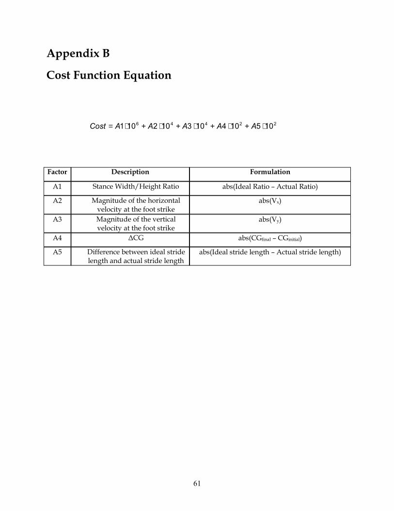
61
Appendix B
Cost Function Equation
Factor Description Formulation
A1 Stance Width/Height Ratio abs(Ideal Ratio – Actual Ratio)
A2 Magnitude of the horizontal velocity at the foot strike
abs(Vx)
A3 Magnitude of the vertical velocity at the foot strike
abs(Vy)
A4 ∆CG abs(CGfinal – CGinitial)
A5 Difference between ideal stride length and actual stride length
abs(Ideal stride length – Actual stride length)
22446 105104103102101 ⋅+⋅+⋅+⋅+⋅= AAAAACost

62
Appendix C
Materials and Parts Suppliers Part Supplier Website EZSV10 1.5A DC Servo Motor Controller AllMotion www.allmotion.com RS232 to RS485 Converter 4-port RS485 EZ Bus Station Plastic Miter Gears BostonGear www.bostongear.com 1/4” miniature ball bearings SPB-USA www.spb-usa.com 5/8” extra thin series ball bearings Port Escap DC motors PortEscap www.portescap.com w/ planetary gearhead
17N78 210E motor w/ 352:1 gearhead 17N78 213E motor w/ 166:1 gearhead
Oak Grigsby Encoders Electro Switch www.electro-nc.com
900 Series Optical Encoders 512 PPR (Pulses Per Revolution)
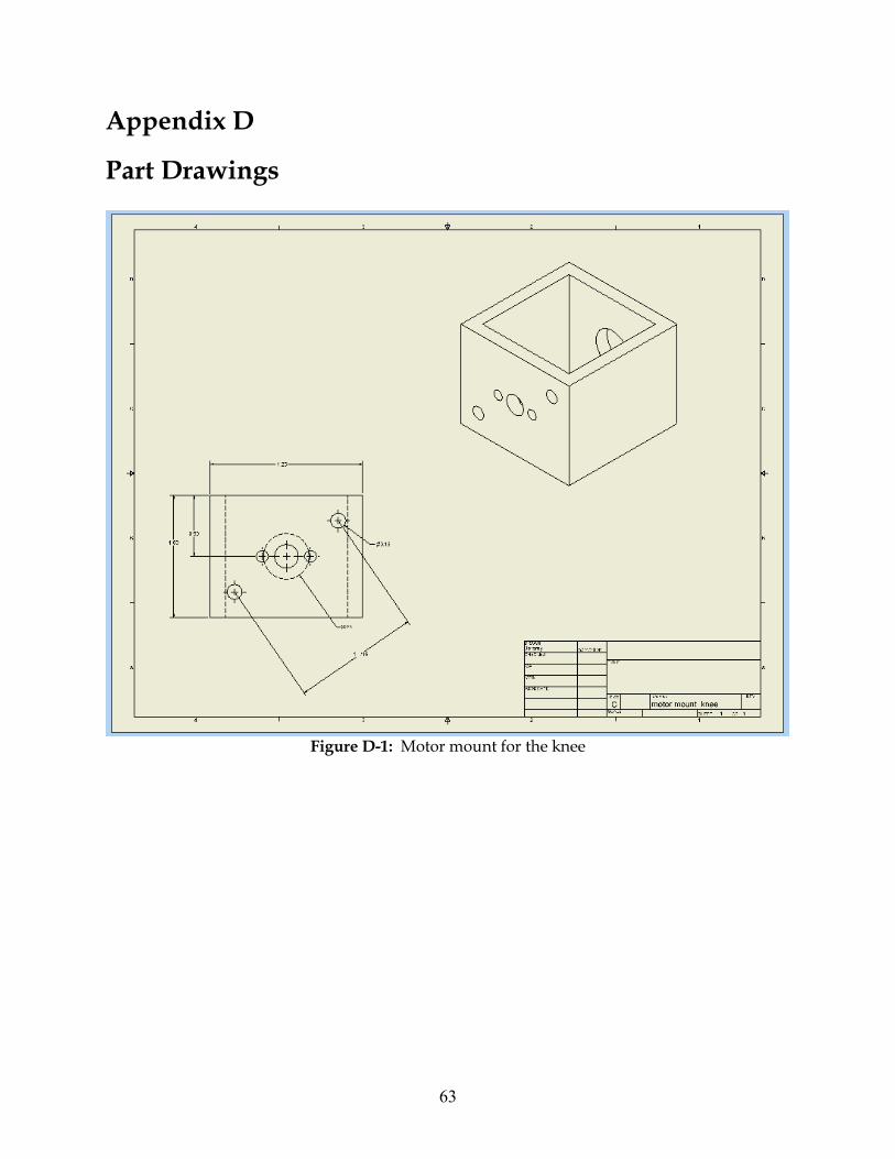
63
Appendix D
Part Drawings
Figure D-1: Motor mount for the knee

64
Figure D-2: Bevel gear mount for the knee
Figure D-3: Hip rotator joint
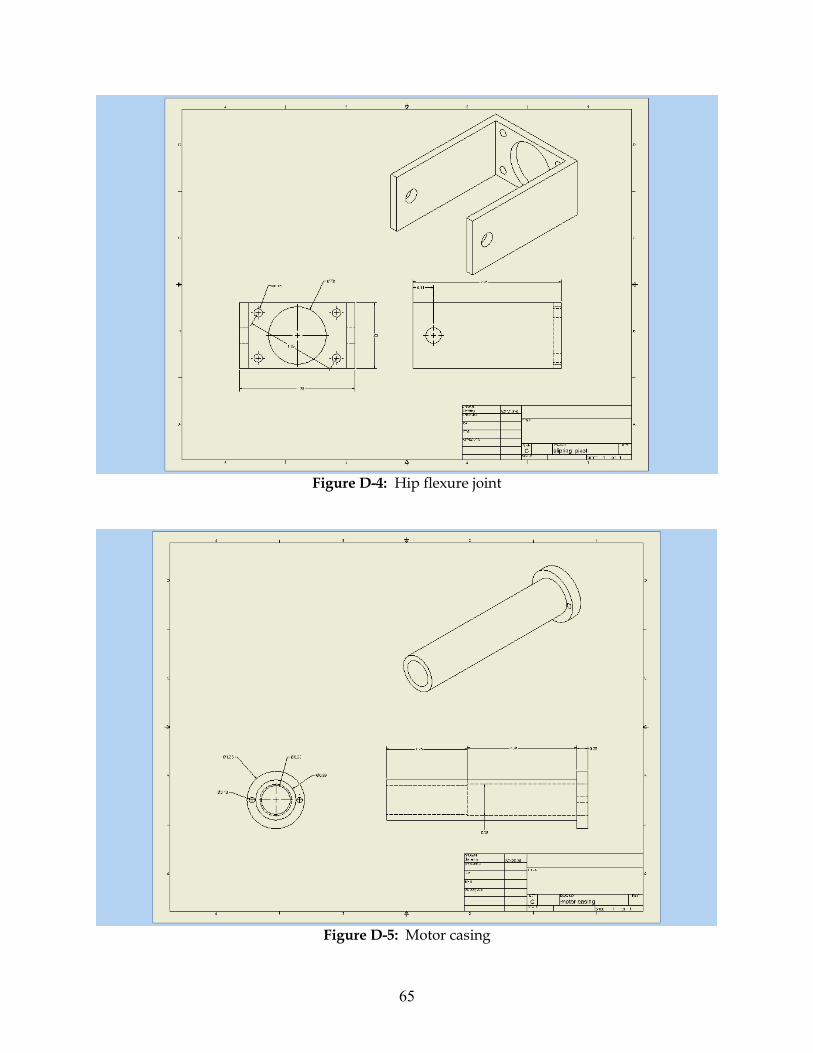
65
Figure D-4: Hip flexure joint
Figure D-5: Motor casing
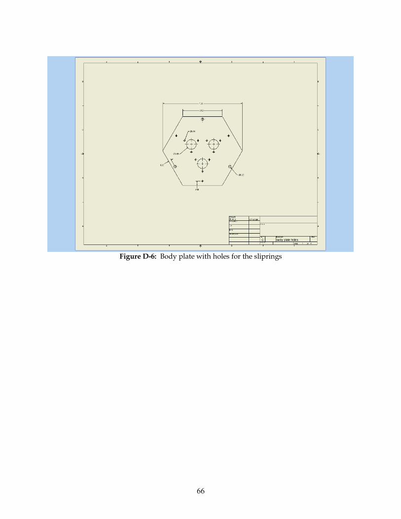
66
Figure D-6: Body plate with holes for the sliprings