Embed Size (px)
Citation preview

Progress In Electromagnetics Research C, Vol. 11, 81–90, 2009
DESIGN OF A NOVEL EBG STRUCTURE AND ITSAPPLICATION IN FRACTAL MICROSTRIP ANTENNA
H. R. Cheng and Q. Y. Song
National Key Laboratory of Antennas and Microwave TechnologyXidian UniversityXi’an, Shaanxi 710071, China
Y. C. Guo
Jiangnan Electronic Communication Research InstituteJiaxing, Zhejiang 314033, China
X. Q. Chen and X. W. Shi
National Key Laboratory of Antennas and Microwave TechnologyXidian UniversityXi’an, Shaanxi 710071, China
Abstract—In this paper, a novel electromagnetic bandgap structure(EBGs) is proposed, which is similar to the mushroom-like EBG. Byintroducing double reverse split rings (RSR) into the square patch,the size of EBG cell is reduced by 30%, and the bandgap achievesbandwidth about 65%. A fractal microstrip antenna is implementedusing the EBGs as a ground plane, and the measured results show thatthe reduction in the surface wave level is remarkable. Compared withthe reference antenna at 5 GHz, an approximately 8 dB improvementof the return loss is achieved, and the back lobe is reduced by 10 dB inE plane and 8.73 dB in H plane at the resonant frequency, respectively.The front-back ratios of the antenna have significantly increased from4.9GHz to 5.2 GHz.
Corresponding author: H. R. Cheng ([email protected]).

82 Cheng et al.
1. INTRODUCTION
Recently, there has been much interest in investigating electromagneticbandgap structures or photonic band gap structures (PBGs) [1, 2].Varieties of EBGs have been proposed and studied, because the EBGsrepresent some unique characteristics, such as forbidden bandgap, in-phase reflection, etc. [3]. It has been reported that EBGs used inmicrostrip antenna community can improve characteristics of antennas,such as improving their radiation patterns, enhancing their gain, andminimizing the side and back lobe levels, etc. [4–6]. Since the period ofan EBG lattice has to be a half-wavelength at the stopband frequencyin early EBG design, the EBGs usually have difficulty in practicalapplications accommodating its physical size. So many small andcompact periodic EBGs have been investigated to solve this problem,such as mushroom-like EBG [7], UC-PBG [8], fork-like EBG [9]and spiral-like EBG [10]. The mushroom-like EBGs known as highimpedance surface (HIS) is initially proposed by Sievenpiper, whichis made up of metal patches, dielectric substrate, and vias connectedwith patches and ground plane, as shown in Figure 1. The mushroom-like EBGs have a frequency bandgap and very high surface impedancecharacteristics, which is generally called in-phase reflection band. Thisconventional mushroom-like EBGs can be used in antenna design tosuppress the propagating of surface wave, but the cell size is still toolarge to be used in some practical applications. Thereby, it is necessaryto investigate the smaller EBGs for widely using in antenna fields.
This paper presents a novel reverse split rings EBGs, which isbased on the conventional EBGs. The size of EBG cell is reduced byintroducing double reverse split rings into the square patch. Comparedwith the conventional EBGs, the size of the RSR EBG cell is reducedby 30%, and the bandgap achieves bandwidth about 65%. To verify thedeign, two fractal microstrip patch antennas with and without EBGsare constructed and simulated by Ansoft HFSS 11. The results showthat the reduction in the surface wave level is remarkable.
2. RSR EBG SUBSTRATE AND CHARACTERIZATION
2.1. Design of the RSR EBG Structure
As it is shown, when the periodicity is small compared to theoperating wavelength, the EBGs can be simply modeled as a parallelLC equivalent circuit. The capacitance C is determined by thefringing capacitance between neighboring metal patches, while thecurrent flowing through the via and metal plate, can be consideredas inductance L, as demonstrated in Figure 1.
Progress In Electromagnetics Research C, Vol. 11, 2009 83
(a) (b)
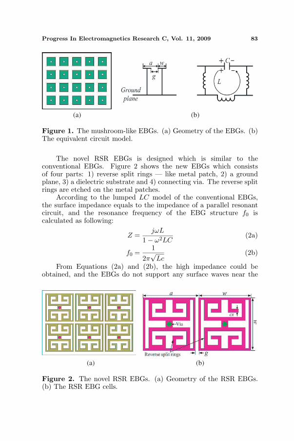
Figure 1. The mushroom-like EBGs. (a) Geometry of the EBGs. (b)The equivalent circuit model.
The novel RSR EBGs is designed which is similar to theconventional EBGs. Figure 2 shows the new EBGs which consistsof four parts: 1) reverse split rings — like metal patch, 2) a groundplane, 3) a dielectric substrate and 4) connecting via. The reverse splitrings are etched on the metal patches.
According to the lumped LC model of the conventional EBGs,the surface impedance equals to the impedance of a parallel resonantcircuit, and the resonance frequency of the EBG structure f0 iscalculated as following:
Z =jωL
1− ω2LC(2a)
f0 =1
2π√
Lc(2b)
From Equations (2a) and (2b), the high impedance could beobtained, and the EBGs do not support any surface waves near the
(a) (b)
Figure 2. The novel RSR EBGs. (a) Geometry of the RSR EBGs.(b) The RSR EBG cells.

84 Cheng et al.
resonance frequency, resulting in a frequency bandgap. The inductanceL and capacitance C are given by the following equations [11]:
L = µ0µrh (2c)
C =wε0(1 + εr)
πcosh−1
(a
g
)(2d)
where µ0 and ε0 are the permeability and permittivity of free space,respectively. The EBG cell is determined by the parameters: a is thegrid period; g is the gap width; w is the patch width; h is the thicknessof the substrate; εr is the relative permittivity. The bandwidth BWof bandgap can be determined by the surface capacitance C andinductance L:
BW =1η
√L
C(2e)
where η is the free space impedance, which is 120π. In order to increasethe equivalent inductance, a new approach is used by etching curvesinto the metal patches of an EBG surface to introduce additionalinductance, similar to the coplanar spiral inductor used in microwavecircuits [12]. Thus, the equivalent inductance L is determined bythe additional inductance, and the inductance is formed by platedvia. In these novel EBGs, the double reverse split rings (RSR) areetched into the square patch to introduce additional inductance. FromEquations (2c) to (2e), we know that the inductance formed by platedvia is unchanged, once the substrate is defined. So we can change thelength of reverse split rings to increase the equivalent inductance Lresulting in a lower resonant frequency, reducing the EBG cell size,and improving the bandgap bandwidth.
2.2. Characteristics of the RSR EBG Structure
To verify the properties of the proposed RSR EBGs, the EBGs areconstructed on a 2 mm thick substrate with the relative permittivityof 2.55. For the parameters of the EBG cells: the square patch sizeis w = 4.5mm; the RSRs width is cx = 0.3mm; the gap between theneighboring cells is g = 0.3mm; the via radius is r = 0.2mm, so theperiod is w+g = 4.53mm. A 3×5 conventional EBGs and RSR EBGshave been simulated using method of suspended microstrip line, whichis proposed by Fan to measure the bandgap characteristic of the EBGs,as shown in Figure 3 [13]. The operating frequency is setting at 5 GHz,and the 50 Ohm microstrip line is placed on a dielectric support layerwith the thickness of 0.5mm.
The simulated result of the transmission coefficient S21 is shownin Figure 4(a). The bandgap is centered at 5.0 GHz and 6.35 GHz, and

Progress In Electromagnetics Research C, Vol. 11, 2009 85
the bandgap bandwidth is from 4.72 GHz to 8.0GHz (S21 < −10 dB),achieved the bandgap bandwidths about 65%. As shown in Figure 4(b),the bandgap range of RSR EBGs is approximately the same as theconventional EBGs, while the size of square patch of the conventionalEBGs is w1 = 6.4mm, with the preservation of the other parameters.Therefore, the cell size of RSR EBGs is reduced about 30%, whichis smaller than that of the conventional EBGs at the same operatingfrequency.
(a) (b)
Figure 3. Geometry of 3 × 5 EBG arrays. (a) The mushroom-likeEBG array. (b)The RSR EBG array.
(a) (b)
Figure 4. Simulated S21 of the two EBGs. (a) The novel RSREBGs. (b) Comparison of simulated results of the EBGs (w = 4.5mm,w1 = 6.4mm).

86 Cheng et al.
3. APPLICATION TO PATCH ANTENNAS
A fractal microstrip patch antenna is designed as the reference antenna,which is on a classical ground plane, as shown in Figure 5(a). Thefractal patch is printed on a dielectric substrate with a relativepermittivity of 2.65, thickness of h = 2mm and size of 7a × 7a mm2.Figure 5(b) shows another fractal antenna which is designed withRSR EBGs replacing the conducting ground plane. In the EBGantenna design, the RSR EBGs are inversed to get significant effect,which is proved in the research process. For comparison purposes,all parameters of the proposed antennas are consistent. The resonantfrequency at 5 GHz is set within the surface wave bandgap of the RSREBGs. To effectively suppress the surface waves, seven rows of EBGcells are used in the design. It is worthwhile to point out that the
(a) (b)
Figure 5. Structures of the fractal patch antennas. (a) The referenceantenna with PEC ground. (b) The antenna with EBG ground plane.(pa = 14.5mm, pb = 15.8mm).
(a) (b)
Figure 6. The fabricated antennas. (a) The conventional and EBGground planes. (b) The fractal patches of two antennas.

Progress In Electromagnetics Research C, Vol. 11, 2009 87
novel EBG cell is very compact. Therefore, the ground plane size isthe same as that of the reference antenna. The fabricated antennasare shown in Figure 6 and measured with a vector network analyzerAgilent N5230A.
Figure 7 demonstrates the simulated and measured S11 of thetwo proposed antennas. The simulated results indicate that the S11
is −22.86 dB for the reference antenna and −31.35 dB for the EBGfractal antenna. It indicates that the latter is about 8.49 dB less than
(a) (b)
Figure 7. S11 of the proposed antennas. (a) Simulated S11 of theproposed antennas. (b) Measured S11 of the proposed antennas.
(a) (b)
Figure 8. Radiation patterns of the proposed antennas with EBGand without EBG at 5 GHz. (a) Simulated results in E plane. (b)Measured results in E plane.
88 Cheng et al.
the former. The results of the measurement are in good agreementwith the simulation ones. The measured results show that the S11
of EBG antenna and reference antenna are −30.67 dB and −23 dB,respectively. The resonant frequency f0 of the EBG antenna shiftsslightly from 5 GHz to 4.98 GHz. Figure 7 illuminates that the EBGsare used to the antenna ground plane, reducing the antenna inputimpedance loss and improving the antenna radiation power.
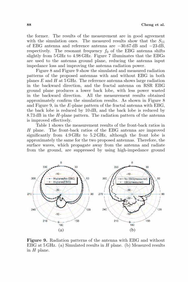
Figure 8 and Figure 9 show the simulated and measured radiationpatterns of the proposed antennas with and without EBG in bothplanes E and H at 5 GHz. The reference antenna shows large radiationin the backward direction, and the fractal antenna on RSR EBGground plane produces a lower back lobe, with less power wastedin the backward direction. All the measurement results obtainedapproximately confirm the simulation results. As shown in Figure 8and Figure 9, in the E-plane pattern of the fractal antenna with EBG,the back lobe is reduced by 10 dB, and the back lobe is reduced by8.73 dB in the H-plane pattern. The radiation pattern of the antennais improved effectively.
Table 1 shows the measurement results of the front-back ratios inH plane. The front-back ratios of the EBG antenna are improvedsignificantly from 4.9 GHz to 5.2 GHz, although the front lobe isapproximately the same for the two proposed antennas. Therefore, thesurface waves, which propagate away from the antenna and radiatefrom the ground, are suppressed by using high-impedance ground
(a) (b)
Figure 9. Radiation patterns of the antenna with EBG and withoutEBG at 5 GHz. (a) Simulated results in H plane. (b) Measured resultsin H plane.

Progress In Electromagnetics Research C, Vol. 11, 2009 89
planes, and the radiation pattern of the antenna is improved greatly.
Table 1. Measurement results of the proposed antennas with andwithout EBG in H plane.
Frequency (GHz)Front-back Ratio (dB)
Improved (dB)EBG No EBG
4.9 23.349 24.276 5.6925.0 17.657 18.802 8.7275.1 26.953 29.4563 5.4745.2 18.226 19.803 9.6263
4. CONCLUSIONS
This paper designs novel electromagnetic band-gap RSR EBGs. Thesize of EBG cell is reduced by introducing double reverse split rings intothe square patch. The bandgap bandwidth achieves about 65%. Usingthe EBGs as the ground plane of a fractal microstrip antenna, thesurface waves are suppressed effectively. Compared with the referenceantenna at 5GHz, an approximately 8 dB improvement of the returnloss is achieved, and the back lobe is reduced by 10 dB in E planeand 8.73 dB in H plane, respectively. The front-back ratios of theEBG antenna are improved significantly from 4.9 GHz to 5.2 GHz.Therefore, the performances of the antenna are improved greatly. Thenovel EBGs with wide bandwidth can be used in the microstrip antennadesign.
REFERENCES
1. Yablonovitch, E., “Photonic band-gap structure,” J. Opt. Soc.Am. B: Opt. Phys., Vol. 10, 283–295, 1993.
2. Radisic, V., Y. Qian, R. Coccioli, and T. Itoh, “Novel 2-D photonic bandgap structure for microstrip lines,” IEEETransactions on Microwave and Guided Wave Letters, Vol. 8,No. 2, 69–71, 1998.
3. Fan, Y. and Y. Rahmat-Samii, “Reflection phase characterizationsof the EBG ground plane for low profile wire antennaapplications,” IEEE Transactions on Antennas and Propagation,Vol. 51, No. 10, 2691–2703, 2003.
4. Coccioli, R., W. R. Deal, and T. Itoh, “Radiation characteristicsof a patch antenna on a thin PBG substrate,” IEEE Transactions

90 Cheng et al.
on Antennas and Propagation Society International Symposium,1998, Vol. 2, 656–659, 1998.
5. Dan, Q. and L. Shafai, “The performance of microstrippatch antennas over high impedance EBG substrates withinand outside its bandgap,” IEEE International Symposium onMicrowave Antenn, Propagation and EMC Technologies forWireless Communications, 2005. MAPE 2005, 423–426, 2005.
6. Qi, L., H. M. Salgado, A. M. Moura, and J. R. Pereira, “Dual-band antenna design using an EBG artificial magnetic conductorground plane,” IEEE Transactions on Antennas and PropagationConference, 2008. LAPC 2008. Loughborough, 217–220, 2008.
7. Sievenpiper, D., Z. Lijun, R. F. J. Broas, N. G. Alexopolous, andE. Yablonovitch, “High-impedance electromagnetic surfaces witha forbidden frequency band,” IEEE Transactions on MicrowaveTheory and Techniques, Vol. 47, No. 11, 2059–2074, 1999.
8. Coccioli, R., F.-R. Yang, K.-P. Ma, and T. Itoh, “Aperture-coupled patch antenna on UC-PBG substrate,” IEEE Transac-tions on Microwave Theory and Techniques, Vol. 47, 2123–2130,1999.
9. Li, Y., M. Fan, F. Chen, J. She, and Z. Feng, “A novel compactelectromagnetic-bandgap (EBG) structure and its applications formicrowave circuits,” IEEE Transactions on Microwave Theoryand Techniques, Vol. 53, 183–190, 2005.
10. Zheng, Q.-R., B.-Q. Lin, Y.-Q. Fu, and N.-C. Yuan, “Character-istics and applications of a novel compact spiral electromagneticband-gap (EBG) structure,” Journal of Electromagnetic Wavesand Applications, Vol. 21, No. 2, 199–213, 2007.
11. Sievenpiper, D., “High-impedance electromagnetic surfaces,”Ph.D. Dissertation, Department of Electrical Engineering,University of California at Los Angeles, CA, 1999.
12. McVay, J. and N. Engheta, “High impedance metamaterialsurfaces using Hilbert-curve inclusions,” IEEE Microw. WirelessCo. Lett., Vol. 14, No. 3, 130–132, 2004.
13. Fan, R. H. M. Y., Z. H. Feng, and X. X. Zhang, “Advance in2D-EBG research,” J. Infrared Millimeter Waves, Vol. 22, No. 2,2003.