Embed Size (px)
Citation preview

Design of a Near-Infrared Device for the Study of
Glucose Concentration Measurements
By
Dino Sia
Electrical and Biomedical Engineering Design Project (4BI6)
Department of Electrical and Computer Engineering
McMaster University
Hamilton, Ontario, Canada

Design of a Near-Infrared Device for the Study of
Glucose Concentration Measurements
By
Dino Sia
Electrical and Biomedical Engineering
Faculty Advisor: Prof. Howlader
Electrical and Biomedical Engineering Project Report
submitted in partial fulfillment of the degree of
Bachelor of Engineering
McMaster University
Hamilton, Ontario, Canada
April 2010
Copyright © April 2010 by Dino Sia

Abstract
Maintaining healthy blood glucose concentration levels is advantageous
for the prevention of diabetes and obesity. Present day technologies limit such
monitoring to patients who already have diabetes. The purpose of this project is
to suggest a non-invasive method for measuring blood glucose concentration
levels. Such a method would provide useful for even people without illness,
addressing preventive care. This project implements near-infrared light of
wavelengths 1450nm and 2050nm through the use of light emitting diodes and
measures transmittance through solutions of distilled water and d-glucose of
concentrations 50mg/dL, 100mg/dL, 150mg/dL, and 200mg/dL by using an
InGaAs photodiode. Regression analysis is done. Transmittance results were
observed when using near-infrared light of wavelength 1450nm. As glucose
concentration increases, output voltage from the photodiode also increases. The
relation observed was linear. No significant transmittance results were obtained
with the use of 2050nm infrared light due to high absorbance and low power. The
use of 1450nm infrared light provides a means of measuring glucose
concentration levels.
Keywords: Light emitting diode, glucose, blood, photodiode, photodetector,
transmittance, spectroscopy

Acknowledgements
I would like to thank my advisors Dr. Matiar Howlader and Dr. Thomas E.
Doyle for their guidance and help with this project. Also, I would like to thank
Saba Mohtashami, Fangfang Zhang, and M.G. Kibria for their advice and help
with the project and getting me started. I would also like to thank my family for
supporting me daily but especially throughout my education and this project.
Thank you to my brother who always finds a way to cheer me up.
Dino Sia

Contents
Abstract ……………………………………………………………... ii
Acknowledgements ………………………………………………… iii
Table of Contents …………………………………………………... iv
List of Tables ………………………………………………………. vi
List of Figures ……………………………………………………... vii
Nomenclature ……………………………………………………... viii
1 Introduction
1.1 Background ………………………………………………………….. 1
1.2 Objectives …………………………………………………………… 3
1.3 General Approach to the Problem …………………………………... 4
1.4 Scope of the Project …………………………………………………. 5
2 Literature Review
2.1 Glucose Properties ………………………………………………. 6
2.2 Reflectance versus Transmittance ………………………………... 7
3 Experimental or Design Procedures
3.1 Statement of Problem ……………………………………………...… 9
3.2 Methodology of Solution ……………………………………………. 9
3.3 Design Considerations …………………………………………. 10
3.4 Parts …………………………………………………………... 11
3.5 Theoretical & Initial Design ……………………………………. 12
3.6 Workflow Design ……………………………………………… 18
3.7 Testing & Design Refinements .…………………………...……. 19
3.8 Data Analysis ………………………..……………………….. 21

4 Results and Discussion
4.1 Introduction ………………………………………………………… 22
4.2 Initial Design ……………………………………………………….. 22
4.3 Refined Design ……………………………………………………... 24
4.4 Refinement of LED2050P Operation ………………………………. 27
4.5 Data Analysis ………………………………………………………. 29
4.6 Errors and Possible Areas Improvement …………………………… 32
5 Conclusions and Recommendations
5.1 Implementation Summary ………………………………………….. 34
5.2 Conclusions ………………………………………………………… 34
5.3 Recommendations ………………………………………………….. 35
5.4 Final Conclusion …………………………………………………… 36
Appendix A: Regression Analysis …………………...………………………… 37
Appendix B: Components List & Software ……………………………………. 39
Appendix C: Microcontroller Program ………………………………………… 40
Appendix D: MATLAB Code for Regression Analysis ……………………….. 42
References 43
Vitae 45
List of Tables
Table 2.1.1 Glucose absorption bands summarized according to the stretch &
vibrations of the bonds in the molecule …………………………………….…… 6
Table 3.3.1 Photodiode Material and Corresponding Electromagnetic Spectrum
Wavelength Range …………………………………………………………...… 11
Table 4.3.1 Photodiode Voltages for Various Glucose Concentrations ……….. 25
List of Figures
Figure 1.3.1 Schematic Overview of Operation of Non-Invasive Blood Glucose
Monitor. ……………………………………………………………………….… 4
Figure 2.1.1 Absorbance Spectrum of Glucose ……………………………….… 7
Figure 2.2.1 Transmittance versus reflectance ……………………….………… 8
Figure 3.5.1 Circuit for Biasing LED1450E …………………………………… 13
Figure 3.5.2 Circuit for Biasing LED2050P ……………………………...……. 14
Figure 3.5.3 Photodiode Responsivity …………………………………………. 15
Figure 3.5.4 Recommended Circuit Diagram ……………………………….…. 15
Figure 3.5.5 Voltage Divider Circuit ……………………………….………….. 16
Figure 3.5.6 Non-Inverting Amplifier …………………………………………. 17
Figure 3.6.1 Workflow Schematic of the System ………………………..…….. 18
Figure 3.7.1 Refined Photodiode and Amplifier Circuit ………………..……… 20
Figure 4.2.1 Initial Projected Functional Design …………………………….… 22
Figure 4.3.1 Functional Design using Test Tubes …………………………...… 24
Figure 4.3.2 Glucose Concentration versus Voltage from Photodiode ………... 25
Figure 4.3.3 Glucose Concentration vs. Maximum Voltage from Photodiode ... 26
Figure 4.4.1 50% Duty Cycle Current Used for LED2050P Operation Resulting in
1.1mW Power. …………………………………………………… 27
Figure 4.4.2 Pulsed Current Used for LED2050P Operation Resulting in 28mW
Power. ……………………………………………………………. 27
Figure 4.4.3 LED2050P Circuit Design Resulting in I=2A ………...………….. 28
Figure 4.5.1 Glucose Concentration vs. Minimum and Maximum Voltages ..… 30
Figure 4.5.2 Glucose Concentration Regression Model & Data Points ……..… 31
Figure 4.5.3 Robust and Least Squares Model ………………………………… 31
Nomenclature
The following are words used through the report. Their definitions are given.
Absorbance: the ability of a layer of a substance to absorb radiation
Concentration: the amount of component in a given volume
Glucose: a crystalline sugar C6H12O6.
LED: Acronym for Light Emitting Diode.
MATLAB: Software used for mathematical calculations.
Microcontroller: small computer on a single integrated circuit
Photodiode: A semiconductor sensor used to detect light. Depending upon
incident light intensity, current is produced.
Power: the rate at which work is performed or energy is converted
Transmittance: the fraction of radiant energy that having entered a layer of
absorbing matter reaches its farther boundary
Wavelength: the distance in the line of advance of a wave from any one point to
the next point of corresponding phase

Chapter 1
Introduction
1.1 Background
The continual increase in global population in addition to the expected
increases in global obesity and diabetes – more so in North America - suggests
that there may also need to be an increase in doctors or health practitioners. In
Canada, as of 2007 there were 2.18 doctors per 1,000 people, which although has
increased from previous years it is still less other leading industrialized countries
[1]. Because health care practice is a highly specialized profession that requires
many years of study, such an increase in the number of physicians to
accommodate patients may not be easily feasible.
In health care, there are many various instrumentation devices that
diagnose patients. These diagnostic devices allow for better implementation of
corrective or supportive medical devices and methods of dealing with a wide
variety of diseases and disabilities. However, the increasing global population
and the poor ratio of doctors per capita, especially in North America, brings forth
the concern of being able to provide corrective or supportive methods of treatment
for ailments for all of the population.
Such diagnostic, corrective, and supportive devices are widely used
throughout health care practice in hospitals, clinics, and even in homes. Their
functionality and importance has assisted practicing physicians, therapists,
specialists and nurses with daily routine work. However, since a large majority of
these instrumentation devices are corrective and supportive, they are used on
patients who already suffer from illnesses. This does not necessarily translate to
lowered mortality due to illness, nor does it result in a reduced likelihood of
developing illness. Because of the high costs, limited availability, and often the
requirement of professional and qualified assistance, such instrumentation devices
may not be accessible to all patients. This brings about the importance of
preventive care as a means to reduce the likelihood of disease and illness.
In 2004, diabetes contributed 18.4 deaths per 100,000 people in Canada
and 20.2 deaths per 100,000 in the United States of America [1]. In 2007, 46.8%
of Canadians were reported as either overweight or obese while a staggering
67.3% of Americans were reported as either overweight or obese in 2006 [1].
Instead of spending money on medications or methods to reduce obesity or to
cope with the effects of diabetes, perhaps if the focus was on preventing people
from becoming diabetic, obese, or both, a lot less money would need to be spent
on such health-related issues. Not only could such preventive reduce the amount
of people who are obese or have diabetes, but could also benefit health care its
allocation of expenses. It may result in more patients per doctor.
Engineering involves the development of products that benefit society.
Biomedical engineering focuses on products or devices that are most widely used
in health care with a purpose of providing efficient and accurate patient diagnoses
and care. The purpose of this engineering project was to address the idea of
preventive care as oppose to corrective or supportive care. The goal was to
provide suggestion for a device that could possibly be recommended within the
health care community that allows patients to monitor their health preventing
them from overeating or avoiding high sugar foods. This may perhaps aid in
preventing diabetes or obesity and thus improving their quality of life.
The project investigates a possible method of measuring glucose
concentrations through the use of near-infrared light by emission from light
emitting diodes. The project aims to find a relation between the absorption of
near-infrared light and various glucose concentrations. This is a non-invasive

method of measuring glucose concentrations may become a more popular choice
for diabetics and in being non-invasive its uses may extend to the general public.
In having a large majority of populations able to monitor their blood glucose
levels, it may prevent hyperglycemia, hypoglycemia, and perhaps the onset of
diabetes.
1.2 Objectives
The objective of this project is to provide a non-invasive approach to
measuring and thus monitoring blood glucose concentration levels. As oppose to
the current minimally invasive and painful methods of measuring blood glucose
concentrations, a non invasive method provides as excellent and perhaps more
desirable alternative to present day technologies. To develop such a non-invasive
glucose concentration measurement instrumentation device, near-infrared light
and its absorption depending on various glucose concentrations will be examined.
The use of near-infrared light to measure glucose concentrations does not involve
using a lancet to obtain blood samples. Much like how pulse-oximetry is
generally used on fingers, a similar approach in measuring blood glucose
concentrations from fingers would be easy and more convenient as oppose to
taking measurements from other body parts.
An easy and pain-free method of measuring blood glucose concentrations
will give people information needed that may help them develop proper or better
eating habits and it may allow monitoring to provide information for doctors and
physicians to better diagnose patients if any ailments arise. If people eat healthier
and exercise more – perhaps as a response to constant high blood glucose
concentration readings – the prevalence or possibility of developing diabetes or
being obese may lessen. This in turn could lead to lesser doctor visits which may
promote a higher doctor per capita ratio. It may also lead to reduced waiting
times in hospitals or doctor offices. Deaths due to obesity or diabetes may
decrease, but more importantly the quality of life of the general population may

increase. There are many possible positive outcomes from the simple use of
blood glucose concentration monitoring among the mass population. There are
many corrective or supportive care devices and methods. Preventive care
however should not be overseen and perhaps should be a more prioritized focus.
A non-invasive blood glucose concentration monitor seeks to address a method of
preventive care.
1.3 General Approach
In order to measure blood glucose concentrations, the instrumentation
device involves the emission of near-infrared light and detecting an absorbance of
the light after it has passed through a specific glucose concentration. A general
schematic can be seen in Figure 1.3.1.
Figure 1.3.1 Schematic Overview of Operation of Non-Invasive Blood Glucose
Monitor. NIR are Near-Infrared Emitting Light Sources, Detector detects the
amount of light.

In order to implement such an instrumentation device, the chemical and
physical properties of glucose in addition to its absorbance at specific
wavelengths were examined. In order for the operation of the near-infrared light
sources and light detector as well as the analysis of the data, specific compatible
hardware and software choices need to be made. Such choices for hardware and
software are given in chapter 3.
1.4 Scope of the Project
This project involves the use of near-infrared light and transmittance
spectroscopy for the use of measuring glucose concentration levels. Data analysis
will be done so as to create a model to best predict glucose concentration levels
based on transmittance.
Chapter 2
Literature Review
2.1 Glucose Properties
In order to develop an instrumentation device that is accurate and specific
to glucose and its concentrations, the chemical and physical properties of glucose
need to be examined. Research papers regarding glucose‟s reflectance or
absorbance at various wavelengths will examined. One research paper [2]
examined the prediction of glucose concentrations by near-infrared diffuse
reflectance spectroscopy between the wavelengths 1050nm to 2450nm, and
determined that with calibration models developed through partial least squares
regression, such a method is viable to predict blood glucose concentrations non-
invasively.
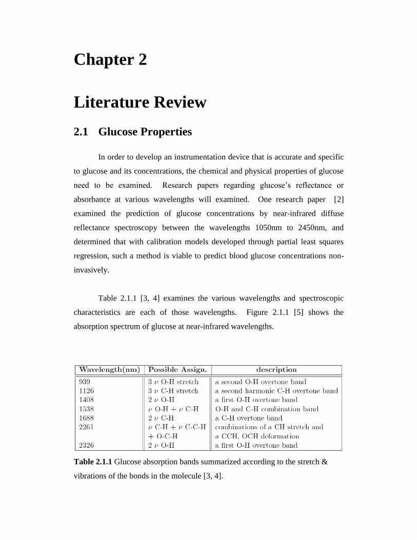
Table 2.1.1 [3, 4] examines the various wavelengths and spectroscopic
characteristics are each of those wavelengths. Figure 2.1.1 [5] shows the
absorption spectrum of glucose at near-infrared wavelengths.
Table 2.1.1 Glucose absorption bands summarized according to the stretch &
vibrations of the bonds in the molecule [3, 4].

Figure 2.1.1 Absorbance Spectrum of Glucose [5].
Given the above spectrum and absorbance information, a research paper
[6] compared the accuracies of different wavelength regions as a means to predict
glucose concentration levels – the overtone (1100 to 1850nm) and combination
(2050 to 2392nm) bands. These specific regions were chosen because the
overtone band contains an absorption peak at 1688nm originated 2v of –CH and
the combination band has peaks that are combinations of a CH stretch and CCH,
OCH deformation [3]. The research paper [6] suggests glucose spectroscopy
between wavelengths 1100nm to 2450nm is a possible method of analyzing and
predicting glucose concentrations.
2.2 Transmittance versus Reflectance
Glucose determination using near-infrared spectroscopy can be done by
taking measurements of either transmittance or reflectance. Transmittance
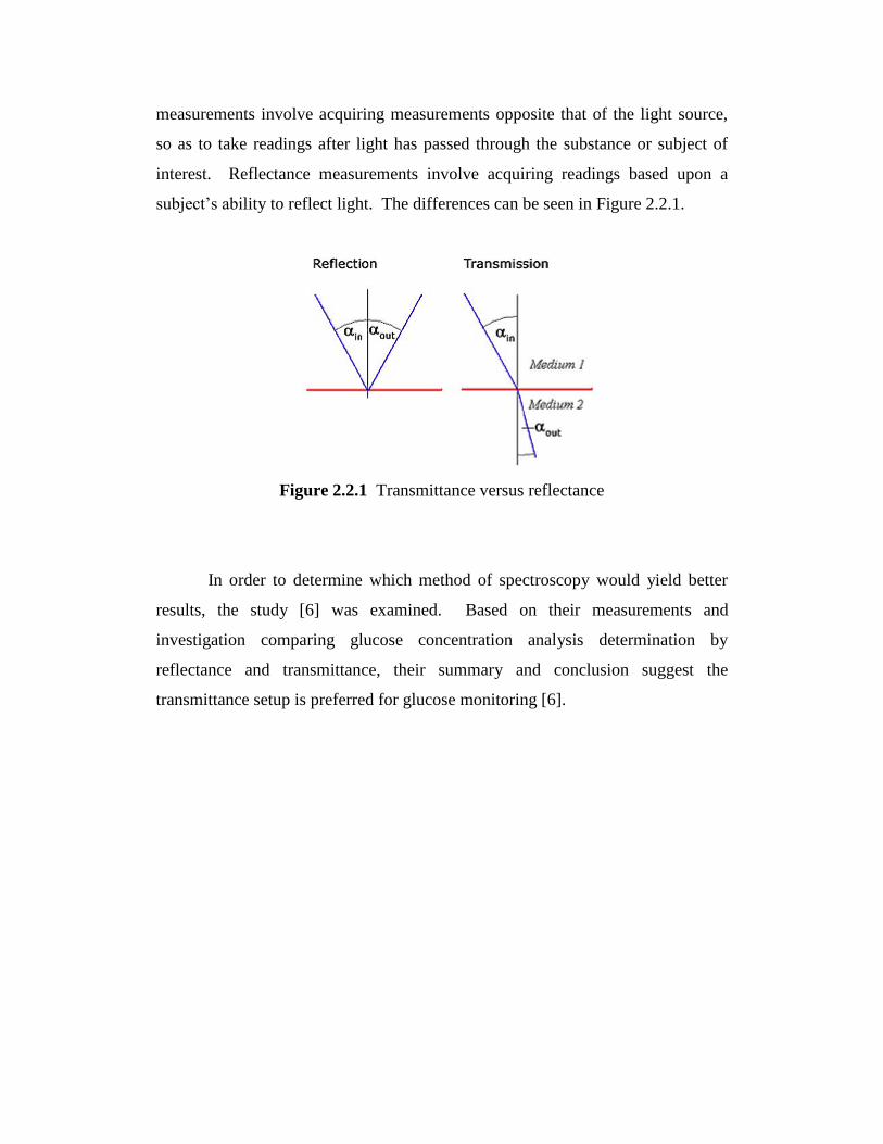
measurements involve acquiring measurements opposite that of the light source,
so as to take readings after light has passed through the substance or subject of
interest. Reflectance measurements involve acquiring readings based upon a
subject‟s ability to reflect light. The differences can be seen in Figure 2.2.1.
Figure 2.2.1 Transmittance versus reflectance
In order to determine which method of spectroscopy would yield better
results, the study [6] was examined. Based on their measurements and
investigation comparing glucose concentration analysis determination by
reflectance and transmittance, their summary and conclusion suggest the
transmittance setup is preferred for glucose monitoring [6].
Chapter 3
Experimental or Design Procedures
3.1 Statement of Problem
Current day technologies for measuring blood glucose concentration levels
are minimally invasive requiring a sample of blood in order to obtain a reading.
This is often painful for the user and such means to measure blood glucose
concentration levels are likely undesired. Additionally, because they require test
strips that are costly for each measurement, they may not be easily obtainable for
patients. The next problem involves the patients who use it. Non-diabetics have
no want or no need to use them. However, with poor eating habits and lack of
health monitoring, the onset of diabetes or obesity is more prevalent. It is
suggested that if even people who are not ill continuously monitor their health,
they may be less likely to succumb to illness in the future. This brings about the
need for preventive health measures.
3.2 Methodology of Solution
The objective is to develop a non-invasive method for measuring blood
glucose concentration levels. Such a method would be pain-free and therefore
possibly more desirable amongst a larger population for use with continuous
health monitoring. The solution would be using near-infrared light to measure
blood glucose concentration levels. Such a method would be painless and would
not require tedious amounts of test strips for each measurement. Because it would
be painless, it may easily be recommended and used by the general population to
monitor their day-to-day health to best adjust their eating habits or exercise.

3.3 Design Considerations
In designing the system, methods of near-infrared light emission and
detection were explored. As suggested by [6], transmission spectroscopy for
measuring glucose concentrations is favoured over reflectance. According to [2],
[5], [6], [7], near-infrared wavelengths in the ranges of 1100 to 1850nm and 2050
to 2392nm are suitable for measuring glucose concentrations by absorbance.
Thus, sources of light emission in the ranges of 1100 to 1850nm and 2050 to
2392nm were needed.
Without access to a spectrometer that analyzes light of wavelengths in the
near-infrared spectrum, another option was needed. This brings about the use of
photodiodes. Photodiodes are photodetectors that convert light into current of
voltage. Materials used in photodiodes are what determine its properties, most
specifically the range of wavelengths of the electromagnetic spectrum the
photodiode is capable of outputting a voltage or current. Table 3.3.1 compares 4
different photodiode materials and their respective electromagnetic spectrum
wavelength sensitivity. From Table 3.3.1, possible options are photodiodes of
indium gallium arsenide or lead (II) sulfide.

Material Electromagnetic Spectrum
wavelength range (nm)
Silicon 190-1100
Germanium 400-1700
Indium gallium arsenide 800-2600
Lead(II) sulfide <1000-3500
Table 3.3.1 Photodiode Material and Corresponding Electromagnetic Spectrum
Wavelength Range [8].
3.4 Parts
Given the requirements of a light source in the range of 1100 to 1850nm
closer to 1688nm, a light emitting diode (LED) by ThorLabs (LED1450E) that
emits near-infrared light at 1450nm was chosen. Given the requirements of a
light source in the range of 2050 to 2392nm preferentially closer to 2261nm, an
LED by Thorlabs (LED2050P) that emits near-infrared light at 2050nm was
chosen.
The photodiode chosen was the ThorLabs FGA20 as it has an
electromagnetic wavelength response range of 1200nm to 2600nm, thus only one
photodiode would be needed to obtain measurements from the two LEDs of
different wavelengths. The maximum output voltage of the photodiode is 1 volt.
In order to bias the various diodes and obtain voltage measurements from
the photodiode, the use of a microcontroller would be very appropriate. A very
user friendly and easy to code microcontroller was chosen – the Arduino
Duemilanove. It has a maximum output voltage of 5V. It has a maximum input
voltage of 5 volts with a built-in analog-to-digital converter with an accuracy of
1024 bits – thus 0.0049 volts per bit. Because the maximum output voltage of the
photodiode is 1V and the maximum input to the microcontroller is 5V, a non-
inverting amplifier was implemented. The operational amplifier OP491 was
chosen. Additionally, various resistors were used.
3.5 Theoretical & Initial Design
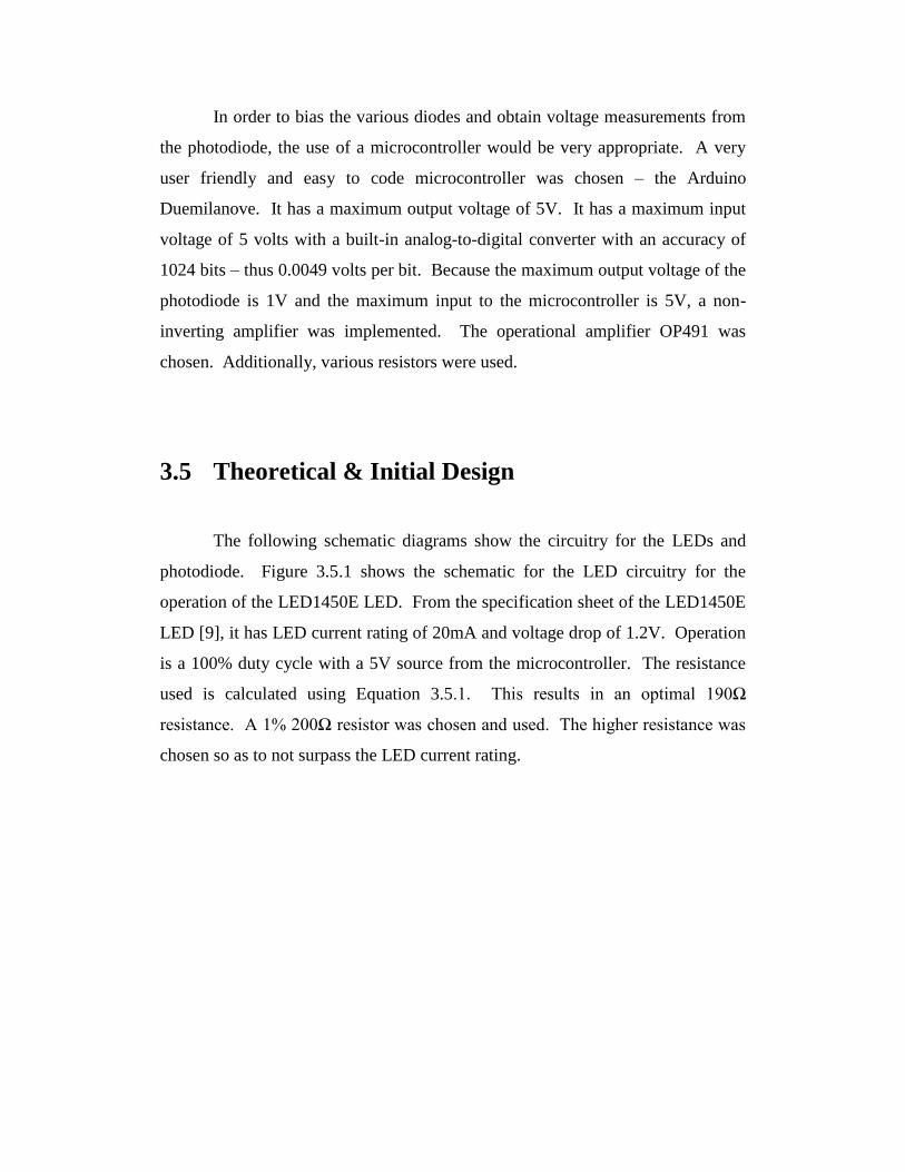
The following schematic diagrams show the circuitry for the LEDs and
photodiode. Figure 3.5.1 shows the schematic for the LED circuitry for the
operation of the LED1450E LED. From the specification sheet of the LED1450E
LED [9], it has LED current rating of 20mA and voltage drop of 1.2V. Operation
is a 100% duty cycle with a 5V source from the microcontroller. The resistance
used is calculated using Equation 3.5.1. This results in an optimal 190Ω
resistance. A 1% 200Ω resistor was chosen and used. The higher resistance was
chosen so as to not surpass the LED current rating.
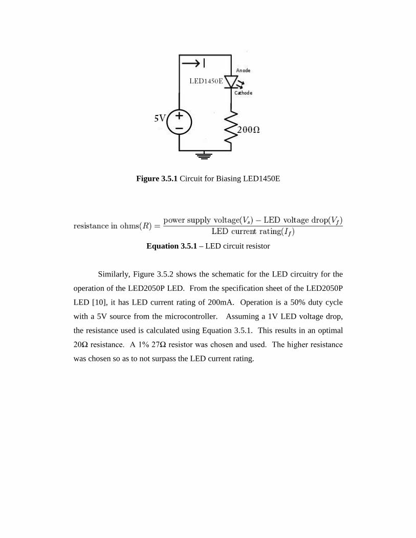
Figure 3.5.1 Circuit for Biasing LED1450E
Equation 3.5.1 – LED circuit resistor
Similarly, Figure 3.5.2 shows the schematic for the LED circuitry for the
operation of the LED2050P LED. From the specification sheet of the LED2050P
LED [10], it has LED current rating of 200mA. Operation is a 50% duty cycle
with a 5V source from the microcontroller. Assuming a 1V LED voltage drop,
the resistance used is calculated using Equation 3.5.1. This results in an optimal
20Ω resistance. A 1% 27Ω resistor was chosen and used. The higher resistance
was chosen so as to not surpass the LED current rating.
Figure 3.5.2 Circuit for Biasing LED2050P
The specifications sheet of the ThorLabs FGA20 [11] provides Equation
3.5.2 and Equation 3.5.3. The photodiode electromagnetic wavelength
responsivity can be seen in Figure 3.5.3 [11] which has also been given by the
specification sheet of the photodiode.
Vo = P x R(λ) x RL
Equation 3.5.2 – Output Voltage of Photodiode
Where: P is the incident light power at a given wavelength λ
R(λ) is the responsivity given by Equation 3.5.3 (which can be read
from Figure 3.5.3)
RL is the load resistor whose placement is shown in Figure 3.3.4
R(λ) = Ip / P
Equation 3.5.3 – Responsivity of Photodiode
Where: Ip is the photocurrent at a given wavelength
P is the light power at a given wavelength

Figure 3.5.3 Photodiode Responsivity
Figure 3.5.4 Recommended Circuit Diagram

From the specification sheets of both LED [9, 10] and the photodiode [11],
the resistance load RL for the suggested photodiode circuit can be calculated.
First, calculations were done to calculate RL using the 1450nm LED. With a
power of 2.0mW or 0.002W, a responsivity of 0.6 A/W (as given by Figure 3.5.3
at 1450nm), and Vo of 1V, the calculated RL is RL = 833Ω. Then, calculations
were done to calculate RL using the 2050nm LED. With a power of 1.1mW or
0.0011W, a responsivity of 1.2 A/W (as given by Figure 3.5.3 at 2050nm), and Vo
of 1V, the calculated RL is RL = 757Ω. Comparing both required RL‟s, the lower
value of RL = 757Ω was chosen and thus RL = 780Ω (200Ω + 200Ω +200Ω +
180Ω) was used.
Since the maximum output voltage of the microcontroller is 5V and the
recommended bias voltage of the photodiode is 1V, a voltage divider circuit was
used (Figure 3.5.5). The following calculations were done using Equation 3.5.4.
Since Vout = 1V and Vin = 5V, resistors were chosen as R1= 200Ω and R2 = 51Ω.
Figure 3.5.5 Voltage Divider Circuit
Vout = Vin [ R2 / (R1 + R2) ]
Equation 3.5.4 Vout of a Voltage Divider Circuit

Since the maximum input voltage of the microcontroller, the Arduino
Duemilanove, is 5V, a non-inverting amplifier was used. Figure 3.5.6 shows the
schematic of a non-inverting amplifier. In a non-inverting amplifier, Vout is
given by Equation 3.5.5. Assuming a maximum input voltage of 1V and a desired
output voltage of 5V, R2 / R1 was selected such that (1 + R2 / R1) = 5. R2 was
chosen as R2 = 200Ω and R1 was chosen as R1 = 51Ω.
Figure 3.5.6 Non-Inverting Amplifier
Vout = Vin (1 + R2 / R1)
Equation 3.5.5 Vout of a Non-Inverting Amplifier
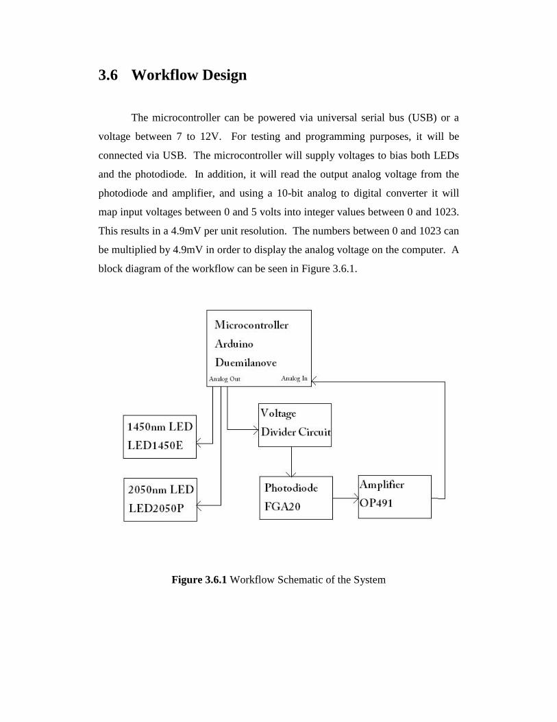
3.6 Workflow Design
The microcontroller can be powered via universal serial bus (USB) or a
voltage between 7 to 12V. For testing and programming purposes, it will be
connected via USB. The microcontroller will supply voltages to bias both LEDs
and the photodiode. In addition, it will read the output analog voltage from the
photodiode and amplifier, and using a 10-bit analog to digital converter it will
map input voltages between 0 and 5 volts into integer values between 0 and 1023.
This results in a 4.9mV per unit resolution. The numbers between 0 and 1023 can
be multiplied by 4.9mV in order to display the analog voltage on the computer. A
block diagram of the workflow can be seen in Figure 3.6.1.
Figure 3.6.1 Workflow Schematic of the System

3.7 Testing & Design Refinements
The goal was also to use parts that are relatively cheap and easily
accessible so as provide an affordable solution or alternative to invasive blood
glucose testing. Such limitations resulted in the implementation using of LEDs as
oppose to perhaps lasers with higher power and a photodiode as oppose to a very
expensive spectrometer. The initial idea was to have near-infrared light pass
through a thin, easily accessible and convenient part of the body such as the
finger.
The microcontroller was programmed to output 5V 100% duty cycles for
biasing the LED1450E and FGA20. It was programmed to output 5V at a 50%
duty cycle for the LED2050P. The output of the non-inverting amplifier was
connected to the analog-in of the microcontroller. The integer value that resulted
from the analog-to-digital conversion was multiplied by 4.9 and that resulting
output was shown on the computer screen. A multimeter Equus #4320 was used
to measure various voltages and currents. The current across the LEDs were
within specification and the voltage measurements suggested the LEDs were on.
To further determine if the near-infrared LEDs were emitting light, the
photodiode was required. By moving the LEDs to emit their light onto the 1mm2
area of the photodiode, the measured output voltage of the photodiode increased.
This showed the functionality of the LED1450E and LED2050P LEDs and the
FGA20 photodiode.
However, the maximum 5V output after the amplifier was not obtained.
The gains and RL were then modified so as to obtain the maximum 5V voltage.
First, the RL value (as seen in Figure 3.5.4) was adjusted to achieve an output
voltage as close to 1V as possible. This eventually led to the use of RL = 50kΩ.
Next, the gain resistors of the non-inverting amplification stage were adjusted
such that Vout (as in Figure 3.5.5) was as close to 5V as possible. This eventually

led to the use of R1 = 100kΩ and R2 = 3.9kΩ. Such changes however resulted in a
greater resting voltage of 1.5V as Vout from the amplifier. The following
refinements are shown in Figure 3.7.1.
Figure 3.7.1 Refined Photodiode and Amplifier Circuit
Next, testing was done by emitting light through the index finger and trying to
obtain a voltage increase output of the photodiode. Regardless of which LED was
used, the output voltage of the photodiode did not change. For this reason, test
tubes were used and solutions of distilled water and d-glucose were formulated
and used for measurement. While voltage increases were found for the LED
emitting near-infrared light at 1450nm, no voltage increases were found for the
LED emitting near-infrared light at 2050nm. Thus, in order to increase the power
of the LED to 28mW, a pulsed response duty cycle of 2A for 1µs every 499µs
was used. This involved changing the resistor in Figure 3.5.2 from 27Ω to 2Ω.

3.8 Data Analysis
The output voltage of the photodiode is expected to vary depending on the
wavelength of the near-infrared light and the concentration of glucose. Given
these various output voltages for the two used wavelengths 1450nm and 2050nm
and knowing blood glucose levels are lowest in the morning and highest
postprandial, partial least-squares regression analysis will be used to best
determine a relationship between output voltages and glucose concentrations. In
order to do so, MATLAB will be used and regression analysis will be done.
Further info on regression analysis can be found in Appendix A.
Chapter 4
Results and Discussion
4.1 Introduction
Results and measurements obtained from initial through final experimental
designs will be presented. There will be discussion regarding these results as well
as remedies or suggested remedies to problems encountered to lead to refinements
and the final design.
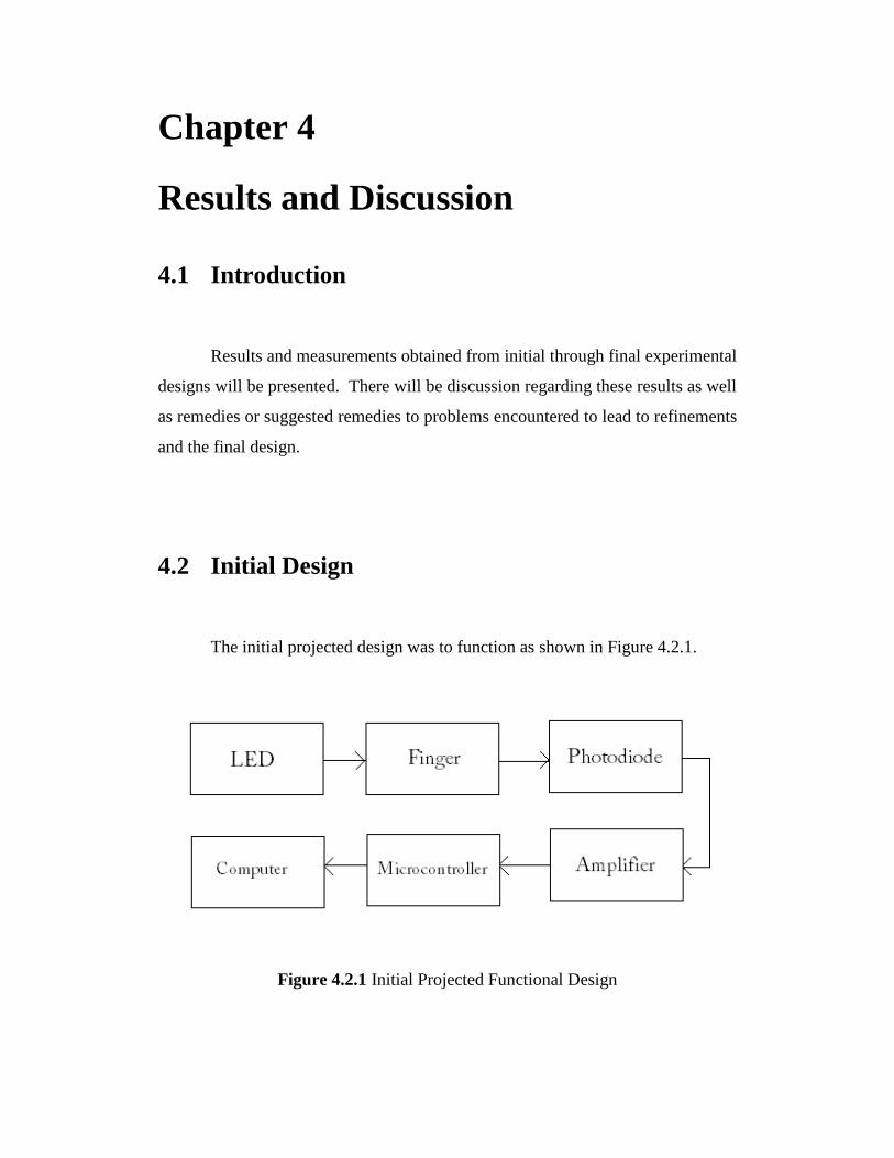
4.2 Initial Design
The initial projected design was to function as shown in Figure 4.2.1.
Figure 4.2.1 Initial Projected Functional Design

Without passing the near-infrared light from the LEDs through the finger,
this initial design provided voltage outputs between approximately 1500mV (zero
infrared light aimed towards the active area of the photodiode) to approximately
4900mV (maximum voltage obtained by aiming infrared light towards the active
area of the photodiode). However, with the introduction of the finger to the
system, the voltage outputs remained constant at approximately 1500mV without
any increase. This suggests that the power emitted by the LEDs is not enough to
penetrate the tissues of the finger. Further increasing the amplification of the
amplifier stage or increasing RL in the photodiode circuit resulted in further
increased minimum voltage but still zero increase in voltage with the introduction
of a finger to the system.
In order to obtain measurements from the system, the finger stage of
Figure 4.2.1 was replaced with various test tubes containing solutions of distilled
water and d-glucose with concentrations of 50mg/dL, 100mg/dL, 150mg/dL, and
200mg/dL. Such concentrations were chosen as they most closely represent the
various blood glucose concentration levels of humans, with 50 to 100 mg/dL
being low and average to high, and 150 or 200mg/dL being high and extremely
high.

4.3 Refined design
The redesigned functional design is shown in Figure 4.3.1.
Figure 4.3.1 Functional Design using Test Tubes
Testing was done with lights in the room turned off in order to eliminate
possible noise from nearby light sources. For each of the various glucose
concentrations contained in the test tubes, the test tube was held in a horizontal
position directly above the photodiode. First, the LED1450E was aligned on top
of the test tube so as to emit light through the test tube. The angle of the LED was
continuously adjusted so as to observe the highest possible voltage reading.
Voltage readings from the photodiode were observed. Next, the LED2050P was
aligned on top of the test tube so as to emit light through it. The angle of the LED
was continuously adjusted so as to observe the highest possible voltage reading.
Voltage readings from the photodiode were observed. The voltage readings from
each of the test tubes and concentrations are summarized in Table 4.3.1.

Concentration
of glucose
(mg/dL)
1450nm
Minimum
Voltage (mV)
1450nm
Maximum
Voltage (mV)
2050nm
Minimum
Voltage (mV)
2050nm
Maximum
Voltage (mV)
50 1616 1651 1548 1563
100 1616 1670 1548 1568
150 1646 1685 1548 1563
200 1680 1720 1548 1563
Table 4.3.1 Photodiode Voltages for Various Glucose Concentrations
Depending on the angle of the LED1450E, the voltage output from the
photodiode changed. However, the maximum voltage readings remained the
maximum regardless of trial number. This proves the results are repeatable.
However as can be seen from Figure 4.3.2 and Table 4.3.2, when comparing the
minimum and maximum values for the four tested concentrations there is an
overlap of resulting voltages.
1600 1620 1640 1660 1680 1700 17200
50
100
150
200
250
Voltage mV
Glu
cose C
oncentr
ation m
g/d
L
Figure 4.3.2 Glucose Concentration versus Voltage from Photodiode

However, when comparing only the maximum voltages it can be seen that
only one maximum voltage corresponds to one glucose concentration (Figure
4.3.3). The relationship appears to be linear – as the maximum voltage increases,
the concentration of glucose increases proportionally as well.
Figure 4.3.3 Glucose Concentration versus Maximum Voltage from Photodiode
When testing the glucose concentrations using the LED2050P, the
minimum and voltages for all concentrations were the same. Similarly, the
maximum voltages were the same except when testing with the glucose
concentration of 100mg/dL. It resulted in a 5mV reading higher than the other
concentrations. Because both higher and lower concentrations (50mg/dL,
150mg/dL, and 200mg/dL) yield the same results, the 5mV difference observed
by the 100mg/dL concentration can be neglected. Because there were no
significant voltage changes noted when using the LED2050P, further refinements
to its operation were implemented.

4.4 Refinement of LED2050P Operation
The lack of significant notable results when using the LED2050P as the
light source as a means to obtain a voltage from the photodiode depending on
various glucose concentrations brought forth the need possibly increase the LED‟s
power. Its initial operation of a 50% duty cycle with a 200mA current resulted in
light emission with a power of 1.1mW (Figure 4.4.1). By changing to a pulsed
duty cycle of 1µs on and 499µs off with a 2A current (Figure 4.4.2) theoretically
results in light emission with a power of 28mW. In order to implement such
changes, the resistor in Figure 3.5.2 was changed from 27Ω to 2Ω (Figure 4.4.3),
and the microcontroller was programmed to output voltage for 1µs of every
500µs. Testing on the various test tubes containing the glucose solutions was
repeated.
Figure 4.4.1 50% Duty Cycle Current Used for LED2050P Operation Resulting
in 1.1mW Power.

Figure 4.4.2 Pulsed Current Used for LED2050P Operation Resulting in 28mW
Power.
Figure 4.4.3 LED2050P Circuit Design Resulting in I=2A
Again, however, regardless of angle or location of the LED2050P, the
minimum and maximum output voltages from the photodiode were not significant
in comparison to the minimum voltages, with the minimum voltages being the
same for all concentrations. The minimum voltage was also the recorded voltage
without the use of an LED. Such results suggest that the absorbance of the
solution at 2050nm is high, the power of the LED is inadequate, or both. By
examining Figure 2.1.1 it can be seen that the absorption of glucose at 2050nm is
indeed higher than at 1450nm.
To confirm this, an empty test tube was used between the LED2050P and
photodiode FGA20. Output voltages from the photodiode were significantly
above the voltages without the LED. With the introduction of a glucose solution
even as low as 50mg/dL, output voltages result in the same voltage as that without
the LED. This confirms the premise that the absorbance of glucose is too high
and/or the power of the LED is inadequate.

4.5 Data Analysis
Due to the lack of significant results when using infrared light of
wavelength 2050nm, data analysis and observations will only be considered with
results obtained from using infrared light of wavelength 1450nm. Referring to
Table 4.3.1 and Figure 4.3.2, assuming glucose concentrations are not known, it
can be seen that between voltages 1616mV to 1651mV, the glucose concentration
could either be 50mg/dL or 100mg/dL. Between 1646mV and 1651mV the
concentration can be either 50mg/dL, 100mg/dL, or 150mg/dL. In the range of
1651mV to 1670mV the concentration is either 100mg/dL or 150mg/dL. In the
range of 1680mV to 1685mV the concentration is either 150mg/dL or 200mg/dL.
These overlapping results suggest that it would be difficult to predict glucose
concentrations.
With voltage readings of 1670mV to 1680mV there is only one glucose
concentration (150mg/dL). When the voltage readings exceed 1685mV, it is clear
that the concentration of glucose is 200mg/dL.
To further analyze the results, MATLAB was used. An implementation of
the function „regress‟ was used with the aid of the MATLAB statistics toolbox.
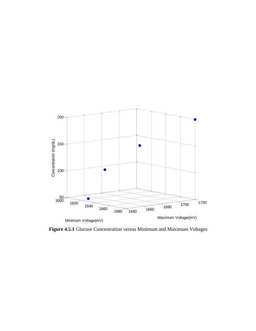
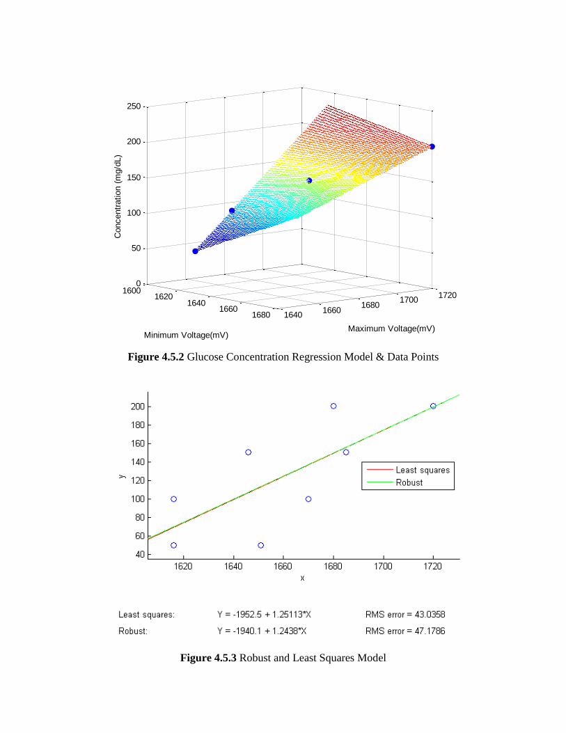
Additionally, „robustdemo‟ was used to develop a best fit model. Figure 4.5.1
shows a 3-dimensional plot of the glucose concentration based on the minimum
and maximum voltage readings. Figure 4.5.2 contains the plots of the observed
data points as well as a mesh to represent the multiple linear regression. Figure
4.5.3 is the results when using „robustdemo‟ with the given data points.
16001620
16401660
1680 16401660
16801700
1720
50
100
150
200
Maximum Voltage(mV)Minimum Voltage(mV)
Concentr
ation (
mg/d
L)
Figure 4.5.1 Glucose Concentration versus Minimum and Maximum Voltages
16001620
16401660
1680 16401660
16801700
1720
0
50
100
150
200
250
Maximum Voltage(mV)Minimum Voltage(mV)
Concentr
ation (
mg/d
L)
Figure 4.5.2 Glucose Concentration Regression Model & Data Points
Figure 4.5.3 Robust and Least Squares Model
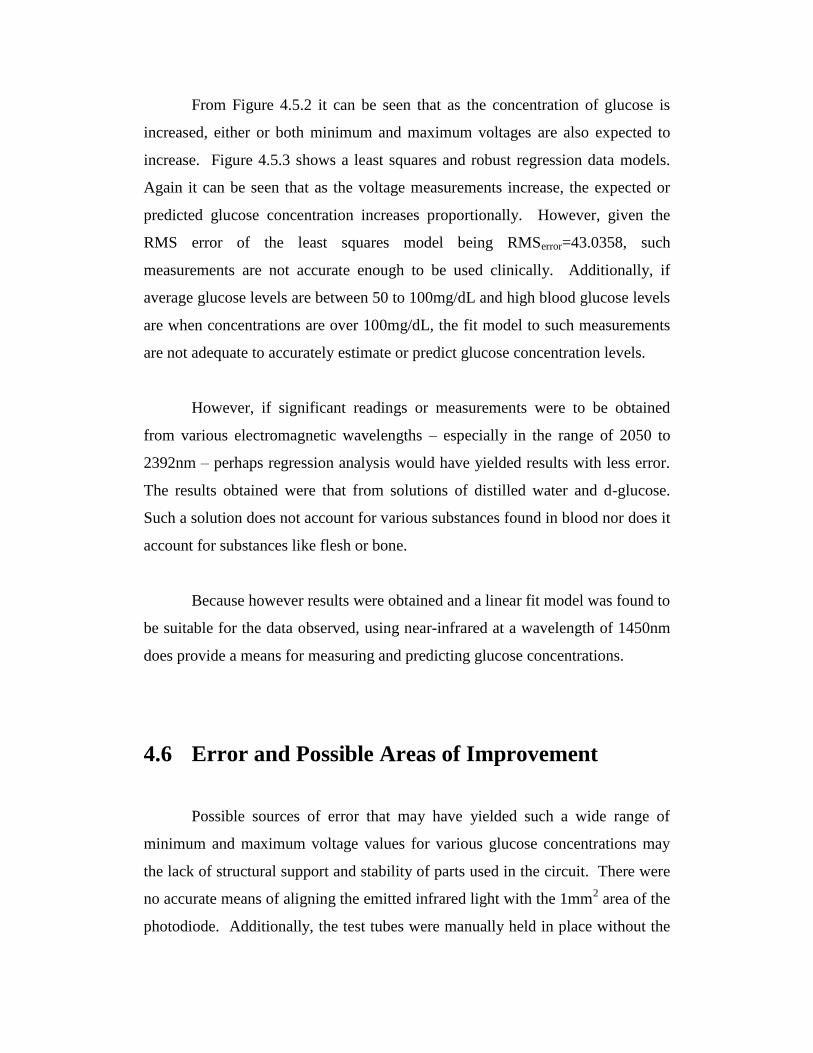
From Figure 4.5.2 it can be seen that as the concentration of glucose is
increased, either or both minimum and maximum voltages are also expected to
increase. Figure 4.5.3 shows a least squares and robust regression data models.
Again it can be seen that as the voltage measurements increase, the expected or
predicted glucose concentration increases proportionally. However, given the
RMS error of the least squares model being RMSerror=43.0358, such
measurements are not accurate enough to be used clinically. Additionally, if
average glucose levels are between 50 to 100mg/dL and high blood glucose levels
are when concentrations are over 100mg/dL, the fit model to such measurements
are not adequate to accurately estimate or predict glucose concentration levels.
However, if significant readings or measurements were to be obtained
from various electromagnetic wavelengths – especially in the range of 2050 to
2392nm – perhaps regression analysis would have yielded results with less error.
The results obtained were that from solutions of distilled water and d-glucose.
Such a solution does not account for various substances found in blood nor does it
account for substances like flesh or bone.
Because however results were obtained and a linear fit model was found to
be suitable for the data observed, using near-infrared at a wavelength of 1450nm
does provide a means for measuring and predicting glucose concentrations.
4.6 Error and Possible Areas of Improvement
Possible sources of error that may have yielded such a wide range of
minimum and maximum voltage values for various glucose concentrations may
the lack of structural support and stability of parts used in the circuit. There were
no accurate means of aligning the emitted infrared light with the 1mm2 area of the
photodiode. Additionally, the test tubes were manually held in place without the

aid of a stabilizing apparatus. To possibly obtain more accurate and precise
results, a stable attachment and proper aligning of the emitted infrared light and
active photodiode area could have been implemented.
The accuracy of the concentrations of glucose may also have contained
error. Preparations of solutions were done using an electronic scale with accuracy
to the nearest gram. Test tubes may also have provided sources of error as they
are rounded. The use of cuvettes may provide better results.
No readings were obtained from the LED emitting infrared light at
2050nm. Possible reasons may be too high of an absorbance or inadequate
power. To obtain better results, lasers at such wavelengths could be used.
However, lasers are much more expensive and inaccessible.

Chapter 5
Conclusion and Recommendations
5.1 Project Implementation Summary
The initial problem was the use of minimally invasive methods for blood
glucose concentration measurements. To address this problem, this project
observed using near-infrared as a possible means to measure blood glucose
concentrations. Such implementation would be non-invasive. To implement the
use of non-infrared, light emitting diodes that emit light at 1450nm and 2050nm
were chosen and used. To detect absorption a photodiode with an
electromagnetic sensitivity to electromagnetic light between wavelengths of
1200nm to 2600nm was used. To simulate blood glucose concentrations,
solutions of distilled water and d-glucose was used in a test tube. Concentrations
of 50mg/dL, 100mg/dL, 150mg/dL, and 200mg/dL were used. Regression
analysis was done on the data in order to find a model to best predict glucose
concentrations based on voltage readings from the photodiode.
5.2 Conclusions
Using near-infrared light of wavelength 2050nm, minimum photodiode
output voltages were the same for all solutions (1548mV). Maximum photodiode
output voltages were 1563mV for all concentrations except 100mg/dL which
resulted in a 1568mV maximum voltage. Because the minimum voltages were
the same for all solutions and 50mg/dL and 150mg/dL resulted in the same
maximum voltages, the increased 5mV voltage of the 100mg/dL solution was
deemed negligible. Poor results were obtained using the 2050nm LED with a

power of 1.1mW. Further refinements to the operation of the LED were made so
as to omit light with a power of 28mW. Again, poor results were obtained even
with the increased power output. This suggests the absorption of glucose at
2050nm is too high and/or the power of the LED used was insufficient.
Using near-infrared light of wavelength 1450nm, a linear model was
found to best predict glucose concentrations. For a glucose concentration of
50mg/dL the maximum output photodiode voltage was measured as 1651mV.
For 100mg/dL, 1670mV. For 150mg/dL, 1685mV. For 200mg/dL, 1720mV. It
can then be seen that as glucose concentration increases, the maximum output
voltage of the photodiode also increases. This suggests using a near-infrared
wavelength of 1450nm and observing transmittance is a possible means to
measure or predict glucose concentrations.
5.3 Recommendations
Due to the lack of time and available resources, some ideas of
improvement were not implemented. Presented here are suggestions and
recommendations for the further development of future implementations or
extensions this project. The development of a stable base to hold and align the
emitted infrared light with the active area of the photodiode may yield more
accurate and precise results. Additionally, a method of stabilizing a test tube
between the infrared light and photodiode may be advantageous. A cuvette or
similar apparatus for containing a glucose solution may yield more accurate and
repeatable results. Also, the use of stronger light sources may yield greater
voltage differences for various concentrations. Light sources of 2050nm will
need to have higher power output (greater than 28mW). Laser implementation
may yield results. For better data analysis, more test concentrations could be used
as well as infrared light at many more different wavelengths.

5.4 Final Conclusion
In conclusion, this project has suggested a means for non-invasive glucose
concentration testing. With implementation using near-infrared light at a
wavelength of 1450nm, there is a relation between glucose concentration and light
transmittance. Although not as accurate as present day minimally invasive
techniques for measuring blood glucose concentrations, the use of near-infrared
light provides a means of non-invasive glucose concentration measurement.
Appendix A: Regression Analysis
Regression analysis is a technique for modeling and analyzing several
variables when there is focus on one dependent variable with relationship to one
or more independent variables. It provides an understanding on how the typical
value of the dependent variable changes when one of the independent variables is
changed while other independent variables remain constant.
Regression analysis can be used for prediction of a dependent variable
given a set of independent variables. It also determines which among the
independent variables most closely relates to the dependent variable. Common
methods are linear regression and ordinary least squares regression.
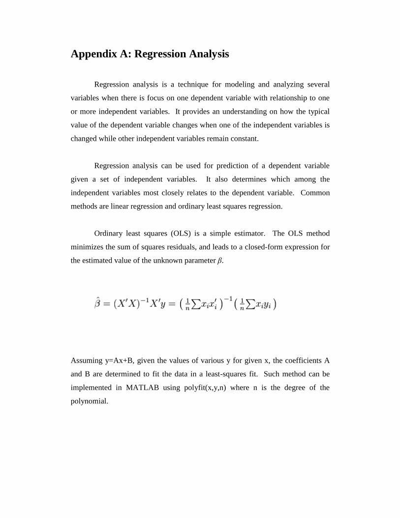
Ordinary least squares (OLS) is a simple estimator. The OLS method
minimizes the sum of squares residuals, and leads to a closed-form expression for
the estimated value of the unknown parameter β.
Assuming y=Ax+B, given the values of various y for given x, the coefficients A
and B are determined to fit the data in a least-squares fit. Such method can be
implemented in MATLAB using polyfit(x,y,n) where n is the degree of the
polynomial.

The following figure is used as an example. Data points are given and a
model is fit to best describe and predict y given x.
A general linear model is given by
Where coefficients βi are determined for each independent variable xi .

Appendix B: Components List & Software
The hardware components used are listed as follows:
Capacitor ........................................................................................... CFAF-1022-4
IR LED .................................................................................. ThorLabs LED1450E
IR LED .................................................................................. ThorLabs LED2050P
Microcontroller .................................................................... Arduino Duemilanove
Multimeter ........................................................................................... Equus #4320
Operation Amplifier ........................................................... Analog Devices OP491
Photodiode ................................................................................... ThorLabs FGA20
Resistor 2Ω ......................................................................................... RDC-2R2-10
Resistor 27 Ω ...................................................................................... RDC-27R-10
Resistor 51 Ω ...................................................................................... RDC-51R-10
Resistor 180 Ω .................................................................................. RDC-180R-10
Resistor 200 Ω .................................................................................. RDC-200R-10
Resistor 1kΩ ......................................................................................... RDC-1K-10
Resistor 3.9kΩ .................................................................................... RDC-3K9-10
Resistor 100kΩ ................................................................................. RDC-100K-10
Software used are as follows:
MATLAB, The MathWorks, Inc.
Arduino 0018
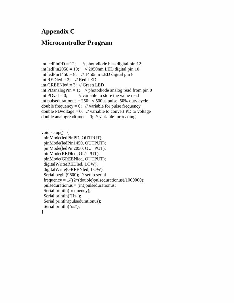
Appendix C
Microcontroller Program
int ledPinPD = 12; // photodiode bias digital pin 12
int ledPin2050 = 10; // 2050nm LED digital pin 10
int ledPin1450 = 8; // 1450nm LED digital pin 8
int REDled = 2; // Red LED
int GREENled = 3; // Green LED
int PDanalogPin = 1; // photodiode analog read from pin 0
int PDval = 0; // variable to store the value read
int pulsedurationus = 250; // 500us pulse, 50% duty cycle
double frequency = 0; // variable for pulse frequency
double PDvoltage = 0; // variable to convert PD to voltage
double analogreadtimer = 0; // variable for reading
void setup()
pinMode(ledPinPD, OUTPUT);
pinMode(ledPin1450, OUTPUT);
pinMode(ledPin2050, OUTPUT);
pinMode(REDled, OUTPUT);
pinMode(GREENled, OUTPUT);
digitalWrite(REDled, LOW);
digitalWrite(GREENled, LOW);
Serial.begin(9600); // setup serial
frequency = 1/((2*(double)pulsedurationus)/1000000);
pulsedurationus = (int)pulsedurationus;
Serial.println(frequency);
Serial.println("Hz");
Serial.println(pulsedurationus);
Serial.println("us");

void loop()
analogreadtimer += 1;
digitalWrite(ledPinPD, HIGH); // set the photodiode on
digitalWrite(ledPin1450, HIGH); // set the 1450nm LED on
digitalWrite(ledPin2050, HIGH); // set the 2050nm LED on
delayMicroseconds(pulsedurationus); // duration 2050nm LED is on
if ((long)analogreadtimer == ((long)frequency/2))
PDval = analogRead(PDanalogPin);
PDvoltage = PDval*4.9;
if (PDvoltage > 1700)
digitalWrite(GREENled, HIGH);
digitalWrite(REDled, HIGH);
if (PDvoltage > 1616)
digitalWrite(REDled, HIGH);
else
digitalWrite(REDled, LOW);
digitalWrite(GREENled, LOW);
// PDvoltage = 0;
Serial.println(PDvoltage);
analogreadtimer = 0;
digitalWrite(ledPin2050, LOW); // set the 2050nm LED off
delayMicroseconds(pulsedurationus); // duration 2050nm LED is off
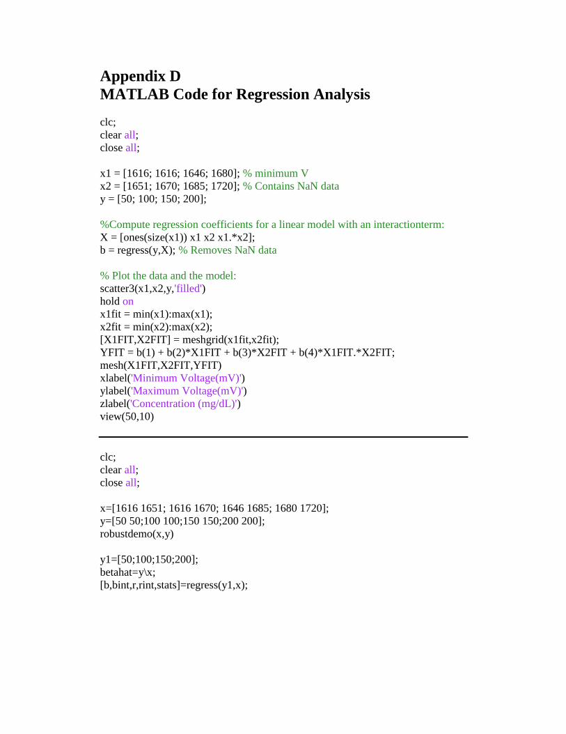
Appendix D
MATLAB Code for Regression Analysis
clc;
clear all;
close all;
x1 = [1616; 1616; 1646; 1680]; % minimum V
x2 = [1651; 1670; 1685; 1720]; % Contains NaN data
y = [50; 100; 150; 200];
%Compute regression coefficients for a linear model with an interactionterm:
X = [ones(size(x1)) x1 x2 x1.*x2];
b = regress(y,X); % Removes NaN data
% Plot the data and the model:
scatter3(x1,x2,y,'filled')
hold on
x1fit = min(x1):max(x1);
x2fit = min(x2):max(x2);
[X1FIT,X2FIT] = meshgrid(x1fit,x2fit);
YFIT = b(1) + b(2)*X1FIT + b(3)*X2FIT + b(4)*X1FIT.*X2FIT;
mesh(X1FIT,X2FIT,YFIT)
xlabel('Minimum Voltage(mV)')
ylabel('Maximum Voltage(mV)')
zlabel('Concentration (mg/dL)')
view(50,10)
clc;
clear all;
close all;
x=[1616 1651; 1616 1670; 1646 1685; 1680 1720];
y=[50 50;100 100;150 150;200 200];
robustdemo(x,y)
y1=[50;100;150;200];
betahat=y\x;
[b,bint,r,rint,stats]=regress(y1,x);

References
[1] Organisation for Economic Co-Operation and Development, “OECD
Health Data 2009 – Frequently Requested Data,” Health Data, 2009.
[Online]. Available: http://www.oecd.org. [Accessed: Apr. 20, 2010].
[2] S. F.Malin, T. L. Ruchiti, T. B. Blank, S. U. Thennadil, and S. L. Monfre,
“Noninvasive prediction of glucose by near-infrared diffuse reflectance
spectroscopy,” Clinical Chemistry, vol. 45, pp. 1651–8, 1999.
[3] O. S. Khalil, “Spectroscopic and clinical aspects of noninvasive glucose
measurements," Clinical Chemistry, vol. 45, no. 2, pp. 165-177, 1999.
[4] C. D. Geddes and J. R. Lakowicz, Topics in Topics in Fluorescence
Spectroscopy: Glucose Sensing, 1st ed. Springer Science+Business Media,
Inc., New York, USA, 2006, vol. 11.
[5] Y. Yu, K. D. Crothall, L. G. Jahn, and M. A. DeStefano, “Laser diode
applications in a continuous blood glucose sensor," Proc. SPIE, vol. 4996,
pp. 268-274, 2003.
[6] K. J. Jeon, I. D. Hwang, S. Hahn, and G. Yoon, “Comparison between
transmittance and reflectance measurements in glucose determination
using near infrared spectroscopy,” Journal of Biomedical Optics, no. 11,
p. 014022, 2006.
[7] A. K. Amerov, J. Chen, G. W. Small, and M. A. Arnold, “Scattering
and absorption effects in the determination of glucose in whole blood by
near-infrared spectroscopy,” Anal. Chem, no. 77, pp. 4587–4594, 2005.
[8] Held. G, Introduction to Light Emitting Diode Technology and
Applications. CRC Press, 2008, pp. 116.
[9] THORLABS, “LED1450E - Epoxy-Encased LED, 1450 nm, 2.0 mW,”
THORLABS, 2007. [Online]. Available: http://www.thorlabs.com.
[Accessed: Jan. 21, 2010].
[10] THORLABS, “LED2050P - LED with a Parabolic Reflector, 2050 nm,
1.1 mW,” THORLABS, 2007. [Online]. Available:
http://www.thorlabs.com. [Accessed: Jan. 21, 2010].
[11] THORLABS, “FGA20 - InGaAs Photodiode, 15 MHz Bandwidth, 1200-
2600 nm, Ø1 mm Active Area,” THORLABS, Jan. 9, 2010. [Online]
Available: http://www.thorlabs.com. [Accessed: Jan. 21, 2010].
[12] Yi Cao, “Partial Least-Squares and Discriminant Analysis,” MATLAB
CENTRAL, Feb. 19, 2008. [Online] Available:
http://www.mathworks.com. [Accessed: Feb. 22, 2010].

Vita
Name:
Place of Birth:
Year of Birth:
Secondary Education:
Dino Sia
Baguio, Philippines
1987
St. Aloysius Gonzaga Secondary
School


![Glucose Transport in Lysosomal Membrane Vesiclestransport across the lysosomal membrane. Uptake ki- netics of [‘%]D-glucose showed a concentration-de- pendent saturable process,](https://img.pdfslide.us/doc/110x75/5f438ac66460a93f27757df2/glucose-transport-in-lysosomal-membrane-transport-across-the-lysosomal-membrane.jpg)