Embed Size (px)
Citation preview
DESIGN OF A MODERN LARGE CAPACITY FeNi SMELTING PLANT
R. Degel, J. Kempken, J. Kunze and R. König
SMS Demag, Eduard Schloemann 4, Düsseldorf, GermanyE-mail: [email protected], [email protected]. [email protected],
roland.kö[email protected]
ABSTRACT
The FeNi technology is currently dominated by high-power submerged arc furnaces, often designed as smelt-er as "two-in-line-solution". To achieve the intended high efficiency, state-of-the-art design in good correla-tion with ores and reductants and an integrated layout of the whole plant is of great importance. Anintroduction will be given to general aspects in the production FeNi, plus a detailed overview of design prin-ciples for large FeNi smelters and finally some examples of innovations and research projects concerning Fe-Ni.
1. HISTORY, APPLICATIONS AND TRENDS
100 years of submerged arc furnace technology (SAF), a remarkable achievement by SMS DEMAG. We areproud of looking back at our involvement in this technology in which SMS DEMAG played a significant rolein the development of this smelter.
Table 1: Major users applying SAF’s
During the last century, the submerged arc furnace has been one of metallurgy’s most amazing diversifiedmelting units which has found many applications in over 20 different industrial areas, including ferro-alloys,iron, silicon metal, copper, lead, zinc, refractory, titanium oxide, calcium carbide, phosphorus and materialsrecycling, etc.[1]. SMS DEMAG has been developing this technology for more than 100 years and has sup-plied a diverse market with about 700 furnaces and major furnace components[2]. Numerous applicationswere constantly developed serving various users[3,4]. Such an evolution was only possible because of tre-mendous efforts in research and development and due to the large range of design solutions.
Ferro-Nickel, Ferro-Chrome, Ferrosilicon, Ferro-Manganese, Silico-Manganese, ……
Alloys / products
Corundum, Mullite, Fused Magnesite, Fused Oxides, Mineral Wool,……
Calcium Carbide, Titanium Slag, Phosphorus, Silicon Metal,……
Iron & steel industry(main applications)
Copper, Lead, Antimon/Bismuth, Zinc, Nickel/Copper Matte, Platinum,…..
Non-ferrous metal industry
Ferro-Tungsten, Ferro-Tantalum, Ferro-Niob, Calcium-Silicon, Ferro-Vanadium, ……..
Iron & steel industry(additional applications)
Refractory & grinding industry*
Chemical & electronic industry
User industries
606 INFACON XI
2. EXPERIENCES IN FENI-SMELTERS AND RECTANGULAR FURNACES
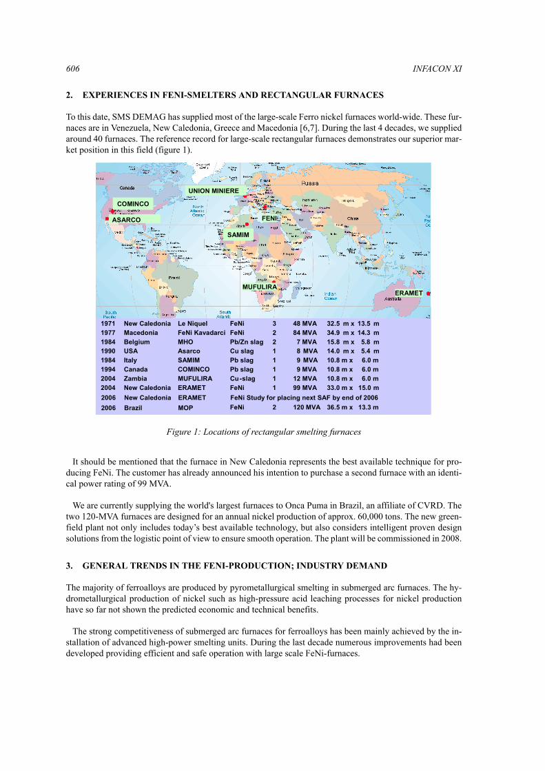
To this date, SMS DEMAG has supplied most of the large-scale Ferro nickel furnaces world-wide. These fur-naces are in Venezuela, New Caledonia, Greece and Macedonia [6,7]. During the last 4 decades, we suppliedaround 40 furnaces. The reference record for large-scale rectangular furnaces demonstrates our superior mar-ket position in this field (figure 1).
It should be mentioned that the furnace in New Caledonia represents the best available technique for pro-ducing FeNi. The customer has already announced his intention to purchase a second furnace with an identi-cal power rating of 99 MVA.
We are currently supplying the world's largest furnaces to Onca Puma in Brazil, an affiliate of CVRD. Thetwo 120-MVA furnaces are designed for an annual nickel production of approx. 60,000 tons. The new green-field plant not only includes today’s best available technology, but also considers intelligent proven designsolutions from the logistic point of view to ensure smooth operation. The plant will be commissioned in 2008.
3. GENERAL TRENDS IN THE FENI-PRODUCTION; INDUSTRY DEMAND
The majority of ferroalloys are produced by pyrometallurgical smelting in submerged arc furnaces. The hy-drometallurgical production of nickel such as high-pressure acid leaching processes for nickel productionhave so far not shown the predicted economic and technical benefits.
The strong competitiveness of submerged arc furnaces for ferroalloys has been mainly achieved by the in-stallation of advanced high-power smelting units. During the last decade numerous improvements had beendeveloped providing efficient and safe operation with large scale FeNi-furnaces.
ASARCO
UNION MINIERE
ERAMET
FENI
COMINCO
SAMIM
48 MVA1971 New Caledonia Le Niquel FeNi 3 32.5 m x 13.5 m1977 Macedonia FeNi Kavadarci FeNi 2 84 MVA 34.9 m x 14.3 m1984 Belgium MHO Pb/Zn slag 2 7 MVA 15.8 m x 5.8 m1990 USA Asarco Cu slag 1 8 MVA 14.0 m x 5.4 m1984 Italy SAMIM Pb slag 1 9 MVA 10.8 m x 6.0 m1994 Canada COMINCO Pb slag 1 9 MVA 10.8 m x 6.0 m2004 Zambia MUFULIRA Cu-slag 1 12 MVA 10.8 m x 6.0 m2004 New Caledonia ERAMET FeNi 1 99 MVA 33.0 m x 15.0 m2006 New Caledonia ERAMET FeNi Study for placing next SAF by end of 2006
MUFULIRA
2006 Brazil MOP FeNi- 2 120 MVA 36.5 m x 13.3 m
Figure 1: Locations of rectangular smelting furnaces
Design of a Modern Large Capacity FeNi Smelting Plant 607
This new demand led to the development of various sidewall cooling concepts as well as to the developmentof AC thyristor controls, which allow better operational control, higher and more efficient power input andresults in less mechanical stress of the furnace equipment.
Sidewall cooling and a thyristor control system are currently successfully in operation at a newly installedsmelter for Eramet in New Caledonia. It represents the world best available large-scale FeNi-smelter. Moredetails will be mentioned later.
Another trend is to design the smelters to a maximum possible capacity. Reasons for this trend are mainly[9,10]:
– Higher energy efficiency– Safer and cleaner working conditions– Fewer spare parts and less wear of critical parts– Less maintenance results in higher plant availability (up to >98 %)– Less manpower– Overall much lower production and investment costs– Complying high environmental standards– More effective de-dusting solutions at lower specific investment
Regarding the high energy efficiency, these may be round or rectangular-shaped furnaces, depending on therequested capacity [9].
SMS DEMAG has found that where more than 60-70 MW nominal furnace load is required, a rectangularfurnace is the best solution from the technical, economical and operational point of view.
When speaking about rectangular furnaces, it should be mentioned that depending on the kind of process,e.g. for copper-slag-cleaning, smaller rectangular SAF's are the best solutions also for furnaces of, e.g., 10MW. SMS DEMAG has introduced a new generation of three-electrode type rectangular furnaces in the mar-ket.
4. DESIGN PRINCIPLES OF LARGE SCALE FENI-SMELTERS
The smelter unit in the FeNi plant comprises
– the calcine transport system,– the slag and metal tapping facilities,– the off gas system,– the refining plant and– the metal granulation plant.
The capacity of each facility is calculated according to the mass and energy balance for the annual amountof dry ore or, respectively, calcined ore to be processed.
The design of the furnace vessel is also driven by the logistics and auxiliaries of the plant. An intelligentsolution for the overall plant layout is the key to a smooth start-up and stable and flexible operation. It is veryimportant that especially conveying systems and the charging system include a certain reserve capacity.
Based on the assumption of 95% availability each of the calcination plant and the smelter unit, the resultingoverall plant availability is approx. 90 %, i.e. approx. 7,900 hours per year [11,12].
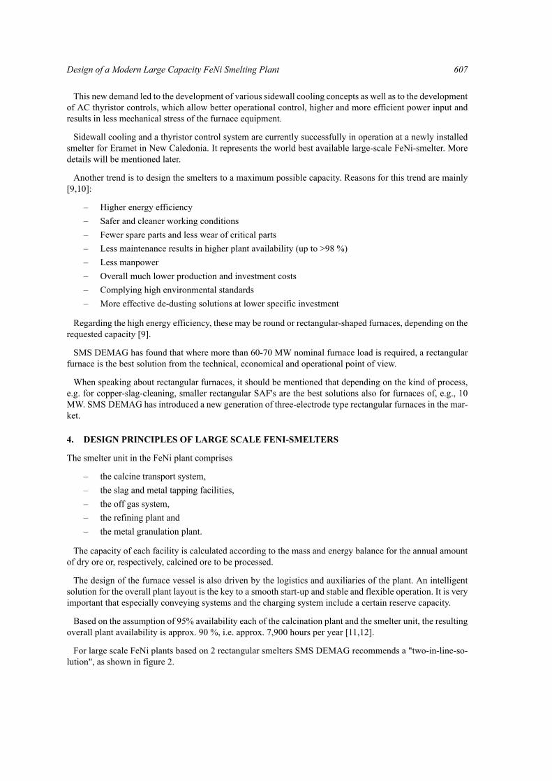
For large scale FeNi plants based on 2 rectangular smelters SMS DEMAG recommends a "two-in-line-so-lution", as shown in figure 2.
608 INFACON XI
5. CALCINE TRANSPORT SYSTEM
The hot calcine will be transferred from the rotary kilns to the furnace charging bins by means of refractorylined transfer containers. The containers are moved via transfer cars between the discharge bins of the rotarykilns and the take over points underneath one of the four hoists. These hoists lift the containers and positionthem above the furnace bin with a demand for calcine for discharge. Each two hoists are serving one bin lineof both electric furnaces.
The availability of two container transfer cars and two hoists for each bin line ensures interchange abilityof these components and therefore allows uninterrupted furnace operation even if one of the transfer cars orhoists fails.
The solution provides the highest flexibility and allows a clear definition of the paths for incoming raw ma-terials and outgoing products.
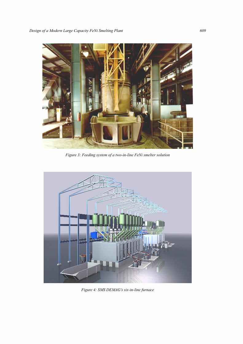
This system has proved its effectiveness on a large scale in several of our reference plants and yields thebest flexibility (figure 3).
6. SUBMERGED ARC FURNACE (SAF)
6.1 Principle of submerged arc furnaces
The principle of a submerged arc furnace is resistance heating. Electric energy is converted into heat and re-duction energy by using the resistance R of the burden or the molten slag, sometimes, e.g. in the case of FeNiproduction, reinforced by the electrical resistance of an arc between the slag and electrode.
6.2 Design principle of a large-scale rectangular FeNi-smelter
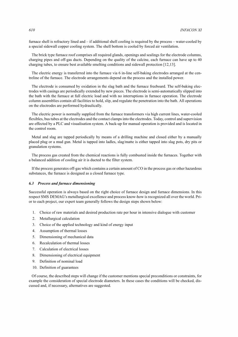
The general arrangement of a 2-in-line rectangular SAF configuration is shown in figure 4. A typical furnacewith slag operation comprises a rectangular furnace shell with 4 – 6 tap holes for slag and 2 for metal. The
Figure 2: Two-in-line rectangular furnace solution
Design of a Modern Large Capacity FeNi Smelting Plant 609
Figure 3: Feeding system of a two-in-line FeNi smelter solution
Figure 4: SMS DEMAG’s six-in-line furnace
610 INFACON XI
furnace shell is refractory lined and – if additional shell cooling is required by the process – water-cooled bya special sidewall copper cooling system. The shell bottom is cooled by forced air ventilation.
The brick type furnace roof comprises all required glands, openings and sealings for the electrode columns,charging pipes and off-gas ducts. Depending on the quality of the calcine, each furnace can have up to 40charging tubes, to ensure best available smelting conditions and sidewall protection [12,13].
The electric energy is transferred into the furnace via 6 in-line self-baking electrodes arranged at the cen-treline of the furnace. The electrode arrangements depend on the process and the installed power.
The electrode is consumed by oxidation in the slag bath and the furnace freeboard. The self-baking elec-trodes with casings are periodically extended by new pieces. The electrode is semi-automatically slipped intothe bath with the furnace at full electric load and with no interruptions in furnace operation. The electrodecolumn assemblies contain all facilities to hold, slip, and regulate the penetration into the bath. All operationson the electrodes are performed hydraulically.
The electric power is normally supplied from the furnace transformers via high current lines, water-cooledflexibles, bus tubes at the electrodes and the contact clamps into the electrodes. Today, control and supervisionare effected by a PLC and visualisation system. A back-up for manual operation is provided and is located inthe control room.
Metal and slag are tapped periodically by means of a drilling machine and closed either by a manuallyplaced plug or a mud gun. Metal is tapped into ladles, slag/matte is either tapped into slag pots, dry pits orgranulation systems.
The process gas created from the chemical reactions is fully combusted inside the furnaces. Together witha balanced addition of cooling air it is ducted to the filter system.
If the process generates off-gas which contains a certain amount of CO in the process gas or other hazardoussubstances, the furnace is designed as a closed furnace type.
6.3 Process and furnace dimensioning
Successful operation is always based on the right choice of furnace design and furnace dimensions. In thisrespect SMS DEMAG’s metallurgical excellence and process know-how is recognized all over the world. Pri-or to each project, our expert team generally follows the design steps shown below:
1. Choice of raw materials and desired production rate per hour in intensive dialogue with customer 2. Metallurgical calculation3. Choice of the applied technology and kind of energy input 4. Assumption of thermal losses5. Dimensioning of mechanical data6. Recalculation of thermal losses7. Calculation of electrical losses8. Dimensioning of electrical equipment9. Definition of nominal load10. Definition of guarantees
Of course, the described steps will change if the customer mentions special preconditions or constraints, forexample the consideration of special electrode diameters. In these cases the conditions will be checked, dis-cussed and, if necessary, alternatives are suggested.
Design of a Modern Large Capacity FeNi Smelting Plant 611
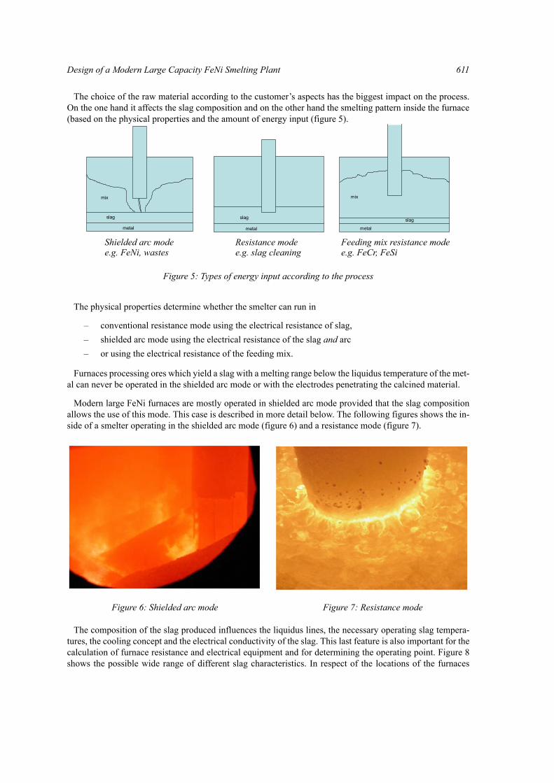
The choice of the raw material according to the customer’s aspects has the biggest impact on the process.On the one hand it affects the slag composition and on the other hand the smelting pattern inside the furnace(based on the physical properties and the amount of energy input (figure 5).
The physical properties determine whether the smelter can run in
– conventional resistance mode using the electrical resistance of slag,– shielded arc mode using the electrical resistance of the slag and arc– or using the electrical resistance of the feeding mix.
Furnaces processing ores which yield a slag with a melting range below the liquidus temperature of the met-al can never be operated in the shielded arc mode or with the electrodes penetrating the calcined material.
Modern large FeNi furnaces are mostly operated in shielded arc mode provided that the slag compositionallows the use of this mode. This case is described in more detail below. The following figures shows the in-side of a smelter operating in the shielded arc mode (figure 6) and a resistance mode (figure 7).
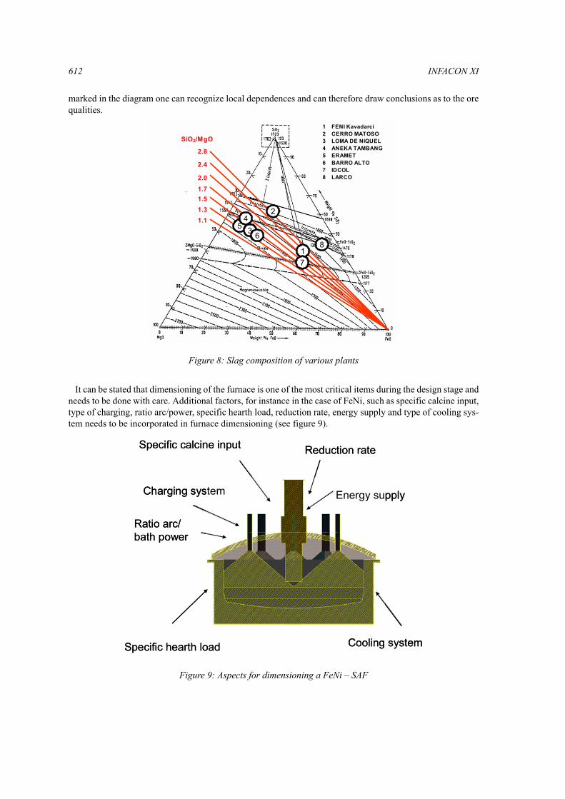
The composition of the slag produced influences the liquidus lines, the necessary operating slag tempera-tures, the cooling concept and the electrical conductivity of the slag. This last feature is also important for thecalculation of furnace resistance and electrical equipment and for determining the operating point. Figure 8shows the possible wide range of different slag characteristics. In respect of the locations of the furnaces
slag metal
mix
metal
slag
metal
slag
mix
Shielded arc modee.g. FeNi, wastes
Resistance modee.g. slag cleaning
Feeding mix resistance modee.g. FeCr, FeSi
Figure 5: Types of energy input according to the process
Figure 6: Shielded arc mode Figure 7: Resistance mode
612 INFACON XI
marked in the diagram one can recognize local dependences and can therefore draw conclusions as to the orequalities.
It can be stated that dimensioning of the furnace is one of the most critical items during the design stage andneeds to be done with care. Additional factors, for instance in the case of FeNi, such as specific calcine input,type of charging, ratio arc/power, specific hearth load, reduction rate, energy supply and type of cooling sys-tem needs to be incorporated in furnace dimensioning (see figure 9).
1
2
34
65
7
3
SiO2/MgO
2.8
2.4
2.01.71.51.31.1
54
6
2
17
3
1 FENI Kavadarci2 CERRO MATOSO3 LOMA DE NIQUEL4 ANEKA TAMBANG5 ERAMET6 BARRO ALTO7 IDCOL8 LARCO
81
2
34
65
7
3
SiO2/MgO
2.8
2.4
2.01.71.51.31.1
54
6
2
17
3
1 FENI Kavadarci2 CERRO MATOSO3 LOMA DE NIQUEL4 ANEKA TAMBANG5 ERAMET6 BARRO ALTO7 IDCOL8 LARCO
8
Figure 8: Slag composition of various plants
Specific hearth load
Specific calcine input Reduction rate
Charging system Energy supply
Cooling system
Ratio arc/ bath power
Specific hearth load
Specific calcine input Reduction rate
Charging system Energy supply
Cooling system
Ratio arc/ bath power
Figure 9: Aspects for dimensioning a FeNi – SAF
Design of a Modern Large Capacity FeNi Smelting Plant 613
6.4 3-D fluid dynamic modelling
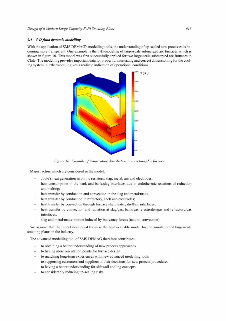
With the application of SMS DEMAG's modelling tools, the understanding of up-scaled new processes is be-coming more transparent. One example is the 3-D-modeling of large-scale submerged arc furnaces which isshown in figure 10. This model was first successfully applied for two large-scale submerged arc furnaces inChile. The modelling provides important data for proper furnace sizing and correct dimensioning for the cool-ing system. Furthermore, it gives a realistic indication of operational conditions.
Major factors which are considered in the model:
– Joule’s heat generation in ohmic resistors: slag, metal, arc and electrodes;– heat consumption in the bank and bank/slag interfaces due to endothermic reactions of reduction
and melting; – heat transfer by conduction and convection in the slag and metal/matte;– heat transfer by conduction in refractory, shell and electrodes;– heat transfer by convection through furnace shell/water, shell/air interfaces;– heat transfer by convection and radiation at slag/gas, bank/gas, electrodes/gas and refractory/gas
interfaces;– slag and metal/matte motion induced by buoyancy forces (natural convection).
We assume that the model developed by us is the best available model for the simulation of large-scalesmelting plants in the industry.
The advanced modelling tool of SMS DEMAG therefore contributes:
– to obtaining a better understanding of new process approaches– to having more orientation points for furnace design– to matching long-term experiences with new advanced modelling tools– to supporting customers and suppliers in their decisions for new process procedures– to having a better understanding for sidewall cooling concepts– to considerably reducing up-scaling risks
Figure 10: Example of temperature distribution in a rectangular furnace
614 INFACON XI
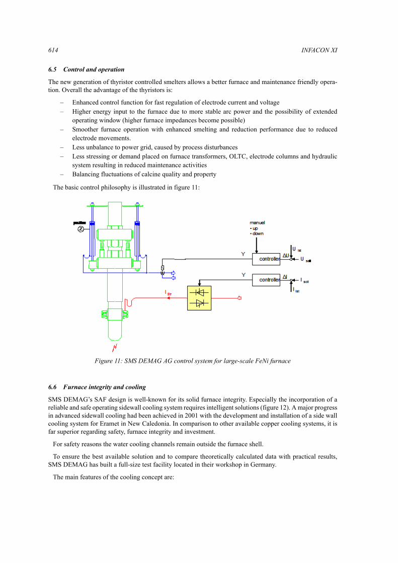
6.5 Control and operation
The new generation of thyristor controlled smelters allows a better furnace and maintenance friendly opera-tion. Overall the advantage of the thyristors is:
– Enhanced control function for fast regulation of electrode current and voltage – Higher energy input to the furnace due to more stable arc power and the possibility of extended
operating window (higher furnace impedances become possible)– Smoother furnace operation with enhanced smelting and reduction performance due to reduced
electrode movements.– Less unbalance to power grid, caused by process disturbances– Less stressing or demand placed on furnace transformers, OLTC, electrode columns and hydraulic
system resulting in reduced maintenance activities– Balancing fluctuations of calcine quality and property
The basic control philosophy is illustrated in figure 11:
6.6 Furnace integrity and cooling
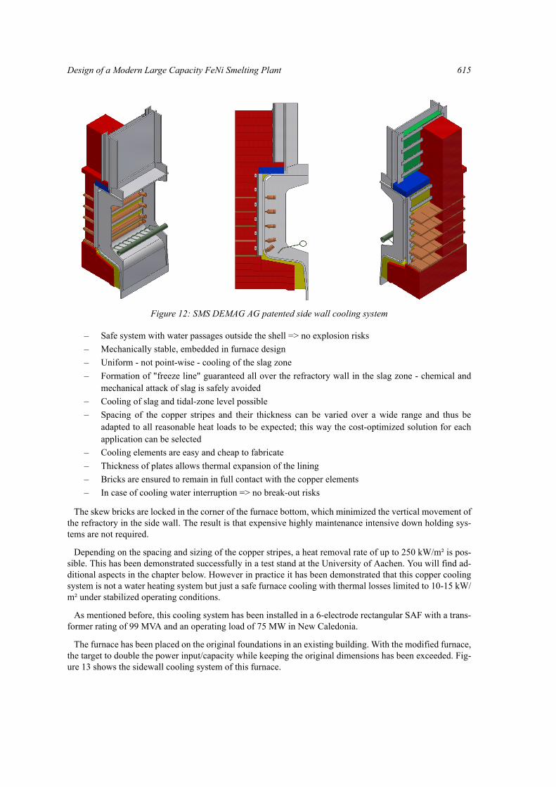
SMS DEMAG’s SAF design is well-known for its solid furnace integrity. Especially the incorporation of areliable and safe operating sidewall cooling system requires intelligent solutions (figure 12). A major progressin advanced sidewall cooling had been achieved in 2001 with the development and installation of a side wallcooling system for Eramet in New Caledonia. In comparison to other available copper cooling systems, it isfar superior regarding safety, furnace integrity and investment.
For safety reasons the water cooling channels remain outside the furnace shell.
To ensure the best available solution and to compare theoretically calculated data with practical results,SMS DEMAG has built a full-size test facility located in their workshop in Germany.
The main features of the cooling concept are:
Figure 11: SMS DEMAG AG control system for large-scale FeNi furnace
Design of a Modern Large Capacity FeNi Smelting Plant 615
– Safe system with water passages outside the shell => no explosion risks– Mechanically stable, embedded in furnace design– Uniform - not point-wise - cooling of the slag zone– Formation of "freeze line" guaranteed all over the refractory wall in the slag zone - chemical and
mechanical attack of slag is safely avoided– Cooling of slag and tidal-zone level possible– Spacing of the copper stripes and their thickness can be varied over a wide range and thus be
adapted to all reasonable heat loads to be expected; this way the cost-optimized solution for eachapplication can be selected
– Cooling elements are easy and cheap to fabricate– Thickness of plates allows thermal expansion of the lining– Bricks are ensured to remain in full contact with the copper elements– In case of cooling water interruption => no break-out risks
The skew bricks are locked in the corner of the furnace bottom, which minimized the vertical movement ofthe refractory in the side wall. The result is that expensive highly maintenance intensive down holding sys-tems are not required.
Depending on the spacing and sizing of the copper stripes, a heat removal rate of up to 250 kW/m² is pos-sible. This has been demonstrated successfully in a test stand at the University of Aachen. You will find ad-ditional aspects in the chapter below. However in practice it has been demonstrated that this copper coolingsystem is not a water heating system but just a safe furnace cooling with thermal losses limited to 10-15 kW/m² under stabilized operating conditions.
As mentioned before, this cooling system has been installed in a 6-electrode rectangular SAF with a trans-former rating of 99 MVA and an operating load of 75 MW in New Caledonia.
The furnace has been placed on the original foundations in an existing building. With the modified furnace,the target to double the power input/capacity while keeping the original dimensions has been exceeded. Fig-ure 13 shows the sidewall cooling system of this furnace.
Figure 12: SMS DEMAG AG patented side wall cooling system
616 INFACON XI
6.7 Further application of side wall copper cooling for rectangular furnaces
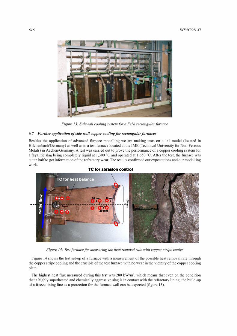
Besides the application of advanced furnace modelling we are making tests on a 1:1 model (located inHilchenbach/Germany) as well as in a test furnace located at the IME (Technical University for Non-FerrousMetals) in Aachen/Germany. A test was carried out to prove the performance of a copper cooling system fora fayalitic slag being completely liquid at 1,300 °C and operated at 1,650 °C. After the test, the furnace wascut in half to get information of the refractory wear. The results confirmed our expectations and our modellingwork.
Figure 14 shows the test set-up of a furnace with a measurement of the possible heat removal rate throughthe copper stripe cooling and the crucible of the test furnace with no wear in the vicinity of the copper coolingplate.
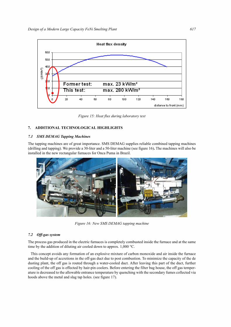
The highest heat flux measured during this test was 280 kW/m², which means that even on the conditionthat a highly superheated and chemically aggressive slag is in contact with the refractory lining, the build-upof a freeze lining line as a protection for the furnace wall can be expected (figure 15).
Figure 13: Sidewall cooling system for a FeNi rectangular furnace
100 mm
20 mm 20 mm
20 mm
20 mm
20 mm
TC for heat balance
TC for abrasion control
wat
erflo
w 100 mm
20 mm 20 mm
20 mm
20 mm
20 mm
20 mm 20 mm
20 mm
20 mm 20 mm
20 mm
20 mm
20 mm
20 mm
20 mm
TC for heat balanceTC for heat balance
TC for abrasion controlTC for abrasion control
wat
erflo
ww
ater
flow 100 m
m
20 mm 20 mm
20 mm
20 mm
20 mm
TC for heat balance
TC for abrasion control
wat
erflo
w 100 mm
20 mm 20 mm
20 mm
20 mm
20 mm
20 mm 20 mm
20 mm
20 mm 20 mm
20 mm
20 mm
20 mm
20 mm
20 mm
TC for heat balanceTC for heat balance
TC for abrasion controlTC for abrasion control
wat
erflo
ww
ater
flow
Figure 14: Test furnace for measuring the heat removal rate with copper stripe cooler
Design of a Modern Large Capacity FeNi Smelting Plant 617
7. ADDITIONAL TECHNOLOGICAL HIGHLIGHTS
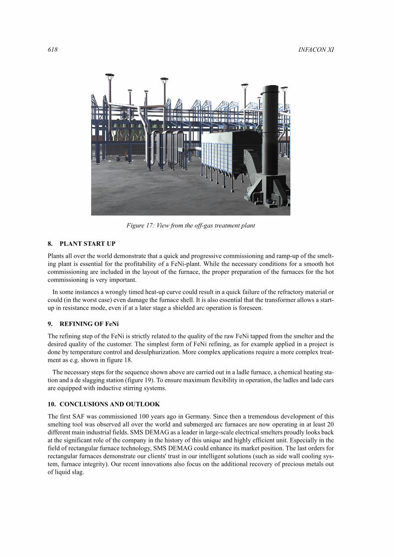
7.1 SMS DEMAG Tapping Machines
The tapping machines are of great importance. SMS DEMAG supplies reliable combined tapping machines(drilling and tapping). We provide a 30-liter and a 50-liter machine (see figure 16). The machines will also beinstalled in the new rectangular furnaces for Onca Puma in Brazil.
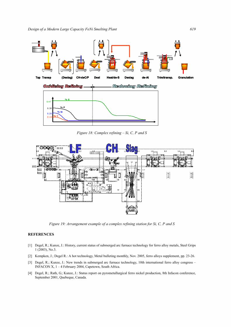
7.2 Off-gas system
The process gas produced in the electric furnaces is completely combusted inside the furnace and at the sametime by the addition of diluting air cooled down to approx. 1,000 °C.
This concept avoids any formation of an explosive mixture of carbon monoxide and air inside the furnaceand the build-up of accretions in the off-gas duct due to post combustion. To minimize the capacity of the dedusting plant, the off gas is routed through a water-cooled duct. After leaving this part of the duct, furthercooling of the off gas is effected by hair-pin coolers. Before entering the filter bag house, the off gas temper-ature is decreased to the allowable entrance temperature by quenching with the secondary fumes collected viahoods above the metal and slag tap holes. (see figure 17).
Figure 15: Heat flux during laboratory test
Figure 16: New SMS DEMAG tapping machine
618 INFACON XI
8. PLANT START UP
Plants all over the world demonstrate that a quick and progressive commissioning and ramp-up of the smelt-ing plant is essential for the profitability of a FeNi-plant. While the necessary conditions for a smooth hotcommissioning are included in the layout of the furnace, the proper preparation of the furnaces for the hotcommissioning is very important.
In some instances a wrongly timed heat-up curve could result in a quick failure of the refractory material orcould (in the worst case) even damage the furnace shell. It is also essential that the transformer allows a start-up in resistance mode, even if at a later stage a shielded arc operation is foreseen.
9. REFINING OF FeNi
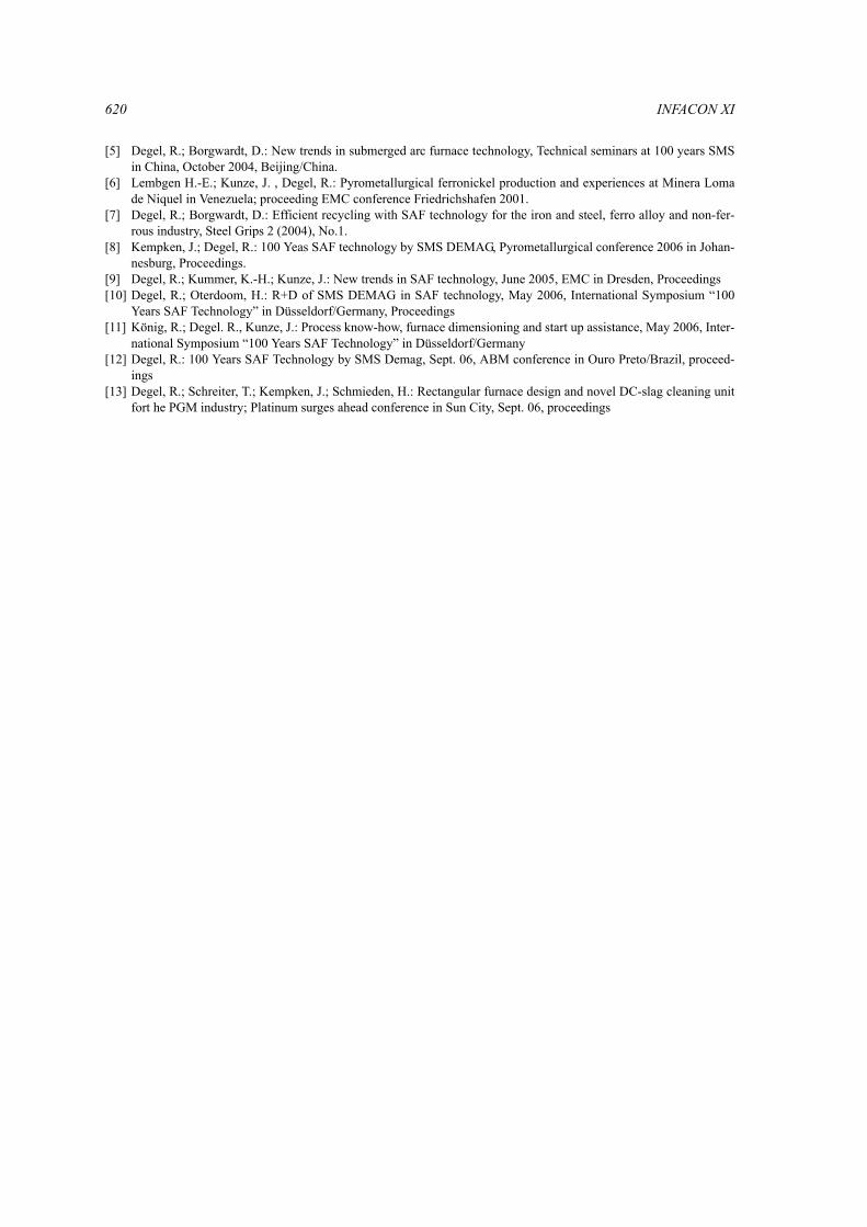
The refining step of the FeNi is strictly related to the quality of the raw FeNi tapped from the smelter and thedesired quality of the customer. The simplest form of FeNi refining, as for example applied in a project isdone by temperature control and desulphurization. More complex applications require a more complex treat-ment as e.g. shown in figure 18.
The necessary steps for the sequence shown above are carried out in a ladle furnace, a chemical heating sta-tion and a de slagging station (figure 19). To ensure maximum flexibility in operation, the ladles and lade carsare equipped with inductive stirring systems.
10. CONCLUSIONS AND OUTLOOK
The first SAF was commissioned 100 years ago in Germany. Since then a tremendous development of thissmelting tool was observed all over the world and submerged arc furnaces are now operating in at least 20different main industrial fields. SMS DEMAG as a leader in large-scale electrical smelters proudly looks backat the significant role of the company in the history of this unique and highly efficient unit. Especially in thefield of rectangular furnace technology, SMS DEMAG could enhance its market position. The last orders forrectangular furnaces demonstrate our clients' trust in our intelligent solutions (such as side wall cooling sys-tem, furnace integrity). Our recent innovations also focus on the additional recovery of precious metals outof liquid slag.
Figure 17: View from the off-gas treatment plant
Design of a Modern Large Capacity FeNi Smelting Plant 619
REFERENCES
[1] Degel, R.; Kunze, J.: History, current status of submerged arc furnace technology for ferro alloy metals, Steel Grips1 (2003), No.3.
[2] Kempken, J.; Degel R.: A hot technology, Metal bulleting monthly, Nov. 2005, ferro alloys supplement, pp. 23-26.
[3] Degel, R.; Kunze, J.: New trends in submerged arc furnace technology, 10th international ferro alloy congress –INFACON X, 1 – 4 February 2004, Capetown, South Africa.
[4] Degel, R.; Rath, G.; Kunze, J.: Status report on pyrometallurgical ferro nickel production, 8th Infacon conference,September 2001, Quebeque, Canada.
0.10
0.20
0.30
0.47% S
% P
% Si
% C
Tap Transp (Deslag) CH-deC/P Desl Heat/de-S Deslag de-Al Trim/transp. Granulation
0.10
0.20
0.30
0.47% S
% P
% Si
% C0.10
0.20
0.30
0.47% S
% P
% Si
% C
Tap Transp (Deslag) CH-deC/P Desl Heat/de-S Deslag de-Al Trim/transp. GranulationTap Transp (Deslag) CH-deC/P Desl Heat/de-S Deslag de-Al Trim/transp. Granulation
Figure 18: Complex refining – Si, C, P and S
Figure 19: Arrangement example of a complex refining station for Si, C, P and S
620 INFACON XI
[5] Degel, R.; Borgwardt, D.: New trends in submerged arc furnace technology, Technical seminars at 100 years SMSin China, October 2004, Beijing/China.
[6] Lembgen H.-E.; Kunze, J. , Degel, R.: Pyrometallurgical ferronickel production and experiences at Minera Lomade Niquel in Venezuela; proceeding EMC conference Friedrichshafen 2001.
[7] Degel, R.; Borgwardt, D.: Efficient recycling with SAF technology for the iron and steel, ferro alloy and non-fer-rous industry, Steel Grips 2 (2004), No.1.
[8] Kempken, J.; Degel, R.: 100 Yeas SAF technology by SMS DEMAG, Pyrometallurgical conference 2006 in Johan-nesburg, Proceedings.
[9] Degel, R.; Kummer, K.-H.; Kunze, J.: New trends in SAF technology, June 2005, EMC in Dresden, Proceedings[10] Degel, R.; Oterdoom, H.: R+D of SMS DEMAG in SAF technology, May 2006, International Symposium “100
Years SAF Technology” in Düsseldorf/Germany, Proceedings[11] König, R.; Degel. R., Kunze, J.: Process know-how, furnace dimensioning and start up assistance, May 2006, Inter-
national Symposium “100 Years SAF Technology” in Düsseldorf/Germany[12] Degel, R.: 100 Years SAF Technology by SMS Demag, Sept. 06, ABM conference in Ouro Preto/Brazil, proceed-
ings[13] Degel, R.; Schreiter, T.; Kempken, J.; Schmieden, H.: Rectangular furnace design and novel DC-slag cleaning unit
fort he PGM industry; Platinum surges ahead conference in Sun City, Sept. 06, proceedings