Embed Size (px)
Citation preview
DESIGN OF A MEDIUM ACCESS CONTROL PROTOCOL THATEXPLOITS THE STRUCTURES OF VEHICULAR NETWORKS
BY
KONG LAM
DISSERTATION
Submitted in partial fulfillment of the requirementsfor the degree of Doctor of Philosophy in Computer Science
in the Graduate College of theUniversity of Illinois at Urbana-Champaign, 2011
Urbana, Illinois
Doctoral Committee:
Professor P. R. Kumar, Chair and Director of ResearchDoctor Fan Bai, General Motors CompanyAssistant Professor Philip B. GodfreyProfessor Lui Raymond ShaProfessor Nitin H. Vaidya

ABSTRACT
Vehicular networks (VANETs) have distinctive structures that distinguish
them in comparison to general mobile ad hoc networks. In this thesis we
identify the relevant special structures that do exist, and show how they can
be exploited to design a MAC layer that provides better performance than a
MAC layer designed without taking such structures into account. Particular
important examples of the structures in VANETs are: (i) Periodic broadcast
is the common transmission pattern due to the requirements of vehicular
safety applications; (ii) GPS is available on nodes; (iii) Node mobility is con-
strained along one-dimensional roadways, and traffic can only move in one
of the two directions of each roadway; and (iv) Traffic moving on one lane
in one direction of a road has group mobility. These structures offer unique
exploitable opportunities for building specific protocols tailored to VANETs
which perform better than other general purpose protocols designed for struc-
tureless networks. We will show that, at the MAC layer, these structures can
be thoroughly exploited to design a protocol based on dynamic TDMA that
is well suited for VANETs. We present the Dynamic Channel Partition and
Reservation (DCPR) Protocol, which is a specific VANET MAC protocol
designed for operating a dynamic TDMA mechanism in a way robust to ve-
hicular mobility, by dynamically partitioning the set of TDMA channels for
the use of vehicles according to their different velocities. DCPR also enhances
the basic dynamic TDMA mechanism with features for proper operation in
a wireless environment with fading. We evaluate DCPR with simulations
via ns-2 and VanetMobiSim, using the Intelligent Driver Model with Lane
Changing. Our simulation results show that DCPR achieves packet loss rates
which are one to two orders of magnitude lower than those obtained by IEEE
802.11p at various vehicle densities and in different vehicular traffic environ-
ments. Moreover, DCPR increases goodput by a factor as high as nine in
a wireless environment with fading compared to a basic dynamic TDMA
ii
protocol. With regard to variations in vehicular traffic, DCPR maintains
stable performance across all levels of traffic asymmetry in a highway sce-
nario. Based on the systematic exploitation of group mobility, we are led to
suggest an overarching design based on the Velocity Differentiated Dynamic
Channel Partition (VDDCP) Mechanism. In the scenarios we have evalu-
ated, DCPR equipped with the VDDCP mechanism performs as well as the
original DCPR, and further evaluation is required to determine if there are
other scenarios of vehicular traffic geometries and intensities in which the
VDDCP mechanism delivers significantly better performance. To summa-
rize, DCPR shows the possibility of building a MAC layer for VANETs that
provides high packet delivery rate, supporting the development of vehicular
safety applications that demand reliability.
iii
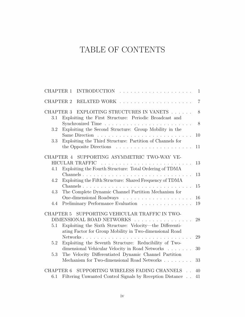
TABLE OF CONTENTS
CHAPTER 1 INTRODUCTION . . . . . . . . . . . . . . . . . . . . 1
CHAPTER 2 RELATED WORK . . . . . . . . . . . . . . . . . . . . 7
CHAPTER 3 EXPLOITING STRUCTURES IN VANETS . . . . . . 83.1 Exploiting the First Structure: Periodic Broadcast and
Synchronized Time . . . . . . . . . . . . . . . . . . . . . . . . 83.2 Exploiting the Second Structure: Group Mobility in the
Same Direction . . . . . . . . . . . . . . . . . . . . . . . . . . 103.3 Exploiting the Third Structure: Partition of Channels for
the Opposite Directions . . . . . . . . . . . . . . . . . . . . . 11
CHAPTER 4 SUPPORTING ASYMMETRIC TWO-WAY VE-HICULAR TRAFFIC . . . . . . . . . . . . . . . . . . . . . . . . . 134.1 Exploiting the Fourth Structure: Total Ordering of TDMA
Channels . . . . . . . . . . . . . . . . . . . . . . . . . . . . . . 134.2 Exploiting the Fifth Structure: Shared Frequency of TDMA
Channels . . . . . . . . . . . . . . . . . . . . . . . . . . . . . . 154.3 The Complete Dynamic Channel Partition Mechanism for
One-dimensional Roadways . . . . . . . . . . . . . . . . . . . 164.4 Preliminary Performance Evaluation . . . . . . . . . . . . . . 19
CHAPTER 5 SUPPORTING VEHICULAR TRAFFIC IN TWO-DIMENSIONAL ROAD NETWORKS . . . . . . . . . . . . . . . . 285.1 Exploiting the Sixth Structure: Velocity—the Differenti-
ating Factor for Group Mobility in Two-dimensional RoadNetworks . . . . . . . . . . . . . . . . . . . . . . . . . . . . . . 29
5.2 Exploiting the Seventh Structure: Reducibility of Two-dimensional Vehicular Velocity in Road Networks . . . . . . . 30
5.3 The Velocity Differentiated Dynamic Channel PartitionMechanism for Two-dimensional Road Networks . . . . . . . . 33
CHAPTER 6 SUPPORTING WIRELESS FADING CHANNELS . . 406.1 Filtering Unwanted Control Signals by Reception Distance . . 41
iv
6.2 More Cautious Channel Status Transitions and CollisionDetection . . . . . . . . . . . . . . . . . . . . . . . . . . . . . 42
6.3 Dynamic Channel Probing Probability . . . . . . . . . . . . . 47
CHAPTER 7 PERFORMANCE EVALUATION . . . . . . . . . . . . 497.1 Packet Loss and Goodput . . . . . . . . . . . . . . . . . . . . 547.2 Beacon Interarrival Time . . . . . . . . . . . . . . . . . . . . . 637.3 Packet Delay and Delay Jitter . . . . . . . . . . . . . . . . . . 657.4 Sensitivity to Timing Errors . . . . . . . . . . . . . . . . . . . 68
CHAPTER 8 CONCLUDING REMARKS . . . . . . . . . . . . . . . 70
REFERENCES . . . . . . . . . . . . . . . . . . . . . . . . . . . . . . . 71
v
CHAPTER 1
INTRODUCTION
A vehicular network is formed by moving vehicles on a road, which are
equipped with wireless communication devices, together with additional wire-
less roadside units. Vehicular networks [1] have distinctive structures com-
pared to general mobile ad hoc networks (MANETs) [2]. In fact this is the
reason that one expects greater success for vehicular networks in compari-
son to protocols for ad hoc networks which are structureless. In particular,
VANETs have the following distinctive structures, which we will show we
can exploit in order to obtain better performance:
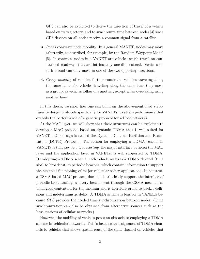
1. Periodic broadcast is the predominant form of communication between
nodes. This is because major vehicular safety applications build on
the platform of vehicles’ periodic broadcast of beacons for their very
functioning. These periodic beacons contain the instantaneous telem-
atics data of the transmitting vehicle, such as its position, velocity,
acceleration, etc., together with applicable warning signals. Applica-
tions built on top of periodic broadcast include Cooperative Collision
Warning, which has received wide interest from the research commu-
nity, Stopped or Slow Vehicle Adviser, V2V Post Crash Notification,
and Cooperative Violation Warning [3]. Since they all utilize the same
common information, it is convenient to consolidate and transmit in-
formation for a variety of applications in a single beacon. As a result,
every node in a vehicular network repeatedly transmits such a packet
every fixed time interval. Periodic broadcast is therefore a major inter-
face between the application layer and the MAC layer in VANETs.
2. GPS is available on all nodes which participate in a vehicular network.
GPS is standard equipment on intelligent vehicles, as major vehicular
safety applications require the position of the vehicle for their very
functioning. Apart from providing position information of a vehicle,
1
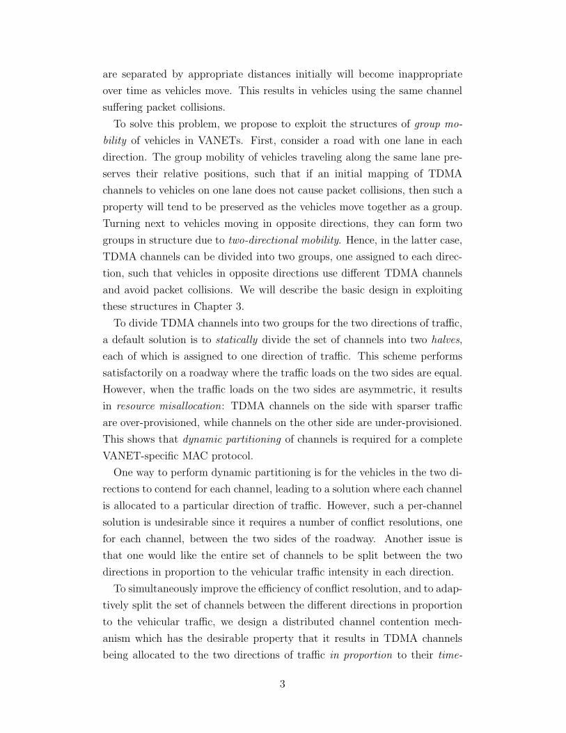
GPS can also be exploited to derive the direction of travel of a vehicle
based on its trajectory, and to synchronize time between nodes [4] since
GPS devices on all nodes receive a common signal from a satellite.
3. Roads constrain node mobility. In a general MANET, nodes may move
arbitrarily, as described, for example, by the Random Waypoint Model
[5]. In contrast, nodes in a VANET are vehicles which travel on con-
strained roadways that are intrinsically one-dimensional. Vehicles on
such a road can only move in one of the two opposing directions.
4. Group mobility of vehicles further constrains vehicles traveling along
the same lane. For vehicles traveling along the same lane, they move
as a group, as vehicles follow one another, except when overtaking using
another lane.
In this thesis, we show how one can build on the above-mentioned struc-
tures to design protocols specifically for VANETs, to attain performance that
exceeds the performance of a generic protocol for ad hoc networks.
At the MAC layer, we will show that these structures can be exploited to
develop a MAC protocol based on dynamic TDMA that is well suited for
VANETs. Our design is named the Dynamic Channel Partition and Reser-
vation (DCPR) Protocol. The reason for employing a TDMA scheme in
VANETs is that periodic broadcasting, the major interface between the MAC
layer and the application layer in VANETs, is well supported by TDMA.
By adopting a TDMA scheme, each vehicle reserves a TDMA channel (time
slot) to broadcast its periodic beacons, which contain information to support
the essential functioning of major vehicular safety applications. In contrast,
a CSMA-based MAC protocol does not intrinsically support the interface of
periodic broadcasting, as every beacon sent through the CSMA mechanism
undergoes contention for the medium and is therefore prone to packet colli-
sions and indeterministic delay. A TDMA scheme is feasible in VANETs be-
cause GPS provides the needed time synchronization between nodes. (Time
synchronization can also be obtained from alternative sources such as the
base stations of cellular networks.)
However, the mobility of vehicles poses an obstacle to employing a TDMA
scheme in vehicular networks. This is because an assignment of TDMA chan-
nels to vehicles that allows spatial reuse of the same channel on vehicles that
2
are separated by appropriate distances initially will become inappropriate
over time as vehicles move. This results in vehicles using the same channel
suffering packet collisions.
To solve this problem, we propose to exploit the structures of group mo-
bility of vehicles in VANETs. First, consider a road with one lane in each
direction. The group mobility of vehicles traveling along the same lane pre-
serves their relative positions, such that if an initial mapping of TDMA
channels to vehicles on one lane does not cause packet collisions, then such a
property will tend to be preserved as the vehicles move together as a group.
Turning next to vehicles moving in opposite directions, they can form two
groups in structure due to two-directional mobility. Hence, in the latter case,
TDMA channels can be divided into two groups, one assigned to each direc-
tion, such that vehicles in opposite directions use different TDMA channels
and avoid packet collisions. We will describe the basic design in exploiting
these structures in Chapter 3.
To divide TDMA channels into two groups for the two directions of traffic,
a default solution is to statically divide the set of channels into two halves,
each of which is assigned to one direction of traffic. This scheme performs
satisfactorily on a roadway where the traffic loads on the two sides are equal.
However, when the traffic loads on the two sides are asymmetric, it results
in resource misallocation: TDMA channels on the side with sparser traffic
are over-provisioned, while channels on the other side are under-provisioned.
This shows that dynamic partitioning of channels is required for a complete
VANET-specific MAC protocol.
One way to perform dynamic partitioning is for the vehicles in the two di-
rections to contend for each channel, leading to a solution where each channel
is allocated to a particular direction of traffic. However, such a per-channel
solution is undesirable since it requires a number of conflict resolutions, one
for each channel, between the two sides of the roadway. Another issue is
that one would like the entire set of channels to be split between the two
directions in proportion to the vehicular traffic intensity in each direction.
To simultaneously improve the efficiency of conflict resolution, and to adap-
tively split the set of channels between the different directions in proportion
to the vehicular traffic, we design a distributed channel contention mech-
anism which has the desirable property that it results in TDMA channels
being allocated to the two directions of traffic in proportion to their time-
3
varying asymmetric traffic intensities. To attain this goal with efficiency, we
exploit the total ordering on the set of TDMA channels—specifically that
a boundary on the contiguous set of channels is sufficient to partition them
for the two directions. Our design removes the need of contention for ev-
ery single channel between the two directions of traffic, and replaces it with
a contention for just one boundary. The details of the Dynamic Channel
Partition Mechanism are described in Chapter 4.
The above design applies to vehicular traffic on a single roadway, and does
not take into account the different speeds of vehicles on different lanes of
a roadway, albeit traveling in the same direction. To solve the problem of
TDMA channel collisions due to vehicular mobility in a complete road net-
work, we identify that velocity—direction and speed—of a vehicle is the prop-
erty that differentiates vehicles in different mobility groups, or traffic flows,
within which vehicles travel together with group mobility. For example, ve-
hicles traveling on different roads have different directions of movement, and
thus different velocities; vehicles traveling at different speeds along a multi-
lane roadway also have different velocities as well. By therefore differentiating
vehicles according to their velocities, we are able to identify different mobility
groups in a road network. Disjoint subsets of TDMA channels can then be
allocated to different groups to avoid TDMA channel collisions due to vehic-
ular mobility. The allocation can be dynamically and distributedly done by
a two-dimensional extension of the Dynamic Channel Partition Mechanism,
in which multiple mobility groups of vehicles contend for multiple boundaries
on the contiguous set of TDMA channels to partition and allocate them. We
describe the details of the Velocity Differentiated Dynamic Channel Partition
(VDDCP) Mechanism in Chapter 5.
A very important problem in adopting a dynamic TDMA scheme in ve-
hicular networks is the problem of fading, which is an inherent property of
wireless channels. In a fading environment, it is necessary to differentiate a
transmission that has failed due to a collision from one that has failed due
to fading, i.e., bad channel gain or noise. In particular, one would want a
node to only drop its reserved TDMA channel when a real collision occurs,
which happens when another vehicle is using the same TDMA channel in its
vicinity, rather than when it loses a packet due to fading. Another problem
caused by fading is that a node may also receive unwanted signaling informa-
tion about the statuses of TDMA channels from a distant node, by chance.
4
This too can cause a node to mistakenly assume that a channel has already
been claimed by another node in its nearby vicinity, which is also not desir-
able. We solve this problem by again exploiting the structures of VANETs,
in this case the property that due to the availability of GPS, the transmit-
ted packets can carry position information of the transmitting vehicle in the
payload or header of VANET packets. Such information enables a node to
calculate the distance to the transmitter of a packet, and filter unwanted
TDMA channel status information from a vehicle beyond the area of inter-
est. The critical enhancements of the DCPR protocol needed for adapting
to the ever present fading environment are described in Chapter 6.
We have evaluated the DCPR protocol with simulations via ns-2 and
VanetMobiSim, using the Intelligent Driver Model with Lane Changing, to
compare its performance against IEEE 802.11p and a basic dynamic TDMA
protocol, at various levels of vehicle density, and in different vehicular traffic
environments. The latter include a highway scenario, and two urban scenar-
ios, one with a Manhattan Grid roadway network structure, and the other
with a more irregular structure. Our simulation results show that DCPR
achieves packet loss rates that are one to two orders of magnitude lower than
those achieved by IEEE 802.11p in all scenarios. Moreover, DCPR increases
the goodput by a factor as high as nine in a wireless environment with fad-
ing compared to a basic dynamic TDMA protocol. With regard to variations
in vehicular traffic, DCPR maintains stable performance across all levels of
traffic asymmetry in a highway scenario. In the scenarios we have evaluated,
DCPR equipped with the VDDCP mechanism performs as well as the origi-
nal DCPR, and further evaluation is required to determine if there are other
scenarios of vehicular traffic geometries and intensities in which the VDDCP
mechanism delivers significantly better performance. We have also evaluated
the impact of timing errors on the DCPR protocol.
The organization of this thesis is as follows. We first review related work
in Chapter 2. In Chapter 3, we describe how DCPR exploits the structures
of VANETs. In Chapter 4, we describe in detail how we design the DCPR
protocol to support asymmetric vehicular traffic by exploiting the available
structures in VANETs and TDMA. In Chapter 5, we explain how the DCPR
protocol can be extended to support traffic in a two-dimensional road network
by differentiating vehicles by their velocities. In Chapter 6, we introduce
the adaptation of the DCPR protocol to a fading environment to ensure its
5
proper operation. We evaluate our overall design in Chapter 7, and conclude
in Chapter 8.
Some of the material in this thesis has been presented in our prior publi-
cations [6, 7].
6
CHAPTER 2
RELATED WORK
In this chapter, we give an overview of previous work that is related to our
work.
Our work is the first work that proposes to exploit the structures of
VANETs to build a specific MAC protocol for VANETs. There are pre-
vious works that propose a MAC layer for vehicular networks based on dy-
namic TDMA, but the particular structures of VANETs are not thoroughly
exploited. They include FleetNet [4], Reliable R-ALOHA [8], and ADHOC-
MAC [9]. In [10], a power control algorithm is built upon the MAC layer of
FleetNet to make it robust to varying vehicle density.
TDMA has also been proposed for use in wireless systems other than ve-
hicular networks. Yet, these systems have different structures than VANETs,
which may or may not support the employment of TDMA. Examples include
Packet Reservation Multiple Access for multimedia communication in gen-
eral wireless systems [11], UTRA TDD for 3G cellular networks [12], IEEE
802.16 (WiMAX) TDD for wireless broadband access [13], and Bluetooth for
personal area networks [14].
Another line of research focuses on studying and improving the broadcast
performance of IEEE 802.11p, the current MAC standard for VANETs, or
IEEE 802.11 standards in general. To study the broadcast performance of
IEEE 802.11, an analytical model is constructed in [15], and detailed simu-
lations are conducted under different radio propagation models in [16]. To
improve broadcast performance in VANETs, priority access mechanisms in
IEEE 802.11e are employed in [17]. In [18], the authors propose a scheme to
adjust contention window size, based on local detection of network congestion
through observing sequence numbers in received packets.
7
CHAPTER 3
EXPLOITING STRUCTURES IN VANETS
In this chapter, we describe in detail how the structures in VANETs can
be exploited to build a MAC protocol for VANETs specifically for perfor-
mance improvements. We call our design the Dynamic Channel Partition
and Reservation (DCPR) protocol.
3.1 Exploiting the First Structure: Periodic Broadcast
and Synchronized Time
Periodic broadcasting is the predominant important form of communication
between nodes in VANETs for safety applications. It is the common inter-
face on which major vehicular safety applications are built. A representative
example is “Cooperative Collision Warning,” in which each vehicle period-
ically broadcasts its kinematic information, including its position, velocity,
and acceleration. Each vehicle may then listen for kinematic information
embedded in periodic beacons broadcast by neighboring vehicles to compute
the likelihood of potential vehicular collisions. Measures can then be taken
to prevent a vehicular collision from happening, such as automatic braking
[3].
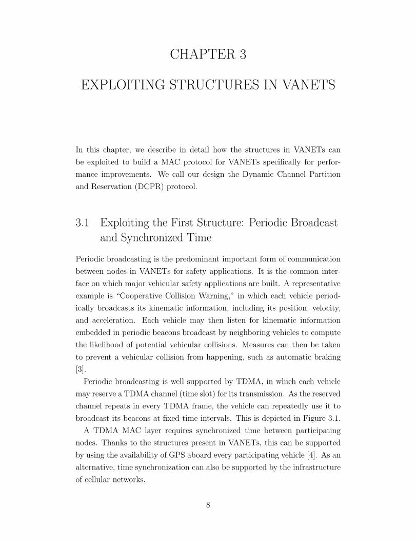
Periodic broadcasting is well supported by TDMA, in which each vehicle
may reserve a TDMA channel (time slot) for its transmission. As the reserved
channel repeats in every TDMA frame, the vehicle can repeatedly use it to
broadcast its beacons at fixed time intervals. This is depicted in Figure 3.1.
A TDMA MAC layer requires synchronized time between participating
nodes. Thanks to the structures present in VANETs, this can be supported
by using the availability of GPS aboard every participating vehicle [4]. As an
alternative, time synchronization can also be supported by the infrastructure
of cellular networks.
8
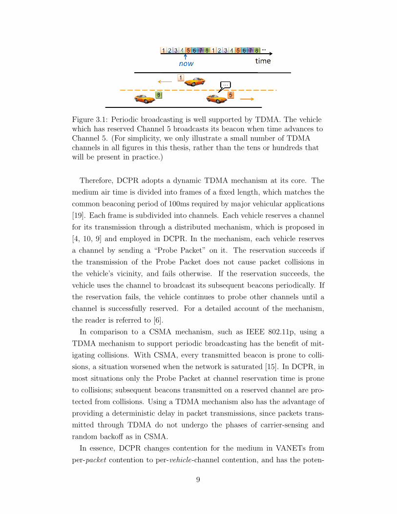
Figure 3.1: Periodic broadcasting is well supported by TDMA. The vehiclewhich has reserved Channel 5 broadcasts its beacon when time advances toChannel 5. (For simplicity, we only illustrate a small number of TDMAchannels in all figures in this thesis, rather than the tens or hundreds thatwill be present in practice.)
Therefore, DCPR adopts a dynamic TDMA mechanism at its core. The
medium air time is divided into frames of a fixed length, which matches the
common beaconing period of 100ms required by major vehicular applications
[19]. Each frame is subdivided into channels. Each vehicle reserves a channel
for its transmission through a distributed mechanism, which is proposed in
[4, 10, 9] and employed in DCPR. In the mechanism, each vehicle reserves
a channel by sending a “Probe Packet” on it. The reservation succeeds if
the transmission of the Probe Packet does not cause packet collisions in
the vehicle’s vicinity, and fails otherwise. If the reservation succeeds, the
vehicle uses the channel to broadcast its subsequent beacons periodically. If
the reservation fails, the vehicle continues to probe other channels until a
channel is successfully reserved. For a detailed account of the mechanism,
the reader is referred to [6].
In comparison to a CSMA mechanism, such as IEEE 802.11p, using a
TDMA mechanism to support periodic broadcasting has the benefit of mit-
igating collisions. With CSMA, every transmitted beacon is prone to colli-
sions, a situation worsened when the network is saturated [15]. In DCPR, in
most situations only the Probe Packet at channel reservation time is prone
to collisions; subsequent beacons transmitted on a reserved channel are pro-
tected from collisions. Using a TDMA mechanism also has the advantage of
providing a deterministic delay in packet transmissions, since packets trans-
mitted through TDMA do not undergo the phases of carrier-sensing and
random backoff as in CSMA.
In essence, DCPR changes contention for the medium in VANETs from
per-packet contention to per-vehicle-channel contention, and has the poten-
9
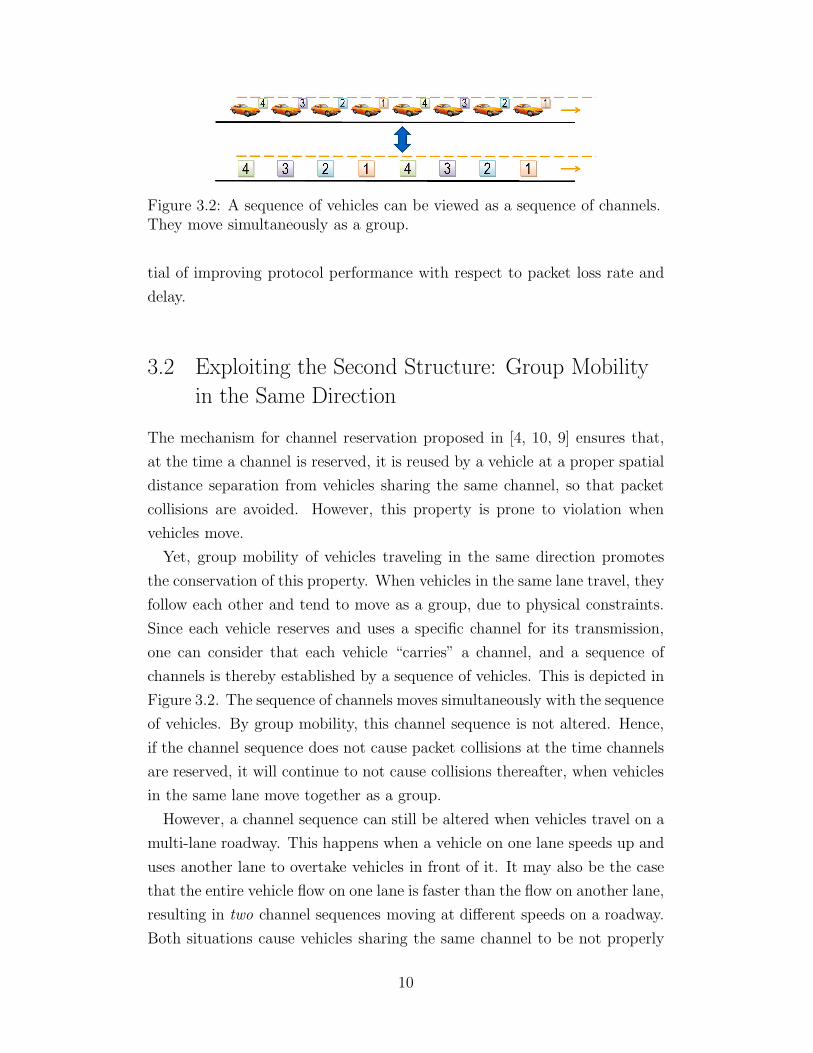
Figure 3.2: A sequence of vehicles can be viewed as a sequence of channels.They move simultaneously as a group.
tial of improving protocol performance with respect to packet loss rate and
delay.
3.2 Exploiting the Second Structure: Group Mobility
in the Same Direction
The mechanism for channel reservation proposed in [4, 10, 9] ensures that,
at the time a channel is reserved, it is reused by a vehicle at a proper spatial
distance separation from vehicles sharing the same channel, so that packet
collisions are avoided. However, this property is prone to violation when
vehicles move.
Yet, group mobility of vehicles traveling in the same direction promotes
the conservation of this property. When vehicles in the same lane travel, they
follow each other and tend to move as a group, due to physical constraints.
Since each vehicle reserves and uses a specific channel for its transmission,
one can consider that each vehicle “carries” a channel, and a sequence of
channels is thereby established by a sequence of vehicles. This is depicted in
Figure 3.2. The sequence of channels moves simultaneously with the sequence
of vehicles. By group mobility, this channel sequence is not altered. Hence,
if the channel sequence does not cause packet collisions at the time channels
are reserved, it will continue to not cause collisions thereafter, when vehicles
in the same lane move together as a group.
However, a channel sequence can still be altered when vehicles travel on a
multi-lane roadway. This happens when a vehicle on one lane speeds up and
uses another lane to overtake vehicles in front of it. It may also be the case
that the entire vehicle flow on one lane is faster than the flow on another lane,
resulting in two channel sequences moving at different speeds on a roadway.
Both situations cause vehicles sharing the same channel to be not properly
10
separated, resulting in packet collisions when they transmit simultaneously.
We will address this issue in Chapter 5.
3.3 Exploiting the Third Structure: Partition of
Channels for the Opposite Directions
Compared to vehicles traveling in the same direction, vehicles moving in
opposing directions result in rapid change in the network topology. If the
channel reservation mechanism in [4, 10, 9] is directly applied to vehicles
traveling in opposing directions, vehicles sharing the same channel will en-
counter one another as they move, resulting in packet collisions, and hence
channel reconfigurations, or, interruptions.
Yet, a solution can be sought by exploiting a structure of VANETs, in
which vehicles traveling on a roadway form two groups—one group in one di-
rection of movement, and the other in the opposite direction. Hence, TDMA
channels can be partitioned into two groups accordingly, and be allocated to
each direction. Then, vehicles will only reserve channels allocated to their
direction, and vehicles in opposite directions will not share channels. Thus,
the situation where two vehicles sharing the same channel move against each
other in opposing directions will not exist. Note that a vehicle may deter-
mine which direction group it belongs to, since its GPS can provide a trace
of its trajectory, and hence its direction of movement.
Therefore, the question becomes how to partition the channels into two
groups. A default solution is to statically divide the channels into two equal
halves, as shown in Figure 3.3a. This scheme performs satisfactorily when the
traffic intensities in the two directions are equal. However, when the traffic
intensities are asymmetric, which is common in peak hours, it will cause
degraded performance due to resource misallocation. This is verified by our
simulations in Section 4.4. The reason is that TDMA channels are over-
provisioned for the direction with sparse traffic, and hence are underutilized,
while channels are under-provisioned on the side with dense traffic, which
may result in some vehicles failing to secure a reserved channel that causes
no interference to other vehicles in the vicinity. This is depicted in Figure
3.3b.
Thus, DCPR requires a mechanism to dynamically partition the channels
11
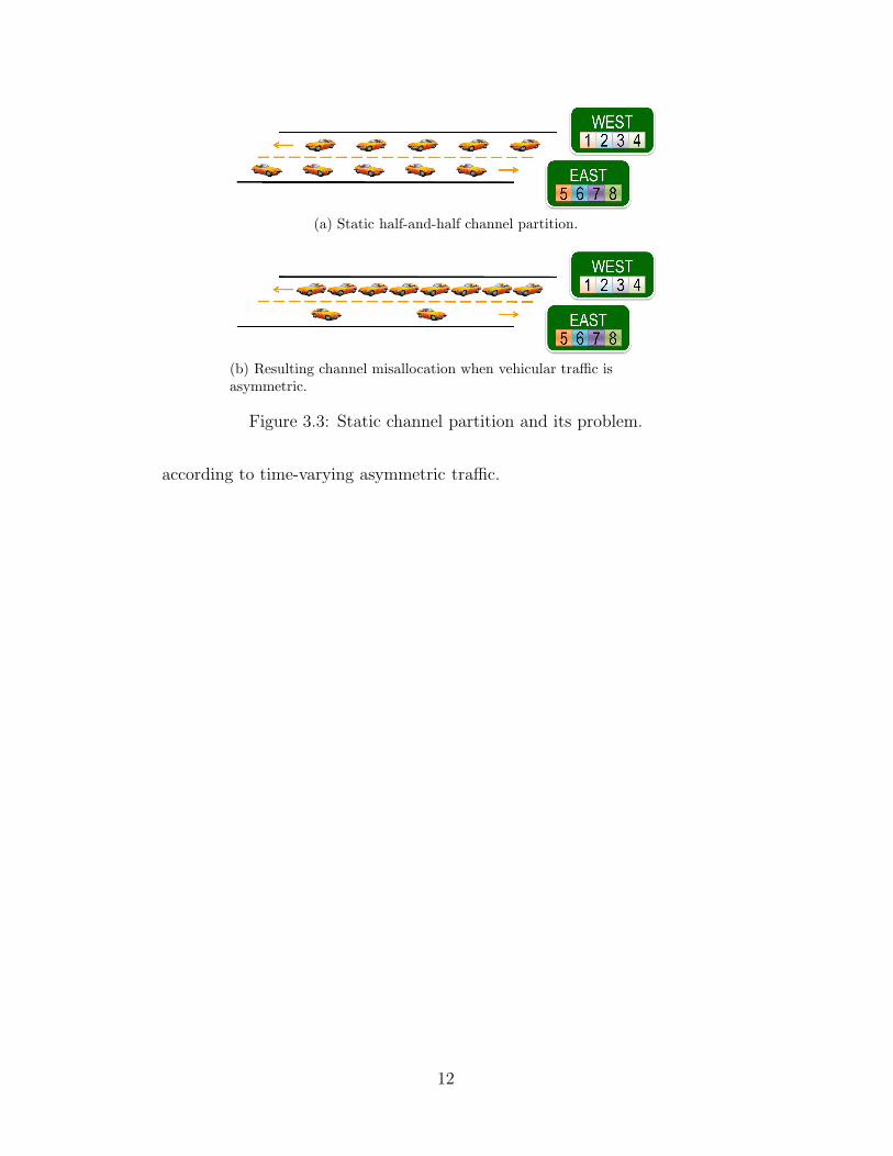
(a) Static half-and-half channel partition.
(b) Resulting channel misallocation when vehicular traffic isasymmetric.
Figure 3.3: Static channel partition and its problem.
according to time-varying asymmetric traffic.
12
CHAPTER 4
SUPPORTING ASYMMETRIC TWO-WAY
VEHICULAR TRAFFIC
To support asymmetric two-way traffic, we aim at designing a mechanism
which allocates TDMA channels to the two directions of traffic in propor-
tion to their asymmetric and time-varying vehicular traffic intensities. To
preserve the distributed nature of vehicular networks, it is desirable that the
mechanism for channel allocation is distributed among vehicles. Hence, our
target is to develop a distributed channel contention mechanism that can be
used by the vehicles in opposing directions, resulting in channels that are
“allocated” distributedly through contention.
In the sequel, we begin by introducing how to exploit the structures of
VANETs and TDMA in two important ways to achieve an efficient design.
Then, we describe the overall implementation of the Dynamic Channel Par-
tition (DCP) Mechanism in DCPR for a one-dimensional roadway.
4.1 Exploiting the Fourth Structure: Total Ordering of
TDMA Channels
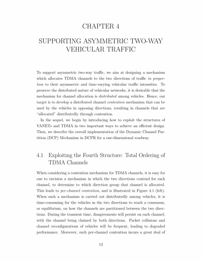
When considering a contention mechanism for TDMA channels, it is easy for
one to envision a mechanism in which the two directions contend for each
channel, to determine to which direction group that channel is allocated.
This leads to per-channel contention, and is illustrated in Figure 4.1 (left).
When such a mechanism is carried out distributedly among vehicles, it is
time-consuming for the vehicles in the two directions to reach a consensus,
or equilibrium, on how the channels are partitioned between the two direc-
tions. During the transient time, disagreements will persist on each channel,
with the channel being claimed by both directions. Packet collisions and
channel reconfigurations of vehicles will be frequent, leading to degraded
performance. Moreover, such per-channel contention incurs a great deal of
13
Figure 4.1: Per-channel contention can be eliminated and replaced bycontention for just one boundary by taking advantage of two-directionalvehicular movement and the total ordering of TDMA channels.
overhead in resolving contention for each and every channel, since there are
a large number of channels.
However, a careful inspection of the structures of TDMA channels and
vehicular traffic leads to a different efficient solution. We observe that: (i)
There are only two directions of vehicular movement on a roadway; and (ii)
The set of TDMA channels has a total order. That is, the set of TDMA
channels can be ordered linearly and indexed. It follows from this that a
single boundary is sufficient to partition the channels into two groups: Chan-
nels with indices smaller than the boundary can form one group serving one
direction of traffic, and channels with indices larger than the boundary form
another group serving the other direction of traffic. Since there are only
two directions of movement, and hence two direction groups of vehicles, one
group of channels is assigned to one direction group, and the other group of
channels to the other direction. Thus, it is sufficient for the two directions
to contend to adjust one boundary to achieve an allocation over all channels.
This is illustrated in Figure 4.1 (right).
In essence, our design transforms channel contention between the two di-
rections of traffic from per-channel contention to one-boundary contention.
This greatly increases the efficiency in partitioning the channels between the
two directions. The convergence time, i.e., the time which the two directions
of traffic require to reach a consensus on how the channels are partitioned,
is shortened, and hence packet collisions and channel reconfigurations of ve-
hicles are reduced, resulting in improved performance.
14

Figure 4.2: Vehicles without a reserved channel are hidden in thecommunication domain.
4.2 Exploiting the Fifth Structure: Shared Frequency
of TDMA Channels
Recall that our goal is to allocate to each direction of movement a number
of channels that is proportional to the vehicular traffic intensity in that di-
rection. To achieve this goal, the above-mentioned boundary should ideally
be set to the point which divides the set of channels in exact proportion to
the traffic intensities of the two directions. Hence, it is necessary for the
system to be able to estimate the traffic intensities in the two directions.
Note that we also have the constraint that the estimation should be based
only on information obtainable in the communication domain, without any
assistance from additional physical infrastructure installed along roads to
measure traffic intensities.
Therefore, our design has to “observe” vehicles in both directions in the
communication domain, to estimate the ratio of traffic intensities in the two
directions. We will say that a vehicle is “observable” in the communication
domain if it transmits beacons that contain its identifier.
However, a fundamental problem is encountered when we want to observe
vehicles in the communication domain only through their beacons. With
a dynamic TDMA-based protocol like DCPR, a vehicle can only transmit
beacons after it has reserved a TDMA channel. Hence, vehicles which have
not yet reserved a channel are “hidden” from others in the communication
domain, since they cannot transmit beacons to show their presence. This
situation is shown in Figure 4.2. Vehicles which have such a reserved channel
are called “visible” vehicles in the following. When a subset of vehicles is not
observable, the system will not be able to arrive at an accurate estimate of
the ratio of traffic intensities in the two directions.
We tackle this problem by exploiting the fact that TDMA channels share
a common frequency, which implies that vehicles do not need to switch their
15

Figure 4.3: A TDMA channel, Channel 8 in this example, is set apart andused as the “Presence Indication (PI) Channel.”
antennae to a different frequency to listen on any particular channel. This
unique structure of TDMA enables us to use the channels flexibly. In or-
der to keep track of hidden vehicles on a roadway, we dedicate one TDMA
channel, and use it as the “Presence Indication (PI) Channel” for hidden
vehicles, as shown in Figure 4.3. Each hidden vehicle is required to transmit
a “Presence Indication Packet” on this channel in each TDMA frame, with
a low probability, with the packet containing its direction of movement, ob-
tainable from its GPS. By listening to packets on this channel, every vehicle
can empirically estimate the probability that the PI Channel is idle, and the
probability that a PI Packet is successfully received in each direction, as we
will show in the sequel. These statistics can be used to estimate the number
of hidden vehicles in each direction. With this PI Channel, the system can
observe both visible and hidden vehicles in both directions, and an accurate
estimate of the ratio of traffic intensities in the two directions can be made.
Note that the use of the PI Channel only consumes a minimal portion of the
channel resource, as it is just one TDMA channel out of tens or hundreds
of channels in a TDMA frame in practice. Moreover, the length of the PI
Channel can be made shorter than a normal channel for data transmission,
since the PI Packet does not contain any application payload, and is small.
4.3 The Complete Dynamic Channel Partition
Mechanism for One-dimensional Roadways
We now describe the complete design of our Dynamic Channel Partition
Mechanism for one-dimensional roadways.
The mechanism is distributed among vehicles. Each vehicle carries out
the tasks of estimating the number of vehicles in each direction, setting the
channel partition boundary accordingly, reserving a channel with respect
to the boundary, and reconfiguring the channel in case of packet collisions.
16
Since each vehicle sets its boundary according to its local observation of
the environment, vehicles in close proximity will agree on the boundary. If
the ratio of traffic intensities in the two directions varies along a roadway,
the channel boundary derived by vehicles along the roadway will also vary
accordingly. That is, the channel partitioning will be done in an adaptive
way all along the roadway, according to the vehicular traffic on the roadway.
4.3.1 Estimating the Number of Visible Vehicles
To facilitate the estimation of the intensity of visible vehicles in each direc-
tion, each vehicle attaches its directional information with every beacon it
transmits. One bit is allocated in the DCPR Header as the “Direction Bit”
of a packet. Each vehicle is to set this bit in every packet it transmits to
indicates its direction of movement.
An observing vehicle then listens for beacons on all channels, and counts
the number of visible vehicles in each direction within its reception range.
4.3.2 Estimating the Number of Hidden Vehicles
Hidden vehicles also have to indicate their presence on the Presence Indica-
tion Channel. Each hidden vehicle transmits a PI Packet on the PI Channel
in each TDMA frame with a low probability, PIProb, which is a system pa-
rameter. Each vehicle also sets the Direction Bit in the DCPR Header of the
PI Packet to indicate its direction.
An observing vehicle then listens on the PI Channel to estimate the number
of hidden vehicles in each direction within its reception range. First, it
empirically estimates (i) the probability that the PI Channel is idle, (ii) the
probability that a PI Packet is successfully received on the PI Channel from
a hidden vehicle in one direction, and (iii) the same probability for the other
direction. Then, it estimates the number of hidden vehicles in each direction
according to the following analysis.
Let p = PIProb, the probability that a hidden vehicle transmits a PI
Packet in a TDMA frame. Let n be the total number of hidden vehicles
in both directions within the reception range of the observing vehicle, of
which n1 vehicles are traveling in one direction, Direction 1, and n2 vehicles
17

are traveling in the opposing direction, Direction 2. Let m be the total
number of hidden vehicles within the observing vehicle’s interference range
or carrier-sensing range. (We assume the carrier-sensing range is set equal
to the interference range.) We can derive the following probabilities of the
different statuses of the PI Channel:
1. The probability that the PI Channel is idle (without carrier being
sensed on any signal) is
I = (1 − p)m,
because it requires all m hidden vehicles in the carrier-sensing range to
not transmit;
2. The probability that a PI Packet is successfully received from a hidden
vehicle in Direction 1 is
S1 = n1p(1 − p)m−1,
because it requires, out of n1 choices, one hidden vehicle in Direction 1
in the reception range to transmit, and all other m − 1 vehicles in the
interference range to not transmit.
3. Similarly, the probability that a PI Packet is successfully received from
a hidden vehicle in Direction 2 is
S2 = n2p(1 − p)m−1.
Thus, the number of hidden vehicles in each direction, within the reception
range of the observing vehicle, are
n1 =S1
I(1 − p
p),
n2 =S2
I(1 − p
p).
Hence, the observing vehicle can estimate n1 and n2, the number of hidden
vehicles in each direction within its reception range, by empirically estimating
the probabilities S1, S2 and I. In our implementation, we further smooth
18
S1, S2 and I by taking exponential moving averages [20], with the smoothing
factor PIAlpha, which is a system parameter.
4.3.3 Setting the Channel Boundary
With the estimates of the number of visible and hidden vehicles in each
direction, a vehicle forms an estimate of the ratio of the traffic intensities in
the two directions. This estimated ratio is used to set the channel boundary,
which partitions the set of TDMA channels according to the same ratio.
Therefore, the two directions of vehicular traffic essentially contend for
the channel boundary by advertising the presence of vehicles on their side,
through beacons and PI Packets.
The estimates of the number of visible and hidden vehicles in each di-
rection are renewed in each TDMA frame. The channel boundary is reset
accordingly, making it robust to time-varying asymmetric traffic.
4.3.4 Channel Reservation and Reconfiguration
A vehicle which does not have a reserved channel is required to reserve one
from the subset of channels allocated to its direction as determined by the
channel boundary.
In the case that a vehicle reserves a channel, and the channel is later allo-
cated to the other direction due to an adjustment of the channel boundary
(perhaps because of a change in traffic intensity as the vehicle travels along
the highway), the vehicle will drop the channel and re-reserve for one, when
packet collisions are detected as it encounters a vehicle using the same chan-
nel in opposing direction. In Chapter 5, we discuss the implementation of
preemptive switching of the channel when it is out of the allocated channel
subset.
4.4 Preliminary Performance Evaluation
In this section, we preliminarily evaluate the performance of the DCPR pro-
tocol for one-dimensional roadways. The objective is to verify the following
claims:
19

1. Exploiting the structures of VANETs in building a specific MAC pro-
tocol for VANETs will bring performance benefits;
2. Asymmetric two-way traffic needs to be supported to guarantee persis-
tent performance gain.
Hence, we conduct simulations to compare the performance of three pro-
tocols in vehicular networks where there is asymmetric two-way traffic. The
first one is the DCPR protocol. The second is a trimmed-down version
of DCPR with the Dynamic Channel Partition Mechanism disabled. In-
stead, a static half-and-half channel partition is employed. It is denoted as
“DCPR/SCP” in the following. The third one is the IEEE 802.11p protocol,
which is the current MAC and PHY standard for VANETs [21]. It is a varia-
tion of the IEEE 802.11 standards. Much effort has been put in adapting its
PHY layer to meet the challenging PHY environment of VANETs. However,
few amendments were made in the MAC layer to make it a specific protocol
for VANETs that takes advantage of the unique structures of VANETs. The
MAC layer of IEEE 802.11p remains as a generic protocol for medium access
in general mobile ad hoc networks.
We use VanetMobiSim 1.1 to simulate vehicular mobility. A straight two-
way highway is set up, with a length of 3600m, and 8 lanes in each direction.
We use 425 vehicles in the simulations, achieving a vehicle density of 1 vehicle
per 12m approximately. Their mobility is simulated by the Intelligent Driver
Model with Lane Changing. The vehicles move with a target speed uniformly
distributed in the range of 90km/h to 110km/h, while respecting physical
constraints due to the roadway and other vehicles. Vehicles travel in both
directions, entering from one end of the highway, and leaving at the other
end. They are uniformly spread on the highway initially. In the simulations,
we vary the ratio of traffic intensities in the two directions from 5:5 to 10:0,
while keeping the vehicle density constant.
We use ns-2.33 to simulate network communication. The Agent/PBC mod-
ule is used to simulate periodic broadcasting in VANETs. Each vehicle trans-
mits an application payload of 200 bytes every 100ms. We implement the
DCPR protocol at the MAC layer. We use a TDMA frame of 100ms, and di-
vide it into 125 channels. In DCPR, the parameters PIProb and PIAlpha are
both set to 0.1. The IEEE 802.11p protocol is emulated by the Mac/802 11
module, with parameters set accordingly. In all the three MAC protocols,
20
5:5 6:4 7:3 8:2 9:1 10:00
5
10
15
20
25
30
35
Ratio of traffic intensities in the two directions
Agg
rega
te g
oodp
ut (
Mbp
s)
DCPRDCPR/SCPIEEE 802.11p
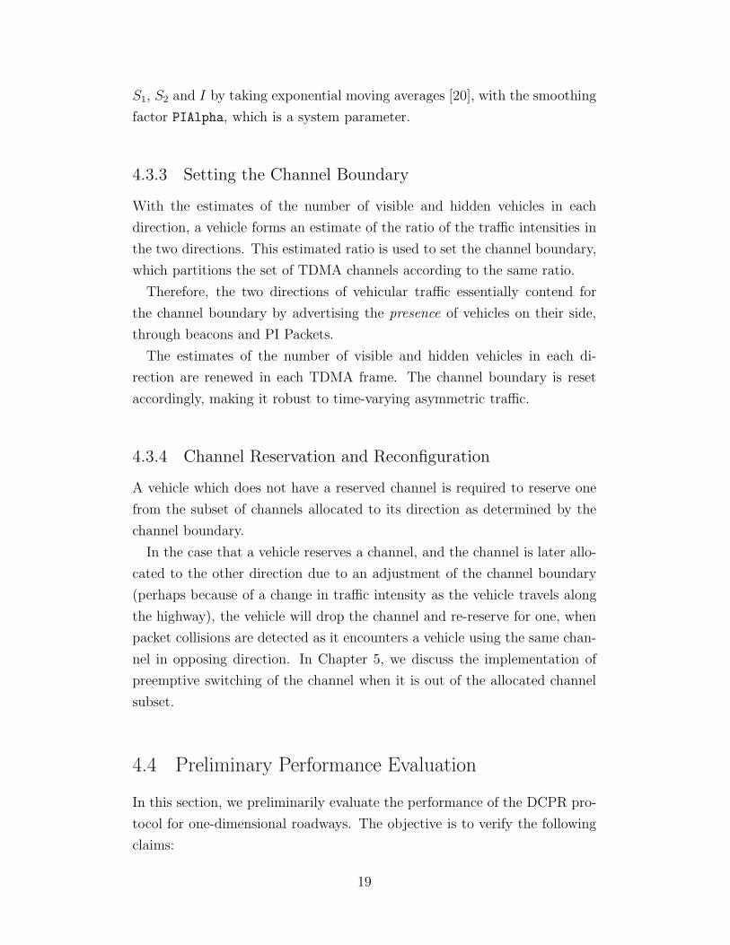
Figure 4.4: DCPR performance vis-a-vis aggregate goodput.
we add the feature that the MAC layer drops any outdated beacon if there is
a fresher beacon waiting to be transmitted in the interface queue. In DCPR
and DCPR/SCP, the MAC layer drops beacons when a TDMA channel has
not been reserved. At the physical layer, the transmission range of vehicles
is set to 368m, and the data rate is set to 3Mbps. Radio propagation is
simulated by the Two-ray Ground Reflection Model.
The simulation for each scenario is run for 60 seconds.
4.4.1 Goodput
We first study the goodput performance of the three protocols. Aggregate
goodput is the total amount of application payload received by all vehicles in
the network divided by the simulation time. Figure 4.4 plots the aggregate
goodput achieved by the three protocols, versus the ratio of traffic intensities
in the two directions.
First, DCPR outperforms IEEE 802.11p in goodput by 21%, averaged
across all scenarios. DCPR achieves a higher goodput because it exploits the
structures of VANETs, and uses TDMA to support periodic broadcasting,
such that beacons are transmitted in reserved channels, which are collision-
free. In contrast, IEEE 802.11p uses CSMA/CA for broadcast. Each beacon
transmitted is subjected to potential collisions, the chance of which is higher
in broadcast, since no RTS/CTS handshake is performed, and the contention
window size is not adjusted in response to network congestion [16].
Another important observation is that the goodput achieved by DCPR/SCP
decreases with asymmetry of traffic intensities in the two directions, while
21
5:5 6:4 7:3 8:2 9:1 10:00
5
10
15
20
25
Ratio of traffic intensities in the two directions
Med
ium
acc
ess
dow
ntim
e (s
)
DCPR IDTDCPR CDTDCPR/SCP IDTDCPR/SCP CDT
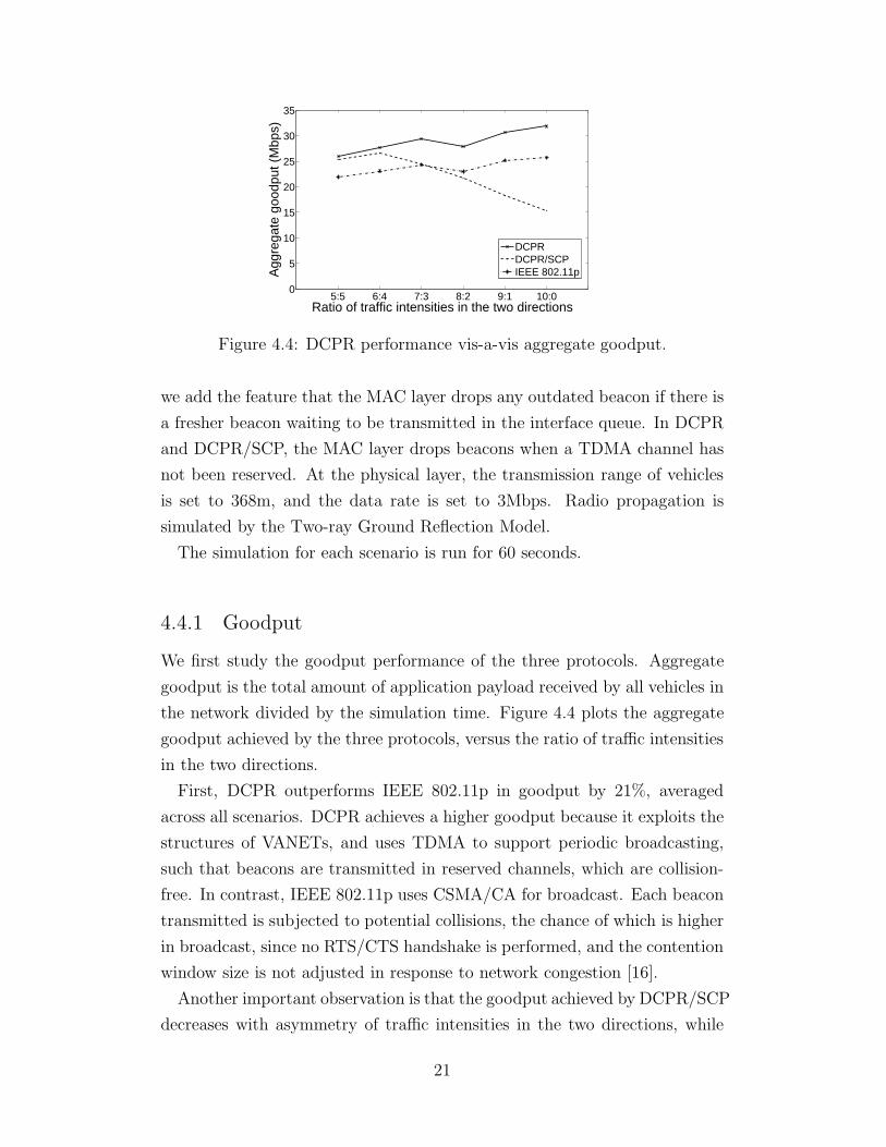
Figure 4.5: DCPR performance vis-a-vis medium access downtime pervehicle. IDT denotes initial downtime; and CDT denotes collisiondowntime.
the goodput achieved by DCPR remains stable. In particular, DCPR/SCP
suffers a 40% reduction in goodput when the traffic ratio changes from 5:5 to
10:0. This shows that the Dynamic Channel Partition Mechanism of DCPR
does succeed in allocating TDMA channels to the two directions according
to their asymmetric demands, and vehicles in both directions succeed in re-
serving a channel for their transmissions of beacons. For DCPR/SCP, the
static half-and-half channel partition scheme does not allocate channels ac-
cording to asymmetric demands. The result is that some vehicles on the side
with dense traffic fail to secure a channel to transmit beacons, leading to a
decrease in goodput achieved.
We observe that there are fluctuations in the goodput achieved by DCPR
and IEEE 802.11p at different asymmetry levels. Since they show the same
trend, they are likely caused by fluctuations in vehicle density at different
traffic asymmetry levels, which we cannot keep absolutely constant due to the
complications with the Intelligent Driver Model used to simulate vehicular
mobility.
4.4.2 Medium Access Downtime
For DCPR and DCPR/SCP, we further study their medium access downtime,
which is the period when a vehicle does not have a reserved channel, and is
unable to transmit beacons. This situation occurs when a vehicle is initially
probing to reserve a channel, and when a vehicle surrenders its reserved
22
channel due to detected packet loss that is caused by encountering another
vehicle using the same channel in its vicinity. The downtime due to the
former reason is called initial downtime, while the downtime due to the latter
reason is called collision downtime. Figure 4.5 plots the initial and collision
downtimes per vehicle for the two protocols. The means over values measured
at all vehicles are plotted, together with the corresponding 95% confidence
intervals.
The results show that the downtimes for DCPR remain small and stable
across all levels of traffic asymmetry. The average initial downtime and
collision downtime are 0.69s and 0.39s, respectively. For DCPR/SCP, both
initial and collision downtimes increase with traffic asymmetry. Notably, as
the level of asymmetry changes from 5:5 to 10:0, the mean initial downtime
increases by a factor of 15 from 1.38s to 20.12s, out of 60s of simulation time.
In fact, in the scenario with a traffic ratio of 10:0, 23.23% of vehicles fail to
reserve a channel during the entire run of the simulation. The problem is
caused by the static half-and-half channel partition scheme of DCPR/SCP,
which always allocates half of the channels to vehicles in one direction, and
the other half of the channels to vehicles in the opposing direction. When
traffic is asymmetric, some channels on the side with sparse traffic are wasted
with no vehicle using them, while channels for the side with dense traffic are
not adequate to support all vehicles to have a properly reserved channel
which causes no interference in their vicinity. The result is that vehicles
on the side with dense traffic spend more time in probing for an available
channel, and in the worst case, a vehicle may not find an available one. The
results show that the Dynamic Channel Partition Mechanism of DCPR is
essential for guaranteeing persistent performance gain of a VANET-specific
MAC protocol which exploits its special structures.
4.4.3 Packet Loss Rate and Beacon Interarrival Time
Next, we look at performance metrics which give insight into the reliability
of the protocols.
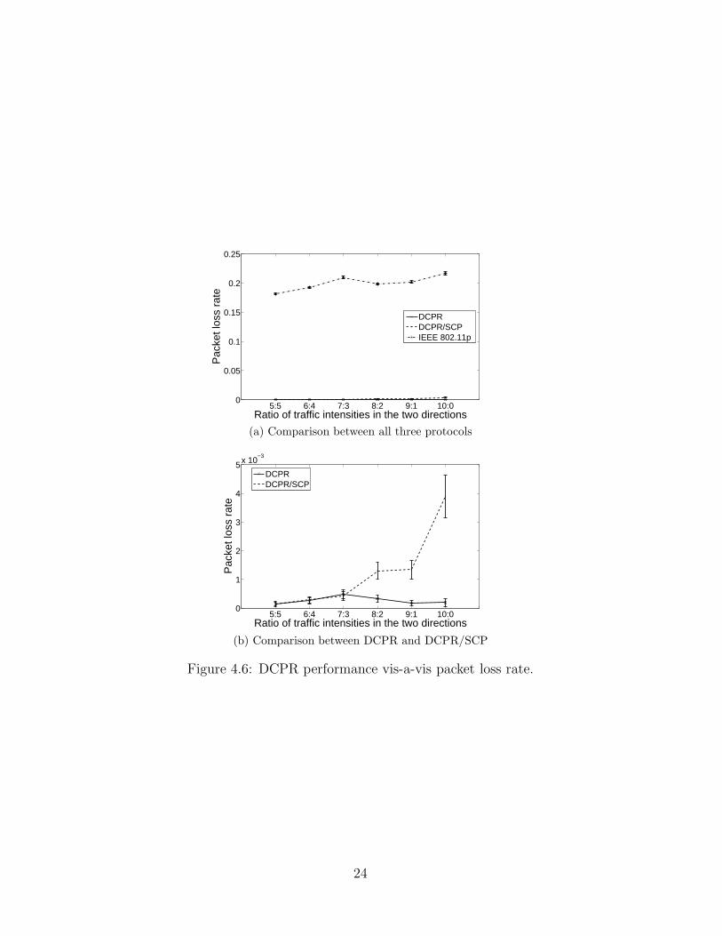
Figure 4.6 shows the packet loss rate induced by the three protocols. Each
data point is the mean of values measured over all sender-receiver pairs,
shown together with the 95% confidence intervals. The packet loss rate is
23
5:5 6:4 7:3 8:2 9:1 10:00
0.05
0.1
0.15
0.2
0.25
Ratio of traffic intensities in the two directions
Pac
ket l
oss
rate
DCPRDCPR/SCPIEEE 802.11p
(a) Comparison between all three protocols
5:5 6:4 7:3 8:2 9:1 10:00
1
2
3
4
5x 10⁻³
Ratio of traffic intensities in the two directions
Pac
ket l
oss
rate
DCPRDCPR/SCP
(b) Comparison between DCPR and DCPR/SCP
Figure 4.6: DCPR performance vis-a-vis packet loss rate.
24
the ratio of the number of beacons lost due to collisions to the total number
of beacons received at a receiver that are decodable if there is no collision.
Packet losses due to physical layer issues are not taken into account.
We observe that IEEE 802.11p results in a 20% packet loss rate on average,
while DCPR and DCPR/SCP maintain an average loss rate of 0.03% and
0.12% respectively. This is due to the different medium access schemes the
protocols employ for supporting broadcast, as mentioned previously.
DCPR/SCP suffers an increased packet loss rate by a factor of 25 as the
traffic asymmetry increases from 5:5 to 10:0, while that for DCPR remains
stable. The increased packet loss rate induced by DCPR/SCP at highly
asymmetric scenarios is due to the fact that a fixed number of channels are
shared by an increasing number of vehicles on the side with dense traffic.
This induces two phenomena: (i) Channels which are under used are more
frequently probed erroneously during the channel reservation process; and
(ii) Vehicles encounter another vehicle which shares the same channel more
frequently when they overtake. Both (i) and (ii) cause more packet collisions
and result in packet losses.
Note that although the performance of DCPR/SCP in highly asymmetric
scenarios seems to be comparable to DCPR in comparison to the performance
of IEEE 802.11p, it comes at the cost of reduced goodput and increased
downtimes, i.e., vehicles less often transmit packets into the medium. Packets
which are dropped locally at vehicles and not transmitted will not cause
packet loss in the medium, and so this performance degradation is not well
captured in the study of packet loss rate. The same is also true for the study
of beacon interarrival time, packet delay, and delay jitter below with similar
reasons.
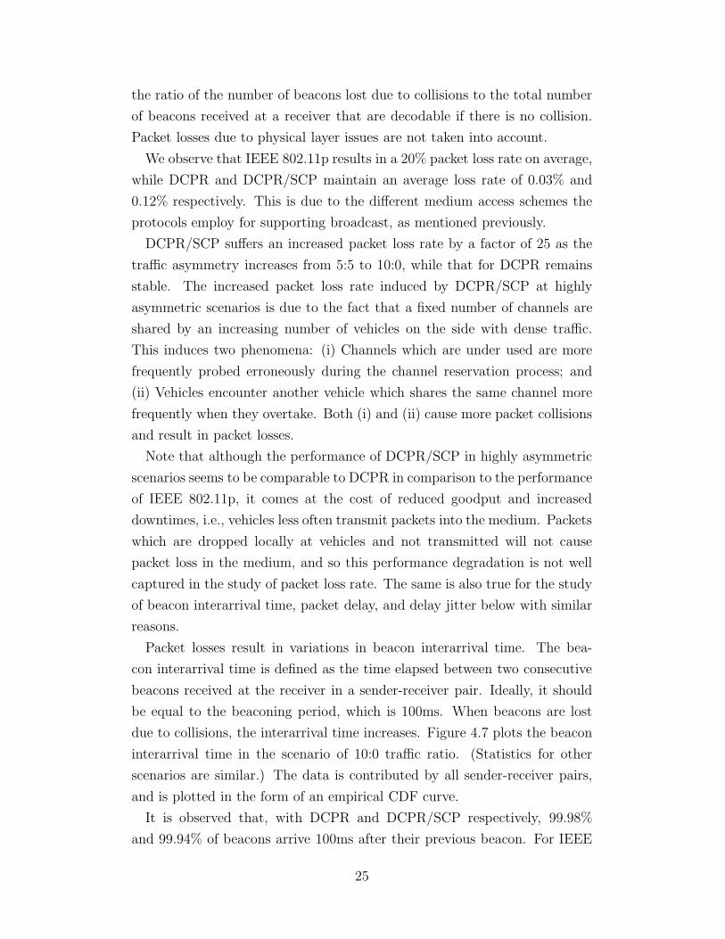
Packet losses result in variations in beacon interarrival time. The bea-
con interarrival time is defined as the time elapsed between two consecutive
beacons received at the receiver in a sender-receiver pair. Ideally, it should
be equal to the beaconing period, which is 100ms. When beacons are lost
due to collisions, the interarrival time increases. Figure 4.7 plots the beacon
interarrival time in the scenario of 10:0 traffic ratio. (Statistics for other
scenarios are similar.) The data is contributed by all sender-receiver pairs,
and is plotted in the form of an empirical CDF curve.
It is observed that, with DCPR and DCPR/SCP respectively, 99.98%
and 99.94% of beacons arrive 100ms after their previous beacon. For IEEE
25
0 0.2 0.4 0.6 0.8 10
0.2
0.4
0.6
0.8
1Empirical CDF of beacon interarrival time
x (beacon interarrival time (s))
F(x
)
DCPRDCPR/SCPIEEE 802.11p
Figure 4.7: DCPR performance vis-a-vis beacon interarrival time.
5:5 6:4 7:3 8:2 9:1 10:00
10
20
30
40
50
60
Ratio of traffic intensities in the two directions
Pac
ket d
elay
(m
s)
DCPRDCPR/SCPIEEE 802.11p
Figure 4.8: DCPR performance vis-a-vis packet delay.
802.11p, 87% of beacons arrive after around 100ms (0 beacon loss), 8% for
200ms (1 loss), 2% for 300ms (2 consecutive losses), and 1% for 400ms (3
consecutive losses). Consecutive packet loss is a threat to the reliability of ve-
hicular safety applications, as, during the consecutive beacon loss period, the
transmitting vehicle remains undetected, or hidden, from the receiving vehi-
cle. It is worth noting that the maximum beacon interarrival times recorded
for DCPR, DCPR/SCP, and IEEE 802.11p, which are not shown in Figure
4.7, are 34.46s, 44.10s, and 41.70s respectively.
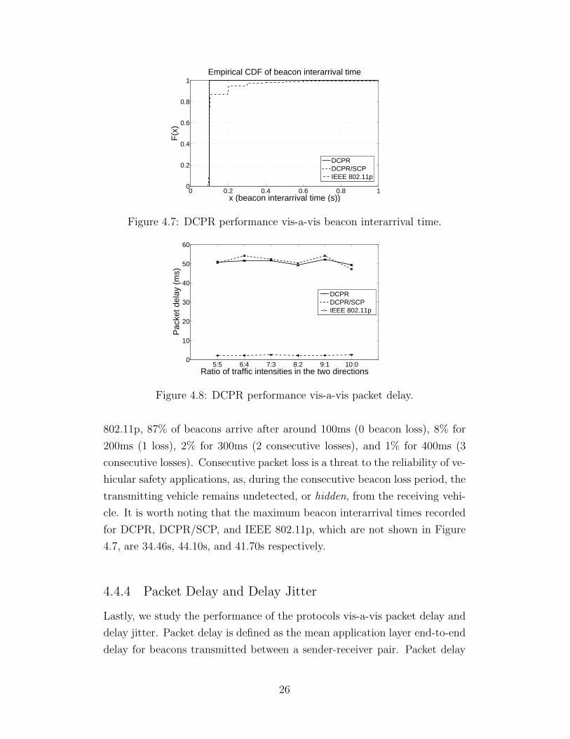
4.4.4 Packet Delay and Delay Jitter
Lastly, we study the performance of the protocols vis-a-vis packet delay and
delay jitter. Packet delay is defined as the mean application layer end-to-end
delay for beacons transmitted between a sender-receiver pair. Packet delay
26
5:5 6:4 7:3 8:2 9:1 10:00
0.5
1
1.5
2
2.5
Ratio of traffic intensities in the two directions
Pac
ket d
elay
jitte
r (m
s)
DCPRDCPR/SCPIEEE 802.11p
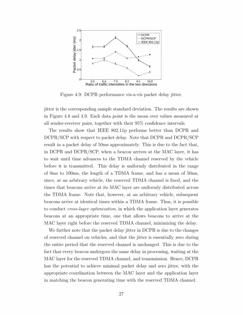
Figure 4.9: DCPR performance vis-a-vis packet delay jitter.
jitter is the corresponding sample standard deviation. The results are shown
in Figure 4.8 and 4.9. Each data point is the mean over values measured at
all sender-receiver pairs, together with their 95% confidence intervals.
The results show that IEEE 802.11p performs better than DCPR and
DCPR/SCP with respect to packet delay. Note that DCPR and DCPR/SCP
result in a packet delay of 50ms approximately. This is due to the fact that,
in DCPR and DCPR/SCP, when a beacon arrives at the MAC layer, it has
to wait until time advances to the TDMA channel reserved by the vehicle
before it is transmitted. This delay is uniformly distributed in the range
of 0ms to 100ms, the length of a TDMA frame, and has a mean of 50ms,
since, at an arbitrary vehicle, the reserved TDMA channel is fixed, and the
times that beacons arrive at its MAC layer are uniformly distributed across
the TDMA frame. Note that, however, at an arbitrary vehicle, subsequent
beacons arrive at identical times within a TDMA frame. Thus, it is possible
to conduct cross-layer optimization, in which the application layer generates
beacons at an appropriate time, one that allows beacons to arrive at the
MAC layer right before the reserved TDMA channel, minimizing the delay.
We further note that the packet delay jitter in DCPR is due to the changes
of reserved channel on vehicles, and that the jitter is essentially zero during
the entire period that the reserved channel is unchanged. This is due to the
fact that every beacon undergoes the same delay in processing, waiting at the
MAC layer for the reserved TDMA channel, and transmission. Hence, DCPR
has the potential to achieve minimal packet delay and zero jitter, with the
appropriate coordination between the MAC layer and the application layer
in matching the beacon generating time with the reserved TDMA channel.
27

CHAPTER 5
SUPPORTING VEHICULAR TRAFFIC IN
TWO-DIMENSIONAL ROAD NETWORKS
The design of DCPR developed in the previous chapters is able to support ve-
hicular traffic on a single one-dimensional roadway. It allocates TDMA chan-
nels to the two directions of traffic dynamically, so that vehicles on oppos-
ing directions do not share channels, mitigating packet collisions. However,
a complete vehicular roadway network consists of multiple roadways, net-
worked together through intersections, roundabouts, overpasses, etc. More-
over, the roadways may be curved, and may be a part of three-dimensional
structures, such as bridges and tunnels. Vehicles moving on these different
roadways, if they share common channels, will cause packet collisions also,
when they approach each other, resulting in degraded performance of the
protocol.
Hence, the DCPR protocol must be extended to support vehicular traffic
on multiple roadways in the two-dimensional and three-dimensional space to
make it a complete VANET MAC protocol. Thankfully, there are structures
of VANETs present even in the two-dimensional and three-dimensional space.
In the following, we first illustrate how these structures can be exploited
to facilitate the extension of the DCPR protocol. Then, we describe the
details of the design of the complete DCPR protocol for two-dimensional
road networks. Our current design considers two-dimensional road networks
only, but the design concept can be readily applied to extend DCPR for
supporting three-dimensional roadway structures.
28
5.1 Exploiting the Sixth Structure: Velocity—the
Differentiating Factor for Group Mobility in
Two-dimensional Road Networks
In the case of one-dimensional roadways, we have observed that if we can
divide the vehicles into two groups according to their direction of movement,
and partition the TDMA channels into two groups as well, one for the use
of vehicles in each direction of movement, then we can avoid the case of
two vehicles sharing the same channel moving towards each other, suffering
packet collisions. In a two-dimensional road network, we wish to apply similar
techniques as well to improve protocol performance.
The first key observation in two-dimensional road networks is that group
mobility of vehicles still exists in this environment. On a one-dimensional
roadway, there may be only two mobility groups, one going in one direction,
and the other going in the opposite direction. If there are multiple lanes in
one direction, vehicles on one lane may go faster than vehicles on the other
lane. More than two mobility groups may exist. When we have multiple
roads, such as at an intersection, more mobility groups will appear, going
in different directions, such as north, east, south and west, and perhaps at
different speeds as well. If we consider three-dimensional structures, such as
a bridge, some vehicles will be climbing up a slope in addition to going in
a direction, and form a separate mobility group apart from other vehicles
going in the same direction.
Then the question is how we can differentiate vehicles and group them
into their mobility group accordingly. We observe that the velocity of the
vehicles is the differentiating factor. Velocity is a two-dimensional vector in a
two-dimensional space, or a three-dimensional vector in a three-dimensional
space. It expresses the rate of change of the position of a vehicle in the
x-, y- and z-axis. Hence, it encompasses information of both the direction
and speed of a moving vehicle, and the rate of ascending or descending if
it is moving on a three-dimensional road structure. If vehicles are traveling
with similar velocities in a road network, they move together with similar
directions, speeds, and rates of ascending or descending. Hence, their relative
positions do not change rapidly. Most likely, they are traveling on the same
lane of a road and form a mobility group, or traveling on adjacent lanes or
29

roads which happen to have the same velocity.
As long as vehicles travel with similar velocities, their relative positions do
not rapidly change, no matter whether they travel on the same roadway, or
on adjacent roadways. Then, if an initial assignment of TDMA channels to
these vehicles moving in a group does not cause packet collisions at the time
the channels are reserved (because of reusing channels at proper spatial sep-
arations), then this assignment will not cause packet collisions thereafter as
the vehicles subsequently move along together. Hence, vehicles in a mobility
group can share a group of TDMA channels, just as vehicles moving in the
same direction on a one-dimensional roadway can share a group of TDMA
channels.
For vehicles traveling with velocities with large differences, they do not
move together and experience rapid change in the network topology they
form. If they share common TDMA channels, vehicles sharing the same
channel may approach each other in the road network, and suffer packet
collisions. Thus, they have to use different groups of TDMA channels, just
as vehicles moving in opposing directions on a one-dimensional roadway have
to use different groups of channels.
Hence, we can develop a two-dimensional (or three-dimensional) extension
of the Dynamic Channel Partition Mechanism of DCPR that allocates a
disjoint subset of TDMA channels to each mobility group of vehicles, which
is formed based on their velocities. In this way, vehicles within a mobility
group may share common TDMA channels, and reuse them spatially, while
vehicles across different mobility groups will not share channels, mitigating
packet collisions.
5.2 Exploiting the Seventh Structure: Reducibility of
Two-dimensional Vehicular Velocity in Road
Networks
After we have classified vehicles in a road network into different mobility
groups according to their velocities, the challenge is how we can map the
mobility groups onto the space of TDMA channels, so that each group will
be allocated a subset of TDMA channels. The problem is simple in the case of
30
a one-dimensional roadway, when there are only two mobility groups, one for
each direction of movement. The two mobility groups can be trivially mapped
to the two partitions, which are divided by a single channel boundary on the
linearly ordered TDMA channel space, according to a predefined order, such
as that the west direction occupies channels with lower indices, while the east
direction occupies channels with higher indices. With two-dimensional road
networks, there are multiple mobility groups with no trivial order, making
the problem more complicated.
There are multiple solutions to this problem, but we seek a solution which
satisfies the following two requirements. First, we want to find a distributed
solution, in order to maintain the distributed nature of vehicular networks.
Hence, solutions which employ authorities, such as roadside units, to decide
the mapping of mobility groups onto channel space in a centralized fashion
are not considered. We also avoid solutions which require high communi-
cation overhead between nodes. Hence, a solution based on clustering of
vehicles according to their velocities is not considered, since the formation
and maintenance of vehicle clusters may involve heavy communication be-
tween vehicles.
Second, the solution should result in mapping that is universal in the entire
road network, i.e., mobility groups with similar velocities spread around the
entire road network should be mapped onto similar subsets of channels in
the TDMA channel space. This property ensures that when mobility groups
move around in the road network, their allocated channels will not be in
conflict with channels of other mobility groups with different velocities, since
the mapping is universal in the entire road network.
To satisfy the two requirements, we design a mechanism in which each indi-
vidual vehicle maps itself onto the TDMA channel space according to its own
velocity. Since vehicles in a mobility group share similar velocities, according
to the mechanism, they will all map themselves onto similar locations in the
TDMA channel space. Moreover, this mapping will be universal across the
whole road network, as the same mechanism is used by every vehicle in the
road network.
However, the problem of mapping vehicles according to their velocity onto
the TDMA channel space is difficult, as the velocity space is two-dimensional,
while the TDMA channel space is one-dimensional. As we map individual
vehicles onto the channel space according to their velocity, we hope that
31
dy/dt
dx/dt
(a) The velocities do not spreadacross the entire two-dimensionalspace as depicted.
dy/dt
dx/dt
(b) Instead, the velocities lie onthe directions of roadways.
Figure 5.1: Vehicular velocities in a road network.
vehicles with similar velocities, which correspond to a mobility group, are
mapped onto adjacent channels in the TDMA channel space. Yet, it is hard
to find a mapping from the two-dimensional velocity space onto the one-
dimensional TDMA channel space with such a property.
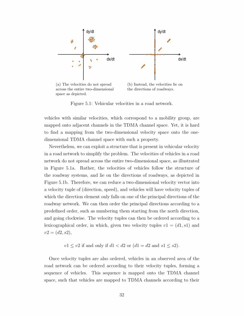
Nevertheless, we can exploit a structure that is present in vehicular velocity
in a road network to simplify the problem. The velocities of vehicles in a road
network do not spread across the entire two-dimensional space, as illustrated
in Figure 5.1a. Rather, the velocities of vehicles follow the structure of
the roadway systems, and lie on the directions of roadways, as depicted in
Figure 5.1b. Therefore, we can reduce a two-dimensional velocity vector into
a velocity tuple of (direction, speed), and vehicles will have velocity tuples of
which the direction element only falls on one of the principal directions of the
roadway network. We can then order the principal directions according to a
predefined order, such as numbering them starting from the north direction,
and going clockwise. The velocity tuples can then be ordered according to a
lexicographical order, in which, given two velocity tuples v1 = (d1, s1) and
v2 = (d2, s2),
v1 ≤ v2 if and only if d1 < d2 or (d1 = d2 and s1 ≤ s2).
Once velocity tuples are also ordered, vehicles in an observed area of the
road network can be ordered according to their velocity tuples, forming a
sequence of vehicles. This sequence is mapped onto the TDMA channel
space, such that vehicles are mapped to TDMA channels according to their
32

1 2 3 4 5 6 7 8 9 10 11 12 13 14 15 16 17 18 19 20 21 22 23 24 25 26 27 28 29 30 31 32
(1,23) (2,41) (2,43) (2,44) (2,60) (2,62) (4,43) (4,61)
Figure 5.2: Mapping an ordered sequence of vehicles onto the TDMAchannel space. Brackets above the vehicles give the velocity tuples of thevehicles in the format of (direction, speed). As illustrated, vehicles in amobility group may share their allocated channels.
position in the sequence, as shown in Figure 5.2. Note that vehicles within
a mobility group are ordered together in this sequence and are mapped to
adjacent TDMA channels, since they have the same principal direction, and
similar speeds.
Then an individual vehicle may identify other vehicles in its mobility group,
and TDMA channels mapped to vehicles within a mobility group can be
shared among all vehicles in the group as shown in Figure 5.2. In this way,
different mobility groups occupy different sections in the TDMA channel
space, according to their velocity. The TDMA channel space can hence be
viewed as being partitioned by multiple boundaries, which are determined by
the relative sizes of the mobility groups. Disjoint subsets of TDMA channels
are hence allocated to different mobility groups. Note that as vehicles in the
entire road network use the same order on velocity tuples to map vehicles
onto the TDMA channel space, the order is universal across the road network,
while the exact mapping varies according to the relative sizes of the mobility
groups in different parts of the road network, allowing flexible use of the
TDMA channel space. An example is shown in Figure 5.3.
5.3 The Velocity Differentiated Dynamic Channel
Partition Mechanism for Two-dimensional Road
Networks
We now describe the detailed extension of the DCPR protocol in order to
support vehicular traffic in two-dimensional road networks. In particular, the
33

1
2
3
678
9
10
1
2
3
4
5
1
2
3
4
6
7
8
5
12
13
14
15
16
11
9
10
13
14
16
68
12
11
9
12
Figure 5.3: An example showing the mapping of mobility groups to TDMAchannels in different parts of the road network. Each circle represents avehicle, with the number indicating the TDMA channel the vehicle uses.Note that the mapping on the right part of the network is different fromthat on the left, where there are a high number of vehicles traveling only inthe north and south directions, and all the sixteen channels are allocated tothese two mobility groups.
34

Dynamic Channel Partition Mechanism for one-dimensional roadways is ex-
tended by partitioning the set of TDMA channels according to the velocities
of vehicles. The extended mechanism is named the Velocity Differentiated
Dynamic Channel Partition (VDDCP) Mechanism.
The extension is based on the basic DCP mechanism for one-dimensional
roadways. Like the basic mechanism, the VDDCP mechanism is distributed
among vehicles. To determine the subset of TDMA channels which are avail-
able for use, each vehicle needs to observe visible and hidden vehicles in its
vicinity, and their velocity information, to construct an order of vehicles ac-
cording to the above exposition. It then determines the subset of TDMA
channels available for use, and reserves a channel in the subset. It reconfig-
ures the reserved channel in case of disruptions.
Since each vehicle determines the subset of TDMA channels available for
use according to its local observation of vehicles, or mobility groups, in its
vicinity, the set of TDMA channels will be partitioned dynamically according
to the number of mobility groups in different parts of the road network,
together with their relative sizes.
5.3.1 Observing Visible Vehicles and Their Velocities
Visible vehicles are vehicles which have already reserved a TDMA channel
and are transmitting periodic beacons. To facilitate the exchange of velocity
information, the original Direction Bit in the DCPR protocol is extended to
two fields in the DCPR packet header, which are to store the direction and
speed information in the transmitting vehicle’s velocity tuple. A vehicle is
to piggyback its instantaneous velocity information in these two fields with
each beacon it sends. Note that the direction and speed information of a
vehicle is obtainable from its GPS and speedometer.
In our implementation, the principal directions of a road network are
quantized to be one of the major directions, such as north, northeast, and
north-northeast. The level of quantization is a tunable system parameter,
NumDirections, which divides the 360 degrees evenly. These major direc-
tions are ordered and numbered from north clockwise. The direction of a
vehicle is quantized to the nearest major direction, which helps remove the
noise in momentary changes of direction of movement, such as during lane
35
changing.
An observing vehicle processes packets received from other vehicles which
contain velocity information as follows. It classifies the transmitting vehicles
into three order groups to order the vehicles. Let vT = (dT , sT ) be the re-
ceived velocity tuple from the transmitting vehicle. Let vR = (dR, sR) be the
velocity tuple of the observing vehicle. A system parameter GMSpeedRange
is used to indicate the acceptable difference in speeds of vehicles to be con-
sidered in the same mobility group. The transmitting vehicle is classified
into
• Order Group 1, if dT < dR or (dT = dR and sT < sR − GMSpeedRange);
• Order Group 2, if dT = dR and sT ≥ sR − GMSpeedRange and sT ≤
sR + GMSpeedRange;
• Order Group 3, if dT > dR or (dT = dR and sT > sR + GMSpeedRange).
Vehicles in Order Group 2 are considered by the observing vehicle as vehicles
traveling in the same mobility group. Vehicles in Order Group 1 are vehicles
ordered before the mobility group in the lexicographical order on velocity
tuples. Vehicles in Order Group 3 are vehicles ordered after the mobility
group.
The observing vehicle updates the number of vehicles in each group in each
TDMA frame. This information is used to determine the subset of available
TDMA channels explained later.
5.3.2 Observing Hidden Vehicles and Their Velocities
Just as in the basic DCP mechanism for one-dimensional roadways, hidden
vehicles have to be taken into account when determining the subset of avail-
able TDMA channels for an observing vehicle. A hidden vehicle, which does
not have a reserved TDMA channel, is to transmit a PI Packet on the PI
Channel with probability PIProb every TDMA frame. The PI Packet also
carries the velocity tuple of the transmitting vehicle in its DCPR header.
An observing vehicle then listens on the PI Channel to estimate the number
of hidden vehicles in each order group. Similarly, it empirically estimates (i)
the probability that the PI Channel is idle, (ii) the probability that a PI
Packet is successfully received on the PI Channel from a hidden vehicle in
36

Order Group 1, (iii) the same probability for Order Group 2, and (iv) the
same probability for Order Group 3. Then, it estimates the number of hidden
vehicles in each order group according to a similar analysis as in the basic
DCP mechanism.
Let p = PIProb, the probability that a hidden vehicle transmits a PI
Packet in a TDMA frame. Let n be the total number of hidden vehicles
within the reception range of the observing vehicle, of which n1 vehicles
are traveling with a velocity in Order Group 1, and n2 and n3 vehicles for
Order Group 2 and 3 respectively. Let m be the total number of hidden
vehicles within the observing vehicle’s interference range or carrier-sensing
range. (Again, we assume they are set equal.) We can similarly derive the
following probabilities of the different statuses of the PI Channel:
1. The probability that the PI Channel is idle is
I = (1 − p)m.
2. The probabilities that a PI Packet is successfully received from a hidden
vehicle in Order Groups 1, 2 and 3 are, respectively,
S1 = n1p(1 − p)m−1,
S2 = n2p(1 − p)m−1,
S3 = n3p(1 − p)m−1.
Thus, the number of hidden vehicles in each order group, within the reception
range of the observing vehicle, are
n1 =S1
I(1 − p
p),
n2 =S2
I(1 − p
p),
n3 =S3
I(1 − p
p).
Hence, an observing vehicle can estimate n1, n2 and n3, the numbers of
hidden vehicles in each order group within its reception range, by empirically
estimating the probabilities S1, S2, S3 and I. We again smooth S1, S2, S3
37
and I by taking exponential moving averages [20], with the smoothing factor
PIAlpha, a system parameter.
5.3.3 Determining the Subset of TDMA Channels Available
for Use
After estimating the numbers of both visible and hidden vehicles in each
velocity order group, an observing vehicle calculates two channel boundaries
to determine the subset of TDMA channels available for use. Let C be the
total number of TDMA channels. Let N1, N2 and N3 be the total number
of vehicles in Order Groups 1, 2 and 3 respectively. The channel boundaries
bL and bR are calculated as follows:
bL = C ·N1
N1 + N2 + N3
,
bR = C ·N1 + N2
N1 + N2 + N3
.
The observing vehicle is permitted to use TDMA channels with indices in
the range [bL, bR], which are considered as channels allocated to its mobility
group.
The estimates of the number of visible and hidden vehicles are renewed in
every TDMA frame. The channel boundaries are also renewed accordingly,
making the protocol robust to time-varying vehicular traffic.
5.3.4 Channel Reservation and Reconfiguration
A vehicle which does not have a reserved channel is then to reserve a channel
within the subset of TDMA channels allocated to its mobility group.
A vehicle is required to drop its reserved channel when collisions are de-
tected on the channel.
There are cases where a channel that was reserved by a vehicle with respect
to the allocated subset of TDMA channels later falls outside its calculated
channel boundaries, as they are renewed in subsequent TDMA frames. This
can be due to a change of the vehicle’s own speed or direction, or a change
in the velocities of its surrounding vehicles. If this condition persists for
CSCOutBoundaries TDMA frames consecutively, where CSCOutBoundaries
38
is a system parameter, the vehicle is required to re-reserve another chan-
nel within the updated allocated subset of channels, while it is permitted
to continue to temporarily use the original channel, until a new channel is
successfully reserved.
39
CHAPTER 6
SUPPORTING WIRELESS FADING
CHANNELS
In this chapter, we address enhancements to the DCPR protocol in order to
ensure its proper operation in a wireless channel with fading. In a VANET
environment, fading is due to obstacles such as buildings and vehicles as
well as multi-path propagation. The radio propagation environment in real
VANETs is far from that described by the Free Space Model or the Two
Ray Ground Model, which model the reception power of a packet as a deter-
ministic function of its reception distance. The Nakagami Fading Model is
commonly accepted as a more realistic model for a PHY environment with
slow and fast fading, which models the packet reception power probabilisti-
cally according to the Nakagami distribution. In order to understand better
the performance of the DCPR protocol in a real VANET environment, we
have evaluated the unmodified DCPR with simulations using the Nakagami
Fading Model. We first establish the necessity for protocol enhancements by
showing that fading does have a severe impact on the performance of the un-
enhanced DCPR protocol, based as it is on a deterministic PHY environment
with notions of fixed reception range, interference range and carrier-sensing
range. So motivated, we discuss the design of enhancements to the DCPR
protocol for proper operation in a PHY environment with fading. Finally, by
simulation testing we show that these enhancements do significantly improve
the performance of the protocol in an environment with Nakagami fading.
In the sequel, we explain the impact of fading on the DCPR protocol, and
describe the enhancements we design. The simulation results are presented
in Chapter 7.
40
6.1 Filtering Unwanted Control Signals by Reception
Distance
In a wireless channel with fading, there is no notion of reception range. In-
stead, there is only an intended reception or communication range specified
by a protocol or an application. For example, a VANET application may
require exchange of beacons between vehicles within a communication range
of 150m. In the DCPR protocol, the intended reception range of control
signals embedded in the DCPR packet header of beacons is set to the same
distance to facilitate the intended communication range of the application.
However, due to the effect of fading on the channel, the reception of a packet
is not deterministically determined by its “reception distance.” Rather, it
is determined by whether its received power is higher than the reception
threshold of the receiving wireless device. The received power of a packet
transmitted over a distance varies according to the magnitude of fading it
experiences, and it is sometimes greater than the expected power due to con-
structive interference. So, there are occasions when a beacon which contains
control signals of the DCPR protocol is received from a distance beyond the
intended reception distance of the protocol.
This situation creates problems for the DCPR protocol since the beacons
contain signals which indicate whether a TDMA channel is available or not,
based on whether a carrier is sensed on the channel, and whether collisions
are detected on a TDMA channel or not. These are then transmitted through
the Channel Availability Bitmap and the Collision Detection Bitmap in the
DCPR packet header, inherited from the distributed dynamic TDMA mech-
anism proposed in [4, 10, 9]. However, with fading, a signal indicating a
TDMA channel being occupied may be received from a distant node, which
does not reflect the true situation in the vicinity of the receiving node, result-
ing in a originally usable TDMA channel being falsely considered unavail-
able. This reduces the transmission opportunities for vehicles and reduces
the goodput performance of the protocol.
The reverse problem with collision detection is similar. A collision signal
corresponding to a collision happening in a distant area may be received by
an unrelated vehicle, which causes it to drop its reserved TDMA channel.
The problem is worsened due to the fact that ordinary wireless devices are
not capable of differentiating between collisions and packet reception failures
41

due to insufficient received power. Hence, in the unenhanced DCPR pro-
tocol, all decoding failures of a signal with carrier being sensed are treated
as collisions, and a vehicle will consequently transmit corresponding colli-
sion detection signals in its beacons. This creates a serious problem since
a number of vehicles outside the intended reception range of a transmitting
vehicle are able to sense the carrier of the transmitted packet, but are not
able to decode the packet. In the absence of fading, they are not able to send
the collision detection signal back to the transmitter, as reception range is
symmetric. Yet, with fading, these collision signals which are false positives
are able to reach the transmitter by chance, causing the transmitter to drop
its reserved TDMA channel when there are actually no collisions of packets.
Although the problem is severe, the remedy is simple, thanks to the struc-
ture in VANET that the application payload of the beacons contains the
GPS location of the transmitting vehicle. (If not, the GPS location can be
recorded in the DCPR packet header.) A receiving vehicle can then filter
unwanted DCPR control signals by simply calculating the distance between
the sender of the signal and itself, and discarding all signals received beyond
the intended reception distance of the protocol.
6.2 More Cautious Channel Status Transitions and
Collision Detection
The base distributed dynamic TDMA mechanism of the DCPR protocol
contains two components: (i) Channel Status Classification (CSC) Mecha-
nism, and (ii) Collision Detection (CD) Mechanism. The first component
enables vehicles to classify TDMA channels as Available or Occupied in a
distributed fashion, through independent local carrier-sensing, and exchange
of channel status information through the Channel Availability Bitmap in
the DCPR header. It tells a vehicle which TDMA channel is available for
potential use. The second component enables vehicles to detect collisions
on TDMA channels it listens to, which are those it does not transmit on,
and inform each other of detected collisions through the Collision Detection
Bitmap in the DCPR header. When a vehicle finds that collisions are de-
tected by other vehicles on its reserved TDMA channel, it drops its reserved
channel to avoid packet loss.
42
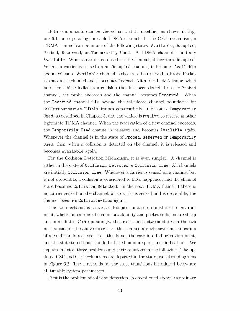
Both components can be viewed as a state machine, as shown in Fig-
ure 6.1, one operating for each TDMA channel. In the CSC mechanism, a
TDMA channel can be in one of the following states: Available, Occupied,
Probed, Reserved, or Temporarily Used. A TDMA channel is initially
Available. When a carrier is sensed on the channel, it becomes Occupied.
When no carrier is sensed on an Occupied channel, it becomes Available
again. When an Available channel is chosen to be reserved, a Probe Packet
is sent on the channel and it becomes Probed. After one TDMA frame, when
no other vehicle indicates a collision that has been detected on the Probed
channel, the probe succeeds and the channel becomes Reserved. When
the Reserved channel falls beyond the calculated channel boundaries for
CSCOutBoundaries TDMA frames consecutively, it becomes Temporarily
Used, as described in Chapter 5, and the vehicle is required to reserve another
legitimate TDMA channel. When the reservation of a new channel succeeds,
the Temporarily Used channel is released and becomes Available again.
Whenever the channel is in the state of Probed, Reserved or Temporarily
Used, then, when a collision is detected on the channel, it is released and
becomes Available again.
For the Collision Detection Mechanism, it is even simpler. A channel is
either in the state of Collision Detected or Collision-free. All channels
are initially Collision-free. Whenever a carrier is sensed on a channel but
is not decodable, a collision is considered to have happened, and the channel
state becomes Collision Detected. In the next TDMA frame, if there is
no carrier sensed on the channel, or a carrier is sensed and is decodable, the
channel becomes Collision-free again.
The two mechanisms above are designed for a deterministic PHY environ-
ment, where indications of channel availability and packet collision are sharp
and immediate. Correspondingly, the transitions between states in the two
mechanisms in the above design are thus immediate whenever an indication
of a condition is received. Yet, this is not the case in a fading environment,
and the state transitions should be based on more persistent indications. We
explain in detail three problems and their solutions in the following. The up-
dated CSC and CD mechanisms are depicted in the state transition diagrams
in Figure 6.2. The thresholds for the state transitions introduced below are
all tunable system parameters.
First is the problem of collision detection. As mentioned above, an ordinary
43
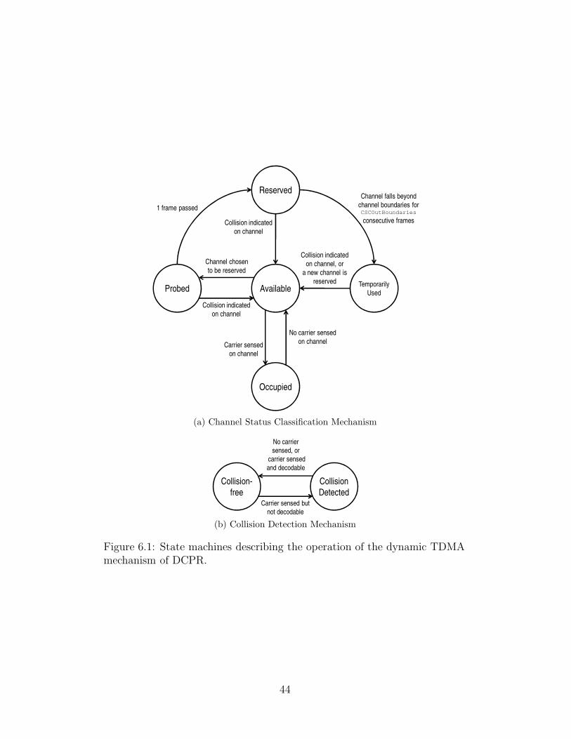
Probed Available
Reserved
Occupied
Temporarily
Used
Carrier sensed
on channel
No carrier sensed
on channel
Channel chosen
to be reserved
1 frame passed
Collision indicated
on channel
Collision indicated
on channel, or
a new channel is
reserved
Collision indicated
on channel
Channel falls beyond
channel boundaries for CSCOutBoundaries
consecutive frames
(a) Channel Status Classification Mechanism
Collision-
free
Collision
Detected
No carrier
sensed, or
carrier sensed
and decodable
Carrier sensed but
not decodable
(b) Collision Detection Mechanism
Figure 6.1: State machines describing the operation of the dynamic TDMAmechanism of DCPR.
44
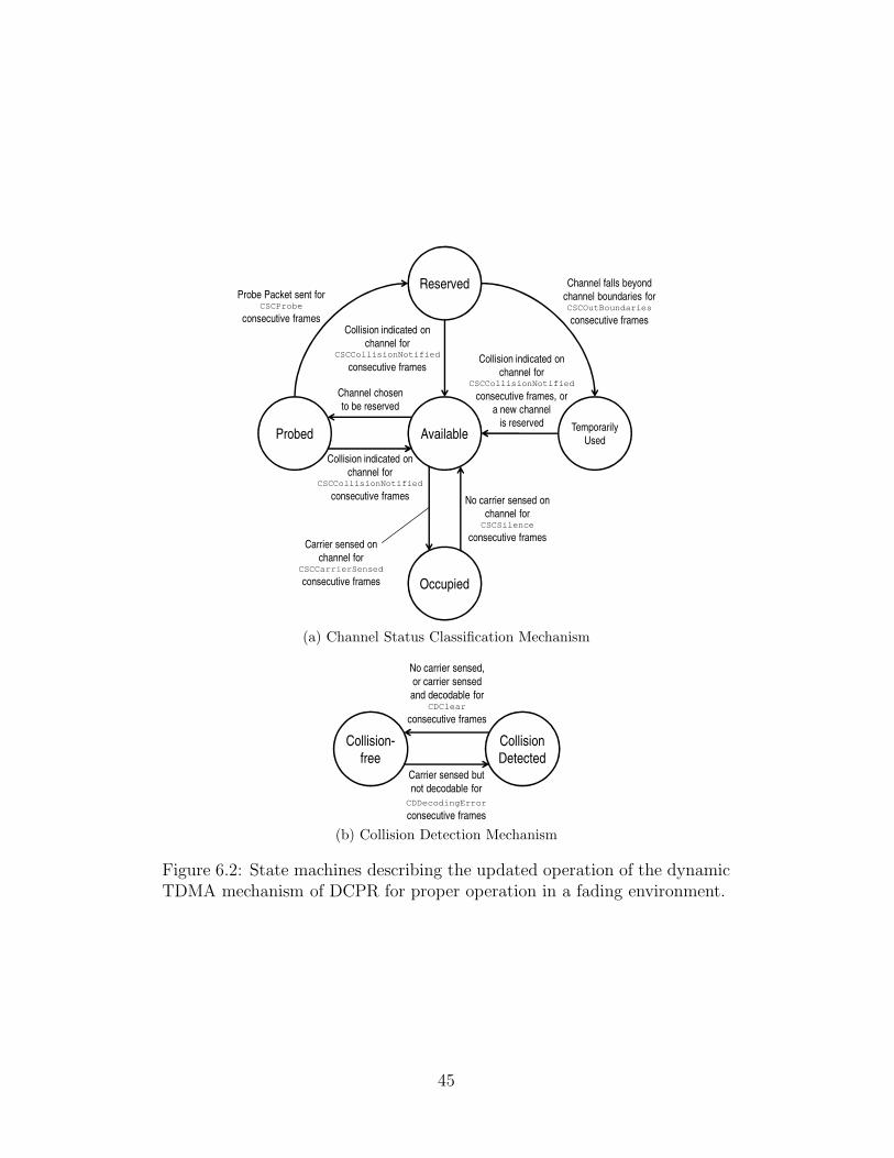
Probed Available
Reserved
Occupied
Temporarily
Used
Carrier sensed on
channel for CSCCarrierSensed
consecutive frames
No carrier sensed on
channel for CSCSilence
consecutive frames
Channel chosen
to be reserved
Probe Packet sent for CSCProbe
consecutive frames
Channel falls beyond
channel boundaries for CSCOutBoundaries
consecutive frames
Collision indicated on
channel for CSCCollisionNotified
consecutive frames
Collision indicated on
channel for CSCCollisionNotified
consecutive frames, or
a new channel
is reserved
Collision indicated on
channel for CSCCollisionNotified
consecutive frames
(a) Channel Status Classification Mechanism
Collision-
free
Collision
Detected
No carrier sensed,
or carrier sensed
and decodable for CDClear
consecutive frames
Carrier sensed but
not decodable for
CDDecodingError
consecutive frames
(b) Collision Detection Mechanism
Figure 6.2: State machines describing the updated operation of the dynamicTDMA mechanism of DCPR for proper operation in a fading environment.
45
wireless device is not capable of differentiating between packet collisions and
decoding errors due to insufficient received power. In a fading environment,
a vehicle within the intended reception range of a transmitting vehicle will
occasionally fail to receive a transmitted packet due to insufficient received
power caused by fading. If it considers the decoding failure as a collision
and immediately notifies the transmitting vehicle, it will cause the transmit-
ting vehicle to unnecessarily drop its reserved channel, causing degradation
in goodput performance of the protocol. A collision situation is more likely
when packet decoding error persists for multiple TDMA frames. Hence, a
sequence of consecutive packet decoding errors may be a more appropriate
indication for a collision situation. On the other hand, in a situation where
two vehicles do use the same TDMA channel without proper spatial sepa-
ration between them, causing a collision condition, a receiving vehicle may
not encounter continuous packet decoding errors, due to occasional packet
capture when the received power of one packet is high enough compared to
that of the other packet, both of which depend on the magnitude of fading
they encounter.
Hence, as a solution we set up counters for the state transitions in the
Collision Detection Mechanism, and also in the Channel Status Classifica-
tion Mechanism. In the CD mechanism, when a channel is in the state of
Collision-free, it transits to the Collision Detected state only when de-
coding errors are encountered for a number of CDDecodingError consecutive
TDMA frames. Similarly, the channel transits back to the Collision-free
state only when no carrier is sensed on the channel, or a carrier is sensed
and decoded for a number of CDClear consecutive frames. In the CSC mech-
anism, a Probed, Reserved or Temporarily Used channel is released and
transits to the Available state only when a vehicle receives collision de-
tection notifications for that channel from other vehicles for a number of
CSCCollisionNotified consecutive TDMA frames.
With the change in the CD and CSC mechanism, a collision takes
(CDDecodingError+CSCCollisionNotified−1) TDMA frames for it to be
confirmed at the corresponding transmitting vehicle. Therefore, when a vehi-
cle reserves a channel by sending a Probe Packet, if it causes packet collisions
at other vehicles, it will take the above amount of time for it to be confirmed.
Hence, the channel reservation process should require a vehicle to transmit
Probe Packets for at least (CDDecodingError+CSCCollisionNotified−1)
46
TDMA frames, to confirm that its use of the channel does not cause packet
collisions in its vicinity. To facilitate this, a counter is set up in the CSC
mechanism for the state transition from the Probed state to the Reserved
state of a channel, which requires Probe Packets being sent for a number of
CSCProbe consecutive frames.
Last, the classification of a channel being occupied also creates a situation
similar to collision detection. A channel should be classified as Occupied
when a vehicle is using the channel within the intended carrier-sensing range
of a receiving vehicle, as the expected power of its transmission signal will
be high enough to interfere with packet reception from other vehicles trans-
mitting on the same channel. However, when a carrier is being sensed on
a channel, it may not mean that a vehicle is transmitting within the in-
tended carrier-sensing range of the receiving vehicle, as its received power
may be increased due to fading. Conversely, when a carrier is not sensed
on an Occupied channel for one TDMA frame, it may not mean that the
channel is not used within the intended carrier-sensing range anymore, as
fading may have attenuated the power of a signal seen at the receiver. Thus,
we again add counters in the CSC mechanism for the transitions between
the Available and Occupied states. An Available channel transits to the
Occupied state only after a carrier is sensed on the channel for a number of
CSCCarrierSensed consecutive TDMA frames. An Occupied channel tran-
sits to the Available state only after carrier is not sensed on the channel for
a number of CSCSilence consecutive frames.
6.3 Dynamic Channel Probing Probability
To enable a more efficient channel reservation process, particularly when a ve-
hicle probing for a channel is required to probe for CSCProbe TDMA frames,
we further enhance the DCPR protocol with a dynamic channel probing prob-
ability, which is the probability that a vehicle without a reserved channel (a
hidden vehicle) probes for an available channel within its channel boundaries.
In the unenhanced version of the protocol, a hidden vehicle always picks one
of the available channels to probe in a TDMA frame. When the number of
hidden vehicles is high, this may produce excessive collisions and hence reser-
vation failures in the reservation process. Our enhancement is that a hidden
47
vehicle is required to estimate the number of hidden vehicles in Order Group
1 in its channel reuse range, which is the intended reception range plus the
intended carrier-sensing range, and set the probing probability to be the re-
ciprocal of that number, or the reciprocal of the number of available channels
within its channel boundaries, whichever is smaller. This enhances the like-
lihood that only one vehicle is probing a channel at a time within a channel
reuse range, and that available channels are evenly probed. The measure-
ment on the Presence Indication Channel gives an estimate of the number of
hidden vehicles in Order Group 1 within a vehicle’s reception range, which
is, n1 as denoted in Chapter 5. To estimate the number of hidden vehicles
in Order Group 1 in the vehicle’s channel reuse range, n1 is multiplied by a
system parameter, CRRFactor, which can be empirically optimized for dif-
ferent environments for best protocol performance. Let rR be the intended
reception range, and rCS be the intended carrier-sensing range. In a rural
highway environment where traffic is mainly one-dimensional, the CRRFactor
should be close to (rR + rCS)/rR. In an urban environment, where traffic is
more two-dimensional or even three-dimensional, the CRRFactor should fall
in the range between (rR + rCS)/rR and ((rR + rCS)/rR)3.
48

CHAPTER 7
PERFORMANCE EVALUATION
In this chapter, we evaluate the performance of the complete DCPR protocol
for two-dimensional road networks. Our objectives are the following:
1. To compare the performance of DCPR with different protocols, includ-
ing IEEE 802.11p, and a basic dynamic TDMA scheme;
2. To study the performance of DCPR in environments with different
vehicular traffic dynamics;
3. To evaluate DCPR in a PHY environment with fading;
4. To conduct a stress test on DCPR to see its behavior in the face of
increasing network traffic load;
5. To evaluate the sensitivity of DCPR with respect to timing errors.
We therefore conduct simulations of four different protocols. The first one
is the complete DCPR protocol for two-dimensional road networks. The
second is the DCPR protocol with the VDDCP mechanism turned off, in
which vehicles are free to use any available TDMA channel regardless of
their velocity. This is to evaluate the impact of the Velocity Differentiated
Dynamic Channel Partition Mechanism to the performance of DCPR. This
protocol is hereafter denoted as “DCPR/VDDCP Off”. The third one is
a basic dynamic TDMA scheme, which is emulated by the DCPR protocol
with both the VDDCP mechanism and the enhancements for wireless fading
channels disabled. It is hereafter called “DTDMA”. The last is the IEEE
802.11p protocol.
We evaluate these protocols in three different traffic environments. The
first scenario is a straight two-way highway, with a length of 4212m, and 12
lanes in each direction. The second scenario is a downtown area in Chicago,
which has a roadway network in the style of a Manhattan Grid, with an area
49
of 1875m × 1875m. The third scenario is a downtown area in Boston, in
which the roadway network is more irregular. This is to evaluate DCPR’s
performance when there is vehicular traffic with higher irregularity. It also
has an area of 1875m × 1875m. The maps of the simulated areas of down-
town Chicago and Boston are obtained from the TIGER database, and are
displayed in Figure 7.1
As mentioned in Chapter 6, our goal is to better understand the perfor-
mance of the DCPR protocol in a PHY environment with fading, which is
more realistic as a VANET environment. We therefore use the Nakagami
Fading Model to model radio propagation in our network simulations. De-
tails are provided later.
To conduct a stress test in terms of network traffic load, we vary the
number of vehicles simulated in each vehicular traffic environment from 120
to 720. In the highway scenario, this corresponds to a load of 16.67% to 100%
theoretical maximum, with DCPR packet header taken into account. For the
Chicago and Boston scenarios, it is hard to define a theoretical maximum load
due to the complication in the shape of the road networks, but the simulated
areas have the same size as that of the highway scenario, yielding comparable
vehicle densities.
We also study the impact of timing errors on the DCPR protocol in a
separate set of simulations. We simulate the error in time synchronization
with the GPS signal as a uniformly distributed error in the range [−e, e],
where e varies from 0µs to 50µs in different runs of the simulation. At each
vehicle, the time boundary of each TDMA channel varies according to this
error, which is independently and identically distributed.
We use VanetMobiSim 1.1 to simulate vehicular mobility. The mobility of
vehicles is simulated by the Intelligent Driver Model with Lane Changing.
The vehicles move with a target speed uniformly distributed in the range of
40mph to 70mph, while respecting physical constraints due to the roadway
and other vehicles, as well as speed limits of different categories of roads
as specified in the TIGER maps and according to the speed limit standard
in California. In the highway scenario, vehicles travel back and forth on
the simulated highway. In the Chicago and Boston scenarios, vehicles travel
with random destinations, and traffic at all intersections is governed by traffic
lights.
50

(a) Chicago
(b) Boston
Figure 7.1: Maps of the simulated areas of downtown Chicago and Boston.
51
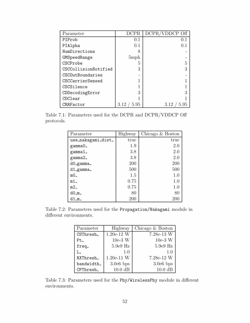
Parameter DCPR DCPR/VDDCP OffPIProb 0.1 0.1PIAlpha 0.1 0.1NumDirections 8 -GMSpeedRange 5mph -CSCProbe 5 5CSCCollisionNotified 3 3CSCOutBoundaries - -CSCCarrierSensed 1 1CSCSilence 1 1CDDecodingError 3 3CDClear 1 1CRRFactor 3.12 / 5.95 3.12 / 5.95
Table 7.1: Parameters used for the DCPR and DCPR/VDDCP Offprotocols.
Parameter Highway Chicago & Bostonuse nakagami dist true truegamma0 1.9 2.0gamma1 3.8 2.0gamma2 3.8 2.0d0 gamma 200 200d1 gamma 500 500m0 1.5 1.0m1 0.75 1.0m2 0.75 1.0d0 m 80 80d1 m 200 200
Table 7.2: Parameters used for the Propagation/Nakagami module indifferent environments.
Parameter Highway Chicago & BostonCSThresh 1.20e-12 W 7.28e-13 WPt 10e-3 W 10e-3 Wfreq 5.9e9 Hz 5.9e9 HzL 1.0 1.0RXThresh 1.20e-11 W 7.28e-12 Wbandwidth 3.0e6 bps 3.0e6 bpsCPThresh 10.0 dB 10.0 dB
Table 7.3: Parameters used for the Phy/WirelessPhy module in differentenvironments.
52
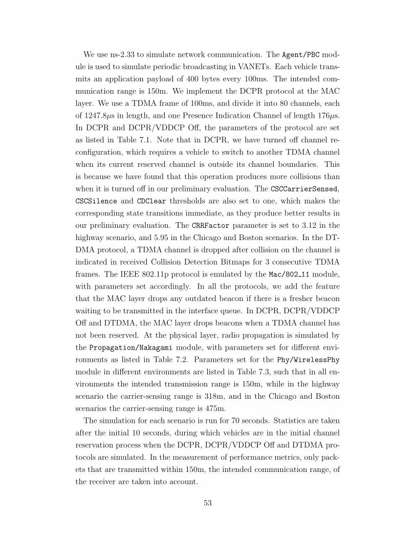
We use ns-2.33 to simulate network communication. The Agent/PBC mod-
ule is used to simulate periodic broadcasting in VANETs. Each vehicle trans-
mits an application payload of 400 bytes every 100ms. The intended com-
munication range is 150m. We implement the DCPR protocol at the MAC
layer. We use a TDMA frame of 100ms, and divide it into 80 channels, each
of 1247.8µs in length, and one Presence Indication Channel of length 176µs.
In DCPR and DCPR/VDDCP Off, the parameters of the protocol are set
as listed in Table 7.1. Note that in DCPR, we have turned off channel re-
configuration, which requires a vehicle to switch to another TDMA channel
when its current reserved channel is outside its channel boundaries. This
is because we have found that this operation produces more collisions than
when it is turned off in our preliminary evaluation. The CSCCarrierSensed,
CSCSilence and CDClear thresholds are also set to one, which makes the
corresponding state transitions immediate, as they produce better results in
our preliminary evaluation. The CRRFactor parameter is set to 3.12 in the
highway scenario, and 5.95 in the Chicago and Boston scenarios. In the DT-
DMA protocol, a TDMA channel is dropped after collision on the channel is
indicated in received Collision Detection Bitmaps for 3 consecutive TDMA
frames. The IEEE 802.11p protocol is emulated by the Mac/802 11 module,
with parameters set accordingly. In all the protocols, we add the feature
that the MAC layer drops any outdated beacon if there is a fresher beacon
waiting to be transmitted in the interface queue. In DCPR, DCPR/VDDCP
Off and DTDMA, the MAC layer drops beacons when a TDMA channel has
not been reserved. At the physical layer, radio propagation is simulated by
the Propagation/Nakagami module, with parameters set for different envi-
ronments as listed in Table 7.2. Parameters set for the Phy/WirelessPhy
module in different environments are listed in Table 7.3, such that in all en-
vironments the intended transmission range is 150m, while in the highway
scenario the carrier-sensing range is 318m, and in the Chicago and Boston
scenarios the carrier-sensing range is 475m.
The simulation for each scenario is run for 70 seconds. Statistics are taken
after the initial 10 seconds, during which vehicles are in the initial channel
reservation process when the DCPR, DCPR/VDDCP Off and DTDMA pro-
tocols are simulated. In the measurement of performance metrics, only pack-
ets that are transmitted within 150m, the intended communication range, of
the receiver are taken into account.
53
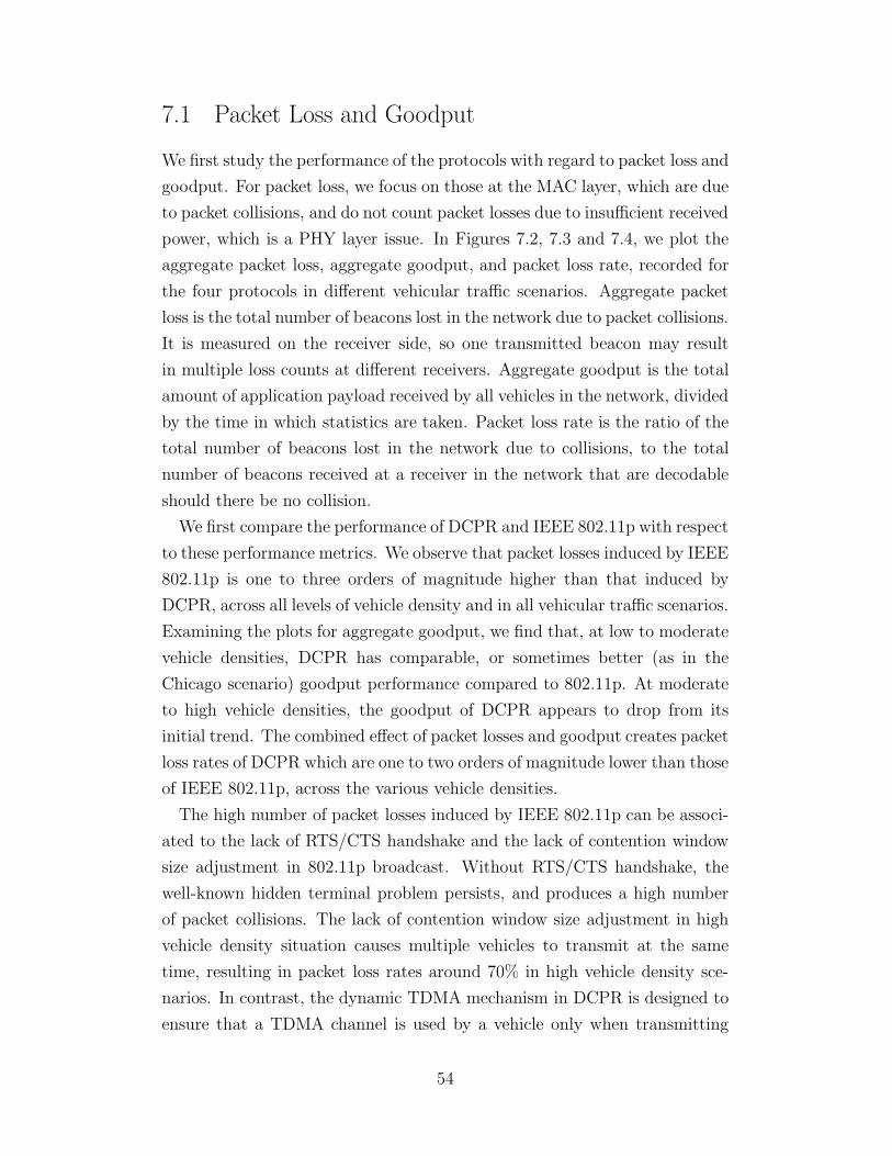
7.1 Packet Loss and Goodput
We first study the performance of the protocols with regard to packet loss and
goodput. For packet loss, we focus on those at the MAC layer, which are due
to packet collisions, and do not count packet losses due to insufficient received
power, which is a PHY layer issue. In Figures 7.2, 7.3 and 7.4, we plot the
aggregate packet loss, aggregate goodput, and packet loss rate, recorded for
the four protocols in different vehicular traffic scenarios. Aggregate packet
loss is the total number of beacons lost in the network due to packet collisions.
It is measured on the receiver side, so one transmitted beacon may result
in multiple loss counts at different receivers. Aggregate goodput is the total
amount of application payload received by all vehicles in the network, divided
by the time in which statistics are taken. Packet loss rate is the ratio of the
total number of beacons lost in the network due to collisions, to the total
number of beacons received at a receiver in the network that are decodable
should there be no collision.
We first compare the performance of DCPR and IEEE 802.11p with respect
to these performance metrics. We observe that packet losses induced by IEEE
802.11p is one to three orders of magnitude higher than that induced by
DCPR, across all levels of vehicle density and in all vehicular traffic scenarios.
Examining the plots for aggregate goodput, we find that, at low to moderate
vehicle densities, DCPR has comparable, or sometimes better (as in the
Chicago scenario) goodput performance compared to 802.11p. At moderate
to high vehicle densities, the goodput of DCPR appears to drop from its
initial trend. The combined effect of packet losses and goodput creates packet
loss rates of DCPR which are one to two orders of magnitude lower than those
of IEEE 802.11p, across the various vehicle densities.
The high number of packet losses induced by IEEE 802.11p can be associ-
ated to the lack of RTS/CTS handshake and the lack of contention window
size adjustment in 802.11p broadcast. Without RTS/CTS handshake, the
well-known hidden terminal problem persists, and produces a high number
of packet collisions. The lack of contention window size adjustment in high
vehicle density situation causes multiple vehicles to transmit at the same
time, resulting in packet loss rates around 70% in high vehicle density sce-
narios. In contrast, the dynamic TDMA mechanism in DCPR is designed to
ensure that a TDMA channel is used by a vehicle only when transmitting
54

120 240 360 480 600 72010
2
103
104
105
106
107
Number of vehicles
Agg
rega
te p
acke
t los
s
DCPRDCPR/VDDCP OffDTDMAIEEE 802.11p
(a) Highway
120 240 360 480 600 72010
2
103
104
105
106
107
Number of vehicles
Agg
rega
te p
acke
t los
s
DCPRDCPR/VDDCP OffDTDMAIEEE 802.11p
(b) Chicago
120 240 360 480 600 72010
2
103
104
105
106
107
Number of vehicles
Agg
rega
te p
acke
t los
s
DCPRDCPR/VDDCP OffDTDMAIEEE 802.11p
(c) Boston
Figure 7.2: DCPR performance vis-a-vis aggregate packet loss.
55
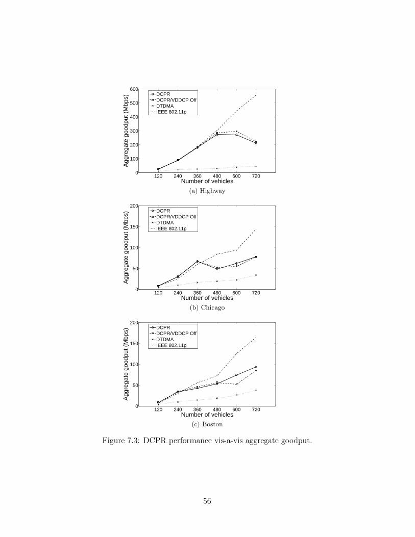
120 240 360 480 600 7200
100
200
300
400
500
600
Number of vehicles
Agg
rega
te g
oodp
ut (
Mbp
s)
DCPRDCPR/VDDCP OffDTDMAIEEE 802.11p
(a) Highway
120 240 360 480 600 7200
50
100
150
200
Number of vehicles
Agg
rega
te g
oodp
ut (
Mbp
s)
DCPRDCPR/VDDCP OffDTDMAIEEE 802.11p
(b) Chicago
120 240 360 480 600 7200
50
100
150
200
Number of vehicles
Agg
rega
te g
oodp
ut (
Mbp
s)
DCPRDCPR/VDDCP OffDTDMAIEEE 802.11p
(c) Boston
Figure 7.3: DCPR performance vis-a-vis aggregate goodput.
56
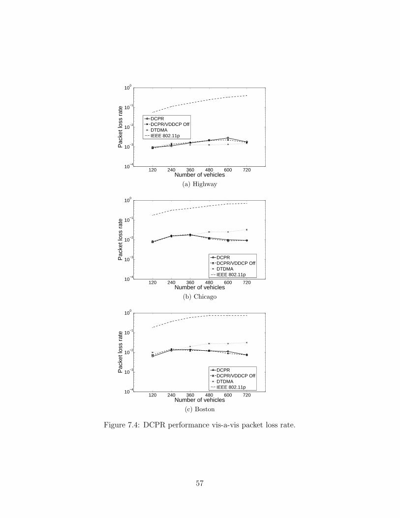
120 240 360 480 600 72010
−4
10−3
10−2
10−1
100
Number of vehicles
Pac
ket l
oss
rate
DCPRDCPR/VDDCP OffDTDMAIEEE 802.11p
(a) Highway
120 240 360 480 600 72010
−4
10−3
10−2
10−1
100
Number of vehicles
Pac
ket l
oss
rate
DCPRDCPR/VDDCP OffDTDMAIEEE 802.11p
(b) Chicago
120 240 360 480 600 72010
−4
10−3
10−2
10−1
100
Number of vehicles
Pac
ket l
oss
rate
DCPRDCPR/VDDCP OffDTDMAIEEE 802.11p
(c) Boston
Figure 7.4: DCPR performance vis-a-vis packet loss rate.
57

on it will cause no packet collisions within the intended channel reuse range,
which is the intended transmission range plus the intended carrier-sensing
range. Beacons transmitted on a reserved TDMA channel are protected
against collisions, and thus DCPR records packet loss rates around 0.1% to
1% in the various scenarios.
Although IEEE 802.11p produces excessive packet collisions in its opera-
tion, DCPR does not outperform IEEE 802.11p in goodput. We consider the
reason to be the effect of packet capture. The natures of the two protocols
are sharply different; IEEE 802.11p is aggressive in transmitting beacons,
while DCPR is very conservative. Under 802.11p, a vehicle transmits when
it does not sense a carrier within its own carrier-sensing range, while under
DCPR, a vehicle transmits only after it ensures that there is no other ve-
hicle transmitting within the carrier-sensing range of its intended receivers,
which are in turn within its intended transmission range. Hence, DCPR is
more conservative in transmission to ensure proper reception of transmit-
ted packets. Yet, due to the effect of packet capture, even when a packet
transmission results in packet collisions at some nodes which are distant from
the sender, the transmitted packet can be received at other nodes which are
close enough to the sender and have a high received power. Hence, with the
aggressive transmission scheme in 802.11p, it still produces a high amount of
goodput with the help of packet capture even when it causes a high number
of collisions at the same time.
We further note that the drop in goodput performance for DCPR at high
vehicle density scenarios may be due to a form of protocol collapse. In Figure
7.5, we plot the medium access downtime of DCPR in the different simulated
scenarios for reference. The medium access downtime is the amount of time
when a vehicle does not have a reserved TDMA channel, and thus cannot
access the medium to transmit beacons. A data point on the graph is the
mean medium access downtime of all simulated vehicles. The error bars
show one standard deviation around the mean of the metric among the ve-
hicles. We observe that the mean and standard deviation of medium access
downtime increase with vehicle density. In particular, when DCPR starts to
show a potential protocol collapse in the goodput plots, i.e., in the scenario
with 600 vehicles in the highway case, 480 vehicles in the Chicago case, and
360 vehicles in the Boston case, there are corresponding jumps in medium
access downtime. The increasing mean and standard deviation of medium
58
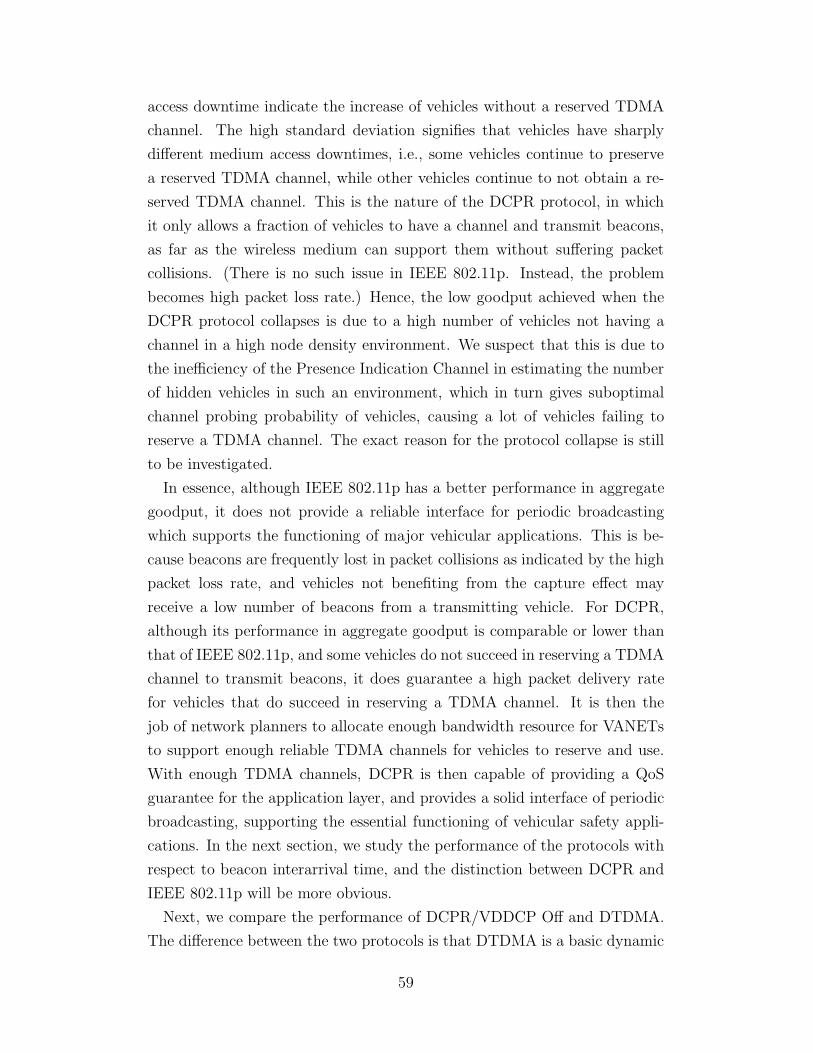
access downtime indicate the increase of vehicles without a reserved TDMA
channel. The high standard deviation signifies that vehicles have sharply
different medium access downtimes, i.e., some vehicles continue to preserve
a reserved TDMA channel, while other vehicles continue to not obtain a re-
served TDMA channel. This is the nature of the DCPR protocol, in which
it only allows a fraction of vehicles to have a channel and transmit beacons,
as far as the wireless medium can support them without suffering packet
collisions. (There is no such issue in IEEE 802.11p. Instead, the problem
becomes high packet loss rate.) Hence, the low goodput achieved when the
DCPR protocol collapses is due to a high number of vehicles not having a
channel in a high node density environment. We suspect that this is due to
the inefficiency of the Presence Indication Channel in estimating the number
of hidden vehicles in such an environment, which in turn gives suboptimal
channel probing probability of vehicles, causing a lot of vehicles failing to
reserve a TDMA channel. The exact reason for the protocol collapse is still
to be investigated.
In essence, although IEEE 802.11p has a better performance in aggregate
goodput, it does not provide a reliable interface for periodic broadcasting
which supports the functioning of major vehicular applications. This is be-
cause beacons are frequently lost in packet collisions as indicated by the high
packet loss rate, and vehicles not benefiting from the capture effect may
receive a low number of beacons from a transmitting vehicle. For DCPR,
although its performance in aggregate goodput is comparable or lower than
that of IEEE 802.11p, and some vehicles do not succeed in reserving a TDMA
channel to transmit beacons, it does guarantee a high packet delivery rate
for vehicles that do succeed in reserving a TDMA channel. It is then the
job of network planners to allocate enough bandwidth resource for VANETs
to support enough reliable TDMA channels for vehicles to reserve and use.
With enough TDMA channels, DCPR is then capable of providing a QoS
guarantee for the application layer, and provides a solid interface of periodic
broadcasting, supporting the essential functioning of vehicular safety appli-
cations. In the next section, we study the performance of the protocols with
respect to beacon interarrival time, and the distinction between DCPR and
IEEE 802.11p will be more obvious.
Next, we compare the performance of DCPR/VDDCP Off and DTDMA.
The difference between the two protocols is that DTDMA is a basic dynamic
59
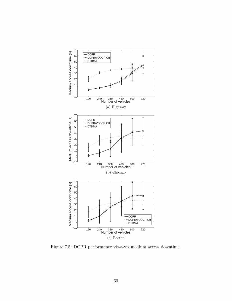
120 240 360 480 600 720−10
0
10
20
30
40
50
60
70
Number of vehicles
Med
ium
acc
ess
dow
ntim
e (s
)
DCPRDCPR/VDDCP OffDTDMA
(a) Highway
120 240 360 480 600 720−10
0
10
20
30
40
50
60
70
Number of vehicles
Med
ium
acc
ess
dow
ntim
e (s
)
DCPRDCPR/VDDCP OffDTDMA
(b) Chicago
120 240 360 480 600 720−10
0
10
20
30
40
50
60
70
Number of vehicles
Med
ium
acc
ess
dow
ntim
e (s
)
DCPRDCPR/VDDCP OffDTDMA
(c) Boston
Figure 7.5: DCPR performance vis-a-vis medium access downtime.
60
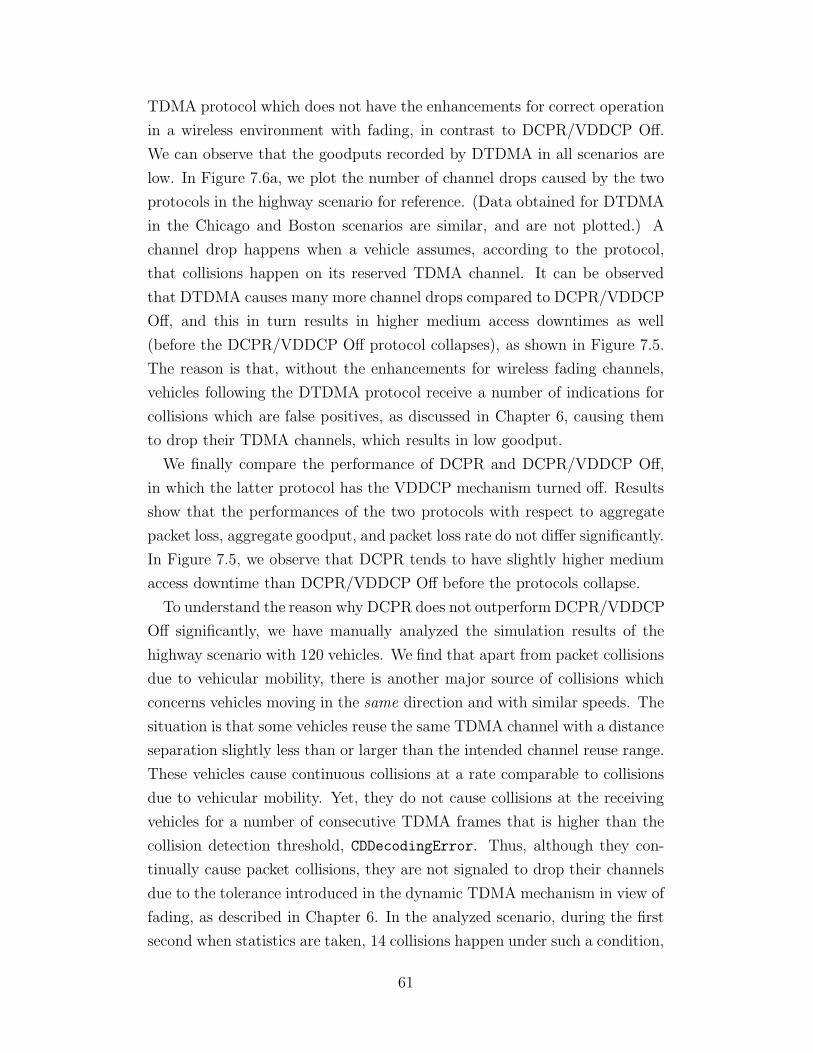
TDMA protocol which does not have the enhancements for correct operation
in a wireless environment with fading, in contrast to DCPR/VDDCP Off.
We can observe that the goodputs recorded by DTDMA in all scenarios are
low. In Figure 7.6a, we plot the number of channel drops caused by the two
protocols in the highway scenario for reference. (Data obtained for DTDMA
in the Chicago and Boston scenarios are similar, and are not plotted.) A
channel drop happens when a vehicle assumes, according to the protocol,
that collisions happen on its reserved TDMA channel. It can be observed
that DTDMA causes many more channel drops compared to DCPR/VDDCP
Off, and this in turn results in higher medium access downtimes as well
(before the DCPR/VDDCP Off protocol collapses), as shown in Figure 7.5.
The reason is that, without the enhancements for wireless fading channels,
vehicles following the DTDMA protocol receive a number of indications for
collisions which are false positives, as discussed in Chapter 6, causing them
to drop their TDMA channels, which results in low goodput.
We finally compare the performance of DCPR and DCPR/VDDCP Off,
in which the latter protocol has the VDDCP mechanism turned off. Results
show that the performances of the two protocols with respect to aggregate
packet loss, aggregate goodput, and packet loss rate do not differ significantly.
In Figure 7.5, we observe that DCPR tends to have slightly higher medium
access downtime than DCPR/VDDCP Off before the protocols collapse.
To understand the reason why DCPR does not outperform DCPR/VDDCP
Off significantly, we have manually analyzed the simulation results of the
highway scenario with 120 vehicles. We find that apart from packet collisions
due to vehicular mobility, there is another major source of collisions which
concerns vehicles moving in the same direction and with similar speeds. The
situation is that some vehicles reuse the same TDMA channel with a distance
separation slightly less than or larger than the intended channel reuse range.
These vehicles cause continuous collisions at a rate comparable to collisions
due to vehicular mobility. Yet, they do not cause collisions at the receiving
vehicles for a number of consecutive TDMA frames that is higher than the
collision detection threshold, CDDecodingError. Thus, although they con-
tinually cause packet collisions, they are not signaled to drop their channels
due to the tolerance introduced in the dynamic TDMA mechanism in view of
fading, as described in Chapter 6. In the analyzed scenario, during the first
second when statistics are taken, 14 collisions happen under such a condition,
61
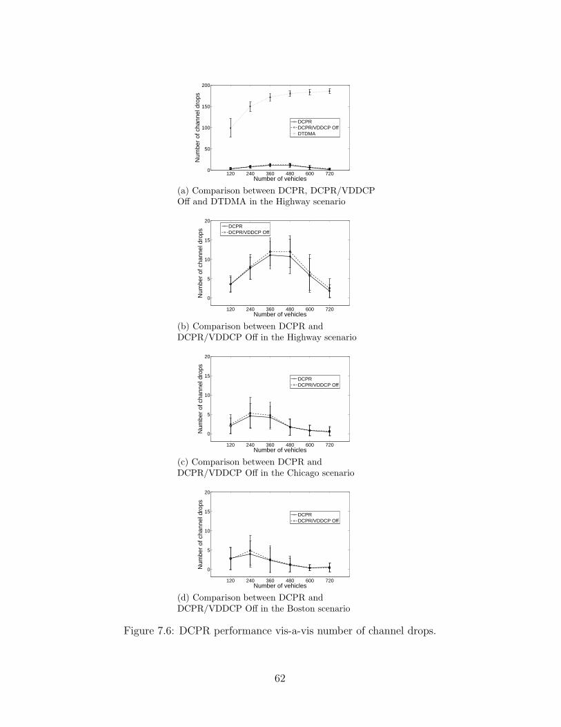
120 240 360 480 600 7200
50
100
150
200
Number of vehicles
Num
ber
of c
hann
el d
rops
DCPRDCPR/VDDCP OffDTDMA
(a) Comparison between DCPR, DCPR/VDDCPOff and DTDMA in the Highway scenario
120 240 360 480 600 720
0
5
10
15
20
Number of vehicles
Num
ber
of c
hann
el d
rops
DCPRDCPR/VDDCP Off
(b) Comparison between DCPR andDCPR/VDDCP Off in the Highway scenario
120 240 360 480 600 720
0
5
10
15
20
Number of vehicles
Num
ber
of c
hann
el d
rops
DCPRDCPR/VDDCP Off
(c) Comparison between DCPR andDCPR/VDDCP Off in the Chicago scenario
120 240 360 480 600 720
0
5
10
15
20
Number of vehicles
Num
ber
of c
hann
el d
rops
DCPRDCPR/VDDCP Off
(d) Comparison between DCPR andDCPR/VDDCP Off in the Boston scenario
Figure 7.6: DCPR performance vis-a-vis number of channel drops.
62

while 6 collisions happen due to vehicular mobility. With DCPR/VDDCP
Off, we find that there are fewer pairs of vehicles under such a condition, pos-
sibly because DCPR/VDDCP Off allows vehicles to reserve TDMA channels
in the entire set of channels, and hence vehicles in the same direction do not
reuse TDMA channels with tight distance separations. In this same first sec-
ond, there are 6 pairs of vehicles under such a condition with DCPR, while
there are 2 pairs of vehicles under such a condition with DCPR/VDDCP Off.
With this additional source of packet collisions, DCPR achieves comparable
performance with DCPR/VDDCP Off. It requires further investigation to
understand the effect of the two protocols with respect to the two sources of
packet collisions and make corresponding improvements.
Last, we add that the vehicular traffic dynamics in the highway, Chicago
and Boston scenarios are quite different. In the highway scenario, the traffic
is relatively more uniformly spread throughout the simulated area. In the
Chicago and Boston scenarios, there are areas in which the vehicular traffic
is very dense, while in the other areas the traffic is sparse, due to the char-
acteristics of the road networks. Hence, the performances of the protocols in
different vehicular traffic scenarios cannot be readily compared.
7.2 Beacon Interarrival Time
As noted in the preliminary performance evaluation in Section 4.4, packet
losses result in variations in beacon interarrival time, which is defined as
the time elapsed between two consecutive beacons received at the receiver in
a sender-receiver pair. Ideally, it should be equal to the beaconing period,
which is 100ms in our simulations. When beacons are lost due to collisions at
the MAC layer, or insufficient received power at the PHY layer, interarrival
time increases. Figure 7.7 plots the beacon interarrival time in the Chicago
scenario with 240 vehicles and 600 vehicles. The data is contributed by all
sender-receiver pairs, and is plotted in the form of an empirical CDF curve.
Note that with the metric of beacon interarrival time, packet losses due to
insufficient received power caused by fading are taken into account.
It is found that, in the 240 vehicles case, DCPR delivers 76% of beacons
around 100ms after their previous beacon, while IEEE 802.11p delivers 57%.
In the 600 vehicles case, DCPR delivers 80% and IEEE 802.11p delivers 35%
63
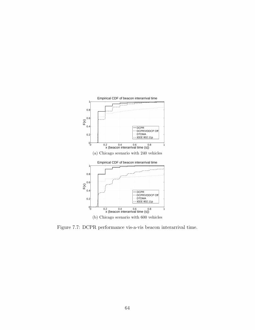
0 0.2 0.4 0.6 0.8 10
0.2
0.4
0.6
0.8
1
x (beacon interarrival time (s))
F(x
)
Empirical CDF of beacon interarrival time
DCPRDCPR/VDDCP OffDTDMAIEEE 802.11p
(a) Chicago scenario with 240 vehicles
0 0.2 0.4 0.6 0.8 10
0.2
0.4
0.6
0.8
1
x (beacon interarrival time (s))
F(x
)
Empirical CDF of beacon interarrival time
DCPRDCPR/VDDCP OffDTDMAIEEE 802.11p
(b) Chicago scenario with 600 vehicles
Figure 7.7: DCPR performance vis-a-vis beacon interarrival time.
64
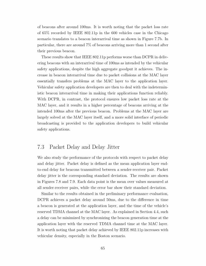
of beacons after around 100ms. It is worth noting that the packet loss rate
of 65% recorded by IEEE 802.11p in the 600 vehicles case in the Chicago
scenario translates to a beacon interarrival time as shown in Figure 7.7b. In
particular, there are around 7% of beacons arriving more than 1 second after
their previous beacon.
These results show that IEEE 802.11p performs worse than DCPR in deliv-
ering beacons with an interarrival time of 100ms as intended by the vehicular
safety applications, despite the high aggregate goodput it achieves. The in-
crease in beacon interarrival time due to packet collisions at the MAC layer
essentially transfers problems at the MAC layer to the application layer.
Vehicular safety application developers are then to deal with the indetermin-
istic beacon interarrival time in making their applications function reliably.
With DCPR, in contrast, the protocol ensures low packet loss rate at the
MAC layer, and it results in a higher percentage of beacons arriving at the
intended 100ms after the previous beacon. Problems at the MAC layer are
largely solved at the MAC layer itself, and a more solid interface of periodic
broadcasting is provided to the application developers to build vehicular
safety applications.
7.3 Packet Delay and Delay Jitter
We also study the performance of the protocols with respect to packet delay
and delay jitter. Packet delay is defined as the mean application layer end-
to-end delay for beacons transmitted between a sender-receiver pair. Packet
delay jitter is the corresponding standard deviation. The results are shown
in Figures 7.8 and 7.9. Each data point is the mean over values measured at
all sender-receiver pairs, while the error bar show their standard deviation.
Similar to the results obtained in the preliminary performance evaluation,
DCPR achieves a packet delay around 50ms, due to the difference in time
a beacon is generated at the application layer, and the time of the vehicle’s
reserved TDMA channel at the MAC layer. As explained in Section 4.4, such
a delay can be minimized by synchronizing the beacon generation time at the
application layer with the reserved TDMA channel time at the MAC layer.
It is worth noting that packet delay achieved by IEEE 802.11p increases with
vehicular density, especially in the Boston scenario.
65

120 240 360 480 600 7200
20
40
60
80
100
120
Number of vehicles
Pac
ket d
elay
(m
s)
DCPRDCPR/VDDCP OffDTDMAIEEE 802.11p
(a) Highway
120 240 360 480 600 7200
20
40
60
80
100
120
Number of vehicles
Pac
ket d
elay
(m
s)
DCPRDCPR/VDDCP OffDTDMAIEEE 802.11p
(b) Chicago
120 240 360 480 600 7200
20
40
60
80
100
120
Number of vehicles
Pac
ket d
elay
(m
s)
DCPRDCPR/VDDCP OffDTDMAIEEE 802.11p
(c) Boston
Figure 7.8: DCPR performance vis-a-vis packet delay.
66

120 240 360 480 600 720−20
0
20
40
60
80
100
Number of vehicles
Pac
ket d
elay
jitte
r (m
s)
DCPRDCPR/VDDCP OffDTDMAIEEE 802.11p
(a) Highway
120 240 360 480 600 720−20
0
20
40
60
80
100
Number of vehicles
Pac
ket d
elay
jitte
r (m
s)
DCPRDCPR/VDDCP OffDTDMAIEEE 802.11p
(b) Chicago
120 240 360 480 600 720−20
0
20
40
60
80
100
Number of vehicles
Pac
ket d
elay
jitte
r (m
s)
DCPRDCPR/VDDCP OffDTDMAIEEE 802.11p
(c) Boston
Figure 7.9: DCPR performance vis-a-vis packet delay jitter.
67

On delay jitter, we have explained in Section 4.4 that the delay jitter
recorded by DCPR is due to the changes of reserved channels on vehicles,
and that the jitter is essentially zero during the entire period that the reserved
channel is unchanged. We again note that the delay jitter achieved by IEEE
802.11p increases with vehicular density.
7.4 Sensitivity to Timing Errors
Finally, we study how sensitive the DCPR protocol is to errors in timing.
DCPR employs a dynamic TDMA mechanism at its core. Each vehicle relies
on GPS or other timing sources to synchronize its clock with the whole
system. We simulate the error in clock synchronization and study its effect
on the performance of the protocol. The simulation is conducted in the
Chicago scenario with 240 vehicles. Figure 7.10 plots the effect of timing
errors on aggregate packet loss, aggregate goodput and packet loss rate.
The results show that, as the maximum timing error increases from 0µs to
50µs, aggregate packet loss in the network increases by one order of magni-
tude. Aggregate goodput drops by 45% accordingly, and the packet loss rate
increases from 0.16% to 27%. The errors in timing significantly impacts the
performance of DCPR. This is because clock synchronization errors translate
to variations in the time boundaries of the TDMA channels among nodes.
Transmissions in two different TDMA channels may hence overlap, result-
ing in packet collisions. The high packet loss rate also means a high loss
of control information transmitted through beacons in the DCPR header,
which further degrades the performance of the protocol. Here, we note that
the problem can be relieved by inserting extra time, or guard intervals, be-
tween TDMA channels corresponding to the maximum timing error. In our
simulations, the guard interval is about 13ms, which provides tolerance to a
maximum timing error of about 6.5ms.
68
0 10 20 30 40 5010
3
104
105
106
Maximum timing error (µs)
Agg
rega
te p
acke
t los
s
(a) Aggregate packet losses
0 10 20 30 40 500
5
10
15
20
25
30
35
Maximum timing error (µs)
Agg
rega
te g
oodp
ut (
Mbp
s)
(b) Aggregate Goodput
0 10 20 30 40 500
0.05
0.1
0.15
0.2
0.25
0.3
0.35
Maximum timing error (µs)
Pac
ket l
oss
rate
(c) Packet loss rate
Figure 7.10: Sensitivity of DCPR to timing error in the 240 vehicles case inthe Chicago scenario.
69
CHAPTER 8
CONCLUDING REMARKS
In this thesis, we propose the Dynamic Channel Partition and Reservation
(DCPR) Protocol as a specific MAC protocol for vehicular networks. In the
development of DCPR, we have identified eight structures of VANETs and
TDMA which can be exploited, and have demonstrated how one can exploit
them to design a MAC protocol specifically for VANETs that attains superior
performance. In particular, we exploit (i) the periodic broadcast communica-
tion pattern of vehicular safety applications, (ii) the synchronized time made
available by GPS on vehicles, (iii) the group mobility of vehicles on a single
roadway and in a two-dimensional road network, (iv) the partition of TDMA
channels for different mobility groups according to the velocities of vehicles,
(v) the total ordering of TDMA channels, (vi) the shared frequency of TDMA
channels, (vii) the reducibility of two-dimensional vehicular velocity in road
networks, and (viii) the location of vehicles made available by GPS. With
simulations via ns-2 and VanetMobiSim, using the Intelligent Driver Model
with Lane Changing, we show that DCPR delivers significant reductions in
packet loss rate compared to IEEE 802.11p. The results also verify that en-
hancements must be made to the basic dynamic TDMA mechanism for it to
function properly in a wireless environment with fading. We also propose the
Velocity Differentiated Dynamic Channel Partition (VDDCP) Mechanism for
DCPR. Further evaluation is required to determine if there are scenarios of
vehicular traffic geometries and intensities in which DCPR with VDDCP en-
abled delivers significantly better performance than a plain DCPR protocol.
This thesis shows the possibility of building a VANET-specific MAC layer
which provides high packet delivery rate and low packet loss in support of the
development of vehicular safety applications which require high reliability.
70

REFERENCES
[1] H. Hartenstein and K. P. Laberteaux, VANET: Vehicular Applications
and Inter-Networking Technologies. Chichester, UK: John Wiley &Sons, Ltd, 2009.
[2] C. S. R. Murthy and B. Manoj, Ad Hoc Wireless Networks: Architectures
and Protocols. Upper Saddle River, NJ, USA: Prentice Hall PTR, 2004.
[3] F. Bai, H. Krishnan, V. Sadekar, G. Holl, and T. Elbatt, “Towards char-acterizing and classifying communication-based automotive applicationsfrom a wireless networking perspective,” in Proc. IEEE AutoNet 2006,2006.
[4] M. Lott, R. Halfmann, E. Schulz, and M. Radimirsch, “Medium accessand radio resource management for ad hoc networks based on UTRATDD,” in Proc. ACM MobiHoc’01, Long Beach, CA, USA, 2001.
[5] J. Yoon, M. Liu, and B. Noble, “Random waypoint considered harmful,”in Proc. IEEE INFOCOM 2003, vol. 2, Mar. 2003, pp. 1312–1321.
[6] R. K. Lam and P. R. Kumar, “Dynamic channel reservation to enhancechannel access by exploiting structure of vehicular networks,” in Proc.
IEEE VTC 2010-Spring, Taipei, Taiwan, 2010.
[7] R. K. Lam and P. R. Kumar, “Dynamic channel partition and reserva-tion for structured channel access in vehicular networks,” in Proc. ACM
VANET’10, Chicago, Illinois, USA, 2010, pp. 83–84.
[8] F. Borgonovo, A. Capone, M. Cesana, and L. Fratta, “RR-ALOHA, areliable R-ALOHA broadcast channel for ad-hoc inter-vehicle commu-nication networks,” in Proc. Med-Hoc-Net 2002, Baia Chia, Italy, 2002.
[9] F. Borgonovo, A. Capone, M. Cesana, and L. Fratta, “ADHOC MAC:New MAC architecture for ad hoc networks providing efficient and reli-able point-to-point and broadcast services,” Wireless Networks, vol. 10,no. 4, pp. 359–366, July 2004.
[10] G. Caizzone, P. Giacomazzi, L. Musumeci, and G. Verticale, “A powercontrol algorithm with high channel availability for vehicular ad hocnetworks,” in Proc. IEEE ICC 2005, vol. 5, May 2005, pp. 3171–3176.
71

[11] M. Eastwood and L. Hanzo, “Packet reservation multiple access forwireless multimedia communications,” IEE Electronic Letters, vol. 29,no. 13, pp. 1178–1180, June 1993.
[12] M. Haardt, A. Klein, R. Koehn, S. Oestreich, M. Purat, V. Sommer,and T. Ulrich, “The TD-CDMA based UTRA TDD mode,” IEEE J.
Sel. Areas Commun., vol. 18, no. 8, pp. 1375–1385, Aug. 2000.
[13] C. Eklund, R. Marks, K. Stanwood, and S. Wang, “IEEE standard802.16: a technical overview of the WirelessMAN(TM) air interface forbroadband wireless access,” IEEE Commun. Mag., vol. 40, no. 6, pp.98–107, June 2002.
[14] J. Haartsen, “The Bluetooth radio system,” IEEE Personal Commun.
Mag., vol. 7, no. 1, pp. 28–36, Feb. 2000.
[15] X. Ma and X. Chen, “Performance analysis of IEEE 802.11 broadcastscheme in ad hoc wireless LANs,” IEEE Trans. Veh. Technol., vol. 57,no. 6, pp. 3757–3768, Nov. 2008.
[16] M. Torrent-Moreno, S. Corroy, F. Schmidt-Eisenlohr, and H. Harten-stein, “IEEE 802.11-based one-hop broadcast communications: under-standing transmission success and failure under different radio propa-gation environments,” in Proc. ACM MSWiM’06, Terromolinos, Spain,2006, pp. 68–77.
[17] M. Torrent-Moreno, D. Jiang, and H. Hartenstein, “Broadcast receptionrates and effects of priority access in 802.11-based vehicular ad-hoc net-works,” in Proc. ACM VANET’04, Philadelphia, Pennsylvania, USA,Oct. 2004.
[18] N. Balon and J. Guo, “Increasing broadcast reliability in vehicular adhoc networks,” in Proc. ACM VANET’06, Los Angeles, CA, USA, 2006,pp. 104–105.
[19] C. L. Robinson, D. Caveney, L. Caminiti, G. Baliga, K. Laberteaux, andP. R. Kumar, “Efficient message composition and coding for cooperativevehicular safety applications,” IEEE Trans. Veh. Technol., vol. 56, no. 6,pp. 3244–3255, Nov. 2007.
[20] P. R. Kumar and P. Varaiya, Stochastic systems: estimation, identifica-
tion and adaptive control. Upper Saddle River, NJ, USA: Prentice-Hall,Inc., 1986.
[21] D. Jiang and L. Delgrossi, “IEEE 802.11p: Towards an internationalstandard for wireless access in vehicular environments,” in Proc. IEEE
VTC 2008-Spring, May 2008, pp. 2036–2040.
72


![Cyclic Commit Protocol Specifications · solid-state drives implemented using flash memory provide a different performance tradeoff. A cyclic commit protocol [2] exploits the advantages](https://img.pdfslide.us/doc/110x75/5f040ed47e708231d40c1c18/cyclic-commit-protocol-speciications-solid-state-drives-implemented-using-iash.jpg)