Embed Size (px)
Citation preview
DESIGN OF A CARBON FIBER BICYCLE STEM USING AN INTERNAL BLADDER AND RESIN TRANSFER MOLDING
Maxime Thouin, Larry Lessard
Department of Mechanical Engineering, McGill University, 817 Sherbrooke St. W, Montreal, Quebec, Canada H3A 2K6
ABSTRACT
The goal of this research is to design, analyze and manufacture a carbon fiber bicycle stem that maximizes the use of carbon fiber composites. The stem is the part of the bicycle that connects the handlebar to the fork. The design is difficult due to the small size and complex geometry of the part, thus not obvious to conceive with a standard composite manufacturing approach. The major problems are: the integrity of the part, the fastening method, the injection process and the post-molding operations.
This project is the result of several design iterations. Early prototypes allowed identification of the basic structural, aesthetic and manufacturing problems. In conjunction with a bicycle manufacturer, essential features (e.g., length, weight) were defined. With all the required specifications and the experience of the early prototypes, a general manufacturing plan was devised. Work began with a concurrent design and analysis process, where shapes would be designed on a 3-D CAD system and sent to finite element analysis software to find weaknesses and allow modifications. The machining and preparation of the prototyping molds followed the design stage. The molds were used to experiment with the injection and curing processes where several matrix systems were evaluated. After a limited production of prototypes, a set of jigs was designed to perform the post-machining operations and a series of tests was run to detect any possible flaws in the design. The resulting design was successful in terms of weight, stiffness, strength and aesthetic properties. Finished parts weighed below 125g and demonstrated sufficient torsion and bending stiffness values.
Even though the process is here applied to a composite part for the sports industry, the manufacturing techniques developed in this project can be applied to many other fields such as aerospace or automotive. The techniques can be used anywhere where a small, complex, hollow composite part is designed, especially where existing manufacturing methods prove difficult. KEYWORDS: bicycle stem, RTM, design, carbon braid, inner bladder, manufacturing 1. INTRODUCTION
Within the last decade, carbon fiber reinforced parts have played a major role in the improvement of sports equipment. In particular, the cycling industry has been a pioneer in developing new manufacturing methods to improve the performance of bicycles by reducing weight and improving properties [1]. However, prior to 2003, no manufacturer could build a handlebar stem (connecting the fork to the handlebar) entirely made of composite materials. This is surprising, since the stem is an important component that is subjected to high loading. Typically, racers will use their arms on the handlebars to counteract the high loads imparted to the pedals, creating an impressive amount of torque on the stem [2,3]. The stem should be stiff enough so that it has minimal deflection when the rider leans on it. Furthermore, as it is responsible for the control of the bicycle, failure of the stem must be avoided. Therefore, emphasis is placed on testing to insure high fatigue resistance.
There are several stem designs available on the market. Most of them are made of metallic alloys such as steel, aluminum or even magnesium. Their shapes and sizes are extremely diversified. The designed prototype falls into the high-end market and therefore its main competitors were identified for comparative purposes. This is how the target weight was set to 125 g for the 120mm length version. The constraints of low weight and exclusive use of carbon fiber made the project quite challenging.
Because of the tubular shape of the stem and its complex geometry, a combination of braided carbon fiber and resin transfer molding (RTM) was considered to be the most appropriate manufacturing process [4,5]. In this process, dry fabrics are inserted in a mold
cavity and a deformable membrane is used to apply a uniform pressure, pressing the material against the mold surfaces. RTM is known to be a cost effective process and is now widely used in the industry [6,7]. Moreover, the dry braided material offers a much greater drapability than the prepreg composite materials. The challenging weight requirement, the better material consolidation and the ease of manufacturing motivated the use of a removable bladder instead of a foam core [8]. Although the combined application of the RTM process and the inner bladder molding is commonly used, it still presented a difficult design challenge, considering the small size of the part. However, an important motivation to use this method is that the often-complicated handling of prepreg is replaced by the easier manipulation of dry fabrics. [5,7,9] Implementing techniques described by Michaeli et al. [5-9], a combined vent port and bladder holder was developed for the manufacturing. This technology represents the key aspect for success in production and will be described in detail.
Furthermore, the complete design process, beginning with a simultaneous modeling (CAD) and finite element stress analysis (FEA) will be discussed. This paper describes all aspects of the development such as flow modeling, manufacturing and testing.
2. DESIGN
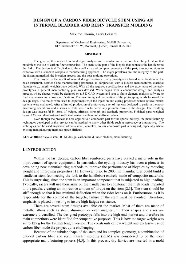
Steerer Tube Region
Handlebar Region
The handlebar cap (also called “external cap”)
Fig. 1. The general dimensions of the part (all dimensions in mm).
Fig. 1 shows the basic design of the stem, which is similar to conventional designs. The steerer clamp is closed with two M5 screws that clamp around the steerer tube. The flat regions where those fasteners are located have been integrated to the stem shape to avoid machining into the fiber after the injection. This also improves the structural integrity of the part. The handlebar clamp has threaded aluminum barrels to fix the cap over the bar. It uses four fasteners instead of the conventional two because the four-fastener configuration lowers stresses in the cap and on the tube. The stem dimensions were set by the industry standards. The handlebar clamp was made to accommodate a 31.8mm tubular section, the steerer tube is 28.6mm while the drop angle of 82 degrees was found to be the most appropriate.
The wide mouth of the handlebar clamp was designed to create a maximum of friction on the bar, thus avoiding any slipping or stress concentrations on the bar.
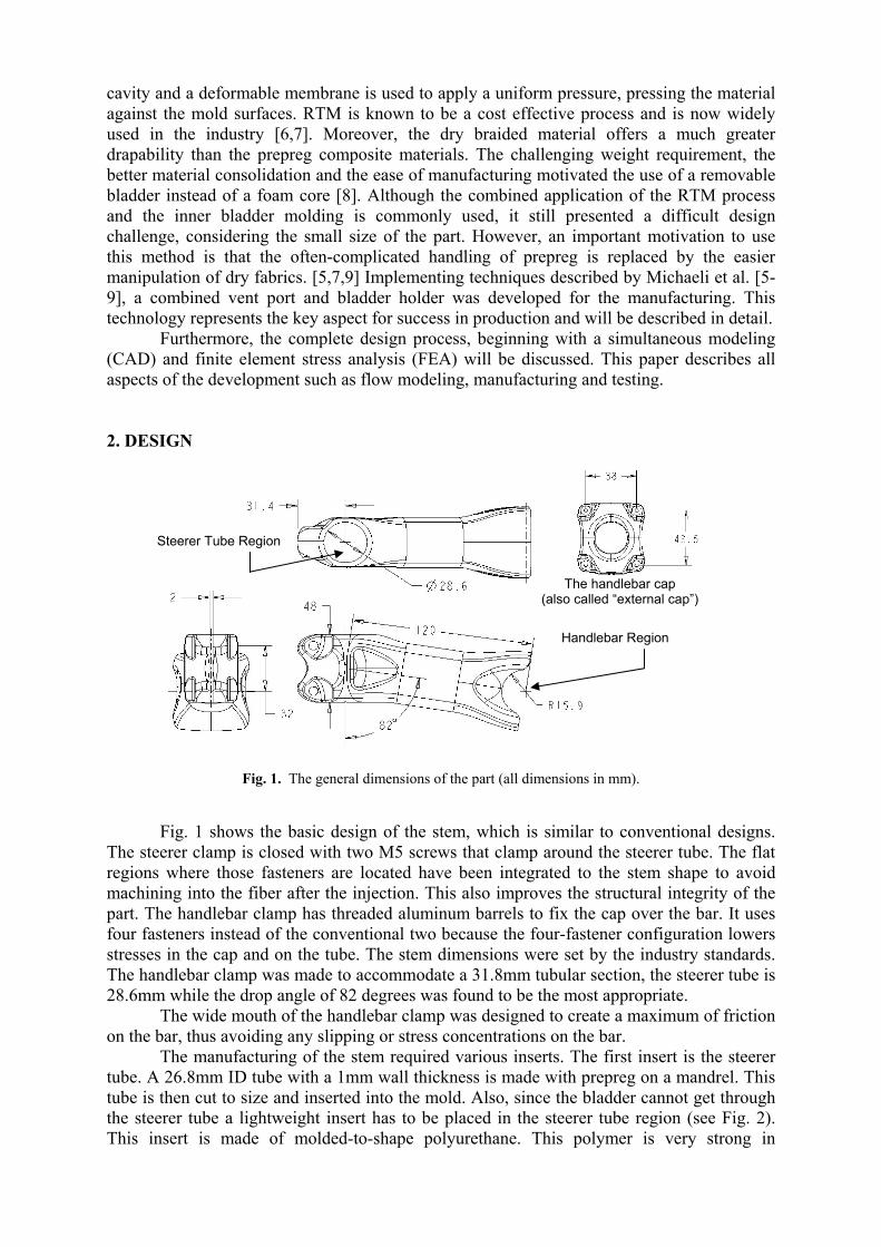
The manufacturing of the stem required various inserts. The first insert is the steerer tube. A 26.8mm ID tube with a 1mm wall thickness is made with prepreg on a mandrel. This tube is then cut to size and inserted into the mold. Also, since the bladder cannot get through the steerer tube a lightweight insert has to be placed in the steerer tube region (see Fig. 2). This insert is made of molded-to-shape polyurethane. This polymer is very strong in
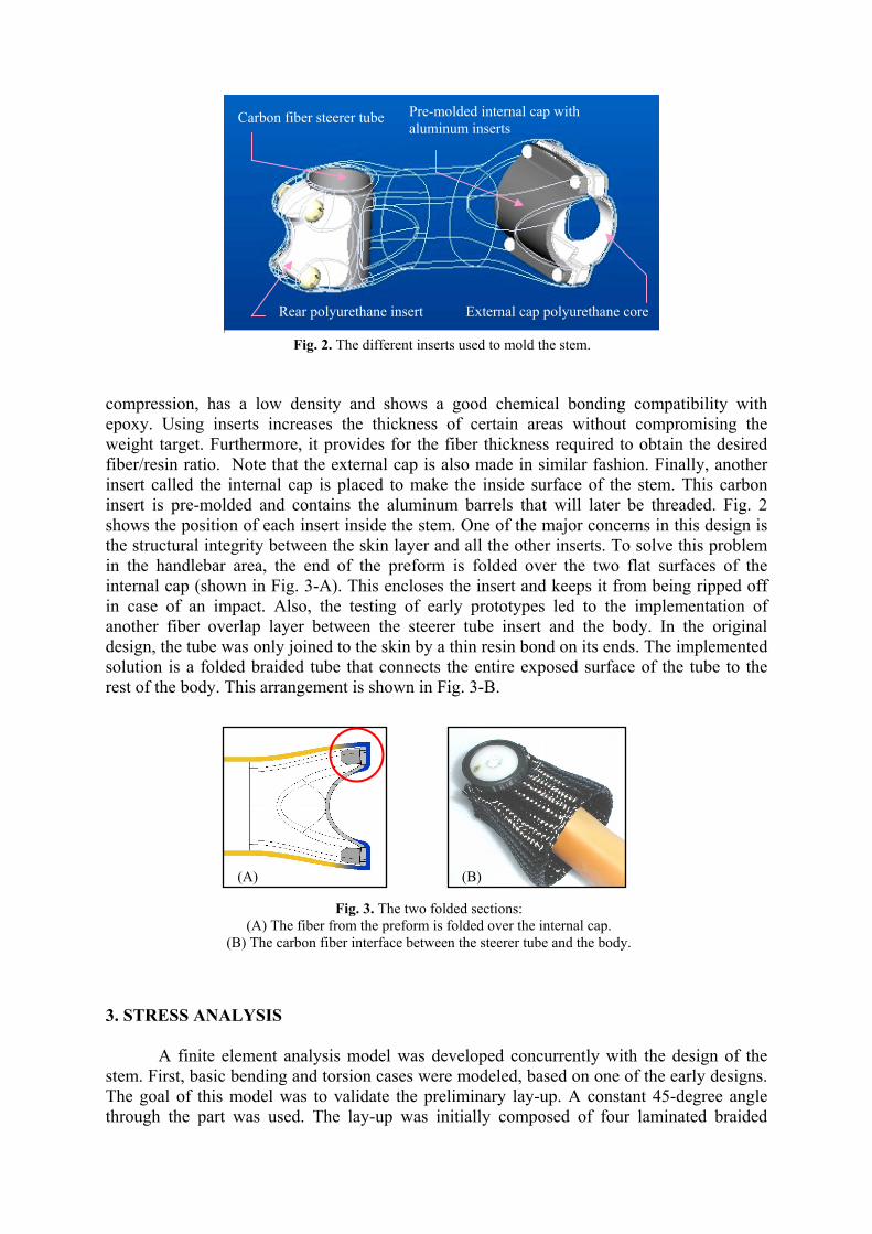
Rear polyurethane insert
Carbon fiber steerer tube
External cap polyurethane core
Fig. 2. The different inserts used to mold the stem.
Pre-molded internal cap with aluminum inserts
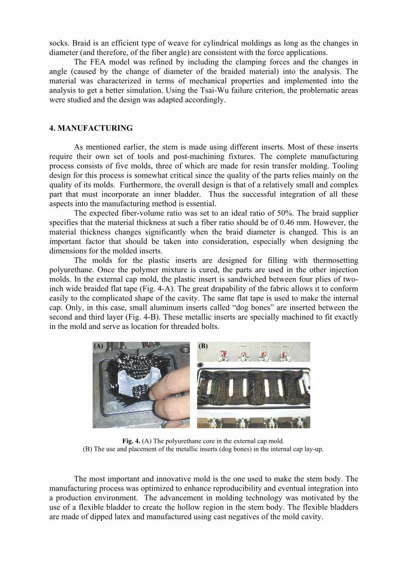
compression, has a low density and shows a good chemical bonding compatibility with epoxy. Using inserts increases the thickness of certain areas without compromising the weight target. Furthermore, it provides for the fiber thickness required to obtain the desired fiber/resin ratio. Note that the external cap is also made in similar fashion. Finally, another insert called the internal cap is placed to make the inside surface of the stem. This carbon insert is pre-molded and contains the aluminum barrels that will later be threaded. Fig. 2 shows the position of each insert inside the stem. One of the major concerns in this design is the structural integrity between the skin layer and all the other inserts. To solve this problem in the handlebar area, the end of the preform is folded over the two flat surfaces of the internal cap (shown in Fig. 3-A). This encloses the insert and keeps it from being ripped off in case of an impact. Also, the testing of early prototypes led to the implementation of another fiber overlap layer between the steerer tube insert and the body. In the original design, the tube was only joined to the skin by a thin resin bond on its ends. The implemented solution is a folded braided tube that connects the entire exposed surface of the tube to the rest of the body. This arrangement is shown in Fig. 3-B.
(B) (A)
Fig. 3. The two folded sections: (A) The fiber from the preform is folded over the internal cap.
(B) The carbon fiber interface between the steerer tube and the body.
3. STRESS ANALYSIS
A finite element analysis model was developed concurrently with the design of the stem. First, basic bending and torsion cases were modeled, based on one of the early designs. The goal of this model was to validate the preliminary lay-up. A constant 45-degree angle through the part was used. The lay-up was initially composed of four laminated braided
socks. Braid is an efficient type of weave for cylindrical moldings as long as the changes in diameter (and therefore, of the fiber angle) are consistent with the force applications.
The FEA model was refined by including the clamping forces and the changes in angle (caused by the change of diameter of the braided material) into the analysis. The material was characterized in terms of mechanical properties and implemented into the analysis to get a better simulation. Using the Tsai-Wu failure criterion, the problematic areas were studied and the design was adapted accordingly. 4. MANUFACTURING
As mentioned earlier, the stem is made using different inserts. Most of these inserts
require their own set of tools and post-machining fixtures. The complete manufacturing process consists of five molds, three of which are made for resin transfer molding. Tooling design for this process is somewhat critical since the quality of the parts relies mainly on the quality of its molds. Furthermore, the overall design is that of a relatively small and complex part that must incorporate an inner bladder. Thus the successful integration of all these aspects into the manufacturing method is essential.
The expected fiber-volume ratio was set to an ideal ratio of 50%. The braid supplier specifies that the material thickness at such a fiber ratio should be of 0.46 mm. However, the material thickness changes significantly when the braid diameter is changed. This is an important factor that should be taken into consideration, especially when designing the dimensions for the molded inserts.
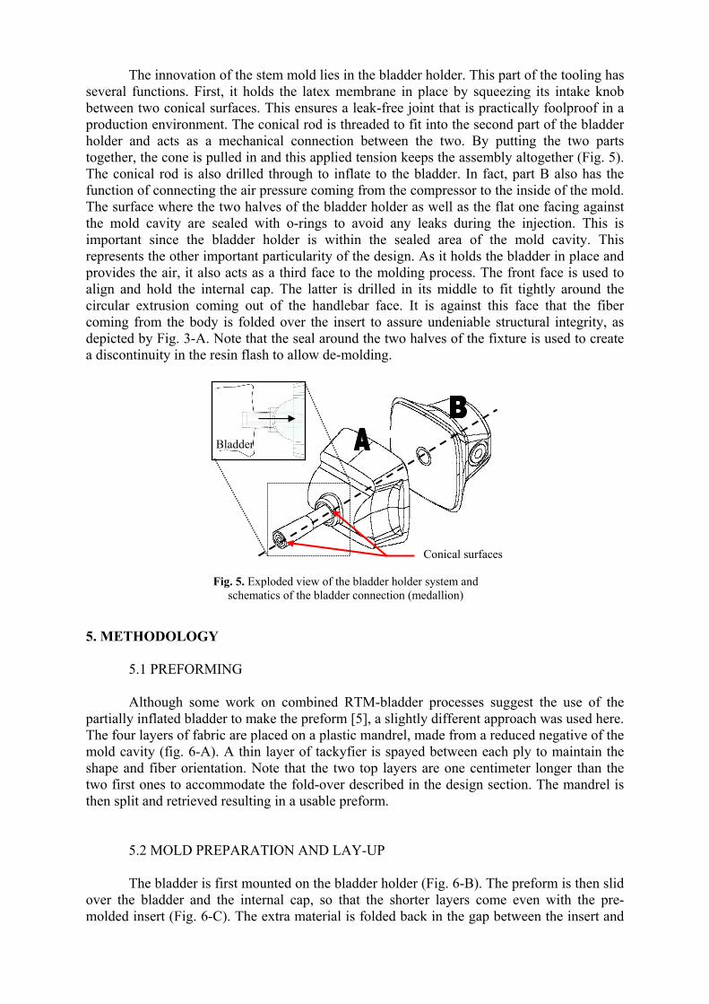
The molds for the plastic inserts are designed for filling with thermosetting polyurethane. Once the polymer mixture is cured, the parts are used in the other injection molds. In the external cap mold, the plastic insert is sandwiched between four plies of two-inch wide braided flat tape (Fig. 4-A). The great drapability of the fabric allows it to conform easily to the complicated shape of the cavity. The same flat tape is used to make the internal cap. Only, in this case, small aluminum inserts called “dog bones” are inserted between the second and third layer (Fig. 4-B). These metallic inserts are specially machined to fit exactly in the mold and serve as location for threaded bolts.
(B)(A)
Fig. 4. (A) The polyurethane core in the external cap mold. (B) The use and placement of the metallic inserts (dog bones) in the internal cap lay-up.
The most important and innovative mold is the one used to make the stem body. The manufacturing process was optimized to enhance reproducibility and eventual integration into a production environment. The advancement in molding technology was motivated by the use of a flexible bladder to create the hollow region in the stem body. The flexible bladders are made of dipped latex and manufactured using cast negatives of the mold cavity.
The innovation of the stem mold lies in the bladder holder. This part of the tooling has several functions. First, it holds the latex membrane in place by squeezing its intake knob between two conical surfaces. This ensures a leak-free joint that is practically foolproof in a production environment. The conical rod is threaded to fit into the second part of the bladder holder and acts as a mechanical connection between the two. By putting the two parts together, the cone is pulled in and this applied tension keeps the assembly altogether (Fig. 5). The conical rod is also drilled through to inflate to the bladder. In fact, part B also has the function of connecting the air pressure coming from the compressor to the inside of the mold. The surface where the two halves of the bladder holder as well as the flat one facing against the mold cavity are sealed with o-rings to avoid any leaks during the injection. This is important since the bladder holder is within the sealed area of the mold cavity. This represents the other important particularity of the design. As it holds the bladder in place and provides the air, it also acts as a third face to the molding process. The front face is used to align and hold the internal cap. The latter is drilled in its middle to fit tightly around the circular extrusion coming out of the handlebar face. It is against this face that the fiber coming from the body is folded over the insert to assure undeniable structural integrity, as depicted by Fig. 3-A. Note that the seal around the two halves of the fixture is used to create a discontinuity in the resin flash to allow de-molding.
Conical surfaces
Bladder
Fig. 5. Exploded view of the bladder holder system and schematics of the bladder connection (medallion)
5. METHODOLOGY
5.1 PREFORMING Although some work on combined RTM-bladder processes suggest the use of the
partially inflated bladder to make the preform [5], a slightly different approach was used here. The four layers of fabric are placed on a plastic mandrel, made from a reduced negative of the mold cavity (fig. 6-A). A thin layer of tackyfier is spayed between each ply to maintain the shape and fiber orientation. Note that the two top layers are one centimeter longer than the two first ones to accommodate the fold-over described in the design section. The mandrel is then split and retrieved resulting in a usable preform.
5.2 MOLD PREPARATION AND LAY-UP The bladder is first mounted on the bladder holder (Fig. 6-B). The preform is then slid
over the bladder and the internal cap, so that the shorter layers come even with the pre-molded insert (Fig. 6-C). The extra material is folded back in the gap between the insert and
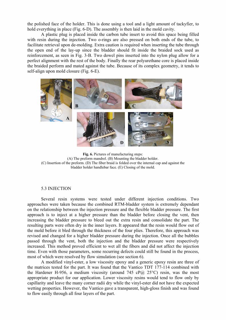
the polished face of the holder. This is done using a tool and a light amount of tackyfier, to hold everything in place (Fig. 6-D). The assembly is then laid in the mold cavity.
A plastic plug is placed inside the carbon tube insert to avoid this space being filled with resin during the injection. Two o-rings are also pressed on both ends of the tube, to facilitate retrieval upon de-molding. Extra caution is required when inserting the tube through the open end of the lay-up since the bladder should fit inside the braided sock used as reinforcement, as seen in Fig. 3-B. Two dowel pins inserted into the nylon plug allow for a perfect alignment with the rest of the body. Finally the rear polyurethane core is placed inside the braided perform and mated against the tube. Because of its complex geometry, it tends to self-align upon mold closure (Fig. 6-E).
E D
B C
A
Fig. 6. Pictures of manufacturing steps: (A) The preform mandrel. (B) Mounting the bladder holder.
(C) Insertion of the preform. (D) The fiber braid is folded over the internal cap and against the bladder holder handlebar face. (E) Closing of the mold.
5.3 INJECTION Several resin systems were tested under different injection conditions. Two
approaches were taken because the combined RTM-bladder system is extremely dependant on the relationship between the injection pressure and the flexible bladder pressure. The first approach is to inject at a higher pressure than the bladder before closing the vent, then increasing the bladder pressure to bleed out the extra resin and consolidate the part. The resulting parts were often dry in the inner layers. It appeared that the resin would flow out of the mold before it bled through the thickness of the four plies. Therefore, this approach was revised and changed for a higher bladder pressure during the injection. Once all the bubbles passed through the vent, both the injection and the bladder pressure were respectively increased. This method proved efficient to wet all the fibers and did not affect the injection time. Even with those parameters, some recurring defects could still be found in the process, most of which were resolved by flow simulation (see section 6). A modified vinyl-ester, a low viscosity epoxy and a generic epoxy resin are three of the matrices tested for the part. It was found that the Vantico TDT 177-114 combined with the Hardener H-956, a medium viscosity (around 745 cP@ 25°C) resin, was the most appropriate product for our application. Lower viscosity resins would tend to flow only by capillarity and leave the many corner radii dry while the vinyl-ester did not have the expected wetting properties. However, the Vantico gave a transparent, high-gloss finish and was found to flow easily through all four layers of the part.
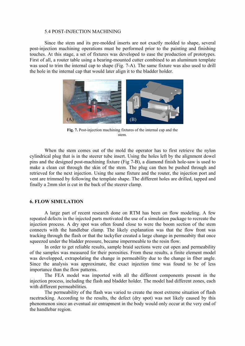
5.4 POST-INJECTION MACHINING Since the stem and its pre-molded inserts are not exactly molded to shape, several
post-injection machining operations must be performed prior to the painting and finishing touches. At this stage, a set of fixtures was developed to ease the production of prototypes. First of all, a router table using a bearing-mounted cutter combined to an aluminum template was used to trim the internal cap to shape (Fig. 7-A). The same fixture was also used to drill the hole in the internal cap that would later align it to the bladder holder.
(B)(A)
Fig. 7. Post-injection machining fixtures of the internal cap and the stem.
When the stem comes out of the mold the operator has to first retrieve the nylon cylindrical plug that is in the steerer tube insert. Using the holes left by the alignment dowel pins and the designed post-machining fixture (Fig 7-B), a diamond finish hole-saw is used to make a clean cut through the skin of the stem. The plug can then be pushed through and retrieved for the next injection. Using the same fixture and the router, the injection port and vent are trimmed by following the template shape. The different holes are drilled, tapped and finally a 2mm slot is cut in the back of the steerer clamp. 6. FLOW SIMULATION
A large part of recent research done on RTM has been on flow modeling. A few repeated defects in the injected parts motivated the use of a simulation package to recreate the injection process. A dry spot was often found close to were the boom section of the stem connects with the handlebar clamp. The likely explanation was that the flow front was tracking through the flash or that the tackyfier created a large change in permeabity that once squeezed under the bladder pressure, became impermeable to the resin flow.
In order to get reliable results, sample braid sections were cut open and permeability of the samples was measured for their porosities. From these results, a finite element model was developped, extrapolating the change in permeability due to the change in fiber angle. Since the analysis was approximate, the exact injection time was found to be of less importance than the flow patterns.
The FEA model was imported with all the different components present in the injection process, including the flash and bladder holder. The model had different zones, each with different permeabilities.
The permeability of the flash was varied to create the most extreme situation of flash racetracking. According to the results, the defect (dry spot) was not likely caused by this phenomenon since an eventual air entrapment in the body would only occur at the very end of the handlebar region.
A closer look at the process showed that when the preform was made, the thumb pressure from the operator was always applied at the same place, creating a thighter area in the braid. Later injections, made with this in mind and much less tackyfier, did not show the discussed defect. As mentioned in Shin and Lee [10], taking into account the compatiblity and quantity of tackyfier used in RTM is critical for repeatabily of mechanical properties. This example also showed how FEA injection models are difficult to refine, since the process can greatly change permeability from one part to the other. 7. TESTING
In order to verify the viability of the design, four tests were performed, in accordance
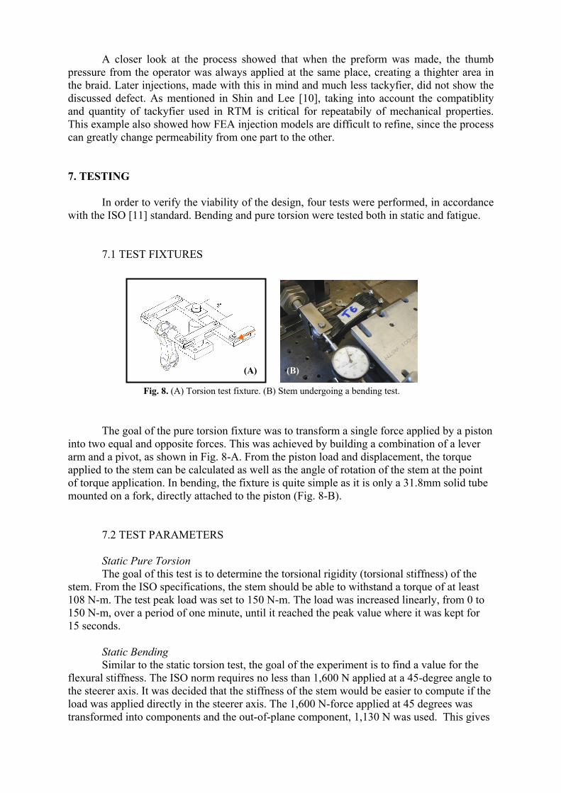
with the ISO [11] standard. Bending and pure torsion were tested both in static and fatigue. 7.1 TEST FIXTURES
(A)
Fig. 8. (A) Torsion test fixture. (B) Stem undergoing a bending test.
(B)
The goal of the pure torsion fixture was to transform a single force applied by a piston into two equal and opposite forces. This was achieved by building a combination of a lever arm and a pivot, as shown in Fig. 8-A. From the piston load and displacement, the torque applied to the stem can be calculated as well as the angle of rotation of the stem at the point of torque application. In bending, the fixture is quite simple as it is only a 31.8mm solid tube mounted on a fork, directly attached to the piston (Fig. 8-B).
7.2 TEST PARAMETERS
Static Pure Torsion
The goal of this test is to determine the torsional rigidity (torsional stiffness) of the stem. From the ISO specifications, the stem should be able to withstand a torque of at least 108 N-m. The test peak load was set to 150 N-m. The load was increased linearly, from 0 to 150 N-m, over a period of one minute, until it reached the peak value where it was kept for 15 seconds.
Static Bending
Similar to the static torsion test, the goal of the experiment is to find a value for the flexural stiffness. The ISO norm requires no less than 1,600 N applied at a 45-degree angle to the steerer axis. It was decided that the stiffness of the stem would be easier to compute if the load was applied directly in the steerer axis. The 1,600 N-force applied at 45 degrees was transformed into components and the out-of-plane component, 1,130 N was used. This gives
essentially the same bending load as the ISO test. Once again, the load was increased linearly from 0 to 1,130N over a period of one minute and then maintained at its peak for 15 seconds before being released.
Torsion Fatigue The load was applied in a sinusoidal manner with a torque amplitude of 94 N-m. The fatigue cycle went from the positive torsion to the negative torsion regimes (fully reversed fatigue loading). The part was alternatively twisted in both directions for 10,000 to 20,000 cycles, at a rate of one cycle every 4 seconds.
Bending Fatigue The bending fatigue test was performed in both inward and outward directions, as prescribed by ISO. We applied a 950 N load amplitude with fully reversed loading (cycling from 950 N to –950 N) for 10,000 cycles, using a rate of one cycle every 4 seconds.
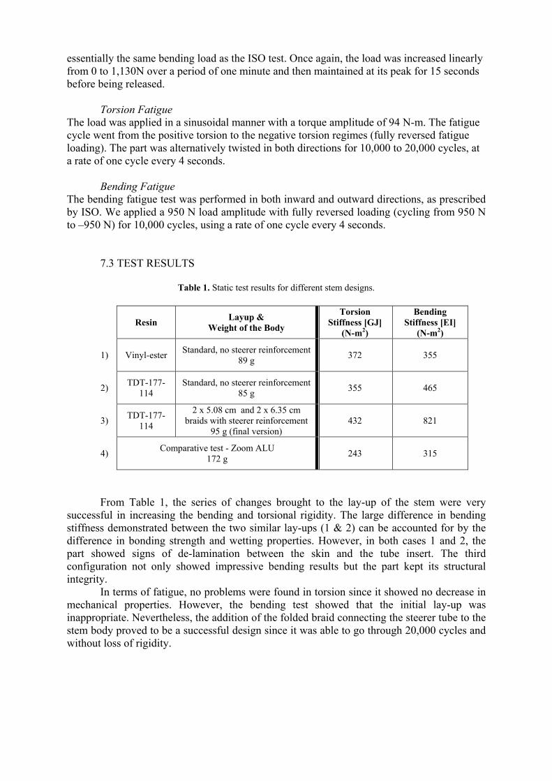
7.3 TEST RESULTS
Table 1. Static test results for different stem designs.
Resin Layup & Weight of the Body
Torsion Stiffness [GJ]
(N-m2)
Bending Stiffness [EI]
(N-m2)
1) Vinyl-ester Standard, no steerer reinforcement89 g 372 355
2) TDT-177-114
Standard, no steerer reinforcement 85 g 355 465
3) TDT-177-114
2 x 5.08 cm and 2 x 6.35 cm braids with steerer reinforcement
95 g (final version) 432 821
4) Comparative test - Zoom ALU 172 g 243 315
From Table 1, the series of changes brought to the lay-up of the stem were very
successful in increasing the bending and torsional rigidity. The large difference in bending stiffness demonstrated between the two similar lay-ups (1 & 2) can be accounted for by the difference in bonding strength and wetting properties. However, in both cases 1 and 2, the part showed signs of de-lamination between the skin and the tube insert. The third configuration not only showed impressive bending results but the part kept its structural integrity.
In terms of fatigue, no problems were found in torsion since it showed no decrease in mechanical properties. However, the bending test showed that the initial lay-up was inappropriate. Nevertheless, the addition of the folded braid connecting the steerer tube to the stem body proved to be a successful design since it was able to go through 20,000 cycles and without loss of rigidity.
8. CONCLUSIONS This research exposes the different aspects of the successful design and manufacturing of a carbon fiber handlebar stem for a bicycle. The main design goal was met since it maximized the use of carbon fiber over metallic parts. Moreover, the weight target was attained, with the part weighing under 125g. The concurrent design and mechanical analysis helped to design a shape without any stress concentrations.
The combined molding using RTM and an inflatable core presented difficulties but proved to be the most efficient process for this application. The development of a multi-purpose bladder holder allowed the part to come out of the mold without any further bonding required. Also, the design of a set-up of post-injection machining fixtures allowed for repeatability in the production of prototypes.
These prototypes were used to perform tests and find an important flaw in the design that was solved by adding extra reinforcement in the lay-up. The modifications showed impressive behavior in torsion and in bending.
The design of the manufacturing system shows how it is possible to use the inner bladder/RTM molding method, even when the part is relatively small and complex in terms of shape and inserts. Thus, the method shows great potential for use in other industries such as aerospace. ACKNOWLEDGEMENTS The authors wish to acknowledge True Temper Sports for financial support as well as Eric St-Amant and Nicolas Verzeni for engineering support. References
1. Nelson, R., “Bike frame races carbon consumer goods forward”. Reinforced Plastics, 47/7 (2003), 36-40
2. Lessard, L., Nemes, J. and Lizotte, P., "Utilization of FEA in the Design Of Composite Bicycle Frames", Composites, 26/1 (1995), 72-74.
3. Lizotte, P., “Stress Analysis and Fabrication of Composite Monocoque Bicycle Frames”, M.Eng Thesis, McGill University, 1996.
4. Lane, D. M., Kutz, J. J., DeRoos, S. D. and Alesse, K. R., “Comparison of processing techniques for the molding of hollow advanced composite parts”, Proceedings of the 38th International SAMPE Symposium and Exhibition, 38/1 (1993), 522-532
5. Michaeli, W., Dyckhoff, J. and Jehrke, M., “Production of structural hollow fibre reinforced components using a combined RTM and blow-up technology”, Proceedings of the 38th International SAMPE Symposium and Exhibition, 38/2 (1993), 2092-2101
6. Lehmann, U. and Michaeli, W., “Improved processing of resin transfer molding for the production of hollow parts with inflatable bladders”, Proceedings of the 42nd International SAMPE Symposium and Exhibition, 42/1 (1997), 13-23
7. Lehmann, U. and Michaeli, W., “Combined moulding speeds hollow parts”, Reinforced Plastics, 40/3 (1996), 40-43
8. Lehmann, U. and Michaeli, W., “Cores lead to an automated production of hollow composite parts in resin transfer moulding”, Compos Part A-Appl S, 29/7 (1998), 803-810
9. Lehmann, U. and Michaeli, W., “Preforming of fiber reinforced hollow components with the RTM /bladder molding process”, Advanced composites; Proceedings of the 9th Annual ACCE Conference, 9 (1997), 531-541
10. Shih, C.-H., Lee, L. J. and Coyle, L. W., “Tackification of textile fiber preforms in resin transfer molding”, Annual Forum Proceedings - American Helicopter Society, 1 (1999), 783-797
11. “ISO 4210” (1996), rev. 2001-08-15