Embed Size (px)
Citation preview
BioRob 2006- The first IEEE / RAS-EMBS International Conference on Biomedical Robotics and Biomechatronics Pisa, Tuscany, Italy, February 20-22, 2006
Design of a 7 Degree-of-Freedom Upper-Limb Powered Exoskeleton
Joel C. Perry(+), Jacob Rosen (++) (+) Dept. of Mechanical Engineering (++) Dept. of Electrical Engineering
University of Washington, Seattle, WA 98195-2500, USA E-mails: (+) [email protected] (++) [email protected]; URL: http //brl.ee.washington.edu
.Abstract – The exoskeleton is an external structural mechanism with joints and links corresponding to those of the human body. Worn by the human, the exoskeleton transmits torques from proximally located actuators through rigid exoskeletal links to the human joints. This paper presents the development of an anthropometric seven degree-of-freedom powered exoskeleton for the upper limb. The design was based on a database defining the kinematics and the dynamics of the upper limb during daily living activities, as well as workspace analyses, joint ranges of motion, and joint physiological and upper limb anatomical considerations. Proximal placement of motors and distal placement of pulley reductions were incorporated into the design of a cable-driven wearable robotic arm. This design led to low inertias, high-stiffness links, and back-drivable transmissions with zero backlash. Potential applications of the exoskeleton as a wearable robot include use as: (1) a therapeutic and diagnostics device for physiotherapy, (2) an assistive (orthotic) device for human power amplifications, (3) a haptic device in virtual reality simulation, and (4) a master device for teleoperation. *.
Index Terms – Arm, cable-driven, exoskeleton,
design, robot.
I. INTRODUCTION
The exoskeleton is an external structural mechanism with joints and links corresponding to those of the human body. Worn by the human, the exoskeleton transmits torques from proximally located actuators through rigid exoskeletal links to the human joints. The same device with different control algorithms may be used in four fundamental modes of operation: 1) Physiotherapy – The patient wearing an exoskeleton
perform an task based occupation or physical therapy in an active or passive mode with the exoskeleton. [1-7]
2) Assistive Device (human amplifier) – The operator wearing an exoskeleton feels scaled-down loads while interacting with objects and the environment, most of the load being carried by the exoskeleton. [8,9]
. * This work is supported by NSF Grant #0208468 entitled “ Neural Control of an Upper Limb Exoskeleton System” to Jacob Rosen (PI)
3) Haptic device – The subject wearing an exoskeleton can physically interact with virtual reality objects while the forces generated through this interaction are fed back to the user through the exoskeleton conveying the shape stiffness texture or any other physical characteristics of the virtual objects. [10,11]
4) Master Device – Replacing the virtual environment with a real robot the operator may use the exoskeleton to control a robotic system in a teleoperation (master / slave) mode, where the exoskeleton reflects back to the user the forces generated as the slave robot interacts with the environment. [12, 13]
The previous two generations of the current work
consisted of 1-DOF and 3-DOF proof-of-concept prototypes. Although much less complex from a mechanical and controls standpoint, they demonstrated convincingly that a novel method of higher level control using surface electromyographic (sEMG) signals as the primary command was viable [14,15]. The 1-DOF design used bicep and tricep sEMG signals to command the elbow joint torque, whereas the 3-DOF design added two degrees at the shoulder level, incorporating additional sEMG command signals from shoulder muscles.
The human machine interface (HMI) of the operator/exoskeleton is aimed to generate seamless and natural operation of the exoskeleton as if is an extension of the operator body. Given the exoskeleton mechanism and the selected application various control algorithms were proposed (position, force - impedance). To trigger motion in the exoskeleton, these control strategies require the operator to either move part of his/her upper limb, or apply a force on the exoskeleton system. Implementing a neural control, the neural HMI (nHMI) is set at the neuro-muscular level of the human physiological hierarchy, using processed sEMG signals as one of the primary command signals of the system. Incorporating muscle models (myoprocessor) and taking advantage of the electro-mechanical delay inherent to human neuromusculoskeletal physiology, the system can predict the operator’s intention resulting in a more natural integration between the operator and the exoskeleton system [16, 17].
The objective of the current study was to design an anthropometric 7 degree-of-freedom powered exoskeleton system. The design of the system was guided by experimental results of a research study on the kinematics and dynamics of the human arm in daily living activities.

BioRob 2006- The first IEEE / RAS-EMBS International Conference on Biomedical Robotics and Biomechatronics Pisa, Tuscany, Italy, February 20-22, 2006
II. SYSTEM REQUIREMENTS
The design and development of a high performance robotic device is a process with numerous competing factors. The mechanism weight and its stiffness exist at opposite ends of the spectrum. Contributing to these underlying requirements are factors such as the operational workspace, desired joint torques, motor placement, link design, and cable selection. Since the device will operate in direct contact with humans, additional requirements emerge regarding comfort and safety of operation.
A. Kinematic and Dynamic Requirements
To better understand the kinematic and dynamic requirements of an exoskeleton arm for functional use, a pilot study was first performed. Motions of the human arm were recorded during 19 activities of daily living (ADL) using a motion capture system (Vicon, 10-camera) [18]. Frame assignments for the data collection are illustrated in fig. 1.
Results of joint position and joint torque distribution of the entire database about each axis are plotted in fig. 2. While some distributions appear normal in shape, others possess a bi-modal or even tri-modal form where modal canters correspond to key anthropomorphic configurations. These configurations are positions of the arm that occur commonly throughout daily activities, often where joint velocities are low at the initial or final periods of motion trajectories. Mean and median position and torque values are reported in Table I.
Fig. 1 Euler Y-X-Z axes assignment for the Vicon system. Human model from Bodyworks (Zetec, LTD, inc).
B. Safety Requirements
Paramount to HMI’s is the guarantee of safe operation. Safety precautions have been implemented on three levels, built into the mechanical, electrical, and software designs.
In the mechanical design, physical stops prevent segments from excessive excursions that could hyperextend or hyperflex individual joints. Also, pulleys
in some joints are driven purely by friction. This allows the transmission to slip if the force between user and device ever exceeds a set limit.
The electrical system is equipped with three emergency shutoff switches: an enable button that terminates the motor command signal upon release, a large e-stop button for complete power shutoff by the observer, and a similar e-stop foot switch for the user.
Ideally, the above safety measures would go unused as a result of adequate safeguards at the software level. Redundant position sensors (potentiometer - Midori, Fullerton; shaft encoder - HP), one at either end of the power train, monitor both joint motion and motor position. Redundancy of position sensing enables software to monitor power transmission integrity; any slip occurring between the motors and end-effector will result in a position discrepancy and lead to immediate system shut-down. Software limits will also be implemented on commanded motor currents, i.e. motor torques.
Fig. 2 Statistical distribution of human arm joint angles (top) and joint torques (bottom) during 19 activities of daily living. Histograms are plotted sequentially from the top: Vicon axes 1 through 7 – see Fig. 1.

BioRob 2006- The first IEEE / RAS-EMBS International Conference on Biomedical Robotics and Biomechatronics Pisa, Tuscany, Italy, February 20-22, 2006
TABLE I Kinematic and dynamic joint design requirements
1 2 3 4 5 6 7
ROM 110 100 135 150 115 70 150
Mean 42.0 35.4 13.1 92.1 3.1 -4.8 11.7
Median 35.1 41.4 9.1 98.6 3 -9.3 15.9
Mean 7.5 3.8 -4.1 0.90 -0.07 0.10 0.01
Median 8.6 4.3 -3.0 0.35 -0.09 0.08 0.01
RMS 14.3 4.8 12.9 1.9 0.28 0.23 0.10 Tor
que
(Nm
)MEASURE
VICON AXIS A
nlge
(deg
)
C. Physical Human-Machine-Interfaces
A challenging area of the design is the mechanical HMI (mHMI), the physical components that will mechanically couple the human arm and the exoskeleton structure and enable force transmission between them. With awareness that the intended population of users will have varying levels of muscular and functional impairment, an emphasis was placed on designing an interface that can easily be attached to the user.
D. Performance
A widely used quantitative measure to evaluate system performance is bandwidth. Systems having a higher bandwidth are controllable under higher frequency command signals. Limited by the system’s lowest natural frequency, the bandwidth is a measure of how successfully trade-offs between weight and stiffness are made.
A target bandwidth of 10 Hz was selected based on the achievable frequency range of the human arm. Additional target values for the design are outlined in Table II. The actual weight was 3.5 kg and 6.3 kg for link 1 and links 2-7, respectively.
TABLE II
Target values for design performance
Property Target Value Weight (moving links) 6.8 kg (15 lbs) Static Payload (max) 2.5 kg (in hand) Angular Deflection (max) 2 degrees per joint Bandwidth 0-10Hz
III. EXOSKELETAL JOINT DESIGN
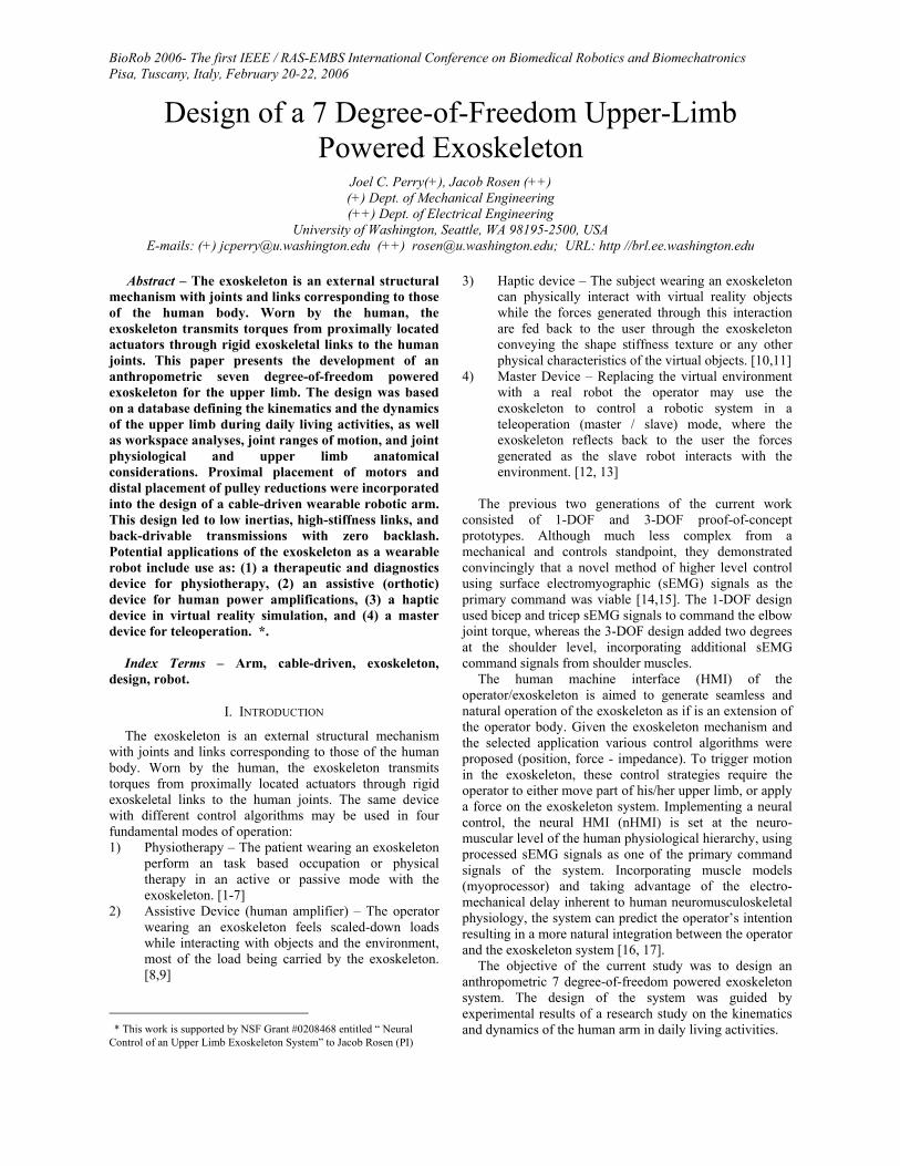
Articulation of the exoskeleton is achieved about seven single-axis revolute joints: one for each shoulder abduction-adduction (abd-add), shoulder flexion-extension (flx-ext), shoulder internal-external (int-ext) rotation, elbow flx-ext, forearm pronation-supination (pron/sup), wrist flx-ext, and wrist radial-ulnar (rad-uln) deviation. The exoskeletal joints are labelled 1 through 7 from proximal to distal in the order shown in fig. 3. Note that the order and orientation of some joints are different from axes presented in fig. 1. Joint orientations are further addressed in section III.D.
A. Anthropomorphic Joints
In the design of the current exoskeleton, three joint configurations emerged. The configurations can be classified as one of the following: a) 90-degree, b) 180-degree, or c) axial.
The distinguishment pertains to the relative alignment of adjoining links when the joint is approximately centered within its range of motion. While some joints of the body articulate about their mid-ROM when adjoining links are near orthogonal (fig. 4a), others do so when the links are near parallel (fig. 4b). A third configuration emerges in axial rotation of both the upper and lower arm segments (fig. 4c). As shown in fig. 4d, exoskeleton joints 1 and 7 are modelled as 180-degree joints, joints 2, 4, and 6 are 90-degree joints, and joints 3 and 5 are axial joints. Joint ROM in configurations (a) and (b) can be increased either by increasing the central radius, r, or decreasing the link width, w (fig. 4a). Adjusting the link offset distance, d, shifts the joint limits, illustrated by red circles, and effectively ‘tunes’ the joint’s mid-ROM.
Consistent with other work, the shoulder complex is reduced to a spherical joint composed of 3 individual axes intersecting at the center of the glenohumeral (GH) joint. The elbow is modelled by a single axis orthogonal to the third shoulder axis. A joint stop prevents the joint from hyperextension. Exoskeletal prono-supination takes place midway between the elbow and wrist joints as it does in the physiological mechanism. And finally, two intersecting orthogonal axes represent the wrist.
B. Human-Machine-Interfaces
Joint configuration (c) presents special challenges in design as a result of the human arm occupying the joint axis of rotation, represented by the elliptical shape in fig. 4c (top). Occurring in axial rotations of both the upper and lower arm, the exoskeleton mHMI uses a semi-circular bearing design to allow users to don the device without strain or discomfort (fig. 3). The semi-circular guides are composed of three 60-degree curved-rail-bearing segments (THK, Tokyo Japan)
Fig. 3 CAD model (Solidworks, Concord) of exoskeletal axes assignment in relation to the human arm. Positive rotations about each joint produce the following motions: 1) combined flx/abd, 2) combined flx/add, 3) int rotation, 4) elbow flx, 5) forearm pron, 6) wrist ext, and 7) wrist rad dev.
BioRob 2006- The first IEEE / RAS-EMBS International Conference on Biomedical Robotics and Biomechatronics Pisa, Tuscany, Italy, February 20-22, 2006
(a)
(b)
(c)
(d)
Fig. 4 The exoskeleton is composed of three joint configurations: 90-degree joints (a), 180-degree joints (b), and axial joints (c). Together the joints produce an exoskeleton structure that achieves full glenohumeral, elbow, and wrist functionality (d).
TABLE III The exoskeleton achieves 99% of the ranges of motion required to
perform daily activities
Joint MotionADL ROM
(deg)EXO ROM
(deg)
Flx-Ext 110 180
Abd-Add 100 180
Int-Ext Rot 135 166
Elbo
w
F lx-Ext 150 150
Flx-Ext 115 120
Rad-Uln Dev 70 60
Pron-Sup 150 155 W
rist
Sh
ould
er
C. Joint Cable Routing
Achieving mechanical joint ranges of motion that match those of the human arm is a challenging task, especially in cable-driven devices where the cables must either be routed through or around the joint axes while maintaining constant length.
The cable routing methods utilized are illustrated in fig. 5. In 90-degree and 180-degree configuration, the cable is wrapped around a pulley, called the ‘joint idler pulley’, which is concentric with the axis of revolution (fig. 5a).
(a)
(b)
(c)
(d) (e)
Fig. 5 Joint cable routing and the effects on ROM using: three equi-diameter pulleys (a), an enlarged joint pulley (c), or an enlarged joint pulley and link offset (d). Also 9-pulley arrangement for axial joints (b), and cabling of stacked pulley (e).
Axial joints are represented by a series of 9 pulleys each located at a constant radius from the axis of revolution, together acting as a single larger-diameter joint idler pulley (fig. 5b).
To maintain constant cable length, the cable must remain in contact with the joint pulley at all times. The sequence shown in fig. 5a shows the extent of joint motion using three equi-diameter cables. In the extreme positions, the shorter length of cable is tangent with the joint pulley and is therefore defined as the joint limit. Fig. 5c illustrates the effect of increasing the joint pulley radius, r, on the amount of clockwise rotation before reaching the joint limit.
Fig. 5d depicts a 90-degree exoskeleton joint and illustrates how an increased joint pulley radius r and offset d equal to r allow links to fold to an angle of zero degrees. Each pulley actually represents a stack of two pulleys per DOF passing through the joint. Two DOF, for example, would require a stack of four pulleys (fig. 5e), two representing the agonist muscle group and two for the antagonist.
To enable bilateral routing of cables, as well as for lightweight strength, mechanical links were designed with high-stiffness I-beam cross-sections.
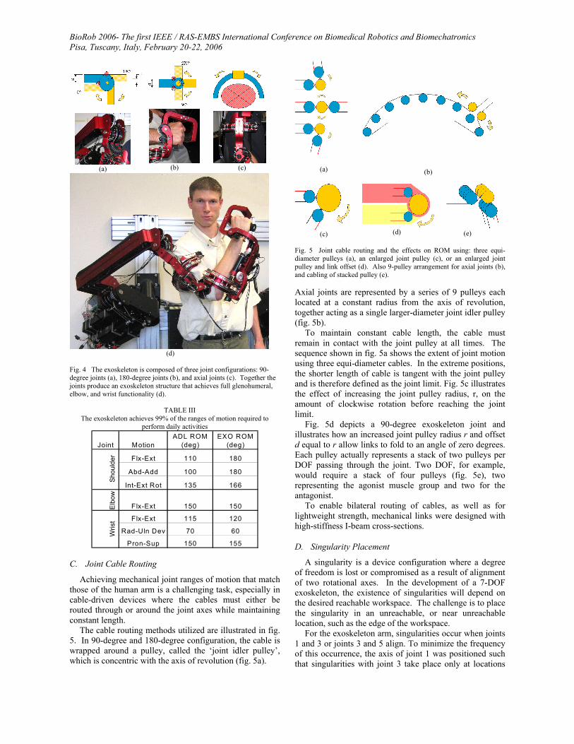
D. Singularity Placement
A singularity is a device configuration where a degree of freedom is lost or compromised as a result of alignment of two rotational axes. In the development of a 7-DOF exoskeleton, the existence of singularities will depend on the desired reachable workspace. The challenge is to place the singularity in an unreachable, or near unreachable location, such as the edge of the workspace.
For the exoskeleton arm, singularities occur when joints 1 and 3 or joints 3 and 5 align. To minimize the frequency of this occurrence, the axis of joint 1 was positioned such that singularities with joint 3 take place only at locations

BioRob 2006- The first IEEE / RAS-EMBS International Conference on Biomedical Robotics and Biomechatronics Pisa, Tuscany, Italy, February 20-22, 2006
that are anthropometrically hard to reach. To allow some user-specific flexibility in the design, the singular position is movable in 15-degree increments. For the placement shown in fig. 6, the singularity can be reached through simultaneous extension and abduction of the upper arm by 47.5 and 53.6 degrees, respectively (fig. 6a). Similarly, the same singularity can be reached through flexion and adduction by 132.5 and 53.6 degrees, respectively (fig. 6b). The singularity between joints 3 and 5 naturally occurs only in full elbow extension, i.e. on the edge of the forearm workspace (fig. 6c). With each of these singularity vectors at or near the edge of the human workspace, the middle of the workspace is free of singularities.
Another aspect to consider when placing singularities is mechanical isotropy. For optimal ease of movement in any direction, singular axes should be placed orthogonal to directions where isotropy is of highest importance. For the singularity placement shown, isotropy will be maximized in 42.5 degrees of shoulder flexion and 26.4 degrees of shoulder abduction, values that lie in the median of shoulder ROM from the ADL study.
(a) (b) (c)
Fig. 6 Mechanical singularities between axes 1 and 3 occur around the shoulder int-ext rotation axis in configurations (a) and (b). A singularity between axes 3 and 5 also occurs in full elbow extension (c).
IV. POWER TRANSMISSION
To date, the transmission of power from one location to another is achieved through a variety of means such as shafts, cables, fluid lines, and gear trains. Each method has specific applications where its characteristics are best suited. In the field of wearable robotics, weight is a critical factor that frequently must be sacrificed for the sake of strength or rigidity. However, development of a rigid structure that lacks adequate bandwidth is as ineffective a tool as one that is lightweight but lacks structural rigidity. To achieve both rigidity and bandwidth, critical decisions were made regarding transmission type and placement of actuators.
A. Cable-Drive Systems
Cable drive systems have been in use on larger scale devices long before their introduction into the world of biorobotics and microsurgery. Their biggest strength lies in their ability to transmit loads over long distances without the friction or backlash inherent to gears. The absence of backlash is achieved through the structural continuity of the cable, enabling a direct link between the driving shaft and the shaft or link being driven. For these reasons, a cable-driven design was selected.
Biomimmetically referred to as tendon-drives, cable-drives are common in robotic applications for their low
backlash, and have been used by Salisbury et al. to achieve back-drivable speed reductions that increase the stiffness of the robotic structure [19]. See section IV.C.
B. Selection and Placement of Actuators
As the heaviest components in the design, placement of the motors was a crucial decision. Motors for joints 1-4 were mounted on the stationary base, achieving a 60% reduction in overall weight of the moving parts. The remaining three motors, whose torque requirements are substantially less, were positioned on the forearm. As each motor carries the weight and inertia of the more distally placed motors, the importance of high power-to-weight ratio increases from shoulder to wrist. Shoulder and elbow joints are each driven by a high torque, low power-to-weight motor (6.23 Nm, 2.2 Nm/kg), while wrist joints are driven by a lower torque, high power-to-weight motor (1.0 Nm, 4.2 Nm/kg). Motors are rare earth, brushed motors (Maxon Motor, Switzerland).
C. Two-Stage Pulley Reduction
Pulleys arrangements can be used to create speed reductions in cable transmissions. Neglecting frictional losses, power throughout the transmission remains constant while tradeoffs between torque and angular velocity can be made. At the motor, required torque is low while angular velocity is high, whereas at the joint, torque is high and angular velocity is low. Lower torque corresponds to lower cable tension in stage 1 (fig. 7), resulting in less strain, and therefore, less stretch per unit length of cable. Minimizing the length of stage 2 and routing the cable in stage 1 through the majority of the robot maximizes the overall transmission stiffness. Two-stage pulley reductions have been implemented in joints 1-4, whereas reductions at the wrist are composed of a single-stage pulley reduction following a single-stage planetary gear reduction.
Fig. 7 Two-Stage pulley reductions produce maximum transmission stiffness when length of high-tension stage 2 is minimized.
V. DISCUSSION
From the study results presented in section II, the largest ROM experience by a joint during the selected daily activities is 150 degrees. Although some studies report joints to achieve ranges of motion exceeding 180 degrees, most joints can only reach such excursions with contributions from neighbouring joints. The G-H joint, for example, appears to provide over 180 degrees of motion about all three axes, however this is due largely to scapular motion. As a result, joints capable of providing 180
BioRob 2006- The first IEEE / RAS-EMBS International Conference on Biomedical Robotics and Biomechatronics Pisa, Tuscany, Italy, February 20-22, 2006
degrees of motion, or less, in the three configurations mentioned above are sufficient to develop an arm exoskeleton with full G-H, elbow, and wrist joint functionality.
Previous exoskeleton designs have primarily utilized internal-external rotation joints and prono-supination joints that fully enclose the arm, requiring the user to insert his/her arm from the end and slide it axially down the length of the arm. This can be a difficult and even uncomfortable task depending on the severity of impairment. In the current exoskeleton, the use of open mHMI’s for both upper and lower arm segments eliminates this difficulty.
Due to the unique placement of the shoulder singularity, as described in section III.D, pure shoulder flexion is achieved through a combination of rotations about joints 1 and 2. Additionally, this unique placement moves the region of highest shoulder joint isotropy into the area of the workspace most often utilized during functional tasks. This confirms that the singularity has been placed in an anthropometrically desirable location.
At the wrist level, although anthropometrically it would be more accurate to incorporate a slight offset between the flexion-extension and radial-ulnar deviation axes, this offset has been neglected for simplicity.
Joint motions that cause significant changes in cable length will result in one of two undesirable effects: either excessively high cable tension, reducing the life of the cables and bearings, or excessively low tension, potentially developing slack, transmission backlash, or even cable derailment. To prevent such occurrences, trans-joint pulley arrangements are kept in contact with the joint pulley at all times, and lateral deviations of the cable at all cable termination sites were limited to 2.5 degrees.
VI. CONCLUSION
In order to promote high performance while ensuring safe operation, the requirements for developing a 7-DOF exoskeleton must be realized and understood both from their technical as well as functional aspects. Additionally, principals of physiological joints and cable-driven systems can assist in achieving a relatively lightweight, high-performance system. Proximal placement of motors, distal placement of pulley reductions, and open mechanica human-machine-interfaces are a few features that add to the performance and ease-of-use of the device. Additional characteristics include low inertias, high-stiffness links, and back-drivable transmissions without backlash. The design achieves full-workspace ROM, as defined by the ADL study.
ACKNOWLEDGMENTS
The authors wish to acknowledge Trevor M. Bardine-Fowler and Levi M. Miller for their vital contributions to the work.
REFERENCES
[1] S.E. Fasoli, et al., "Effects of robotic therapy on motor impairment and recovery in chronic stroke"; Arch. of Phys. Med. & Rehabil, vol. 84, pp. 477-482, 2003.
[2] H.I. Krebs, et al., "Robot-aided neuro-rehabilitation: from evidence-based to science-based rehabilitation," Topics in Stroke Rehabil, vol 8, no. 4, pp. 54-68, 2002.
[3] E. Taub, et al., “Technique to improve chronic motor deficit after stroke,” Arch. of Phys. Med. and Rehabil., 74, 347-54. 1993
[4] N.A. Bayona, J. Bitensky, K. Salter, R. Teasell, “The role of task-specific training in rehabilitation therapies,” Top. Stroke Rehabil, vol. 12, no. 3, pp. 58-65, Summer 2005.
[5] N. Hogan, H.I. Krebs, J. Charnnarong, P. Srikrishna, A. Sharon, “MIT-MANUS: a workstation for manual therapy and training. I,” IEEE Proc. Intl. Workshop on Robot and Human Communication, pp. 161-165, Sept. 1992.
[6] D.J. Reinkensmeyer, N. Hogan, H.I. Krebs, S.L. Lehman, P.S Lum, Chapter 38 - Rehabilitators, robots, and guides: new tools for neurological rehabilitation. In: Winters JM & Crago PE (editors), Biomechanics and Neural Control of Posture and Movement. Springer-Verlag, New York, 2000.
[7] R. Loureiro, F. Amirabdollahian, M. Topping, B. Driessen, W. Harwin, "Upper Limb Mediated Stroke Therapy - GENTLE/s Approach" Special Issue on Rehabilitation Robotics Journal of Autonomous Robots 2003
[8] D.W. Repperger, B.O. Hill, C. Hasser, M. Roark, C.A. Phillips, “Human tracking studies involving an actively powered augmented exoskeleton,” Proc. of the Fifteenth Southern Biomed. Engr. Conf., pp. 28 -31, 1996.
[9] H. Kazerooni, “The human amplifier technology at the university of California, Berkeley,” Robotics and Autonomous Systems, vol. 19, pp. 179-187, 1996.
[10] A. Frisoli, et al., “A new force-feedback arm exoskeleton for haptic interaction in virtual environments,” First Joint Eurohaptics Conf. and Symp. on Haptic Interfaces for Virtual Environment and Teleoperator Systems, pp. 195-2005, March 2005.
[11] M. Bergamasco, et al., “An arm exoskeleton system for teleoperation and virtual environments applications, Proceedings of the IEEE International Conference on Robotics and Automation, vol.2, pp. 1449 -1454, 1994.
[12] B.M. Jau, “Anthropomorphic exoskeleton dual arm/hand telerobot controller,” IEEE International Workshop on Intelligent Robots, pp. 715-718, 1988
[13] D.G. Caldwell, O. Kocak, U. Andersen, “Multi-armed dexterous manipulator operation using glove/exoskeleton control and sensory feedback,” Proc. of the IEEE/RSJ Intl. Conf. on Intelligent Robots and Systems 95. 'Human Robot Interaction and Cooperative Robots', vol. 2, pp. 567 -572, 1995.
[14] J. Rosen, M. B. Fuchs, and M. Arcan, “Performances of hill-type and neural network muscle models—Toward a myosignal based exoskeleton,” Comput. Biomed. Res., vol. 32, no. 5, pp. 415–439, Oct. 1999.
[15] J. Rosen, M. Brand, M.B. Fuchs, M Arcan, “A myosignal-based powered exoskeleton system,” IEEE Trans. On Systems, Man and Cybernetics-Part A: Systems and Humans, vol. 31, no. 3, May 2001
[16] Rosen J., M. B. Fuchs, and M. Arcan, Performances of Hill-Type and Neural Network Muscle Models - Towards a Myosignal Based exoskeleton, Computers and Biomedical Research, Vol. 32, No. 5, pp. 415-439, October 1999.
[17] E. Cavallaro, J. Rosen, J.C. Perry, S. Burns, B. Hannaford, “Hill-based model as a myoprocessor for a neural controlled powered exoskeleton arm – parameters optimization,” Proc. Intl. Conf. on Robotics and Automation, ICRA’05, April 2005
[18] J. Rosen, J.C. Perry, N. Manning, S. Burns, B. Hannaford, “The human arm kinematics and dynamics during daily activities - toward a 7 DOF upper limb powered exoskeleton,” Proc. 12th Intl. Conf. on Advanced Robotics, ICAR '05, pp. 532-539, July 2005
[19] K. Salisbury, W. Townsend, B. Eberman, D. DiPietro, “Preliminary design of a whole-arm manipulation system (WAMS),” Proc. IEEE Int. Conf. On Robotics and Automation, vol. 1, pp. 254-260, April 1988.