Embed Size (px)
Citation preview
Design of a 30-kW RMF-FRC Thruster
Christopher L. Sercel, Joshua M. Woods, Tate M. Gill, Eric Viges, Ricardo G. Van Zanten, and Benjamin A. JornsDepartment of Aerospace Engineering, University of Michigan, Ann Arbor, Michigan
References
RMF Antenna
Contact: [email protected] work was partially supported by the NASA Space Technology Research Fellowship under Grant 80NSSC18K1190
[1] Blevin, H. A., and Thonemann, P. C., “Plasma confinement using an alternating magnetic field,” Nuclear Fusion Supplement, Part 1, 1962, p. 55.[2] Weber, T. E., “The Electrodeless Lorentz Force Thruster Experiment,” Ph.D. thesis, University of Washington, 2010.[3] Woods, J. M., Jorns, B. A., , and Gallimore, A. D., “Circuit Modeling of Rotating Magnetic Field Field-reversed Configuration Thrusters,” AIAA-2018-4911, 2018
Introduction
• Field-Reversed Configuration (FRC) thrusters could fill the role of high-power (>100 kW), propellant-agnostic thruster
• These devices have been built, but direct measurements are lacking
• Physical mechanisms behind plasmoid acceleration are poorly understood
• We seek to build a test unit to measure thrust and 𝑰𝒔𝒑, and
investigate FRC formation
Significant design heritage makes Lab6 hollow cathode easy to use by reducing engineering complexity relative to pulsed pre-ionization. Requires Xenon
FRC Formation
[3]
An antenna generates a rotating magnetic field (RMF) which drives the azimuthal current in the plasma. Copper tube construction allows coolant flow and increased surface area – important because of .46 mm skin depth at 20 kHz
Design Requirements
• Thruster must operate in repetitive mode (not single shot) at 1 kHz to support measurement with a traditional thrust stand
• Thruster must use a Rotating Magnetic Field (RMF) to generate the plasmoid. Necessary field strength approximately 350 G at 20 kHz →~30 J pulse. Therefore thruster will be 30 kW class
• Supporting infrastructure must be compatible with the Large Vacuum Test Facility at the University of Michigan
• Power processing system must operate in atmosphere to reduce vacuum-related challenges with pulsed power
Plasma Source
Structure
x2
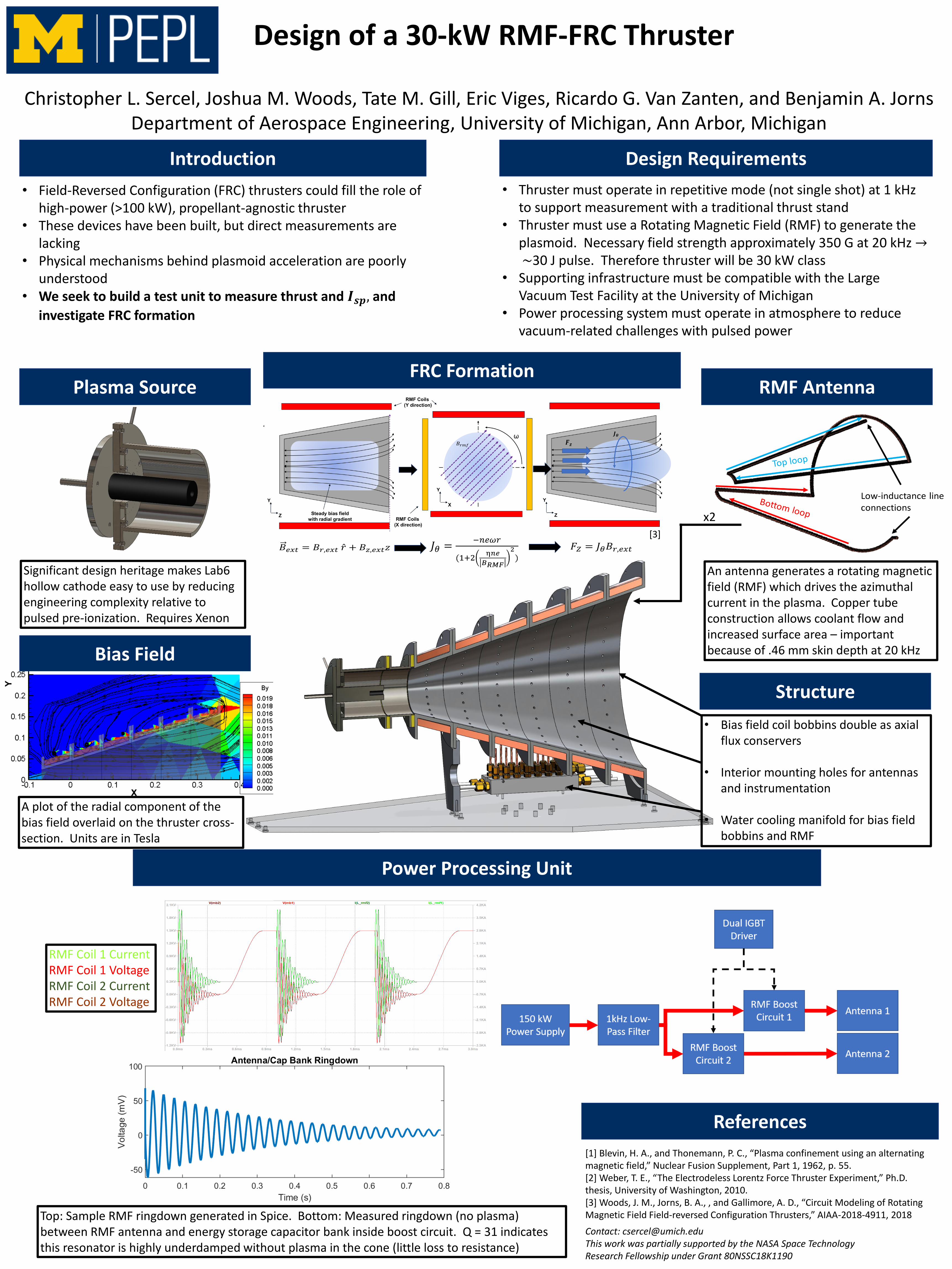
Power Processing Unit
Bias Field
Top: Sample RMF ringdown generated in Spice. Bottom: Measured ringdown (no plasma) between RMF antenna and energy storage capacitor bank inside boost circuit. Q = 31 indicates this resonator is highly underdamped without plasma in the cone (little loss to resistance)
• Bias field coil bobbins double as axial flux conservers
• Interior mounting holes for antennas and instrumentation
• Water cooling manifold for bias field bobbins and RMF
A plot of the radial component of the bias field overlaid on the thruster cross-section. Units are in Tesla
RMF Coil 1 CurrentRMF Coil 1 VoltageRMF Coil 2 CurrentRMF Coil 2 Voltage