Embed Size (px)
DESCRIPTION
442 978-1-4244-4390-1/09/$25.00 ©2009 IEEE 2009 IEEE International Ultrasonics Symposium Proceedings Arne Rønnekleiv 10.1109/ULTSYM.2009.0110 Abstract — The fact that CMUT transducers have not yet made it Authorized licensed use limited to: Univ of Calif San Diego. Downloaded on August 17,2010 at 22:22:55 UTC from IEEE Xplore. Restrictions apply.
Citation preview

Design Modeling of CMUT’s for Medical Imaging
Arne Rønnekleiv Department of electronics and Telecommunications
Norwegian University of Science and Technology, NTNU 7491 Trondheim, Norway
Email: [email protected]
Abstract— The fact that CMUT transducers have not yet made it into commercial products indicates that so far the transducers does not meet the needs of the imaging community. This may be due to low sensitivity for the available arrays, a quality that is improving. But it may also be linked to other problems. One is to maintain high and uniform electromagnetic coupling in the arrays. This is shortly discussed. Another possible reason is linked to neighbor coupling between CMUT’s through the fluid, which leads to resonances. Their dependence on the viscosity in the fluid outside the array is discussed, and how they may be damped by use of lossy uniform layers on top of the CMUT’s. It is also shown how the effects of these resonances may be reduced by use of low impedance amplifiers. Receive amplifiers may be made that does not degrade the signal to noise ratio of the array in reception, even with a large impedance mismatch between CMUT element and amplifier. For many applications medical imaging will soon require full two dimensional (2D) focusing. This requires a high number of independent transducer elements, on the order of several thousands. In turn one then must have at least some focusing electronics close to the CMUT elements. A solution to this problem which assumes that the electronics is integrated between the CMUT arrays and the ultimate backing of the structure is discussed. The discussion assumes that the structure may be considered to be uniform in the transverse direction. Simulations indicate that with improving technologies for bonding of silicon wafers this may be a viable technology.
Keywords-micromachined ultrasound transducers; medical imaging; CMUT modeling
I. INTRODUCTION Work with CMUT’s as a means for both receiving and
transmitting ultrasound was started in the mid 1990-ties [1][2]. To make the CMUT’s one used fabrication methods from the electronic industry on silicon, and this was envisioned to give easy connection between transducers and electronics [2]. They were also early found to give s possibility to adjust the acoustic output impedance over a wide range, to cover media as diverse as gasses and fluids. This inspired work from many authors aiming at a variety of applications [3][4][5][6].
Making CMUT’s for medical imaging required fabrication methods that gave closed cavities to be able to work in immersion [5]. An early comparison of CMUT’s and PZT-transducers for linear arrays is found in [7]. It showed superb
depth resolution for the used centre frequencies for the CMUT due to its large relative bandwidth. But a weakness was also revealed, a reduced penetration depth for the imaging compared to conventional PZT technology. Since the peak output power of the systems are regulated from medical risk considerations, this stems from reduced sensitivity in reception. This deficiency has later been reduced, [8], but seems not to have completely vanished. Together with possible economic factors linked to fabrication, which is fairly unknown to the author, this may be a main reason why CMUT’s have not yet been commercialized in medical imaging.
In the view of the author medical imaging is in a transition from one dimensional to two dimensional electronic focusing. This means from using mainly linear array transducers or at most 1.5 dimensional (1.5D) arrays to 2D arrays. Linear array transducers may focus or change the beam direction in transmission or reception electronically in only one tilt direction. In the orthogonal direction it uses fixed focus, most often by a lens. In 1.5D arrays this focusing may be changed electronically. Both technologies will normally have a number of output cables from the probe counted in hundreds or less, and with no or limited use of electronics in the probe. Full flexibility in imaging with 2D arrays requires an ability to transmit and receive with arrays using thousands of elements. This means that signal processing must be used in the probe, to combine signal from many elements into one out put line, to bring the number of lines from the probe down. For some applications as intravascular imaging, the requirement to the number of cables may be very strict. To have a bright future in medical imaging the CMUT technology should be able to give full flexibility in 2D arrays.
The drive towards 2D arrays may no doubt differ from application to application, but the talk here will discuss obstacles that must be overcome to realize 2D arrays. Many of the solutions to the 2D problem may also be used for simpler systems.
One large field of research deals with the manufacturing of the CMUT’s and the materials used in the CMUT structures. This is an important field but is not dealt with here.
Fig. 1 shows the cross section of a simple circular design which has been assumed in many of the calculations that are presented here. The main body of the paper is organized in three sections that deal with the Mason equivalent circuit, the
442978-1-4244-4390-1/09/$25.00 ©2009 IEEE 2009 IEEE International Ultrasonics Symposium Proceedings
10.1109/ULTSYM.2009.0110
Authorized licensed use limited to: Univ of Calif San Diego. Downloaded on August 17,2010 at 22:22:55 UTC from IEEE Xplore. Restrictions apply.

electromechanical coupling constant, resonances at the CMUT fluid interface, and backing of the CMUT’s.
Figure 1. Cross-section of circular CMUT in a non-collapsed state.
II. EQUIVALENT CIRCUIT AND COUPLING COEFFICIENT
A. Mason equivalent and coupling The Mason equivalent is the basis for building equivalent
circuits for CMUT’s. In its basic form it only deals with one dimensional systems, in our case a CMUT membrane deflected in only one mode. It may be pictured as shown in Fig 2.
Figure 2. A simple Mason equivalent circuit used of CMUT’s.
Here v is the applied small signal voltage, Cm is the static capacitance of the deflected membrane, K(v) the electrical voltage to mechanical force transformer ratio, M the effective mass of the mode and S = Mωou
2 is the spring constant of the mode (ωou is the unloaded resonance frequency of the mode), K(w) the membrane stiffness reduction due to applied dc-voltage, and Za(ω) the acoustic impedance the mode couples to. I most cases this will be a radiation impedance including reactance from moving water mass. Details in the definition of the different parameters are given in [11]. Several of the parameters will depend on the applied DC-voltage for the CMUT, especially K(v) and K(w). Za is frequency dependent. It will also depend on the steering angle for a periodic array of CMUT’s radiating into a fluid.
From the circuit one normally defines two Q-values which both have to be kept low if we want to have broad band low loss transmission from the voltage source v to absorbed power in Za. One is the Q of the mechanical impedance of the circuit to the right of the transformer, which normally is called the mechanical Q, Qm:
( )
0 0Re( ( ))
w
ma
S KQZω ω
−= (1)
Here ω0 is the resonance frequency of this branch and should not be confused with ωou. This Q-factor mainly determines the bandwidth of the transmission from the applied force from the
transformer into the load Za. The other Q-factor is the electrical Q, Qel, of the input admittance of the circuit at ω0. 0 0
( ) 2
Re( ( ))( )
m ael v
C ZQK
ω ω= (2)
The obvious significance of Qel is that it has to be low to allow efficient coupling to Za, even at ω0, if tuning with inductors is not used. Inductors could hardly be used in connection with 2D array elements.
It is well known that the product of these two Q-factors is related to the electromechanical coupling coefficient, or simply the coupling coefficient, k2, of the circuit through the equation:
( ) 22
( ) 2 ( )
( )1/(1 )( ) ( )
v
m el v wm
Kk Q QK C S K
= − =− −
(3)
Fig. 3 shows the insertionloss versus relative frequency at different Qm-values for two different values of k2, 0.5 and 0.7.
Figure 3. Transduction gain versus relative frequency for an ideal Mason CMUT circuit with different values of Qm and k2, top k2 = 0.5, bottom k2 = 0.7. The frequency is normalized to the resonance frequency of the mechanical branch, ω0, and the electrical source impedance is resistive and equal to 1/(ω0Cm). Circles on the curves indicate the 3 dB points. Achieved values of relative bandwidth and peak transduction gain are given in insets in the figures.
As is seen, well above 100 % relative bandwidth may be obtained with moderate added insertionloss, even for k2 = 0.5. Hence large bandwidth may be obtained even for moderate coupling coefficients, but at the expense of increased insertionloss.
A simple and much used way of calculating the coupling coefficient of a CMUT is to derive it from the capacitance of
0 0.5 1 1.5 2 2.5−10
−9
−8
−7
−6
−5
−4
−3
−2
−1
0
Relative frequency
Tra
nsdu
cer
gain
(dB
)
Qm Relative bandw. Peak gain0.4 171 −1.00 dB (blue)0.8 152 % −0.39 dB (green)1.2 124 % −0.07 dB (red)
0 0.2 0.4 0.6 0.8 1 1.2 1.4 1.6 1.8 2−10
−9
−8
−7
−6
−5
−4
−3
−2
−1
0
Relative frequency
Tra
nsdu
cer
gain
(dB
)
Qm Relative bandw. Peak gain0.4 156 % −2.33 dB (blue)0.8 133 % −1.21 dB (green)1.2 111 % −0.58 dB (red)
v Cm
1:K(v)
iωWM
1/(iωW(S-K(w)))
Za(ω)
Membrane Top electrode
Bottom electrode
Center
rmre
t
h1
h2
z-axis
443 2009 IEEE International Ultrasonics Symposium ProceedingsAuthorized licensed use limited to: Univ of Calif San Diego. Downloaded on August 17,2010 at 22:22:55 UTC from IEEE Xplore. Restrictions apply.
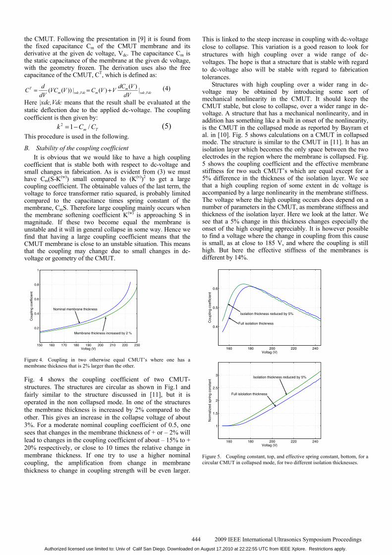
the CMUT. Following the presentation in [9] it is found from the fixed capacitance Cm of the CMUT membrane and its derivative at the given dc voltage, Vdc. The capacitance Cm is the static capacitance of the membrane at the given dc voltage, with the geometry frozen. The derivation uses also the free capacitance of the CMUT, CT, which is defined as:
, ,( )( ( )) | ( ) |T m
m xdc Vdc m xdc VdcdC VdC VC V C V V
dV dV= = + (4)
Here |xdc,Vdc means that the result shall be evaluated at the static deflection due to the applied dc-voltage. The coupling coefficient is then given by: 2 1 /m Tk C C= − (5) This procedure is used in the following.
B. Stability of the coupling coefficient It is obvious that we would like to have a high coupling
coefficient that is stable both with respect to dc-voltage and small changes in fabrication. As is evident from (3) we must have Cm(S-K(w)) small compared to (K(v))2 to get a large coupling coefficient. The obtainable values of the last term, the voltage to force transformer ratio squared, is probably limited compared to the capacitance times spring constant of the membrane, CmS. Therefore large coupling mainly occurs when the membrane softening coefficient K(w) is approaching S in magnitude. If these two become equal the membrane is unstable and it will in general collapse in some way. Hence we find that having a large coupling coefficient means that the CMUT membrane is close to an unstable situation. This means that the coupling may change due to small changes in dc-voltage or geometry of the CMUT.
150 160 170 180 190 200 210 220 230
0.2
0.4
0.6
0.8
1
Cou
plin
g co
effic
ient
Voltag (V)
Nominal membrane thickness
Membrane thickness increased by 2 %
Figure 4. Coupling in two otherwise equal CMUT’s where one has a membrane thickness that is 2% larger than the other.
Fig. 4 shows the coupling coefficient of two CMUT-structures. The structures are circular as shown in Fig.1 and fairly similar to the structure discussed in [11], but it is operated in the non collapsed mode. In one of the structures the membrane thickness is increased by 2% compared to the other. This gives an increase in the collapse voltage of about 3%. For a moderate nominal coupling coefficient of 0.5, one sees that changes in the membrane thickness of + or – 2% will lead to changes in the coupling coefficient of about – 15% to + 20% respectively, or close to 10 times the relative change in membrane thickness. If one try to use a higher nominal coupling, the amplification from change in membrane thickness to change in coupling strength will be even larger.
This is linked to the steep increase in coupling with dc-voltage close to collapse. This variation is a good reason to look for structures with high coupling over a wide range of dc-voltages. The hope is that a structure that is stable with regard to dc-voltage also will be stable with regard to fabrication tolerances.
Structures with high coupling over a wider rang in dc-voltage may be obtained by introducing some sort of mechanical nonlinearity in the CMUT. It should keep the CMUT stable, but close to collapse, over a wider range in dc-voltage. A structure that has a mechanical nonlinearity, and in addition has something like a built in onset of the nonlinearity, is the CMUT in the collapsed mode as reported by Bayram et al. in [10]. Fig. 5 shows calculations on a CMUT in collapsed mode. The structure is similar to the CMUT in [11]. It has an isolation layer which becomes the only space between the two electrodes in the region where the membrane is collapsed. Fig. 5 shows the coupling coefficient and the effective membrane stiffness for two such CMUT’s which are equal except for a 5% difference in the thickness of the isolation layer. We see that a high coupling region of some extent in dc voltage is accompanied by a large nonlinearity in the membrane stiffness. The voltage where the high coupling occurs does depend on a number of parameters in the CMUT, as membrane stiffness and thickness of the isolation layer. Here we look at the latter. We see that a 5% change in this thickness changes especially the onset of the high coupling appreciably. It is however possible to find a voltage where the change in coupling from this cause is small, as at close to 185 V, and where the coupling is still high. But here the effective stiffness of the membranes is different by 14%.
160 180 200 220 240
0.4
0.5
0.6
Cou
plin
g co
effic
ient
Voltag (V)
Full isolation thickness
Isolation thickness reduced by 5%
160 180 200 220 240
1
1.5
2
2.5
3
Nor
mal
ized
spr
ing
cons
tant
Voltag (V)
Full islolation thickness
Isolation thickness reduced by 5%
Figure 5. Coupling constant, top, and effective spring constant, bottom, for a circular CMUT in collapsed mode, for two different isolation thicknesses.
444 2009 IEEE International Ultrasonics Symposium ProceedingsAuthorized licensed use limited to: Univ of Calif San Diego. Downloaded on August 17,2010 at 22:22:55 UTC from IEEE Xplore. Restrictions apply.

It seems that removing coupling variations due to voltage changes introduces unwanted variations in other important CMUT parameters. All CMUT parameter variations should be part of a sensitivity analysis and optimization. Here is still much to be done.
When using a CMUT in reception we only need high coupling in a very narrow voltage range, essentially at the used dc bias point. Whether we would need high coupling over a vide range of voltages in transmission is still an open question to the author. It probably depends on the flexibility of the transmit amplifiers.
III. RESONANCES AT THE CMUT-LIQUID INTERFACE This was one of the earlier anomalies that were detected in
a CMUT array [12][13]. It was early on given the name fluid coupled cross talk between CMUT’s. It is more recently extensively investigated by measurements [14]. It is not cross talk in the more rigid sense of the word. For instance in transmission the array will radiate properly in the desired directions even at frequencies where these resonances occur, provided that the transmit amplifiers are able to deliver the required voltages to the transducer elements. This may be a problem as the array elements will have very low input impedance at these resonances compared to their over all impedances. Similarly in reception, if the load impedance the CMUT’s see is low enough, correct currents are detected from the elements. Only when source or load impedances are high enough distortions occur. In both cases the low impedance of the CMUT resonance will short out the voltage from the source, whether it is the amplifier in transmission or the CMUT elements in reception.
It is generally agreed that the mechanism of the resonances is that neighbor CMUT membranes move with close to opposite phases, and that water is streaming between the CMUT’s. The membranes provide stiffness and some mass to the oscillation, whereas the fluid adds some mass and couples the resonating membranes. It is easy to show that only two membranes that are reasonably close and equal, with a centre to centre spacing well below a wavelength in water, may support such a resonance. In a periodic array the resonances will couple over several CMUT’s, and appear as slow waves along the surface of the array [12][13]. The phase velocity of the cumbersome waves will always be below the wave velocity of the fluid outside the array, as otherwise the oscillation or wave will be rapidly damped by radiation into the fluid. As a consequence we do not se these resonances in an array of single CMUT elements excited to steer in some real direction. An exception is CMUT’s with soft antisymmetric modes which may be resonant at frequencies in the transducer pass band. CMUT’s operating in collapsed mode may be prone to such resonances in the upper part of the passband, see [11], Fig. 5.
If we however excite the CMUT’s using k-vectors of the exciting voltages outside the range which corresponds to propagating waves, we find the resonances. They give regions with very low and very high admittances. It is the high admittances that are harmful. This is shown in Fig. 6 where the magnitude of the admittance of a CMUT array with one CMUT per element, radiating into water, is shown for phase
shifts from 0 to π per CMUT. The structure has a CMUT pitch d of 12.5 μm, and operates in the frequency range 2 to 9 MHz. We see that the high admittance follows a line that starts at a phase velocity along the array surface, 2πf/k, close to 1500 m/s, but is very dispersive.
Assume that we form linear elements in the structure with 6 lines of CMUT’s in each element, and apply voltages to excite a beam at an angle of say 30 degrees (π/6) off broadside. The voltages we excite will correspond to k-vectors in Fig. 6 falling along the black dotted lines. There are 6 lines since we need 6 Fourier components of the applied voltages to obtain constant voltage on the 6 CMUT’s in an element. Five of these lines cross the region with high admittance. We therefore get five such resonances that interfere and give short circuit effects in the array. Each of them is very narrowband with high Q’s and rises to levels 2 orders of magnitude or more above the main admittance level of the CMUT. The total disturbance is fairly broadband due to the dispersion of the waves. It may therefore
Fre
quen
cy (
MH
z)
Phase shift accross CMUT (Rad.)0 0.5 1 1.5 2 2.5 3
2
4
6
8
−6.5
−6
−5.5
−5
−4.5
Figure 6. Contour plot showing log10 of the magnitude of the admittance of one CMUT in an infinite array of CMUT’s as a function of the phase shift across one CMUT, horizontal, and frequency, vertical. Step between contours: 0.2, or 4 dB. Black dotted lines show admittances that are “active” at a steering angle of 30 degrees from broadside. Parameters are as for Array 2 in [15]. Viscosity is as for water.
look like a low Q disturbance. But if the fluid viscosity is low as in water, and other losses in the CMUT’s are small, it is not low Q. When combined with a well matched amplifier, the structure gives an array response as shown in [15], Fig. 3, and also repeated here in Fig. 7.
Beam steering angle [degrees]
Fre
qu
ency
[M
Hz]
0 5 10 15 20 25 30 35 40 452
3
4
5
6
7
8
9x 10
6
−1.5 dB
−2.5 dB
−4.5 dB
−8.5 dB
−7.5 dB
15 dB
−6.5 dB
Figure 7. Response of the array from Fig. 6 when combined with a well matched amplifier.
445 2009 IEEE International Ultrasonics Symposium ProceedingsAuthorized licensed use limited to: Univ of Calif San Diego. Downloaded on August 17,2010 at 22:22:55 UTC from IEEE Xplore. Restrictions apply.
The kx vectors in the voltage along the array that are excited are given by:
, | sin( ) 2 / | /
int( 1) / 2 ( 1) / 2
/ 2 / 2 1 .
x mk m N dc
where m is an eger given bym N to N for N oddm N to N for N even
ω θ π= +
= − − −= − −
(6)
Here c is the wave velocity in the liquid, d is the CMUT period, and N is the number of CMUT lines per element, six in our case. If a total small signal voltage of v is applied to the array, the voltages driving these Fourier components are given by: ,
,,
sin( / 2)( )
sin( / 2)x m
m x mx m
k dNvv kN k d
= (7)
The admittance presented to the exciting voltage is scaled down by the factor (vm/v)2. At an average frequency of 3.5 MHz and the radiation angle θ of 30 deg., the contribution to the input admittance from the six components is calculated. Ordered after decreasing magnitude they become, in % of the full admittance at the given periodicity: 88.7 5.3 2.6 1.4 1.1 0.9. We see that at the array input we only see a small fraction of the real element admittance at these higher k-vectors. Note that the sum of all these coefficients is exactly 100%, meaning that we see the contribution from the total CMUT capacitance, as would be expected.
In [11] it is shown in a similar case that by increasing the viscosity of the fluid by a factor of 1000 we obtain a fairly smooth response of the array. It is also shown that a smooth response may be obtained by adding a resistor in series with each CMUT with a magnitude of 36% of the impedance of a CMUT, before they are combined to form an element. Hence we may reduce the resonances by increasing the losses in the CMUT’s. Adding a resistor may be difficult, and the viscosity is given by the fluid seen by the array, but losses may also be introduced by adding a lossy layer on top of the CMUT array.
This was simulated in [15], and in Fig. 8 we see the response of two slightly different arrays where a lossy top layer is used to damp the resonances, see figure text. One of the arrays is the same as discussed above, the other slightly modified by adding a kerf, a narrow space without CMUT’s, between the elements. Electrical source impedances are as above. The two responses are both fairly smooth. Hence the resonances may be damped out fairly well, if a proper damping material may be found. The added insertion loss is small as shown here, but possibly the bandwidth is slightly reduced.
There has been some uncertainties as to too which degree the viscosity of blood is sufficient to damp out the resonances in transducers used for intravascular imaging. References [17][18] show that the viscosity of blood plasma is about 1.2 mPas and of whole blood about 3 to 4 mPas, compared to .7 mPas for water. Arrays to be used in the blood will work at high frequencies, say 30 MHz, and at these frequencies the thickness of the boundary layer close to the array surface where the shear of the blood takes place, is less than a µm. Hence this layer will mainly be affected by the blood plasma properties.
Beam steering angel [degrees]
Fre
qu
ency
[M
Hz]
0 5 10 15 20 25 30 35 40 452
3
4
5
6
7
8
−1.5 dB −2.5 dB −3.5 dB
Figure 8. Full lines: Transmitted power in dB versus frequency and steering angle for the array of Fig. 7, modified by a soft damping layer. The layer thickness is 17 μm, and it has a shear velocity of 230 m/s, a loss tangent of 0.2, a density of 1200 kg/m3, and a longitudinal velocity of 1900 m/s. The broken lines correspond to a similar structure where a free space of 27.5 μm is added between the array elements.
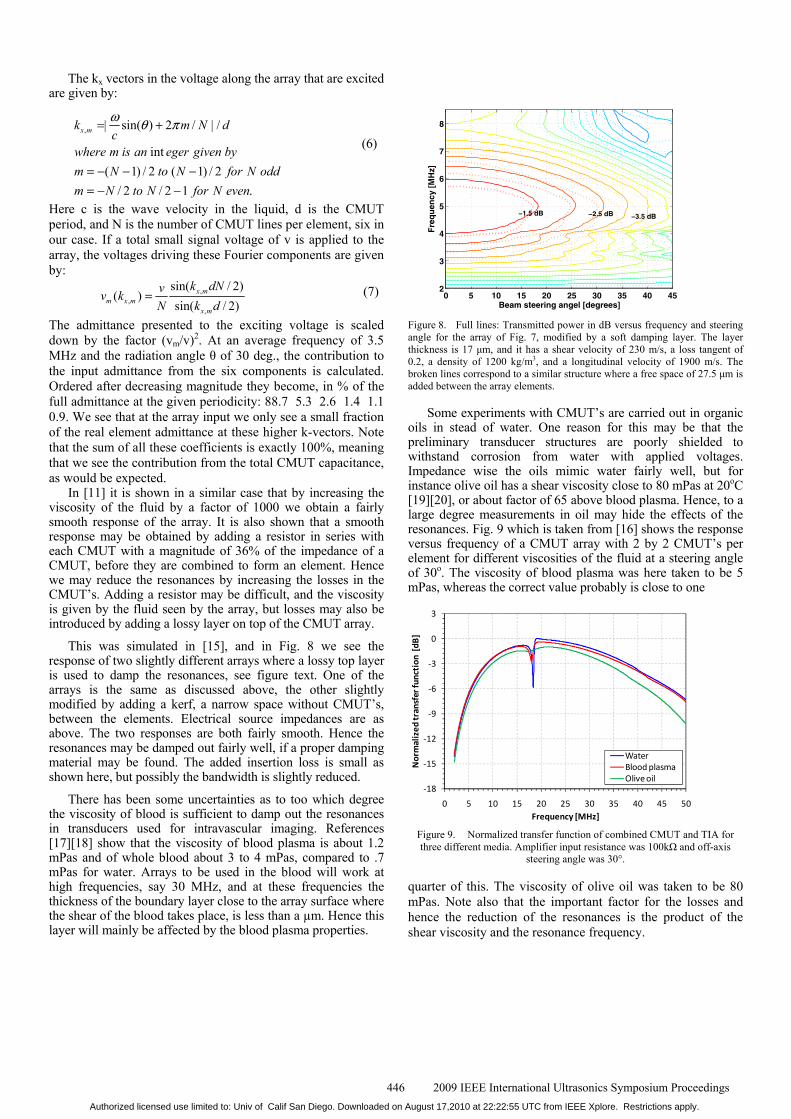
Some experiments with CMUT’s are carried out in organic oils in stead of water. One reason for this may be that the preliminary transducer structures are poorly shielded to withstand corrosion from water with applied voltages. Impedance wise the oils mimic water fairly well, but for instance olive oil has a shear viscosity close to 80 mPas at 20oC [19][20], or about factor of 65 above blood plasma. Hence, to a large degree measurements in oil may hide the effects of the resonances. Fig. 9 which is taken from [16] shows the response versus frequency of a CMUT array with 2 by 2 CMUT’s per element for different viscosities of the fluid at a steering angle of 30o. The viscosity of blood plasma was here taken to be 5 mPas, whereas the correct value probably is close to one
-18
-15
-12
-9
-6
-3
0
3
0 5 10 15 20 25 30 35 40 45 50
Nor
mal
ized
tran
sfer
func
tion
[dB
]
Frequency [MHz]
WaterBlood plasmaOlive oil
Figure 9. Normalized transfer function of combined CMUT and TIA for three different media. Amplifier input resistance was 100kΩ and off-axis
steering angle was 30°.
quarter of this. The viscosity of olive oil was taken to be 80 mPas. Note also that the important factor for the losses and hence the reduction of the resonances is the product of the shear viscosity and the resonance frequency.
446 2009 IEEE International Ultrasonics Symposium ProceedingsAuthorized licensed use limited to: Univ of Calif San Diego. Downloaded on August 17,2010 at 22:22:55 UTC from IEEE Xplore. Restrictions apply.
A different way of handling this problem is to reduce the effect of the resonances rather than damping the resonances. As indicated in the beginning this might be done by playing with the impedances of receiving and transmitting amplifiers. The principal problems with using low impedance transmit amplifiers are probably small and the practical problems will not be discussed here. We will look at the case of reception which is discussed in detail in [16] for a CMUT array with about 30 MHz bandwidth at a centre frequency of 25 MHz to 30 MHz depending on the amplifiers used. One consequence of using low impedance amplifiers is that the acoustic reflectivity of the CMUT array surface will be high. This may be undesired. Here two amplifiers are discussed, a continuous time transimpedance amplifier, TIA, and a charge sampling amplifier, CSA. The circuit of the latter is shown schematically in Fig. 10. As the amplifiers uses short channel field-effect-transistors (90 nm) with high cut off frequencies, they are able to maintain a good signal to noise ratio even if the source impedance level is hundreds of times higher than the effective input impedance of the amplifier. As the figure shows it is basically an operation amplifier with capacitive feedback.
Figure 10. A simplified schematic of the CSA.
During the clock phase ϕ1, the charge from the CMUT flows onto the capacitor Cs and is subsequently sampled and held at the end of ϕ1. The switch S1 is inserted to periodically restore the DC voltage across the transducer. The stored charge is read out by the next stage before ϕ2 goes high and resets the CSA, preparing it for the next clock period. The charge on the capacitor is taken as the output signal. Hence the output signal from the amplifier is a series of charge packets. This may be a good starting point for simple processing steps to reduce the number of output channels from a focused 2D array. The feed back capacitor may be realized in a small space, and the whole amplifier fits easily in the 25 µm by 25 µm footprint of an array element. TIA’s require a feedback resistor which takes much more space for realization than the capacitor of the CSA.
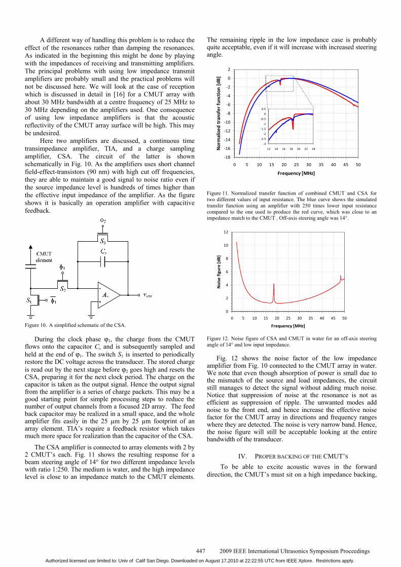
The CSA amplifier is connected to array elements with 2 by 2 CMUT’s each. Fig. 11 shows the resulting response for a beam steering angle of 14° for two different impedance levels with ratio 1:250. The medium is water, and the high impedance level is close to an impedance match to the CMUT elements.
The remaining ripple in the low impedance case is probably quite acceptable, even if it will increase with increased steering angle.
-18
-16
-14
-12
-10
-8
-6
-4
-2
0
2
0 5 10 15 20 25 30 35 40 45 50
Nor
mal
ized
tra
nsfe
r fun
ctio
n [d
B]
Frequency [MHz]
-3
-2.5
-2
-1.5
-1
-0.5
0
0.5
12 14 16 18 20 22 24
Figure 11. Normalized transfer function of combined CMUT and CSA for two different values of input resistance. The blue curve shows the simulated transfer function using an amplifier with 250 times lower input resistance compared to the one used to produce the red curve, which was close to an impedance match to the CMUT . Off-axis steering angle was 14°.
0
2
4
6
8
10
12
0 5 10 15 20 25 30 35 40 45 50
Noi
se fi
gure
[dB]
Frequency [MHz]
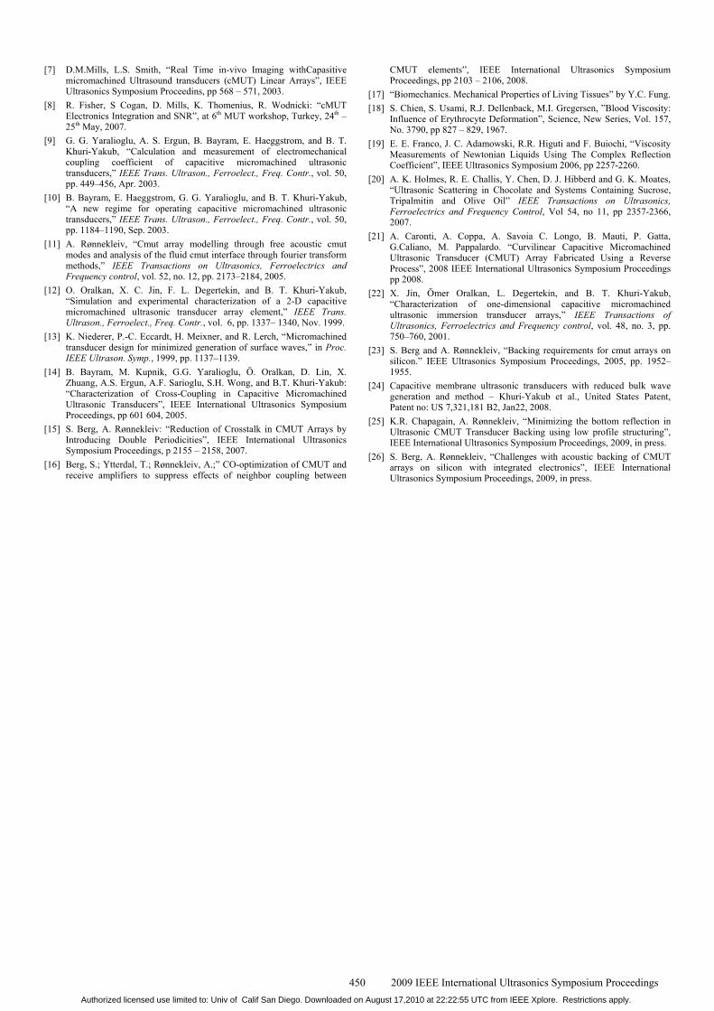
Figure 12. Noise figure of CSA and CMUT in water for an off-axis steering angle of 14° and low input impedance.
Fig. 12 shows the noise factor of the low impedance amplifier from Fig. 10 connected to the CMUT array in water. We note that even though absorption of power is small due to the mismatch of the source and load impedances, the circuit still manages to detect the signal without adding much noise. Notice that suppression of noise at the resonance is not as efficient as suppression of ripple. The unwanted modes add noise to the front end, and hence increase the effective noise factor for the CMUT array in directions and frequency ranges where they are detected. The noise is very narrow band. Hence, the noise figure will still be acceptable looking at the entire bandwidth of the transducer.
IV. PROPER BACKING OF THE CMUT’S To be able to excite acoustic waves in the forward direction, the CMUT’s must sit on a high impedance backing,
447 2009 IEEE International Ultrasonics Symposium ProceedingsAuthorized licensed use limited to: Univ of Calif San Diego. Downloaded on August 17,2010 at 22:22:55 UTC from IEEE Xplore. Restrictions apply.

as they have little mass by themselves. This is most often achieved by forming the CMUT’s on a silicon wafer which is more or less thinned and then backed in a proper way. A special solution is proposed in [21], where essentially all of the silicon is etched away to allow the CMUT’s to be mounted more or less as PZT-transducers. This may be a very interesting solution if one wants to make an array with a curved front surface. But we will not consider it further here. As we are looking for a mounting method to obtain 2D arrays for reception with thousands of elements, we would like to have an amplifier connected to each element. This is especially important for CMUT’s, as they tend to have high electric impedances. Further we would like to have some electronics close to the transducer elements to combine elements into sub apertures. This is a task that is not well solved even for 2D PZT arrays with conventional mounting techniques. We will therefore discuss structures where electronics that is able to address single CMUT elements, is put on wafers below the CMUT’s, see Fig. 13. To our knowledge no such structures have been tested to show adequate ringing performance of the impulse response. It may be possible to break up the electronics wafers such that there is little or no acoustic contact between wafer parts serving different elements. But we will assume here that the electronic wafers are continuous and essentially uniform acoustically. Hence they will form a stiff plate beneath the CMUT’s, together with the silicon wafer that carries the CMUT’s.
It was early on found that such a structure could carry plate modes that would seriously affect the beam steering properties of a CMUT array [22]. The waves in such a plate could be described in several ways. If we look at a plate with a damping layer at the bottom dividing them into surface waves and bulk waves seems reasonable.
In the further discussion of backing of the CMUT we will consider a structure as shown in Fig. 13. Many details in such a structure will be case dependent, as the number of CMUT’s in each element, number of electronic layers and bonding methods. Some of this will be discussed below. Degradation due to surface waves is discussed in detail in [23]. It is confirmed that damping of the wave is required. Even if a good quality damping material with impedance match to the silicon is connected to the back side of the plate, the allowed
Figure 13. Envisioned structure of CMUT array with connected electronics.
thickness of the plate is limited if the array is to function properly. For a [100] oriented wafer, commonly used for electronics, it is found that the wafer should be thinner than 52 % of the wavelength of the vertically polarized shear wave in this cut at the upper band edge of the array. The velocity of this wave is 5843 m/s. We believe the electronics has to determine the orientation. The limit is based on a 1 dB ripple criterion for the array response. The ripple due to the surface wave decreases rapidly with frequency into the pass band of the array.
This gives an upper limit for the wafer thickness for a 10 MHz upper frequency of 300 µm, varying inversely with the frequency. If the silicon consists of several wafers that are glued together with soft materials as epoxy, the allowed thickness may be much reduced.
The backing also has to remove echoes due to signal that penetrate deep into the backing. Here several mechanisms will be active in reducing the disturbing output signal.
If we look at an array in transmission the process of forming an echo from the backing may be as follows. Roughly equal pressure waves will be transmitted into the medium (water) and the silicon. But the particle velocity is much reduced in the silicon due to the higher acoustic impedance. The waves may be attenuated and partly reflected and mode converted when passing through several layers in the backing, both on their way down and up. If the space available for the backing material is large, the propagation losses may be substantial, and it is fairly easy to form bottom surfaces that scatter the waves in directions such that they must propagate a long way to reach the top surface again. Hence the specular reflection that mainly gives cumbersome echoes may be almost zero. If there are substantial reflections between layers in the backing stack, these reflections will reach the top surface and give echoes. If the space behind the array is limited, as for instance in an IVUS probe, the propagation losses could easily be low, and additional damping would be beneficial. In this case the specular reflection could be reduced by either arbitrarily corrugating the back surface or by modifying the surface by a groove like structure, as proposed in [24]. The groove structure proposed in [24] could be further modified as discussed in a parallel talk at this conference [25]. It could give 10 to 20 dB broadband reflections damping of the specularly reflected wave at the bottom surface alone. The structure would have a height of about 0.6 wavelengths of the longitudinal wave in the backing, at the lowest frequency to be damped. The structure scatters the incoming waves into waves with large changes in transverse k-vectors compared to the original waves. In that way it both gives them a long way to go back to the top surface, and makes them less harmful if they should reach the top surface.
The waves that reach back to the top surface through specular reflections has to propagate into the fluid (water) to be harmful. This transmission is reduced by two factors, the impedance mismatch between silicon and water, and the acoustic shorting effect caused by the rather soft CMUT membranes at the interface. When the substrate moves upwards and gives a pressure in the fluid, this pressure will deflect the
448 2009 IEEE International Ultrasonics Symposium ProceedingsAuthorized licensed use limited to: Univ of Calif San Diego. Downloaded on August 17,2010 at 22:22:55 UTC from IEEE Xplore. Restrictions apply.

CMUT membranes, and reduce the acoustic impedance seen by the waves in the substrate well below that of the fluid.
To obtain a feeling of which suppression is required of the reflections from the backing, we have calculated the relative echo power radiated out into water compared to the primary output signal into water, for the following case: The signal
10 20 30 40 50-50
-48
-46
-44
-42
-40
-38
-36
-34
-32
Am
plitu
de (d
B)
Frequency (MHz)
20 dB echo suppression
0 degrees9 degrees18 degrees27 degrees36 degrees45 degrees
Figure 14. Calculated effective echo strength in signal when the backing alone provides a 20 dB echo suppression. The CMUT’s are loaded with a real impedance for maximum signal transfer. The transduction pass band is from 15 MHz to 45 MHz.
reflected back to the backing top surface is reduced by 20 dB compared to what was transmitted into the backing for an array with 30 MHz centre frequency. The result is shown in Fig. 14. We se that in water the suppression is 36 dB or more over the 100 % bandwidth of the array at all steering angles, 0 to 45 degrees off broadside, and with values well above 40 dB for most of this range. This is for an electrical loading of the array that gives close to minimum insertion losses. Reducing the electrical load impedance will increase the suppression. This shows that suppression in the backing by about 20 dB of waves entering the backing is sufficient to give a fair response for the CMUT array. Hence the additional damping needed for specular reflections in addition to the 10 to 20 dB obtainable from the scattering at the bottom surface as discussed above is moderate. But the backing must be able to eventually damp out the scattered waves, possibly both in the bulk of the backing and by propagation out to the sides where there may be more space available. The results in Fig. 14 show that little of the acoustic power is lost to the water.
A second parallel paper at this symposium [26] looks at different ways of bonding CMUT wafers, electronic wafers and damping layers, and how this affects the CMUT array responses. It is found that making a 30 MHz CMUT array with three bonded wafers for integrated circuits seems feasible. Fusion bonding shows the most promising results when it comes to substrate ringing, while SLID and ACA bonding need some improvements when it comes to bonding layer thicknesses. Thicknesses of the wafers in these simulations are in the 10-20 μm range and special care must be taken in the handling of the wafers. At lower frequencies the requirements both to the bonding layer thicknesses and the wafer thicknesses are less stringent, and making such a stack should be easier.
V. CONCLUSION A review is given of some important aspects of designing
CMUT array transducers for medical applications. It is by no means a full review of all that is done to use CMUT’s for medical purposes, but focuses on forming 2D arrays with incorporated electronics, especially in reception. It discuss some aspects of making CMUT’s with high electromechanical coupling coefficient, and it argues that a CMUT with high coupling is a system riding on the edge of an unstable condition. Hence it easily will be prone to manufacturing inaccuracies leading to non-uniformities in arrays. It further discuss neighbor coupling between the CMUT’s through the fluid, which creates resonances. It discusses how the resonances may be reduced by introducing losses, and how their effects may be substantially reduced in reception by using low input impedance amplifiers. This is possible without ruining the signal to noise ratio by using field effect transistors with high cut off frequencies in the amplifiers. Mounting of CMUT arrays is further discussed. The goal is to suppress acoustic ringing in the array while still being able to incorporate a large amount of electronics close to the CMUT elements.
We do not see any obstacles which may not be solved to bring CMUT into medical imaging on a broad scale. But we must realize that it is a hard task to compete with a technology as well developed as the PZT transducer technology.
ACKNOWLEDGEMENT Financial support from the Norwegian Research Council through the projects 159119/130 and 171099/V30 is gratefully acknowledged. The author would also like to thank Prof. Kjell Arne Ingebrigtsen for fruitful discussions and PhD students Sigrid Berg and Kamal Raj Chapagain for their cooperation.
REFERENCES [1] M. I. Haller and B. T. Khuri-Yakub, “A surface micromachined
electrostatic ultrasonic air transducer,” IEEE Trans. Ultrason., Ferroelect., Freq. Contr., vol. 43, pp. 1–6, Jan. 1996.
[2] P.-C. Eccardt, K. Niederer, T. Scheiter, and C. Hierold, “Surface micromachined ultrasound transducers in CMOS technology,” in Proc. IEEE Ultrason. Symp., 1996, pp. 959–962.
[3] I. Ladabaum, X. C. Jin, and B. T. Khuri-Yakub, “Air coupled through transmission of aluminum and other recent results using MUTs,” in Proc. IEEE Ultrason. Symp., 1997, pp. 975–986.
[4] A. Schroder, S. Harasek, M. Kupnik, M. Wiesinger, E. Gornik, E. Benes, and M. Groschl, “A capacitance ultrasonic transducer for high-temperature applications,” IEEE Trans. Ultrason., Ferroelect., Freq. Contr., vol. 51, pp. 896–907, Jul. 2004.
[5] X. C. Jin, O. Oralkan, F. L. Degertekin, and B. T. Khuri-Yakub, “Characterization of one-dimensional capacitive micromachined ultrasonic immersion transducer arrays,” IEEE Trans. Ultrason., Ferroelect., Freq. Contr., vol. 48, pp. 750–760, May 2001.
[6] G. G. Yaralioglu, A. S. Ergun, H. Yongli, and B. T. Khuri-Yakub, “Capacitive micromachined ultrasonic transducers for robotic sensing applications,” in Proc. IEEE Conf. Intell. Robots Syst., 2003, pp. 2347–2352.
449 2009 IEEE International Ultrasonics Symposium ProceedingsAuthorized licensed use limited to: Univ of Calif San Diego. Downloaded on August 17,2010 at 22:22:55 UTC from IEEE Xplore. Restrictions apply.
[7] D.M.Mills, L.S. Smith, “Real Time in-vivo Imaging withCapasitive micromachined Ultrasound transducers (cMUT) Linear Arrays”, IEEE Ultrasonics Symposium Proceedins, pp 568 – 571, 2003.
[8] R. Fisher, S Cogan, D. Mills, K. Thomenius, R. Wodnicki: “cMUT Electronics Integration and SNR”, at 6th MUT workshop, Turkey, 24th – 25th May, 2007.
[9] G. G. Yaralioglu, A. S. Ergun, B. Bayram, E. Haeggstrom, and B. T. Khuri-Yakub, “Calculation and measurement of electromechanical coupling coefficient of capacitive micromachined ultrasonic transducers,” IEEE Trans. Ultrason., Ferroelect., Freq. Contr., vol. 50, pp. 449–456, Apr. 2003.
[10] B. Bayram, E. Haeggstrom, G. G. Yaralioglu, and B. T. Khuri-Yakub, “A new regime for operating capacitive micromachined ultrasonic transducers,” IEEE Trans. Ultrason., Ferroelect., Freq. Contr., vol. 50, pp. 1184–1190, Sep. 2003.
[11] A. Rønnekleiv, “Cmut array modelling through free acoustic cmut modes and analysis of the fluid cmut interface through fourier transform methods,” IEEE Transactions on Ultrasonics, Ferroelectrics and Frequency control, vol. 52, no. 12, pp. 2173–2184, 2005.
[12] O. Oralkan, X. C. Jin, F. L. Degertekin, and B. T. Khuri-Yakub, “Simulation and experimental characterization of a 2-D capacitive micromachined ultrasonic transducer array element,” IEEE Trans. Ultrason., Ferroelect., Freq. Contr., vol. 6, pp. 1337– 1340, Nov. 1999.
[13] K. Niederer, P.-C. Eccardt, H. Meixner, and R. Lerch, “Micromachined transducer design for minimized generation of surface waves,” in Proc. IEEE Ultrason. Symp., 1999, pp. 1137–1139.
[14] B. Bayram, M. Kupnik, G.G. Yaralioglu, Ö. Oralkan, D. Lin, X. Zhuang, A.S. Ergun, A.F. Sarioglu, S.H. Wong, and B.T. Khuri-Yakub: “Characterization of Cross-Coupling in Capacitive Micromachined Ultrasonic Transducers”, IEEE International Ultrasonics Symposium Proceedings, pp 601 604, 2005.
[15] S. Berg, A. Rønnekleiv: “Reduction of Crosstalk in CMUT Arrays by Introducing Double Periodicities”, IEEE International Ultrasonics Symposium Proceedings, p 2155 – 2158, 2007.
[16] Berg, S.; Ytterdal, T.; Rønnekleiv, A.;” CO-optimization of CMUT and receive amplifiers to suppress effects of neighbor coupling between
CMUT elements”, IEEE International Ultrasonics Symposium Proceedings, pp 2103 – 2106, 2008.
[17] “Biomechanics. Mechanical Properties of Living Tissues” by Y.C. Fung. [18] S. Chien, S. Usami, R.J. Dellenback, M.I. Gregersen, ”Blood Viscosity:
Influence of Erythrocyte Deformation”, Science, New Series, Vol. 157, No. 3790, pp 827 – 829, 1967.
[19] E. E. Franco, J. C. Adamowski, R.R. Higuti and F. Buiochi, “Viscosity Measurements of Newtonian Liquids Using The Complex Reflection Coefficient”, IEEE Ultrasonics Symposium 2006, pp 2257-2260.
[20] A. K. Holmes, R. E. Challis, Y. Chen, D. J. Hibberd and G. K. Moates, “Ultrasonic Scattering in Chocolate and Systems Containing Sucrose, Tripalmitin and Olive Oil” IEEE Transactions on Ultrasonics, Ferroelectrics and Frequency Control, Vol 54, no 11, pp 2357-2366, 2007.
[21] A. Caronti, A. Coppa, A. Savoia C. Longo, B. Mauti, P. Gatta, G.Caliano, M. Pappalardo. “Curvilinear Capacitive Micromachined Ultrasonic Transducer (CMUT) Array Fabricated Using a Reverse Process”, 2008 IEEE International Ultrasonics Symposium Proceedings pp 2008.
[22] X. Jin, Ömer Oralkan, L. Degertekin, and B. T. Khuri-Yakub, “Characterization of one-dimensional capacitive micromachined ultrasonic immersion transducer arrays,” IEEE Transactions of Ultrasonics, Ferroelectrics and Frequency control, vol. 48, no. 3, pp. 750–760, 2001.
[23] S. Berg and A. Rønnekleiv, “Backing requirements for cmut arrays on silicon.” IEEE Ultrasonics Symposium Proceedings, 2005, pp. 1952–1955.
[24] Capacitive membrane ultrasonic transducers with reduced bulk wave generation and method – Khuri-Yakub et al., United States Patent, Patent no: US 7,321,181 B2, Jan22, 2008.
[25] K.R. Chapagain, A. Rønnekleiv, “Minimizing the bottom reflection in Ultrasonic CMUT Transducer Backing using low profile structuring”, IEEE International Ultrasonics Symposium Proceedings, 2009, in press.
[26] S. Berg, A. Rønnekleiv, “Challenges with acoustic backing of CMUT arrays on silicon with integrated electronics”, IEEE International Ultrasonics Symposium Proceedings, 2009, in press.
450 2009 IEEE International Ultrasonics Symposium ProceedingsAuthorized licensed use limited to: Univ of Calif San Diego. Downloaded on August 17,2010 at 22:22:55 UTC from IEEE Xplore. Restrictions apply.


![Cancer Imaging Phenomics Toolkit (CaPTk)...[1] Davatzikos et al., Cancer imaging phenomics toolkit: quantitative imaging analytics for precision diagnostics and predictive modeling](https://img.pdfslide.us/doc/110x75/600a0249272aa41135067953/cancer-imaging-phenomics-toolkit-captk-1-davatzikos-et-al-cancer-imaging.jpg)

![Deep-Collapse Operation of Capacitive Micromachined ...sure [17]. These improvements in the output power capa-bility of cmUTs make them good candidates for medical imaging and high-intensity](https://img.pdfslide.us/doc/110x75/5f0d026e7e708231d4383a45/deep-collapse-operation-of-capacitive-micromachined-sure-17-these-improvements.jpg)