Embed Size (px)
Citation preview

REPORT NO. GDCA-DBG73W CONTRACT NAS 8-27738
DESIGN, MANUFACTURE, DEVELOPMENT, TEST, AND EVALUATION OF BORON/ALUMINUM
STRUCTURAL COMPONENTS FOR SPACE SHUTTLE
https://ntrs.nasa.gov/search.jsp?R=19740026203 2020-03-30T03:53:52+00:00Z

REPORT NO. GDCA-DBG73-006 CONTRACT NAS 8-27738
DESIGN, MANUFACTURE, DEVELOPMENT, TEST, AND EVALUATION OF BORON/ALUMINUM
STRUCTURAL COMPONENTS FOR SPACE SHUTTLE
VOLUME IV + REPAIRABILITY
M. F. Miller 1. L. Christian
F. H. Doyal
August 1974
Prepared Under Contract NASb-27738
Submitted to National Aeronautics and Space Administration GEORGE C. MARSHALL SPACE FLIGHT CENTER
Huntsville, Alabama
Prepared by CONVAIR AEROSPACE DIVISION Of GENERAL DYNAMICS
San Diego, California
FOREWORD
The following final report describes work performed on NASA Contract NAS 8-27738 by the Convair Division of General Dynamics Corporation. The work was administered by the Materials Divieion of the Astronautics Laboratory, George C. Marshall Space Flight Center, Huntsville, Ala- bama 35812. Mr. F. P,L-aJaconawaa the NASA project officer.
The program was conducted by the Advanced Composites Group at Convair, San Diego, California. Primary contributors to the program were:
Repairs: C. R. Maikish, A. R, Robertson, L. C. May Component Testing: N. R. Adsit
This report covers the repairability portion of the contract from 1 Octo- ber 1973 to 30 July 1974.
TJd L. Christian Program Manager " ~ e ~ u t ~ Program Manager
PRECEDING PAGE BLANK NOT FILMm
iii

TABLE O F CONTENTS
Section
1 INTRODUCTION
1.1 PROGRAM OBJECTIVES 1.2 ORGANIZATION 1.3 REPAIRABILITY BACKGROUND 1.3.1 Repair of Crippled B/Al Adapter 1.3.2 Repair of Darnaged B/Al-Ti Compression Panel 1.3.3 Repair of Crippled B/Al Hat Section 1.4 NEW TECHNOLOGY
2 REPAIR ABILITY GUIDELINES
FIELD REPAIRS REPAIR MATERLALS CORROSION PRODUCTS TEMPERATURE LIMITATIONS DAMAGE/REPAIR (l/t) RATIO REPAIR OR REPLACEMENT NONDESTRUCTIVE DUPE CTION WEIGHT PENALTY TOLERANCE CUTTING O F DAMAGED MATERLAL
3 COMPONENT REPAIRS
3.1 SANDWICH BEAM TEST 3.2 ELASTIC BUCKLING TUBES 3.3 SHEET STRINGER SPECIMEN 3.4 BORON/ALUMINUM TUBE 3.5 WEB SPLICE 3.6 B/Al TENSION FIELD PANEL
4 CONCLUSIONS AND RECOMMENDATIONS
5 REFERENCES
Page
1-1

LIST OF FIGURES
Figure - Guidelines for B / A ~ Patch Repair 2-3 B/A1 Sandwich Beam Specimen 3-2 Failed Sandwich Beam Specimen 3-2 Repaired Sandwich Beam Specimen 3-3 Retested B/Al Sandwich Beam Specimen 3-4 B/A1 ?\lbes Prior to Damage 3-6 B/Al Tube After Damage 3-6 Crushed B/AI Tubes Repaired by Forming at 788K (950F) 3-7 Foil Reinforced B/Al Tubes Sheet Stringer Specimen Failed Hat Crippling Specimen Repair Plan for Hat Crippling Specimen Repaired Sheet Stringer Specimen Prior to Riveting Testing of Repaired B/A1 Sheet-Stringer Specimen Retested B/Al Sheet Stringer Specimen Failed B/Al Tube Repair Plan for B/Al Tube Specimen Repaired End of B/A1 Tube Failed B / A ~ Tube After Repair and Reteat Web Splice Test Specimen and Fixture Failed Spotwelded Web Splice Test Specimen Photograph of Bolted Repair of Web Splice Specimen Failed Web Splice Specimen Tension Field Test in Progress Failed Tension Field Panel Repair Plan for Tension Field Panel Damaged B/Al Tension Field Specimen Repaired B/Al Tension Field Panel Failure of Repaired B/A1 Tension Field Panel
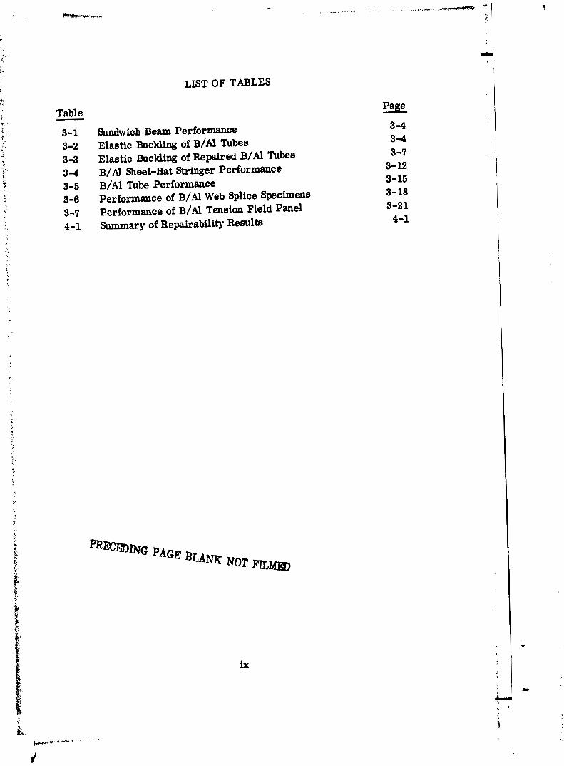
Table - 3-1 3 -2 3-3 3-4 3-5 3-6 3-7 4-1
LIST OF TABLES
Sandwich Beam Performance Elastic Buckling of B/A~ %be8 Elastic Buckling of Repired B/Al Tubes B / A ~ Sheet-Hat Stringer Performaace B / A ~ Tube Performance Performance of B/A1 Web Splice Specimens Performance of B/Al Tension Field Panel Summary of Repairability Results
Page
3 4 3-4 3-7 3- 12 3-15 3- 18 3-2 1 4-1
PRmBING PAGE BLAM NOT m,m

SUMMARY
This portion of the program was performed to determine the repairability of boron/aluminum structural components. Previous program reports defined design and manufacturing criteria necessary for the successful application of these composites and verffied their applicability through structural testing. This report demonstrates that metal matrix com- posfte material, damaged in service, can be repaired by techniques that a re not very different from those currently in use for conventional mate- rials.
A list of repair guidelines was prepared to aid in determining the proper repair techniques for a given structure, These guidelines included spec- ifying types of repair material and their applicability, corrosion preven- tion procedures, design criteria, and inspection criteria.
Six sets of boron/aluminurn structural components were repaired and tested to compare as-fabricated and repaired performance. The speci- mens included a honeycomb-stiffened panel, elastically buckled tubes, a skidstringer panel, a tube combining bending and tension, a splice joint specimen, and a tension field panel. All but one set of specimens, when repaired, exceedd the strength of the origlnal specimens; the repairs resulted in an average weight increase per structure of 9%, and an average performance increase of 27%.
PRECEDING PAGE B L W NOT
SECTION 1
INTRODUCTION
The application of advanced composites, both resin and metal-matrix, to aircraft and missile structure has become prevalent in recent years. It is clear that these high- strength, low-weight composite materials will find additional structural applications on future aerospace vehicles. Previous test articles from this and other government and industry programs (References 1-6) have demonstrated that boron/aluminum tech- nology has progressed sufficiently to be considered for uee on Space Shuttle. In fact, partly because of the present program, boron/aluminum tubular struts have already been baselined for the Space Shuttle Orbiter.
1.1 PROGRAM OBJECTIVES
The objectives of this program were to compare the use of boron,sluminum (B/Al) in Space Shuttle application with other structural materials and to evaluatc material properties, processing techniques, and fabrication characteristics of B/A1 to develop sufficient technology to permit application of B/AI. for Space Shuttle structural com- ponents with a high degree of confidence.
The main portion of the program (References 1, 2) included the design of three thrust structure components for the Space Shuttle, the testing of subcomponent specimens to verify design and joint fabrication concepts, and culminated in the design and fabrica- tion of two components: a 1 by 0.96m (40 by 38 in.) shear beam weighing 35.4 kg (78 lb) designed for service at 366K (200F), and a 2 by 0.7m (80 by 29 in.) compres- sion panel weighing 20.2 kg (44.4 lb) and capable of service up to 589K (600F). These structures successfully demonstrated that B/AI structural components could be fabri- cated and assembled using modified sheet metal technology and today's factory equip- ment. The successful testing of the shear beam component to 110% of design ultimate load is described in Reference 7.
The objective of the repairability phase of the program was both to determine a basic repair approach for metal matrix structures and to demonstrate the applicability of this approach through actual repair testing. A repairability review board, composed of design, material, and processing personnel formulated the repair approached and selected six sets of failed specimens to be repaired and retested. Each selected specimen had its previous testing history recorded, and a photograph was made of the failed specimen. A second photograph wae taken after specimen repair to visually demonstrate the repair technique. A third photograph was then taken after the speci- men was retested so that comparisons could be made regarding the type and location of failure before and after repair.
1.2 ORGANIZ AT1 ON
This report i s divided into four volumes. The first volume (Reference 1) details the design, s tress analysis, and subcomponent testing of structures examined during the progmm. Specifically, designs a re presented for 9.2 by 3. l m (30 by 10 ft) and 1.0 by 0. 96m (40 by 38 in.) shear beams, a 9.2 by 3. l m (30 by 10 ft) truss, and 3.1 by 3. l m (10 by 10 ft) and 2.0 by O.7m (80 by 29 in.) compression panels a s well a s several subcomponent specimens. The second volume (Reference 2) contains material characterization, process devel-rpment, process and material s~ecifications or guide- lines, and manufacturing procloi.ures used in the fabrication of component and sub- component test articles. The third volume (Reference 7) discusses the component testing on the full-scale shear beam test specimen, and compares the B/A1 design of the component with comparable performance structures made from aluminum and titanium, This fourth volume describes the repair techniques for B / A ~ aluminum developed on this program.
1.3 REPAIRABILITY BACKGROUND
Previous to this program, General Dynamics had performed selected repair studies on three structural components made from metal-matrix composites (References 2, 3, an' ). These repair studies, a s well a s the repair of numerous sub-element specimens, formed the basis on which this program was developed.
1.3.1 REPAIR OF CRIPPLED B/A1 ADAPTER. (Reference 3) A PRIME adapter for the Atlas Missile was made in 1968 using B/Al. The composite section of this adapter was 1.5m (5 ft) in diameter and 1.2m (4 ft) high. The hat stringer reinforced croes- plied skin initially failed at 133% of design ultimate load by crippling of three stringers and the skin panels between the hats. Aluminum straps were riveted over the damaged area, and the structure was retested to 100% of design ultimate load without failure.
1.3.2 REPAIR OF DAMAGED B/AI-T~ COMPRESSION PANEL. (Reference 8) A 1.2 by 0.6m (4 by 2 ft) compression panel consisting of eight unidirectional B/AI hats welded to a titanium skin was to be subjected to 589K (600F) compression testing. During heat-up, portions of the pawl attained a temperature in excess of 811K (1000F). This overheating caused buckling of three stringers on one side of the panel.
The huckled stiffenem were successfully straightened ustng the application of heat and pressure to the skin/stiffener. Because i t was n& possible to obtain perfectly straight stringer flanges and because of the possibility that tho boron was degraded due to local overheating, it was decided to reinforce the skin flanges of the three damaged stringers.
Five boron/aluminum angles, [01], 1.09 mm (0.04 In.) thick were hot formed. The angles were attached to the stringers by means of rivets and adhesive bonding, Hexcel 951 materlal was used for the bonding operation. A 0.81 mm (0,032 in.) titanfun
doubler was added to the skin side of the panel. The repaired panel was later success- fully tested at 589K (600F).
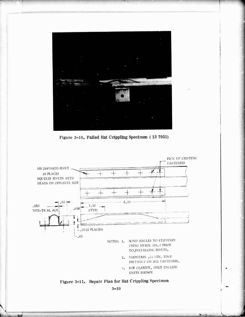
1.3.3 REPAIR OF CRIPPLED B / A ~ HAT SECTION. (Reference 2) A 0.24 cm (0.1 in.) thick B/A~ hat, 48 cm (18 in.) long, was tested in compression at 589K (600F). A post test evaluation disclosed that the testing arrangement did not provide the de- sired end fldty. The specimen had acted a s the center of a 2m (78 in.) column of undetermined fixity. For this reason, a second crippling test was run.
The previously failed B / A ~ stringer was dieassembled and cut to approximately 30.3 cm (12 in.) for retesting, The crippled section was reformed into the desired config- uration at 755K (900F) using wooden tools and graphite lubricant, The hat was resist- ance welded to a 10-ply 0 + 45" skin and retested a t 589K (6OOF). The specimen failed at 133% of design ultimate load.
1.4 NEW TECHNOLOGY
In compliance with the New Technology clause of the contract, personnel assigned to work on the program were advised, and periodically reminded, of their reaponsibillties in the prompt reporting of items of New Technology. In addition, reports genersted a s a result of the contract work were revlewed by the Program Manager a s a further means of identifying items to be reported.
Response was made to all inquiries by the company-appointed New Technology Repre- sentative, and when deemed appropriate, conferences were held with the New Technol- ogy Representative to discuss new developments arising out of current work that could lead to New Technology items. Th: New Technology Representative has the responsi- bility for transmitting reportable items of New Technology to the Technology Utlliza- tion Officer, a s well a s the annual and final reports specified in the Clause.
The Contractor believes the performance of persmnel assodated with the contract has been consistent wtth the requirements of the New Technology clause.

SECTION 2
RE PA1 RABILITY GUIDE LINES
The followlng list of guidelines was used during the repairability studies, These guide- lines were intended for application to structures fabrlcated from 50 v/o B/6061 Al. The applicability of these guidelines was continually assessed during the repairability program.
2.1 FIELD REPAIRS
Primary consideration shall be placed on the application of in situ field repairs; how- - ever it may be necessary to remove specialized items to repair facilities,
2.2 REPAIR MATERIALS
The followlng materials may be considered for uee in B/AI repaire.
a. Aluminum - limited to applications between 211K (-80F) and 422K (300F).
b, Resin Composites - limited to maximum resin composite use temperature.
c. Titanium, Steel, B/Al - no limits.
2,3 CORROSION PRODUCTS
All corrosion products shall be mechanically removed prior to repair. If boron fibers a r e exposed in a joint area, specisl handling may be necessury. The same corrosion prevention system used with the parent structu~+3 shall be applied to the repair, If no corrosion system is in use on the parent structure, and boron fibera a r e exposed o r the repair uses material other than B/A~, a corrosion prevention eyetern compattble with the use temperature shall be applied.
2.4 TEMPERATURE LIMITATIONS
The followlng guidelines shall be used for m i m u m temperature wage during repairs.
a. Heat treated B/Al - maximum applied temperature, 422K (300F).
b. As-Received B/AI - maximum applied temperature, 78SK (950F).
Note: If the repaired structure contains brazed, soldered, o r adhesive joints, temperature limltatione may be imposed by the joint,
c. Cross-Ply Laminate -- if hot formfw i s necessary, the repair should be per- formed ?+ tween 700-783K (800-950F).

The use of a Temple Stick or other temperature monitoring device is recommended when attempting elevated temperature repairs to ensure that maximum temperature limits a re not exceeded; overheating of components during attempted mpair wlll re- sult in cevere stluctural strength degradation of the cornpomnt.
2.5 DAMAGE/REPAIR (l/t) RATIO
A s a general rule, the area of damage is not ae critical a s is the thickness of com- posite in which the damage is contained. General guideline: were prepared for patches (on skins) and straps (on beams) a s given in F i y r e 2-1. The guideline could be used for repair on one or both sides of the damaged structure.
2.6 REPAIRORREPLACEMENT
It is not possible to present general guidelines that specify at what point structures ehould be replaced rather than repaired. SeveraI individual factors muat be taken into account; these include extent of damage, economics, corr~plexity of the part, and location of the part (primary or secondary structure).
2.7 NONDESTRUCTIVE INSPECTION
All structures must first be visually examined; if possible, radiogr .iould also be made in the damaged area (including the area surrounding the dm . The radio- graphy is important because it can reveal subsurface filament d a m , . ,t cannot be observed by any other means. There wlll be some composite thicknt-J, above which radiographs will not be useful; however, this thickness has not been specified. Dye penetrant inspection would be useful in areas where surface cracks may occur, and it should be ueed to assist in determining the extent of cracking.
2.8 WEIGHTPENALTY TOLERANCE
No specific guidelines can be given on the weight penalty that can be tolerated for a ~ i v e n repair, This factor is dependent on the total einciency of the structure.
2.9 CUTTING OF DAMAGED MATERIAL
Existing structures should be ueed whenever poeeible, and damaged matellat will only be cut out and removed when absolutely neceseary.

CASE I BOTH SIDES ACCESSLBL,F
- .U IU 711'
MMAUtD N I t A
CASE II ONE SIDE ACCESSUQ
Where the repair patch thickness is:
and the taper length is:
* Taper not required on Boron/Alumlwm or Boron/Epoxy where k 5 .05 La.
AUImhUM 1-4-TY 3. 1
ucmwfi n a y 1.0
Note: For clarity, only

SECTION 3
COMPONENT REPAIRS
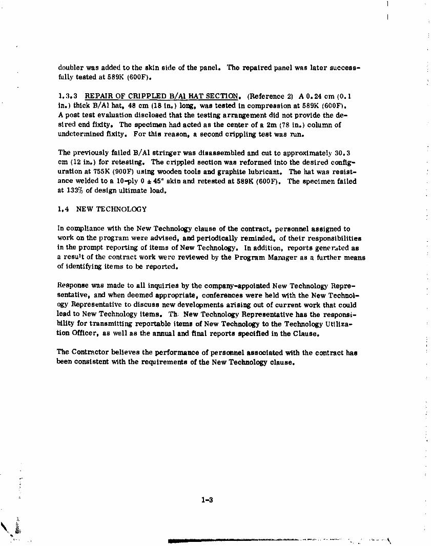
Six sets of specimens were selected for repair and subsequent re-testing. Selection of the specimens was based on the type of specimen, nature of the required repair, and the availability of previous test history. Repairs were made using, where applic- able, the ground rules established in Section 2. Photographic records were main- tained of specimens before, during, and after repair and subsequent re-testing. Attempts were made to test the repaired specimens under the same conditions used in the original testing.
3.1 SANDWICH BEAM TEST
A sandwich beam specimen was designed o~iginally :o demonstrate the strength of boron/aluminum ( B / A ~ ) when used as face sheet material on a honeycomb sandwich (Reference 9). The sandwich beam test enabled the face sheets to develop the highest possible strength due to both the stabilizing action of the core and the introduction of uniform loads.
The original specimen configuration is shown in Figure 3-1. The overall dimensions of the beam were 30.1 by 5.0 by 2.5 cm (12 by 2 by 1 in.). The load introduction tabs were made from 6061-T6 aluminum. The compression skin was made from 6Al-4V tit,uliur,l, the core from 3.1 mm (0.125 in. ) cell diameter by 0.06 mm (0.0023 in. ) thick aluminum honeycomb, and the tension skin from a 0.51 mm (0.020 In. ) thic!mess of 0.1 mm (4.0 mil) boron reinforced aluminum. The panel was bond4 together using FM-123 adhesive. It was assumed that a facing sheet tensile stress of 1207 MPa (175 ksi) would be developed; using this as the design value, a failure load of 13.7 l:N (3090 Ib) was anticipated. The specimeil failed by a tensile fracture of the B/Al skin; the :~cturrl failure load was 15.8 kN (3545 lb), which corresponds to a tensile s t ress of 1300 MPa (189.5 ksi) in the tension akin.
The specimen, shown in the damaged condition in Figure 3-2, was selected for this program because i t represents a severely damaged skin section.
The repair splice, consisting of a 0.76 mm (0.030 in. ) thick section of 0.1 mm (4 mil) unidirectional B/A1, was adhesively bonded to the 0.51 mm (0.020 in.) thick B / A ~ skin with FM-123 adhesive, The splice section was 15.2 cm (6 in.) in length and con- formed to the l/t ratio outlined in Section 2. The beam, prior to bcnding, was strait- ened as much a s possible a t room temperature using a flat press. A capillary adhes- ive, Hysol 9313, was used on the honeycomb a t cmck surfaces and at the titanium/ honeycomb interface. This adhesive was used to strengthen the honeycomb core and the titanium compression skin/aluminum honeycomb core interface where separation had occurred during initial testing. The repaired beam with the splice in place i s shown in Figure 3-3.
3-1


range, there was no permanent deformation in the tubes. There is, however, always a chance that thin-walled tubes could he crushed during service or due to abusive handling. To simulate this abusive handlkg, the tubes were crashed in a vise. Photo- graphs showing the tubes before and after the damage a r e presented in Figures 3-5 and 3-6. The damaged tubes were then tested in the same fixture used for initial testing. The results, shown in Table 3-2, indicate a decrease in elastic strength of approxi- mately 28%.
The two damaged B / A ~ tubes were repaired by reforming the damaged portions at 788K (950F). The re-forming die consisted of two steel blocks, each with a groove 1.27 cm (0.5 in.) in radius, machined on facing surfaces. The blocks were sufficiently long to completely cover the damaged area of the tubes. Originally, aluminum dies were tried; however, they were not sufficiently strong to reform the tubes, but instead yielded under pressure.
Both the steel blocks and the t u b s were coated with Everlube Corporation's T-50 graphite lubricant to minimize friction during forming. The steel blocks were exter- nally heated to 788K (950F) in a furnace and then clamped around a tube. The clamps were slowly tightened to bring the tube back to its original roundness. Forming was continued until the temperature of the steel dies dropped below 505K (450F), a t which point the blocks were reheated and the operation repeated. Thermocouples mounted at each end of the tube indicated that the temperature at the tube ends did not r ise above 505K (450F); therefore, the soldered end caps were not disturbed during repair.
In actual field repairs of this type (for tubes crushed during abusive handling), an ex- ternal heating unit could be locally applied to the steel dies, and the tubes repaired in situ. - An example of this technique was demonstrated when a 3.8 cm ( 1.5 in, ) diameter tube, similar to those to be used in the mid-fuselage of the Space Shuttle, was repaired. This tube had been deformed during autoclave diffusion bonding because of defective tooling. The tube was formed to its design shape in a manner similar to that described above.
Figure 3-7 shows the two repaired test specimens a s well a s the repaired mid-fuselage tube.
t f The rcepaired tubes were then re-tested in the same manner as was used in initial test- t F ing. The results a r e reported in Table 3-3. Although the buckling loads a r e greater
for the repaired tubes than for the damaged tubes (by 8 to lm), they a r e still less than the initial buckling loads for the undamaged tubes (by about 20%). This indicated that reforming of the damaged portions of the tube did not constitute an acceptable repair; therefore, the two B/A~ tubes were repaired again using thin etainless-ateel sheet material wrapped twice around the periphery of the tubes and bonded in place using
5
type 2216 adhesive. The 63.5 cm (26 in.) long tube had 'two strips of 3.8 cm (1,5 in.) 2 dl


Figure 3-7. Crushed B/AI 'rubes Repaired by forming a t 7881; (950F) (137203)
Tablc 3-3. Elastic Ruckling of Repai red B / A ~ 'I'ubcs --
Buckling Load Buckling Load Buckling Load Initial Damaged Repaired Wrap Repaired Weight
Tube Length Buckling Load 'hbes Tubes 'I'u be s Gain cm (in.) L/D k~ (lb) k~ (lb) la (lb) kN ( lb) (%
63.5 25 25.4 37.H 8500 26.7 (id00 31.7 7100 32.7 7400 G
wide by 0.15 mm (0.006 in.) thick stainless-stecl foil wrapped around the tuk twice and adhesively bonded and cured nt 3331.; (140E') for one hour. The foils were scparatcd by 2.54 cm (1.0 in.) a s shown in Figure 3-8.
The weight of the tube before the repair was 253 grams. The weight of the tube aftcr the repair was 268 grams, for a 6T weight gain. The 76.2 cm (30 in. ) long tube was similarly repaired, but consisted of a 10.2 cm (4 in.) long by 0.15 mm (0.006 in.) thick stainless-steel sheet bondcd at the centcr of the tube a s shown in Figure 3-8. The weight before repair was 257 grams. The weight after repair was 286 grams for a 11% weight gain.
After the stainless-steel wrap repairs were madc, thc tubes were again re-tested for txlckling strength; the results are reported in Table 3-3. The stainless-steel wrap repair resulted in an additional improvement in the buckling strength capability of the B/A1 tubes; however, the buckling strength i s still less than was initially obtained for the undamaged tubes (by 10 t o 13%). I t i s believed that with minor modifications the wrap repair method i s capable of restoring full buckling strength capabilities to damaged B / A ~ tubes.
3-7


Xrza A r w .001# C * 9 s STOL -6- ew cur w euo LYP I' C,V#I O I I I CCI 'YO~CI
FWm 3-9 eet Strixger Speaimsn B E ~ ~ D U C I B I L ~ T Y OF !dB
L- mIN.AL PAGE I8 POOR 3-9 C..


SECTION 4
CONCLUSIONS AND RECOMMENDATIONS
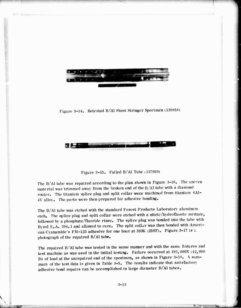
The program has demonstrated that boron/aluminum (B/A1) structures can be success- fully repaired with techniques similar to thoee currently used for conventional materi- als. Repair materials consisted of aluminum, titanium, steel, resin composites, o r B/Al, and repair techniques included adhesive bonding, mechanical fastening, and re- forming. Demonstration of the repair techniques were performed on the seven speci- men8 listed in Table 4-1.
Table 1-1. Summary of Repairability Results .----- ----
Specimen Weight Change % Load Change % -.- --.-- -- - - - -. . A --- .. . - - - . -- -
Sandwich Beam + 6.5 + 16.5
B/Al Tube (63.5 cm long) + 6 - 13 B/Al Tube (76.2 cm long) + 11 - 10
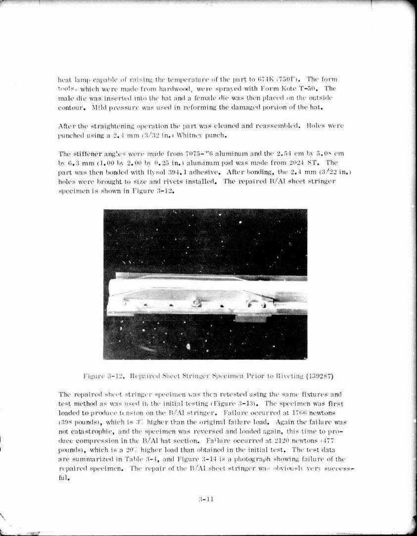
Sheet Stringer + 12 + 20
B/AI Tube ( 1 m long) + 15 + 76
Web Splice + 4 + 58
Tension Field Panel + 10 + 4 1 - -- Average 9 27
The average weight penalty incurred for these specimens was 9%: however, this result- ed in a performance increase over the as-fabricated specimens of 27%.
In addition to demonstrating repairability techniques , this program has served fo identify the "weak link" in the selected components; by repairing these areas , the composite structures were capable of higher performance than originally demonstrated. This points out the need for further work to develop optimum designs s o that greater advan- tage can be taken of the light weight and high performance of B/AI components.
The program also demonstrated that the 'shelf-life' of B/Al is similar to that of other metals. The specimens eelected for this program were from two to seven years old, and had been left in an unprotected state after their initial teet. No deleterious effects euch a s corrosion damage, damage from residual s t reeres , o r fiber matrix interaction were observed, thus giving increased confidence and cmdlbillty to the use of B/A1 composites.

Based on the results of this program (including those reeults discussed in References 1, 2, and 7), it is recommended that B/Al etructures be considered wher. high 1o:td intensities will be encountered. The fabrication can be accomplished with todqy's tech- nology and existing shop equipment and personnel. Using sheet metal fabrication tnch- niques, these composite etructures can be fabricated at a reasonable cost. If damaged in service the components can be readily repaired using simple repair techniques.

SECTION 5
REFERENCES
1. Miller, M. F., Christian, J. L., and Wennhold, W. F . , Design, Manufacture, Development, Test. and Evaluation of Boron./Aluminum Structural Components
---.. ----. -- - - -- for Space Shuttle, Volume I, Design and Analysis, GDCA-DBG73-006, NASA Contract NASH-27738, ~ u g u s t 1973.
2. Miller, M. F., Christian, J. L., and Wennhold, W. F., Design, Manufacture, -- Development, -- Test, and Evaluation - of Boron/Aluminum - Structural Components for Space Shuttle, Volume 11, hfnterials and Processing, GDCA-DBG73-006, ---- NASA Contract NASB-27738, August 1973.
3. Schaefer, W. H., Christian, J. L. , e t a l , Evaluation of the Structural Behavior of Filament Reinforced Metal Matrix Composites, AFML-TR-69-36, Ja ruary 1969.
4. Schaefer, U'. H., Aluminum-Boron F-106 Engine Access Door Design and Test Evaluation, Convair Aerospace Mvlsion Report GDC-ERR-I ;~~ , August 1970.
5 . Schaefer, W. H, , Wennhold, W. , e t 81, Composite Fuselage Development, Convair-San Diego report to General Dynamics, Fort Worth, for Air Force Contract F33C15-70-C-1494, 1969.
6. Forest , J. D., e t al , Advanced Compoelte Applications for Spacecraft and hlis- - s i les . Volume 1 - Structural Develo~ment. Volume 11 - Material ~evelo~men!. - AFML-TR-71-186, March 1973.
7. Spier, E. E., and Miller, M. F., Design, Manufacture, Development, Test , arx! -- .- - . . . - .- - -- - Evnltiation of ~ r o n / A l u m i n u m Stru&ral Components for Space Shuttle, Volume 1 I I , T e b t ~ n a l ~ ~ i a ~ ~ ~ ~ 7 3 - 0 0 6 , NASA Contract NAS8-27738, February 1974.
8. Wennhold, W. F. , Evaluation of a Metal Fuselage Panel Selective'ry Reinforced - with Filamentary Composites fo r Space Shuttle Applications, NASA Contract NAS1-10766, November 1973.
9. Mille* , M. F, Schaefer, W, H. , ad Weieinger, M, D. , Development of Improved Metal Matrix Fabrication Techniques for Aircraf t Stmatures , AFML-TR-71-181, July 1971.


![IES LM-79-08 TEST REPORT - LED Lighting Manufacture...Test Result [Integrating Sphere System] Total operating time for integrating sphere test: 1.0 hour Test orientation: Base Up Photometric](https://img.pdfslide.us/doc/110x75/5fc6ed08233730757d0ecc2a/ies-lm-79-08-test-report-led-lighting-manufacture-test-result-integrating.jpg)