Embed Size (px)
Citation preview

· Description Page 1.1
· Extruded Sections and Accessories Page 2.1 - 2.3
· Examples Page 3.10 - 3.90
Facade, Tray Panels SZ 20 - Horizontal Panel Layout
Part 2
Design Manual

Facade, Tray Panels SZ 20 - Horizontal Panel Layout
Description
Pro
du
ct ch
an
ge
s in
th
e se
nse
o
f a
te
ch
nica
l p
ro
gre
ss a
re
re
se
rve
d. A
ll a
dvice
re
co
mm
en
da
tio
n a
nd
in
fo
rm
atio
n is g
ive
n to
th
e b
est o
f o
ur kn
ow
le
dg
e b
ut w
ith
ou
t a
ny o
blig
atio
n o
n o
ur p
art 0
7/1
5
Part 2 1.1
With tray panel-elements based on the SZ-principle aesthetic and architectural
high-grade fascia claddings can be manufactured.
Based on construction principle with S-and Z-sections SZ 20 tray panels can
be installed fast and simple (tongue and groove principle).
The maximum horizontal and vertical width of gap is 20 mm.
The minimum horizontal and vertical width of gap depends on length of elements
and construction conditions.
The tray panel-elements are only fixed at each upper tray panel edge on the
vertical arranged substructure section (hat section). To this the Z-section
is fixed by stainless fascia screws to the hat sections.
The vertical arranged U-sections are not fixed to the sub-construction.
To ensure the thermal expansion due to the changes in temperature,
in the Z-section oblong-holes are to be arranged in the lateral fixing
points - depending on the length of the element.
To avoid clatter noise between the horizontal sections as a result of wind
loading it is recommended to use plastic clips in a distance of about 1 m.
With favourable loadings, SZ 20 panels can span large distances between
vertical supports.
The maximum element-measurements dependent on the available
production width and on the occuring wind loads.
Compared with solid metal tray panels, ALUCOBOND tray panels
offer the following advantages:
· ALUCOBOND panels are delivered ready for fitting with a stove-
lacquered surface finish (no subsequent painting required).
· Absolute surface flatness, even after folding.
· Folds can be made by hand (no folding machine required).
· High inherent strength of ALUCOBOND panels permits the use of
tray panels with flat surfaces (no auxiliary reinforcement
required for large elements).
· Low net weight facilitates simple and rapid installation.
· No anti-drumming coating required.
3
4
21.5
34
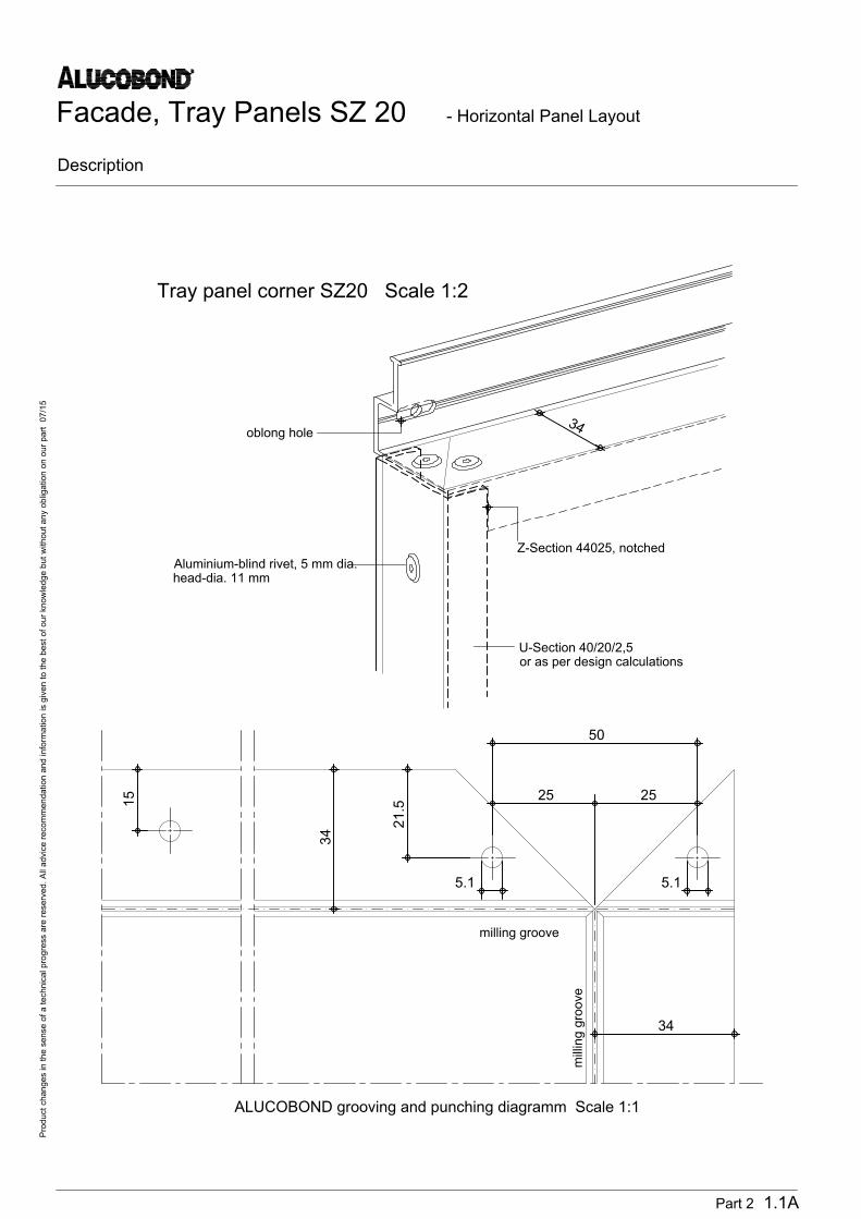
50
25 25
15
34
5.1 5.1
Z-Section 44025, notched
oblong hole
Aluminium-blind rivet, 5 mm dia.
head-dia. 11 mm
milling groove
milling groove
ALUCOBOND grooving and punching diagramm Scale 1:1
U-Section 40/20/2,5
or as per design calculations
Tray panel corner SZ20 Scale 1:2
Facade, Tray Panels SZ 20 - Horizontal Panel Layout
Description
Pro
du
ct ch
an
ge
s in
th
e se
nse
o
f a
te
ch
nica
l p
ro
gre
ss a
re
re
se
rve
d. A
ll a
dvice
re
co
mm
en
da
tio
n a
nd
in
fo
rm
atio
n is g
ive
n to
th
e b
est o
f o
ur kn
ow
le
dg
e b
ut w
ith
ou
t a
ny o
blig
atio
n o
n o
ur p
art 0
7/1
5
Part 2 1.1A

6
y
y
48
.5
y
y
y
y
xx
xx
xx
40.5
31
7
40
27.6
6
46
18
.7
71
.7
25
24
50
15
-2
0
34
.5
27
.5
30
3.5
3
3
6
2
8
7
3
4
5
7
1
4
2
Assembly Scale. 1:2
Facade, Tray Panels SZ 20 - Horizontal Panel Layout
Extruded Sections and Accessories
On the CD "Architecture in Detail" you`ll find in the the menu "Processing" a link to open the supplier addresses
Pro
du
ct ch
an
ge
s in
th
e se
nse
o
f a
te
ch
nica
l p
ro
gre
ss a
re
re
se
rve
d. A
ll a
dvice
re
co
mm
en
da
tio
n a
nd
in
fo
rm
atio
n is g
ive
n to
th
e b
est o
f o
ur kn
ow
le
dg
e b
ut w
ith
ou
t a
ny o
blig
atio
n o
n o
ur p
art 0
7/1
5
1
2
3
4
ALUCOBOND
Z-Section 40 025, weight 0,727 kg/m periphery 258 mm
Ix = 8,12 cm , Wx = 2,20 cm³ , Iy = 6,80 cm , Wy = 2,42 cm³
S-Section 44 024, weight 0,667 kg/m periphery 251 mm
Ix = 3,21 cm , Wx = 1,68 cm³ , Iy = 5,30 cm , Wy = 2,28 cm³
Extruded section 44 026 (starter), weight 0,625 kg/m periphery 233 mm
Ix = 4,58 cm , Wx = 1,25 cm³ , Iy = 2,13 cm , Wy = 0,75 cm³
Part 2 2.1
4 4
4
4 4
4

Assembly Scale. 1:2
hooked in hat section
30
5,4
36 30
96
5,4
1,6
50
2
50
y
15
-2
0
3
6
2
8
7
3
4
5
7
1
y
x x
2
5
3
Facade, Tray Panels SZ 20 - Horizontal Panel Layout
Extruded Sections and Accessories
On the CD "Architecture in Detail" you`ll find in the the menu "Processing" a link to open the supplier addresses
Pro
du
ct ch
an
ge
s in
th
e se
nse
o
f a
te
ch
nica
l p
ro
gre
ss a
re
re
se
rve
d. A
ll a
dvice
re
co
mm
en
da
tio
n a
nd
in
fo
rm
atio
n is g
ive
n to
th
e b
est o
f o
ur kn
ow
le
dg
e b
ut w
ith
ou
t a
ny o
blig
atio
n o
n o
ur p
art 0
7/1
5
5
6
7
8
Extruded hat section 35 953, weight 1,070 kg/m periphery 405 mm
Ix = 16,31 cm , Wx = 5,81 cm³ , Iy = 28,08 cm , Wy = 5,85 cm³
Plastic clip SZ 20 (Length: 40 mm)
Aluminium-blind rivet, with stainless steel mandrel, 5 mm dia., head-dia. 11 mm
Rivetable thickness = total material thickness plus 2 mm
Self-tapping screw or self drilling screw
Part 2 2.2
4 4

Extruded aluminium sections
for System SZ 20 and plastic clip
Wall bracket/substructre
MO2061
44024
44025
44026 35953
Alu-blind-rivet with painted head
with stainless steel mandrell
Dia. 5 mm, head-dia. 11 or 14 mm
Plastic board
for thermal separation
of wall bracket
Fixing of tray panels to sub-structure
Self drilling screws, stainless steel
with stainless steel sealing washer Ø 14 mm
Self tapping screw, cylinder head,
stainless steel, with stainless steel
sealing washer Ø 14 mm
Verbindungsmittel der Tragprofile mit den
Wandhaltern
- EJOT self drilling screw JT4-3H/5-5,5x19
- HILTI self drilling screw S-AD 01 S 5,5x19
- SFS self drilling screw SLA5/4-6-S4-6,0x19
- EJOT
- self drilling screw JT3-6-5,5x25-E14
- self tapping screw JZ3-ZT-6,3x19-E14
- HILTI
- self drilling screw S-MD 33 PS 5,5x22
- self drilling screw S-MD 31 PS 5,5x22
- SFS
- self drilling screw SX5-S14-5,5x26
Facade, Tray Panels SZ 20 - Horizontal Panel Layout
Extruded Sections and Accessories
On the CD "Architecture in Detail" you`ll find in the the menu "Processing" a link to open the supplier addresses
Pro
du
ct ch
an
ge
s in
th
e se
nse
o
f a
te
ch
nica
l p
ro
gre
ss a
re
re
se
rve
d. A
ll a
dvice
re
co
mm
en
da
tio
n a
nd
in
fo
rm
atio
n is g
ive
n to
th
e b
est o
f o
ur kn
ow
le
dg
e b
ut w
ith
ou
t a
ny o
blig
atio
n o
n o
ur p
art 0
7/1
5
Part 2 2.3
7
9'
8
5
3
4
1
6
3'
2
9
6'
3.2
Part 2 3.1
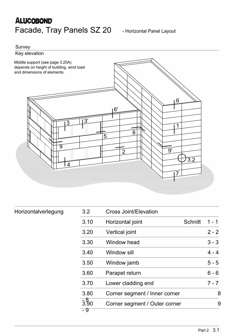
3.2 Cross Joint/Elevation
3.10 Horizontal joint Schnitt 1 - 1
3.20 Vertical joint 2 - 2
3.30 Window head 3 - 3
3.40 Window sill 4 - 4
3.50 Window jamb 5 - 5
3.60 Parapet return 6 - 6
3.70 Lower cladding end 7 - 7
3.80 Corner segment / Inner corner 8
- 8
3.90 Corner segment / Outer corner 9
- 9
Horizontalverlegung
Facade, Tray Panels SZ 20 - Horizontal Panel Layout
Survey
Key elevation
Middle support (see page 3.20A)
depends on height of building, wind load
and dimensions of elements.
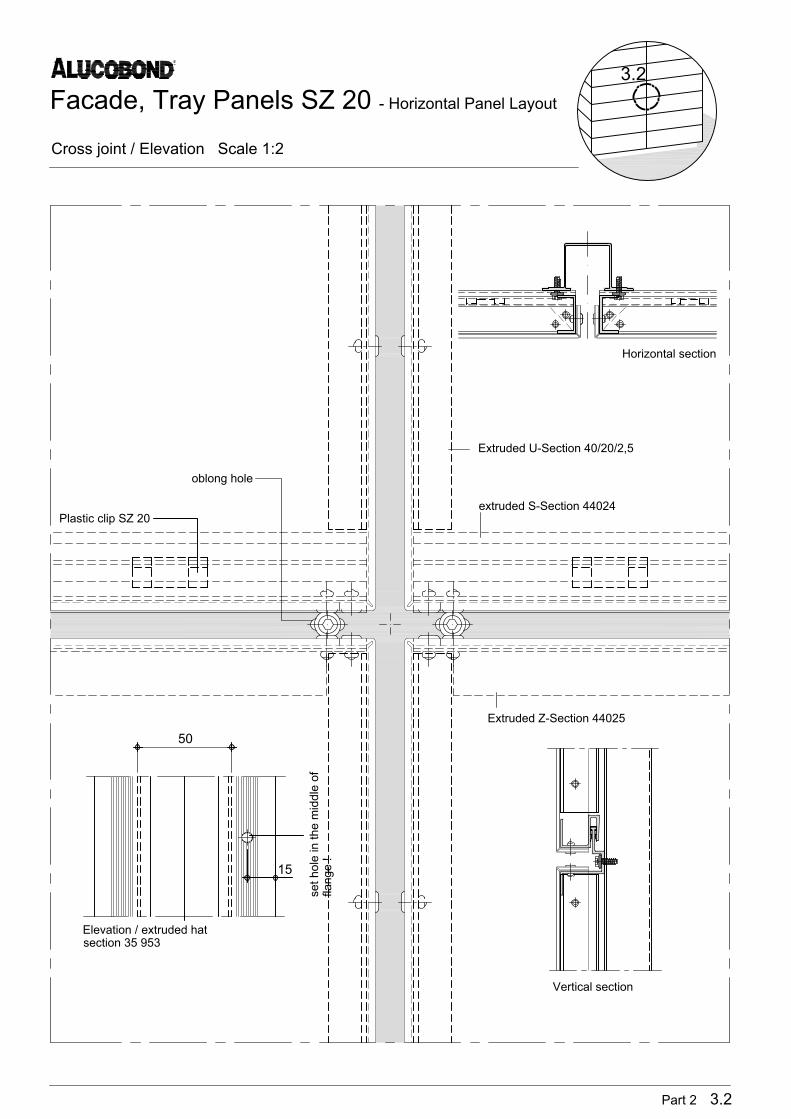
15
50
Horizontal section
Elevation / extruded hat
section 35 953
Vertical section
se
t h
ole
in
th
e m
id
dle
o
f
fla
ng
e !
Plastic clip SZ 20
oblong hole
Extruded U-Section 40/20/2,5
extruded S-Section 44024
Extruded Z-Section 44025
Part 2 3.2
Facade, Tray Panels SZ 20 - Horizontal Panel Layout
Cross joint / Elevation Scale 1:2
3.2

4
10
9
11
8
7
6
3
5
5
2
12
1
grid
grid
Facade, Tray Panels SZ 20 - Horizontal Panel Layout
Horizontal Joint (Section 1-1) Scale 1:2
Pro
du
ct ch
an
ge
s in
th
e se
nse
o
f a
te
ch
nica
l p
ro
gre
ss a
re
re
se
rve
d. A
ll a
dvice
re
co
mm
en
da
tio
n a
nd
in
fo
rm
atio
n is g
ive
n to
th
e b
est o
f o
ur kn
ow
le
dg
e b
ut w
ith
ou
t a
ny o
blig
atio
n o
n o
ur p
art 0
1/1
5
9
10
11
8
71
2
3
4
5
6
Part 2 3.10
12
ALUCOBOND Self-tapping screw or self drilling screw
Extruded S-Section 44024 Aluminium-blind rivet
Extruded Z-Section 44025 Extruded Al-liner
Plastic clip SZ 20 Wall bracket
Extruded U-Section 40/20/2,5 Plastic board (thermal separation)
Extruded hat section 35 953 Self drilling screw
1
6

11
9
10
12
4
5
2
3
6
7
gridgrid
1
8
Facade, Tray Panels SZ 20 - Horizontal Panel Layout
Vertical Joint / with Middle Support (Section 2'-2') Scale 1:2
Pro
du
ct ch
an
ge
s in
th
e se
nse
o
f a
te
ch
nica
l p
ro
gre
ss a
re
re
se
rve
d. A
ll a
dvice
re
co
mm
en
da
tio
n a
nd
in
fo
rm
atio
n is g
ive
n to
th
e b
est o
f o
ur kn
ow
le
dg
e b
ut w
ith
ou
t a
ny o
blig
atio
n o
n o
ur p
art 0
1/1
5
Part 2 3.20A
9
10
11
8
71
2
3
4
5
6 12
ALUCOBOND Self-tapping screw or self drilling screw
Extruded S-Section 44024 Aluminium-blind rivet
Extruded Z-Section 44025 Extruded Al-liner
Plastic clip SZ 20 Wall bracket
Extruded U-Section 40/20/2,5 Plastic board (thermal separation)
Extruded hat section 35 953 Self drilling screw
5
2

65
8
3
7
8
4
2
10
9
1
Facade, Tray Panels SZ 20 - Horizontal Panel Layout
Horizontal Joint (Section 1-1) Scale 1:2
Pro
du
ct ch
an
ge
s in
th
e se
nse
o
f a
te
ch
nica
l p
ro
gre
ss a
re
re
se
rve
d. A
ll a
dvice
re
co
mm
en
da
tio
n a
nd
in
fo
rm
atio
n is g
ive
n to
th
e b
est o
f o
ur kn
ow
le
dg
e b
ut w
ith
ou
t a
ny o
blig
atio
n o
n o
ur p
art 0
1/1
5
Part 2 3.31
9
10
8
71
2
3
4
5
6
ALUCOBOND Self-tapping screw or self drilling screw
Extruded S-Section 44024 Aluminium-blind rivet
Extruded Z-Section 44025 Extruded window connecting section 38 464
Plastic clip SZ 20 Reveal
Extruded U-Section 40/20/2,5
Extruded hat section 35 953
3
3'

6
5
8
3
9
9
4
7
10
2
1
Facade, Tray Panels SZ 20 - Horizontal Panel Layout
Window Head (Section 3-3, Area of Reveal) Scale 1:2
Pro
du
ct ch
an
ge
s in
th
e se
nse
o
f a
te
ch
nica
l p
ro
gre
ss a
re
re
se
rve
d. A
ll a
dvice
re
co
mm
en
da
tio
n a
nd
in
fo
rm
atio
n is g
ive
n to
th
e b
est o
f o
ur kn
ow
le
dg
e b
ut w
ith
ou
t a
ny o
blig
atio
n o
n o
ur p
art 0
1/1
5
9
10
8
71
2
3
4
5
6
Part 2 3.30
ALUCOBOND Self-tapping screw or self drilling screw
Extruded S-Section 44024 Aluminium-blind rivet
Extruded Z-Section 44025 Extruded window connecting section 38 464
Plastic clip SZ 20 Reveal
Extruded U-Section 40/20/2,5
Extruded hat section 35 953
3
3'

6
5
8
3
4
7
11
2
9
Re
ma
rk: U
pp
er w
eb
o
f se
ctio
n 4
4 0
25
is to
b
e sh
orte
ne
d (e
le
me
nt o
f re
ve
al)!
10
8
1
Facade, Tray Panels SZ 20 - Horizontal Panel Layout
Window Head (Section 3-3, Area of Reveal) Scale 1:2
Pro
du
ct ch
an
ge
s in
th
e se
nse
o
f a
te
ch
nica
l p
ro
gre
ss a
re
re
se
rve
d. A
ll a
dvice
re
co
mm
en
da
tio
n a
nd
in
fo
rm
atio
n is g
ive
n to
th
e b
est o
f o
ur kn
ow
le
dg
e b
ut w
ith
ou
t a
ny o
blig
atio
n o
n o
ur p
art 0
1/1
5
Part 2 3.32
9
10
8
71
2
3
4
5
6
ALUCOBOND Self-tapping screw or self drilling screw
Extruded S-Section 44024 Aluminium-blind rivet
Extruded Z-Section 44025 Extruded base section 44026
Plastic clip SZ 20 Extruded window connecting section 38 464
Extruded U-Section 40/20/2,5 Reveal
Extruded hat section 35 953
11
3
3'

10
119
Win
do
w sill, n
otch
ed
!
3
5
1
7
8
12
6
15
14
13
16
4
2
Facade, Tray Panels SZ 20 - Horizontal Panel Layout
Window Sill (Section 4-4) Scale 1:2
Pro
du
ct ch
an
ge
s in
th
e se
nse
o
f a
te
ch
nica
l p
ro
gre
ss a
re
re
se
rve
d. A
ll a
dvice
re
co
mm
en
da
tio
n a
nd
in
fo
rm
atio
n is g
ive
n to
th
e b
est o
f o
ur kn
ow
le
dg
e b
ut w
ith
ou
t a
ny o
blig
atio
n o
n o
ur p
art 0
1/1
5
Part 2 3.42
10
11
91
2
3
4
5
6
12
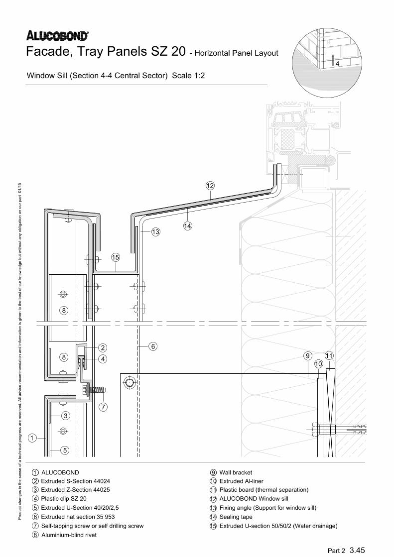
ALUCOBOND Wall bracket
Extruded S-Section 44024 Extruded Al-liner
Extruded Z-Section 44025 Plastic board (thermal separation)
Plastic clip SZ 20 Window sill-shaped aluminium sheet
Extruded U-Section 40/20/2,5 Side folding (window sill)
Extruded hat section 35 953 Folded Al-sheet (water drainage)
Self-tapping screw or self drilling screw Fixing angle (Support for window sill)
Aluminium-blind rivet Extruded window connecting section 38 464
7
13
8
14
15
Horizontal section see page 3.52
16
4
9
5
7
6
3
8
4
2
10
119
15
14
13
12
1
8
Facade, Tray Panels SZ 20 - Horizontal Panel Layout
Window Sill (Section 4-4 Central Sector) Scale 1:2
Pro
du
ct ch
an
ge
s in
th
e se
nse
o
f a
te
ch
nica
l p
ro
gre
ss a
re
re
se
rve
d. A
ll a
dvice
re
co
mm
en
da
tio
n a
nd
in
fo
rm
atio
n is g
ive
n to
th
e b
est o
f o
ur kn
ow
le
dg
e b
ut w
ith
ou
t a
ny o
blig
atio
n o
n o
ur p
art 0
1/1
5
Part 2 3.45
10
11
91
2
3
4
5
6
12
ALUCOBOND Wall bracket
Extruded S-Section 44024 Extruded Al-liner
Extruded Z-Section 44025 Plastic board (thermal separation)
Plastic clip SZ 20 ALUCOBOND Window sill
Extruded U-Section 40/20/2,5 Fixing angle (Support for window sill)
Extruded hat section 35 953 Sealing tape
Self-tapping screw or self drilling screw Extruded U-section 50/50/2 (Water drainage)
Aluminium-blind rivet
7
13
8
14
15
4
9
5
7
11
10
9
8
1
14
3
15
3
2
4
13
16
12
6
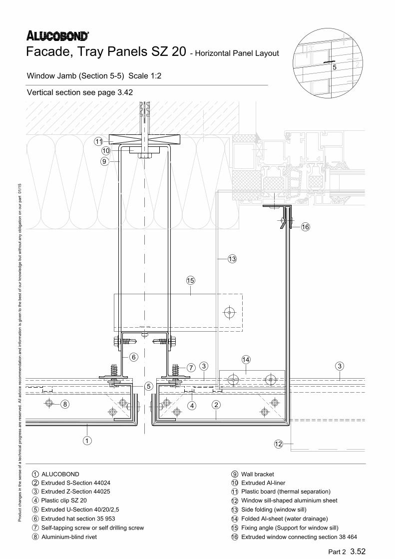
Facade, Tray Panels SZ 20 - Horizontal Panel Layout
Window Jamb (Section 5-5) Scale 1:2
Pro
du
ct ch
an
ge
s in
th
e se
nse
o
f a
te
ch
nica
l p
ro
gre
ss a
re
re
se
rve
d. A
ll a
dvice
re
co
mm
en
da
tio
n a
nd
in
fo
rm
atio
n is g
ive
n to
th
e b
est o
f o
ur kn
ow
le
dg
e b
ut w
ith
ou
t a
ny o
blig
atio
n o
n o
ur p
art 0
1/1
5
Part 2 3.52
10
11
91
2
3
4
5
6
12
ALUCOBOND Wall bracket
Extruded S-Section 44024 Extruded Al-liner
Extruded Z-Section 44025 Plastic board (thermal separation)
Plastic clip SZ 20 Window sill-shaped aluminium sheet
Extruded U-Section 40/20/2,5 Side folding (window sill)
Extruded hat section 35 953 Folded Al-sheet (water drainage)
Self-tapping screw or self drilling screw Fixing angle (Support for window sill)
Aluminium-blind rivet Extruded window connecting section 38 464
7
13
8
14
15
16
Vertical section see page 3.42
2
5
3'

6
7
11
10
9
8
1
14
3
15
3
2
4
13
16
12
5
Facade, Tray Panels SZ 20 - Horizontal Panel Layout
Window Jamb (Section 5-5) Scale 1:2
Pro
du
ct ch
an
ge
s in
th
e se
nse
o
f a
te
ch
nica
l p
ro
gre
ss a
re
re
se
rve
d. A
ll a
dvice
re
co
mm
en
da
tio
n a
nd
in
fo
rm
atio
n is g
ive
n to
th
e b
est o
f o
ur kn
ow
le
dg
e b
ut w
ith
ou
t a
ny o
blig
atio
n o
n o
ur p
art 0
1/1
5
Part 2 3.52A
10
11
91
2
3
4
5
6
12
ALUCOBOND Wall bracket
Extruded S-Section 44024 Extruded Al-liner
Extruded Z-Section 44025 Plastic board (thermal separation)
Plastic clip SZ 20 Window sill-shaped aluminium sheet
Extruded L-Section Side folding (window sill)
Extruded hat section 35 953 Folded Al-sheet (water drainage)
Self-tapping screw or self drilling screw Fixing angle (Support for window sill)
Aluminium-blind rivet Extruded window connecting section 38 464
7
13
8
14
15
16
Vertical section see page 3.42A
2
5
3'

3
2
4
5
7
6
8
9
10
11
1
12
6
Facade, Tray Panels SZ 20 - Horizontal Panel Layout
Parapet Return (Section 6-6) Scale 1:3
Pro
du
ct ch
an
ge
s in
th
e se
nse
o
f a
te
ch
nica
l p
ro
gre
ss a
re
re
se
rve
d. A
ll a
dvice
re
co
mm
en
da
tio
n a
nd
in
fo
rm
atio
n is g
ive
n to
th
e b
est o
f o
ur kn
ow
le
dg
e b
ut w
ith
ou
t a
ny o
blig
atio
n o
n o
ur p
art 0
1/1
5
Part 2 3.61
8
9
71
2
3
4
5
6
10
ALUCOBOND Self-tapping screw or self drilling screw
Extruded S-Section 44024 Self drilling screw
Extruded Z-Section 44025 Wall bracket
Plastic clip SZ 20 Extruded Al-liner
Extruded U-Section 40/20/2,5 Plastic board (thermal separation)
Extruded hat section 35 953 Fixing angle
11
12
Developed view of the corner
segments see section 3.1
8
2
5
6'

5
6
8
10
11
12
1
13
3
2
4
7
9
Facade, Tray Panels SZ 20 - Horizontal Panel Layout
Parapet Return (Section 6-6) Scale 1:3
Pro
du
ct ch
an
ge
s in
th
e se
nse
o
f a
te
ch
nica
l p
ro
gre
ss a
re
re
se
rve
d. A
ll a
dvice
re
co
mm
en
da
tio
n a
nd
in
fo
rm
atio
n is g
ive
n to
th
e b
est o
f o
ur kn
ow
le
dg
e b
ut w
ith
ou
t a
ny o
blig
atio
n o
n o
ur p
art 0
1/1
5
Part 2 3.61
8
9
7
1
2
3
4
5
6
10
ALUCOBOND Self drilling screw
Extruded S-Section 44024 Fixing angle
Extruded Z-Section 44025 Wall bracket
Plastic clip SZ 20 Extruded Al-liner
Extruded U-Section 40/20/2,5 Plastic board (thermal separation)
Extruded hat section 35 953 Fixing angle
Self-tapping screw or self drilling screw
11
12
Developed view of the corner
segments see section 3.1
1
6
13
11
3
7
5
6
1
86
10
9
4
2
Facade, Tray Panels SZ 20 - Horizontal Panel Layout
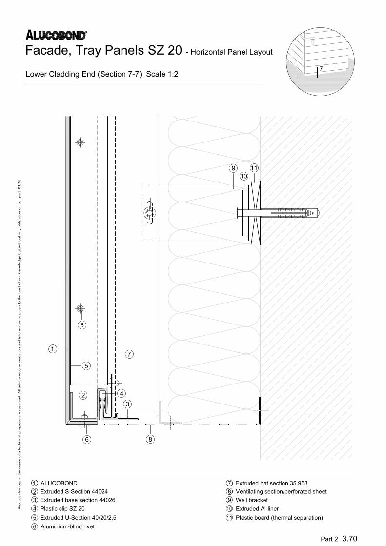
Lower Cladding End (Section 7-7) Scale 1:2
Pro
du
ct ch
an
ge
s in
th
e se
nse
o
f a
te
ch
nica
l p
ro
gre
ss a
re
re
se
rve
d. A
ll a
dvice
re
co
mm
en
da
tio
n a
nd
in
fo
rm
atio
n is g
ive
n to
th
e b
est o
f o
ur kn
ow
le
dg
e b
ut w
ith
ou
t a
ny o
blig
atio
n o
n o
ur p
art 0
1/1
5
9
10
11
8
71
2
3
4
5
6
Part 2 3.70
ALUCOBOND Extruded hat section 35 953
Extruded S-Section 44024 Ventilating section/perforated sheet
Extruded base section 44026 Wall bracket
Plastic clip SZ 20 Extruded Al-liner
Extruded U-Section 40/20/2,5 Plastic board (thermal separation)
Aluminium-blind rivet
7
9'

3
5
1
2
7
8
6
4
11
10
9
Facade, Tray Panels SZ 20 - Horizontal Panel Layout
Corner Segment/Inner Corner (Section 8-8) Scale 1:3
Pro
du
ct ch
an
ge
s in
th
e se
nse
o
f a
te
ch
nica
l p
ro
gre
ss a
re
re
se
rve
d. A
ll a
dvice
re
co
mm
en
da
tio
n a
nd
in
fo
rm
atio
n is g
ive
n to
th
e b
est o
f o
ur kn
ow
le
dg
e b
ut w
ith
ou
t a
ny o
blig
atio
n o
n o
ur p
art 0
1/1
5
Part 2 3.80
8
9
71
2
3
4
5
6
10
ALUCOBOND Self-tapping screw or self drilling screw
Extruded S-Section 44024 Self drilling screw
Extruded Z-Section 44025 Wall bracket
Plastic clip SZ 20 Extruded Al-liner
Extruded U-Section 40/20/2,5 Plastic board (thermal separation)
Extruded hat section 35 953
11
8
2
2'

11
10
9
7
5
8
6
3
4
2
1
Facade, Tray Panels SZ 20 - Horizontal Panel Layout
Corner Segment/Outer Corner (Section 9-9) Scale 1:3
Pro
du
ct ch
an
ge
s in
th
e se
nse
o
f a
te
ch
nica
l p
ro
gre
ss a
re
re
se
rve
d. A
ll a
dvice
re
co
mm
en
da
tio
n a
nd
in
fo
rm
atio
n is g
ive
n to
th
e b
est o
f o
ur kn
ow
le
dg
e b
ut w
ith
ou
t a
ny o
blig
atio
n o
n o
ur p
art 0
1/1
5
Part 2 3.90
8
9
71
2
3
4
5
6
10
ALUCOBOND Self-tapping screw or self drilling screw
Extruded S-Section 44024 Self drilling screw
Extruded Z-Section 44025 Wall bracket
Plastic clip SZ 20 Extruded Al-liner
Extruded U-Section 40/20/2,5 Plastic board (thermal separation)
Extruded hat section 35 953
11
3
9

10
9
8
6
7
5
4
3
2
1
Facade, Tray Panels SZ 20 - Horizontal Panel Layout
Corner Segment/Outer Corner (Section 9-9) Scale 1:3
Pro
du
ct ch
an
ge
s in
th
e se
nse
o
f a
te
ch
nica
l p
ro
gre
ss a
re
re
se
rve
d. A
ll a
dvice
re
co
mm
en
da
tio
n a
nd
in
fo
rm
atio
n is g
ive
n to
th
e b
est o
f o
ur kn
ow
le
dg
e b
ut w
ith
ou
t a
ny o
blig
atio
n o
n o
ur p
art 0
1/1
5
Part 2 3.91
8
9
71
2
3
4
5
6
10
ALUCOBOND Self drilling screw
Extruded S-Section 44024 Wall bracket
Extruded Z-Section 44025 Extruded Al-liner
Plastic clip SZ 20 Plastic board (thermal separation)
Extruded hat section 35953
Self-tapping screw or self drilling screw
7
9'
8
1
max. lever length depending on the windloads


![5 1,6 1,4 1,6 1 arXiv:1811.02473v1 [cond-mat.str-el] 6 Nov](https://img.pdfslide.us/doc/110x75/618116d1de1d3906bf1a5c99/5-16-14-16-1-arxiv181102473v1-cond-matstr-el-6-nov-.jpg)
![index [donar.messe.de] · PROFESSIONALI DA 1,6 A 3 KVA Applicazioni: • Local Area Networks (LAN) • CED ... Frequenza / Frequency 50/60 Hz ± 5% Uscita / Output Forma d’onda](https://img.pdfslide.us/doc/110x75/5c6ce96a09d3f246468b6c21/index-donarmessede-professionali-da-16-a-3-kva-applicazioni-local.jpg)