Embed Size (px)
Citation preview

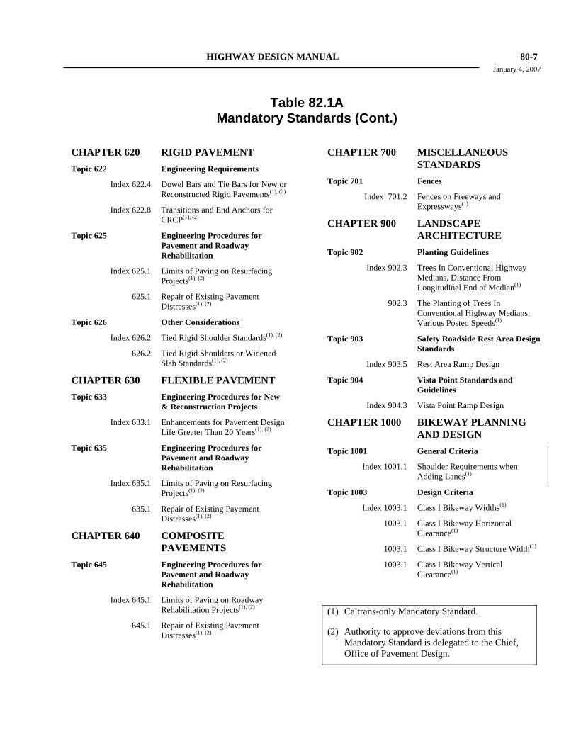
HIGHWAY DESIGN MANUAL 80-7 January 4, 2007
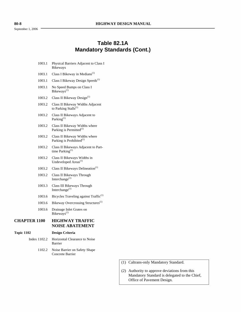
Table 82.1A
Mandatory Standards (Cont.) CHAPTER 620 RIGID PAVEMENT Topic 622 Engineering Requirements
Index 622.4 Dowel Bars and Tie Bars for New or Reconstructed Rigid Pavements(1), (2)
Index 622.8 Transitions and End Anchors for CRCP(1), (2)
Topic 625 Engineering Procedures for Pavement and Roadway Rehabilitation
Index 625.1 Limits of Paving on Resurfacing Projects(1), (2)
625.1 Repair of Existing Pavement Distresses(1), (2)
Topic 626 Other Considerations
Index 626.2 Tied Rigid Shoulder Standards(1), (2)
626.2 Tied Rigid Shoulders or Widened Slab Standards(1), (2)
CHAPTER 630 FLEXIBLE PAVEMENT Topic 633 Engineering Procedures for New
& Reconstruction Projects
Index 633.1 Enhancements for Pavement Design Life Greater Than 20 Years(1), (2)
Topic 635 Engineering Procedures for Pavement and Roadway Rehabilitation
Index 635.1 Limits of Paving on Resurfacing Projects(1), (2)
635.1 Repair of Existing Pavement Distresses(1), (2)
CHAPTER 640 COMPOSITE PAVEMENTS
Topic 645 Engineering Procedures for Pavement and Roadway Rehabilitation
Index 645.1 Limits of Paving on Roadway Rehabilitation Projects(1), (2)
645.1 Repair of Existing Pavement Distresses(1), (2)
CHAPTER 700 MISCELLANEOUS STANDARDS
Topic 701 Fences Index 701.2 Fences on Freeways and
Expressways(1)
CHAPTER 900 LANDSCAPE ARCHITECTURE
Topic 902 Planting Guidelines
Index 902.3 Trees In Conventional Highway Medians, Distance From Longitudinal End of Median(1)
902.3 The Planting of Trees In Conventional Highway Medians, Various Posted Speeds(1)
Topic 903 Safety Roadside Rest Area Design Standards
Index 903.5 Rest Area Ramp Design Topic 904 Vista Point Standards and
Guidelines Index 904.3 Vista Point Ramp Design
CHAPTER 1000 BIKEWAY PLANNING AND DESIGN
Topic 1001 General Criteria Index 1001.1 Shoulder Requirements when
Adding Lanes(1)
Topic 1003 Design Criteria
Index 1003.1 Class I Bikeway Widths(1)
1003.1 Class I Bikeway Horizontal Clearance(1)
1003.1 Class I Bikeway Structure Width(1)
1003.1 Class I Bikeway Vertical Clearance(1)
(1) Caltrans-only Mandatory Standard. (2) Authority to approve deviations from this
Mandatory Standard is delegated to the Chief, Office of Pavement Design.
80-8 HIGHWAY DESIGN MANUAL September 1, 2006
Table 82.1A
Mandatory Standards (Cont.)
1003.1 Physical Barriers Adjacent to Class I Bikeways
1003.1 Class I Bikeway in Medians(1)
1003.1 Class I Bikeway Design Speeds(1)
1003.1 No Speed Bumps on Class I Bikeways(1)
1003.2 Class II Bikeway Design(1)
1003.2 Class II Bikeway Widths Adjacent to Parking Stalls(1)
1003.2 Class II Bikeways Adjacent to Parking(1)
1003.2 Class II Bikeway Widths where Parking is Permitted(1)
1003.2 Class II Bikeway Widths where Parking is Prohibited(1)
1003.2 Class II Bikeways Adjacent to Part-time Parking(1)
1003.2 Class II Bikeways Widths in Undeveloped Areas(1)
1003.2 Class II Bikeways Delineation(1)
1003.2 Class II Bikeways Through Interchange(1)
1003.3 Class III Bikeways Through Interchange(1)
1003.6 Bicycles Traveling against Traffic(1)
1003.6 Bikeway Overcrossing Structures(1)
1003.6 Drainage Inlet Grates on Bikeways(1)
CHAPTER 1100 HIGHWAY TRAFFIC NOISE ABATEMENT
Topic 1102 Design Criteria Index 1102.2 Horizontal Clearance to Noise
Barrier 1102.2 Noise Barrier on Safety Shape
Concrete Barrier
(1) Caltrans-only Mandatory Standard. (2) Authority to approve deviations from this
Mandatory Standard is delegated to the Chief, Office of Pavement Design.
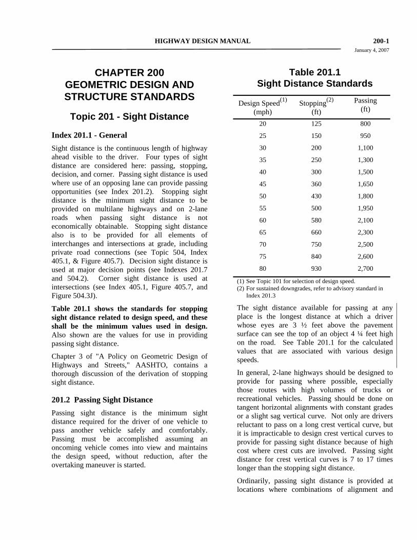
HIGHWAY DESIGN MANUAL 200-1 January 4, 2007
CHAPTER 200 GEOMETRIC DESIGN AND STRUCTURE STANDARDS
Topic 201 - Sight Distance
Index 201.1 - General Sight distance is the continuous length of highway ahead visible to the driver. Four types of sight distance are considered here: passing, stopping, decision, and corner. Passing sight distance is used where use of an opposing lane can provide passing opportunities (see Index 201.2). Stopping sight distance is the minimum sight distance to be provided on multilane highways and on 2-lane roads when passing sight distance is not economically obtainable. Stopping sight distance also is to be provided for all elements of interchanges and intersections at grade, including private road connections (see Topic 504, Index 405.1, & Figure 405.7). Decision sight distance is used at major decision points (see Indexes 201.7 and 504.2). Corner sight distance is used at intersections (see Index 405.1, Figure 405.7, and Figure 504.3J).
Table 201.1 shows the standards for stopping sight distance related to design speed, and these shall be the minimum values used in design. Also shown are the values for use in providing passing sight distance.
Chapter 3 of "A Policy on Geometric Design of Highways and Streets," AASHTO, contains a thorough discussion of the derivation of stopping sight distance.
201.2 Passing Sight Distance Passing sight distance is the minimum sight distance required for the driver of one vehicle to pass another vehicle safely and comfortably. Passing must be accomplished assuming an oncoming vehicle comes into view and maintains the design speed, without reduction, after the overtaking maneuver is started.
Table 201.1 Sight Distance Standards
Design Speed(1)
(mph) Stopping(2)
(ft) Passing
(ft)
20 125 800
25 150 950
30 200 1,100
35 250 1,300
40 300 1,500
45 360 1,650
50 430 1,800
55 500 1,950
60 580 2,100
65 660 2,300
70 750 2,500
75 840 2,600
80 930 2,700
(1) See Topic 101 for selection of design speed. (2) For sustained downgrades, refer to advisory standard in
Index 201.3
The sight distance available for passing at any place is the longest distance at which a driver whose eyes are 3 ½ feet above the pavement surface can see the top of an object 4 ¼ feet high on the road. See Table 201.1 for the calculated values that are associated with various design speeds.
In general, 2-lane highways should be designed to provide for passing where possible, especially those routes with high volumes of trucks or recreational vehicles. Passing should be done on tangent horizontal alignments with constant grades or a slight sag vertical curve. Not only are drivers reluctant to pass on a long crest vertical curve, but it is impracticable to design crest vertical curves to provide for passing sight distance because of high cost where crest cuts are involved. Passing sight distance for crest vertical curves is 7 to 17 times longer than the stopping sight distance.
Ordinarily, passing sight distance is provided at locations where combinations of alignment and
200-2 HIGHWAY DESIGN MANUAL January 4, 2007 profile do not require the use of crest vertical curves.
Passing sight distance is considered only on 2-lane roads. At critical locations, a stretch of 3- or 4-lane passing section with stopping sight distance is sometimes more economical than two lanes with passing sight distance.
Passing on sag vertical curves can be accomplished both day and night because headlights can be seen through the entire curve.
See Part 3 of the Manual on Uniform Traffic Control Devices (MUTCD) for criteria relating to the placement of barrier striping for no-passing zones. Note, that the passing sight distances shown in the MUTCD are based on traffic operational criteria. Traffic operational criteria are different from the design characteristics used to develop the values provided in Table 201.1 and Chapter 3 of AASHTO, A Policy on Geometric Design of Highways and Streets. The aforementioned table and AASHTO reference are also used to design the vertical profile and horizontal alignment of the highway. Consult the Headquarters (HQ) Traffic Liaison when using the MUTCD criteria for traffic operating-control needs.
Other means for providing passing opportunities, such as climbing lanes or turnouts, are discussed in Index 204.5. Chapter 3 of AASHTO, A Policy on Geometric Design of Highways and Streets, contains a thorough discussion of the derivation of passing sight distance.
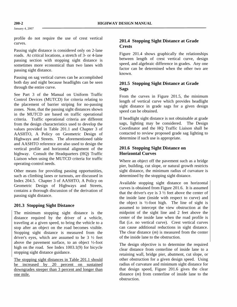
201.3 Stopping Sight Distance The minimum stopping sight distance is the distance required by the driver of a vehicle, traveling at a given speed, to bring the vehicle to a stop after an object on the road becomes visible. Stopping sight distance is measured from the driver's eyes, which are assumed to be 3 ½ feet above the pavement surface, to an object ½-foot high on the road. See Index 1003.1(9) for bicycle stopping sight distance guidance.
The stopping sight distances in Table 201.1 should be increased by 20 percent on sustained downgrades steeper than 3 percent and longer than one mile.
201.4 Stopping Sight Distance at Grade Crests Figure 201.4 shows graphically the relationships between length of crest vertical curve, design speed, and algebraic difference in grades. Any one factor can be determined when the other two are known.
201.5 Stopping Sight Distance at Grade Sags From the curves in Figure 201.5, the minimum length of vertical curve which provides headlight sight distance in grade sags for a given design speed can be obtained.
If headlight sight distance is not obtainable at grade sags, lighting may be considered. The Design Coordinator and the HQ Traffic Liaison shall be contacted to review proposed grade sag lighting to determine if such use is appropriate.
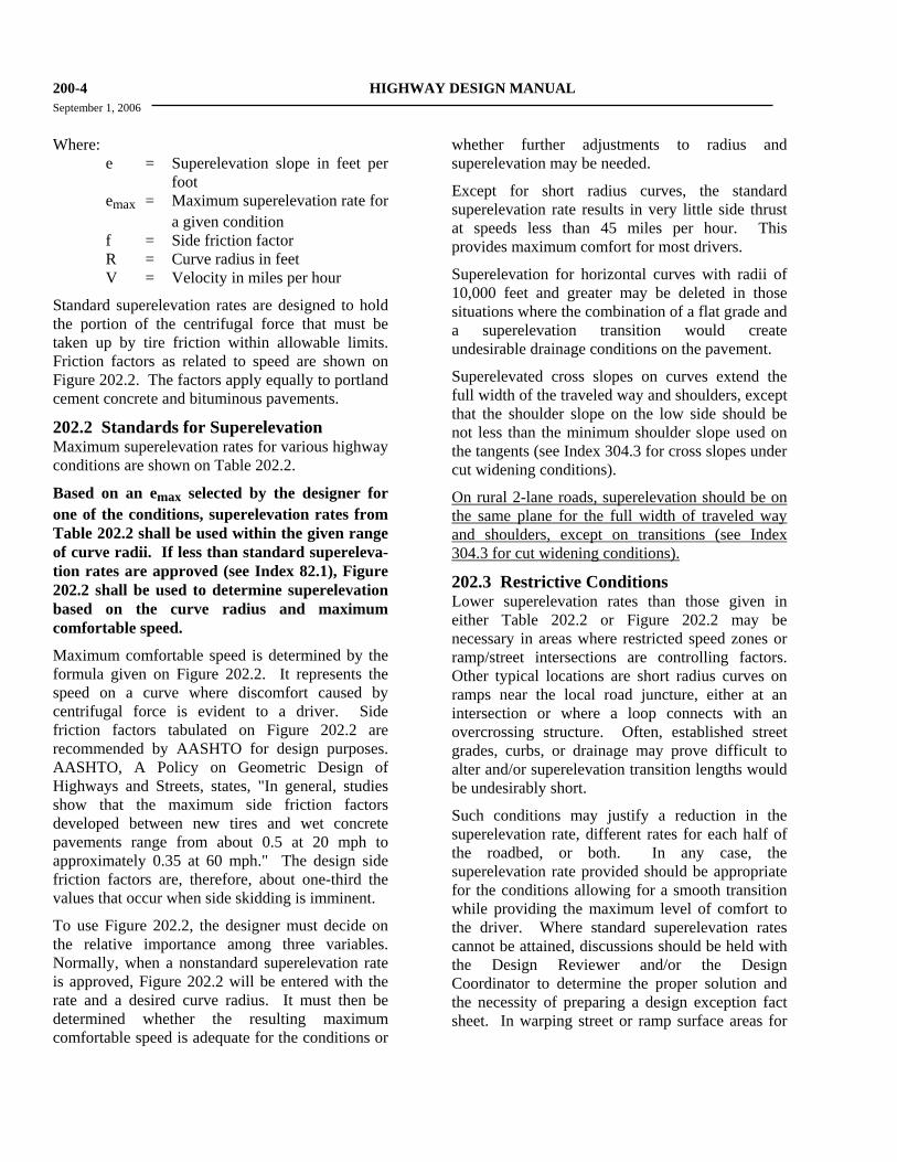
201.6 Stopping Sight Distance on Horizontal Curves Where an object off the pavement such as a bridge pier, building, cut slope, or natural growth restricts sight distance, the minimum radius of curvature is determined by the stopping sight distance.
Available stopping sight distance on horizontal curves is obtained from Figure 201.6. It is assumed that the driver's eye is 3 ½ feet above the center of the inside lane (inside with respect to curve) and the object is ½-foot high. The line of sight is assumed to intercept the view obstruction at the midpoint of the sight line and 2 feet above the center of the inside lane when the road profile is flat (i.e. no vertical curve). Crest vertical curves can cause additional reductions in sight distance. The clear distance (m) is measured from the center of the inside lane to the obstruction.
The design objective is to determine the required clear distance from centerline of inside lane to a retaining wall, bridge pier, abutment, cut slope, or other obstruction for a given design speed. Using radius of curvature and minimum sight distance for that design speed, Figure 201.6 gives the clear distance (m) from centerline of inside lane to the obstruction.
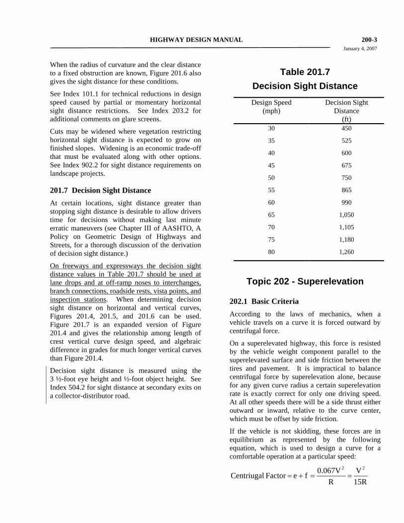
HIGHWAY DESIGN MANUAL 200-3 January 4, 2007 When the radius of curvature and the clear distance to a fixed obstruction are known, Figure 201.6 also gives the sight distance for these conditions.
See Index 101.1 for technical reductions in design speed caused by partial or momentary horizontal sight distance restrictions. See Index 203.2 for additional comments on glare screens.
Cuts may be widened where vegetation restricting horizontal sight distance is expected to grow on finished slopes. Widening is an economic trade-off that must be evaluated along with other options. See Index 902.2 for sight distance requirements on landscape projects.
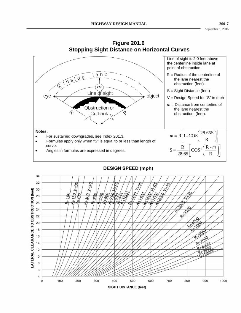
201.7 Decision Sight Distance At certain locations, sight distance greater than stopping sight distance is desirable to allow drivers time for decisions without making last minute erratic maneuvers (see Chapter III of AASHTO, A Policy on Geometric Design of Highways and Streets, for a thorough discussion of the derivation of decision sight distance.)
On freeways and expressways the decision sight distance values in Table 201.7 should be used at lane drops and at off-ramp noses to interchanges, branch connections, roadside rests, vista points, and inspection stations. When determining decision sight distance on horizontal and vertical curves, Figures 201.4, 201.5, and 201.6 can be used. Figure 201.7 is an expanded version of Figure 201.4 and gives the relationship among length of crest vertical curve design speed, and algebraic difference in grades for much longer vertical curves than Figure 201.4.
Decision sight distance is measured using the 3 ½-foot eye height and ½-foot object height. See Index 504.2 for sight distance at secondary exits on a collector-distributor road.
Table 201.7
Decision Sight Distance Design Speed
(mph) Decision Sight
Distance (ft)
30 450
35 525
40 600
45 675
50 750
55 865
60 990
65 1,050
70 1,105
75 1,180
80 1,260
Topic 202 - Superelevation
202.1 Basic Criteria According to the laws of mechanics, when a vehicle travels on a curve it is forced outward by centrifugal force.
On a superelevated highway, this force is resisted by the vehicle weight component parallel to the superelevated surface and side friction between the tires and pavement. It is impractical to balance centrifugal force by superelevation alone, because for any given curve radius a certain superelevation rate is exactly correct for only one driving speed. At all other speeds there will be a side thrust either outward or inward, relative to the curve center, which must be offset by side friction.
If the vehicle is not skidding, these forces are in equilibrium as represented by the following equation, which is used to design a curve for a comfortable operation at a particular speed:
15RV
R0.067Vfe Factor Centriugal
22
==+=
200-4 HIGHWAY DESIGN MANUAL September 1, 2006 Where:
e = Superelevation slope in feet per foot
emax = Maximum superelevation rate for a given condition
f = Side friction factor R = Curve radius in feet V = Velocity in miles per hour
Standard superelevation rates are designed to hold the portion of the centrifugal force that must be taken up by tire friction within allowable limits. Friction factors as related to speed are shown on Figure 202.2. The factors apply equally to portland cement concrete and bituminous pavements.
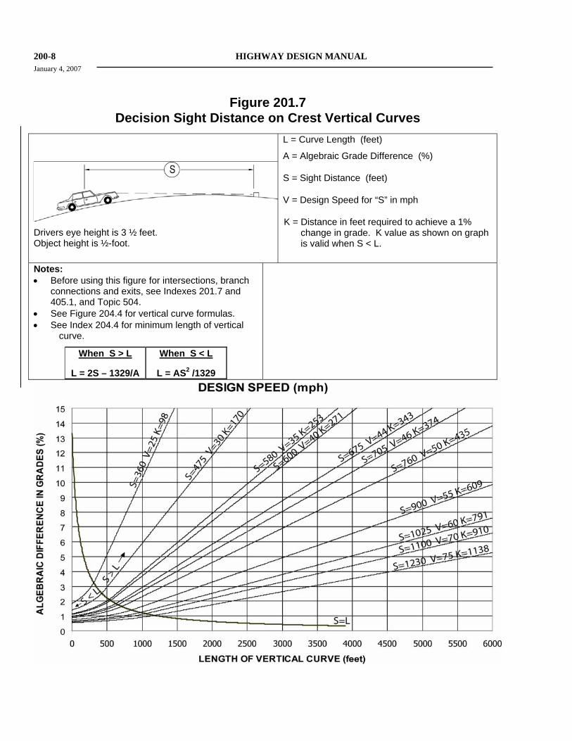
202.2 Standards for Superelevation Maximum superelevation rates for various highway conditions are shown on Table 202.2.
Based on an emax selected by the designer for one of the conditions, superelevation rates from Table 202.2 shall be used within the given range of curve radii. If less than standard supereleva-tion rates are approved (see Index 82.1), Figure 202.2 shall be used to determine superelevation based on the curve radius and maximum comfortable speed.
Maximum comfortable speed is determined by the formula given on Figure 202.2. It represents the speed on a curve where discomfort caused by centrifugal force is evident to a driver. Side friction factors tabulated on Figure 202.2 are recommended by AASHTO for design purposes. AASHTO, A Policy on Geometric Design of Highways and Streets, states, "In general, studies show that the maximum side friction factors developed between new tires and wet concrete pavements range from about 0.5 at 20 mph to approximately 0.35 at 60 mph." The design side friction factors are, therefore, about one-third the values that occur when side skidding is imminent.
To use Figure 202.2, the designer must decide on the relative importance among three variables. Normally, when a nonstandard superelevation rate is approved, Figure 202.2 will be entered with the rate and a desired curve radius. It must then be determined whether the resulting maximum comfortable speed is adequate for the conditions or
whether further adjustments to radius and superelevation may be needed.
Except for short radius curves, the standard superelevation rate results in very little side thrust at speeds less than 45 miles per hour. This provides maximum comfort for most drivers.
Superelevation for horizontal curves with radii of 10,000 feet and greater may be deleted in those situations where the combination of a flat grade and a superelevation transition would create undesirable drainage conditions on the pavement.
Superelevated cross slopes on curves extend the full width of the traveled way and shoulders, except that the shoulder slope on the low side should be not less than the minimum shoulder slope used on the tangents (see Index 304.3 for cross slopes under cut widening conditions).
On rural 2-lane roads, superelevation should be on the same plane for the full width of traveled way and shoulders, except on transitions (see Index 304.3 for cut widening conditions).
202.3 Restrictive Conditions Lower superelevation rates than those given in either Table 202.2 or Figure 202.2 may be necessary in areas where restricted speed zones or ramp/street intersections are controlling factors. Other typical locations are short radius curves on ramps near the local road juncture, either at an intersection or where a loop connects with an overcrossing structure. Often, established street grades, curbs, or drainage may prove difficult to alter and/or superelevation transition lengths would be undesirably short.
Such conditions may justify a reduction in the superelevation rate, different rates for each half of the roadbed, or both. In any case, the superelevation rate provided should be appropriate for the conditions allowing for a smooth transition while providing the maximum level of comfort to the driver. Where standard superelevation rates cannot be attained, discussions should be held with the Design Reviewer and/or the Design Coordinator to determine the proper solution and the necessity of preparing a design exception fact sheet. In warping street or ramp surface areas for
HIGHWAY DESIGN MANUAL 200-7 September 1, 2006
Figure 201.6 Stopping Sight Distance on Horizontal Curves
Line of sight is 2.0 feet above the centerline inside lane at point of obstruction.
R = Radius of the centerline of the lane nearest the obstruction (feet).
S = Sight Distance (feet)
V = Design Speed for “S” in mph
m = Distance from centerline of the lane nearest the obstruction (feet).
Notes: • For sustained downgrades, see Index 201.3. • Formulas apply only when “S” is equal to or less than length of
curve. • Angles in formulas are expressed in degrees.
⎥⎦
⎤⎢⎣
⎡⎟⎠⎞
⎜⎝⎛=
R28.65SCOS-1Rm
⎥⎦
⎤⎢⎣
⎡⎟⎠⎞
⎜⎝⎛=
R-RCOS
28.65RS 1- m
200-8 HIGHWAY DESIGN MANUAL January 4, 2007
Figure 201.7 Decision Sight Distance on Crest Vertical Curves
Drivers eye height is 3 ½ feet. Object height is ½-foot.
L = Curve Length (feet)
A = Algebraic Grade Difference (%)
S = Sight Distance (feet)
V = Design Speed for “S” in mph
K = Distance in feet required to achieve a 1% change in grade. K value as shown on graph is valid when S < L.
Notes: • Before using this figure for intersections, branch
connections and exits, see Indexes 201.7 and 405.1, and Topic 504.
• See Figure 204.4 for vertical curve formulas. • See Index 204.4 for minimum length of vertical
curve.
When S > L
L = 2S – 1329/A
When S < L
L = AS2 /1329
HIGHWAY DESIGN MANUAL 200-13 January 4, 2007
Figure 202.5A Superelevation Transition
200-14 HIGHWAY DESIGN MANUAL September 1, 2006
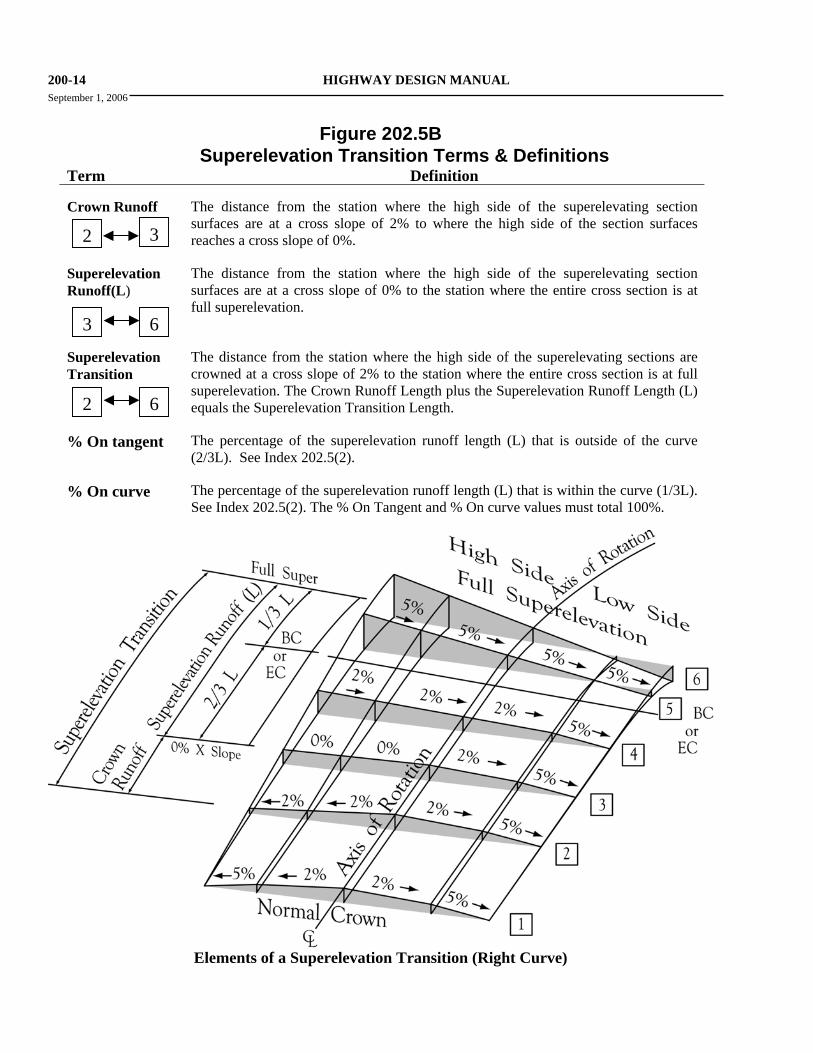
Figure 202.5B Superelevation Transition Terms & Definitions
Term Definition Crown Runoff
The distance from the station where the high side of the superelevating section surfaces are at a cross slope of 2% to where the high side of the section surfaces reaches a cross slope of 0%.
Superelevation Runoff(L)
The distance from the station where the high side of the superelevating section surfaces are at a cross slope of 0% to the station where the entire cross section is at full superelevation.
Superelevation Transition
The distance from the station where the high side of the superelevating sections are crowned at a cross slope of 2% to the station where the entire cross section is at full superelevation. The Crown Runoff Length plus the Superelevation Runoff Length (L) equals the Superelevation Transition Length.
% On tangent The percentage of the superelevation runoff length (L) that is outside of the curve (2/3L). See Index 202.5(2).
% On curve The percentage of the superelevation runoff length (L) that is within the curve (1/3L). See Index 202.5(2). The % On Tangent and % On curve values must total 100%.
32
3 6
2 6
Elements of a Superelevation Transition (Right Curve)
HIGHWAY DESIGN MANUAL 200-29 September 1, 2006
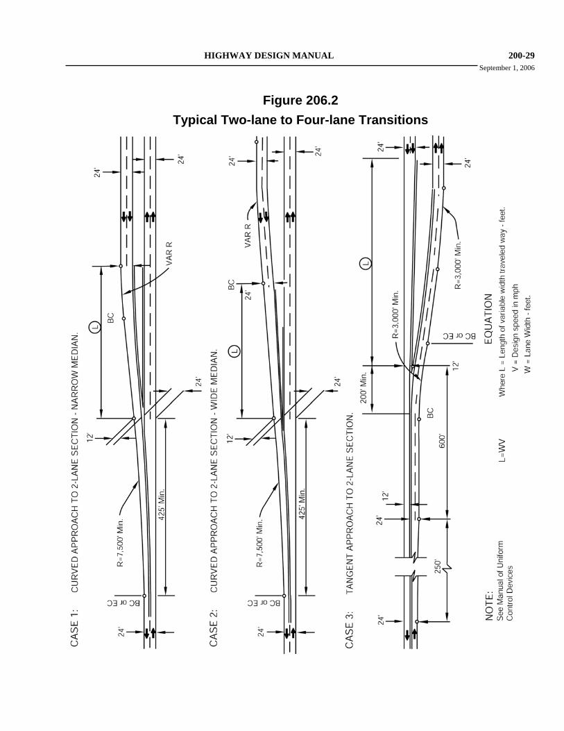
Figure 206.2
Typical Two-lane to Four-lane Transitions
200-30 HIGHWAY DESIGN MANUAL January 4, 2007
(3) Lane Reductions. At any location where lane widths are being reduced, the minimum length over which to accomplish the transition should be equal to WV. See Index 504.6 for mainline lane reductions at interchanges.
(4) Shoulder Reduction. Shoulder reductions should typically occur over a length equal to ¾WV. However, when shoulder widths are being reduced in conjunction with a lane addition or widening (as in Alt. A of Figure 504.3K), the shoulder reduction should be accomplished over the same distance as the addition or widening.
206.4 Temporary Freeway Transitions It is highly desirable that the design standards for a temporary transition between the end of a freeway construction unit and an existing highway should not change abruptly from the freeway standards. Temporary freeway transitions must be reviewed by the Design Coordinator.
Topic 207 - Airway-Highway Clearances
207.1 Introduction (1) Objects Affecting Navigable Airspace. An
object is considered an obstruction to air navigation if any portion of that object is of a height greater than the approach and transverse surfaces extending outward and upward from the airport runway. These objects include overhead signs, light standards, moving vehicles on the highway and overcrossing structures, equipment used during construction, and plants.
(2) Reference. The Federal Aviation Administra-tion (FAA) has published a Federal Aviation Regulation (FAR) relative to airspace clearance entitled, “FAR Part 77, Obstructions Affecting Navigable Airspace”, dated March 1993. This is an approved reference to be used in conjunction with this manual.
207.2 Clearances (a) Civil Airports--See Figure 207.2A.
(b) Heliports--See Figure 207.2B.
(c) Military Airports--See Figure 207.2C.
(d) Navy Carrier Landing Practice Fields--See Figure 207.2D.
207.3 Submittal of Airway-Highway Clearance Data The following procedure must be observed in connection with airway-highway clearances in the vicinity of airports and heliports.
Notice to the FAA is required when highway construction is planned near an airport (civil or military) or a heliport. A "Notice of Proposed Construction or Alteration" should be submitted to the FAA Administrator when required under criteria listed in Paragraph 77.13 of the latest Federal Aviation Regulations, Part 77. Such notice should be given as soon as highway alignment and grade are firmly established. It should be noted that these requirements apply to both permanent objects and construction equipment. When required, four copies of FAA Form 7460-1, “Notice of Proposed Construction”, and accompanying scaled maps must be sent to the FAA, Western-Pacific Regional Office, Chief-Air Traffic Division, AWP-520, 15000 Aviation Boulevard, Hawthorne, CA 90260. Copies of FAA Form 7460-1 may be obtained from the FAA, Western-Pacific Regional Office or Caltrans, Division of Aeronautics.
The scaled maps accompanying FAA Form 7460-1 should contain the following minimum information.
• Distance from project to nearest runway.
• Elevation of runway thresholds.
• Relationship between the proposed highway horizontal alignment and vertical profile to the nearest runway or heliport primary surface. Include elevations of objects referenced to the elevation of the end of the runway, such as overhead lights, signs, structures, landscaping, and vehicles.
HIGHWAY DESIGN MANUAL 200-39 January 4, 2007
(b) Barrier Railing Type 80SW--Similar to the Type 80, modified with a raised sidewalk and tubular handrailing. Use of this barrier requires approval by the HQ Traffic Liaison. It is intended for use in lower speed scenic areas where more see-through area is desired than is provided by a solid concrete parapet.
(c) Chain Link Railing Type 7--This is the fence-type railing for general use with Type 26 barrier railing with sidewalk to reduce the risk of objects being dropped on the roadway below. When a sidewalk (Type 26 railing) is provided on one side of a bridge and Type 732 barrier railing on the other side, Type 7 railing may be placed on top of the Type 732 as additional protection from dropped objects. Consideration should be given to the effect of the Type 7 railing on sight distance at the bridge ends and view over the side of the bridge. Lighting fixtures may be provided with Type 7 railings.
(d) Chain Link Railing Type 6--This railing may be used in lieu of Type 7 when special architectural treatment is required. It should not be used on curved alignment because of fabrication difficulties.
(e) Tubular Handrailing--This railing is used with Type 26 and Type 80SW to increase the combined rail height for the safety of pedestrians. It should be used in lieu of Type 7 where object dropping will not be a problem or at the ends of bridges to increase sight distance if fence-type railing would restrict sight distance.
(5) Pedestrian Railings. See Figure 208.10C
(a) Chain Link Railing Type 3--This railing is used on pedestrian structures to reduce the risk of objects being dropped on the roadway below.
(b) Chain Link Railing Type 7 (Modified)--This railing is similar to Type 7 except that it is mounted on the structure at the sidewalk level.
(c) Chain Link Railing --This railing is not as high as Types 3 or 7 and therefore, its use
is restricted to those locations where object dropping or throwing will not be a problem.
(d) Chain Link Railing (Modification)--Existing railing may be modified for screening under the protective screening policy. The DES-SD should be contacted for details.
(6) Bicycle Railing. The minimum height of bicycle rail is 54 inches above the deck surface. Pedestrian railings and combination railings consisting of a concrete barrier surmounted by a fence or tubular railing are satisfactory for bicycles, if at least 54 inches high. Bicycles are not considered to operate on a sidewalk, except in special cases where signs specifically direct cyclists to use the sidewalk.
As a general policy, bicycle railings should be installed at the following locations:
(a) On a Class I bikeway, except that a lower rail may be used if a curbed sidewalk, not signed for bicycle use, separates the bikeway from the rail or a shoulder at least 8 feet wide exists on the other side of the rail.
(b) On the outside of a Class II or III bikeway, unless a curbed sidewalk, not signed for bicycle use, separates the bikeway from the rail.
(c) In other locations where the designer deems it reasonable and appropriate.
(7) Bridge Approach Railings. Approach railings shall be installed at the ends of bridge railings exposed to approach traffic.
Refer to Chapter 7 of the Traffic Manual for placement and design criteria of guardrail.
208.11 Structure Approach Embankment (1) General. Structure approach embankment is
that portion of the fill material within approximately 150 feet longitudinally of the structure. Refer to Figure 208.11A for limits, the Standard Specifications, and Standard Special Provisions for more information.
200-40 HIGHWAY DESIGN MANUAL September 1, 2006
Quality requirements for embankment material are normally specified only in the case of imported borrow. When select material or local borrow for use in structure abutment embankments is shown on the plans, the Resident Engineer (RE) is responsible for assuring the adequacy of the quantity and quality of the specified material. The Project Engineer should include adequate information and guidance in the RE File to assist the RE in fulfilling this responsibility.
(2) Foundations and Embankment Design. Overall performance of the highway approach to the bridge depends, to a significant degree, upon the long-term settlement/consolidation of the approach foundation and structure abutment embankment. A design that minimizes this post construction settlement/consolidation is essential. Factors that influence settlement/consolidation include soil types and depths, static and dynamic loads, ground water level, adjacent operations, and changes in any of the above. The PE must follow the foundation and embankment recommendations by the Division of Engineering Services, Geotechnical Services (DES-GS) and District Materials Engineer (DME). The DME and/or DES-GS must approve any deviations from their recommendations including Construction Change Orders (CCO’s).
The relative compaction of material within the embankment limits must be at least 95 percent, except for the outer 5 feet of embankment measured horizontally from the side slope (see Figure 208.11A). The DME and/or OSF may recommend using select material, local and/or imported borrow to assure that the compaction requirements are met and that shrink/swell problems are avoided. They may also recommend a height and duration of embankment surcharge to accelerate foundation consolidation.
Poor quality material, such as expansive soils, must be precluded from structure abutment embankments unless treated. If sufficient quality roadway excavation material is unavailable for constructing of structure
abutment embankments, the designer may specify select material, local borrow, or imported borrow to satisfy the design requirements.
(3) Abutment Drainage. Special attention must be given to providing a positive drainage system that minimizes the potential for water damage to the structure approach embankment, see Chapter 870 for further details. The Division of Engineering Services (DES), Structures Design (DES-SD) is responsible for the design of the structure approach drainage system, which includes:
• A geocomposite drain covered with filter fabric placed behind both the abutment wall and wingwalls, as indicated in Figure 208.11B.
• A slotted plastic pipe drain, encapsulated with treated permeable material, placed along the base of the inside face of the abutment wall as illustrated in Figure 208.11B.
(4) Slope Treatment. See Topic 707, Slope Treatment Under Structures, for guidance regarding the treatment of bridge approach end slopes.
The District Hydraulic Engineer or Project Engineer must design a pipe outlet that ties into the structure approach drainage system as it exits the structure. A pipe outlet system should carry the collected water to a location where it will not cause erosion. Storm Water Best Management Practices should be incorporated. For further information on Storm Water Management, visit the Division of Design Storm Water website.
Coordination with DES is necessary for the exit location of the pipe system. The outlet type should be chosen from the standard edge drain outlet types shown in the Standard Plans or tied into an underground drainage system. The PE must review the drainage design to ensure the adequacy of the drainage ties between the structure approach drainage system and either new or existing drainage facilities. For alternative details, see Bridge Design Aids.
HIGHWAY DESIGN MANUAL 200-55 September 1, 2006
appropriate earth retaining system to use can be made.
210.8 Guidelines for Type Selection and Plan Preparation (1) Type Selection. Type selection for reinforced
earth slopes and earth retaining systems should be based on considerations set forth in Index 210.2.
The District PE should request a feasibility study for a reinforced slope or earth retaining system from DES-GS as early as possible in the project development process. After the feasibility study, the District PE should request an Advanced Planning Study (APS) from DES-SD for all special design earth retaining systems that DES-SD may be required to include in the PS&E.
If the District PE decides that the course of action favors an earth retaining system in which the PS&E will be delivered by DES-SD, then a Bridge Site Data Submittal – Non-Standard Retaining Wall/Noise Barrier must be submitted to DES-Structure Design Services & Earthquake Engineering –Preliminary Investgations (PI) Branch. A copy of this submittal will be forwarded to DES-SD and DES-GS by PI.
The Structure PE, with input from DES-GS and the District PE, will then type select the appropriate earth retaining system for the site and project. After an earth retaining system has been type selected, then DES-GS will prepare a Geotechnical Design Report.
The process for type selecting and developing the PS&E for reinforced earth slopes and earth retaining systems is set forth in Figure 210.8.
All appropriate State designed and proprietary earth retaining systems should be considered for inclusion in the contract documents to promote competitive bidding, which can result in cost savings.
(2) Foundation Investigations. DES-GS should be requested to provide a foundation recommendation for all sites involving a reinforced slope or an earth retaining system.
Any log of test boring sheets accompanying the foundation reports must be included with the contract plans as project information, for the bidders use.
(3) Earth Retaining Systems with Standard Plans. The following guidelines should be used to prepare the contract plans for earth retaining systems, which are found in the Standard Plans:
(a) Loads. All wall types selected must be capable of supporting the field surcharge conditions. The design surcharges can be found in the Standard Plans. Deviance from these loadings will require a special design
(b) Footing Steps. For economy and ease of construction of wall Types 1 through 6, the following criteria should be used for layout of footing steps.
• Distance between steps should be in multiples of 8 feet.
• A minimum number of steps should be used even if a slightly higher wall is necessary. Small steps, less than 1 foot in height, should be avoided unless the distance between steps is 96 feet or more. The maximum height of steps should be held to 4 feet. If the footing thickness changes between steps, the bottom of footing elevation should be adjusted so that the top of footing remains at the same elevation.
(c) Sloping Footings. The following criteria should be used for layout of sloping footings.
• The maximum permissible slope for reinforced concrete retaining walls is 3 percent. Maximum footing slope for masonry walls is 2 percent.
• When sloping footings are used, form and joint lines are permitted to be perpendicular and parallel to the footing for ease of construction.
• In cases where vertical electroliers or fence posts are required on top of a
200-56 HIGHWAY DESIGN MANUAL January 4, 2007
wall, the form and joint lines must also be vertical. A sloping footing should not be used in this situation since efficiency of construction would be lost.
Sloping footing grades should be constant for the entire length of the wall. Breaks in footing grade will complicate forming and result in loss of economy. If breaks in footing grade are necessary, a level stepped footing should be used for the entire wall.
• When the top of wall profile of crib walls is constant for the entire length, the bottom of wall profile may be sloped to avoid steps in the top of wall. In this case, all steps to compensate for changes of wall height and original ground profile would be made in the bottom of wall. The maximum permissible slope is 6 percent. If vertical electroliers or fence posts are required on top of the wall, the crib wall should not be sloped. Sloping crib walls are permissible with guard railing with vertical posts.
(d) Wall Joints. General details for required wall joints on wall Types 1, 1A, 2, and 5 are shown on Standard Plan B0-3. Expansion joints, Bridge Detail 3-3, should be shown at maximum intervals of 96 feet. Shorter spaces should be in multiples of 8 feet. Expansion joints generally should be placed near angle points in the wall alignment. When concrete barriers are used on top of retaining walls, the waterstop in the expansion joint must be extended 6 inches into the barrier. This detail should be shown or noted on the wall plans. Weakened plane joints, Bridge Detail 3-2, should be shown at nearly equal spaces between joints.
(e) Drainage. Gutters should be used behind walls in areas where it is necessary to carry off surface water or to prevent scour. Low points in wall vertical
alignment or areas between return walls must be drained by downspouts passing through the walls. Standard Plan B3-9 shows typical drainage details. Special design of surface water drainage facilities may be necessary depending on the amount of surface water anticipated. Where ground water is likely to occur in any quantity, special provisions must be made to intercept the flow to prevent inundation of the backfill and unsightly continuous flow through weep holes.
(f) Quantities. When the AERS procedure is not utilized, quantities for each wall item of work are usually developed for payment. The quantities for concrete, expansion joint waterstop, structure excavation, structure backfill, pervious backfill material, concrete barrier or railing, and gutter concrete must also be tabulated. Quantities should be tabulated on the plans for each wall.
(4) Soil Reinforcement Systems. The following guidelines should be used to prepare the contract plans for soil reinforcement systems:
(a) Leveling Pads. Most soil reinforcement systems do not require extensive foundation preparation. It may be necessary, however, to design a concrete leveling pad on which to construct the face elements. A reinforced concrete leveling pad will be required in areas prone to consolidation or frost disturbance.
• Steps in the leveling pad should be the same height as the height of the facing elements or thickness of the soil layer between the soil reinforcement.
• Distance between steps in the leveling pad should be in increments equivalent to the length of individual facing elements.
• A minimum number of steps should be used even if a slightly higher wall is necessary.
(b) Drainage. Gutters should be used behind walls in areas where it is necessary to carry off surface water or to prevent
HIGHWAY DESIGN MANUAL 300-1 September 1, 2006
CHAPTER 300 GEOMETRIC CROSS SECTION
Topic 301 - Traveled Way Standards
Index 301.1 - Traveled Way Width The traveled way width is determined by the number of lanes demanded by the design hourly volume. The traveled way width does not include curbs, dikes, gutters, or gutter pans. The basic lane width for new construction on two-lane and multilane highways, ramps, collector roads, and other appurtenant roadways shall be 12 feet. For roads with curve radii of 300 feet or less, widening due to offtracking should be considered. See Index 404.1 and Table 504.3A. For roads under other jurisdictions, see Topic 308.
301.2 Cross Slopes (1) General. The purpose of sloping on roadway
cross sections is to provide a mechanism to direct water (usually from precipitation) off the traveled way. Undesirable accumulations of water can lead to hydroplaning or other problems which can increase accident potential. See Topics 831 and 833 for hydroplaning considerations.
(2) Standards.
(a) The standard cross slope to be used for new construction on the traveled way for all types of surfaces shall be 2 percent.
(b) For resurfacing or widening when necessary to match existing cross slopes, the minimum shall be 1.5 percent and the maximum shall be 3 percent. However, the cross slope on 2-lane and multilane AC highways should be increased to 2 percent if the cost is reasonable.
(c) On unpaved roadway surfaces, including gravel and penetration treated earth, the cross slope shall be 2.5 percent to 5.0 percent.
On undivided highways with two or more lanes in a normal tangent section, the high point of the crown should be centered on the pavement and the pavement sloped toward the edges on a uniform grade.
For rehabilitation and widening projects, the maximum algebraic difference in cross slope between adjacent lanes of opposing traffic for either 2-lane or undivided multilane highways should be 6 percent. For new construction, the maximum shall be 4 percent.
On divided highway roadbeds, the high point of crown may be centered at, or left of, the center of the traveled way, and preferably over a lane line (tent sections). This strategy may be employed when adding lanes on the inside of divided highways, or when widening an existing "crowned" 2-lane highway to a 4-lane divided highway by utilizing the existing 2-lane pavement as one of the divided highway roadbeds.
The maximum algebraic difference in cross slope between same direction traffic lanes of divided highway roadbeds should be 4 percent.
The maximum difference in cross slope between the traveled way and the shoulder should not exceed 8 percent. This applies to new construction as well as pavement overlay projects.
At freeway entrances and exits, the maximum difference in cross slope between adjacent lanes, or between lanes and gore areas, should not exceed 5 percent.
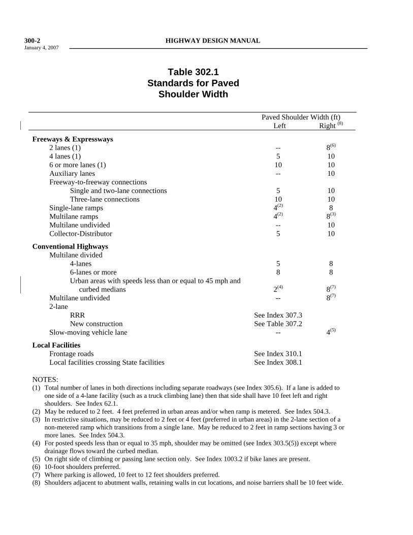
Topic 302 - Shoulder Standards 302.1 Width The shoulder widths given in Table 302.1 shall be the minimum continuous usable width of paved shoulder. For new construction, and major reconstruction projects on conventional highways, adequate width should be provided to permit shared use by motorists and bicyclists.
See Index 308.1 for shoulder width requirements on city streets or county roads. See shoulder definition, Index 62.1(7).
See Index 1102.2 for shoulder width requirements next to noise Barriers.
300-2 HIGHWAY DESIGN MANUAL January 4, 2007
Table 302.1 Standards for Paved
Shoulder Width Paved Shoulder Width (ft) Left Right (8)
Freeways & Expressways
2 lanes (1) -- 8(6)
4 lanes (1) 5 10 6 or more lanes (1) 10 10 Auxiliary lanes -- 10 Freeway-to-freeway connections Single and two-lane connections 5 10 Three-lane connections 10 10 Single-lane ramps 4(2) 8 Multilane ramps 4(2) 8(3)
Multilane undivided -- 10 Collector-Distributor 5 10
Conventional Highways
Multilane divided 4-lanes 5 8 6-lanes or more 8 8 Urban areas with speeds less than or equal to 45 mph and
curbed medians
2(4)
8(7)
Multilane undivided -- 8(7)
2-lane RRR See Index 307.3 New construction See Table 307.2 Slow-moving vehicle lane -- 4(5)
Local Facilities
Frontage roads See Index 310.1 Local facilities crossing State facilities See Index 308.1 NOTES: (1) Total number of lanes in both directions including separate roadways (see Index 305.6). If a lane is added to
one side of a 4-lane facility (such as a truck climbing lane) then that side shall have 10 feet left and right shoulders. See Index 62.1.
(2) May be reduced to 2 feet. 4 feet preferred in urban areas and/or when ramp is metered. See Index 504.3. (3) In restrictive situations, may be reduced to 2 feet or 4 feet (preferred in urban areas) in the 2-lane section of a
non-metered ramp which transitions from a single lane. May be reduced to 2 feet in ramp sections having 3 or more lanes. See Index 504.3.
(4) For posted speeds less than or equal to 35 mph, shoulder may be omitted (see Index 303.5(5)) except where drainage flows toward the curbed median.
(5) On right side of climbing or passing lane section only. See Index 1003.2 if bike lanes are present. (6) 10-foot shoulders preferred. (7) Where parking is allowed, 10 feet to 12 feet shoulders preferred. (8) Shoulders adjacent to abutment walls, retaining walls in cut locations, and noise barriers shall be 10 feet wide.
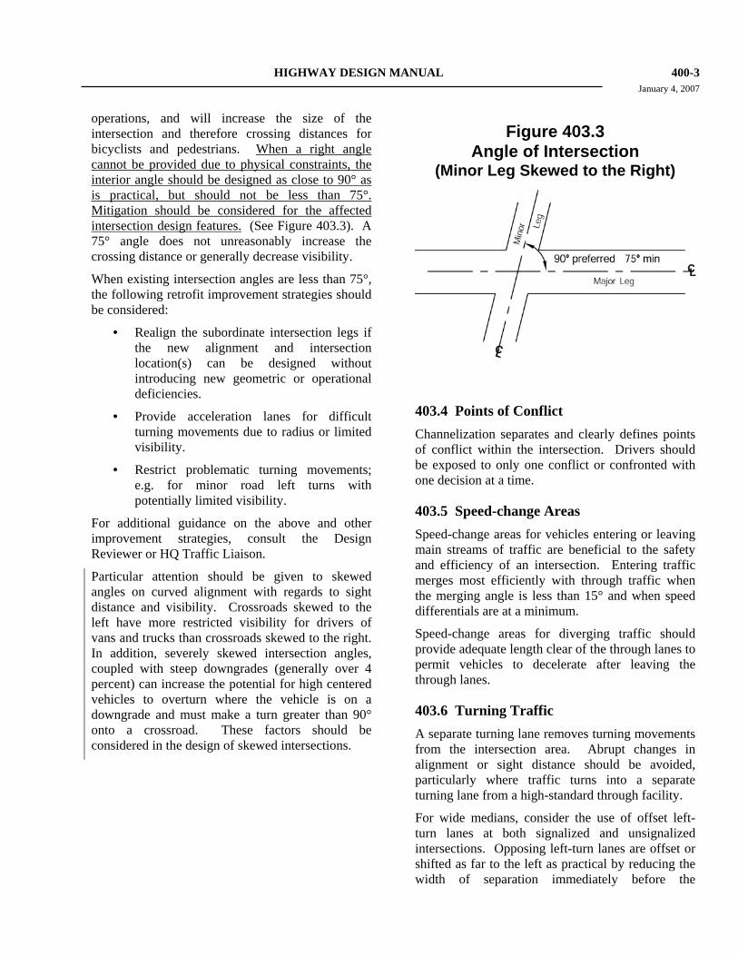
HIGHWAY DESIGN MANUAL 400-3 January 4, 2007 operations, and will increase the size of the intersection and therefore crossing distances for bicyclists and pedestrians. When a right angle cannot be provided due to physical constraints, the interior angle should be designed as close to 90° as is practical, but should not be less than 75°. Mitigation should be considered for the affected intersection design features. (See Figure 403.3). A 75° angle does not unreasonably increase the crossing distance or generally decrease visibility.
When existing intersection angles are less than 75°, the following retrofit improvement strategies should be considered:
• Realign the subordinate intersection legs if the new alignment and intersection location(s) can be designed without introducing new geometric or operational deficiencies.
• Provide acceleration lanes for difficult turning movements due to radius or limited visibility.
• Restrict problematic turning movements; e.g. for minor road left turns with potentially limited visibility.
For additional guidance on the above and other improvement strategies, consult the Design Reviewer or HQ Traffic Liaison.
Particular attention should be given to skewed angles on curved alignment with regards to sight distance and visibility. Crossroads skewed to the left have more restricted visibility for drivers of vans and trucks than crossroads skewed to the right. In addition, severely skewed intersection angles, coupled with steep downgrades (generally over 4 percent) can increase the potential for high centered vehicles to overturn where the vehicle is on a downgrade and must make a turn greater than 90° onto a crossroad. These factors should be considered in the design of skewed intersections.
Figure 403.3 Angle of Intersection
(Minor Leg Skewed to the Right)
403.4 Points of Conflict Channelization separates and clearly defines points of conflict within the intersection. Drivers should be exposed to only one conflict or confronted with one decision at a time.
403.5 Speed-change Areas Speed-change areas for vehicles entering or leaving main streams of traffic are beneficial to the safety and efficiency of an intersection. Entering traffic merges most efficiently with through traffic when the merging angle is less than 15° and when speed differentials are at a minimum.
Speed-change areas for diverging traffic should provide adequate length clear of the through lanes to permit vehicles to decelerate after leaving the through lanes.
403.6 Turning Traffic A separate turning lane removes turning movements from the intersection area. Abrupt changes in alignment or sight distance should be avoided, particularly where traffic turns into a separate turning lane from a high-standard through facility.
For wide medians, consider the use of offset left-turn lanes at both signalized and unsignalized intersections. Opposing left-turn lanes are offset or shifted as far to the left as practical by reducing the width of separation immediately before the
400-4 HIGHWAY DESIGN MANUAL September 1, 2006 intersection. Rather than aligning the left-turn lane exactly parallel with and adjacent to the through lane, the offset left-turn lane is separated from the adjacent through lane. Offset left-turn lanes provide improved visibility of opposing through traffic. For further guidance on offset left-turn lanes, see AASHTO, A Policy on Geometric Design of Highways and Streets.
403.7 Refuge Areas The shadowing effect of traffic islands may be used to provide refuge areas for turning and crossing vehicles. Adequate shadowing provides refuge for a vehicle waiting to cross or enter an uncontrolled traffic stream. Similarly, channelization also may provide a safer crossing of two or more traffic streams by permitting drivers to select a time gap in one traffic stream at a time.
Traffic islands also may serve the same purposes for pedestrians and disabled persons.
403.8 Prohibited Turns Traffic islands may be used to divert traffic streams in desired directions and prevent undesirable movements. Care should be taken that islands used for this purpose accommodate convenient and safe pedestrian crossings, drainage, and striping options. See Topic 303.
403.9 Effective Signal Control At intersections with complex turning movements, channelization is required for effective signal control. Channelization permits the sorting of approaching traffic which may move through the intersection during separate signal phases. This requirement is of particular importance when traffic-actuated signal controls are employed.
403.10 Installation of Traffic Control Devices Channelization may provide locations for the installation of essential traffic control devices, such as stop and directional signs. See Index 405.4 for information about the design of traffic islands.
403.11 Summary • Give preference to the major move(s). • Reduce areas of conflict. • Cross traffic at right angles or skew no more
than 75 degrees. (90 degrees preferred.) • Separate points of conflict. • Provide speed-change areas and separate
turning lanes where appropriate. • Provide adequate width to shadow turning
traffic.
• Restrict undesirable moves with traffic islands.
• Coordinate channelization with effective signal control.
• Install signs in traffic islands when neces-sary, but avoid built-in hazards.
403.12 Precautions • Striping is usually preferable to curbed is-
lands, especially adjacent to high-speed traffic where curbing can be an obstruction to out-of-control vehicles.
• Where curbing must be used, first consid-eration should be given to mountable curbs. Barrier curbs are usually justified only where protection of pedestrians is a primary consideration.
• Avoid complex intersections that present multiple choices of movement to the driver.
• Traffic safety should be considered. Accident records provide a valuable guide to the type of channelization needed.
Topic 404 - Design Vehicles
404.1 Offtracking Any vehicle whether car, bus, truck, or combination tractor semi-trailer while turning a curve covers a wider path than the width of the vehicle. The front steering axle can generally follow a circular curve, but the following axles (and trailers) will swing inside toward the center of the curve. Some terminology is vital to understanding the engineering concepts. Tracking width is the
HIGHWAY DESIGN MANUAL 400-7 January 4, 2007
404.3 Turning Templates (1) General. The truck-turn template is a design
aid for locating the wheel paths of large vehicles as they turn through at-grade intersections. Consideration should be given to the overhang of the truck, where the body of the truck slightly extends (approximately 2 feet) beyond the wheel path. The template is useful for determining corner radii, for positioning island noses, and for establishing clearance to bridge piers, signal poles, and other hardware at intersections. Templates can help determine the width of a channeled separate turning lane. Topic 407 illustrates scaled turning templates for the various design vehicles and turning radii.
(2) STAA Truck. The STAA truck-turn templates should be used in the design of all new interchanges and intersections on the National Network and on routes leading from the National Network to designated service and terminal routes. On rehabilitation projects they should be used at interchanges and intersections proposed as service or terminal access routes. In some cases, factors such as cost, right of way, environmental issues, local agency desires, and the type of community being served may limit the use of the STAA templates. In those cases, other appropriate templates should be used.
The minimum practical turning radius is 50 feet. However, the 60-foot radius develops less swept width and may have an advantage. The 60-foot radius should be used in most situations, but the 50-foot radius is acceptable in restricted situations.
(3) California Truck. The California truck-turn template should be used in the design of highways not on the National Network. The minimum practical turning radius is 50 feet.
(4) Bus. At intersections where truck volumes are light or where the predominate truck traffic consists of mostly 3-axle and 4-axle units, the bus turning template may be used. Its wheel paths sweep a greater width than 3-axle delivery trucks and the smaller buses such as
school buses, but a slightly lesser width than a 4-axle truck.
Topic 405 - Intersection Design Standards
405.1 Sight Distance (1) Stopping Sight Distance. See Index 201.1 for
minimum stopping sight distance requirements.
(2) Corner Sight Distance.
(a) General--At unsignalized intersections a substantially clear line of sight should be maintained between the driver of a vehicle waiting at the crossroad and the driver of an approaching vehicle.
Adequate time must be provided for the waiting vehicle to either cross all lanes of through traffic, cross the near lanes and turn left, or turn right, without requiring through traffic to radically alter their speed.
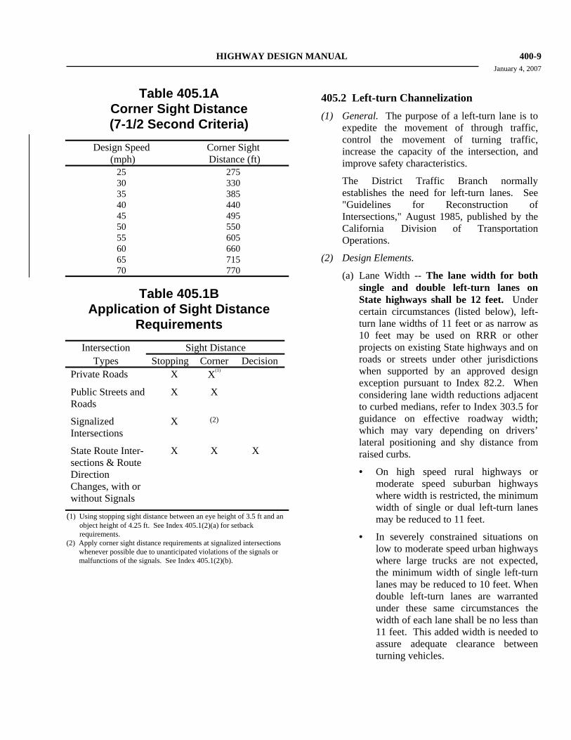
The values given in Table 405.1A provide 7-1/2 seconds for the driver on the crossroad to complete the necessary maneuver while the approaching vehicle travels at the assumed design speed of the main highway. The 7-1/2 second criterion is normally applied to all lanes of through traffic in order to cover all possible maneuvers by the vehicle at the crossroad. However, by providing the standard corner sight distance to the lane nearest to and farthest from the waiting vehicle, adequate time should be obtained to make the necessary movement. On multilane highways a 7-1/2 second criterion for the outside lane, in both directions of travel, normally will provide increased sight distance to the inside lanes. Consideration should be given to increasing these values on downgrades steeper than 3 percent and longer than 1 mile (see Index 201.3), where there are high truck volumes on the crossroad, or where the skew of the intersection substantially increases the distance traveled by the crossing vehicle.
400-8 HIGHWAY DESIGN MANUAL January 4, 2007 In determining corner sight distance, a set
back distance for the vehicle waiting at the crossroad must be assumed. Set back for the driver on the crossroad shall be a minimum of 10 feet plus the shoulder width of the major road but not less than 13 feet. Corner sight distance is to be measured from a 3.5-foot height at the location of the driver on the minor road to a 4.25-foot object height in the center of the approaching lane of the major road. If the major road has a median barrier, a 2-foot object height should be used to determine the median barrier set back.
In some cases the cost to obtain 7-1/2 seconds of corner sight distances may be excessive. High costs may be attributable to right of way acquisition, building removal, extensive excavation, or unmitigable environmental impacts. In such cases a lesser value of corner sight distance, as described under the following headings, may be used.
(b) Public Road Intersections (Refer to Topic 205)--At unsignalized public road intersections (see Index 405.7) corner sight distance values given in Table 405.1A should be provided.
At signalized intersections the values for corner sight distances given in Table 405.1A should also be applied whenever possible. Even though traffic flows are designed to move at separate times, unanticipated vehicle conflicts can occur due to violation of signal, right turns on red, malfunction of the signal, or use of flashing red/yellow mode.
Where restrictive conditions exist, similar to those listed in Index 405.1(2)(a), the minimum value for corner sight distance at both signalized and unsignalized intersections shall be equal to the stopping sight distance as given in Table 201.1, measured as previously described.
(c) Private Road Intersections (Refer to Index 205.2) and Rural Driveways (Refer to Index 205.4)--The minimum corner sight
distance shall be equal to the stopping sight distance as given in Table 201.1, measured as previously described.
(d) Urban Driveways (Refer to Index 205.3)--Corner sight distance requirements as described above are not applied to urban driveways.
(3) Decision Sight Distance. At intersections where the State route turns or crosses another State route, the decision sight distance values given in Table 201.7 should be used. In computing and measuring decision sight distance, the 3.5-foot eye height and the 0.5-foot object height should be used, the object being located on the side of the intersection nearest the approaching driver.
The application of the various sight distance requirements for the different types of intersections is summarized in Table 405.1B.
(4) Acceleration Lanes for Turning Moves onto State Highways. At rural intersections, with stop control on the local cross road, acceleration lanes for left and right turns onto the State facility should be considered. At a minimum, the following features should be evaluated for both the major highway and the cross road:
• divided versus undivided
• number of lanes
• design speed
• gradient
• lane, shoulder and median width
• traffic volume and composition
• turning volumes
• horizontal curve radii
• sight distance
• proximity of adjacent intersections
• types of adjacent intersections
For additional information and guidance, refer to AASHTO, A Policy on Geometric Design of Highways and Streets, the Headquarters Traffic Liaison and the Design Coordinator.
HIGHWAY DESIGN MANUAL 400-9 January 4, 2007
Table 405.1A Corner Sight Distance (7-1/2 Second Criteria)
Design Speed (mph)
Corner Sight Distance (ft)
25 275 30 330 35 385 40 440 45 495 50 550 55 605 60 660 65 715 70 770
Table 405.1B Application of Sight Distance
Requirements Intersection Sight Distance
Types Stopping Corner Decision
Private Roads X X(1)
Public Streets and Roads X X
Signalized Intersections
X (2)
State Route Inter-sections & Route Direction Changes, with or without Signals
X X X
(1) Using stopping sight distance between an eye height of 3.5 ft and an object height of 4.25 ft. See Index 405.1(2)(a) for setback requirements.
(2) Apply corner sight distance requirements at signalized intersections whenever possible due to unanticipated violations of the signals or malfunctions of the signals. See Index 405.1(2)(b).
405.2 Left-turn Channelization (1) General. The purpose of a left-turn lane is to
expedite the movement of through traffic, control the movement of turning traffic, increase the capacity of the intersection, and improve safety characteristics.
The District Traffic Branch normally establishes the need for left-turn lanes. See "Guidelines for Reconstruction of Intersections," August 1985, published by the California Division of Transportation Operations.
(2) Design Elements.
(a) Lane Width -- The lane width for both single and double left-turn lanes on State highways shall be 12 feet. Under certain circumstances (listed below), left-turn lane widths of 11 feet or as narrow as 10 feet may be used on RRR or other projects on existing State highways and on roads or streets under other jurisdictions when supported by an approved design exception pursuant to Index 82.2. When considering lane width reductions adjacent to curbed medians, refer to Index 303.5 for guidance on effective roadway width; which may vary depending on drivers’ lateral positioning and shy distance from raised curbs.
• On high speed rural highways or moderate speed suburban highways where width is restricted, the minimum width of single or dual left-turn lanes may be reduced to 11 feet.
• In severely constrained situations on low to moderate speed urban highways where large trucks are not expected, the minimum width of single left-turn lanes may be reduced to 10 feet. When double left-turn lanes are warranted under these same circumstances the width of each lane shall be no less than 11 feet. This added width is needed to assure adequate clearance between turning vehicles.
400-10 HIGHWAY DESIGN MANUAL September 1, 2006
(b) Approach Taper -- On a conventional highway without a median, an approach taper provides space for a left-turn lane by moving traffic laterally to the right. The approach taper is unnecessary where a median is available for the full width of the left-turn lane. Length of the approach taper is given by the formula on Figures 405.2A, B and C.
Figure 405.2A shows a standard left-turn channelization design in which all widening is to the right of approaching traffic and the deceleration lane (see below) begins at the end of the approach taper. This design should be used in all situations where space is available, usually in rural and semi-rural areas or in urban areas with high traffic speeds and/or volumes.
Figures 405.2B and 405.2C show alternate designs foreshortened with the deceleration lane beginning at the 2/3 point of the approach taper so that part of the deceleration takes place in the through traffic lane. Figure 405.2C is shortened further by widening half (or other appropriate fraction) on each side. These designs may be used in urban areas where constraints exist, speeds are moderate and traffic volumes are relatively low.
(c) Bay Taper -- A reversing curve along the left edge of the traveled way directs traffic into the left-turn lane. The length of this bay taper should be short to clearly delin-eate the left-turn move and to discourage through traffic from drifting into the left-turn lane. Table 405.2A gives offset data for design of bay tapers. In urban areas, lengths of 60 feet and 90 feet are normally used. Where space is restricted and speeds are low, a 60-foot bay taper is appropriate. On rural high-speed highways, a 120-foot length is considered appropriate.
(d) Deceleration Lane Length -- Design speed of the roadway approaching the intersection should be the basis for determining deceleration lane length. It is desirable that deceleration take place
entirely off the through traffic lanes. Deceleration lane lengths are given in Table 405.2B; the bay taper length is in-cluded. Where partial deceleration is permitted on the through lanes, as in Figures 405.2B and 405.2C, design speeds in Table 405.2B may be reduced 10 mph to 20 mph for a lower entry speed. In urban areas where cross streets are closely spaced and deceleration lengths cannot be achieved, the District Traffic branch should be consulted for guidance.
Table 405.2A
Bay Taper for Median Speed-change Lanes
NOTES:
(1)
The table gives offsets from a base line parallel to the edge of traveled way at intervals measured from point "A". Add "E" for measurements from edge of traveled way.
(2)
Where edge of traveled way is a curve, neither base line nor taper between B & C will be a tangent. Use proportional offsets from B to C.
(3) The offset "E" is usually 2 ft along edge of traveled way for curbed medians; Use "E" = 0 ft. for striped medians.
HIGHWAY DESIGN MANUAL 400-17 September 1, 2006
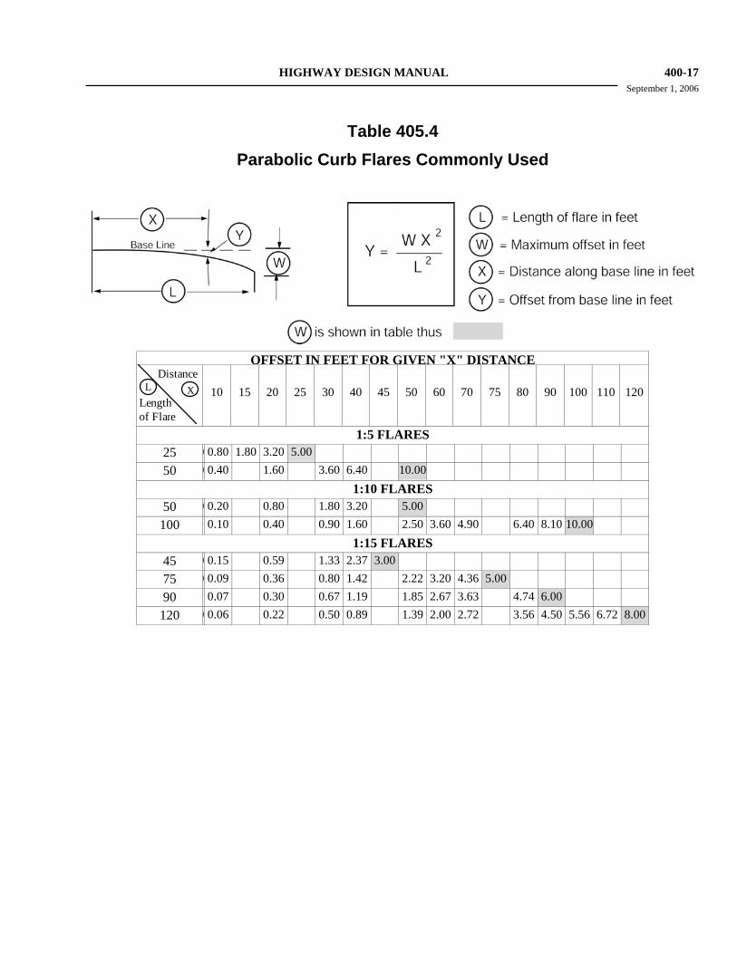
Table 405.4
Parabolic Curb Flares Commonly Used
OFFSET IN FEET FOR GIVEN "X" DISTANCE
Distance
Lengthof Flare
L X
10 15 20 25 30 40 45 50 60 70 75 80 90 100 110 120
1:5 FLARES 25 00.80 1.80 3.20 5.00 50 00.40 1.60 3.60 6.40 10.00
1:10 FLARES 50 00.20 0.80 1.80 3.20 5.00
100 0.10 0.40 0.90 1.60 2.50 3.60 4.90 6.40 8.10 10.00 1:15 FLARES
45 00.15 0.59 1.33 2.37 3.00 75 00.09 0.36 0.80 1.42 2.22 3.20 4.36 5.00 90 0.07 0.30 0.67 1.19 1.85 2.67 3.63 4.74 6.00
120 00.06 0.22 0.50 0.89 1.39 2.00 2.72 3.56 4.50 5.56 6.72 8.00
400-18 HIGHWAY DESIGN MANUAL January 4, 2007 In urban areas, speeds less than 45 miles per
hour allow more frequent use of curbed islands. Local agency requirements and matching existing conditions are factors to consider.
405.5 Median Openings (1) General. Median openings, sometimes called
crossovers, provide for vehicular crossings of the median at designated locations. Except for emergency passageways in a median barrier, median openings are not allowed on urban freeways.
Median openings on expressways or divided conventional highways should not be curbed except when the median between openings is curbed, or it is necessary for delineation or for protection of traffic signal standards and other necessary hardware. In these special cases B4 curbs should be used. An example of a median opening design is shown on Figure 405.5.
(2) Spacing and Location. By a combination of interchange ramps and emergency passageways, provisions for access to the opposite side of the freeway may be provided for law enforcement, emergency, and maintenance vehicles to avoid extreme out-of-direction travel. Access should not be more frequent than at three-mile intervals. See Chapter 7 of the Traffic Manual for additional information on the design of emergency pas-sageways. Emergency passageways should be located where decision sight distance is avail-able (see Table 201.7).
Median openings at close intervals on other types of highways create interference with fast through traffic. Median openings should be spaced at intervals no closer than 1600 feet. If a median opening falls within 300 feet of an access opening, it should be placed opposite the access opening.
(3) Length of Median Opening. For any three or four-leg intersection on a divided highway, the length of the median opening should be at least as great as the width of the crossroads pavement, median width, and shoulders. An important factor in designing median openings
is the path of the design vehicle making a minimum left turn at 5 mph to 10 mph. The length of median opening varies with width of median and angle of intersecting road.
Usually a median opening of 60 feet is adequate for 90° intersections with median widths of 22 feet or greater. When the median width is less than 22 feet, a median opening of 70 feet is needed. When the intersection angle is other than 90°, the length of median opening should be established by using truck turn templates (see Index 404.3).
(4) Cross Slope. The cross slope in the median opening should be limited to 5 percent. Crossovers on curves with super elevation ex-ceeding 5 percent should be avoided. This cross slope may be exceeded when an existing 2-lane roadbed is converted to a 4-lane divided highway. The elevation of the new construction should be based on the 5 percent cross slope requirement when the existing roadbed is raised to its ultimate elevation.
(5) References. For information related to the design of intersections and median openings, "A Policy on Geometric Design of Highways and Streets," AASHTO, should be consulted.
405.6 Access Control The basic principles which govern the extent to which access rights are to be acquired at interchanges (see Index 205.1 and 504.8) also apply to intersections at grade on expressways. Cases of access control which frequently occur at intersections are shown in Figure 405.7. This illustration does not presume to cover all situations. Where required by traffic conditions, access taking should be extended in order to ensure proper operation of the expressway lanes. Reasonable variations which observe the basic principles referred to above are acceptable.
HIGHWAY DESIGN MANUAL 500-9 September 1, 2006
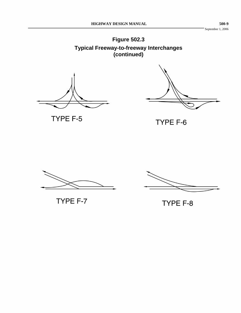
Figure 502.3
Typical Freeway-to-freeway Interchanges (continued)
500-10 HIGHWAY DESIGN MANUAL January 4, 2007
(a) The location and standards of existing and proposed local streets including types of traffic control.
(b) Existing and proposed land use including such developments as shopping centers, recreational facilities, housing developments, schools, and other institutions.
(c) A traffic flow diagram showing average daily traffic and design hourly volumes, as well as time of day (a.m. or p.m.), anticipated on the freeway ramps and affected local streets or roads.
(d) The relationship with adjacent interchanges.
(e) The location of major utilities, railroads, or airports.
503.2 Reviews Interchanges are among the major design features which are to be reviewed by the Design Coordinator and/or Design Reviewer, HQ Traffic Liaison, other Headquarters staff, and the FHWA Field Operations Engineer, as appropriate. Major design features include the freeway alignment, geometric cross section, location of separation structures, closing of local roads, frontage road construction, and work on local roads. Particularly close involvement should occur during preparation of the Project Study Report and Project Report (see the Project Development Procedures Manual). Such reviews can be particularly valuable when exceptions from advisory or mandatory design standards are being considered and alternatives are being sought.
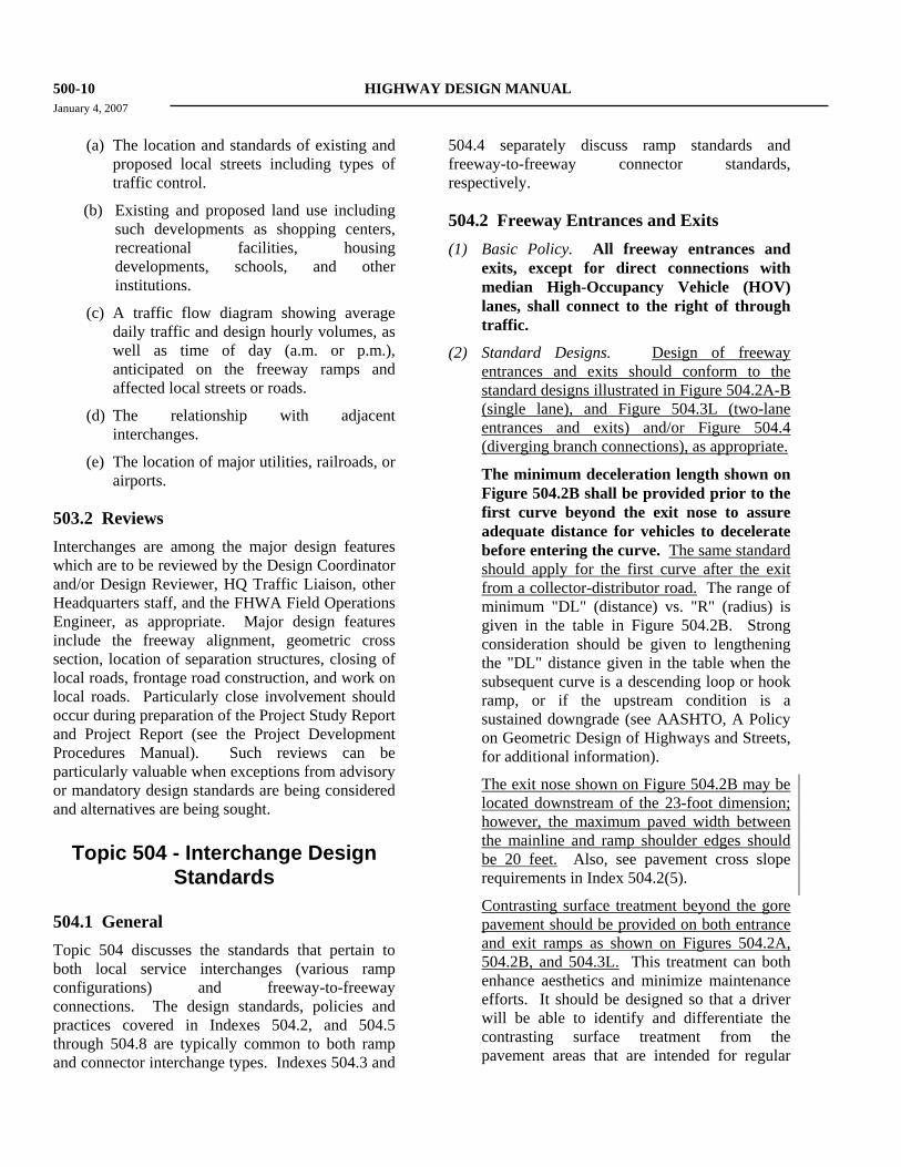
Topic 504 - Interchange Design Standards
504.1 General Topic 504 discusses the standards that pertain to both local service interchanges (various ramp configurations) and freeway-to-freeway connections. The design standards, policies and practices covered in Indexes 504.2, and 504.5 through 504.8 are typically common to both ramp and connector interchange types. Indexes 504.3 and
504.4 separately discuss ramp standards and freeway-to-freeway connector standards, respectively.
504.2 Freeway Entrances and Exits (1) Basic Policy. All freeway entrances and
exits, except for direct connections with median High-Occupancy Vehicle (HOV) lanes, shall connect to the right of through traffic.
(2) Standard Designs. Design of freeway entrances and exits should conform to the standard designs illustrated in Figure 504.2A-B (single lane), and Figure 504.3L (two-lane entrances and exits) and/or Figure 504.4 (diverging branch connections), as appropriate.
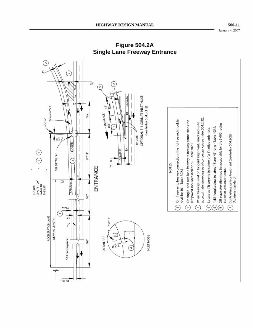
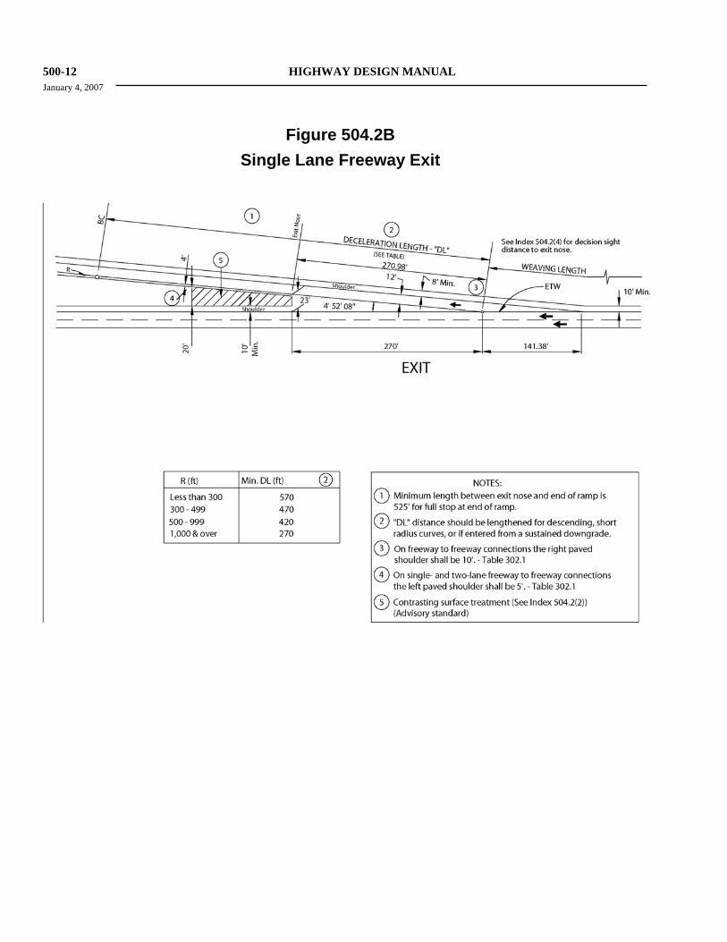
The minimum deceleration length shown on Figure 504.2B shall be provided prior to the first curve beyond the exit nose to assure adequate distance for vehicles to decelerate before entering the curve. The same standard should apply for the first curve after the exit from a collector-distributor road. The range of minimum "DL" (distance) vs. "R" (radius) is given in the table in Figure 504.2B. Strong consideration should be given to lengthening the "DL" distance given in the table when the subsequent curve is a descending loop or hook ramp, or if the upstream condition is a sustained downgrade (see AASHTO, A Policy on Geometric Design of Highways and Streets, for additional information).
The exit nose shown on Figure 504.2B may be located downstream of the 23-foot dimension; however, the maximum paved width between the mainline and ramp shoulder edges should be 20 feet. Also, see pavement cross slope requirements in Index 504.2(5).
Contrasting surface treatment beyond the gore pavement should be provided on both entrance and exit ramps as shown on Figures 504.2A, 504.2B, and 504.3L. This treatment can both enhance aesthetics and minimize maintenance efforts. It should be designed so that a driver will be able to identify and differentiate the contrasting surface treatment from the pavement areas that are intended for regular
HIGHWAY DESIGN MANUAL 500-11 January 4, 2007
Figure 504.2A Single Lane Freeway Entrance
500-12 HIGHWAY DESIGN MANUAL January 4, 2007
Figure 504.2B
Single Lane Freeway Exit
HIGHWAY DESIGN MANUAL 500-13 September 1, 2006
or occasional vehicular use (e.g., traveled way, shoulders, paved gore, etc.).
Consult with the District Landscape Architect, District Materials Engineer, and District Maintenance Engineer to determine the appropriate contrasting surface treatment of the facility at a specific location.
Refer to the HOV Guidelines for additional information specific to direct connections to HOV lanes.
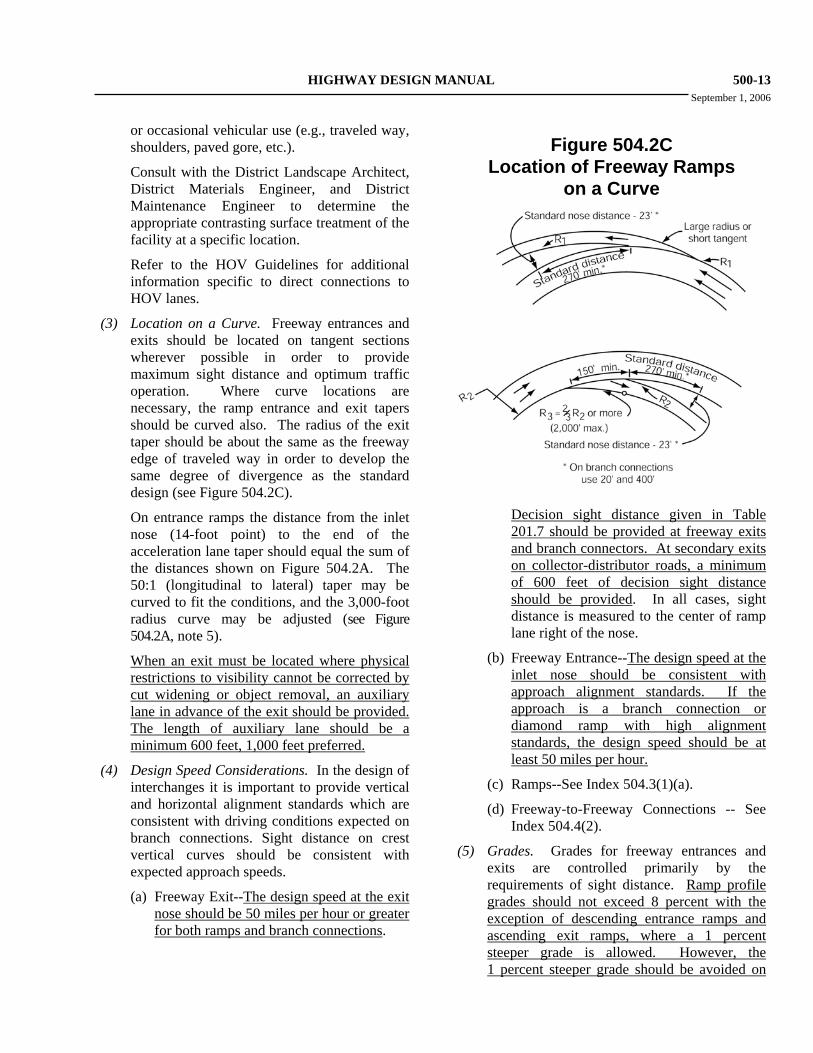
(3) Location on a Curve. Freeway entrances and exits should be located on tangent sections wherever possible in order to provide maximum sight distance and optimum traffic operation. Where curve locations are necessary, the ramp entrance and exit tapers should be curved also. The radius of the exit taper should be about the same as the freeway edge of traveled way in order to develop the same degree of divergence as the standard design (see Figure 504.2C).
On entrance ramps the distance from the inlet nose (14-foot point) to the end of the acceleration lane taper should equal the sum of the distances shown on Figure 504.2A. The 50:1 (longitudinal to lateral) taper may be curved to fit the conditions, and the 3,000-foot radius curve may be adjusted (see Figure 504.2A, note 5).
When an exit must be located where physical restrictions to visibility cannot be corrected by cut widening or object removal, an auxiliary lane in advance of the exit should be provided. The length of auxiliary lane should be a minimum 600 feet, 1,000 feet preferred.
(4) Design Speed Considerations. In the design of interchanges it is important to provide vertical and horizontal alignment standards which are consistent with driving conditions expected on branch connections. Sight distance on crest vertical curves should be consistent with expected approach speeds.
(a) Freeway Exit--The design speed at the exit nose should be 50 miles per hour or greater for both ramps and branch connections.
Figure 504.2C Location of Freeway Ramps
on a Curve
Decision sight distance given in Table
201.7 should be provided at freeway exits and branch connectors. At secondary exits on collector-distributor roads, a minimum of 600 feet of decision sight distance should be provided. In all cases, sight distance is measured to the center of ramp lane right of the nose.
(b) Freeway Entrance--The design speed at the inlet nose should be consistent with approach alignment standards. If the approach is a branch connection or diamond ramp with high alignment standards, the design speed should be at least 50 miles per hour.
(c) Ramps--See Index 504.3(1)(a).
(d) Freeway-to-Freeway Connections -- See Index 504.4(2).
(5) Grades. Grades for freeway entrances and exits are controlled primarily by the requirements of sight distance. Ramp profile grades should not exceed 8 percent with the exception of descending entrance ramps and ascending exit ramps, where a 1 percent steeper grade is allowed. However, the 1 percent steeper grade should be avoided on
500-14 HIGHWAY DESIGN MANUAL January 4, 2007
descending loops to minimize overdriving of the ramp (see Index 504.3 (8)).
Profile grade considerations are of particular concern through entrance and exit gore areas. In some instances the profile of the ramp or connector, or a combination of profile and cross slope, is sufficiently different than that of the freeway through lanes that grade breaks across the gore may become necessary. Where adjacent lanes or lanes and paved gore areas at freeway entrances and exits are not in the same plane, the algebraic difference in pavement cross slope should not exceed 5 percent (see Index 301.2). The paved gore area is typically that area between the diverging or converging edge of traveled ways and the 23-foot point.
In addition to the effects of terrain, grade lines are also controlled by structure clearances (see Indexes 204.6 and 309.2). Grade lines for overcrossing and undercrossing roadways should conform to the requirements of HDM Topic 104 Roads Under Other Jurisdictions.
(a) Freeway Exits--Vertical curves located just beyond the exit nose should be designed with a minimum 50 miles per hour stopping sight distance. Beyond this point, progressively lower design speeds may be used to accommodate loop ramps and other geometric features.
Ascending off-ramps should join the crossroads on a reasonably flat grade to expedite truck starts from a stopped condition. If the ramp ends in a crest vertical curve, the last 50 feet of the ramp should be on a 5 percent grade or less. There may be cases where a drainage feature is necessary to prevent crossroads water from draining onto the ramp.
On descending off-ramps, the sag vertical curve at the ramp terminal should be a minimum of 100 feet in length.
(b) Freeway Entrances--Entrance profiles should approximately parallel the profile of the freeway for at least 100 feet prior to the inlet nose to provide intervisibility in merging situations. The vertical curve at
the inlet nose should be consistent with approach alignment standards.
Where truck volumes (three-axle or more) exceed 20 per hour on ascending entrance ramps to freeways and expressways with sustained upgrades exceeding 2 percent, a 1,500-foot length of auxiliary lane should be provided in order to insure satisfactory operating conditions. Additional length may be warranted based on the thorough analysis of the site specific grades, traffic volumes, and calculated speeds; and after consultation with representatives of the Headquarters Division of Traffic Operations and the Division of Design. Also, see Index 204.5 "Sustained Grades".
504.3 Ramps (1) General.
(a) Design Speed -- When ramps terminate at an intersection at which all traffic is expected to make a turning movement, the minimum design speed along the ramp should be 25 miles per hour. When a “through” movement is provided at the ramp terminus, the minimum ramp design speed should meet or exceed the design speed of the highway facility for which the through movement is provided. The design speed along the ramp will vary depending on alignment and controls at each end of the ramp. An acceptable approach is to set design speeds of 25 miles per hour and 50 miles per hour at the ramp terminus and exit nose, respectively, the appropriate design speed for any intermediate point on the ramp is then based on its location relative to those two points. When short radius curves with relatively lower design speeds are used, the vertical sight distance should be consistent with approach vehicle speeds. See Index 504.2(4) for additional information regarding design speed for ramps.
(b) Lane Width--Ramp lanes shall be a minimum of 12 feet in width. Where ramps have curve radii of 300 feet or less, measured along the outside ETW
HIGHWAY DESIGN MANUAL 500-17 January 4, 2007
included, the ramp lane transition may be extended to the convergence point. However, the proximity of the nearest interchange may warrant weaving analysis to determine the acceptability of extending the ramp lane transition beyond the 6-foot separation point. A longer auxiliary lane should be considered where mainline/ramp gradients and truck volumes warrant additional length.
(c) Metered Freeway-to-Freeway Connectors
Freeway-to-freeway connectors may also be metered when warranted. The need to meter a freeway-to-freeway connector should be determined on an individual basis. Because connector ramps provide a link between two high speed facilities, drivers do not expect to stop, nor do they expect to approach a stopped vehicle.
The installation of ramp meters on connector ramps shall be limited to those facilities which meet or exceed the following geometric design criteria:
• Standard lane and shoulder widths.
• "Tail light" sight distance, measured from 3 ½ feet eye height to a 2-foot object height, is provided for a design speed of 50 miles per hour minimum.
All lane drop transitions on connectors shall be accomplished with a taper of 50:1 (longitudinal to lateral) minimum, (see Figures 504.3H and 504.3I).
(d) Storage Length
In keeping the Strategic Plan to maximize the effectiveness of operational strategies, an important design consideration for a ramp meter system is providing adequate storage for queues. The District Operations Branch responsible for ramp metering shall be consulted to determine the desirable ramp meter storage.
Ramp meters have practical lower and upper output limits of 240 and 900 vph per lane, respectively. Ramp meter signals set for flow rates outside this range tend to
have high violation rates and cannot effectively control traffic. Therefore, on a ramp with peak hour volume between 500 and 900, a two-lane ramp meter may be provided to double the vehicles stored within the available storage area. A single-lane ramp meter should be used when rates are below 500 vph and no HOV preferential lane is provided.
To minimize the impact on local street operation, every effort should be made to meet the recommended storage length. Wherever feasible, ramp metering storage should be contained on the ramp by either widening or lengthening it. Improvements to the local street system in the vicinity of the ramp should also be thoroughly investigated where there is insufficient storage length on the ramp and the ramp queue will adversely affect local street operation. The storage length that can be provided on the ramp may be limited by the weaving distance to the next off-ramp and available right of way. Local street improvements can include widening or restriping the street(s) or intersection(s) to provide additional storage or capacity. Signal timing revisions along the corridor feeding the ramp can also enhance the storage capability. These will require coordination with the local agency consistent with the regional traffic operations strategy. Ultimately system-wide adaptive ramp metering will coordinate with local street and arterial signal systems.
The current peak period 5, 6, or 15 minute arrival rates and anticipated or current ramp meter discharge rates should be used to determine the storage length required for ramp metering. It is recommended that a minimum vehicle spacing of 30 feet be used for designing storage on metered ramps. Additional spacing should be provided for locations where there are significant percentages of trucks, buses, or recreational vehicles.
It is the responsibility of the Department, on Department initiated projects, to
500-18 HIGHWAY DESIGN MANUAL September 1, 2006
mitigate the effect of ramp metering, for initial as well as future operational impacts, on local streets that intersect and feed entrance ramps to the freeway. Developers and/or local agencies, however, should be required to mitigate any impact to existing ramp meter facilities, future ramp meter installations, or local streets, when those impacts are attributable to new development and/or local agency roadway improvement projects.
(e) Pavement Structure
In planning for the possibility of future widening, the pavement structure for the ramp shoulders should be equal to the ramp traveled way pavement structure. In locations where failure of loop detectors due to flexible pavement deterioration is a concern, a Portland Cement Concrete (PCC) pad may be considered on new construction and rehabilitation projects. The concrete pad should cover the metering detector loop area upstream and downstream of the limit line.
(f) Meter Location
On single-lane ramps, the ramp meter signal standard should be placed on the driver’s left.
(g) Limit Line Location
The limit line location will be determined by the selected transition taper, but should be a minimum of 75 feet upstream of the 23-foot point on the entrance ramp as shown in Figures 504.3A-I. A single 12-inch solid white line shall be placed across all metered lanes. Staggered limit lines shall not be used.
(h) HOV Preferential Lane
Ramp meter installations should operate in conjunction with, and complement other transportation management system elements and transportation modes. As such, ramp meter installations should include preferential treatment of carpools and transit riders. Specific treatment(s) must be tailored to the unique conditions at each ramp location, however the standard
or base treatment upon which other strategies are designed is the High-Occupancy Vehicle (HOV) preferential lane.
Division of Traffic Operations policy requires an HOV preferential lane be provided at all ramp meter locations. Deviation from this policy requires concurrence from the Headquarters (HQ) Traffic Liaison, which must be reflected in the Project Initiation Document.
In general, the vehicle occupancy requirement for ramp meter HOV preferential lanes will be two or more persons per vehicle. At some locations, a higher vehicle occupancy requirement may be necessary. The occupancy should be based on the HOV demand and coordination with other HOV facilities in the vicinity.
A preferential lane should typically be placed on the left, however demand and operational characteristics at the ramp en-trance may dictate otherwise. The District Operations Branch responsible for ramp metering shall determine which side of the ramp they shall be placed, and whether or not the HOV lane will be metered.
• It is the policy of Districts 4, 6, 8, and 11 to meter the HOV preferential lane.
• Districts 3, 7, and 12 typically do not meter the HOV preferential lane.
Access to the HOV preferential lane may be provided in a variety of ways depending on interchange type and the adequacy of storage provided for queued vehicles. Where queued vehicles are expected to block access to the HOV preferential lane, direct or separate access should be considered. Designs should consider pedestrian/ bicycle volumes, especially when the entrance ramp is located near a school or the local highway facility includes a designated bicycle lane or route. Contact the HQ Traffic Liason and the Design Reviewer to discuss the application of specific design and/or general issues
HIGHWAY DESIGN MANUAL 500-21 January 4, 2007
Index 202.5). If feasible, the curve radius can be increased to reduce the standard superelevation rate. Both edge of traveled way and edge of shoulder should be examined at ramp junctions to assure a smooth transition.
Under certain restrictive conditions the standard superelevation rate discussed above may not be required on the curve nearest the ramp intersection of a ramp. The specific conditions under which lower superelevation rates would be considered must be evaluated on a case-by-case basis and must be discussed with the Design Coordinator.
Documentation shall be as required by the Design Coordinator.
(5) Single-lane Ramps. Single lane ramps are those ramps that either enter into or exit from the freeway as a single lane. These ramps are often widened near the ramp intersection with the crossroads to accommodate turning movements onto or from the ramp. When additional lanes are provided near an entrance ramp intersection, the lane drop should be accomplished over a distance equal to WV. The lane to be dropped should be on the right so that traffic merges left.
Exit ramps in metropolitan areas may require multiple lanes at the intersection with the crossroads to provide additional storage and capacity. If the length of a single lane ramp exceeds 1,000 feet, an additional lane should be provided on the ramp to permit passing maneuvers. Figure 504.3K illustrates alternative ways of transitioning a single lane exit ramp to two lanes. The decision to use Alternate A or Alternate B is generally based on providing the additional lane for the minor movement.
(6) Two-lane Exit Ramps. Where design year estimated volumes exceed 1500 equivalent passenger cars per hour, a 2-lane width of ramp should be provided initially.
Provisions should be made for possible widening to three or more lanes at the crossroads intersection. Figure 504.3L illustrates the standard design for a 2-lane exit. An auxiliary lane approximately 1,300 feet long should be provided in advance of a 2-lane
exit. For volumes less than 1500 but more than 900, a one-lane width exit ramp should be provided with provision for adding an auxiliary lane and an additional lane on the ramp.
(7) Two-lane Entrance Ramps. A standard two lane entrance ramp is illustrated in Figure 504.3L. This design may be utilized in situations where the estimated design year volume exceeds 1500 equivalent passenger cars per hour. The configuration shown in Figure 504.3L, which includes the provision of a 1,000-foot auxiliary lane parallel to the freeway, will typically only be used where adequate capacity exists on the effected corridor of the through facility in the design year.
Where capacity is limited, consideration should be given to extending the auxiliary lane to the next interchange or adding additional lanes to the freeway. For most situations, the multiple ramp lanes taper to a single lane prior to the 6-foot separation point (where merging is considered to begin). A thorough investigation of ramp volumes versus through facility volumes must be made for off-peak as well as peak periods if metering of the ramp is anticipated. Early discussion with the HQ Traffic Liaison and Design Coordinator or Design Reviewer is recommended whenever two-lane entrance ramps are being considered.
(8) Loop Ramps. Normally, loop ramps should have one lane and shoulders unless a second lane is needed for capacity or ramp metering purposes. Consideration should be given to providing a directional ramp when loop volumes exceed 1500 vehicles per hour. If two lanes are provided, normally only the right lane needs to be widened for trucks. See Topic 404 for additional discussion on lane widths and design of ramp intersections to accommodate the design vehicle. See Index 504.3(1) for a discussion on ramp widening for trucks.
500-22 HIGHWAY DESIGN MANUAL September 1, 2006
Figure 504.3A Typical Freeway Entrance With 1-Lane Ramp Meter
HIGHWAY DESIGN MANUAL 500-27 September 1, 2006
Figure 504.3F Typical Freeway Entrance for Ramp Volumes < 1500 VPH
3-Lane Ramp Meter (2 mixed-flow lanes + HOV lane)
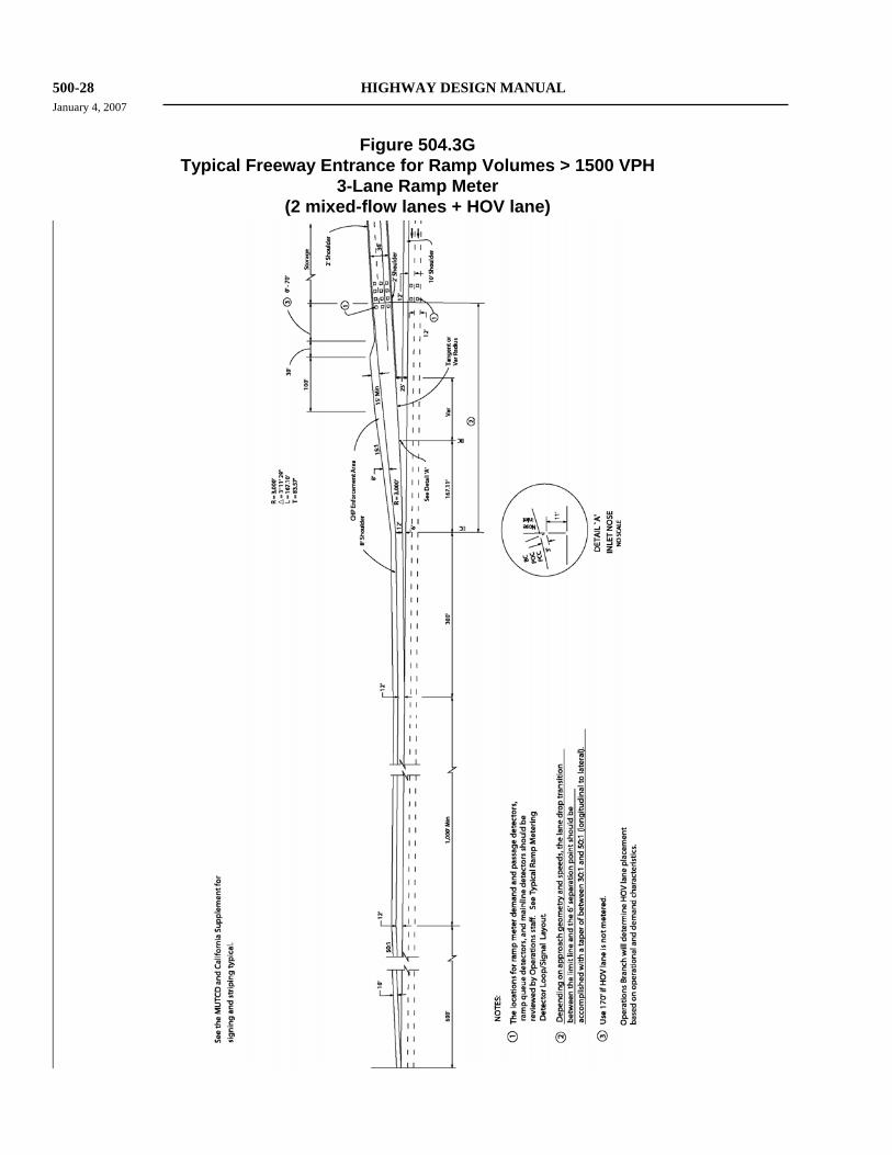
500-28 HIGHWAY DESIGN MANUAL January 4, 2007
Figure 504.3G Typical Freeway Entrance for Ramp Volumes > 1500 VPH
3-Lane Ramp Meter (2 mixed-flow lanes + HOV lane)
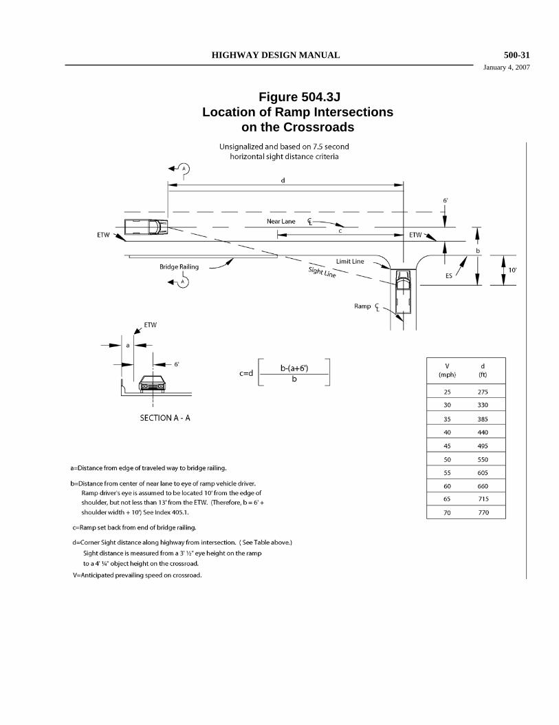
HIGHWAY DESIGN MANUAL 500-31 January 4, 2007
Figure 504.3J Location of Ramp Intersections
on the Crossroads
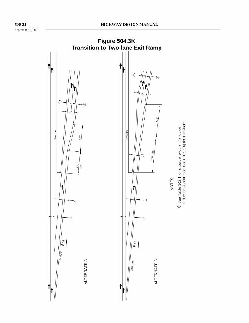
500-32 HIGHWAY DESIGN MANUAL September 1, 2006
Figure 504.3K Transition to Two-lane Exit Ramp
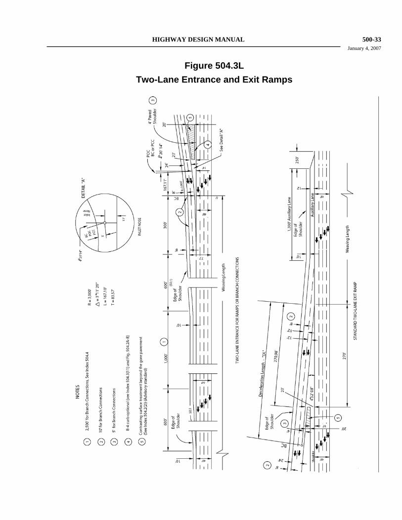
HIGHWAY DESIGN MANUAL 500-33 January 4, 2007
Figure 504.3L
Two-Lane Entrance and Exit Ramps
500-34 HIGHWAY DESIGN MANUAL September 1, 2006 Radii for loop ramps should normally range
from 150 feet to 200 feet. Increasing the radii beyond 200 feet is typically not cost effective as the slight increase in design speed is usually outweighed by the increased right of way requirements and the increased travel distance. Curve radii of less than 120 feet should also be avoided. Extremely tight curves lead to increased off-tracking by trucks and increase the potential for vehicles to enter the curve with excessive speed.
Of particular concern in the design of loop ramps are the constraints imposed on large trucks. Research indicates that trucks often enter loops with excessive speed, either due to inadequate deceleration on exit ramps or due to driver efforts to maintain speed on entrance ramps to facilitate acceleration and merging. Where the loop is of short radius and is also on a steep descent (over 6 percent), it is important to develop the standard 2/3 full superelevation rate by the beginning of the curve (see Index 504.2(5)). On loop entrance ramps this can often be facilitated by beginning the ramp with a short tangent (75 feet to 100 feet) that diverges from the cross street at an angle of 4 to 9 degrees. Consideration should be given to developing additional tangent length if conditions allow.
The ramp lane pavement structure should be provided on shoulders for curves with a radius less than 300 feet (see Indexes 626.1 and 636.1).
(9) Distance Between Successive On-ramps. The minimum distance between two successive on-ramps to a freeway lane should be the distance needed to provide the standard on-ramp acceleration taper shown on Figure 504.2A. This distance should be about 1,000 feet unless the upstream ramp adds an auxiliary lane in which case the downstream ramp should merge with the auxiliary lane in a standard 50:1 (longitudinal to lateral) convergence. The distance between on-ramp noses will then be controlled by interchange geometry.
(10) Distance Between Successive Exits. The minimum distance between successive exit
ramps for guide signing should be 1,000 feet on the freeway and 600 feet on collector-distributor roads.
(11) Curbs. Curbs should not be used on ramps except in the following locations:
(a) A Type D curb or 4-inch Type B curb (see Index 303.2) may be used on both sides of the separation between freeway lanes and a parallel collector-distributor road.
(b) A B4 curb may be used as shown in Figure 504.2A to control drainage or where the gore cross slope would be greater than allowed in Index 504.2(5). When the optional B4 curb is used at the entrance ramp inlet nose, the shoulder adjacent to the curb should be the same width as the ramp shoulder approaching the curb. The B4 gutter pan can be included as part of the shoulder width. As stated in Index 405.4(2), curbs are typically discouraged where design speeds are over 45 miles per hour. The appropriateness of curbs at gore areas must be determined on a case-by-case basis.
(c) Curbs may be used where necessary at the ramp connection with the local street for the protection of pedestrians, for channelization, and to provide compatibility with the local facility.
(d) The Type E curb may be used only in special drainage situations, for example, where drainage parallels and flows against the face of a retaining wall.
In general, curbs should not be used on the high side of ramps or in off-ramp gore areas except at collector-distributor roads. The offtracking of trucks should be analyzed when considering curbs on ramps.
(12) Dikes. Dikes may be used where necessary to control drainage. For additional information see Index 303.3.
504.4 Freeway-to-Freeway Connections (1) General. All of the design criteria discussed
in Indexes 501.3, 504.2 and 504.3 apply to
HIGHWAY DESIGN MANUAL 800-9 January 4, 2007
804.6 Responsibilities The District Project Engineer is generally the responsible party for initiating and coordinating the overall multi-disciplinary team activities of evaluation and documentation of floodplain impacts. Discussion of specific hydraulic and environmental aspects are required by 23 CFR 650, Subpart A. Preparing the project floodplain evaluation report and the summary for the environmental document or project report is normally the responsibility of the Environmental Planning Branch. The District Hydraulics Engineer will, as necessary, develop the hydrological and hydraulic information and provide technical assistance for assessing impacts of floodplain encroachments.
804.7 Preliminary Evaluation of Risks and Impacts for Environmental Document Phase Virtually all proposed highway improvements that are considered as floodplain encroachments will be designed to have:
(a) No significant risks associated with implementation and,
(b) Negligible environmental impacts on the base floodplain.
(1) Risks. There will always be some potential for property damage and flooding that may affect public safety, associated with highway drainage design. In a majority of cases, a field review with a NFIP or USGS map and the application of good engineering judgment are all that is needed to determine if such risks are significant or acceptable. The detail of study and documentation shall be commensurate with the risk(s) or floodplain impact(s) and, in all cases, should be held to the minimum necessary to address 23 CFR 650.111.
(2) Impacts. The assessment of potential impacts on the floodplain environment will include:
(a) Impacts on natural and beneficial floodplain values.
(b) Support of probable incompatible floodplain development.
Except for the more environmentally sensitive projects, a single visit to the project site by the
District Project Engineer, Hydraulics Engineer, and Environmental Planner, to assess and document the risks and environmental impacts associated with the proposed project is generally all that is necessary to obtain enough information for the "Location Hydraulic Study". Any reasonable adaptation of the technical information for “Location Hydraulic Study” form, Figure 804.7A, may be utilized to document and summarize the findings of the "Location Hydraulic Study" when the project is expected to be processed with a categorical exclusion. Items listed in 23 CFR 650.111 as follows must be addressed:
(a) National Flood Insurance Program (NFIP) maps or information developed by the highway agency, if NFIP maps are not available, shall be used to determine whether a highway location alternative will include an encroachment.
(b) Location studies shall include evaluation and discussion of the practicability of alternatives to any longitudinal encroachments.
(c) Location studies shall include discussion of the following items, commensurate with the significance of the risk or environmental impact, for all alternatives containing encroachments and for those actions which would support base flood-plain development:
(1) The risks associated with implementation of the action,
(2) The impacts on natural and beneficial floodplain values,
(3) The support of probable incompatible floodplain develop-ment,
(4) The measures to minimize flood-plain impacts associated with the action, and
(5) The measures to restore and preserve the natural and beneficial floodplain values impacted by the action.
800-10 HIGHWAY DESIGN MANUAL September 1, 2006
(d) Location studies shall include evaluation and discussion of the practicability of alternatives to any significant encroachments or any support of incompatible flood-plain development.
(e) The studies required by Sec. 650.111 (c) and (d) shall be summarized in environmental review documents prepared pursuant to 23 CFR part 771.
(f) Local, State, and Federal water resources and flood-plain management agencies should be consulted to determine if the proposed highway action is consistent with existing watershed and flood-plain management programs and to obtain current information on development and proposed actions in the affected watersheds.
Figure 804.7A is considered the suggested minimum hydraulic and engineering documentation for floodplain encroachments (bridge, culvert, channel change, slope protection, embankment, etc.). It is intended as a guide tool to help address the items listed in 23 CFR 650.111 and should be prepared jointly by the Project Engineer and Hydraulics Engineer. Since every location is unique, some of the questions may not apply, or additional considerations may need to be added.
For projects requiring an Environmental Impact Statement or Environmental Assessment (EIS/EA) or a finding of no significant impact (FONSI) with alternatives that have permanent features that encroach on the floodplain, a back-up report entitled Floodplain Evaluation is normally prepared by the District Environmental Branch. The technical requirements are typically developed jointly by the District Project Engineer and District Hydraulics Engineer. See Figure 804.7B for the Floodplain Evaluation Report Summary form that is used when an environmental document is to be prepared.
804.8 Design Standards The design standards for highways encroaching on a floodplain are itemized in 23 CFR, Section 650.115. One requirement often overlooked is the need to assess the costs and risks associated with the
overtopping flood for design alternatives in those instances where the overtopping flood exceeds the base flood. The content of design study information to be retained in the project file are described in 23 CFR, Section 650.117.
804.9 Coordination with the Local Community The responsibility for enforcing National Flood Insurance Program (NFIP) regulations rests with the local community that is participating in the NFIP. It is the community who must submit proposals to Federal Emergency Management Agency (FEMA) for amendments to NFIP ordinances and maps in that community, or to demonstrate that an alternative floodway configuration meets NFIP requirements. However, this responsibility may be borne by the agency proposing to construct the highway crossing. Therefore, the highway agency should deal directly with the community and, through them, deal with FEMA. Determination of the status of a community’s participation in the NFIP and review of applicable NFIP maps and study reports are, therefore, essential first steps in conducting location hydraulic studies and preparing environmental documents.
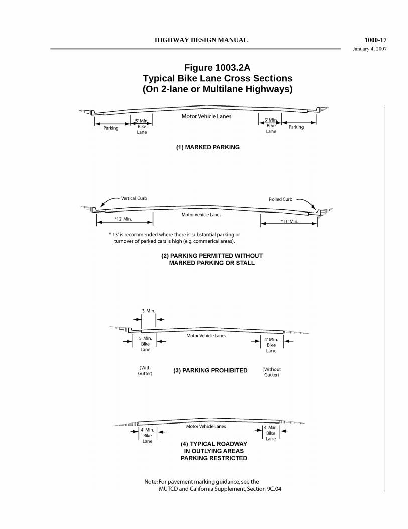
HIGHWAY DESIGN MANUAL 1000-17January 4, 2007
Figure 1003.2A
Typical Bike Lane Cross Sections (On 2-lane or Multilane Highways)
1000-18 HIGHWAY DESIGN MANUAL September 1, 2006 Figure 1003.2B illustrates a typical at-grade
intersection of multilane streets, with bike lanes on all approaches. Some common movements of motor vehicles and bicycles are shown. A prevalent type of accident involves straight-through bicycle traffic and right-turning motorists. Left-turning bicyclists also have problems, as the bike lane is on the right side of the street, and bicyclists have to cross the path of cars traveling in both directions. Some bicyclists are proficient enough to merge across one or more lanes of traffic, to use the inside lane or left-turn lane. However, there are many who do not feel comfortable making this maneuver. They have the option of making a two-legged left turn by riding along a course similar to that followed by pedestrians, as shown in the diagram. Young children will often prefer to dismount and change directions by walking their bike in the crosswalk.
(4) Interchange Design. As with bikeway design through at-grade intersections, bikeway design through interchanges should be accomplished in a manner that will minimize confusion by motorists and bicyclists. Designers should work closely with the local agency in designing bicycle facilities through interchanges. Local Agencies should carefully select interchange locations which are most suitable for bikeway designations and where the crossing meets applicable design standards. The local agency may have special needs and desires for continuity through interchanges which should be considered in the design process.
For Class II bikeway signing and lane markings, see the MUTCD and California Supplement, Section 9C.04.
The shoulder width shall not be reduced through the interchange area. The minimum shoulder width shall match the approach roadway shoulder width, but not less than 4 feet or 5 feet if a gutter exists. If the shoulder width is not available, the designated bike lane shall end at the previous local road intersection.
Depending on the intersection angles, either Figure 1003.2C or 1003.2D should also be used
for multilane ramp intersections. Additionally, the outside through lane should be widened to 14 feet when feasible. This allows extra room for bicycles to share the through lane with vehicles. The outside shoulder width should not be reduced through the interchange area to accommodate this additional width.
1003.3 Class III Bikeways Class III bikeways (bike routes) are intended to provide continuity to the bikeway system. Bike routes are established along through routes not served by Class I or II bikeways, or to connect discontinuous segments of bikeway (normally bike lanes). Class III facilities are shared facilities, either with motor vehicles on the street, or with pedestrians on sidewalks, and in either case bicycle usage is secondary. Class III facilities are established by placing Bike Route signs along roadways.
Minimum widths for Class III bikeways are not presented, as the acceptable width is dependent on many factors, including the volume and character of vehicular traffic on the road, typical speeds, vertical and horizontal alignment, sight distance, and parking conditions.
Since bicyclists are permitted on all highways (except prohibited freeways), the decision to designate the route as a bikeway should be based on the advisability of encouraging bicycle travel on the route and other factors listed below.
(1) On-street Bike Route Criteria. To be of benefit to bicyclists, bike routes should offer a higher degree of service than alternative streets. Routes should be signed only if some of the following apply:
(a) They provide for through and direct travel in bicycle-demand corridors.
(b) Connect discontinuous segments of bike lanes.
(c) An effort has been made to adjust traffic control devices (stop signs, signals) to give greater priority to bicyclists, as compared with alternative streets. This could include placement of bicycle-sensitive detectors on the right-hand portion of the road, where bicyclists are expected to ride.
HIGHWAY DESIGN MANUAL 1000-23September 1, 2006
the designated bike route shall end at the previous local road intersection.
1003.4 Bicycles on Freeways In some instances, bicyclists are permitted on freeways. Seldom would a freeway be designated as a bikeway, but it can be opened for use if it meets certain criteria. Essentially, the criteria involve assessing the safety and convenience of the freeway as compared with available alternate routes. However, a freeway should not be opened to bicycle use if it is determined to be incompatible. The Headquarters Traffic Liaisons and the Design Coordinator must approve any proposals to open freeways to bicyclists.
If a suitable alternate route exists, it would normally be unnecessary to open the freeway. However, if the alternate route is unsuitable for bicycle travel the freeway may be a better alternative for bicyclists. In determining the suitability of an alternate route, safety should be the paramount consideration. The following factors should be considered:
• Number of intersections • Shoulder widths • Traffic volumes • Vehicle speeds • Bus, truck and recreational vehicle
volumes • Grades • Travel time
When a suitable alternate route does not exist, a freeway shoulder may be considered for bicycle travel. Normally, freeways in urban areas will have characteristics that make it unfeasible to permit bicycle use. In determining if the freeway shoulder is suitable for bicycle travel, the following factors should be considered;
• Shoulder widths • Bicycle hazards on shoulders (drainage
grates, expansion joints, etc.) • Number and location of entrance/exit
ramps • Traffic volumes on entrance/exit ramps
• Bridge Railing height
When bicyclists are permitted on segments of freeway, it will be necessary to modify and supplement freeway regulatory signs, particularly those at freeway ramp entrances and exits, see the MUTCD and California Supplement, Section 9B.101.
Where no reasonable alternate route exists within a freeway corridor, the Department should coordinate with local agencies to develop or improve existing routes or provide parallel bikeways within or adjacent to the freeway right of way.
The long term goal is to provide a safe and convenient non-freeway route for bicycle travel.
1003.5 Multipurpose Trails In some instances, it may be appropriate for agencies to develop multipurpose trails - for hikers, joggers, equestrians, bicyclists, etc. Many of these trails will not be paved and will not meet the standards for Class I bikeways. As such, these facilities should not be signed as bikeways. Rather, they should be designated as multipurpose trails (or similar designation), along with regulatory signing to restrict motor vehicles, as appropriate.
If multipurpose trails are primarily to serve bicycle travel, they should be developed in accordance with standards for Class I bikeways. In general, multipurpose trails are not recommended as high speed transportation facilities for bicyclists because of conflicts between bicyclists and pedestrians. Wherever possible, separate bicycle and pedestrian paths should be provided. If this is not feasible, additional width, signing and pavement markings should be used to minimize conflicts.
It is undesirable to mix mopeds and bicycles on the same facility. In general, mopeds should not be allowed on multipurpose trails because of conflicts with slower moving bicyclists and pedestrians. In some cases where an alternate route for mopeds does not exist, additional width, signing, and pavement markings should be used to minimize conflicts. Increased patrolling by law enforcement personnel is also recommended to enforce speed limits and other rules of the road.
It is usually not desirable to mix horses and bicycle traffic on the same multipurpose trail. Bicyclists are often not aware of the need for slower speeds and additional operating space near horses. Horses
1000-24 HIGHWAY DESIGN MANUAL January 4, 2007 can be startled easily and may be unpredictable if they perceive approaching bicyclists as a danger. In addition, pavement requirements for safe bicycle travel are not suitable for horses. For these reasons, a bridle trail separate from the multipurpose trail is recommended wherever possible.
1003.6 Miscellaneous Bikeway Criteria The following are miscellaneous bikeway criteria which should be followed to the extent pertinent to Class I, II and III bikeways. Some, by their very nature, will not apply to all classes of bikeway. Many of the criteria are important to consider on any highway where bicycle travel is expected, without regard to whether or not bikeways are established.
(1) Bridges. Bikeways on highway bridges must be carefully coordinated with approach bikeways to make sure that all elements are compatible. For example, bicycle traffic bound in opposite directions is best accommodated by bike lanes on each side of a highway. In such cases, a two-way bike path on one side of a bridge would normally be inappropriate, as one direction of bicycle traffic would be required to cross the highway at grade twice to get to and from the bridge bike path. Because of the inconvenience, many bicyclists will be encouraged to ride on the wrong side of the highway beyond the bridge termini.
The following criteria apply to a two-way bike path on one side of a highway bridge:
(a) The bikeway approach to the bridge should be by way of a separate two-way facility for the reason explained above.
(b) A physical separation, such as a chain link fence or railing, shall be provided to offset the adverse effects of having bicycles traveling against motor vehicle traffic. The physical separation should be designed to minimize fixed end hazards to motor vehicles and if the bridge is an interchange structure, to minimize sight distance restrictions at ramp intersections.
It is recommended that bikeway bridge railings or fences placed between traffic lanes and bikeways be at least 54 inches high to
minimize the likelihood of bicyclists falling over the railings. Standard bridge railings which are lower than 46 inches can be retrofitted with lightweight upper railings or chain link fence suitable to restrain bicyclists. See Index 208.10(6) for guidance regarding bicycle railing on bridges.
Separate highway overcrossing structures for bikeway traffic shall conform to Department standard pedestrian overcrossing design loading. The minimum clear width shall be the paved width of the approach bikeway but not less than 8 feet. If pedestrians are to use the structure, additional width is recommended.
(2) Surface Quality. The surface to be used by bicyclists should be smooth, free of potholes, and the pavement edge uniform. For rideability on new construction, the finished surface of bikeways should not vary more than ¼ inch from the lower edge of an 8-foot long straight edge when laid on the surface in any direction.
Table 1003.6 indicates the recommended bikeway surface tolerances for Class II and III bikeways developed on existing streets to minimize the potential for causing bicyclists to lose control of their bicycle (Note: Stricter tolerances should be achieved on new bikeway construction.) Shoulder rumble strips are not suitable as a riding surface for bicycles. See the MUTCD and California Supplement, Chapter 3B for additional information regarding rumble strip design considerations for bicycles.
(3) Drainage Grates, Manhole Covers, and Driveways. Drainage inlet grates, manhole covers, etc., on bikeways should be designed and installed in a manner that provides an adequate surface for bicyclists. They should be maintained flush with the surface when resurfacing.
HIGHWAY DESIGN MANUAL 1100-5 January 4, 2007
line should be parallel to the profile grade of the soundwall.
• If the soundwall is on a concrete barrier, the Top of Concrete Barrier line must be constant height above the profile grade and the Bottom of Concrete Barrier line should be shown on the plans.
• If the soundwall is on a Retaining Wall, the Top of Retaining Wall line or the Bottom of Footing line and Retaining Wall height should be shown on the plans.
• The original ground (OG) line and any known utilities should be shown on the Soundwall Plan sheets.
(3) Pay Quantities. Soundwalls are to be measured by the square foot between the elevation lines shown on the plans and the length of the wall. Soundwall footings are to be paid as minor concrete and concrete barriers are to be paid for as concrete barrier (modified). Piles are to be paid for separately to facilitate minor changes in the field.
Refer to the Standard Special Provisions for more information on measurement and pay quantities.
When calculating costs for determining “reasonableness,” all pay quantities associated with the proposed soundwalls should be included in the analysis. Refer to the California Traffic Noise Analysis Protocol for a discussion on this topic.
(4) Working Drawings. Working Drawings are no longer required for state designed masonry block soundwalls in view of the fact that all the information necessary to construct the wall should be shown in the contract plans. The Special Provisions for Alternative Soundwall systems should require the successful bidder to submit four (4) sets of drawings for initial review and between six (6) and twelve (12) additional sets, as requested by the Engineer, for final approval and use during construction. Refer to Bridge Reference Specification 51-561(51SWAL) for more information.
(5) Preliminary Site Data. In using the "Top of Soundwall/Bottom of Concrete Barrier" line concept, it is important that the preliminary site data be as complete as possible. To eliminate or minimize construction change orders the following guidance is provided:
• Provide accurate ground line profiles.
• Select only standard or pre-approved design alternative soundwall types.
• Provide adequate information based on foundation investigation.
• Locate overhead and underground utilities.
• Review drainage and show any modifications on the plans.
• Determine and specify architectural treatment.
• Determine the need for special design, and coordinate with the Office of Structures Design during the early stages of design.
1102.6 Noise Barrier Aesthetics (1) General. A landscaped earth berm or a
combination wall and berm tend to minimize the apparent noise barrier height and are an aesthetically acceptable alternative among noise barrier options; however, these alternatives are not always suitable for many sites due to limited space.
Some additional cost to enhance the aesthetic quality of the noise barrier is usually warranted. Early community involvement toward proposing aesthetic treatment improvements on noise barriers is recommended to accommodate contextual considerations. However, accountability for designs that significantly increase the cost of the noise barrier should be a topic for discussion early in the design process.
Soundwalls should not be designed with abrupt beginnings or ends. Generally, the ends of the soundwall should be tapered or stepped if the height of the soundwall exceeds 6 feet. See Standard Plans for further details. Consult the District Landscape Architect regarding the design of tapers or stepped ends,
1100-6 HIGHWAY DESIGN MANUAL September 1, 2006
aesthetic treatment, highway planting and landscaping adjacent to noise barriers.
(2) Aesthetic Treatment. Standard aesthetic treatments have been developed by the DES Office of Structure Design for the various alternative materials.
When treatment that is not a standard aesthetic treatment is proposed for noise barriers, contact the District Landscape Architect for selection of the most appropriate treatment. The Headquarters Traffic Liaison should be consulted in these instances to ensure that the treatment of choice satisfies all safety requirements.
(3) Planting Near Noise Barriers. The use of plants in conjunction with noise barriers can help to combat graffiti and enhance public acceptance of the noise barrier. When landscaping is to be placed adjacent to the soundwall, which will eventually screen a substantial portion of the wall, only minimal aesthetic treatment is justified.
See Index 902.3 and the Project Development Procedures Manual for additional information.
1102.7 Maintenance Consideration in Noise Barrier Design (1) General. Noise barriers placed within the area
between the shoulder and right of way line complicate the ongoing maintenance operations. When there is a substantial distance behind the noise barriers and in front of the right of way line, special consideration is required. If the adjoining land is occupied with streets, roads, parks, or other large parcels, an effort should be made during the right of way negotiations to have the abutting property owners maintain the area. In this case, the chain link fence at the right of way line would not be required. Maintenance by others may not be practical if a number of small individual properties abut the noise barrier.
(2) Access Requirements. Access to the back side of the noise barrier must be provided if the area is to be maintained by the Department. In subdivided areas, access can be via local
streets, when available. If access is not available via local streets, access gates or openings are essential at intervals along the noise barrier. Access may be provided via offsets in the barrier. Offset barriers must be overlapped a minimum of 2.5 to 3 times the offset distance in order to maintain the integrity of the sound attenuation of the main barrier. Location of the access openings must be coordinated with the District maintenance office.
(3) Noise Barrier Material. The alternative materials selected for the noise barrier should be appropriate for the environment in which it is placed. For walls that are located at or near the edge of shoulder, the portion of the noise barrier located above the safety-shape concrete barrier should be capable of withstanding the force of an occasional vehicle which may ride up above the top of the safety barrier.
1102.8 Emergency Access Considerations in Noise Barrier Design (1) General. In addition to access gates being
constructed in noise barriers to satisfy the Department’s maintenance needs, they may also be constructed to provide a means to access the freeway in the event of a catastrophic event which makes the freeway impassable for emergency vehicles. These gates are not intended to be used as an alternate means of emergency access to adjacent neighborhoods. Access to those areas should be planned and provided from the local street system. Small openings may also be provided in the noise barrier which would allow a fire hose to be passed through it. Local emergency response agencies should be contacted early in the design process to determine the need for emergency access gates and fire hose openings.
(2) Emergency Access Gate Requirements. Access gates in noise barriers should be kept to a minimum and should be at least 1,000 feet apart. Locations of access should be coordinated with the District Maintenance office. Only one opening should be provided at locations where there is a need for access


![CALIFORNIA JUDGES BENCHGUIDES 1 california judges benchguides benchguide 201 child and spousal support i. [§201.1] scope of benchguide ii. [§201.2] application to registered domestic](https://img.pdfslide.us/doc/110x75/5aa49eca7f8b9a517d8c24b8/california-judges-benchguides-1-california-judges-benchguides-benchguide-201.jpg)