Embed Size (px)
Citation preview

Design Intent ‐ Workbookby
Kirk Barnes, CSWA
3‐D Parametric Modeling problems with design intent

Plate with Hole Create the following part using the information and dimensionsgiven.All sketches should be fully defined.
Design Intent Use the design intent to create the part.1. The part is not symmetrical. 2. The origin is undefined.3. The hole is a through hole.4. The two square features (2.0 X 2.0) are coplanar and are
controlled by one sketch.
Dimensions Use the following graphics with the design intent to create thepart.Dimensions are in inches.
Hint • Blind Base Extrude• Through All end condition
Design Intent ‐ Workbook 2

Bracket Create the following part using the information and dimensionsgiven.All sketches should be fully defined.
Design Intent Use the design intent to create the part.1. Origin is at the center of the rounded end.2. The boss is centered on the rounded end of the base
feature.3. The octagon is a through all feature and the n48 inscribed
circle is concentric to the boss.4. The two n10 holes are through holes and are symmetrical
about the centerline of the part.
Dimensions Use the following graphics with the design intent to create thepart. Dimensions are in millimeters.
The 150 mm dimension is tothe center of the roundedend.
Hint • The use of centerlines (construction line) is required forsymmetry relations.
Design Intent ‐ Workbook 3

Locator Create the following part using the information and dimensionsgiven.All sketches should be fully defined.
Design Intent Use the design intent to create the part.1. The origin is at the lower‐left front corner.2. The part is not symmetrical. 3. The holes are through holes.
Dimensions Use the following graphics with the design intent to create thepart.Dimensions are in millimeters.
Hint • Equal relations• Link Values
Start with a base feature200 mm X 100 mm X 100 mm(W X D X H)
Use three (3), ø120 cutfeatures centered at theappropriate corners of theblock.
Next page
Design Intent ‐ Workbook 4

Add a 20 mm radius fillet tothe two edges.
Design Intent ‐ Workbook 5

Sketching and DesignIntent
Create this part using the information and dimensions provided.Sketch and extrude profiles to create the part.All sketches should be fully defined.
Design Intent 1. Origin is undefined2. The part is symmetrical3. The 45o Angle remains constant as the length (C
dimension) of the part increases.
Dimensions A = 45o B = 2.00 C = 3.50
1. Open a new part using the ANSI_Inch template.2. Create the base sketch on the Front plane using lines and
relations.3. Dimension to capture the design intent.
Hint Mid Plane extrude
Design Intent ‐ Workbook 6

Step Block Create this part using the information and dimensions provided.Sketch and extrude profiles to create the part.All sketches should be fully defined.
Design Intent 1. Origin is undefined2. All sketches are full defined3. The two holes go all the way through (Through All)4. The two holes are controlled by one dimension. (Equal)5. As the block increases in depth (2.00 dimension) the two
holes remain centered.
Dimensions A = Ø.75 B = 3.00 C = B D = ½C
1. Open a new part using the ANSI_Inch template.2. Create the base sketch on the Front plane using lines and
relations.3. Dimension to capture the design intent.
Hint Construction linesMidpoint sketch relationsEqual sketch relations
Design Intent ‐ Workbook 7
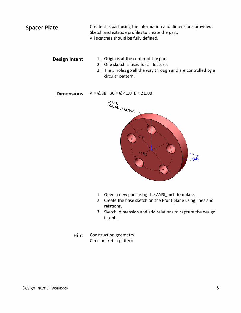
Spacer Plate Create this part using the information and dimensions provided.Sketch and extrude profiles to create the part.All sketches should be fully defined.
Design Intent 1. Origin is at the center of the part2. One sketch is used for all features3. The 5 holes go all the way through and are controlled by a
circular pattern.
Dimensions A = Ø.88 BC = Ø 4.00 E = Ø6.00
1. Open a new part using the ANSI_Inch template.2. Create the base sketch on the Front plane using lines and
relations.3. Sketch, dimension and add relations to capture the design
intent.
Hint Construction geometryCircular sketch pattern
Design Intent ‐ Workbook 8

Bearing Stock Create two versions of the given part using the information anddimensions provided. All sketches should be fully defined.
Save as EX04_VerA and EX04_VerB
Design Intent Version A1. Origin is at the center of the part2. As the outside diameter (A) increases, the inside diameter
(B) remains constant.
Version B1. Origin is at the center of the part.2. As the outside diameter (A) increases, the inside diameter
(B) maintains the original edge clearance.
Dimensions A = Ø3.00 B = Ø1.50
1. Open a new part using the ANSI_Inch template.2. Create the base sketch on the Front plane.3. Sketch, dimension and/or add relations to capture the
design intent.
Hint Edge distance=Outside Dia−Inside Dia2
Automatic relations
Design Intent ‐ Workbook 9

Spacer Create this part using the information and dimensions provided.Sketch and extrude profiles to create the part. All sketches shouldbe fully defined.
Design Intent 1. Origin is at the center of the part.2. The part is symmetrical.3. As the outside diameter (OD) increases the inside
diameter (ID) remains constant.4. The .76” horizontal slot remains centered as the OD is
increased and the depth remains .38”.5. The .38” slot feature in the edge of the part remains .50”
from the back edge.
Dimensions Use the drawing below and the required design intent to createthe spacer.
1. Open a new part using the ANSI_Inch template.2. Create the base sketch on the Front plane using lines and
relations.3. Sketch, dimension and add relations to capture the design
intent.
Hint • Construction geometry• Offset Entities
Design Intent ‐ Workbook 10

Wedge Create this part using the information and dimensions provided.Sketch and extrude profiles to create the part. All sketches shouldbe fully defined.
Design Intent 1. Origin is at the center of the part.2. The part is symmetrical with respect to its mid plane3. This part is built with one base feature and two cut
features.4. The Ø1.50 hole is perpendicular to the bottom of the
wedge and remains centered on the part.
Dimensions Use the drawing below and the required design intent to createthe wedge.
Note: The 1.25 dimension is to the center of the circular cutfeature.
Hint Mid Plane end condition
Design Intent ‐ Workbook 11

Link Create this part using the information and dimensions provided.Sketch and extrude profiles to create the part. All sketches shouldbe fully defined.
Design Intent 1. The part is symmetrical 2. Plate thickness is centered on circular end.3. All fillets are equal in radius.4. All holes are through holes.5. As the length of the cylindrical feature increases the slot
feature remains centered and remains the same width.
Dimensions Use the drawing below and the required design intent to createthe spacer.
1. This part has no dimensions given. Model this part onshape and proportion only.
Hint Origin location and Mid Plane extrude
Design Intent ‐ Workbook 12

Guide Roller Create this part using the information and dimensions provided.Sketch and extrude profiles to create the part. All sketches shouldbe fully defined.
Design Intent 1. Origin is at the center of the part.2. The hole is a through hole.
3. As the Ø57 increases the 120~ angle is maintained.
Dimensions Use the drawing below and the required design intent to createthe spacer.
Hint Mid Plane extrudeRevolve Cut
Design Intent ‐ Workbook 13

Adjustable Link Create this part using the information and dimensions provided.Sketch and extrude profiles to create the part. All sketches shouldbe fully defined.
Design Intent 1. Origin is at the center of the part.2. The part is symmetrical.3. As the 3.00 center‐to‐center hole dimension is increased
the part remains symmetrical and the slot increasesproportionally.
Dimensions Use the drawing below and the required design intent to createthe spacer.
1. Directions
Hint Mid Plane extrude
Design Intent ‐ Workbook 14

Locating Block9.11.1.b
Create this part using the information and dimensions provided.Sketch and extrude profiles to create the part. All sketches shouldbe fully defined.
Design Intent 1. Origin is at the front‐center of the part. 2. The part is symmetrical.3. As the height (2.50”) increases, the bottom edge of the
sloped surface remains 1.25” from the top surface.
Dimensions Use the drawing below and the required design intent to createthe spacer.
1. The four lugs are .88 X .63 X .50
1. The base feature is sketched on the top plane.2. Mirror feature can be used to capture design intent for
the 4 lugs.
Hint Extrusion at angle to sketchReference sketch
Design Intent ‐ Workbook 15

Spacer Create this part using the information and dimensions provided.Sketch and extrude profiles to create the part. All sketches shouldbe fully defined.
Design Intent 1. Origin is at the center of the part.2. As the Ø2.00 feature increases in size the Ø1.50 feature
increases proportionally. Create an equation controllingthe relationship between the two features.
Dimensions Use the drawing below and the required design intent to createthe spacer.
1. Use Revolved Feature2. Dimensioning from visible lines to the centerline in a
sketch gives diameter dimensions.
Design Intent ‐ Workbook 16

Link Arm14.3.5
Create this part using the information and dimensions provided.Sketch and extrude profiles to create the part. All sketches shouldbe fully defined.
Design Intent 1. Origin is at the center of the Ø3.188 boss.2. The part is not symmetrical.3. As the Ø1.500 boss depth increases the Ø.438 hole
feature remains fixed in the original location.
Dimensions Use the drawing below and the required design intent to createthe Link Arm.
1. Use multibody bridging to join the two bosses with acenter web feature.
2. Apply draft to the center feature.
Hint Multibody solidsDraft (neutral plane)Reference planesOffset sketch from plane
Design Intent ‐ Workbook 17

Bracket‐4 Create this part using the information and dimensions provided.Sketch and extrude profiles to create the part. All sketches shouldbe fully defined. Use your inch part template to begin.
Design Intent 1. Origin is at the center of the part.2. The part is symmetrical.3. Material: Brass 4. The holes are centered and always go completely through
the part.
Dimensions Use the drawing below and the required design intent to createthe Bracket‐4.
• Check that the standard orthographic views appear thesame as in the figure.
• Make a B size decimal dimensioned drawing
Hint Possibly helpful tools are: Mirror, Convert Entities, Offset Entities,Trim.
Design Intent ‐ Workbook 18

Design Intent ‐ Workbook 19