Embed Size (px)
Citation preview
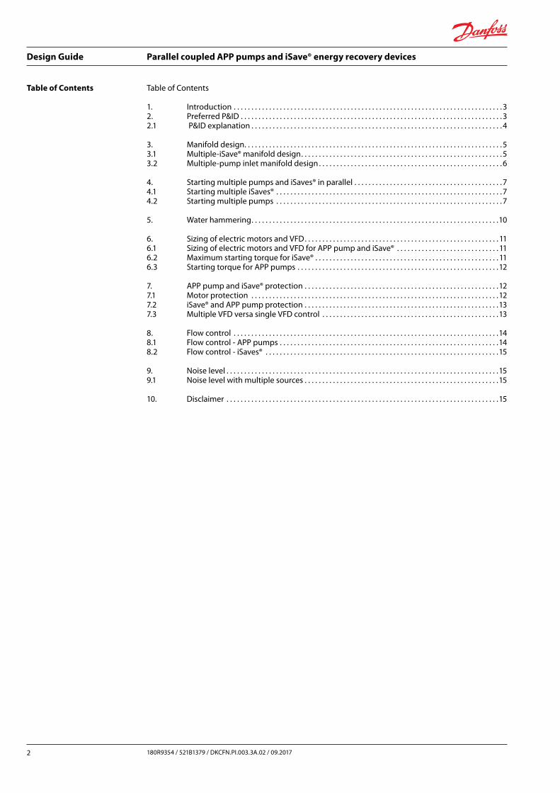
Design Guide
Parallel coupled APP pumpsand iSave® energy recovery devices
Design Guide
Parallel coupled APP pumpsand iSave® energy recovery devices
hpp.danfoss.com
Design Guide Parallel coupled APP pumps and iSave® energy recovery devices
2 180R9354 / 521B1379 / DKCFN.PI.003.3A.02 / 09.2017
Table of Contents Table of Contents
1. Introduction . . . . . . . . . . . . . . . . . . . . . . . . . . . . . . . . . . . . . . . . . . . . . . . . . . . . . . . . . . . . . . . . . . . . . . . . . . . . 32. Preferred P&ID . . . . . . . . . . . . . . . . . . . . . . . . . . . . . . . . . . . . . . . . . . . . . . . . . . . . . . . . . . . . . . . . . . . . . . . . . . 32.1 P&ID explanation . . . . . . . . . . . . . . . . . . . . . . . . . . . . . . . . . . . . . . . . . . . . . . . . . . . . . . . . . . . . . . . . . . . . . . . 4
3. Manifold design. . . . . . . . . . . . . . . . . . . . . . . . . . . . . . . . . . . . . . . . . . . . . . . . . . . . . . . . . . . . . . . . . . . . . . . . . 53.1 Multiple-iSave® manifold design. . . . . . . . . . . . . . . . . . . . . . . . . . . . . . . . . . . . . . . . . . . . . . . . . . . . . . . . . 53.2 Multiple-pump inlet manifold design . . . . . . . . . . . . . . . . . . . . . . . . . . . . . . . . . . . . . . . . . . . . . . . . . . . . 6
4. Starting multiple pumps and iSaves® in parallel . . . . . . . . . . . . . . . . . . . . . . . . . . . . . . . . . . . . . . . . . . 74.1 Starting multiple iSaves® . . . . . . . . . . . . . . . . . . . . . . . . . . . . . . . . . . . . . . . . . . . . . . . . . . . . . . . . . . . . . . . . 74.2 Starting multiple pumps . . . . . . . . . . . . . . . . . . . . . . . . . . . . . . . . . . . . . . . . . . . . . . . . . . . . . . . . . . . . . . . . 7
5. Water hammering. . . . . . . . . . . . . . . . . . . . . . . . . . . . . . . . . . . . . . . . . . . . . . . . . . . . . . . . . . . . . . . . . . . . . .10
6. Sizing of electric motors and VFD. . . . . . . . . . . . . . . . . . . . . . . . . . . . . . . . . . . . . . . . . . . . . . . . . . . . . . . 116.1 Sizing of electric motors and VFD for APP pump and iSave® . . . . . . . . . . . . . . . . . . . . . . . . . . . . . 116.2 Maximum starting torque for iSave® . . . . . . . . . . . . . . . . . . . . . . . . . . . . . . . . . . . . . . . . . . . . . . . . . . . . 116.3 Starting torque for APP pumps . . . . . . . . . . . . . . . . . . . . . . . . . . . . . . . . . . . . . . . . . . . . . . . . . . . . . . . . .12
7. APP pump and iSave® protection . . . . . . . . . . . . . . . . . . . . . . . . . . . . . . . . . . . . . . . . . . . . . . . . . . . . . . .127.1 Motor protection . . . . . . . . . . . . . . . . . . . . . . . . . . . . . . . . . . . . . . . . . . . . . . . . . . . . . . . . . . . . . . . . . . . . . .127.2 iSave® and APP pump protection . . . . . . . . . . . . . . . . . . . . . . . . . . . . . . . . . . . . . . . . . . . . . . . . . . . . . . .137.3 Multiple VFD versa single VFD control . . . . . . . . . . . . . . . . . . . . . . . . . . . . . . . . . . . . . . . . . . . . . . . . . .13
8. Flow control . . . . . . . . . . . . . . . . . . . . . . . . . . . . . . . . . . . . . . . . . . . . . . . . . . . . . . . . . . . . . . . . . . . . . . . . . . .148.1 Flow control - APP pumps . . . . . . . . . . . . . . . . . . . . . . . . . . . . . . . . . . . . . . . . . . . . . . . . . . . . . . . . . . . . . .148.2 Flow control - iSaves® . . . . . . . . . . . . . . . . . . . . . . . . . . . . . . . . . . . . . . . . . . . . . . . . . . . . . . . . . . . . . . . . . .15
9. Noise level . . . . . . . . . . . . . . . . . . . . . . . . . . . . . . . . . . . . . . . . . . . . . . . . . . . . . . . . . . . . . . . . . . . . . . . . . . . . .159.1 Noise level with multiple sources . . . . . . . . . . . . . . . . . . . . . . . . . . . . . . . . . . . . . . . . . . . . . . . . . . . . . . .15
10. Disclaimer . . . . . . . . . . . . . . . . . . . . . . . . . . . . . . . . . . . . . . . . . . . . . . . . . . . . . . . . . . . . . . . . . . . . . . . . . . . . .15
Design Guide Parallel coupled APP pumps and iSave® energy recovery devices
3180R9354 / 521B1379 / D KCFN.PI.003.3A.02 / 09.2017
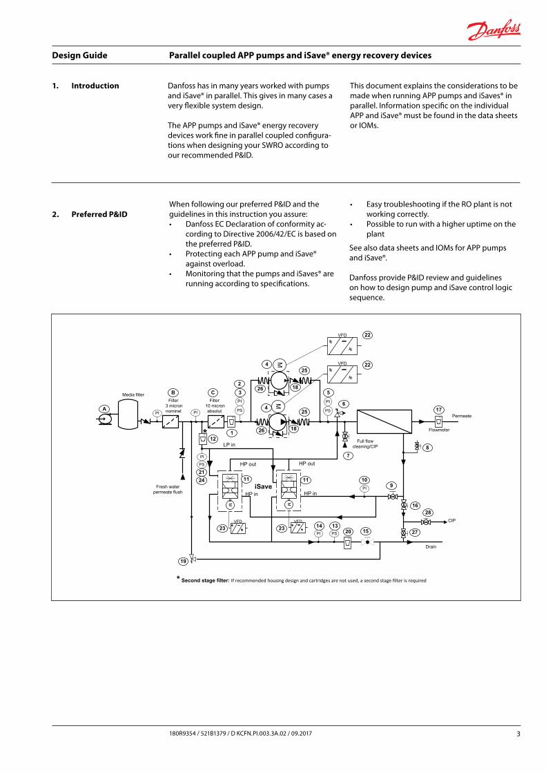
1. Introduction This document explains the considerations to be made when running APP pumps and iSaves® in parallel. Information specific on the individual APP and iSave® must be found in the data sheets or IOMs.
2. Preferred P&ID
See also data sheets and IOMs for APP pumps and iSave®.
Danfoss provide P&ID review and guidelines on how to design pump and iSave control logic sequence.
When following our preferred P&ID and the guidelines in this instruction you assure: • Danfoss EC Declaration of conformity ac-
cording to Directive 2006/42/EC is based on the preferred P&ID.
• Protecting each APP pump and iSave® against overload.
• Monitoring that the pumps and iSaves® are running according to specifications.
• Easy troubleshooting if the RO plant is not working correctly.
• Possible to run with a higher uptime on the plant
Danfoss has in many years worked with pumps and iSave® in parallel. This gives in many cases a very flexible system design.
The APP pumps and iSave® energy recovery devices work fine in parallel coupled configura-tions when designing your SWRO according to our recommended P&ID.
Media filter
M
Permeate
iSave
F
F F
Flowmeter
VFD
M
HP in
HP out
VFD
M
HP in
HP out
VFD
Fresh water permeate flush
Full flow cleaning/CIP
6
7
17
8
9
271513
101111
12
19
Filter3 micron nominel
Filter10 micron absolut
Drain
4
18
5
M4
18
VFD
LP in
20
F
*
* Second stage filter: If recommended housing design and cartridges are not used, a second stage filter is required
1
21
2
PS
PI
PS
PI
PS
14PI
PIPI
PI
PI
3
A
B C
22
22
PS
24
23 23
25
25
26
26
16
CIP
28
Design Guide Parallel coupled APP pumps and iSave® energy recovery devices
4 180R9354 / 521B1379 / DKCFN.PI.003.3A.02 / 09.2017
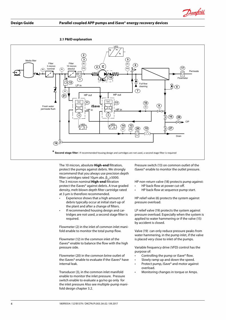
2.1 P&ID explanation
Media filter
M
Permeate
iSave
F
F F
Flowmeter
VFD
M
HP in
HP out
VFD
M
HP in
HP out
VFD
Fresh water permeate flush
Full flow cleaning
6
7
17
8
9
16
1513
101111
12
19
Filter3 micron nominel
Filter10 micron absolut
Drain
4
18
5
LP in
20
F
*
* Second stage filter: If recommended housing design and cartridges are not used, a second stage filter is required
1
21
2
PS
PI
PS
PI
PS
14PI
PIPI
PI
PI
3
27
CIP
28
The 10 micron, absolute High-end filtration, protect the pumps against debris. We strongly recommend that you always use precision depth filter cartridges rated 10μm abs. β
10≥5000.
The 3 micron nominal High-end filtration protect the iSaves® against debris. A true graded density, melt-blown depth filter cartridge rated at 3 μm is therefore recommended.• Experience shows that a high amount of
debris typically occur at initial start-up of the plant and after a change of filters.
• If recommended housing design and car-tridges are not used, a second stage filter is required.
Flowmeter (2) in the inlet of common inlet mani-fold enable to monitor the total pump flow.
Flowmeter (12) in the common inlet of the iSaves® enable to balance the flow with the high pressure side.
Flowmeter (20) in the common brine outlet of the iSaves® enable to evaluate if the iSaves® have internal leak.
Transducer (3), in the common inlet manifold enable to monitor the inlet pressure. Pressure switch enable to evaluate a go/no go only for the inlet pressure Also see multiple-pump mani-fold design chapter 3.2.
Pressure switch (13) on common outlet of the iSaves® enable to monitor the outlet pressure.
HP non-return valve (18) protects pump against:• HP back-flow at power cut-off.• HP back-flow at sequence pump start.
HP relief valve (6) protects the system against pressure overload.
LP relief valve (19) protects the system against pressure overload. Especially when the system is applied to water hammering or if the valve (15) by accident is closed.
Valve (19) can only reduce pressure peaks from water hammering, in the pump inlet, if the valve is placed very close to inlet of the pumps.
Variable frequency drive (VFD) control has the purpose of:• Controlling the pump or iSave® flow.• Slowly ramp up and down the speed.• Protect pump, iSave® and motor against
overload.• Monitoring changes in torque or Amps.

Design Guide Parallel coupled APP pumps and iSave® energy recovery devices
5180R9354 / 521B1379 / D KCFN.PI.003.3A.02 / 09.2017
3.1 Multiple-iSave® manifold design
The purpose of the manifold is to distribute the flow to each iSave®.• Without generating cavitation, erosion and
air bubbles in the water.• With minimum pressure drop.• Assuring equal pressure into each iSave®
inlet port.
Each iSave® has a HP circulation pump included in the design. This means:• The flow through the HP side of the iSave® is
controlled by the HP circulation pump. This means that equal pressure drop across each iSave® is not critical. The velocity in the HP manifolds may be as high as 5 m/s.
• The flow through the LP side of the iSave® is controlled by the pressure difference
between LPfeed
and LPout
. This means that the pressure drop across each iSave® is critical to assure equal flow distribution.
• With “Z” flow scheme, flow enters on one side of the array and leaves on the other.
• With “U” scheme, flow enters and leaves the array from the same side. Based on same diameter calculations, a “U” flow array always provides more even flow distribution among the iSave® units than a “Z” array.
• Market experience shows that inlet velocity is limited to less than 3.7 m/s for a “U” and less than 2.1 m/s for a “Z” flow scheme.
3. Manifold design
iSave
iSave
iSave
iSave
iSave
iSave
iSave
iSave
Typical, manifold for multiple iSaves® are made in hard piping, using flexible couplings as connec-tion to the iSave® discharge and inlet.Experience in the market shows that precise welding of a steel manifold with multiple con-nections is difficult. The individual position of the manifold connections may exceed the flexibility of a single flexible coupling. To reduce stress on the iSave® discharge and inlet it is preferred to use flexible hoses or a minimum of 2 flexible couplings combined on the same pipe connecting to each iSave® discharge and inlet.
• Do not use the iSave® discharge or inlet con-nectors as support for pipes. The pipes must have separate support.
• Do not force any misaligned pipes to con-nect to the iSave® discharge or inlet.
Follow instruction from flexible coupling supplieror see Design Guide 180R9367 Piping connec-tions.
“Z” flow scheme max. 2.1 m/s
“U” flow scheme max. 3.7 m/s
Manifold alignment and end load
Design Guide Parallel coupled APP pumps and iSave® energy recovery devices
6 180R9354 / 521B1379 / DKCFN.PI.003.3A.02 / 09.2017
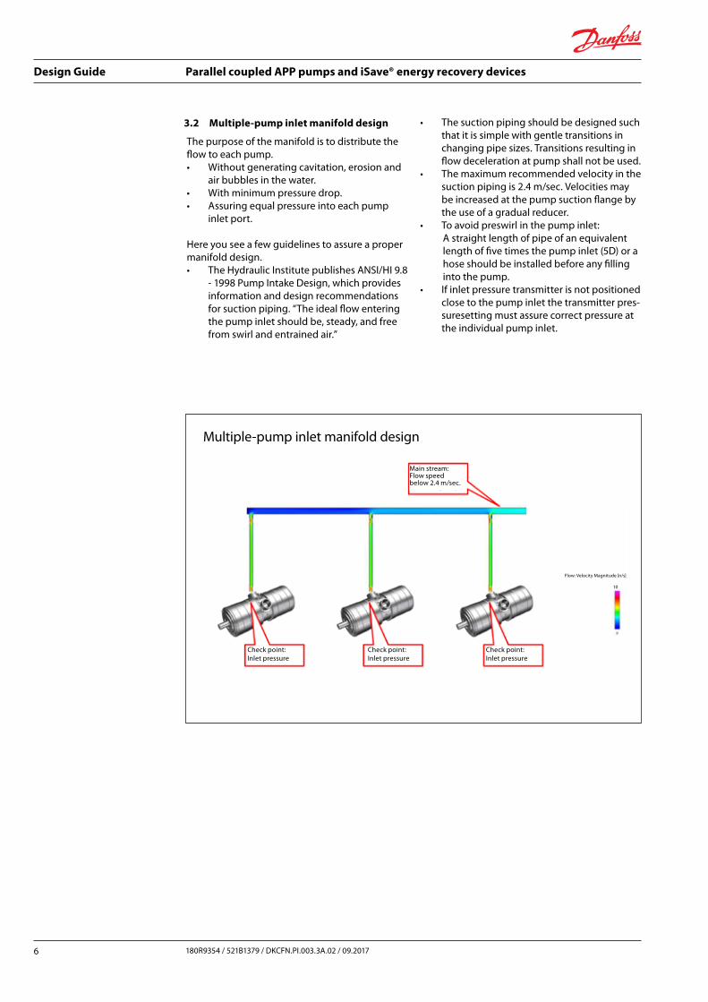
3.2 Multiple-pump inlet manifold design
The purpose of the manifold is to distribute the flow to each pump.• Without generating cavitation, erosion and
air bubbles in the water.• With minimum pressure drop.• Assuring equal pressure into each pump
inlet port.
Here you see a few guidelines to assure a proper manifold design.• The Hydraulic Institute publishes ANSI/HI 9.8
- 1998 Pump Intake Design, which provides information and design recommendations for suction piping. “The ideal flow entering the pump inlet should be, steady, and free from swirl and entrained air.”
• The suction piping should be designed such that it is simple with gentle transitions in changing pipe sizes. Transitions resulting in flow deceleration at pump shall not be used.
• The maximum recommended velocity in the suction piping is 2.4 m/sec. Velocities may be increased at the pump suction flange by the use of a gradual reducer.
• To avoid preswirl in the pump inlet: A straight length of pipe of an equivalent length of five times the pump inlet (5D) or a hose should be installed before any filling into the pump.• If inlet pressure transmitter is not positioned
close to the pump inlet the transmitter pres-suresetting must assure correct pressure at the individual pump inlet.
Check point:Inlet pressure
Check point:Inlet pressure
Check point:Inlet pressure
Main stream:Flow speedbelow 2.4 m/sec.
Flow: Velocity Magnitude [n/s]
10
Multiple-pump inlet manifold design
Design Guide Parallel coupled APP pumps and iSave® energy recovery devices
7180R9354 / 521B1379 / D KCFN.PI.003.3A.02 / 09.2017
There are in principal two ways to start theiSaves®.• Slowly ramp up all the iSaves® at the same time• Slowly ramp up one by one.
Starting sequence – one by one:1. Start the LP feed pump.2. Bleed air from high pressure piping (8).3. When inlet pressure (3) is OK: a. Start iSave® #1. b. After 5 seconds start iSave® #2. c. In a sequence of 5 seconds start the remaining iSaves®.
Comments:• (#) refer to P&ID on page 3.• Ramp up time on iSaves® is set between 3 to
15 sec. according to IOM.• By starting up the iSaves® in above
sequence, the total starting current from the grid is reduced to a minimum.
• The VFD has to be able to deliver constant torque.
• Also see IOM for iSaves®.
4. Starting multiple pumps and iSaves® in parallel
4.1 Starting multiple iSaves®
Starting sequence - All iSaves® at the same time:1. Start the LP feed pump.2. Bleed air from high pressure piping (8).3. When inlet pressure (3) is OK: - Start all iSaves® at the same time.
Comments:• Ramp up time on iSaves® is set between 3
to 15 sec. according to IOM.• The VFD has to be able to deliver constant torque.• Also see IOM for iSaves®.
4.2 Starting multiple pumps
4.2.1 Considerations to be taken
Multiple APP pumps in parallel in a SWRO are commonly used.
There are some considerations to be taken:• Starting torque on each pump when start-
ing one by one.• Acceptable current-draw from the grid by
starting multiple pumps up at the same time.
• Acceptable pressure build-up on RO- membranes.1)
There are in principal five ways to start the pumps:• Ramp up one by one to full speed.• Two-step ramp up.• Ramp up all the pumps at the same time.• Direct On Line (DOL) start.• Combined ramp up and DOL start.
1) The guideline from membrane manufacture: • LG NanoH2O: Have no guideline. • DOW chemical: Pressure rise should be about 1 bar/sec.
Notice: • All APP pumps can be started DOL up
against zero discharge pressure.• The most APP pumps can be started DOL
up against max. allowable operating pres-sure.
• Consult Danfoss about starting DOL up against pressure.
• To control flow at least one APP pump should be equipped with VFD control.
Design Guide Parallel coupled APP pumps and iSave® energy recovery devices
8 180R9354 / 521B1379 / DKCFN.PI.003.3A.02 / 09.2017
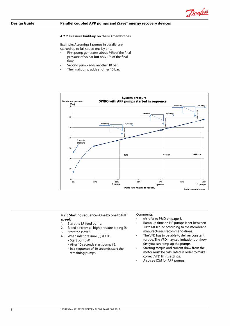
4.2.2 Pressure build-up on the RO membranes
Example: Assuming 3 pumps in parallel are started up to full speed one by one.• First pump generates about 74% of the final
pressure of 58 bar but only 1/3 of the final flow.
• Second pump adds another 10 bar.• The final pump adds another 10 bar.
4.2.3 Starting sequence - One by one to full speed:1. Start the LP feed pump.2. Bleed air from all high pressure piping (8).3. Start the iSave®.4. When inlet pressure (3) is OK: - Start pump #1. - After 10 seconds start pump #2. - In a sequence of 10 seconds start the remaining pumps.
Comments:• (#) refer to P&ID on page 3.• Ramp up time on HP pumps is set between
10 to 60 sec. or according to the membrane manufacturers recommendations.
• The VFD has to be able to deliver constant torque. The VFD may set limitations on how fast you can ramp up the pumps.
• Starting torque and current draw from the motor must be calculated in order to make correct VFD limit settings.
• Also see IOM for APP pumps.
SWRO with APP pumps started in sequence

Design Guide Parallel coupled APP pumps and iSave® energy recovery devices
9180R9354 / 521B1379 / D KCFN.PI.003.3A.02 / 09.2017
Starting sequence:1. Start the LP feed pump.2. Bleed air from all high pressure piping (8).3. Start the iSave®.4. When inlet pressure (3) is OK: -Start pump #1 and ramp up to 700 rpm. - Start pump #2 and ramp up to 700 rpm. - Start pump #3 and ramp up to 700 rpm. - Ramp up all three pumps to final speed.
Comments• (#) refer to P&ID on page 3.• Ramp up time on HP pumps is set between
10 to 60 sec. or according to the membrane manufacturers recommendations.
• By starting up the pumps in the above sequence the total starting current from the grid is reduced to a minimum.
• The VFD has to be able to deliver constant torque. The VFD may set limitations on how fast you can ramp up the pumps.
• Starting torque and current draw from the motor must be calculated in order to make correct VFD limit settings.
• Also see IOM for APP pumps.
4.2.4 Starting sequence - Two step ramp up
Example: Assuming 3 pumps in parallel started up to minimum speed one by one.• First pump generates 55% of the final pres-
sure of 58 bar - but only 17% of the final flow.
• Second pump adds another 6 bar.• The final pump adds another 6 bar.• Finally all 3 pumps are ramped up to full
speed.
SWRO with APP pumps started in sequence
4.2.5 Starting sequence - All pumps at the same time
1. Start the LP feed pump.2. Bleed air from high pressure piping (8).3. Start the iSave®.4. When the inlet pressure (3) is OK: - Start all pumps at the same time.
Comments:
• (#) refer to P&ID on page 3.• Ramp up time is set between 10 to 60 sec.
according to the membrane manufacturers recommendations.
• By starting up the pumps in the above sequence the starting current per motor is reduced to a minimum but the total current draw from the grid is the maximum.
• The VFD has to be able to deliver constant torque. The VFD may set limitations on how fast you can ramp up the pumps.
Design Guide Parallel coupled APP pumps and iSave® energy recovery devices
10 180R9354 / 521B1379 / DKCFN.PI.003.3A.02 / 09.2017
4.2.8 Stopping sequence
The main focus when stopping APP pumps in parallel is to prevent water-hammering in the inlet of the pumps. It is recommended to slowly ramp down the pumps. Either one by one or all at the same time.
Be aware of, if the pump is controlled by a soft starter, ramping down the speed cannot be done gently. The soft starter is ramping down the power to the motor and not the rpm.As the APP pump needs constant torque the pump will stop immediately when the power input becomes too low and potentially generates water hammer.
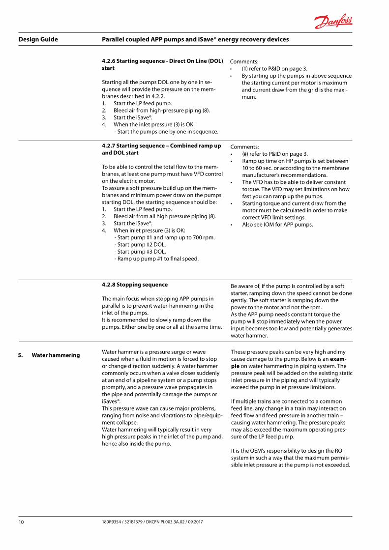
5. Water hammering Water hammer is a pressure surge or wave caused when a fluid in motion is forced to stop or change direction suddenly. A water hammer commonly occurs when a valve closes suddenly at an end of a pipeline system or a pump stops promptly, and a pressure wave propagates in the pipe and potentially damage the pumps or iSaves®. This pressure wave can cause major problems, ranging from noise and vibrations to pipe/equip-ment collapse. Water hammering will typically result in very high pressure peaks in the inlet of the pump and, hence also inside the pump.
These pressure peaks can be very high and my cause damage to the pump. Below is an exam-ple on water hammering in piping system. The pressure peak will be added on the existing static inlet pressure in the piping and will typically exceed the pump inlet pressure limitaions.
If multiple trains are connected to a common feed line, any change in a train may interact on feed flow and feed pressure in another train – causing water hammering. The pressure peaks may also exceed the maximum operating pres-sure of the LP feed pump.
It is the OEM’s responsibility to design the RO-system in such a way that the maximum permis-sible inlet pressure at the pump is not exceeded.
4.2.6 Starting sequence - Direct On Line (DOL) start
Starting all the pumps DOL one by one in se-quence will provide the pressure on the mem-branes described in 4.2.2.1. Start the LP feed pump.2. Bleed air from high-pressure piping (8).3. Start the iSave®.4. When the inlet pressure (3) is OK: - Start the pumps one by one in sequence.
4.2.7 Starting sequence – Combined ramp up and DOL start
To be able to control the total flow to the mem-branes, at least one pump must have VFD control on the electric motor.To assure a soft pressure build up on the mem-branes and minimum power draw on the pumps starting DOL, the starting sequence should be:1. Start the LP feed pump.2. Bleed air from all high pressure piping (8).3. Start the iSave®.4. When inlet pressure (3) is OK: - Start pump #1 and ramp up to 700 rpm. - Start pump #2 DOL. - Start pump #3 DOL. - Ramp up pump #1 to final speed.
Comments:• (#) refer to P&ID on page 3.• By starting up the pumps in above sequence
the starting current per motor is maximum and current draw from the grid is the maxi-mum.
Comments:• (#) refer to P&ID on page 3.• Ramp up time on HP pumps is set between
10 to 60 sec. or according to the membrane manufacturer’s recommendations.
• The VFD has to be able to deliver constant torque. The VFD may set limitations on how fast you can ramp up the pumps.
• Starting torque and current draw from the motor must be calculated in order to make correct VFD limit settings.
• Also see IOM for APP pumps.
Design Guide Parallel coupled APP pumps and iSave® energy recovery devices
11180R9354 / 521B1379 / D KCFN.PI.003.3A.02 / 09.2017
6. Sizing of electric motors and VFD
6.1 Sizing of electric motors and VFD for APP pump and iSave®The APP pump and iSave® are positive displace-ment machines:• The torque is proportional to the differ-
ence between inlet pressure and discharge pressure. This means that e.g. doubling the differential pressure requires double torque.
• At same differential pressure, the pump or iSave® requires same torque over the whole range of rpm - CONSTANT TORQUE.
• If the pump or iSave® starts against an existing pressure, the pump torque applies immediately as the pump starts to rotate and correspond to the existing differential pressure.
• The APP pump and iSave® have water lubri-cated bearings. These bearings generate a stick–slip torque at startup.
• To size the electric motor and VFD the starting torque generated by both stick-slip and discharge pressure must be taking into calculations - See next page.
• Both the electric motor and VFD must have sufficient power to start the Pump or iSave®. See IOM for APP pump and iSave®.
VFD needs to be able to deliver CONSTANT TORQUE and power enough to start the pump or iSave®.• It is recommended that both the electric
motor and VFD have a minimum 10% over-capacity on the ongoing operation torque.
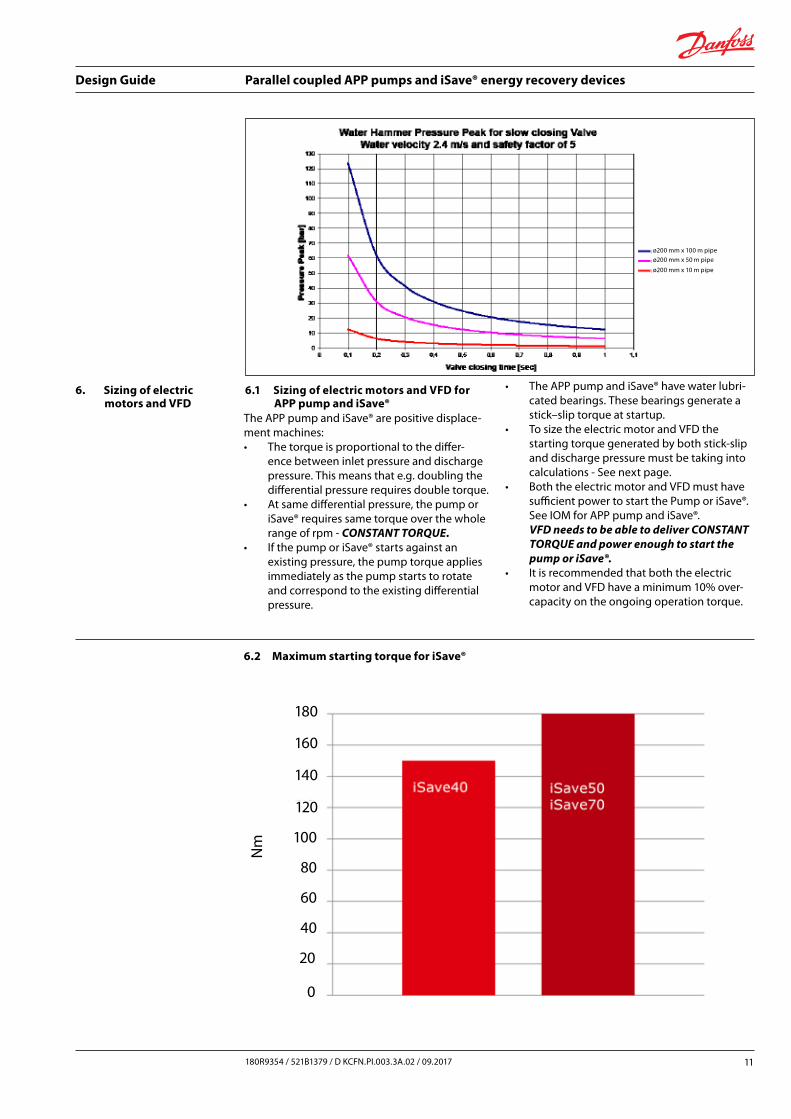
6.2 Maximum starting torque for iSave®
140
120
100
80
60
40
20
0
Nm
160
180
ø200 mm x 100 m pipe
ø200 mm x 50 m pipe
ø200 mm x 10 m pipe
Design Guide Parallel coupled APP pumps and iSave® energy recovery devices
12 180R9354 / 521B1379 / DKCFN.PI.003.3A.02 / 09.2017
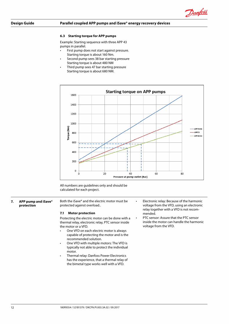
6.3 Starting torque for APP pumps
Example: Starting sequence with three APP 43 pumps in parallel.• First pump does not start against pressure.
Starting torque is about 160 Nm.• Second pump sees 38 bar starting pressure
Starting torque is about 480 NM• Third pump sees 47 bar starting pressure
Starting torque is about 680 NM.
All numbers are guidelines only and should be calculated for each project.
7. APP pump and iSave® protection
Both the iSave® and the electric motor must be protected against overload..
7.1 Motor protection
Protecting the electric motor can be done with a thermal relay, electronic relay, PTC sensor inside the motor or a VFD.• One VFD on each electric motor is always
capable of protecting the motor and is the recommended solution.
• One VFD with multiple motors: The VFD is typically not able to protect the individual motor.
• Thermal relay: Danfoss Power Electronics has the experience, that a thermal relay of the bimetal type works well with a VFD.
• Electronic relay: Because of the harmonic voltage from the VFD, using an electronic relay together with a VFD is not recom-mended.
• PTC sensor: Assure that the PTC sensor inside the motor can handle the harmonic voltage from the VFD.

Design Guide Parallel coupled APP pumps and iSave® energy recovery devices
13180R9354 / 521B1379 / D KCFN.PI.003.3A.02 / 09.2017
7.2 iSave® and APP pump protection
When protecting the pump and iSave® against overload both the maximum torque and maxi-mum pressure must be taken into account.• Maximum allowable operting pressure ac-
cording to IOM.• Maximum allowable operating torque ac-
cording to IOM. See principle requirements of load protection below.
• Using a thermal relay of the bimetal type: Calculating the current drawn by the elec- tric motor according to torque is possible. As the response time is much too slow, a thermal relay is many times NOT capable of protecting the APP pump or iSave®.• Using a VFD with a single motor: Follow the
guideline in the IOM.
Start up (Control of stick-slip):• Ramp up speed from 0 to set-point.• The starting torque must not exceed 140%
of max allowable working torque according to IOM.
Ongoing operating:• Continuously the torque must not exceed
120% of max. allowable working torque for more than 30 sec.
• The torque can periodically go up to 140% of max. allowable working torque as long as the time is no longer than 5 sec.
600 900
7.3 Multiple VFD versa single VFD control
Multiple motors operation is a common applica-tion. Using one VFD to control these multiple motors provides a host of advantages as summarized below.• Money is saved because one high horse-
power rated VFD is less expensive than multiple low horsepower VFDs. Each VFD requires its own circuit protection, so using one VFD reduces cost in this area as well.
• The VFD enclosure can be smaller because one large VFD requires less cabinet space than multiple smaller units. This saves space and money, complexity and design costs.
• Maintenance time and costs are cut because only one VFD has to be serviced as opposed to multiple smaller VFDs
• The overall control system also becomes much simpler. Instead of connecting many VFDs to the main controller, usually a PLC, and synchronizing their operations; only one connection is required. When program-ming the PLC, only one VFD speed control loop needs to be configured, instead of multiple instances.
Load protection
160%
140%
120%
100%
80%
60%
40%
20%
0%
loads
Max. starting load (Nm)
Max. load 120% Nm
30 sec. 30 sec.
0 150 300 450 750 1050 1200 1200 1200 1200
load
load
max. load
rpm
Design Guide Parallel coupled APP pumps and iSave® energy recovery devices
14 180R9354 / 521B1379 / DKCFN.PI.003.3A.02 / 09.2017
But even given these benefits, most VFD instal-lations with multiple motors use one VFD per motor. Why is that?• The VFD becomes a single point of failure,
motor and connected load reliability actu-ally improve in many applications as there are now multiple smaller motors as opposed to one large motor. If one motor fails, it is often possible to continue operation with the remaining motors.
• To minimize VFD size, all motors need to be started up simultaneously. The VFD will ramp all the motors up to speed at a con-trolled rate, minimizing the starting current required by each motor at startup.
• EACH motor must be individually protected, considering the load, speed, torque, etc.
• As the pump driven by the motor can often handle less load than the motor, EACH pump must be protected considering the torque. This can be done by using a VFD on each motor.
• A VFD only senses its total connected load, outputting as many amps as needed up to its current rating. When controlling multiple motors, a single VFD cannot sense which motor is drawing high current, so it cannot provide appropriate overload and over current protection to each individual motor and pump.
This is why each individual motor must have its own short circuit and overload protection.
Using one VFD with multiple motors:• A single VFD on each motor is often same
price or less than a monitoring relay solution capable of handling the harmonic from the VFD and one large common VFD. Calcula-tions must be made case by case.
• With the experience Danfoss Power Electronics has today, protecting the individual iSave® running on a common VFD is complicated and expensive.
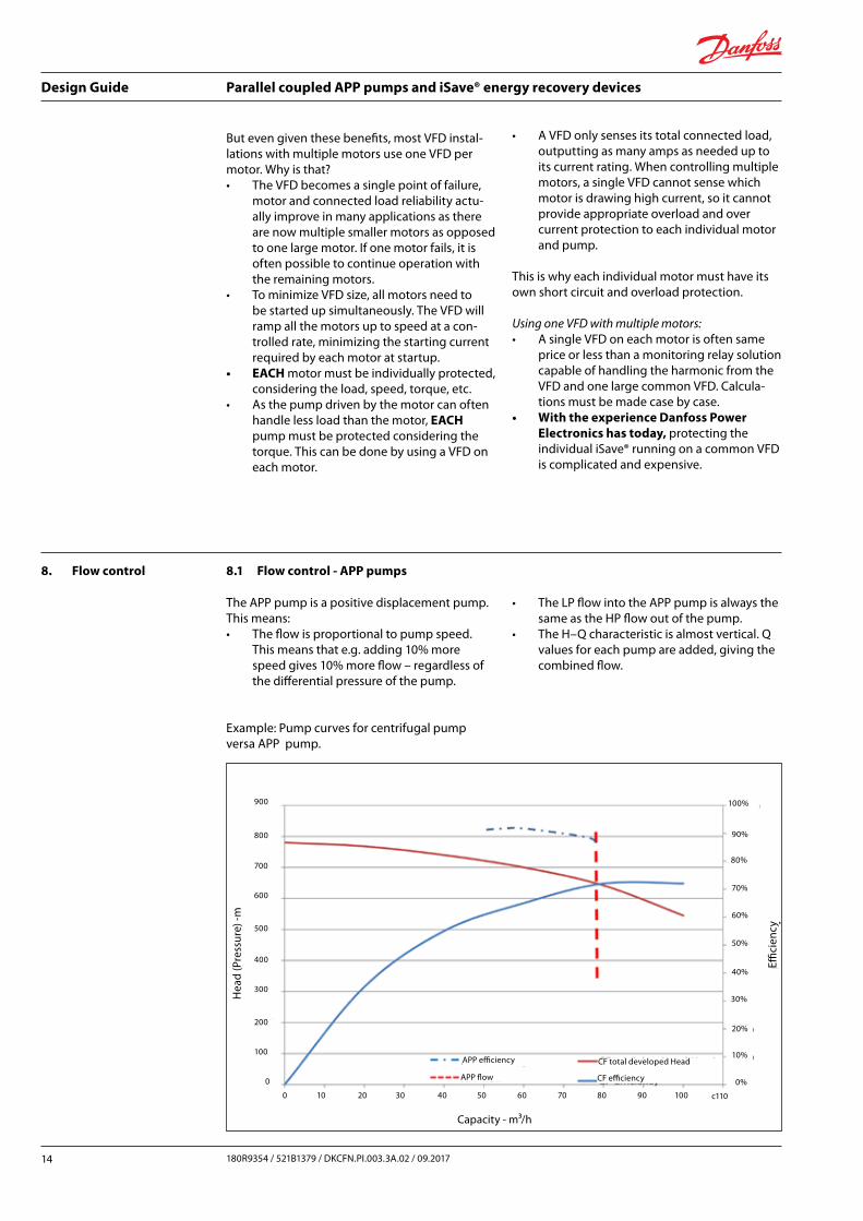
8. Flow control 8.1 Flow control - APP pumps
The APP pump is a positive displacement pump. This means:• The flow is proportional to pump speed.
This means that e.g. adding 10% more speed gives 10% more flow – regardless of the differential pressure of the pump.
Example: Pump curves for centrifugal pump versa APP pump.
• The LP flow into the APP pump is always the same as the HP flow out of the pump.
• The H–Q characteristic is almost vertical. Q values for each pump are added, giving the combined flow.
Effici
ency
Hea
d (P
ress
ure)
-m
Capacity - m³/h
900
800
700
600
500
400
300
200
100
0
80%
70%
60%
90%
100%
50%
40%
30%
20%
10%
0%
0 10 20 30 40 50 60 70 80 90 100 c110
APP efficiency
APP flow
CF total developed Head
CF efficiency

Design Guide Parallel coupled APP pumps and iSave® energy recovery devices
15180R9354 / 521B1379 / D KCFN.PI.003.3A.02 / 09.2017
8.2 Flow control - iSaves®
8.2.1 High pressure circulation flow
The vane pump in the iSave® is a positive dis-placement pump. This means:• The iSave® HP-flow is proportional to iSave®
speed. This means that e.g. adding 10% more speed gives 10% more flow – regard-less of the differential pressure of the iSave®.
• The H–Q characteristic is almost vertical. Q values for each iSave® are added, giving the combined flow.
8.2.2 LP flushing flow
The flow through the LP side on the iSave® is controlled by the pressure difference between LP
in and LP
out. If the pressure drops are equal the
flows are equal.• The pressure difference changes with the
speed of the iSave®.• When running multiple iSaves® in parallel it
is recommended that all iSaves® are running at the same speed.
9. Noise level 9.1 Noise level with multiple sources
If multiple acoustic sources are running next by each other the total sound level (pressure) of all sources is higher than the sound level for each source.
Example: Below graph shows the combined sound level for multiple iSaves® or pumps each making 85 dB.
10. Disclaimer Although the information and recommendations in this document (electronic or printed form) are presented in good faith and believed to be cor-rect, Danfoss A/S, Danfoss High Pressure Pumps makes no representations or warranties as to the completeness or accuracy of the information.Information is supplied upon the condition that the persons receiving same will make their own determination as to its suitability for their pur-poses prior to use. In no event will Danfoss A/S, Danfoss High Pressure Pumps be responsible for damages of any nature whatsoever resulting from the use of or reliance upon information
from this document or the products to which the information refers. Danfoss A/S,Danfoss High Pressure Pumps does not warrant the accuracy or timeliness of the materials in the document and has no liability for any errors or omissions in the materials.THIS “DOCUMENT” IS PROVIDED ON AN “AS IS” BASIS. NO REPRESENTATIONS OR WARRANTIES, EITHER EXPRESSED OR IMPLIED, OF MERCHANT-ABILITY, FITNESS FOR A PARTICULAR PURPOSE OR OF ANY OTHER NATURE ARE MADE HEREUNDER WITH RESPECT TO INFORMATION OR THE PRO-DUCTS TO WHICH INFORMATION REFERS

© Danfoss | DCS (im) | 2017.09 180R9354 | 521B1379 | D KCFN.PI.003.3A.02 | 16
Danfoss can accept no responsibility for possible errors in catalogues, brochures and other printed material. Danfoss reserves the right to alter its products without notice. This also applies to products already on order provided that such alterations can be made without subsequential changes being necessary in specifications already agreed.All trademarks in this material are property of the respective companies. Danfoss and the Danfoss logotype are trademarks of Danfoss A/S. All rights reserved.
Danfoss A/SHigh Pressure PumpsDK-6430 NordborgDenmark