Embed Size (px)
Citation preview

MAKING MODERN LIVING POSSIBLE
Design GuideVLT® HVAC Basic Drive
Contents
1 How to Read this Design Guide 3
1.1.1 Copyright, Limitation of Liability and Revision Rights 3
1.1.3 Symbols 4
1.1.4 Abbreviations 4
1.1.5 Definitions 5
2 Introduction to VLT HVAC Basic Drive 8
2.1 Safety 8
2.2 CE Labelling 9
2.3.1 Aggressive Environments 10
2.4 Vibration and Shock 10
2.6 Control Structures 23
2.7 General Aspects of EMC 30
2.7.3 EMC Test Results 32
2.8 Galvanic Isolation (PELV) 34
2.8.1 PELV - Protective Extra Low Voltage 34
2.9 Earth Leakage Current 34
2.10 Extreme Running Conditions 35
3 VLT HVAC Basic Drive Selection 37
3.1 Options and Accessories 37
3.1.1 Local Control Panel (LCP) 37
3.1.2 Mounting of LCP in Panel Front 37
3.1.4 Decoupling Plate 40
4 How to Order 41
4.1.2 Type Code String 42
5 How to Install 45
5.1.1 Side-by-Side Installation 46
5.2 Electrical Data 47
5.2.1 Electrical Overview 47
5.2.2 Electrical Installation in General 48
5.2.3 Connecting to Mains and Motor 49
5.2.4 Fuses 50
5.2.5 EMC-Correct Electrical Installation 51
5.2.6 Control Terminals 53
6 How to Programme 54
6.1 Programming with MCT 10 Set-up Software 54
6.2 Local Control Panel (LCP) 54
Contents VLT HVAC Basic Drive Design Guide
MG.18.C2.02 - VLT® is a registered Danfoss trademark 1

6.3 Menus 55
6.3.1 Status 55
6.3.2 Quick Menu 55
6.3.3 The FC 101 Start-up Wizard for Open Loop Applications 55
6.3.4 Main Menu 61
6.4 Quick Transfer of Parameter Settings between Multiple Frequency Converters 62
6.5 Read-out and Programming of Indexed Parameters 62
6.6 Initialise the Frequency Converter to Default Settings in two Ways 62
7 RS-485 Installation and Set-up 64
7.2 FC Protocol Overview 65
7.3 Network Configuration 66
7.4 FC Protocol Message Framing Structure 66
7.5 Examples 69
7.6 Modbus RTU Overview 69
7.8 Modbus RTU Message Framing Structure 70
7.9 How to Access Parameters 74
7.10 Examples 75
7.11 Danfoss FC Control Profile 77
8 General Specifications and Troubleshooting 81
8.1 Mains Supply Tables 81
8.1.1 Mains Supply 3 x 200-240V AC 81
8.1.2 Mains Supply 3 x 380-480VAC 82
8.1.3 Mains Supply 3 x 380-480VAC 84
8.1.4 Mains Supply 3 x 525-600VAC 85
8.2 General Specifications 86
8.3 Acoustic Noise 88
Index 89
Contents VLT HVAC Basic Drive Design Guide
2 MG.18.C2.02 - VLT® is a registered Danfoss trademark
1 How to Read this Design Guide
VLT HVAC Basic DriveFC 100 Series
Software version: 1.4X
This guide can be used with all VLTHVAC Basic Drive frequency
converters with software version1.4X.
The actual software versionnumber can be read from
15-43 Software Version.
1.1.1 Copyright, Limitation of Liability andRevision Rights
This publication contains information proprietary toDanfoss. By accepting and using this manual the useragrees that the information contained herein will be usedsolely for operating equipment from Danfoss or equipmentfrom other vendors provided that such equipment isintended for communication with Danfoss equipment overa serial communication link. This publication is protectedunder the Copyright laws of Denmark and most othercountries.
Danfoss does not warrant that a software programproduced according to the guidelines provided in thismanual will function properly in every physical, hardwareor software environment.
Although Danfoss has tested and reviewed the documen-tation within this manual, Danfoss makes no warranty orrepresentation, neither expressed nor implied, with respectto this documentation, including its quality, performance,or fitness for a particular purpose.
In no event shall Danfoss be liable for direct, indirect,special, incidental, or consequential damages arising out ofthe use, or the inability to use information contained inthis manual, even if advised of the possibility of suchdamages. In particular, Danfoss is not responsible for anycosts, including but not limited to those incurred as aresult of lost profits or revenue, loss or damage ofequipment, loss of computer programs, loss of data, thecosts to substitute these, or any claims by third parties.
Danfoss reserves the right to revise this publication at anytime and to make changes to its contents without priornotice or any obligation to notify former or present usersof such revisions or changes.
1.1.2 Available Literature for VLT HVACBasic Drive
- Quick Guide MG.18.AX.YY
- Programming Guide MG.18.BX.YY providesinformation on how to programme and includescomplete parameter descriptions.
- Design Guide MG.18.Cx.yy entails all technicalinformation about the frequency converter andcustomer design and applications.
- PC-based Configuration Tool MCT 10, MG.10.AX.YY enables the user to configure the
How to Read this Design Gui... VLT HVAC Basic Drive Design Guide
MG.18.C2.02 - VLT® is a registered Danfoss trademark 3
1 1

frequency converter from a Windows™ based PCenvironment.
- Danfoss VLT® Energy Box software atwww.danfoss.com/BusinessAreas/DrivesSolutionsthen choose PC Software DownloadVLT® Energy Box Software allows energyconsumption comparisons of HVAC fans andpumps driven by Danfoss drives and alternativemethods of flow control. This tool may be usedto project, as accurately as possible, the costs,savings, and payback of using Danfoss frequencyconverters on HVAC fans and pumps.
x = Revision numberyy = Language code
Danfoss technical literature is available in print from yourlocal Danfoss Sales Office or online at: www.danfoss.com/BusinessAreas/DrivesSolutions/Documen-tations/Technical+Documentation.htm
1.1.3 Symbols
Symbols used in this guide.
NOTEIndicates something to be noted by the reader.
CAUTIONIndicates a potentially hazardous situation which, if notavoided, may result in minor or moderate injury orequipment damage.
WARNINGIndicates a potentially hazardous situation which, if notavoided, could result in death or serious injury.
* Indicates default setting
1.1.4 Abbreviations
Alternating current AC
American wire gauge AWG
Ampere/AMP A
Automatic Motor Adaptation AMA
Current limit ILIM
Degrees Celsius °CDirect current DC
Electro Magnetic Compatibility EMC
Electronic Thermal Relay ETR
Frequency Converter FC
Gram g
Hertz Hz
Kilohertz kHz
Local Control Panel LCP
Meter m
Millihenry Inductance mH
Milliampere mA
Millisecond ms
Minute min
Motion Control Tool MCT
Nanofarad nF
Newton Meters Nm
Nominal motor current IM,N
Nominal motor frequency fM,N
Nominal motor power PM,N
Nominal motor voltage UM,N
Parameter par.
Protective Extra Low Voltage PELV
Printed Circuit Board PCB
Rated Inverter Output Current IINV
Revolutions Per Minute RPM
Regenerative terminals Regen
Second sec.
Synchronous Motor Speed ns
Torque limit TLIM
Volts V
The maximum output current IVLT,MAX
The rated output current supplied by thefrequency converter
IVLT,N
How to Read this Design Gui... VLT HVAC Basic Drive Design Guide
4 MG.18.C2.02 - VLT® is a registered Danfoss trademark
11

1.1.5 Definitions
Frequency converter
IVLT,MAX
The maximum output current.
IVLT,N
The rated output current supplied by the frequencyconverter.
UVLT, MAX
The maximum output voltage.
Input
Control commandYou can start and stop theconnected motor by meansof LCP and the digitalinputs.Functions are divided into 2groups.Functions in group 1 havehigher priority thanfunctions in group 2.
Group1
Reset, Coasting stop,Reset and Coasting stop,Quick-stop, DC braking,Stop and the [Off] key.
Group2
Start, Pulse start,Reversing, Start reversing,Jog and Freeze output
Motor
fJOG
The motor frequency when the jog function is activated(via digital terminals).
fM
The motor frequency.
fMAX
The maximum motor frequency.
fMIN
The minimum motor frequency.
fM,N
The rated motor frequency (nameplate data).
IM
The motor current.
IM,N
The rated motor current (nameplate data).
nM,N
The rated motor speed (nameplate data).
PM,N
The rated motor power (nameplate data).
UM
The instantaneous motor voltage.
UM,N
The rated motor voltage (nameplate data).
Break-away torque
175Z
A07
8.10
Pull-out
rpm
Torque
ηVLT
The efficiency of the LCP is defined as the ratio betweenthe power output and the power input.
Start-disable commandA stop command belonging to the group 1 controlcommands - see this group.
Stop commandSee Control commands.
References
Analog ReferenceA signal transmitted to the analog inputs 53 or 54, can bevoltage or current.
Bus ReferenceA signal transmitted to the serial communication port (FCport).
Preset ReferenceA defined preset reference to be set from -100% to +100%of the reference range. Selection of eight preset referencesvia the digital terminals.
How to Read this Design Gui... VLT HVAC Basic Drive Design Guide
MG.18.C2.02 - VLT® is a registered Danfoss trademark 5
1 1

RefMAX
Determines the relationship between the reference inputat 100% full scale value (typically 10V, 20mA) and theresulting reference. The maximum reference value set in3-03 Maximum Reference.
RefMIN
Determines the relationship between the reference inputat 0% value (typically 0V, 0mA, 4mA) and the resultingreference. The minimum reference value set in3-02 Minimum Reference
MiscellaneousAnalog InputsThe analog inputs are used for controlling variousfunctions of the frequency converter.There are two types of analog inputs:Current input, 0-20mA and 4-20mAVoltage input, 0-10V DC.
Analog OutputsThe analog outputs can supply a signal of 0-20mA,4-20mA, or a digital signal.
Automatic Motor Adaptation, AMAAMA algorithm determines the electrical parameters forthe connected motor at standstill.
Digital InputsThe digital inputs can be used for controlling variousfunctions of the frequency converter.
Digital OutputsThe frequency converter features 2 Solid State outputs thatcan supply a 24V DC (max. 40mA) signal.
Relay OutputsThe frequency converter features two programmable RelayOutputs.
ETRElectronic Thermal Relay is a thermal load calculationbased on present load and time. Its purpose is to estimatethe motor temperature.
InitialisingIf initialising is carried out (14-22 Operation Mode), theprogrammable parameters of the frequency converterreturn to their default settings.Initialising; 14-22 Operation Mode will not initialisecommunication parameters.
Intermittent Duty CycleAn intermittent duty rating refers to a sequence of dutycycles. Each cycle consists of an on-load and an off-loadperiod. The operation can be either periodic duty or none-periodic duty.
LCP The Local Control Panel (LCP) makes up a completeinterface for control and programming of the frequencyconverter. The control panel is detachable and can beinstalled up to 3m from the frfrequency converter, i.e. in afront panel by means of the installation kit option.
lsbLeast significant bit.
MCMShort for Mille Circular Mil, an American measuring unit forcable cross-section. 1 MCM ≡ 0.5067mm2.
msbMost significant bit.
On-line/Off-line ParametersChanges to on-line parameters are activated immediatelyafter the data value is changed. Changes to off-lineparameters are not activated until you enter [OK] on theLCP.
PI ControllerThe PI controller maintains the desired speed, pressure,temperature, etc. by adjusting the output frequency tomatch the varying load.
RCDResidual Current Device.
Set-upYou can save parameter settings in 2 Set-ups. Changebetween the 2 parameter Set-ups and edit one Set-up,while another Set-up is active.
Slip CompensationThe frequency converter compensates for the motor slipby giving the frequency a supplement that follows themeasured motor load keeping the motor speed almostconstant.
Smart Logic Control (SLC)The SLC is a sequence of user defined actions executedwhen the associated user defined events are evaluated astrue by the SLC.
ThermistorA temperature-dependent resistor placed where thetemperature is to be monitored (frequency converter ormotor).
TripA state entered in fault situations, e.g. if the frequencyconverter is subject to an over-temperature or when thefrequency converter is protecting the motor, process ormechanism. Restart is prevented until the cause of thefault has disappeared and the trip state is cancelled byactivating reset or, in some cases, by being programmedto reset automatically. Trip may not be used for personalsafety.
How to Read this Design Gui... VLT HVAC Basic Drive Design Guide
6 MG.18.C2.02 - VLT® is a registered Danfoss trademark
11

Trip LockedA state entered in fault situations when the frequencyconverter is protecting itself and requiring physicalintervention, e.g. if the frequency converter is subject to ashort circuit on the output. A locked trip can only becancelled by cutting off mains, removing the cause of thefault, and reconnecting the frequency converter. Restart isprevented until the trip state is cancelled by activatingreset or, in some cases, by being programmed to resetautomatically. Trip locked may not be used for personalsafety.
VT CharacteristicsVariable torque characteristics used for pumps and fans.
VVCplus
If compared with standard voltage/frequency ratio control,Voltage Vector Control (VVCplus) improves the dynamicsand the stability, both when the speed reference ischanged and in relation to the load torque.
1.1.6 Power Factor
The power factor is the relation between I1 and IRMS.
Power factor =3 × U × I1 × COSϕ
3 × U × IRMSThe power factor for 3-phase control:
=I1 × cosϕ1
IRMS=
I1IRMS
since cosϕ1 = 1
The power factor indicates to which extent the frequencyconverter imposes a load on the mains supply.The lower the power factor, the higher the IRMS for thesame kW performance.
IRMS = I12 + I5
2 + I72 + . . + In
2
In addition, a high power factor indicates that the differentharmonic currents are low.The frequency converters' built-in DC coils produce a highpower factor, which minimizes the imposed load on themains supply.
How to Read this Design Gui... VLT HVAC Basic Drive Design Guide
MG.18.C2.02 - VLT® is a registered Danfoss trademark 7
1 1

2 Introduction to VLT HVAC Basic Drive
2.1 Safety
2.1.1 Safety Note
WARNINGDANGEROUS VOLTAGEThe voltage of the frequency converter is dangerouswhenever connected to mains. Incorrect installation of themotor, frequency converter or fieldbus may cause death,serious personal injury or damage to the equipment.Consequently, the instructions in this manual, as well asnational and local rules and safety regulations, must becomplied with.
Safety Regulations1. The frequency converter must be disconnected
from mains if repair work is to be carried out.Check that the mains supply has been discon-nected and that the necessary time has passedbefore removing motor and mains plugs.
2. The [STOP/RESET] key on the LCP of thefrequency converter does not disconnect theequipment from mains and is thus not to be usedas a safety switch.
3. Correct protective earthing of the equipmentmust be established, the user must be protectedagainst supply voltage, and the motor must beprotected against overload in accordance withapplicable national and local regulations.
4. The earth leakage currents are higher than3.5mA.
5. Protection against motor overload is set by1-90 Motor Thermal Protection. If this function isdesired, set 1-90 Motor Thermal Protection to datavalue [ETR trip] (default value) or data value [ETRwarning]. Note: The function is initialized at 1.16x rated motor current and rated motor frequency.For the North American market: The ETRfunctions provide class 20 motor overloadprotection in accordance with NEC.
6. Do not remove the plugs for the motor andmains supply while the frequency converter isconnected to mains. Check that the mains supplyhas been disconnected and that the necessarytime has passed before removing motor andmains plugs.
7. Check that all voltage inputs have been discon-nected and that the necessary time has passedbefore commencing repair work.
Installation at high altitudes
CAUTIONAt altitudes above 2km, please contact Danfoss regardingPELV.
WARNINGUNINTENDED START
1. The motor can be brought to a stop by means ofdigital commands, bus commands, references ora local stop, while the frequency converter isconnected to mains. If personal safety consider-ations make it necessary to ensure that nounintended start occurs, these stop functions arenot sufficient.
2. While parameters are being changed, the motormay start. Consequently, the stop key [STOP/RESET] must always be activated; following whichdata can be modified.
3. A motor that has been stopped may start if faultsoccur in the electronics of the frequencyconverter, or if a temporary overload or a fault inthe supply mains or the motor connection ceases.
WARNINGDISCHARGE TIMETouching the electrical parts may be fatal - even after theequipment has been disconnected from mains.Also make sure that other voltage inputs have beendisconnected, load sharing (linkage of DC intermediatecircuit), as well as the motor connection for kinetic backup.The frequency converter DC link capacitors remain chargedafter power has been disconnected. To avoid an electricalshock hazard, disconnect the frequency converter from themains before carrying out maintenance. Wait at least asfollows before doing service on the frequency converter:
Voltage (V) Power range (kW) Min. waiting time (min.)
3 x 200 0.25 – 3.7 4
3 x 200 5.5 – 45 15
3 x 400 0.37 – 7.5 4
3 x 400 11 – 90 15
3 x 600 2.2 – 7.5 4
3 x 600 11 – 90 15
Introduction to VLT HVAC Ba... VLT HVAC Basic Drive Design Guide
8 MG.18.C2.02 - VLT® is a registered Danfoss trademark
22

2.1.2 Disposal Instruction
Equipment containing electricalcomponents may not be disposed oftogether with domestic waste.It must be separately collected withelectrical and electronic waste accordingto local and currently valid legislation.
2.2 CE Labelling
2.2.1 CE conformity and labelling
What is CE Conformity and Labelling?The purpose of CE labelling is to avoid technical tradeobstacles within EFTA and the EU. The EU has introducedthe CE label as a simple way of showing whether aproduct complies with the relevant EU directives. The CElabel says nothing about the specifications or quality ofthe product. Frequency converters are regulated by threeEU directives:The machinery directive (98/37/EEC)All machines with critical moving parts are covered by themachinery directive of January 1, 1995. Since a frequencyconverter is largely electrical, it does not fall under themachinery directive. However, if a frequency converter issupplied for use in a machine, we provide information onsafety aspects relating to the frequency converter. We dothis by means of a manufacturer's declaration.The low-voltage directive (73/23/EEC)Frequency converters must be CE labelled in accordancewith the low-voltage directive of January 1, 1997. Thedirective applies to all electrical equipment and appliancesused in the 50 - 1000V AC and the 75 - 1500V DC voltageranges. Danfoss CE-labels in accordance with the directiveand issues a declaration of conformity upon request.The EMC directive (89/336/EEC)EMC is short for electromagnetic compatibility. Thepresence of electromagnetic compatibility means that themutual interference between different components/appliances does not affect the way the appliances work.The EMC directive came into effect January 1, 1996.Danfoss CE-labels in accordance with the directive andissues a declaration of conformity upon request. To carryout EMC-correct installation, see the instructions in thisDesign Guide. In addition, we specify which standards ourproducts comply with. We offer the filters presented in thespecifications and provide other types of assistance toensure the optimum EMC result.
The frequency converter is most often used by profes-sionals of the trade as a complex component forming partof a larger appliance, system or installation. It must benoted that the responsibility for the final EMC properties ofthe appliance, system or installation rests with the installer.
2.2.2 What is Covered
The EU "Guidelines on the Application of Council Directive89/336/EEC" outline three typical situations of using afrequency converter. See below for EMC coverage and CElabelling.
1. The frequency converter is sold directly to theend-consumer. The frequency converter is forexample sold to a DIY market. The end-consumeris a layman. He installs the frequency converterhimself for use with a hobby machine, a kitchenappliance, etc. For such applications, thefrequency converter must be CE labelled inaccordance with the EMC directive.
2. The frequency converter is sold for installation ina plant. The plant is built up by professionals ofthe trade. It could be a production plant or aheating/ventilation plant designed and installedby professionals of the trade. Neither thefrequency converter nor the finished plant has tobe CE labelled under the EMC directive. However,the unit must comply with the basic EMCrequirements of the directive. This is ensured byusing components, appliances, and systems thatare CE labelled under the EMC directive.
3. The frequency converter is sold as part of acomplete system. The system is being marketedas complete and could e.g. be an air-conditioningsystem. The complete system must be CE labelledin accordance with the EMC directive. Themanufacturer can ensure CE labelling under theEMC directive either by using CE labelledcomponents or by testing the EMC of the system.If he chooses to use only CE labelledcomponents, he does not have to test the entiresystem.
2.2.3 Danfoss Frequency Converter and CELabelling
CE labelling is a positive feature when used for its originalpurpose, i.e. to facilitate trade within the EU and EFTA.
However, CE labelling may cover many different specifi-cations. Thus, you have to check what a given CE labelspecifically covers.
The covered specifications can be very different and a CElabel may therefore give the installer a false feeling ofsecurity when using a frequency converter as a componentin a system or an appliance.
Danfoss CE labels the frequency converters in accordancewith the low-voltage directive. This means that if the
Introduction to VLT HVAC Ba... VLT HVAC Basic Drive Design Guide
MG.18.C2.02 - VLT® is a registered Danfoss trademark 9
2 2

frequency converter is installed correctly, we guaranteecompliance with the low-voltage directive. Danfoss issues adeclaration of conformity that confirms our CE labelling inaccordance with the low-voltage directive.
The CE label also applies to the EMC directive providedthat the instructions for EMC-correct installation andfiltering are followed. On this basis, a declaration ofconformity in accordance with the EMC directive is issued.
The Design Guide offers detailed instructions for instal-lation to ensure EMC-correct installation. Furthermore,Danfoss specifies which our different products complywith.
Danfoss provides other types of assistance that can helpyou obtain the best EMC result.
2.2.4 Compliance with EMC Directive89/336/EEC
As mentioned, the frequency converter is mostly used byprofessionals of the trade as a complex componentforming part of a larger appliance, system, or installation. Itmust be noted that the responsibility for the final EMCproperties of the appliance, system or installation restswith the installer. As an aid to the installer, Danfoss hasprepared EMC installation guidelines for the Power Drivesystem. The standards and test levels stated for PowerDrive systems are complied with, provided that the EMC-correct instructions for installation are followed, see thesection EMC Immunity.
The frequency converter has been designed to meet theIEC/EN 60068-2-3 standard, EN 50178 pkt. 9.4.2.2 at 50°C.
2.3.1 Aggressive Environments
A frequency converter contains a large number ofmechanical and electronic components. All are to someextent vulnerable to environmental effects.
CAUTIONThe frequency converter should not be installed inenvironments with airborne liquids, particles, or gasescapable of affecting and damaging the electroniccomponents. Failure to take the necessary protectivemeasures increases the risk of stoppages, thus reducingthe life of the frequency converter.
Liquids can be carried through the air and condense in thefrequency converter and may cause corrosion ofcomponents and metal parts. Steam, oil, and salt watermay cause corrosion of components and metal parts. Insuch environments, use equipment with enclosure ratingIP54. As an extra protection, coated printed circuit boards
can be ordered as an option.(Standard on some powersizes.)
Airborne Particles such as dust may cause mechanical,electrical, or thermal failure in the frequency converter. Atypical indicator of excessive levels of airborne particles isdust particles around the frequency converter fan. In verydusty environments, use equipment with enclosure ratingIP54 or a cabinet for IP20/TYPE 1 equipment.
In environments with high temperatures and humidity,corrosive gases such as sulphur, nitrogen, and chlorinecompounds will cause chemical processes on thefrequency converter components.
Such chemical reactions will rapidly affect and damage theelectronic components. In such environments, mount theequipment in a cabinet with fresh air ventilation, keepingaggressive gases away from the frequency converter.An extra protection in such areas is a coating of theprinted circuit boards, which can be ordered as an option.
NOTEMounting frequency converters in aggressive environmentsincreases the risk of stoppages and considerably reducesthe life of the converter.
Before installing the frequency converter, check theambient air for liquids, particles, and gases. This is done byobserving existing installations in this environment. Typicalindicators of harmful airborne liquids are water or oil onmetal parts, or corrosion of metal parts.
Excessive dust particle levels are often found on instal-lation cabinets and existing electrical installations. Oneindicator of aggressive airborne gases is blackening ofcopper rails and cable ends on existing installations.
2.4 Vibration and Shock
The frequency converter has been tested according to theprocedure based on the shown standards:
The frequency converter complies with requirements thatexist for units mounted on the walls and floors ofproduction premises, as well as in panels bolted to walls orfloors.
IEC/EN 60068-2-6: Vibration (sinusoidal) - 1970
IEC/EN 60068-2-64: Vibration, broad-band random
Introduction to VLT HVAC Ba... VLT HVAC Basic Drive Design Guide
10 MG.18.C2.02 - VLT® is a registered Danfoss trademark
22

2.5 Advantages
2.5.1 Why use a Frequency Converter forControlling Fans and Pumps?
A frequency converter takes advantage of the fact thatcentrifugal fans and pumps follow the laws of propor-tionality for such fans and pumps. For further informationsee 2.4.3 Example of Energy Savings.
2.5.2 The Clear Advantage - Energy Savings
The very clear advantage of using a frequency converterfor controlling the speed of fans or pumps lies in theelectricity savings.When comparing with alternative control systems andtechnologies, a frequency converter is the optimum energycontrol system for controlling fan and pump systems.
SYSTEM CURVE
FAN CURVE
PRES
SURE
%
130B
A78
0.10
A
B
C
0
20
40
60
80
100
120
20 40 60 80 100 120 140 160 180VOLUME%
Illustration 2.1 The graph is showing fan curves (A, B and C) forreduced fan volumes.
120
100
80
60
40
20
0 20 40 60 80 100 120 140 160 180
120
100
80
60
40
20
0 20 40 60 80 100 120 140 160 180
Voume %
Voume %
INPU
T PO
WER
%PR
ESSU
RE %
SYSTEM CURVE
FAN CURVE
A
B
C
130B
A78
1.10
ENERGYCONSUMED
Illustration 2.2 When using a frequency converter to reduce fancapacity to 60% - more than 50% energy savings may beobtained in typical applications.
2.5.3 Example of Energy Savings
As shown in Illustration 2.3, the flow is controlled bychanging the RPM. By reducing the speed only 20% fromthe rated speed, the flow is also reduced by 20%. This isbecause the flow is directly proportional to the RPM. Theconsumption of electricity, however, is reduced by 50%.If the system in question only needs to be able to supply aflow that corresponds to 100% a few days in a year, whilethe average is below 80% of the rated flow for theremainder of the year, the amount of energy saved is evenmore than 50%.
The laws of proportionality
Illustration 2.3 describes the dependence of flow, pressure andpower consumption on RPM.
Q = Flow P = Power
Q1 = Rated flow P1 = Rated power
Q2 = Reduced flow P2 = Reduced power
H = Pressure n = Speed regulation
H1 = Rated pressure n1 = Rated speed
H2 = Reduced
pressure
n2 = Reduced speed
Introduction to VLT HVAC Ba... VLT HVAC Basic Drive Design Guide
MG.18.C2.02 - VLT® is a registered Danfoss trademark 11
2 2

n
100%
50%
25%
12,5%
50% 100%
80%
80%17
5HA
208.
10
Power ~n 3
Pressure ~n 2
Flow ~n
Illustration 2.3 Laws of Proportionally
Flow :Q1Q2
= n1n2
Pressure :H1H2
= ( n1n2 )2
Power :P1P2
= ( n1n2 )3
2.5.4 Comparison of Energy Savings
The Danfoss frequency converter solution offers majorsavings compared with traditional energy saving solutions.This is because the frequency converter is able to controlfan speed according to thermal load on the system andthe fact that the frequency converter has a built-in facilitythat enables the frequency converter to function as aBuilding Management System, BMS.
Illustration 2.5 shows typical energy savings obtainablewith 3 well-known solutions when fan volume is reducedto i.e. 60%.As the graph shows, more than 50% energy savings can beachieved in typical applications.
130B
A78
2.10
Dischargedamper
Less energy savings
IGV
Costlier installation
Maximum energy savings
Illustration 2.4 The Three Common Energy Saving Systems
130B
A77
9.11
0 60 0 60 0 600
20
40
60
80
100
Discharge Damper Solution
IGV Solution
VLT Solution
Ener
gy c
onsu
med
Ener
gy c
onsu
med
Ener
gy c
onsu
med
Inpu
t pow
er %
Volume %
Illustration 2.5 Energy Savings
Discharge dampers reduce power consumption somewhat.Inlet Guide Vans offer a 40% reduction but are expensiveto install. The Danfoss frequency converter solutionreduces energy consumption with more than 50% and iseasy to install.
Introduction to VLT HVAC Ba... VLT HVAC Basic Drive Design Guide
12 MG.18.C2.02 - VLT® is a registered Danfoss trademark
22

2.5.5 Example with Varying Flow over 1Year
The example below is calculated on the basis of pumpcharacteristics obtained from a pump datasheet.The result obtained shows energy savings in excess of 50%at the given flow distribution over a year. The pay backperiod depends on the price per kWh and price offrequency converter. In this example it is less than a yearwhen compared with valves and constant speed.
Energy savingsPshaft=Pshaft output
Flow distribution over 1 year17
5HA
209.
11
60
50
40
30
20
10
Hs
0 100 200 300 400
(mwg)
B
C
A
750rpm
1050rpm
1350rpm
1650rpm
0
10
20
30
(kW)
40
50
60
200100 300 (m3 /h)
(m3 /h)
400
750rpm
1050rpm
1350rpm
1650rpm
Pshaft
C1
B1
A1
m3/h
Distribution Valve regulation Frequency convertercontrol
% Hours Power Consumption
Power Consumption
A1 -
B1
kWh A1 - C1 kWh
350 5 438 42.5 18,615 42.5 18,615
300 15 1314 38.5 50,589 29.0 38,106
250 20 1752 35.0 61,320 18.5 32,412
200 20 1752 31.5 55,188 11.5 20,148
150 20 1752 28.0 49,056 6.5 11,388
100 20 1752 23.0 40,296 3.5 6,132
Σ 100 8760 275,064 26,801
2.5.6 Better Control
If a frequency converter is used for controlling the flow orpressure of a system, improved control is obtained.A frequency converter can vary the speed of the fan orpump, thereby obtaining variable control of flow andpressure.Furthermore, a frequency converter can quickly adapt thespeed of the fan or pump to new flow or pressureconditions in the system.Simple control of process (Flow, Level or Pressure) utilizingthe built in PI control.
2.5.7 Star/Delta Starter or Soft-starter notRequired
When larger motors are started, it is necessary in manycountries to use equipment that limits the start-up current.In more traditional systems, a star/delta starter or soft-starter is widely used. Such motor starters are not requiredif a frequency converter is used.
As illustrated in the figure below, a frequency converterdoes not consume more than rated current.
Full load
% F
ull l
oad
curr
ent
& speed
500
100
00 12,5 25 37,5 50Hz
200
300
400
600
700
800
4
3
2
1
175H
A22
7.10
Introduction to VLT HVAC Ba... VLT HVAC Basic Drive Design Guide
MG.18.C2.02 - VLT® is a registered Danfoss trademark 13
2 2

1 = VLT HVAC Basic Drive
2 = Star/delta starter
3 = Soft-starter
4 = Start directly on mains
2.5.8 Using a Frequency Converter SavesMoney
The example on the following page shows that a lot ofequipment is not required when a frequency converter isused. It is possible to calculate the cost of installing thetwo different systems. In the example on the followingpage, the two systems can be established at roughly thesame price.
2.5.9 Without a Frequency Converter
D.D.C. =Direct DigitalControl
E.M.S. =EnergyManagementsystem
V.A.V. = Variable Air Volume
Sensor P = PressureSensorT
= Temperature
Table 2.1 Fan System made in the Traditional Way
M
- +
M
M
x6 x6
x617
5HA
205.
12
Valveposi-tion
Starter
Fuses
LVsupply
P.F.C
Flow3-Portvalve
Bypass
Return Control
Supplyair
V.A.V
outlets
Duct
P.F.C
Mains
Fuses
Starter
Bypass
supplyLV
Return
valve3-Port
Flow Control
Valveposi-tion
Starter
PowerFactorCorrection
Mains
IGV
Mechanicallinkageand vanes
Fan
Motororactuator
MainB.M.S
LocalD.D.C.control
SensorsPT
Pressurecontrolsignal0/10V
Temperaturecontrolsignal0/10V
Control
Mains
Cooling section Heating section Fan sectionInlet guide vane
Pump Pump
Introduction to VLT HVAC Ba... VLT HVAC Basic Drive Design Guide
14 MG.18.C2.02 - VLT® is a registered Danfoss trademark
22

2.5.10 With a Frequency Converter
175H
A20
6.11
Pump
FlowReturn
Supplyair
V.A.Voutlets
Duct
Mains
Pump
Return Flow
Mains
Fan
MainB.M.S
LocalD.D.C.control
Sensors
Mains
Cooling section Heating section Fan section
Pressurecontrol0-10Vor0/4-20mA
Controltemperature0-10Vor0/4-20mA
Controltemperature0-10Vor0/4-20mA
VLT
M
- +
VLT
M
MPT
VLT
x3 x3
x3
Illustration 2.6 Fan System Controlled by Frequency Converters
2.5.11 Application Examples
The next few pages provide typical examples of applications within HVAC.If you would like to receive further information about a given application, please ask your Danfoss supplier for aninformation sheet that gives a full description of the application. The following application notes can be downloaded fromthe Danfoss web page, www.VLT-literature.com.
Variable Air VolumeAsk for The Drive to...Improving Variable Air Volume Ventilation Systems, MN.60.A1.02
Constant Air VolumeAsk for The Drive to...Improving Constant Air Volume Ventilation Systems, MN.60.B1.02
Cooling Tower FanAsk for The Drive to...Improving fan control on cooling towers, MN.60.C1.02
Condenser pumpsAsk for The Drive to...Improving condenser water pumping systems, MN.60.F1.02
Primary pumpsAsk for The Drive to...Improve your primary pumping in primay/secondary pumping systems, MN.60.D1.02
Secondary pumpsAsk for The Drive to...Improve your secondary pumping in primay/secondary pumping systems, MN.60.E1.02
2.5.12 Variable Air Volume
VAV or Variable Air Volume systems, control both the ventilation and temperature to satisfy the requirements of a building.Central VAV systems are considered to be the most energy efficient method to air condition buildings. By designing centralsystems instead of distributed systems, a greater efficiency can be obtained.The efficiency comes from utilizing larger fans and larger chillers which have much higher efficiencies than small motorsand distributed air-cooled chillers. Savings are also seen from the decreased maintenance requirements.
Introduction to VLT HVAC Ba... VLT HVAC Basic Drive Design Guide
MG.18.C2.02 - VLT® is a registered Danfoss trademark 15
2 2

2.5.13 The VLT Solution
While dampers and IGVs work to maintain a constant pressure in the ductwork, a frequency converter solution saves muchmore energy and reduces the complexity of the installation. Instead of creating an artificial pressure drop or causing adecrease in fan efficiency, the frequency converter decreases the speed of the fan to provide the flow and pressure requiredby the system.Centrifugal devices such as fans behave according to the centrifugal laws. This means the fans decrease the pressure andflow they produce as their speed is reduced. Their power consumption is thereby significantly reduced.The PI controller of the VLT HVAC Basic Drive can be used to eliminate the need for additional controllers.
Frequency converter
Frequency converter
D1
D2
D3
Cooling coil Heating coil
Filter
Pressuresignal
Supply fan
VAV boxes
Flow
Flow
Pressuretransmitter
Return fan
3
3 T
130B
B455
.10
Introduction to VLT HVAC Ba... VLT HVAC Basic Drive Design Guide
16 MG.18.C2.02 - VLT® is a registered Danfoss trademark
22

2.5.14 Constant Air Volume
CAV, or Constant Air Volume systems are central ventilation systems usually used to supply large common zones with theminimum amounts of fresh tempered air. They preceded VAV systems and therefore are found in older multi-zonedcommercial buildings as well. These systems preheat amounts of fresh air utilizing Air Handling Units (AHUs) with a heatingcoil, and many are also used to air condition buildings and have a cooling coil. Fan coil units are frequently used to assist inthe heating and cooling requirements in the individual zones.
2.5.15 The VLT Solution
With a frequency converter, significant energy savings can be obtained while maintaining decent control of the building.Temperature sensors or CO2 sensors can be used as feedback signals to frequency converters. Whether controllingtemperature, air quality, or both, a CAV system can be controlled to operate based on actual building conditions. As thenumber of people in the controlled area decreases, the need for fresh air decreases. The CO2 sensor detects lower levels anddecreases the supply fans speed. The return fan modulates to maintain a static pressure setpoint or fixed differencebetween the supply and return air flows.
With temperature control, especially used in air conditioning systems, as the outside temperature varies as well as thenumber of people in the controlled zone changes, different cooling requirements exist. As the temperature decreases belowthe set-point, the supply fan can decrease its speed. The return fan modulates to maintain a static pressure set-point. Bydecreasing the air flow, energy used to heat or cool the fresh air is also reduced, adding further savings.Several features of the Danfoss HVAC dedicated frequency converter can be utilized to improve the performance of yourCAV system. One concern of controlling a ventilation system is poor air quality. The programmable minimum frequency canbe set to maintain a minimum amount of supply air regardless of the feedback or reference signal. The frequency converteralso includes a 3-zone, 3 setpoint PID controller which allows monitoring both temperature and air quality. Even if thetemperature requirement is satisfied, the frequency converter will maintain enough supply air to satisfy the air qualitysensor. The controller is capable of monitoring and comparing two feedback signals to control the return fan bymaintaining a fixed differential air flow between the supply and return ducts as well.
Frequency converter
Frequency converter
Pressuresignal
Cooling coil Heating coil
D1
D2
D3
Filter
Pressuretransmitter
Supply fan
Return fan
Temperaturesignal
Temperaturetransmitter
130B
B451
.10
Introduction to VLT HVAC Ba... VLT HVAC Basic Drive Design Guide
MG.18.C2.02 - VLT® is a registered Danfoss trademark 17
2 2

2.5.16 Cooling Tower Fan
Cooling Tower Fans cool condenser water in water cooled chiller systems. Water cooled chillers provide the most efficientmeans of creating chilled water. They are as much as 20% more efficient than air cooled chillers. Depending on climate,cooling towers are often the most energy efficient method of cooling the condenser water from chillers.They cool the condenser water by evaporation.The condenser water is sprayed into the cooling tower onto the cooling towers “fill” to increase its surface area. The towerfan blows air through the fill and sprayed water to aid in the evaporation. Evaporation removes energy from the waterdropping its temperature. The cooled water collects in the cooling towers basin where it is pumped back into the chillerscondenser and the cycle is repeated.
2.5.17 The VLT Solution
With a frequency converter, the cooling towers fans can be controlled to the required speed to maintain the condenserwater temperature. The frequency converters can also be used to turn the fan on and off as needed.
Several features of the Danfoss HVAC dedicated frequency converter, the HVAC frequency converter can be utilized toimprove the performance of your cooling tower fans application. As the cooling tower fans drop below a certain speed, theeffect the fan has on cooling the water becomes small. Also, when utilizing a gear-box to frequency control the tower fan, aminimum speed of 40-50% may be required.The customer programmable minimum frequency setting is available to maintain this minimum frequency even as thefeedback or speed reference calls for lower speeds.
Also as a standard feature, the frequency converter can be programmed to enter a “sleep” mode and stop the fan until ahigher speed is required. Additionally, some cooling tower fans have undesireable frequencies that may cause vibrations.These frequencies can easily be avoided by programming the bypass frequency ranges in the frequency converter.
Frequency converter
Water Inlet
Water Outlet
CH
ILLE
R
TemperatureSensor
BASINConderserWater pump
Supply
130B
B453
.10
Introduction to VLT HVAC Ba... VLT HVAC Basic Drive Design Guide
18 MG.18.C2.02 - VLT® is a registered Danfoss trademark
22

2.5.18 Condenser Pumps
Condenser Water pumps are primarily used to circulate water through the condenser section of water cooled chillers andtheir associated cooling tower. The condenser water absorbs the heat from the chiller's condenser section and releases itinto the atmosphere in the cooling tower. These systems are used to provide the most efficient means of creating chilledwater, they are as much as 20% more efficient than air cooled chillers.
2.5.19 The VLT Solution
Frequency converters can be added to condenser water pumps instead of balancing the pumps with a throttling valve ortrimming the pump impeller.
Using a frequency converter instead of a throttling valve simply saves the energy that would have been absorbed by thevalve. This can amount to savings of 15-20% or more. Trimming the pump impeller is irreversible, thus if the conditionschange and higher flow is required the impeller must be replaced.
Frequency converter
WaterInlet
WaterOutlet
BASIN
Flow or pressure sensor
CondenserWater pump
Throttlingvalve
Supply
CH
ILLE
R
130B
B452
.10
Introduction to VLT HVAC Ba... VLT HVAC Basic Drive Design Guide
MG.18.C2.02 - VLT® is a registered Danfoss trademark 19
2 2

2.5.20 Primary Pumps
Primary pumps in a primary/secondary pumping system can be used to maintain a constant flow through devices thatencounter operation or control difficulties when exposed to variable flow. The primary/secondary pumping techniquedecouples the “primary” production loop from the “secondary” distribution loop. This allows devices such as chillers toobtain constant design flow and operate properly while allowing the rest of the system to vary in flow.
As the evaporator flow rate decreases in a chiller, the chilled water begins to become over-chilled. As this happens, thechiller attempts to decrease its cooling capacity. If the flow rate drops far enough, or too quickly, the chiller cannot shed itsload sufficiently and the chiller’s low evaporator temperature safety trips the chiller requiring a manual reset. This situationis common in large installations especially when two or more chillers in parallel are installed if primary/ secondary pumpingis not utilized.
Introduction to VLT HVAC Ba... VLT HVAC Basic Drive Design Guide
20 MG.18.C2.02 - VLT® is a registered Danfoss trademark
22

2.5.21 The VLT Solution
Depending on the size of the system and the size of the primary loop, the energy consumption of the primary loop canbecome substantial.A frequency converter can be added to the primary system, to replace the throttling valve and/or trimming of the impellers,leading to reduced operating expenses. Two control methods are common:
The first method uses a flow meter. Because the desired flow rate is known and is constant, a flow meter installed at thedischarge of each chiller, can be used to control the pump directly. Using the built-in PID controller, the frequencyconverter will always maintain the appropriate flow rate, even compensating for the changing resistance in the primarypiping loop as chillers and their pumps are staged on and off.
The other method is local speed determination. The operator simply decreases the output frequency until the design flowrate is achieved.Using a frequency converter to decrease the pump speed is very similar to trimming the pump impeller, except it doesn’trequire any labor and the pump efficiency remains higher. The balancing contractor simply decreases the speed of thepump until the proper flow rate is achieved and leaves the speed fixed. The pump will operate at this speed any time thechiller is staged on. Because the primary loop doesn’t have control valves or other devices that can cause the system curveto change and the variance due to staging pumps and chillers on and off is usually small, this fixed speed will remainappropriate. In the event the flow rate needs to be increased later in the systems life, the frequency converter can simplyincrease the pump speed instead of requiring a new pump impeller.
Frequency converterFrequency
converter
CH
ILLE
R
CH
ILLE
R
Flowmeter Flowmeter
F F
130B
B456
.10
Introduction to VLT HVAC Ba... VLT HVAC Basic Drive Design Guide
MG.18.C2.02 - VLT® is a registered Danfoss trademark 21
2 2

2.5.22 Secondary Pumps
Secondary pumps in a primary/secondary chilled water pumping system distribute the chilled water to the loads from theprimary production loop. The primary/secondary pumping system is used to hydronically de-couple one piping loop fromanother. In this case. The primary pump is used to maintain a constant flow through the chillers while allowing thesecondary pumps to vary in flow, increase control and save energy.If the primary/secondary design concept is not used and a variable volume system is designed, when the flow rate drops farenough or too quickly, the chiller cannot shed its load properly. The chiller’s low evaporator temperature safety then tripsthe chiller requiring a manual reset. This situation is common in large installations especially when two or more chillers inparallel are installed.
2.5.23 The VLT Solution
While the primary-secondary system with two-way valves improves energy savings and eases system control problems, thetrue energy savings and control potential is realized by adding frequency converters.With the proper sensor location, the addition of frequency converters allows the pumps to vary their speed to follow thesystem curve instead of the pump curve.This results in the elimination of wasted energy and eliminates most of the over-pressurization, two-way valves can besubjected too.As the monitored loads are reached, the two-way valves close down. This increases the differential pressure measuredacross the load and two-way valve. As this differential pressure starts to rise, the pump is slowed to maintain the controlhead also called setpoint value. This set-point value is calculated by summing the pressure drop of the load and two wayvalve together under design conditions.
Please note that when running multiple pumps in parallel, they must run at the same speed to maximize energy savings,either with individual dedicated drives or one frequency converter running multiple pumps in parallel.
Frequency converter
Frequency converter
CH
ILLE
R
CH
ILLE
R
3
3
P
130B
B454
.10
Introduction to VLT HVAC Ba... VLT HVAC Basic Drive Design Guide
22 MG.18.C2.02 - VLT® is a registered Danfoss trademark
22

2.6 Control Structures
In 1-00 Configuration Mode it can be selected if open or closed loop is to be used.
2.6.1 Control Structure Open Loop
130B
B892
.10
100%
0%
-100%
100%Localreferencescaled toHz
Auto mode
Hand mode
LCP Hand on,off and autoon keys
Local
Remote
ReferenceRamp
P 4-10Motor speeddirection
To motorcontrol
ReferencehandlingRemotereference
P 4-14Motor speedhigh limit [Hz]
P 4-12Motor speedlow limit [Hz]
P 3-4* Ramp 1P 3-5* Ramp 2
Illustration 2.7 Open Loop Structure
In the configuration shown in Illustration 2.7, 1-00 Configuration Mode is set to Open loop [0]. The resulting reference fromthe reference handling system or the local reference is received and fed through the ramp limitation and speed limitationbefore being sent to the motor control.The output from the motor control is then limited by the maximum frequency limit.
2.6.2 Local (Hand On) and Remote (Auto On) Control
The frequency converter can be operated manually via the local control panel (LCP) or remotely via analog/digital inputs orserial bus.If allowed in 0-40 [Hand on] Key on LCP, 0-44 [Off / Reset] Key on LCP, and 0-42 [Auto on] Key on LCP, it is possible to start andstop the frequency converter by LCP using the [Hand On] and [Off/Reset] keys. Alarms can be reset via the [Off/Reset] key.After pressing the [Hand On] key, the frequency converter goes into Hand Mode and follows (as default) the Local referenceset by using the LCP arrow keys up [] and down [].
After pressing the [Auto On] key, the frequency converter goes into Auto mode and follows (as default) the Remotereference. In this mode, it is possible to control the frequency converter via the digital inputs and RS-485. See more aboutstarting, stopping, changing ramps and parameter set-ups etc. in parameter group 5-1* (digital inputs) or parameter group8-5* (serial communication).
HandOn
OffReset
AutoOn 13
0BB8
93.1
0
Local reference will force the configuration mode to open loop, independent on the setting of 1-00 Configuration Mode.
Local Reference will be restored at power-down.
Introduction to VLT HVAC Ba... VLT HVAC Basic Drive Design Guide
MG.18.C2.02 - VLT® is a registered Danfoss trademark 23
2 2

2.6.3 Control Structure Closed Loop
The internal controller allows the frequency converter to become an integral part of the controlled system. The frequencyconverter receives a feedback signal from a sensor in the system. It then compares this feedback to a set-point referencevalue and determines the error, if any, between these two signals. It then adjusts the speed of the motor to correct thiserror.
For example, consider a pump application where the speed of a pump is to be controlled so that the static pressure in apipe is constant. The desired static pressure value is supplied to the frequency converter as the set-point reference. A staticpressure sensor measures the actual static pressure in the pipe and supplies this to the frequency converter as a feedbacksignal. If the feedback signal is greater than the set-point reference, the frequency converter will slow down to reduce thepressure. In a similar way, if the pipe pressure is lower than the set-point reference, the frequency converter will automat-ically speed up to increase the pressure provided by the pump.
7-30 PI Normal/Inverse
Control
PI
Reference
Feedback
Scale tospeed
P 4-10Motor speed
direction
To motorcontrol
130B
B894
.11
S
100%
0%
-100%
100%*[-1]
_
+
While the default values for the frequency converter’s Closed Loop controller will often provide satisfactory performance,the control of the system can often be optimized by adjusting some of the Closed Loop controller’s parameters.
2.6.4 Feedback Conversion
In some applications it may be useful to convert the feedback signal. One example of this is using a pressure signal toprovide flow feedback. Since the square root of pressure is proportional to flow, the square root of the pressure signalyields a value proportional to the flow. This is shown below.
+-
PI
P
P
P
130B
B895
.10
Ref.signal
Desiredflow
P 20-07
FB conversion
Ref.
FB
Flow
FBsignal
Flow
P 20-01
Introduction to VLT HVAC Ba... VLT HVAC Basic Drive Design Guide
24 MG.18.C2.02 - VLT® is a registered Danfoss trademark
22

2.6.5 Reference Handling
Details for Open Loop and Closed Loop operation.
Introduction to VLT HVAC Ba... VLT HVAC Basic Drive Design Guide
MG.18.C2.02 - VLT® is a registered Danfoss trademark 25
2 2

Spee
d op
en
loop
Confi
gura
tion
mod
eIn
put c
omm
and:
free
ze re
fere
nce
Proc
ess
cont
rol
Scal
e to
Hz Sc
ale
topr
oces
sun
it
Rem
ote
refe
renc
e/se
tpoi
nt
±20
0%
Feed
back
hand
ling
Rem
ote
refe
renc
e in
%
max
RefP
CT
min
RefP
ct
min
-max
ref
Free
zere
fere
nce
&in
crea
se/
decr
ease
refe
renc
e
±10
0%
Inpu
t com
man
ds:
Spee
d up
/spe
ed d
own
±20
0%
Rela
tive
refe
renc
e
=
X+X*
Y/10
0
±20
0%
Exte
rnal
refe
renc
e in
%
±20
0%
Para
met
er c
hois
e:Re
fere
nce
reso
urce
1,2
,3
±10
0%
Pres
et re
fere
nce
Inpu
t com
man
d:pr
eset
ref b
it0, b
it1, b
it2
+
+
Rela
tive
scal
ling
refe
renc
eIn
tern
reso
urce
Pres
et re
lativ
e re
fere
nce
±10
0%
Pres
et re
fere
nce
0 ±
100%
Pres
et re
fere
nce
1 ±
100%
Pres
et re
fere
nce
2 ±
100%
Pres
et re
fere
nce
3 ±
100%
Pres
et re
fere
nce
4 ±
100%
Pres
et re
fere
nce
5 ±
100%
Pres
et re
fere
nce
6 ±
100%
Pres
et re
fere
nce
7 ±
100%
Exte
rn re
sour
ce 1
No
func
tion
Ana
log
refe
renc
e ±
200%
Loca
l bus
refe
renc
e ±
200%
Exte
rn re
sour
ce 2
No
func
tion
Ana
log
refe
renc
e
±20
0%
Loca
l bus
refe
renc
e ±
200%
Exte
rn re
sour
ce 3
No
func
tion
Ana
log
refe
renc
e ±
200%
Loca
l bus
refe
renc
e ±
200%
Y X
130BB900.12
Illus
trat
ion
2.8
Blo
ck D
iagr
am S
how
ing
Rem
ote
Refe
renc
e
Introduction to VLT HVAC Ba... VLT HVAC Basic Drive Design Guide
26 MG.18.C2.02 - VLT® is a registered Danfoss trademark
22
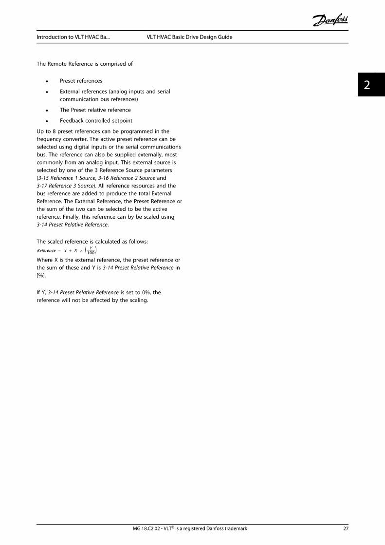
The Remote Reference is comprised of
• Preset references
• External references (analog inputs and serialcommunication bus references)
• The Preset relative reference
• Feedback controlled setpoint
Up to 8 preset references can be programmed in thefrequency converter. The active preset reference can beselected using digital inputs or the serial communicationsbus. The reference can also be supplied externally, mostcommonly from an analog input. This external source isselected by one of the 3 Reference Source parameters(3-15 Reference 1 Source, 3-16 Reference 2 Source and3-17 Reference 3 Source). All reference resources and thebus reference are added to produce the total ExternalReference. The External Reference, the Preset Reference orthe sum of the two can be selected to be the activereference. Finally, this reference can by be scaled using3-14 Preset Relative Reference.
The scaled reference is calculated as follows:Reference = X + X × ( Y
100 )Where X is the external reference, the preset reference orthe sum of these and Y is 3-14 Preset Relative Reference in[%].
If Y, 3-14 Preset Relative Reference is set to 0%, thereference will not be affected by the scaling.
Introduction to VLT HVAC Ba... VLT HVAC Basic Drive Design Guide
MG.18.C2.02 - VLT® is a registered Danfoss trademark 27
2 2

2.6.6 Closed Loop Set-up Wizard
The closed loop setup wizard can be found in the quick menu.
6-29 Terminal 54 Mode[1] Voltage mode
6-25 Terminal 54 High Ref./Feedb. Value
0050 Hz
20-94 PI Integral Time9999 s
Current Voltage
This dialog is forced to be set to [2] Analog in 54
24
25
26
27
28
29
30
31
20-00 Feedback1 source[2] Analog in 54
3-10 Preset reference [0][1] 0
3-03 Max Reference[1] 50
3-02 Min Reference[1] 0
Asynchronous Motor
1-73 Flying Start [0] No
1-22 Motor Voltage0050 V
1-24 Motor current04.66 A
1-25 Motor nominal speed1420 RPM
3-41 Ramp 1 ramp-up time0003 s
3-42 Ramp1 ramp-down time0003 s
3
4
5
6
7
13
14
15
17
18
18a
20
21
22
23
32
33
34
35
36
37
0-03 Regional Settings[0] International
4-12 Motor speed low limit0016 Hz
4-14 Motor speed high limit0050 Hz
1
130B
B631
.11
1-20 Motor Power1.10 kW
1-23 Motor frequency0050 Hz
6-22 Terminal 54 Low Current 4 mA
6-24 Terminal 54 Low Ref./Feedb. Value0016 Hz
6-23 Terminal 54 High Current20 mA
6-25 Terminal 54 High Ref./Feedb. Value50
0,01 s
20-81 PI Normal/Inverse Control[0] Normal
20-83 PI Start Speed0 Hz
20-93 PI Proportional Gain0,01 s
1-29 Automatic Motor Adaption[1] Enable
6-20 Terminal 54 Low Voltage0,07 V
6-24 Terminal 54 Low Ref./Feedb. Value
0 Hz
6-21 Terminal 54 High Voltage10 V
6-26 Terminal 54 Filter time constant
3-10 Preset reference is the set-point
Please note that Terminal 27 Digital Input (par. 5-12) has coast inverse as default setting. This means that AMA can not be performed if there is no 24V to terminal27 so please connect terminal 12 to terminal 27.
0-01 Configuration Mode[0] Open Loop2
Introduction to VLT HVAC Ba... VLT HVAC Basic Drive Design Guide
28 MG.18.C2.02 - VLT® is a registered Danfoss trademark
22

Closed Loop Set-up WizardNo & Name Range Default Function
0-03 Regional Settings [0] International[1] US
0
1-00 Configuration Mode [0] Open loop[3] Closed loop
0 Change this parameter to Closed loop
1-20 Motor Power 0.09-110kW Size related Enter motor power from nameplate data
1-22 Motor Voltage 50.0 - 1000.0V Size related Enter motor voltage from nameplate data
1-23 Motor Frequency 20.0 - 400.0Hz Size related Enter motor frequency from nameplate data
1-24 Motor Current 0.01 - 10000.00A Size related Enter motor current from nameplate data
1-25 Motor Nominal Speed 100.0 - 9999.0RPM Size related Enter motor nominal speed from nameplate data
4-12 Motor Speed Low Limit [Hz] 0.0 - Hz 0.0 Hz Enter the minimum limit for low speed
4-14 Motor Speed High Limit[Hz]
0-Hz 65Hz
3-41 Ramp 1 Ramp up Time 0.05 - 3600.0 s Size related Ramp up time from 0 to rated 1-23 Motor Frequency
3-42 Ramp 1 Ramp Down Time 0.05 - 3600.0 s Size related Ramp down time from rated 1-23 Motor Frequency to 0
1-73 Flying Start [0] Disabled[1] Enabled
0 Select Enable to enable the frequency converter to catch a spinningmotor. I.e. fan applications
3-02 Minimum Reference -4999-4999 0 The minimum reference is the lowest value obtainable by summing allreferences
3-03 Maximum Reference -4999-4999 50 The maximum reference is the highest value obtainable by summingall references
3-10 Preset Reference -100-100% 0 Enter the set point
6-29 Terminal 54 mode [0] Current[1] Voltage
1 Select if terminal 54 is used for current- or voltage input
6-20 Terminal 54 Low Voltage 0-10V 0.07V Enter the voltage that corresponds to the low reference value
6-21 Terminal 54 High Voltage 0-10V 10V Enter the voltage that corresponds to the low high reference value
6-22 Terminal 54 Low Current 0-20mA 4 Enter the current that corresponds to the high reference value
6-23 Terminal 54 High Current 0-20mA 20 Enter the current that corresponds to the high reference value
6-24 Terminal 54 Low Ref./Feedb. Value
-4999-4999 0 Enter the feedback value that corresponds to the voltage or currentset in 6-20 Terminal 54 Low Voltage/6-22 Terminal 54 Low Current
6-25 Terminal 54 High Ref./Feedb. Value
-4999-4999 50 Enter the feedback value that corresponds to the voltage or currentset in 6-21 Terminal 54 High Voltage/6-23 Terminal 54 High Current
6-26 Terminal 54 Filter TimeConstant
0-10 s 0.01 Enter the filter time comstant
20-81 PI Normal/ Inverse Control [0] Normal[1] Inverse
0 Select Normal [0] to set the process control to increase the outputspeed when the process error is positive. Select Inverse [1] to reducethe output speed.
20-83 PI Start Speed [Hz] 0-200Hz 0 Enter the motor speed to be attained as a start signal forcommencement of PI control
20-93 PI Proportional Gain 0-10 0.01 Enter the process controller proportional gain. Quick control isobtained at high amplification. However if amplification is too great,the process may become unstable
20-94 PI Integral Time 0.1-999.0 sec. 999.0 sec. Enter the process controller integral time. Obtain quick control througha short integral time, though if the integral time is too short, theprocess becomes unstable. An excessively long integral time disablesthe integral action.
1-29 Automatic Motor Adaption(AMA)
Off Performing an AMA optimizes motor performance
2.6.7 Tuning the Drive Closed Loop Controller
Once the frequency converter's Closed Loop Controller has been set up, the performance of the controller should be tested.In many cases, its performance may be acceptable using the default values of 20-93 PI Proportional Gain and 20-94 PI IntegralTime. However, in some cases it may be helpful to optimize these parameter values to provide faster system response whilestill controlling speed overshoot.
Introduction to VLT HVAC Ba... VLT HVAC Basic Drive Design Guide
MG.18.C2.02 - VLT® is a registered Danfoss trademark 29
2 2

2.6.8 Manual PI Adjustment
1. Start the motor.
2. Set 20-93 PI Proportional Gain to 0.3 and increase it until the feedback signal begins to oscillate. If necessary, startand stop the frequency converter or make step changes in the set-point reference to attempt to cause oscillation.Next reduce the PI Proportional Gain until the feedback signal stabilizes. Then reduce the proportional gain by40-60%.
3. Set 20-94 PI Integral Time to 20 sec. and reduce it until the feedback signal begins to oscillate. If necessary, startand stop the frequency converter or make step changes in the set-point reference to attempt to cause oscillation.Next, increase the PI Integral Time until the feedback signal stabilizes. Then increase of the Integral Time by15-50%.
2.7 General Aspects of EMC
2.7.1 General Aspects of EMC Emissions
Electrical interference is usually conducted at frequencies in the range 150kHz to 30MHz. Airborne interference from thefrequency converter system in the range 30MHz to 1GHz is generated from the inverter, motor cable, and the motor.As shown in the illustration below, capacitive currents in the motor cable coupled with a high dU/dt from the motorvoltage generate leakage currents.The use of a screened motor cable increases the leakage current (see illustration below) because screened cables havehigher capacitance to earth than unscreened cables. If the leakage current is not filtered, it will cause greater interferenceon the mains in the radio frequency range below approximately 5MHz. Since the leakage current (I1) is carried back to theunit through the screen (I 3), there will in principle only be a small electro-magnetic field (I4) from the screened motor cableaccording to the below figure.
The screen reduces the radiated interference but increases the low-frequency interference on the mains. The motor cablescreen must be connected to the frequency converter enclosure as well as on the motor enclosure. This is best done byusing integrated screen clamps so as to avoid twisted screen ends (pigtails). These increase the screen impedance at higherfrequencies, which reduces the screen effect and increases the leakage current (I4).If a screened cable is used for fieldbus, relay, control cable, signal interface and brake, the screen must be mounted on theenclosure at both ends. In some situations, however, it will be necessary to break the screen to avoid current loops.
Earth Plane
LINE FREQUENCY MOTOR CABLE SCREENED MOTOR
CONVERTER
Earth wire
Screen
z
z
z
L1
L2
L3
PE
U
V
W
PE
175Z
A06
2.11
C S
I 2
I 1
I 3
I 4
C S C S C S
C S
I 4
C Sz PE
If the screen is to be placed on a mounting plate for the frequency converter, the mounting plate must be made of metal,because the screen currents have to be conveyed back to the unit. Moreover, ensure good electrical contact from themounting plate through the mounting screws to the frequency converter chassis.
Introduction to VLT HVAC Ba... VLT HVAC Basic Drive Design Guide
30 MG.18.C2.02 - VLT® is a registered Danfoss trademark
22

When unscreened cables are used, some emission requirements are not complied with, although the immunityrequirements are observed.
In order to reduce the interference level from the entire system (unit + installation), make motor and brake cables as shortas possible. Avoid placing cables with a sensitive signal level alongside motor and brake cables. Radio interference higherthan 50MHz (airborne) is especially generated by the control electronics. Please see 5.1.5 EMC-Correct Electrical Installationformore information on EMC.
2.7.2 Emission Requirements
According to the EMC product standard for adjustable speed frequency converters EN/IEC 61800-3:2004 the EMCrequirements depend on the intended use of the frequency converter. Four categories are defined in the EMC productstandard. The definitions of the 4 categories together with the requirements for mains supply voltage conducted emissionsare given in Table 2.2.
Category DefinitionConducted emission requirement
according to the limits given in EN55011
C1 Frequency converters installed in the first environment (home and office) with asupply voltage less than 1000V.
Class B
C2 Frequency converters installed in the first environment (home and office) with asupply voltage less than 1000V, which are neither plug-in nor movable and areintended to be installed and commissioned by a professional.
Class A Group 1
C3 Frequency converters installed in the second environment (industrial) with a supplyvoltage lower than 1000V.
Class A Group 2
C4 Frequency converters installed in the second environment with a supply voltageequal to or above 1000 V or rated current equal to or above 400A or intended foruse in complex systems.
No limit line.An EMC plan should be made.
Table 2.2 Emission Requirements
When the generic emission standards are used the frequency converters are required to comply with the following limits
Environment Generic standardConducted emission requirement
according to the limits given in EN 55011
First environment(home and office)
EN/IEC 61000-6-3 Emission standard for residential, commercialand light industrial environments.
Class B
Second environment(industrial environment)
EN/IEC 61000-6-4 Emission standard for industrial environments. Class A Group 1
Introduction to VLT HVAC Ba... VLT HVAC Basic Drive Design Guide
MG.18.C2.02 - VLT® is a registered Danfoss trademark 31
2 2

2.7.3 EMC Test Results
The following test results have been obtained using a system with a frequency converter, a screened control cable, a controlbox with potentiometer, as well as a motor screened cable.
RFI Filter Type Conduct emission. Maximum shielded cable length Radiated emission
Industrial environmentHousing, trades and
light industriesIndustrial
environmentHousing, trades and
light industries
EN 55011 Class A2 EN 55011 Class A1 EN 55011 Class B EN 55011 Class A1 EN 55011 Class B
Withoutexternal
filter
Withexternal
filter
Withoutexternal
filter
Withexternal
filter
Withoutexternal
filter
Withexternal
filter
Withoutexternal
filter
Withexternal
filter
Withoutexternal
filter
Withexternal
filter
H4 RFI filter(Class A1)
0.25-11kW3x200-240V IP20
25m 50m 20m Yes Yes -
0.37-22kW3x380-480V IP20
25m 50m 20m Yes Yes -
H2 RFI filter(Class A2)
1.5-45kW3x200-240V IP20
25m no -
30-90kW3x380-480V IP20
25m no -
22-90kW3x380-480V IP54
25m no -
H3 RFI filter(Class A1/B)
1.5-45kW3x200-240V IP20
50m 20m yes -
30-90kW3x380-480V IP20
50m 20m yes -
22-90kW3x380-480V IP54
50m 10m yes -
Introduction to VLT HVAC Ba... VLT HVAC Basic Drive Design Guide
32 MG.18.C2.02 - VLT® is a registered Danfoss trademark
22

2.7.4 General Aspects of HarmonicsEmission
A frequency converter takes up a non-sinusoidal currentfrom mains, which increases the input current IRMS. A non-sinusoidal current is transformed by means of a Fourieranalysis and split up into sine-wave currents with differentfrequencies, i.e. different harmonic currents I N with 50Hzas the basic frequency:
Harmonic currents I1 I5 I7
Hz 50Hz 250Hz 350Hz
The harmonics do not affect the power consumptiondirectly but increase the heat losses in the installation(transformer, cables). Consequently, in plants with a highpercentage of rectifier load, maintain harmonic currents ata low level to avoid overload of the transformer and hightemperature in the cables.
175H
A03
4.10
NOTESome of the harmonic currents might disturb communi-cation equipment connected to the same transformer orcause resonance in connection with power-factorcorrection batteries.
To ensure low harmonic currents, the frequency converteris equipped with intermediate circuit coils as standard. Thisnormally reduces the input current I RMS by 40%.
The voltage distortion on the mains supply voltagedepends on the size of the harmonic currents multipliedby the mains impedance for the frequency in question.The total voltage distortion THD is calculated on the basisof the individual voltage harmonics using this formula:
THD % = U 25 + U 2
7 + ... + U 2N
(UN% of U)
2.7.5 Harmonics Emission Requirements
Equipment connected to the public supply network
Options: Definition:
1 IEC/EN 61000-3-2 Class A for 3-phase balancedequipment (for professional equipment only up to1kW total power).
2 IEC/EN 61000-3-12 Equipment 16A-75A and profes-sional equipment as from 1kW up to 16A phasecurrent.
2.7.6 Harmonics Test Results (Emission)
Power sizes up to PK75 in T2 and T4 complies with IEC/EN61000-3-2 Class A. Power sizes from P1K1 and up to P18Kin T2 and up to P90K in T4 complies with IEC/EN61000-3-12, Table 4.
Individual Harmonic Current In/I1 (%)
I5 I7 I11 I13
Actual 0.25-11kW,200V (typical)
32.6 16.6 8.0 6.0
Limit for Rsce≥120 40 25 15 10
Harmonic current distortion factor (%)
THD PWHD
Actual 0.25-11kW,200V (typical)
39 41.4
Limit for Rsce≥120 48 46
Individual Harmonic Current In/I1 (%)
I5 I7 I11 I13
Actual 0.37-22kW,380-480V (typical)
36.7 20.8 7.6 6.4
Limit for Rsce≥120 40 25 15 10
Harmonic current distortion factor (%)
THD PWHD
Actual 0.37-22kW,380-480V (typical)
44.4 40.8
Limit for Rsce≥120 48 46
Individual Harmonic Current In/I1 (%)
I5 I7 I11 I13
Actual 30-90kW,380-480V (typical)
36.7 13.8 6.9 4.2
Limit for Rsce≥120 40 25 15 10
Harmonic current distortion factor (%)
THD PWHD
Actual 30-90kW,380-480V (typical)
40.6 28.8
Limit for Rsce≥120 48 46
Provided that the short-circuit power of the supply Ssc isgreater than or equal to:
Introduction to VLT HVAC Ba... VLT HVAC Basic Drive Design Guide
MG.18.C2.02 - VLT® is a registered Danfoss trademark 33
2 2

SSC = 3 × RSCE × Umains × Iequ = 3 × 120 × 400 × Iequat the interface point between the user’s supply and thepublic system (Rsce).
It is the responsibility of the installer or user of theequipment to ensure, by consultation with the distributionnetwork operator if necessary, that the equipment isconnected only to a supply with a short-circuit power Ssc
greater than or equal to specified above.Other power sizes can be connected to the public supplynetwork by consultation with the distribution networkoperator.
Compliance with various system level guidelines:The harmonic current data in the table are given inaccordance with IEC/EN 61000-3-12 with reference to thePower Drive Systems product standard. They may be usedas the basis for calculation of the harmonic currents'influence on the power supply system and for thedocumentation of compliance with relevant regionalguidelines: IEEE 519 -1992; G5/4.
2.7.7 Immunity Requirements
The immunity requirements for frequency convertersdepend on the environment where they are installed. Therequirements for the industrial environment are higherthan the requirements for the home and officeenvironment. All Danfoss frequency converters complywith the requirements for the industrial environment andconsequently comply also with the lower requirements forhome and office environment with a large safety margin.
2.8 Galvanic Isolation (PELV)
2.8.1 PELV - Protective Extra Low Voltage
PELV offers protection by way of extra low voltage.Protection against electric shock is ensured when theelectrical supply is of the PELV type and the installation ismade as described in local/national regulations on PELVsupplies.
All control terminals and relay terminals 01-03/04-06comply with PELV (Protective Extra Low Voltage) (Does notapply to grounded Delta leg above 440V).
Galvanic (ensured) isolation is obtained by fulfillingrequirements for higher isolation and by providing therelevant creapage/clearance distances. These requirementsare described in the EN 61800-5-1 standard.
The components that make up the electrical isolation, asdescribed below, also comply with the requirements for
higher isolation and the relevant test as described in EN61800-5-1.The PELV galvanic isolation can be shown in 5 locations(see illustration):
To maintain PELV all connections made to the controlterminals must be PELV, e.g. thermistor must bereinforced/double insulated.
0.25-22kW
1. Power supply (SMPS)
2. Opto-couplers, communication between AOC andBOC
3. Custom relays
SMPS
130B
B896
.10
12
3
a
M
The functional galvanic isolation (a on drawing) is for theRS-485 standard bus interface.
CAUTIONInstallation at high altitude:At altitudes above 2km, please contact Danfoss regardingPELV.
2.9 Earth Leakage Current
WARNINGDISCHARGE TIMETouching the electrical parts could be fatal - even after theequipment has been disconnected from mains.Also make sure that other voltage inputs have beendisconnected, such as load sharing (linkage of DCintermediate circuit), as well as the motor connection forkinetic back-up.Before touching any electrical parts, wait at least theamount of time indicated in the Safety Precautions section.Shorter time is allowed only if indicated on the nameplatefor the specific unit.
Introduction to VLT HVAC Ba... VLT HVAC Basic Drive Design Guide
34 MG.18.C2.02 - VLT® is a registered Danfoss trademark
22

NOTELeakage CurrentThe earth leakage current from the frequency converterexceeds 3.5mA. To ensure that the earth cable has a goodmechanical connection to the earth connection, the cablecross section must be at least 10mm2 or 2 rated earthwires terminated separately.Residual Current DeviceThis product can cause a DC current in the protectiveconductor. Where a residual current device (RCD) is usedfor protection in case of direct or indirect contact, only anRCD of Type B is allowed on the supply side of thisproduct. Otherwise, another protective measure shall beapplied, such as separation from the environment bydouble or reinforced insulation, or isolation from thesupply system by a transformer. See also Application NoteProtection against Electrical Hazards MN.90.G2.02.Protective earthing of the frequency converter and the useof RCDs must always follow national and local regulations.
2.10 Extreme Running Conditions
Short Circuit (Motor Phase – Phase)The frequency converter is protected against short circuitsby means of current measurement in each of the threemotor phases or in the DC link. A short circuit betweentwo output phases will cause an overcurrent in theinverter. The inverter will be turned off individually whenthe short circuit current exceeds the permitted value(Alarm 16 Trip Lock).To protect the frequency converter against a short circuitat the load sharing and brake outputs please see thedesign guidelines.See certificate in the Certificates section.
Switching on the OutputSwitching on the output between the motor and thefrequency converter is fully permitted. The frequencyconverter will not be damaged in any way by switching onthe output. However, fault messages may appear.
Motor-generated Over-voltageThe voltage in the intermediate circuit is increased whenthe motor acts as a generator. This occurs in followingcases:
1. The load drives the motor (at constant outputfrequency from the frequency converter), ie. theload generates energy.
2. During deceleration ("ramp-down") if the momentof inertia is high, the friction is low and the ramp-down time is too short for the energy to bedissipated as a loss in the frequency converter,the motor and the installation.
3. Incorrect slip compensation setting (1-62 SlipCompensation) may cause higher DC link voltage.
The control unit may attempt to correct the ramp ifpossible (2-17 Over-voltage Control.)The inverter turns off to protect the transistors and theintermediate circuit capacitors when a certain voltage levelis reached.
Mains Drop-outDuring a mains drop-out, the frequency converter keepsrunning until the intermediate circuit voltage drops belowthe minimum stop level, which is typically 15% below thefrequency converter's lowest rated supply voltage. Themains voltage before the drop-out and the motor loaddetermines how long it takes for the inverter to coast.
2.10.1 Motor Thermal Protection
This is the way Danfoss protects the motor from beingoverheated. It is an electronic feature that simulates abimetal relay based on internal measurements. The charac-teristic is shown in the following figure.
1.21.0 1.4
30
1020
10060
4050
1.81.6 2.0
2000
500
200
400300
1000600
t [s]
175Z
A05
2.12
fOUT = 2 x f M,N
fOUT = 0.2 x f M,N
fOUT = 1 x f M,N(par. 1-23)
IM,N(par. 1-24)IM
The X-axis is showing the ratio between Imotor and Imotor
nominal. The Y-axis is showing the time in seconds beforethe ETR cuts off and trips the drive. The curves areshowing the characteristic nominal speed at twice thenominal speed and at 0.2x the nominal speed.
It is clear that at lower speed the ETR cuts of at lower heatdue to less cooling of the motor. In that way the motorare protected from being over heated even at low speed.The ETR feature is calculating the motor temperaturebased on actual current and speed.
The thermistor cut-out value is > 3kΩ.
Integrate a thermistor (PTC sensor) in the motor forwinding protection.
Introduction to VLT HVAC Ba... VLT HVAC Basic Drive Design Guide
MG.18.C2.02 - VLT® is a registered Danfoss trademark 35
2 2
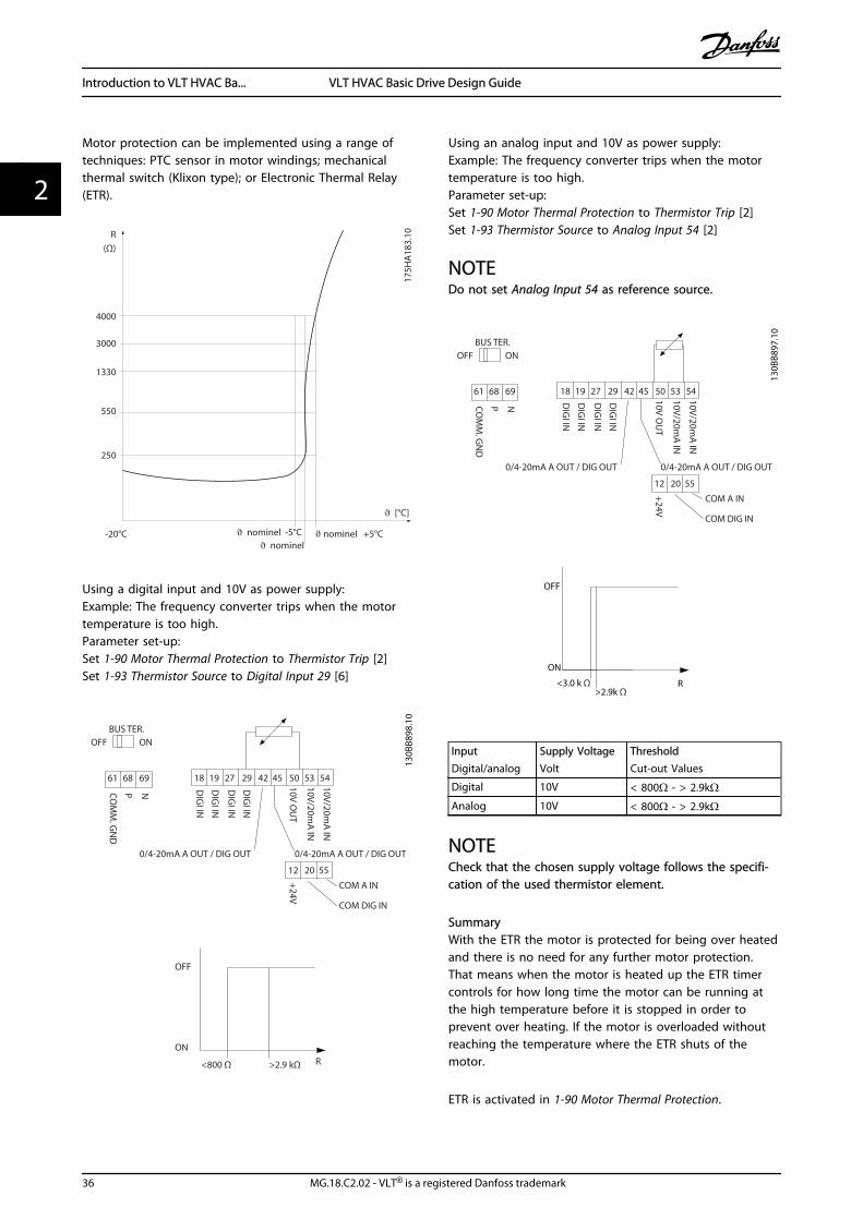
Motor protection can be implemented using a range oftechniques: PTC sensor in motor windings; mechanicalthermal switch (Klixon type); or Electronic Thermal Relay(ETR).
1330
550
250
-20°C
175H
A18
3.10
4000
3000
R(Ω)
nominel nominel -5°C nominel +5°C
[°C]
Using a digital input and 10V as power supply:Example: The frequency converter trips when the motortemperature is too high.Parameter set-up:Set 1-90 Motor Thermal Protection to Thermistor Trip [2]Set 1-93 Thermistor Source to Digital Input 29 [6]
R
OFF
ON
<800 Ω >2.9 kΩ
18 19
12 20 55
27 29 42 45 50 53 54
DIG
I IN
DIG
I IN
DIG
I IN
DIG
I IN
61 68 69
NPCOM
M. G
ND
+24V
0/4-20mA A OUT / DIG OUT 0/4-20mA A OUT / DIG OUT
COM A IN
COM DIG IN
10V/20mA
IN
10V/20mA
IN
10V OU
T
BUS TER.OFF ON
130B
B898
.10
Using an analog input and 10V as power supply:Example: The frequency converter trips when the motortemperature is too high.Parameter set-up:Set 1-90 Motor Thermal Protection to Thermistor Trip [2]Set 1-93 Thermistor Source to Analog Input 54 [2]
NOTEDo not set Analog Input 54 as reference source.
18 19
12 20 55
27 29 42 45 50 53 54
DIG
I IN
DIG
I IN
DIG
I IN
DIG
I IN
61 68 69
NPCOM
M. G
ND
+24V
0/4-20mA A OUT / DIG OUT 0/4-20mA A OUT / DIG OUT
COM A IN
COM DIG IN
10V/20mA
IN
10V/20mA
IN
10V OU
T
BUS TER.OFF ON
130B
B897
.10
R<3.0 k Ω>2.9k Ω
OFF
ON
InputDigital/analog
Supply VoltageVolt
ThresholdCut-out Values
Digital 10V < 800Ω - > 2.9kΩAnalog 10V < 800Ω - > 2.9kΩ
NOTECheck that the chosen supply voltage follows the specifi-cation of the used thermistor element.
SummaryWith the ETR the motor is protected for being over heatedand there is no need for any further motor protection.That means when the motor is heated up the ETR timercontrols for how long time the motor can be running atthe high temperature before it is stopped in order toprevent over heating. If the motor is overloaded withoutreaching the temperature where the ETR shuts of themotor.
ETR is activated in 1-90 Motor Thermal Protection.
Introduction to VLT HVAC Ba... VLT HVAC Basic Drive Design Guide
36 MG.18.C2.02 - VLT® is a registered Danfoss trademark
22
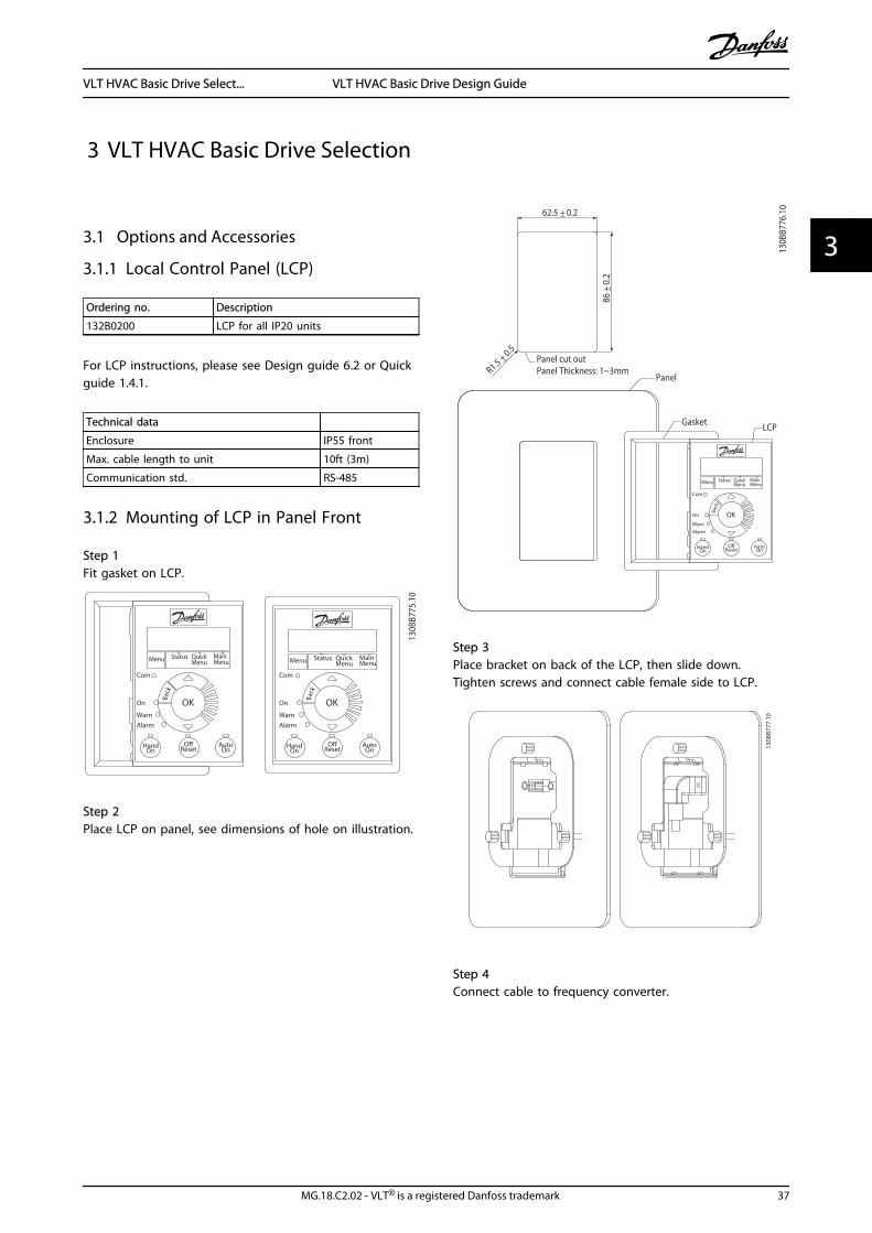
3 VLT HVAC Basic Drive Selection
3.1 Options and Accessories
3.1.1 Local Control Panel (LCP)
Ordering no. Description
132B0200 LCP for all IP20 units
For LCP instructions, please see Design guide 6.2 or Quickguide 1.4.1.
Technical data
Enclosure IP55 front
Max. cable length to unit 10ft (3m)
Communication std. RS-485
3.1.2 Mounting of LCP in Panel Front
Step 1Fit gasket on LCP.
Status MainMenu
QuickMenuMenu
Back
Com
Status MainMenu
QuickMenu
HandOn
OK
Menu
OReset
AutoOn
AlarmWarn
On
Com
AlarmWarn
On
130B
B775
.10
Back
HandOn
OK
OReset
AutoOn
Step 2Place LCP on panel, see dimensions of hole on illustration.
Gasket
R1.5 +_ 0.5
62.5 +_ 0.2
Panel cut outPanel Thickness: 1~3mm
86 +_
0.2
LCP
Panel
130B
B776
.10
Status MainMenu
QuickMenuMenu
Com
Alarm
Warn
On
Back
HandOn
OK
OffReset
AutoOn
Step 3Place bracket on back of the LCP, then slide down.Tighten screws and connect cable female side to LCP.
130B
B777
.10
Step 4Connect cable to frequency converter.
VLT HVAC Basic Drive Select... VLT HVAC Basic Drive Design Guide
MG.18.C2.02 - VLT® is a registered Danfoss trademark 37
3 3

130B
B778
.10
VLT
NOTEUse the provided thread cutting screws to fastenconnector to the frequency converter, Tightening torque1.3Nm.
VLT HVAC Basic Drive Select... VLT HVAC Basic Drive Design Guide
38 MG.18.C2.02 - VLT® is a registered Danfoss trademark
33

3.1.3 IP21/TYPE 1 Enclosure Kit
IP21/TYPE 1 is an optional enclosure element available for IP20 units.If the enclosure kit is used, an IP20 unit is upgraded to comply with enclosure IP21/TYPE 1.
H1-H5
130B
B902
.10
H6-H8
130B
B903
.10
Frame IP class Power Height (mm)A
Width (mm)B
Depth (mm)C
IP21 kitordering no.
Type 1 kitordering no.3x200-240V 3x380-480V 3x525-600V
H1 IP20 0.25-1.5kW/0.33-2Hp
0.37-1.5kW/0.5-2Hp
293 81 173 132B0212 132B0222
H2 IP20 2.2kW/ 3Hp 2.2-4kW/3-5.4Hp
322 96 195 132B0213 132B0223
H3 IP20 3.7kW/ 5Hp 5.5-7.5 kW/7.5-10 Hp
346 106 210 132B0214 132B0224
H4 IP20 5.5-7,5kW/7.5-10Hp
11-15kW/15-20Hp
374 141 245 132B0215 132B0225
H5 IP20 11kW/ 15Hp 18.5-22kW/25-30Hp
418 161 260 132B0216 132B0226
H6 IP20 15-18.5kW/20-25Hp
30-45kW/40-60Hp
22-30kW/30-40Hp
663 260 242 132B0217 132B0217
H7 IP20 22-30kW/30-40Hp
55-75kW/100-120Hp
45-55kW/60-100Hp
807 329 335 132B0218 132B0218
H8 IP20 37-45kW/50-60Hp
90kW/125Hp
75-90kW/120-125Hp
943 390 335 132B0219 132B0219
H9 IP20 2.2-7.5kW/3-10Hp
372 130 205 132B0220 132B0220
H10 IP20 11-15kW/15-20Hp
475 165 249 132B0221 132B0221
VLT HVAC Basic Drive Select... VLT HVAC Basic Drive Design Guide
MG.18.C2.02 - VLT® is a registered Danfoss trademark 39
3 3

3.1.4 Decoupling Plate
Use the decoupling plate for EMC correct installation.
Shown here on a H3 enclosure.
130B
B793
.10
99 99
Power Decoupling plate
Frame IP class 3x200-240V 3x380-480V 3x525-600V
H1 IP20 0.25-1.5kW/ 0.33-2Hp 0.37-1.5kW/ 0.5-2Hp 132B0202
H2 IP20 2.2kW/ 3Hp 2.2-4kW/ 3-5.4Hp 132B0202
H3 IP20 3.7kW/ 5Hp 5.5-7.5kW/ 7.5-10Hp 132B0204
H4 IP20 5.5-7,5kW/7.5-10Hp 11-15kW/15-20Hp 132B0205
H5 IP20 11kW/15Hp 18.5-22kW/25-30Hp 130B0205
H6 IP20 15-18.5kW/20-25Hp 30kW/40Hp 22-30kW/30-40Hp 132B0207
H6 IP20 37-45kW/50-60Hp 132B0242
H7 IP20 22-30kW/30-40Hp 55kW/75Hp 45-55kW/60-100Hp 132B0208
H7 IP20 75kW/100Hp 132B0243
H8 IP20 37-45kW/50-60Hp 90kW/125Hp 75-90kW/120-125Hp 132B0209
Note: For H9, H10 Drive, the decoupling plates are included in accessory bag.
VLT HVAC Basic Drive Select... VLT HVAC Basic Drive Design Guide
40 MG.18.C2.02 - VLT® is a registered Danfoss trademark
33

4 How to Order
4.1.1 Drive Configurator
It is possible to design a frequency converter according to the application requirements by using the ordering numbersystem.
Frequency converters can be ordered as standard or with internal options by using a type code string, i.e.
FC-101PK25T2E20H4XXCXXXSXXXXAXBXCXXXXDX
Use the Internet based Drive Configurator to configure the right frequency converter for the right application and generatethe type code string. The Drive Configurator will automatically generate an eight-digit sales number to be delivered to yourlocal sales office.Furthermore, a project list with several products can be established and sent it Danfoss sales representative.
The Drive Configurator can be found on the global Internet site: www.danfoss.com/drives.
How to Order VLT HVAC Basic Drive Design Guide
MG.18.C2.02 - VLT® is a registered Danfoss trademark 41
4 4

4.1.2 Type Code String
F C - P T H
130B
B899
.10
X S A B CX X X X
1 2 3 4 5 6 7 8 9 10 11 12 13 14 15 16 17 18 19 20 302221 23 272524 26 28 29 31 373635343332 38 39
X0 D1 1 X X X X X X X X X
Description Pos. Possible choise
Product group & FC series 1-6 FC 101
Power rating 7-10 0.25-90kW (PK25-P90K)
Number of phases 11 Three phases (T)
Mains voltage 11-12 T2: 200-240V ACT4: 380-480V ACT6: 525-600V AC
Enclosure 13-15 E20: IP20/ChassisP20: IP20/Chassis with back plateE5A: IP54P5A: IP54 with back plate
RFI filter 16-17 H1: RFI filter class A1/BH2: RFI filter class A2H3: RFI filter class A1/B (reduced cable length)H4: RFI filter calss A1
Brake 18 X: No brake chopper included
Display 19 A: Alpha Numeric Local Control PanelX: No Local Control Panel
Coating PCB 20 X: No coated PCBC: Coated PCB
Mains option 21 X: No mains option
Adaption 22 X: No adaption
Adaption 23 X: No adaption
Software release 24-27 SXXXX: Latest release - std. software
Software language 28 X: Standard
A options 29-30 AX: No A options
B options 31-32 BX: No B options
C0 options MCO 33-34 CX: No C options
C1 options 35 X: No C1 options
C option software 36-37 XX: No options
D options 38-39 DX: No D0 options
Table 4.1 Type Code Descriptions
How to Order VLT HVAC Basic Drive Design Guide
42 MG.18.C2.02 - VLT® is a registered Danfoss trademark
44

4.2.1 Ordering Numbers: Options and Accessories
Encl
osur
efr
ame
size
Mai
ns v
olta
geH
1H
2H
3H
4H
5H
6H
7H
8
T2 (2
00-2
40V
AC)
0.25
-1,5
kW/
0.33
-2H
p2.
2kW
/3H
p3.
7kW
/5H
p5.
5-7.
5kW
/7.
5-10
Hp
11kW
/15H
p15
kW/2
0Hp
18.5
kW/2
5Hp
22kW
/30H
p30
kW/4
0Hp
37-4
5kW
/50
-60H
p
T4
(380
-480
VAC)
0.37
-1.5
kW/
0.5-
2Hp
2.2-
4kW
/3-
5.4H
p5.
5-7.
5kW
/7.
5-10
Hp
11-1
5kW
/15
-20H
p18
.5-2
2/25
-30H
p30
kW/
40H
p37
-45k
W/
50-6
0Hp
55kW
/75
Hp
75kW
/10
0Hp
90kW
/12
5Hp
T6(5
25-6
00VA
C)22
kW/3
0Hp
30kW
/40H
p45
kW/6
0Hp
55kW
/100
Hp
75-9
0kW
/12
0-12
5Hp
Des
crip
tion
LCP
13
2B02
00LC
P pa
nel
mou
ntin
g k
it IP
55in
cl. 3
m c
able
132B
0201
Dec
oupl
ing
pla
te
132B
0202
132B
0202
132B
0204
132B
0205
132B
0205
132B
0207
132B
0242
132B
0208
132B
0243
132B
0209
IP21
opt
ion
132B
0212
132B
0213
132B
0214
132B
0215
132B
0216
132B
0217
132B
0218
132B
0219
Nem
a Ty
pe 1
Kit
13
2B02
2213
2B02
2313
2B02
2413
2B02
2513
2B02
2613
2B02
1713
2B02
1813
2B02
19
Tabl
e 4.
2 O
ptio
ns a
nd A
cces
sorie
s
How to Order VLT HVAC Basic Drive Design Guide
MG.18.C2.02 - VLT® is a registered Danfoss trademark 43
4 4

4.2.2 Harmonic Filters
3 x 380 - 480Volt 50Hz
Power[kW]
Drive inputcurrent
Continuous
Defaultswitchingfrequency
THIDlevel
Ordernumber
filter IP00
Codenumber
filter IP20
22 kW 41.5 A 4 kHz 3.7% 130B1397 130B1239
30 kW 57 A 4 kHz 2.9% 130B1398 130B1240
37 kW 70 A 4 kHz 3.4% 130B1442 130B1247
45 kW 84 A 3 kHz 3.1% 130B1442 130B1247
55 kW 103 A 3 kHz 5.5% 130B1444 130B1249
75 kW 140 A 3 kHz 3.9% 130B1445 130B1250
90 kW 176 A 3 kHz 3.9% 130B1445 130B1250
Table 4.3 AHF Filters (5% current distortion)
3 x 380 - 480Volt 50Hz
Power[kW]
Drive inputcurrent
Continuous
Defaultswitchingfrequency
THIDlevel
Ordernumber
filter IP00
Codenumber
filter IP20
22 kW 41.5 A 4 kHz 6.2% 130B1274 130B1111
30 kW 57 A 4 kHz 6.4% 130B1275 130B1176
37 kW 70 A 4 kHz 9.5% 130B1291 130B1201
45 kW 84 A 3 kHz 9.3% 130B1291 130B1201
55 kW 103 A 3 kHz 11.5% 130B1293 130B1207
75 kW 140 A 3 kHz 8.3% 130B1294 130B1213
90 kW 176 A 3 kHz 8.3% 130B1294 130B1213
Table 4.4 AHF Filters (10% current distortion)
3 x 440 - 480Volt 60Hz
Power[kW]
Drive inputcurrent
Continuous
Defaultswitchingfrequency
THIDlevel
Ordernumber
filter IP00
Codenumber
filter IP20
22 kW 34.6 A 4 kHz 3.5% 130B1792 130B1757
30 kW 49 A 4 kHz 3.2% 130B1793 130B1758
37 kW 61 A 4 kHz 3.5% 130B1794 130B1759
45 kW 73 A 3 kHz 3.7% 130B1795 130B1760
55 kW 89 A 3 kHz 3.6% 130B1796 130B1761
75 kW 121 A 3 kHz 5.5% 130B1797 130B1762
90 kW 143 A 3 kHz 4.8% 130B1798 130B1763
Table 4.5 AHF Filters (5% current distortion)
3 x 440 - 480Volt 60Hz
Power[kW]
Drive inputcurrent
Continuous
Defaultswitchingfrequency
THIDlevel
Ordernumber
filter IP00
Codenumber
filter IP20
22 kW 34.6 A 4 kHz 6.5% 130B1775 130B1487
30 kW 49 A 4 kHz 7.6% 130B1776 130B1488
37 kW 61 A 4 kHz 7.5% 130B1777 130B1491
45 kW 73 A 3 kHz 8.8% 130B1778 130B1492
55 kW 89 A 3 kHz 8.5% 130B1779 130B1493
75 kW 121 A 3 kHz 12.5% 130B1780 130B1494
90 kW 143 A 3 kHz 10.2% 130B1781 130B1495
Table 4.6 AHF Filters (10% current distortion)
4.2.3 External RFI Filter
External filters to fulfil A1 50 meters / B1 20 meters
Power Size 380-480V Type A B C D E F G H I J K L1 Torque [Nm] Weight Ordering Number
0.37-2.2kW FN3258-7-45 190 40 70 160 180 20 4.5 1 10.6 M5 20 31 0.7 - 0.8Nm 0.5kg 132B0244
3-7.5kW FN3258-16-45 250 45 70 220 235 25 4.5 1 10.6 M5 22.5 31 0.7 - 0.8Nm 0.8kg 132B0245
11-15kW FN3258-30-47 270 50 85 240 255 30 5.4 1 10.6 M5 25 40 1.9 - 2.2Nm 1.2kg 132B0246
18.5-22kW FN3258-42-47 310 50 85 280 295 30 5.4 1 10.6 M5 25 40 1.9 - 2.2Nm 1.4kg 132B0247
How to Order VLT HVAC Basic Drive Design Guide
44 MG.18.C2.02 - VLT® is a registered Danfoss trademark
44

5 How to Install
Encl
osur
e fr
ame
size
Mai
ns v
olta
geH
1H
2H
3H
4H
5H
6H
7H
8
T2 (2
00-
240V
AC)
0.25
-1,5
kW/
0.33
-2H
p2.
2kW
/3H
p3.
7kW
/5H
p5.
5-7,
5kW
/7.
5-10
Hp
11kW
/15
Hp
T4 (3
80-
480V
AC)
0.37
-1.5
kW/
0.5-
2Hp
2.2-
4kW
/3-
5.4H
p5.
5-7.
5kW
/7.
5-10
Hp
11-1
5kW
/15
-20H
p18
.5-2
2/25
-30H
p30
-45k
W/
40-6
0Hp
55-7
5kW
/73
-100
Hp
90kW
/12
5Hp
IP
IP
20IP
20IP
20IP
20IP
20IP
20IP
20IP
20H
eigh
t
Encl
osur
eA
19
5mm
/7.7
inch
227/
8.4
inch
255m
m/1
0 in
ch29
6mm
/11.
7 in
ch33
4mm
/13.
1 in
ch51
8mm
/20.
4 in
ch55
0mm
/21.
7 in
ch66
0mm
/26
inch
Hei
gth
incl
.de
coup
ling
pla
te
27
3mm
/10
.7 in
ch30
3/11
.9 in
ch32
9mm
/13
inch
359m
m/
14.1
inch
402m
m/
15.8
inch
595m
m/
23.4
inch
635m
m/
25in
ch(4
5kW
)
630m
m/
24.8
inch
690m
m/
27.2
inch
(75k
W)
800m
m/
31.5
inch
Betw
een
mou
ntin
gho
les
a
183m
m/
7.2i
nch
212/
8.3
inch
240m
m/
9.4
inch
275m
m/
10.8
inch
314m
m/
12.4
inch
495m
m/
19.5
inch
521m
m/
20.5
inch
631m
m/
24.8
inch
Wid
thB
75
mm
/3
inch
90/
3.5
inch
100m
m/
3.9
inch
135m
m/
5.3
inch
150m
m/
5.9
inch
239m
m/
31.5
inch
313m
m/
12.3
inch
375m
m/
14.8
inch
Betw
een
mou
ntin
gho
les
b
56m
m/
2.2
inch
65/
2.6
inch
74m
m/
2.9
inch
105m
m/
4.1
inch
120m
m/
4.7
inch
200m
m/
7.9
inch
270m
m/
10.6
inch
330m
m/
13 in
ch
Dep
thC
16
8mm
/6.
6 in
ch19
0mm
/7.
5 in
ch20
6mm
/8.
1 in
ch24
1mm
/9.
5 in
ch25
5mm
/10
inch
242m
m/
9.5
inch
335m
m/
13.2
inch
335m
m/
13.2
inch
Mou
ntin
g h
oles
d
9mm
/0.
35 in
ch11
mm
/0.
43 in
ch11
mm
/0.
43 in
ch12
.6m
m/
0.50
inch
12.6
mm
/0.
50 in
ch-
--
e
4.
5mm
/0.1
8in
ch5.
5mm
/0.2
2in
ch5.
5mm
/0.2
2 in
ch7m
m/0
.28
inch
7mm
/0.2
8 in
ch8.
5mm
8.5m
m8.
5mm
f
5.
3mm
/0.
21 in
ch7.
4mm
/0.
29 in
ch8.
1mm
/0.
32 in
ch8.
4mm
/0.
33 in
ch8.
5mm
/0.
33 in
ch15
mm
17m
m17
mm
Max
imum
wei
ght
2.1k
g3.
4kg
4.5k
g7.
9kg
9.5k
g24
.5kg
36kg
51kg
Ship
ping
dim
ensi
ons
Hei
ght
255m
m/
10.0
inch
300m
m/
11.8
inch
330m
m/
13.0
inch
380m
m/
15.0
inch
420m
m/
16.5
inch
460m
m/
18.1
inch
540m
m/
21.3
inch
490m
m/
19.3
inch
Wid
th
15
4mm
/6.
1inc
h17
0mm
/6.
7inc
h18
8mm
/7.
4inc
h25
0mm
/9.
8inc
h29
0mm
/11
.4in
ch85
0mm
/33
.5 in
ch85
0mm
/33
.5 in
ch95
0mm
/37
.4 in
ch
Dep
th
23
5mm
/9.3
inch
260m
m/1
0.2
inch
282m
m/1
1.1
inch
375m
m/1
4.8
inch
375m
m/1
4.8i
nch
370m
m/1
4.6
inch
410m
m/1
6.1
inch
490m
m/1
9.3
inch
Tabl
e 5.
1 M
echa
nica
l Fro
nt V
iew
s
How to Install VLT HVAC Basic Drive Design Guide
MG.18.C2.02 - VLT® is a registered Danfoss trademark 45
5 5

EnclosurePower[kW]
Height[mm]
Width[mm]
Depth[mm]
Mounting hole[mm]
Max. weight
FrameIP
class3x200-240V
3x380-480V
3x525-600V
AA incl
Decouplingplate
a B b C d e f Kg
H6 20 15-18.5 30-45 22-30 518 595-635 495 239 200 242 - 8.5 15 24.5
H7 20 22-30 55-75 45-55 550 630-690 521 313 270 335 - 8.5 17 36
H8 20 37-45 90 75-90 660 800 631 375 330 335 - 8.5 17 51
H9 20 - - 2.2-7.5 268 374 257 130 110 205 11 5.5 9.0 6.6
H10 20 - - 11-15 399 419 380 165 140 248 12 6.8 7.9 12.0
I6 54 - 22-37 - 650 - 624 242 210 260 19 9.0 9.0 27.0
I7 54 - 45-55 - 680 - 648 308 272 310 19 9.0 9.8 45.0
I8 54 - 75-90 - 770 - 739 370 334 335 19 9.0 9.8 65.0
The above mentioned dimensions are only for the physicalunits, but when installing in an application it is necessaryto add space for free air passage both above and belowthe units. The amount of space for free air passage is listedin the following table:
Enclosure Clearance needed for free air passage [mm]
Frame IP class Above unit Below unit
H6 20 200 200
H7 20 200 200
H8 20 225 225
H9 20 100 100
H10 20 200 200
I6 54 200 200
I7 54 200 200
I8 54 225 225
5.1.1 Side-by-Side Installation
The frequency converter can be mounted side-by-side and requires the clearance above and below for cooling.
Power Clearance above/below (mm/inch)
Frame IP class 3x200-240V 3 x 380-480V 3 x 525-600V
H1 IP20 0.25-1.5kW/0.33-2Hp 0.37-1.5kW/0.5-2Hp 100/4
H2 IP20 2.2kW/3Hp 2.2-4kW/3-5.4Hp 100/4
H3 IP20 3.7kW/5Hp 5.5-7.5 kW/7.5-10 Hp 100/4
H4 IP20 5.5-7.5kW/7.5-10Hp 11-15kW/15-20Hp 100/4
H5 IP20 11kW/15 Hp 18.5-22kW/25-30Hp 100/4
H6 IP20 15-18.5Kw/20-25Hp 30-45kW/40-60Hp 22-30kW/30-40Hp 200/7.9
H7 IP20 22-30kW/30-40Hp 55-75kW/100-120Hp 45-55kW/60-100Hp 200/7.9
H8 IP20 37-45kW/50-60Hp 90kW/125Hp 75-90kW/120-125Hp 225/8.9
H9 IP20 2.2-7.5kW/3-10Hp 100/4
H10 IP20 11-15kW/15-20Hp 200/7.9
NOTEWith IP21/Nema Type1 option kit mounted, a distance of 50mm between the units is required.
How to Install VLT HVAC Basic Drive Design Guide
46 MG.18.C2.02 - VLT® is a registered Danfoss trademark
55

5.1.2 Field Mounting
IP21/TYPE 1 kits are recommended.
5.2 Electrical Data
5.2.1 Electrical Overview
L1L2L3
3 Phasepowerinput
PE PE
+10Vdc
0-10Vdc-
0-10Vdc-
50 (+10V OUT)
54 (A IN)
53 (A IN)
55 (COM A IN/OUT)
0/4-20 mA
0/4-20 mA
42 0/4-20mA A OUT / DIG OUT
45 0/4-20mA A OUT / DIG OUT
18 (DIGI IN)
19 (DIGI IN)
27 (DIGI IN)
29 (DIGI IN)
12 (+24V OUT)
24V (NPN)
20 (COM D IN)
OV (PNP)
24V (NPN)OV (PNP)
24V (NPN)OV (PNP)
24V (NPN)OV (PNP)
Bus ter.
Bus ter.
RS-485Interface RS-485(N PS-485) 69
(P RS-485) 68
(Com RS-485 ) 61
(PNP)-Source(NPN)-Sink
ON=TerminatedOFF=Unterminated
ON
12
240V AC 3A
Not present on all power sizes
Do not connect shield to61 on 116,117 and 118 unites
01
02
03relay1
relay2
UDC+
UDC-
Motor
UV
W
130B
B626
.10
06
05
04
240V AC 3A
NOTEPlease note there is no access to UDC- and UDC+ on thefollowing units:IP20 380-480V 30-90kW
How to Install VLT HVAC Basic Drive Design Guide
MG.18.C2.02 - VLT® is a registered Danfoss trademark 47
5 5

5.2.2 Electrical Installation in General
All cabling must comply with national and local regulations on cable cross-sections and ambient temperature. Copperconductors required, (75°C) recommended.
Power (kW) Torque (Nm)
Frame IP class 3 x 200-240V 3 x 380-480 Line Motor DCconnection
Controlterminals
Earth Relay
H1 IP20 0.25-1.5 0.37-1.5 1.4 0.8 0.8 0.5 3 0.5
H2 IP20 2.2 2.2-4 1.4 0.8 0.8 0.5 3 0.5
H3 IP20 3.7 5.5-7.5 1.4 0.8 0.8 0.5 3 0.5
H4 IP20 5.5-7.5 11-15 1.2 1.2 1.2 0.5 3 0.5
H5 IP20 11 18.5-22 1.2 1.2 1.2 0.5 3 0.5
H6 IP20 15-18 30-45 4.5 4.5 - 0.5 3 0.5
H7 IP20 22-30 55 10 10 - 0.5 3 0.5
H7 IP20 - 75 14 14 - 0.5 3 0.5
H8 IP20 37-45 90 242 242 - 0.5 3 0.5
Power (kW) Torque (Nm)
Frame IP class 3 x 380-480 Line Motor DC connection Controlterminals
Earth Relay
I6 IP54 22-37 4.5 4.5 - 0.5 3 0.6
I7 IP54 45-55 10 10 - 0.5 3 0.6
I8 IP54 75-90 14/241 14/241 - 0.5 3 0.6
Power (kW) Torque (Nm)
Frame IP class 3 x 525-600 Line Motor DC connection Controlterminals
Earth Relay
H9 IP20 2.2-7.5 1.8 1.8 notrecommended
0.5 3 0.6
H10 IP20 11-15 1.8 1.8 notrecommended
0.5 3 0.6
H6 IP20 22-30 4.5 4.5 - 0.5 3 0.5
H7 IP20 45-55 10 10 - 0.5 3 0.5
H8 IP20 75-90 14/241 14/241 - 0.5 3 0.5
Table 5.2 Details of Tightening Torques
1 Cable dimensions ≤ 95mm2
2 Cable dimensions > 95mm2
How to Install VLT HVAC Basic Drive Design Guide
48 MG.18.C2.02 - VLT® is a registered Danfoss trademark
55
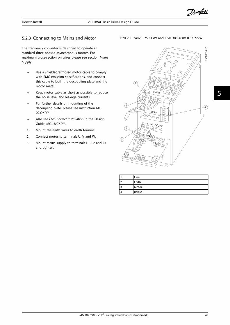
5.2.3 Connecting to Mains and Motor
The frequency converter is designed to operate allstandard three-phased asynchronous motors. Formaximum cross-section on wires please see section MainsSupply.
• Use a shielded/armored motor cable to complywith EMC emission specifications, and connectthis cable to both the decoupling plate and themotor metal.
• Keep motor cable as short as possible to reducethe noise level and leakage currents.
• For further details on mounting of thedecoupling plate, please see instruction MI.02.QX.YY
• Also see EMC-Correct Installation in the DesignGuide, MG.18.CX.YY.
1. Mount the earth wires to earth terminal.
2. Connect motor to terminals U, V and W.
3. Mount mains supply to terminals L1, L2 and L3and tighten.
IP20 200-240V 0.25-11kW and IP20 380-480V 0.37-22kW.
130B
B634
.10
1
2
2
3
4
Motor
U V W -DC+DC
MAINS
1 Line
2 Earth
3 Motor
4 Relays
How to Install VLT HVAC Basic Drive Design Guide
MG.18.C2.02 - VLT® is a registered Danfoss trademark 49
5 5

IP20 380-480V 30-45kW
1
95
99
L1 91 / L2 92 / L3 93
U 96 / V 97 / W 98
03 02 0106 05 04
2 3 4
130B
B762
.10
1 Line
2 Motor
3 Earth
4 Relays
IP20 380-480V 55-75kW
1 2
3
4
130B
B763
.10
1 Line
2 Relays
3 Earth
4 Motor
IP20 380-480V 90kW
130B
B764
.10
1
2
3
4
989796
99
95939291
L1 L1 L1
U V w
1 Line
2 Relays
3 Earth
4 Motor
5.2.4 Fuses
Branch circuit protectionIn order to protect the installation against electrical andfire hazard, all branch circuits in an installation, switchgear, machines etc., must be short-circuit and overcurrentprotected according to national/international regulations.
Short circuit protectionDanfoss recommends using the fuses mentioned in thefollowing tables to protect service personnel or otherequipment in case of an internal failure in the unit orshort-circuit on DC-link. The frequency converter providesfull short circuit protection in case of a short-circuit on themotor.
Overcurrent protectionProvide overload protection to avoid overheating of thecables in the installation. Overcurrent protection mustalways be carried out according to national regulations.Fuses must be designed for protection in a circuit capableof supplying a maximum of 100,000Arms (symmetrical),480V maximum.
How to Install VLT HVAC Basic Drive Design Guide
50 MG.18.C2.02 - VLT® is a registered Danfoss trademark
55

Non UL complianceIf UL/cUL is not to be complied with, Danfoss recommendsusing the fuses mentioned in the below table, which willensure compliance with IEC 61800-5-1:In case of malfunction, not following the fuse recommen-dation may result in damage to the frequency converter.
UL NonUL
Bussmann Bussmann Bussmann Bussmann Max.Fuse
PowerkW
Type RK5 Type RK1 Type J Type T TypegG
3 x 200-240V
0.25 FRS-R-10 KTN-R10 JKS-10 JJN-10 10
0.37 FRS-R-10 KTN-R10 JKS-10 JJN-10 10
0.75 FRS-R-10 KTN-R10 JKS-10 JJN-10 10
1.5 FRS-R-10 KTN-R10 JKS-10 JJN-10 10
2.2 FRS-R-15 KTN-R15 JKS-15 JJN-15 16
3.7 FRS-R-25 KTN-R25 JKS-25 JJN-25 25
5.5 FRS-R-50 KTN-R50 JKS-50 JJN-50 50
7.5 FRS-R-50 KTN-R50 JKS-50 JJN-50 50
11 FRS-R-80 KTN-R80 JKS-80 JJN-80 65
3 x 380-480V
0.37 FRS-R-10 KTS-R10 JKS-10 JJS-10 10
0.75 FRS-R-10 KTS-R10 JKS-10 JJS-10 10
1.5 FRS-R-10 KTS-R10 JKS-10 JJS-10 10
2.2 FRS-R-15 KTS-R15 JKS-15 JJS-15 16
3 FRS-R-15 KTS-R15 JKS-15 JJS-15 16
4 FRS-R-15 KTS-R15 JKS-15 JJS-15 16
5.5 FRS-R-25 KTS-R25 JKS-25 JJS-25 25
7.5 FRS-R-25 KTS-R25 JKS-25 JJS-25 25
11 FRS-R-50 KTS-R50 JKS-50 JJS-50 50
15 FRS-R-50 KTS-R50 JKS-50 JJS-50 50
18.5 FRS-R-80 KTS-R80 JKS-80 JJS-80 65
22 FRS-R-80 KTS-R80 JKS-80 JJS-80 65
30 FRS-R-80 KTS-R80 JKS-R80 JJS-R80 80
37 FRS-R-100 KTS-R100 JKS-R100 JJS-R100 100
45 FRS-R-125 KTS-R125 JKS-R125 JJS-R125 125
55 FRS-R-150 KTS-R150 JKS-R150 JJS-R150 150
75 FRS-R-200 KTS-R200 JKS-R200 JJS-R200 200
90 FRS-R-250 KTS-R250 JKS-R250 JJS-R250 250
5.2.5 EMC-Correct Electrical Installation
General points to be observed to ensure EMC-correctelectrical installation.
• Use only screened/armoured motor cables andscreened/armoured control cables.
• Connect the screen to earth at both ends.
• Avoid installation with twisted screen ends(pigtails), since this ruins the screening effect athigh frequencies. Use the cable clamps provide-dinstead.
• It is important to ensure good electrical contactfrom the installation plate through the installationscrews to the metal cabinet of the frequencyconverter.
• Use starwashers and galvanically conductiveinstallation plates.
• Do not use unscreened/unarmoured motor cablesin the installation cabinets.
How to Install VLT HVAC Basic Drive Design Guide
MG.18.C2.02 - VLT® is a registered Danfoss trademark 51
5 5

L1
L2
L3
PE
Min. 16 mm2
Equalizing cable
Control cables
All cable entries in
one side of panel
Earthing rail
Cable insula-tion stripped
Output con-tactor etc.
Motor cable
Motor, 3 phases and
PLC etc. Panel
Mains-supply
Min. 200mmbetween control cable, mains cable and between mains motor cable
PLC
Protective earthReinforced protective earth
130B
B761
.10
Illustration 5.1 EMC-correct Electrical Installation
For North America use metal conduits instead of shielded cables.
How to Install VLT HVAC Basic Drive Design Guide
52 MG.18.C2.02 - VLT® is a registered Danfoss trademark
55

5.2.6 Control Terminals
IP20 200-240V 0.25-11kW and IP20 380-480V 0.37-22kW:
130B
B622
.10
Illustration 5.2 Location of Control Terminals
1. Place a screwdriver behind the terminal cover toactivate snap.
2. Tilt the screwdriver outwards to open the cover.
IP20 380-480V 30-90kW.
130B
B624
.10
1. Place a screwdriver behind the terminal cover toactivate snap.
2. Tilt the screwdriver outwards to open the cover.
Digital input 18, 19 and 27 mode is set in 5-00 Digital InputMode (PNP is default value) and digital input 29 mode isset in 5-03 Digital Input 29 Mode (PNP is default value).
Control terminals:Illustration 5.3 shows all control terminals of the frequencyconverter. Applying Start (term. 18), connection betweenterminal 12-27 and an analog reference (term. 53 or 54and 55) make the frequency converter run.
18 19
12 20 55
27 29 42 45 50 53 54
DIG
I IN
DIG
I IN
DIG
I IN
DIG
I IN
61 68 69
NPCOM
M. G
ND
+24V
0/4-20mA A OUT / DIG OUT 0/4-20mA A OUT / DIG OUT
GND
GND
10V/20mA
IN
10V/20mA
IN
10V OU
T
130B
B625
.10BUS TER.
OFF ON
Illustration 5.3 Control Terminals
How to Install VLT HVAC Basic Drive Design Guide
MG.18.C2.02 - VLT® is a registered Danfoss trademark 53
5 5

6 How to Programme
6.1 Programming with MCT 10 Set-upSoftware
The frequency converter can be programmed from a PCvia RS-485 COM port by installing the MCT 10 Set-upSoftware. This software can either be ordered using codenumber 130B1000 or downloaded from the Danfoss Website: http://www.danfoss.com/BusinessAreas/DrivesSo-lutions/Softwaredownload/ Please refer to manual MG.10.RX.YY.
6.2 Local Control Panel (LCP)
The following instructions are valid for the FC 101 LCP. TheLCP is divided into four functional sections.
A. Alphanumeric display
B. Menu key
C. Navigation keys and indicator lights (LEDs)
D. Operation keys and indicator lights (LEDs)
Back
Com
1-20 Motor Power[2] 0.12kW-0.16HPSetup 1
A
B
1
12
13 14 15
11
11
10
9
8
7
6
54
3
2
C
D
Status MainMenu
QuickMenu
HandOn
OK
Menu
OffReset
AutoOn
Alarm
Warn
On
130B
B765
.10
A. Alpha Numeric DisplayThe LCD-display is back-lit with 2 alpha-numeric lines. Alldata is displayed on the LCP.
A number of information can be read from the display.
1 Parameter number and name.
2 Parameter value.
3 Set-up number shows the active set-up and the edit set-up. If the same set-up acts as both active and edit set-up,only that set-up number is shown (factory setting). Whenactive and edit set-up differ, both numbers are shown inthe display (Setup 12). The number flashing, indicates theedit set-up.
4 Motor direction is shown to the bottom left of the display– indicated by a small arrow pointing either clockwise orcounterclockwise.
5 The triangle indicates if the LCP is in status, quick menu ormain menu.
B. Menu KeyUse the menu key to select between status, quick menu ormain menu.
C. Navigation keys and indicator lights (LEDs)
6 Com led: Flashes when bus communication is communi-cating.
7 Green LED/On: Control section is working.
8 Yellow LED/Warn.: Indicates a warning.
9 Flashing Red LED/Alarm: Indicates an alarm.
10 [Back]: For moving to the previous step or layer in thenavigation structure
11 Arrows [] []: For maneuvering between parameter groups,
parameters and within parameters. Can also be used forsetting local reference.
12 [OK]: For selecting a parameter and for accepting changes toparameter settings
D. Operation keys and indicator lights (LEDs)
13 [Hand on]: Starts the motor and enables control of thefrequency converter via the LCP.
NOTEPlease note that terminal 27 Digital Input(5-12 Terminal 27 Digital Input) has coast inverse asdefault setting. This means that [Hand On] will notstart the motor if there is no 24V to terminal 27, soplease connect terminal 12 to terminal 27.
14 [Off/Reset]: Stops the motor (off). If in alarm mode thealarm will be reset.
15 [Auto on]: Frequency converter is controlled either viacontrol terminals or serial communication.
How to Programme VLT HVAC Basic Drive Design Guide
54 MG.18.C2.02 - VLT® is a registered Danfoss trademark
66

At power-upAt the first power-up the user is asked to choose preferredlanguage. Once selected this screen will never be shownagain in the following powerups, but language can still bechanged in 0-01 Language.
130B
B628
.10Select Language
[ 0 ] EnglishSetup 1
6.3 Menus
6.3.1 Status
When choosing the [Status] menu it is possible to choosebetween the following:
• Motor Frequency (Hz), par. 16-13;
• Motor Current (A), par. 16-14;
• Motor Speed Reference in Percentage (%), par.16-02;
• Feedback, par. 16-52;
• Motor Power (kW) (if 0-03 Regional Settings is setto [1] North America, Motor Power will be shownin the unit of hp instead of kW), par. 16-10 forkW, par. 16-11 for hp;
• Custom Readout par. 16-09;
6.3.2 Quick Menu
Allows quick setup of the frequency converter. The mostcommon VLT HVAC Basic Drive functions can beprogrammed here: The [Quick Menu] consists of:
• Wizard for open loop applications
• Closed loop set-up wizard
• Motor set-up
• Changes made
6.3.3 The FC 101 Start-up Wizard for OpenLoop Applications
The built in wizard menu guides the installer through theset up of the frequency converter in a clear and structuredmanner in order to setup an open loop application. Aopen loop application is here an application with a startsignal, analog reference (voltage or current) and optionallyalso relay signals (but no feed back signal from the processapplied).
FC+24V
DIG INDIG IN
DIG INDIG IN
COM DIG IN
A OUT / D OUTA OUT / D OUT
1819
2729
4255
505354
20
12
010203
040506
R2R1
+
-0-10V
Start
+10VA INA INCOM
130B
B674
.10
45
Reference
The wizard will initially be shown after power up until anyparameter has been changed. The wizard can always beaccessed again through the quick menu. Press [OK] to startthe wizard. If [BACK] is pressed, the FC 101 will return tothe status screen.
130B
B629
.10Press OK to start Wizard
Push Back to skip itSetup 1
How to Programme VLT HVAC Basic Drive Design Guide
MG.18.C2.02 - VLT® is a registered Danfoss trademark 55
6 6

Setup 1
Setup 1 Setup 1 Setup 1
Setup 1
Setup 1
Setup 1
Setup 1
Setup 1
Setup 1
Setup 1Setup 1
Setup 1
Setup 1
Setup 1
Setup 1
Setup 1
Setup 1
Setup 1
Setup 1
Setup 1
Setup 1
Setup 1
Setup 1
Setup 1
[0] Power kW/50 Hz
Set Motor Power1.10 kW
Set Motor Voltage0050 V
Set Motor Frequency0050 Hz
Set Motor Current04.66 A
Set Motor Nominal Speed 1420 RPM
Set Motor Speed Low Limit0016 Hz
Set Motor Speed High Limit0050 Hz
Set Ramp 1 Ramp Up Time0003 s
Set Ramp 1 Ramp Down Time0003 s
Active Flying start?[0] Disable
Select Terminal 53 Mode[0] Current
Set Terminal 53 Low Voltage0050 V
Set Terminal 53 High Voltage0220 V
Set Terminal 53 Low Current04.66A
Set Terminal 53 High Current13.30A
AMA Failed
0.0 Hz0.0 kW
Wizard completedPress OK to accept
Automatic Motor Adaption (AMA)[1] Enable
Auto Motor Tuning OKPress OK
Select Function Relay 2[0] No function
Select Function of Relay 1[0] No function
Set Maximum Reference0050 Hz
Set Minimum Reference0016 Hz
AMA running-----
OK
OK
Back
Status MainMenu
QuickMenu
HandOn
OK
Menu
OffReset
AutoOn
Alarm
Warn
On
AMA failed
Do AMA
Status Screen
The Wizard can always be
reentered via the Quick Menu!
(Do not AMA)
Current Voltage
Power Up Screen
At power up the user isasked to choose theprefered laguage.
Select language[1] English
0.0 Hz0.0 kW
Setup 1
Setup 1
Status MainMenu
QuickMenu
HandOn
OK
Menu
OffReset
AutoOn
Alarm
Warn
On
Press OK to start WizardPress Back to skip it
Setup 1
Status MainMenu
QuickMenu
HandOn
OK
Menu
OffReset
AutoOn
Alarm
Warn
On
The next screen will be
the Wizard screen.
Wizard Screen
AMA OK
5
7
8
9
10
11
1
2if
if
3
17
18
19
20
21
22
25
26
27
28
29
30
31
3435
36
32 33
23
24
130B
B993
.10
Back
Back
Back
Select Regional Settings
- the HVAC FC 101 Wizard starts
Setup 1200-240V/50Hz/DeltaGrid Type
4
Asynchronous Motor
How to Programme VLT HVAC Basic Drive Design Guide
56 MG.18.C2.02 - VLT® is a registered Danfoss trademark
66

The FC 101 Start-up Wizard for Open Loop ApplicationsNo & Name Range Default Function0-03 Regional Settings [0] International
[1] US0
0-06 Grid Type 0] 200-240V/50Hz/IT-grid[1] 200-240V/50Hz/Delta[2] 200-240V/50Hz[10] 380-440V/50Hz/IT-grid[11] 380-440V/50Hz/Delta[12] 380-440V/50Hz[20] 440-480V/50Hz/IT-grid[21] 440-480V/50Hz/Delta[22] 440-480V/50Hz[30] 525-600V/50Hz/IT-grid[31] 525-600V/50Hz/Delta[32] 525-600V/50Hz[100] 200-240V/60Hz/IT-grid[101] 200-240V/60Hz/Delta[102] 200-240V/60Hz[110] 380-440V/60Hz/IT-grid[111] 380-440V/60Hz/Delta[112] 380-440V/60Hz[120] 440-480V/60Hz/IT-grid[121] 440-480V/60Hz/Delta[122] 440-480V/60Hz[130] 525-600V/60Hz/IT-grid[131] 525-600V/60Hz/Delta[132] 525-600V/60Hz
Size related Select operating mode for restart uponreconnection of the drive to mains voltage afterpower down
1-20 Motor Power 0.12-110kW/0.16-150hp Size related Enter motor power from nameplate data
1-22 Motor Voltage 50.0 - 1000.0V Size related Enter motor voltage from nameplate data
1-23 Motor Frequency 20.0 - 400.0Hz Size related Enter motor frequency from nameplate data
1-24 Motor Current 0.01 - 10000.00A Size related Enter motor current from nameplate data
1-25 Motor NominalSpeed
100.0 - 9999.0 RPM Size related Enter motor nominal speed from nameplate data
4-12 Motor Speed LowLimit [Hz]
0.0 - 400 Hz 0 Hz Enter the minimum limit for low speed
4-14 Motor Speed HighLimit [Hz]
0.0 - 400 Hz 65 Hz Enter the maximum limit for high speed
3-41 Ramp 1 Ramp upTime
0.05 - 3600.0 s Size related Ramp up time from 0 to rated 1-23 MotorFrequency
3-42 Ramp 1 RampDown Time
0.05 - 3600.0 s Size related Ramp down time from rated 1-23 Motor Frequencyto 0
1-73 Flying Start [0] Disabled[1] Enabled
0 Select Enable to enable the frequency converter tocatch a spinning motor i.e. fan applications
6-19 Terminal 53 mode [0] Current[1] Voltage
1 Select if terminal 53 is used for current- or voltageinput
6-10 Terminal 53 LowVoltage
0-10V 0.07V Enter the voltage that corresponds to the lowreference value
6-11 Terminal 53 HighVoltage
0-10V 10V Enter the voltage that corresponds to the highreference value
6-12 Terminal 53 LowCurrent
0-20mA 4 Enter the current that corresponds to the lowreference value
6-13 Terminal 53 HighCurrent
0-20mA 20 Enter the current that corresponds to the highreference value
3-02 Minimum Reference -4999-4999 0 The minimum reference is the lowest valueobtainable by summing all references
How to Programme VLT HVAC Basic Drive Design Guide
MG.18.C2.02 - VLT® is a registered Danfoss trademark 57
6 6

No & Name Range Default Function3-03 Maximum Reference -4999-4999 50 The maximum reference is the lowest obtainable
by summing all references
5-40 Function Relay [0]Function relay
See 5-40 Function Relay Alarm Select the function to control output relay 1
5-40 Function Relay [1]Function relay
See 5-40 Function Relay Drive running Select the function to control output relay 2
1-29 Automatic MotorAdaption (AMA)
See 1-29 Automatic Motor Adaption(AMA)
Off Performing an AMA optimizes motor performance
How to Programme VLT HVAC Basic Drive Design Guide
58 MG.18.C2.02 - VLT® is a registered Danfoss trademark
66

Closed Loop Set-up Wizard
6-29 Terminal 54 Mode[1] Voltage mode
6-25 Terminal 54 High Ref./Feedb. Value
0050 Hz
20-94 PI Integral Time9999 s
Current Voltage
This dialog is forced to be set to [2] Analog in 54
24
25
26
27
28
29
30
31
20-00 Feedback1 source[2] Analog in 54
3-10 Preset reference [0][1] 0
3-03 Max Reference[1] 50
3-02 Min Reference[1] 0
Asynchronous Motor
1-73 Flying Start [0] No
1-22 Motor Voltage0050 V
1-24 Motor current04.66 A
1-25 Motor nominal speed1420 RPM
3-41 Ramp 1 ramp-up time0003 s
3-42 Ramp1 ramp-down time0003 s
3
4
5
6
7
13
14
15
17
18
18a
20
21
22
23
32
33
34
35
36
37
0-03 Regional Settings[0] International
4-12 Motor speed low limit0016 Hz
4-14 Motor speed high limit0050 Hz
1
130B
B631
.11
1-20 Motor Power1.10 kW
1-23 Motor frequency0050 Hz
6-22 Terminal 54 Low Current 4 mA
6-24 Terminal 54 Low Ref./Feedb. Value0016 Hz
6-23 Terminal 54 High Current20 mA
6-25 Terminal 54 High Ref./Feedb. Value50
0,01 s
20-81 PI Normal/Inverse Control[0] Normal
20-83 PI Start Speed0 Hz
20-93 PI Proportional Gain0,01 s
1-29 Automatic Motor Adaption[1] Enable
6-20 Terminal 54 Low Voltage0,07 V
6-24 Terminal 54 Low Ref./Feedb. Value
0 Hz
6-21 Terminal 54 High Voltage10 V
6-26 Terminal 54 Filter time constant
3-10 Preset reference is the set-point
Please note that Terminal 27 Digital Input (par. 5-12) has coast inverse as default setting. This means that AMA can not be performed if there is no 24V to terminal27 so please connect terminal 12 to terminal 27.
0-01 Configuration Mode[0] Open Loop2
How to Programme VLT HVAC Basic Drive Design Guide
MG.18.C2.02 - VLT® is a registered Danfoss trademark 59
6 6
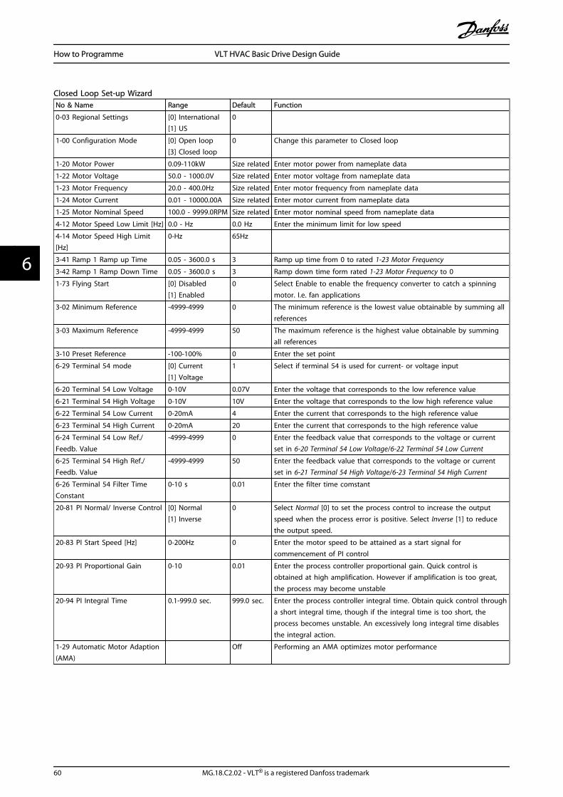
Closed Loop Set-up WizardNo & Name Range Default Function
0-03 Regional Settings [0] International[1] US
0
1-00 Configuration Mode [0] Open loop[3] Closed loop
0 Change this parameter to Closed loop
1-20 Motor Power 0.09-110kW Size related Enter motor power from nameplate data
1-22 Motor Voltage 50.0 - 1000.0V Size related Enter motor voltage from nameplate data
1-23 Motor Frequency 20.0 - 400.0Hz Size related Enter motor frequency from nameplate data
1-24 Motor Current 0.01 - 10000.00A Size related Enter motor current from nameplate data
1-25 Motor Nominal Speed 100.0 - 9999.0RPM Size related Enter motor nominal speed from nameplate data
4-12 Motor Speed Low Limit [Hz] 0.0 - Hz 0.0 Hz Enter the minimum limit for low speed
4-14 Motor Speed High Limit[Hz]
0-Hz 65Hz
3-41 Ramp 1 Ramp up Time 0.05 - 3600.0 s 3 Ramp up time from 0 to rated 1-23 Motor Frequency
3-42 Ramp 1 Ramp Down Time 0.05 - 3600.0 s 3 Ramp down time form rated 1-23 Motor Frequency to 0
1-73 Flying Start [0] Disabled[1] Enabled
0 Select Enable to enable the frequency converter to catch a spinningmotor. I.e. fan applications
3-02 Minimum Reference -4999-4999 0 The minimum reference is the lowest value obtainable by summing allreferences
3-03 Maximum Reference -4999-4999 50 The maximum reference is the highest value obtainable by summingall references
3-10 Preset Reference -100-100% 0 Enter the set point
6-29 Terminal 54 mode [0] Current[1] Voltage
1 Select if terminal 54 is used for current- or voltage input
6-20 Terminal 54 Low Voltage 0-10V 0.07V Enter the voltage that corresponds to the low reference value
6-21 Terminal 54 High Voltage 0-10V 10V Enter the voltage that corresponds to the low high reference value
6-22 Terminal 54 Low Current 0-20mA 4 Enter the current that corresponds to the high reference value
6-23 Terminal 54 High Current 0-20mA 20 Enter the current that corresponds to the high reference value
6-24 Terminal 54 Low Ref./Feedb. Value
-4999-4999 0 Enter the feedback value that corresponds to the voltage or currentset in 6-20 Terminal 54 Low Voltage/6-22 Terminal 54 Low Current
6-25 Terminal 54 High Ref./Feedb. Value
-4999-4999 50 Enter the feedback value that corresponds to the voltage or currentset in 6-21 Terminal 54 High Voltage/6-23 Terminal 54 High Current
6-26 Terminal 54 Filter TimeConstant
0-10 s 0.01 Enter the filter time comstant
20-81 PI Normal/ Inverse Control [0] Normal[1] Inverse
0 Select Normal [0] to set the process control to increase the outputspeed when the process error is positive. Select Inverse [1] to reducethe output speed.
20-83 PI Start Speed [Hz] 0-200Hz 0 Enter the motor speed to be attained as a start signal forcommencement of PI control
20-93 PI Proportional Gain 0-10 0.01 Enter the process controller proportional gain. Quick control isobtained at high amplification. However if amplification is too great,the process may become unstable
20-94 PI Integral Time 0.1-999.0 sec. 999.0 sec. Enter the process controller integral time. Obtain quick control througha short integral time, though if the integral time is too short, theprocess becomes unstable. An excessively long integral time disablesthe integral action.
1-29 Automatic Motor Adaption(AMA)
Off Performing an AMA optimizes motor performance
How to Programme VLT HVAC Basic Drive Design Guide
60 MG.18.C2.02 - VLT® is a registered Danfoss trademark
66

Motor Set-upThe Quick Menu Motor Set-up guides through the neededmotor parameters.
No & Name Range Default Function
0-03 RegionalSettings
[0] Interna-tional[1] US
0
1-20 MotorPowerr
0.12-110kW/0.16-150hp
Size related Enter motorpower fromnameplate data
1-22 MotorVoltage
50.0 - 1000.0V Size related Enter motorvoltage fromnameplate data
1-23 MotorFrequency
20.0 - 400.0Hz Size related Enter motorfrequency fromnameplate data
1-24 MotorCurrent
0.01 -10000.00A
Size related Enter motorcurrent fromnameplate data
1-25 MotorNominalSpeed
100.0 - 9999.0RPM
Size related Enter motornominal speedfrom nameplatedata
4-12 MotorSpeed LowLimit [Hz]
0.0 - 400Hz 0.0Hz Enter theminimum limitfor low speed
4-14 MotorSpeed HighLimit [Hz]
0.0 - 400HZ 65 Enter themaximum limitfor high speed
3-41 Ramp 1Ramp up Time
0.05 - 3600.0 s Size related Ramp up timefrom 0 to rated1-23 MotorFrequency
3-42 Ramp 1Ramp DownTime
0.05 - 3600.0 s Size related Ramp down timefrom rated1-23 MotorFrequency to 0
1-73 FlyingStart
[0] Disabled[1] Enabled
0 Select Enable toenable thefrequencyconverter tocatch a spinningmotor
Changes MadeChanges Made lists all parameters changed since factorysetting. Only the changed parameters in current edit-setupare listed in changes made.
If the parameter's value is changed back to factorysetting's value from another different value, the parameterwill NOT be listed in Changes Made.
1. Press [MENU] key to enter the Quick Menu untilindicator in display is placed above Quick Menu.
2. Press [] [] to select either FC 101 wizard,closed loop setup, motor setup or changes made,then press [OK].
3. Press [] [] to browse through the parametersin the Quick Menu.
4. Press [OK] to select a parameter.
5. Press [] [] to change the value of a parametersetting.
6. Press [OK] to accept the change.
7. Press either [Back] twice to enter “Status”, orpress [Menu] once to enter “Main Menu”.
6.3.4 Main Menu
[Main Menu] is used for programming all parameters. TheMain Menu parameters can be accessed immediatelyunless a password has been created via 0-60 Main MenuPassword. For the majority of VLT HVAC Basic Driveapplications it is not necessary to access the Main Menuparameters but instead the Quick Menu provides thesimplest and quickest access to the typical requiredparameters.
The Main Menu accesses all parameters.
1. Press [MENU] key until indicator in display isplaced above “Main Menu”.
2. Use [] [] to browse through the parametergroups.
3. Press [OK] to select a parameter group.
4. Use [] [] to browse through the parameters inthe specific group.
5. Press [OK] to select the parameter.
6. Use [] [] to set/change the parameter value.
[BACK] is used to go one level back.
How to Programme VLT HVAC Basic Drive Design Guide
MG.18.C2.02 - VLT® is a registered Danfoss trademark 61
6 6
6.4 Quick Transfer of Parameter Settingsbetween Multiple Frequency Converters
Once the set-up of a frequency converter is complete,Danfoss recommends that you store the data in the LCP oron a PC via MCT 10 Set-up Software tool.
Data storage in LCP.
1. Go to 0-50 LCP Copy
2. Press the [OK] key
3. Select “All to LCP”
4. Press the [OK] key
WARNINGStop the motor before performing this operation.
You can now connect the LCP to another frequencyconverter and copy the parameter settings to thisfrequency converter as well.
Data transfer from LCP to frequency converter:
1. Go to 0-50 LCP Copy
2. Press the [OK] key
3. Select “All from LCP”
4. Press the [OK] key
NOTEStop the motor before performing this operation.
6.5 Read-out and Programming of IndexedParameters
Use 3-10 Preset Reference as an example.Choose the parameter, press [OK], and use the up/downnavigation keys to scroll through the indexed values. Tochange the parameter value, select the indexed value andpress [OK]. Change the value by using the up/down keys.Press [OK] to accept the new setting. Press [CANCEL] toabort. Press [Back] to leave the parameter.
6.6 Initialise the Frequency Converter toDefault Settings in two Ways
Recommended initialisation (via 14-22 Operation Mode)
1. Select 14-22 Operation Mode.
2. Press [OK].
3. Select Initialisation and Press [OK].
4. Cut off the mains supply and wait until thedisplay turns off.
5. Reconnect the mains supply - the frequencyconverter is now reset. Except the followingparameters.
8-30 Protocol
8-31 Address
8-32 Baud Rate
8-33 Parity / Stop Bits
8-35 Minimum Response Delay
8-36 Maximum Response Delay
8-37 Maximum Inter-char delay
8-70 BACnet Device Instance
8-72 MS/TP Max Masters
8-73 MS/TP Max Info Frames
8-74 "I am" Service
8-75 Intialisation Password
15-00 Operating Hours to 15-05 Over Volt's
15-03 Power Up's
15-04 Over Temp's
15-05 Over Volt's
15-30 Alarm Log: Error Code
15-4* Drive identification parameters
1-06 Clockwise Direction
How to Programme VLT HVAC Basic Drive Design Guide
62 MG.18.C2.02 - VLT® is a registered Danfoss trademark
66

Two finger initialization:1. Power off the frequency converter.
2. Press [OK] and [MENU].
3. Power up the frequency converter while stillpressing the keys above for 10 sec.
4. The frequency converter is now reset, except thefollowing parameters:
15-00 Operating Hours
15-03 Power Up's
15-04 Over Temp's
15-05 Over Volt's
15-4* Drive identification parameters
Initialisation of parameters is confirmed by AL80 in thedisplay after the power cycle.
How to Programme VLT HVAC Basic Drive Design Guide
MG.18.C2.02 - VLT® is a registered Danfoss trademark 63
6 6

7 RS-485 Installation and Set-up
7.1.1 Overview
RS-485 is a two-wire bus interface compatible with multi-drop network topology, i.e. nodes can be connected as abus, or via drop cables from a common trunk line. A totalof 32 nodes can be connected to one network segment.Repeaters divide network segments. Please note that eachrepeater functions as a node within the segment in whichit is installed. Each node connected within a given networkmust have a unique node address, across all segments.Terminate each segment at both ends, using either thetermination switch (S801) of the frequency converters or abiased termination resistor network. Always use screenedtwisted pair (STP) cable for bus cabling, and always followgood common installation practice.Low-impedance earth connection of the screen at everynode is important, including at high frequencies. Thus,connect a large surface of the screen to earth, for examplewith a cable clamp or a conductive cable gland. It may benecessary to apply potential-equalizing cables to maintainthe same earth potential throughout the network. Partic-ularly in installations with long cables.To prevent impedance mismatch, always use the sametype of cable throughout the entire network. Whenconnecting a motor to the frequency converter, always usescreened motor cable.
Cable: Screened twisted pair (STP)
Impedance: 120ΩCable length: Max. 1200m (including drop lines)
Max. 500m station-to-station
7.1.2 Network Connection
Connect the frequency converter to the RS-485 networkas follows (see also diagram):
1. Connect signal wires to terminal 68 (P+) andterminal 69 (N-) on the main control board of thefrequency converter.
2. Connect the cable screen to the cable clamps.
NOTEScreened, twisted-pair cables are recommended in order toreduce noise between conductors.
61 68 69
NPCOM
M. G
ND
130B
B795
.10
7.1.3 Frequency Converter Hardware Set-up
Use the terminator dip switch on the main control boardof the frequency converter to terminate the RS-485 bus.
130B
B966
.10
Illustration 7.1 Terminator Switch Factory Setting
The factory setting for the dip switch is OFF.
RS-485 Installation and Set... VLT HVAC Basic Drive Design Guide
64 MG.18.C2.02 - VLT® is a registered Danfoss trademark
77

7.1.4 Frequency Converter ParameterSettings for Modbus Communication
The following parameters apply to the RS-485 interface(FC-port):
Parameter Function
8-30 Protocol Select the application protocol to run onthe RS-485 interface
8-31 Address Set the node address. Note: The addressrange depends on the protocol selected in8-30 Protocol
8-32 Baud Rate Set the baud rate. Note: The default baudrate depends on the protocol selected in8-30 Protocol
8-33 Parity / StopBits
Set the parity and number of stop bits.Note: The default selection depends on theprotocol selected in 8-30 Protocol
8-35 MinimumResponse Delay
Specify a minimum delay time betweenreceiving a request and transmitting aresponse. This function is for overcomingmodem turnaround delays.
8-36 MaximumResponse Delay
Specify a maximum delay time betweentransmitting a request and receiving aresponse.
8-37 MaximumInter-char delay
If transmission is interrupted, specify amaximum delay time between two receivedbytes to ensure time-out.
7.1.5 EMC Precautions
To achieve interference-free operation of the RS-485network, Danfoss recommends the following EMCprecautions.
Relevant national and local regulations, for exampleregarding protective earth connection, must be observed.To avoid coupling of high frequency noise between thecables, the RS-485 communication cable must be keptaway from motor and brake resistor cables. Normally adistance of 200mm (8 inches) is sufficient, but Danfossrecommends keeping the greatest possible distancebetween the cables. Especially where cables run in parallelover long distances. When crossing is unavoidable, theRS-485 cable must cross motor and brake resistor cables atan angle of 90°.
7.2 FC Protocol Overview
The FC protocol, also referred to as FC bus or Standardbus, is the Danfoss standard fieldbus. It defines an accesstechnique according to the master-slave principle forcommunications via a serial bus.One master and a maximum of 126 slaves can beconnected to the bus. The master selects the individualslaves via an address character in the telegram. A slaveitself can never transmit without first being requested todo so, and direct message transfer between the individualslaves is not possible. Communications occur in the half-duplex mode.The master function cannot be transferred to another node(single-master system).
The physical layer is RS-485, thus utilizing the RS-485 portbuilt into the frequency converter. The FC protocolsupports different telegram formats:
• A short format of 8 bytes for process data.
• A long format of 16 bytes that also includes aparameter channel.
• A format used for texts.
7.2.1 FC with Modbus RTU
The FC protocol provides access to the Control Word andBus Reference of the frequency converter.
The Control Word allows the Modbus master to controlseveral important functions of the frequency converter.
• Start
• Stop of the frequency converter in various ways:
• Coast stop
• Quick stop
• DC Brake stop
• Normal (ramp) stop
• Reset after a fault trip
• Run at various preset speeds
• Run in reverse
• Change of the active set-up
• Control of the 2 relays built into the frequencyconverter
The Bus Reference is commonly used for speed control. Itis also possible to access the parameters, read their values,and where possible, write values to them. This permits arange of control options, including controlling the setpoint
RS-485 Installation and Set... VLT HVAC Basic Drive Design Guide
MG.18.C2.02 - VLT® is a registered Danfoss trademark 65
7 7

of the frequency converter when its internal PI controller isused.
7.3 Network Configuration
7.3.1 Frequency Converter Set-up
Set the following parameters to enable the FC protocol forthe frequency converter.
Parameter Setting
8-30 Protocol FC
8-31 Address 1 - 126
8-32 Baud Rate 2400 - 115200
8-33 Parity / StopBits
Even parity, 1 stop bit (default)
7.4 FC Protocol Message Framing Structure
7.4.1 Content of a Character (byte)
Each character transferred begins with a start bit. Then 8data bits are transferred, corresponding to a byte. Eachcharacter is secured via a parity bit. This bit is set at "1"when it reaches parity. Parity is when there is an equalnumber of 1s in the 8 data bits and the parity bit in total.
A stop bit completes a character, thus consisting of 11 bitsin all.
0 1 32 4 5 6 7
195N
A03
6.10
Startbit
Even StopParity bit
7.4.2 Telegram Structure
Each telegram has the following structure:
1. Start character (STX)=02 Hex
2. A byte denoting the telegram length (LGE)
3. A byte denoting the frequency converter address(ADR)
A number of data bytes (variable, depending on the typeof telegram) follows.
A data control byte (BCC) completes the telegram.
STX LGE ADR DATA BCC
195N
A09
9.10
7.4.3 Length (LGE)
The length is the number of data bytes plus the address byte ADR and the data control byte BCC.
The length of telegrams with 4 data bytes is LGE = 4 + 1 + 1 = 6 bytesThe length of telegrams with 12 data bytes is LGE = 12 + 1 + 1 = 14 bytesThe length of telegrams containing texts is 101)+n bytes
1) The 10 represents the fixed characters, while the “n’” is variable (depending on the length of the text).
7.4.4 Frequency Converter Address (ADR)
Address format 1-126Bit 7 = 1 (address format 1-126 active)
Bit 0-6 = frequency converter address 1-126
Bit 0-6 = 0 Broadcast
The slave returns the address byte unchanged to the master in the response telegram.
7.4.5 Data Control Byte (BCC)
The checksum is calculated as an XOR-function. Before the first byte in the telegram is received, the Calculated Checksum is0.
7.4.6 The Data Field
The structure of data blocks depends on the type of . There are three types, and the type applies for both control telegrams(master=>slave) and response telegrams (slave=>master).
RS-485 Installation and Set... VLT HVAC Basic Drive Design Guide
66 MG.18.C2.02 - VLT® is a registered Danfoss trademark
77

The 3 types of are:
Process block (PCD)The PCD is made up of a data block of 4 bytes (2 words) and contains:
- Control word and reference value (from master to slave)
- Status word and present output frequency (from slave to master)
ADRLGESTX PCD1 PCD2 BCC
130B
A26
9.10
Parameter blockThe parameter block is used to transfer parameters between master and slave. The data block is made up of 12 bytes (6words) and also contains the process block.
PKE INDADRLGESTX PCD1 PCD2 BCC
130B
A27
1.10
PWEhigh PWElow
Text blockThe text block is used to read or write texts via the data block.
PKE IND
130B
A27
0.10
ADRLGESTX PCD1 PCD2 BCCCh1 Ch2 Chn
7.4.7 The PKE Field
The PKE field contains two subfields: Parameter commandand response (AK) and Parameter number (PNU):
15 14 13 12 11 10 9 8 7 6 5 4 3 2 1 0
130B
B918
.10
PKE IND PWEhigh PWElow
AK PNU
Para
met
er
com
man
ds
and
rep
lies
Para
met
ernu
mb
er
Bits no. 12-15 transfer parameter commands from masterto slave and return processed slave responses to themaster.
Parameter commands master ⇒ slave
Bit no. Parameter command
15 14 13 12
0 0 0 0 No command
0 0 0 1 Read parameter value
0 0 1 0 Write parameter value in RAM (word)
0 0 1 1 Write parameter value in RAM (doubleword)
1 1 0 1 Write parameter value in RAM andEEprom (double word)
1 1 1 0 Write parameter value in RAM andEEprom (word)
1 1 1 1 Read text
Response slave ⇒master
Bit no. Response
15 14 13 12
0 0 0 0 No response
0 0 0 1 Parameter value transferred (word)
0 0 1 0 Parameter value transferred (doubleword)
0 1 1 1 Command cannot be performed
1 1 1 1 text transferred
If the command cannot be performed, the slave sends thisresponse:0111 Command cannot be performed
RS-485 Installation and Set... VLT HVAC Basic Drive Design Guide
MG.18.C2.02 - VLT® is a registered Danfoss trademark 67
7 7
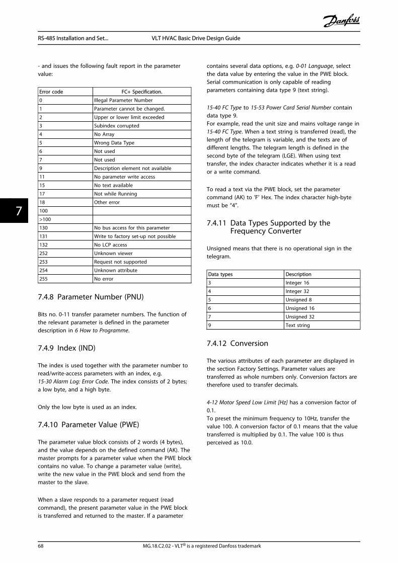
- and issues the following fault report in the parametervalue:
Error code FC+ Specification.
0 Illegal Parameter Number
1 Parameter cannot be changed.
2 Upper or lower limit exceeded
3 Subindex corrupted
4 No Array
5 Wrong Data Type
6 Not used
7 Not used
9 Description element not available
11 No parameter write access
15 No text available
17 Not while Running
18 Other error
100
>100
130 No bus access for this parameter
131 Write to factory set-up not possible
132 No LCP access
252 Unknown viewer
253 Request not supported
254 Unknown attribute
255 No error
7.4.8 Parameter Number (PNU)
Bits no. 0-11 transfer parameter numbers. The function ofthe relevant parameter is defined in the parameterdescription in 6 How to Programme.
7.4.9 Index (IND)
The index is used together with the parameter number toread/write-access parameters with an index, e.g.15-30 Alarm Log: Error Code. The index consists of 2 bytes;a low byte, and a high byte.
Only the low byte is used as an index.
7.4.10 Parameter Value (PWE)
The parameter value block consists of 2 words (4 bytes),and the value depends on the defined command (AK). Themaster prompts for a parameter value when the PWE blockcontains no value. To change a parameter value (write),write the new value in the PWE block and send from themaster to the slave.
When a slave responds to a parameter request (readcommand), the present parameter value in the PWE blockis transferred and returned to the master. If a parameter
contains several data options, e.g. 0-01 Language, selectthe data value by entering the value in the PWE block.Serial communication is only capable of readingparameters containing data type 9 (text string).
15-40 FC Type to 15-53 Power Card Serial Number containdata type 9.For example, read the unit size and mains voltage range in15-40 FC Type. When a text string is transferred (read), thelength of the telegram is variable, and the texts are ofdifferent lengths. The telegram length is defined in thesecond byte of the telegram (LGE). When using texttransfer, the index character indicates whether it is a reador a write command.
To read a text via the PWE block, set the parametercommand (AK) to ’F’ Hex. The index character high-bytemust be “4”.
7.4.11 Data Types Supported by theFrequency Converter
Unsigned means that there is no operational sign in thetelegram.
Data types Description
3 Integer 16
4 Integer 32
5 Unsigned 8
6 Unsigned 16
7 Unsigned 32
9 Text string
7.4.12 Conversion
The various attributes of each parameter are displayed inthe section Factory Settings. Parameter values aretransferred as whole numbers only. Conversion factors aretherefore used to transfer decimals.
4-12 Motor Speed Low Limit [Hz] has a conversion factor of0.1.To preset the minimum frequency to 10Hz, transfer thevalue 100. A conversion factor of 0.1 means that the valuetransferred is multiplied by 0.1. The value 100 is thusperceived as 10.0.
RS-485 Installation and Set... VLT HVAC Basic Drive Design Guide
68 MG.18.C2.02 - VLT® is a registered Danfoss trademark
77

Conversion index Conversion factor
74 0.1
2 100
1 10
0 1
-1 0.1
-2 0.01
-3 0.001
-4 0.0001
-5 0.00001
7.4.13 Process Words (PCD)
The block of process words is divided into two blocks of16 bits, which always occur in the defined sequence.
PCD 1 PCD 2
Control (master⇒ slave Control word) Reference-value
Control (slave ⇒ master) Status word Present outputfrequency
7.5 Examples
7.5.1 Writing a Parameter Value
Change 4-14 Motor Speed High Limit [Hz] to 100Hz.Write the data in EEPROM.
PKE = E19E Hex - Write single word in 4-14 Motor SpeedHigh Limit [Hz]:
IND = 0000 Hex
PWEHIGH = 0000 Hex
PWELOW = 03E8 Hex
Data value 1000, corresponding to 100Hz, see7.3.12 Conversion.
The telegram looks like this:
E19E H
PKE IND PWE high PWE low
0000 H 0000 H 03E8 H
130B
A09
2.10
Note: 4-14 Motor Speed High Limit [Hz] is a single word, andthe parameter command for write in EEPROM is “E”.Parameter number 4-14 is 19E in hexadecimal.
The response from the slave to the master is:
119E H
PKE IND PWE high PWE low
0000 H 0000 H 03E8 H
130B
A09
3.10
7.5.2 Reading a Parameter Value
Read the value in 3-41 Ramp 1 Ramp up Time
PKE = 1155 Hex - Read parameter value in 3-41 Ramp 1Ramp up TimeIND = 0000 HexPWEHIGH = 0000 HexPWELOW = 0000 Hex
1155 H
PKE IND PWE high PWE low
0000 H 0000 H 0000 H
130B
A09
4.10
If the value in 3-41 Ramp 1 Ramp up Time is 10 s, theresponse from the slave to the master is:
130B
A26
7.10
1155 H
PKE IND
0000 H 0000 H 03E8 H
PWE high PWE low
3E8 Hex corresponds to 1000 decimal. The conversionindex for 3-41 Ramp 1 Ramp up Time is -2, i.e. 0.01.3-41 Ramp 1 Ramp up Time is of the type Unsigned 32.
7.6 Modbus RTU Overview
7.6.1 Assumptions
Danfoss assumes that the installed controller supports theinterfaces in this document, and strictly observe allrequirements and limitations stipulated in the controllerand frequency converter.
7.6.2 What the User Should Already Know
The Modbus RTU (Remote Terminal Unit) is designed tocommunicate with any controller that supports theinterfaces defined in this document. It is assumed that theuser has full knowledge of the capabilities and limitationsof the controller.
7.6.3 Modbus RTU Overview
Regardless of the type of physical communicationnetworks, the Modbus RTU Overview describes the processa controller uses to request access to another device. Thisprocess includes how the Modbus RTU responds to
RS-485 Installation and Set... VLT HVAC Basic Drive Design Guide
MG.18.C2.02 - VLT® is a registered Danfoss trademark 69
7 7
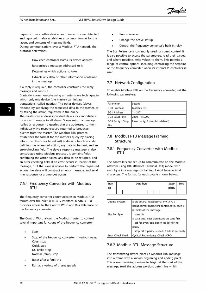
requests from another device, and how errors are detectedand reported. It also establishes a common format for thelayout and contents of message fields.During communications over a Modbus RTU network, theprotocol determines:
How each controller learns its device address
Recognizes a message addressed to it
Determines which actions to take
Extracts any data or other information containedin the message
If a reply is required, the controller constructs the replymessage and sends it.Controllers communicate using a master-slave technique inwhich only one device (the master) can initiatetransactions (called queries). The other devices (slaves)respond by supplying the requested data to the master, orby taking the action requested in the query.The master can address individual slaves, or can initiate abroadcast message to all slaves. Slaves return a message(called a response) to queries that are addressed to themindividually. No responses are returned to broadcastqueries from the master. The Modbus RTU protocolestablishes the format for the master’s query by placinginto it the device (or broadcast) address, a function codedefining the requested action, any data to be sent, and anerror-checking field. The slave’s response message is alsoconstructed using Modbus protocol. It contains fieldsconfirming the action taken, any data to be returned, andan error-checking field. If an error occurs in receipt of themessage, or if the slave is unable to perform the requestedaction, the slave will construct an error message, and sendit in response, or a time-out occurs.
7.6.4 Frequency Converter with ModbusRTU
The frequency converter communicates in Modbus RTUformat over the built-in RS-485 interface. Modbus RTUprovides access to the Control Word and Bus Reference ofthe frequency converter.
The Control Word allows the Modbus master to controlseveral important functions of the frequency converter:
• Start
• Stop of the frequency converter in various ways:Coast stopQuick stopDC Brake stopNormal (ramp) stop
• Reset after a fault trip
• Run at a variety of preset speeds
• Run in reverse
• Change the active set-up
• Control the frequency converter’s built-in relay
The Bus Reference is commonly used for speed control. Itis also possible to access the parameters, read their values,and where possible, write values to them. This permits arange of control options, including controlling the setpointof the frequency converter when its internal PI controller isused.
7.7 Network Configuration
To enable Modbus RTU on the frequency converter, set thefollowing parameters:
Parameter Setting
8-30 Protocol Modbus RTU
8-31 Address 1 - 247
8-32 Baud Rate 2400 - 115200
8-33 Parity / StopBits
Even parity, 1 stop bit (default)
7.8 Modbus RTU Message FramingStructure
7.8.1 Frequency Converter with ModbusRTU
The controllers are set up to communicate on the Modbusnetwork using RTU (Remote Terminal Unit) mode, witheach byte in a message containing 2 4-bit hexadecimalcharacters. The format for each byte is shown below.
Startbit
Data byte Stop/parity
Stop
Coding System 8-bit binary, hexadecimal 0-9, A-F. 2hexadecimal characters contained in each 8-bit field of the message
Bits Per Byte 1 start bit8 data bits, least significant bit sent first1 bit for even/odd parity; no bit for noparity1 stop bit if parity is used; 2 bits if no parity
Error Check Field Cyclical Redundancy Check (CRC)
7.8.2 Modbus RTU Message Structure
The transmitting device places a Modbus RTU messageinto a frame with a known beginning and ending point.This allows receiving devices to begin at the start of themessage, read the address portion, determine which
RS-485 Installation and Set... VLT HVAC Basic Drive Design Guide
70 MG.18.C2.02 - VLT® is a registered Danfoss trademark
77
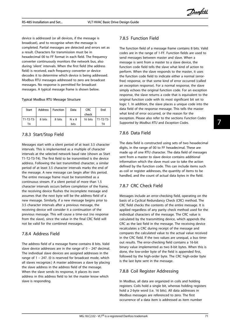
device is addressed (or all devices, if the message isbroadcast), and to recognise when the message iscompleted. Partial messages are detected and errors set asa result. Characters for transmission must be inhexadecimal 00 to FF format in each field. The frequencyconverter continuously monitors the network bus, alsoduring ‘silent’ intervals. When the first field (the addressfield) is received, each frequency converter or devicedecodes it to determine which device is being addressed.Modbus RTU messages addressed to zero are broadcastmessages. No response is permitted for broadcastmessages. A typical message frame is shown below.
Typical Modbus RTU Message Structure
Start Address Function Data CRCcheck
End
T1-T2-T3-T4
8 bits 8 bits N x 8bits
16 bits T1-T2-T3-T4
7.8.3 Start/Stop Field
Messages start with a silent period of at least 3.5 characterintervals. This is implemented as a multiple of characterintervals at the selected network baud rate (shown as StartT1-T2-T3-T4). The first field to be transmitted is the deviceaddress. Following the last transmitted character, a similarperiod of at least 3.5 character intervals marks the end ofthe message. A new message can begin after this period.The entire message frame must be transmitted as acontinuous stream. If a silent period of more than 1.5character intervals occurs before completion of the frame,the receiving device flushes the incomplete message andassumes that the next byte will be the address field of anew message. Similarly, if a new message begins prior to3.5 character intervals after a previous message, thereceiving device will consider it a continuation of theprevious message. This will cause a time-out (no responsefrom the slave), since the value in the final CRC field willnot be valid for the combined messages.
7.8.4 Address Field
The address field of a message frame contains 8 bits. Validslave device addresses are in the range of 0 – 247 decimal.The individual slave devices are assigned addresses in therange of 1 – 247. (0 is reserved for broadcast mode, whichall slaves recognize.) A master addresses a slave by placingthe slave address in the address field of the message.When the slave sends its response, it places its ownaddress in this address field to let the master know whichslave is responding.
7.8.5 Function Field
The function field of a message frame contains 8 bits. Validcodes are in the range of 1-FF. Function fields are used tosend messages between master and slave. When amessage is sent from a master to a slave device, thefunction code field tells the slave what kind of action toperform. When the slave responds to the master, it usesthe function code field to indicate either a normal (error-free) response, or that some kind of error occurred (calledan exception response). For a normal response, the slavesimply echoes the original function code. For an exceptionresponse, the slave returns a code that is equivalent to theoriginal function code with its most significant bit set tologic 1. In addition, the slave places a unique code into thedata field of the response message. This tells the masterwhat kind of error occurred, or the reason for theexception. Please also refer to the sections Function CodesSupported by Modbus RTU and Exception Codes.
7.8.6 Data Field
The data field is constructed using sets of two hexadecimaldigits, in the range of 00 to FF hexadecimal. These aremade up of one RTU character. The data field of messagessent from a master to slave device contains additionalinformation which the slave must use to take the actiondefined by the function code. This can include items suchas coil or register addresses, the quantity of items to behandled, and the count of actual data bytes in the field.
7.8.7 CRC Check Field
Messages include an error-checking field, operating on thebasis of a Cyclical Redundancy Check (CRC) method. TheCRC field checks the contents of the entire message. It isapplied regardless of any parity check method used for theindividual characters of the message. The CRC value iscalculated by the transmitting device, which appends theCRC as the last field in the message. The receiving devicerecalculates a CRC during receipt of the message andcompares the calculated value to the actual value receivedin the CRC field. If the two values are unequal, a bus time-out results. The error-checking field contains a 16-bitbinary value implemented as two 8-bit bytes. When this isdone, the low-order byte of the field is appended first,followed by the high-order byte. The CRC high-order byteis the last byte sent in the message.
7.8.8 Coil Register Addressing
In Modbus, all data are organized in coils and holdingregisters. Coils hold a single bit, whereas holding registershold a 2-byte word (i.e. 16 bits). All data addresses inModbus messages are referenced to zero. The firstoccurrence of a data item is addressed as item number
RS-485 Installation and Set... VLT HVAC Basic Drive Design Guide
MG.18.C2.02 - VLT® is a registered Danfoss trademark 71
7 7

zero. For example: The coil known as ‘coil 1’ in aprogrammable controller is addressed as coil 0000 in thedata address field of a Modbus message. Coil 127 decimalis addressed as coil 007EHEX (126 decimal).Holding register 40001 is addressed as register 0000 in thedata address field of the message. The function code fieldalready specifies a ‘holding register’ operation. Therefore,the ‘4XXXX’ reference is implicit. Holding register 40108 isaddressed as register 006BHEX (107 decimal).
CoilNumber
Description Signal Direction
1-16 Frequency converter control word(see table below)
Master to slave
17-32 Frequency converter speed or set-point reference Range 0x0 – 0xFFFF(-200% ... ~200%)
Master to slave
33-48 Frequency converter status word (seetable below)
Slave to master
49-64 Open loop mode: Frequencyconverter output frequencyClosed loop mode: Frequencyconverter feedback signal
Slave to master
65 Parameter write control (master toslave)
Master to slave
0 = Parameter changes are writtento the RAM of the frequencyconverter
1 = Parameter changes are writtento the RAM and EEPROM ofthe frequency converter.
66-65536
Reserved
Coil 0 1
01 Preset reference LSB
02 Preset reference MSB
03 DC brake No DC brake
04 Coast stop No coast stop
05 Quick stop No quick stop
06 Freeze freq. No freeze freq.
07 Ramp stop Start
08 No reset Reset
09 No jog Jog
10 Ramp 1 Ramp 2
11 Data not valid Data valid
12 Relay 1 off Relay 1 on
13 Relay 2 off Relay 2 on
14 Set up LSB
15
16 No reversing Reversing
Table 7.1 Frequency Converter Control Word (FC Profile)
Coil 0 1
33 Control not ready Control ready
34 Frequency converter notready
Frequency converter ready
35 Coasting stop Safety closed
36 No alarm Alarm
37 Not used Not used
38 Not used Not used
39 Not used Not used
40 No warning Warning
41 Not at reference At reference
42 Hand mode Auto mode
43 Out of freq. range In frequency range
44 Stopped Running
45 Not used Not used
46 No voltage warning Voltage warning
47 Not in current limit Current limit
48 No thermal warning Thermal warning
Table 7.2 Frequency Converter status word (FC profile)
RS-485 Installation and Set... VLT HVAC Basic Drive Design Guide
72 MG.18.C2.02 - VLT® is a registered Danfoss trademark
77

Bus adress Bus register1 PLC Register Content Access Description
0 1 40001 Reserved Reserved for Legacy Drives VLT 5000 and VLT 2800
1 2 40002 Reserved Reserved for Legacy Drives VLT 5000 and VLT 2800
2 3 40003 Reserved Reserved for Legacy Drives VLT 5000 and VLT 2800
3 4 40004 Free
4 5 40005 Free
5 6 40006 Modbus conf Read/Write TCP only. Reserved for Modbus TCP (p12-28 and 12-29 -store in Eeprom etc.)
6 7 40007 Last error code Read only Error code recieved from parameter database, refer toWHAT 38295for details
7 8 40008 Last error register Read only Address of register with which last error occurred, referto WHAT 38296 for details
8 9 40009 Index pointer Read/Write Sub index of parameter to be accessed. Refer to WHAT38297 for details
9 10 40010 FC par. 0-01 Dependent onparameter access
Parameter 0-01 (Modbus Register = 10 parameternumber20 bytes space reserved pr parameter in Modbus Map
19 20 40020 FC par. 0-02 Dependent onparameter access
Parameter 0-0220 bytes space reserved pr parameter in Modbus Map
29 30 40030 FC par. xx-xx Dependent onparameter access
Parameter 0-0320 bytes space reserved pr parameter in Modbus Map
1 Value written in Modbus RTU telegram must be one or less than register number. E.g. Read Modbus Register 1 by writingvalue 0 in telegram.* Used to specify the index number to be used when accessing an indexed parameter.
7.8.9 How to Control the Frequency Converter
This section describes codes which can be used in the function and data fields of a Modbus RTU message.
RS-485 Installation and Set... VLT HVAC Basic Drive Design Guide
MG.18.C2.02 - VLT® is a registered Danfoss trademark 73
7 7

7.8.10 Function Codes Supported byModbus RTU
Modbus RTU supports use of the following function codesin the function field of a message.
Function Function Code
Read coils 1 hex
Read holding registers 3 hex
Write single coil 5 hex
Write single register 6 hex
Write multiple coils F hex
Write multiple registers 10 hex
Get comm. event counter B hex
Report slave ID 11 hex
Function FunctionCode
Sub-functioncode
Sub-function
Diagnostics
8 1 Restart communication
2 Return diagnostic register
10 Clear counters anddiagnostic register
11 Return bus message count
12 Return bus communicationerror count
13 Return bus exception errorcount
14 Return slave message count
7.8.11 Modbus Exception Codes
For a full explanation of the structure of an exception coderesponse, please refer to 7.7 Modbus RTU Message FramingStructure , Function Field.
Modbus Exception CodesCode
Name Meaning
1 Illegalfunction
The function code received in the query isnot an allowable action for the server (orslave). This may be because the functioncode is only applicable to newer devices,and was not implemented in the unitselected. It could also indicate that theserver (or slave) is in the wrong state toprocess a request of this type, for examplebecause it is not configured and is beingasked to return register values.
Modbus Exception Codes2 Illegal data
addressThe data address received in the query isnot an allowable address for the server (orslave). More specifically, the combination ofreference number and transfer length isinvalid. For a controller with 100 registers, arequest with offset 96 and length 4 wouldsucceed, a request with offset 96 and length5 will generate exception 02.
3 Illegal datavalue
A value contained in the query data field isnot an allowable value for server (or slave).This indicates a fault in the structure of theremainder of a complex request, such asthat the implied length is incorrect. It specif-ically does NOT mean that a data itemsubmitted for storage in a register has avalue outside the expectation of theapplication program, since the Modbusprotocol is unaware of the significance ofany particular value of any particularregister.
4 Slave devicefailure
An unrecoverable error occurred while theserver (or slave) was attempting to performthe requested action.
7.9 How to Access Parameters
7.9.1 Parameter Handling
The PNU (Parameter Number) is translated from theregister address contained in the Modbus read or writemessage. The parameter number is translated to Modbusas (10 x parameter number) DECIMAL.
7.9.2 Storage of Data
The Coil 65 decimal determines whether data written tothe frequency converter are stored in EEPROM and RAM(coil 65 = 1) or only in RAM (coil 65 = 0).
7.9.3 IND
The array index is set in Holding Register 9 and used whenaccessing array parameters.
7.9.4 Text Blocks
Parameters stored as text strings are accessed in the sameway as the other parameters. The maximum text block sizeis 20 characters. If a read request for a parameter is formore characters than the parameter stores, the response istruncated. If the read request for a parameter is for fewercharacters than the parameter stores, the response is spacefilled.
RS-485 Installation and Set... VLT HVAC Basic Drive Design Guide
74 MG.18.C2.02 - VLT® is a registered Danfoss trademark
77

7.9.5 Conversion Factor
The different attributes for each parameter can be seen inthe section on factory settings. Since a parameter valuecan only be transferred as a whole number, a conversionfactor must be used to transfer decimals. Please refer tothe Parameters section.
7.9.6 Parameter Values
Standard Data TypesStandard data types are int16, int32, uint8, uint16 anduint32. They are stored as 4x registers (40001 – 4FFFF). Theparameters are read using function 03HEX "Read HoldingRegisters." Parameters are written using the function 6HEX"Preset Single Register" for 1 register (16 bits), and thefunction 10HEX "Preset Multiple Registers" for 2 registers(32 bits). Readable sizes range from 1 register (16 bits) upto 10 registers (20 characters).
Non standard Data TypesNon standard data types are text strings and are stored as4x registers (40001 – 4FFFF). The parameters are readusing function 03HEX "Read Holding Registers" and writtenusing function 10HEX "Preset Multiple Registers." Readablesizes range from 1 register (2 characters) up to 10 registers(20 characters).
7.10 Examples
The following examples illustrate various Modbus RTUcommands. If an error occurs, please refer to the ExceptionCodes section.
7.10.1 Read Coil Status (01 HEX)
DescriptionThis function reads the ON/OFF status of discrete outputs(coils) in the frequency converter. Broadcast is neversupported for reads.
QueryThe query message specifies the starting coil and quantityof coils to be read. Coil addresses start at zero, i.e. coil 33is addressed as 32.
Example of a request to read coils 33-48 (Status Word)from slave device 01.
Field Name Example (HEX)
Slave Address 01 (frequency converter address)
Function 01 (read coils)
Starting Address HI 00
Starting Address LO 20 (32 decimals) Coil 33
No. of Points HI 00
No. of Points LO 10 (16 decimals)
Error Check (CRC) -
ResponseThe coil status in the response message is packed as onecoil per bit of the data field. Status is indicated as: 1 = ON;0 = OFF. The LSB of the first data byte contains the coiladdressed in the query. The other coils follow toward thehigh order end of this byte, and from ‘low order to highorder’ in subsequent bytes.If the returned coil quantity is not a multiple of eight, theremaining bits in the final data byte will be padded withzeros (toward the high order end of the byte). The ByteCount field specifies the number of complete bytes ofdata.
Field Name Example (HEX)
Slave Address 01 (frequency converter address)
Function 01 (read coils)
Byte Count 02 (2 bytes of data)
Data (Coils 40-33) 07
Data (Coils 48-41) 06 (STW=0607hex)
Error Check (CRC) -
NOTECoils and registers are addressed explicit with an off-set of-1 in Modbus.I.e. Coil 33 is addressed as Coil 32.
7.10.2 Force/Write Single Coil (05 HEX)
DescriptionThis function forces a writes a coil to either ON or OFF.When broadcast the function forces the same coilreferences in all attached slaves.
QueryThe query message specifies the coil 65 (parameter writecontrol) to be forced. Coil addresses start at zero, i.e. coil65 is addressed as 64. Force Data = 00 00HEX (OFF) or FF00HEX (ON).
Field Name Example (HEX)
Slave Address 01 (frequency converter address)
Function 05 (write single coil)
Coil Address HI 00
Coil Address LO 40 (64 decimal) Coil 65
Force Data HI FF
Force Data LO 00 (FF 00 = ON)
Error Check (CRC) -
RS-485 Installation and Set... VLT HVAC Basic Drive Design Guide
MG.18.C2.02 - VLT® is a registered Danfoss trademark 75
7 7

ResponseThe normal response is an echo of the query, returnedafter the coil state has been forced.
Field Name Example (HEX)
Slave Address 01
Function 05
Force Data HI FF
Force Data LO 00
Quantity of Coils HI 00
Quantity of Coils LO 01
Error Check (CRC) -
7.10.3 Force/Write Multiple Coils (0F HEX)
This function forces each coil in a sequence of coils toeither ON or OFF. When broadcast the function forces thesame coil references in all attached slaves.
The query message specifies the coils 17 to 32 (speed set-point) to be forced.
NOTECoil addresses start at zero, i.e. coil 17 is addressed as 16.
Field Name Example (HEX)
Slave Address 01 (frequency converter address)
Function 0F (write multiple coils)
Coil Address HI 00
Coil Address LO 10 (coil address 17)
Quantity of Coils HI 00
Quantity of Coils LO 10 (16 coils)
Byte Count 02
Force Data HI(Coils 8-1)
20
Force Data LO(Coils 10-9)
00 (ref. = 2000hex)
Error Check (CRC) -
ResponseThe normal response returns the slave address, functioncode, starting address, and quantity of coiles forced.
Field Name Example (HEX)
Slave Address 01 (frequency converter address)
Function 0F (write multiple coils)
Coil Address HI 00
Coil Address LO 10 (coil address 17)
Quantity of Coils HI 00
Quantity of Coils LO 10 (16 coils)
Error Check (CRC) -
7.10.4 Read Holding Registers (03 HEX)
DescriptionThis function reads the contents of holding registers in theslave.
QueryThe query message specifies the starting register andquantity of registers to be read. Register addresses start atzero, i.e. registers 1-4 are addressed as 0-3.
Example: Read 3-03 Maximum Reference, register 03030.
Field Name Example (HEX)
Slave Address 01
Function 03 (read holding registers)
Starting Address HI 0B (Register address 3029)
Starting Address LO 05 (Register address 3029)
No. of Points HI 00
No. of Points LO 02 - (3-03 Maximum Reference is 32 bitslong, i.e. 2 registers)
Error Check (CRC) -
ResponseThe register data in the response message are packed astwo bytes per register, with the binary contents rightjustified within each byte. For each register, the first bytecontains the high order bits and the second contains thelow order bits.
Example: Hex 000088B8 = 35.000 = 15Hz.
Field Name Example (HEX)
Slave Address 01
Function 03
Byte Count 04
Data HI(Register 3030)
00
Data LO(Register 3030)
16
Data HI(Register 3031)
E3
Data LO(Register 3031)
60
Error Check(CRC)
-
7.10.5 Preset Single Register (06 HEX)
DescriptionThis function presets a value into a single holding register.
QueryThe query message specifies the register reference to bepreset. Register addresses start at zero, i.e. register 1 isaddressed as 0.
Example: Write to 1-00 Configuration Mode, register 1000.
RS-485 Installation and Set... VLT HVAC Basic Drive Design Guide
76 MG.18.C2.02 - VLT® is a registered Danfoss trademark
77

Field Name Example (HEX)
Slave Address 01
Function 06
Register Address HI 03 (Register address 999)
Register Address LO E7 (Register address 999)
Preset Data HI 00
Preset Data LO 01
Error Check (CRC) -
ResponseResponse The normal response is an echo of the query,returned after the register contents have been passed.
Field Name Example (HEX)
Slave Address 01
Function 06
Register Address HI 03
Register Address LO E7
Preset Data HI 00
Preset Data LO 01
Error Check (CRC) -
7.10.6 Preset Multiple Registers (10 HEX)
DescriptionThis function presets values into a sequence of holdingregisters.
QueryThe query message specifies the register references to bepreset. Register addresses start at zero, i.e. register 1 isaddressed as 0. Example of a request to preset tworegisters (set 1-24 Motor Current to 738 (7.38 A)):
Field Name Example (HEX)
Slave Address 01
Function 10
Starting Address HI 04
Starting Address LO 19
No. of Registers HI 00
No. of registers LO 02
Byte Count 04
Write Data HI(Register 4: 1049)
00
Write Data LO(Register 4: 1049)
00
Write Data HI(Register 4: 1050)
02
Write Data LO(Register 4: 1050)
E2
Error Check (CRC) -
ResponseThe normal response returns the slave address, functioncode, starting address, and quantity of registers preset.
Field Name Example (HEX)
Slave Address 01
Function 10
Starting Address HI 04
Starting Address LO 19
No. of Registers HI 00
No. of registers LO 02
Error Check (CRC) -
7.11 Danfoss FC Control Profile
7.11.1 Control Word According to FCProfile (8-30 Protocol = FC profile)
Speed ref.CTW
Master-slave
130B
A27
4.10
15 14 13 12 11 10 9 8 7 6 5 4 3 2 1 0Bitno.:
Bit Bit value = 0 Bit value = 1
00 Reference value external selection lsb
01 Reference value external selection msb
02 DC brake Ramp
03 Coasting No coasting
04 Quick stop Ramp
05 Hold outputfrequency
use ramp
06 Ramp stop Start
07 No function Reset
08 No function Jog
09 Ramp 1 Ramp 2
10 Data invalid Data valid
11 Relay 01 open Relay 01 active
12 Relay 02 open Relay 02 active
13 Parameter set-up selection lsb
15 No function Reverse
Explanation of the Control Bits
Bits 00/01Bits 00 and 01 are used to choose between the fourreference values, which are pre-programmed in 3-10 PresetReference according to the following table:
RS-485 Installation and Set... VLT HVAC Basic Drive Design Guide
MG.18.C2.02 - VLT® is a registered Danfoss trademark 77
7 7

Programmed ref.value
Parameter Bit 01 Bit 00
1 3-10 Preset Reference[0]
0 0
2 3-10 Preset Reference[1]
0 1
3 3-10 Preset Reference[2]
1 0
4 3-10 Preset Reference[3]
1 1
NOTEMake a selection in 8-56 Preset Reference Select to definehow Bit 00/01 gates with the corresponding function onthe digital inputs.
Bit 02, DC brakeBit 02 = ’0’ leads to DC braking and stop. Set brakingcurrent and duration in 2-01 DC Brake Current and 2-02 DCBraking Time. Bit 02 = ’1’ leads to ramping.
Bit 03, CoastingBit 03 = ’0’: The frequency converter immediately "lets go"of the motor, (the output transistors are "shut off") and itcoasts to a standstill. Bit 03 = ’1’: The frequency converterstarts the motor if the other starting conditions are met.
Make a selection in 8-50 Coasting Select to define how Bit03 gates with the corresponding function on a digitalinput.
Bit 04, Quick stopBit 04 = ’0’: Makes the motor speed ramp down to stop(set in 3-81 Quick Stop Ramp Time).
Bit 05, Hold output frequencyBit 05 = ’0’: The present output frequency (in Hz) freezes.Change the frozen output frequency only by means of thedigital inputs (5-10 Terminal 18 Digital Input to5-13 Terminal 29 Digital Input) programmed to Speed upand Slow down.
NOTEIf Freeze output is active, the frequency converter can onlybe stopped by the following:
• Bit 03 Coasting stop
• Bit 02 DC braking
• Digital input (5-10 Terminal 18 Digital Input to5-13 Terminal 29 Digital Input) programmed to DCbraking, Coasting stop, or Reset and coasting stop.
Bit 06, Ramp stop/startBit 06 = ’0’: Causes a stop and makes the motor speedramp down to stop via the selected ramp down parameter.Bit 06 = ’1’: Permits the frequency converter to start themotor, if the other starting conditions are met.
Make a selection in 8-53 Start Select to define how Bit 06Ramp stop/start gates with the corresponding function ona digital input.
Bit 07, Reset Bit 07 = ’0’: No reset. Bit 07 = ’1’: Resets a trip.Reset is activated on the signal’s leading edge, i.e. whenchanging from logic ’0’ to logic ’1’.
Bit 08, JogBit 08 = ’1’: The output frequency is determined by3-11 Jog Speed [Hz].
Bit 09, Selection of ramp 1/2Bit 09 = "0": Ramp 1 is active (3-41 Ramp 1 Ramp up Timeto 3-42 Ramp 1 Ramp Down Time). Bit 09 = "1": Ramp 2(3-51 Ramp 2 Ramp up Time to 3-52 Ramp 2 Ramp downTime) is active.
Bit 10, Data not valid/Data validTell the frequency converter whether to use or ignore thecontrol word. Bit 10 = ’0’: The control word is ignored. Bit10 = ’1’: The control word is used. This function is relevantbecause the telegram always contains the control word,regardless of the telegram type. Thus, you can turn off thecontrol word if you do not want to use it when updatingor reading parameters.
Bit 11, Relay 01Bit 11 = "0": Relay not activated. Bit 11 = "1": Relay 01activated provided that Control word bit 11 is chosen in5-40 Function Relay.
Bit 12, Relay 02Bit 12 = "0": Relay 02 is not activated. Bit 12 = "1": Relay 02is activated provided that Control word bit 12 is chosen in5-40 Function Relay.
Bit 13, Selection of set-upUse bits 13 to choose from the 2 menu set-ups accordingto the shown table.
Set-up Bit 13
1 0
2 1
The function is only possible when Multi Set-Ups is selectedin 0-10 Active Set-up.
RS-485 Installation and Set... VLT HVAC Basic Drive Design Guide
78 MG.18.C2.02 - VLT® is a registered Danfoss trademark
77

Make a selection in 8-55 Set-up Select to define how Bit 13gates with the corresponding function on the digitalinputs.
Bit 15 ReverseBit 15 = ’0’: No reversing. Bit 15 = ’1’: Reversing. In thedefault setting, reversing is set to digital in 8-54 ReversingSelect. Bit 15 causes reversing only when Ser. communi-cation, Logic or or Logic and is selected.
7.11.2 Status Word According to FC Profile(STW) (8-30 Protocol = FC profile)
Output freq.STW
Bitno.:
Slave-master
15 14 13 12 11 10 9 8 7 6 5 4 3 2 1 0
130B
A27
3.10
Bit Bit = 0 Bit = 1
00 Control not ready Control ready
01 Drive not ready Drive ready
02 Coasting Enable
03 No error Trip
04 No error Error (no trip)
05 Reserved -
06 No error Triplock
07 No warning Warning
08 Speed ≠ reference Speed = reference
09 Local operation Bus control
10 Out of frequency limit Frequency limit OK
11 No operation In operation
12 Drive OK Stopped, auto start
13 Voltage OK Voltage exceeded
14 Torque OK Torque exceeded
15 Timer OK Timer exceeded
Explanation of the Status BitsBit 00, Control not ready/readyBit 00 = ’0’: The frequency converter trips. Bit 00 = ’1’: Thefrequency converter controls are ready but the powercomponent does not necessarily receive any power supply(in case of external 24V supply to controls).
Bit 01, Drive readyBit 01 = ’1’: The frequency converter is ready for operationbut the coasting command is active via the digital inputsor via serial communication.
Bit 02, Coasting stopBit 02 = ’0’: The frequency converter releases the motor. Bit02 = ’1’: The frequency converter starts the motor with astart command.
Bit 03, No error/tripBit 03 = ’0’ : The frequency converter is not in fault mode.Bit 03 = ’1’: The frequency converter trips. To re-establishoperation, enter [Reset].
Bit 04, No error/error (no trip)Bit 04 = ’0’: The frequency converter is not in fault mode.Bit 04 = “1”: The frequency converter shows an error butdoes not trip.
Bit 05, Not usedBit 05 is not used in the status word.
Bit 06, No error / triplockBit 06 = ’0’: The frequency converter is not in fault mode.Bit 06 = “1”: The frequency converter is tripped and locked.
Bit 07, No warning/warningBit 07 = ’0’: There are no warnings. Bit 07 = ’1’: A warninghas occurred.
Bit 08, Speed≠ reference/speed = referenceBit 08 = ’0’: The motor is running but the present speed isdifferent from the preset speed reference. It might e.g. bethe case when the speed ramps up/down during start/stop. Bit 08 = ’1’: The motor speed matches the presetspeed reference.
Bit 09, Local operation/bus controlBit 09 = ’0’: [STOP/RESET] is activate on the control unit orLocal control in F-02 Operation Method is selected. Youcannot control the frequency converter via serial communi-cation. Bit 09 = ’1’ It is possible to control the frequencyconverter via the fieldbus / serial communication.
Bit 10, Out of frequency limitBit 10 = ’0’: The output frequency has reached the value in4-12 Motor Speed Low Limit [Hz] or 4-14 Motor Speed HighLimit [Hz]. Bit 10 = "1": The output frequency is within thedefined limits.
Bit 11, No operation/in operationBit 11 = ’0’: The motor is not running. Bit 11 = ’1’: Thefrequency converter has a start signal or the outputfrequency is greater than 0Hz.
Bit 12, Drive OK/stopped, autostart:Bit 12 = ’0’: There is no temporary over temperature onthe inverter. Bit 12 = ’1’: The inverter stops because of overtemperature but the unit does not trip and will resumeoperation once the over temperature stops.
RS-485 Installation and Set... VLT HVAC Basic Drive Design Guide
MG.18.C2.02 - VLT® is a registered Danfoss trademark 79
7 7

Bit 13, Voltage OK/limit exceededBit 13 = ’0’: There are no voltage warnings. Bit 13 = ’1’: TheDC voltage in the frequency converter’s intermediatecircuit is too low or too high.
Bit 14, Torque OK/limit exceededBit 14 = ’0’: The motor current is lower than the torquelimit selected in 4-18 Current Limit. Bit 14 = ’1’: The torquelimit in 4-18 Current Limit is exceeded.
Bit 15, Timer OK/limit exceededBit 15 = ’0’: The timers for motor thermal protection andthermal protection are not exceeded 100%. Bit 15 = ’1’:One of the timers exceeds 100%.
All bits in the STW are set to ’0’ if the connection betweenthe Interbus option and the frequency converter is lost, oran internal communication problem has occurred.
7.11.3 Bus Speed Reference Value
Speed reference value is transmitted to the frequency converter in a relative value in %. The value is transmitted in the formof a 16-bit word; in integers (0-32767) the value 16384 (4000 Hex) corresponds to 100%. Negative figures are formatted bymeans of 2’s complement. The Actual Output frequency (MAV) is scaled in the same way as the bus reference.
Actual outputfreq.
STW
Slave-master
Speed ref.CTW
Master-slave
16bit
130B
A27
6.10
The reference and MAV are scaled as follows:
Reverse ForwardPar.3-00 set to
(1) -max- +max
Max reference Max reference
Par.3-00 set to
(0) min-max
Max reference
Forward
Min reference
100%
(4000hex)
-100%
(C000hex)
0%
(0hex)
Par.3-03 0 Par.3-03
Par.3-03
(4000hex)(0hex)
0% 100%
Par.3-02
130B
A27
7.10
RS-485 Installation and Set... VLT HVAC Basic Drive Design Guide
80 MG.18.C2.02 - VLT® is a registered Danfoss trademark
77

8 General Specifications and Troubleshooting
8.1 Mains Supply Tables
8.1.1 Mains Supply 3 x 200-240V AC
Frequency converter PK25
PK37
PK75
P1K5
P2K2 P3K7
P5K5 P7K5 P11K P15K P18K P22K P30K P37K P45K
Typical shaft output (kW) 0.25 0.37 0.75 1.5 2.2 3.7 5.5 7.5 11.0 15.0 18.5 22.0 30.0 37.0 45.0Typical shaft output (hp) 0.33 0.5 1.0 2.0 3.0 5.0 7.5 10.0 15.0 20.0 25.0 30.0 40.0 50.0 60.0IP20 frame H1 H1 H1 H1 H2 H3 H4 H4 H5 H6 H6 H7 H7 H8 H8Max. cable size in terminals (mains,
motor) [mm2/AWG]
4/10 4/10 4/10 4/10 4/10 4/10 16/6 16/6 16/6 35/2 35/2 50/1 50/1 95/0 120/(4/0)
Output current
RELAY 2
130B
B632
.10 40°C ambient temperature
Continuous(3x200-240V) [A]
1.5 2.2 4.2 6.8 9.6 15.2 22.0 28.0 42.0 59.4 74.8 88.0 115.0 143.0 170.0
Intermittent(3x200-240V)[A]
1.7 2.4 4.6 7.5 10.6 16.7 24.2 30.8 46.2 65.3 82.3 96.8 126.5 157.3 187.0
Max. input current
RELAY 2
130B
B633
.10
Continuous(3x200-240V) [A]
1.1 1.6 2.8 5.6 8.8/7.2
14.1/
12.0
21.0/18.0
28.3/24.0
41.0/38.2
52.7 65.0 76.0 103.7 127.9 153.0
Intermittent(3x200-240V)[A]
1.2 1.8 3.1 6.2 9.5/7.9
15.5/
13.2
23.1/19.8
31.1/26.4
45.1/42.0
58.0 71.5 83.7 114.1 140.7 168.3
Max. mains fuses See 5.1.4 Fuses Estimated powerloss [W], Best
case/typical1)
12/14
15/18
21/26
48/60
80/102
97/120
182/204
229/268
369/386
512 658 804 1015 1459 1350
Weight enclosureIP20 [kg]
2. 2.0 2.0 2.1 3.4 4.5 7.9 7.9 9.5 24.5 24.5 36.0 36.0 51.0 51.0
Efficiency [%],Best case/Typical1
97.0/
96.5
97.3/
96.8
98.0/97.6
97.6/
97.0
97.1/96.3
97.9/
97.4
97.3/97.0
98.5/97.1
97.2/97.1
97.0 96.9 96.8 97.0 96.5 97.3
Output current 50°C ambient temperature
Continuous(3x200-240V) [A]
1.5 1.9 3.5 6.8 9.6 13.0 19.8 23.0 33.0 53.5 66.6 79.2 103.5 128.7 153.0
Intermittent(3x200-240V) [A]
1.7 2.1 3.9 7.5 10.6 14.3 21.8 25.3 36.3 58.9 73.3 87.1 113.9 141.6 168.3
1) At rated load conditions
General Specifications and ... VLT HVAC Basic Drive Design Guide
MG.18.C2.02 - VLT® is a registered Danfoss trademark 81
8 8

8.1.2 Mains Supply 3 x 380-480VACFr
eque
ncy
conv
erte
rPK
37PK
75P1
K5P2
K2P3
K0P4
K0P5
K5P7
K5P1
1KP1
5KP1
8KP2
2KP3
0KP3
7KP4
5KP5
5KP7
5KP9
0KTy
pica
l sha
ft o
utpu
t (k
W)
0.37
0.75
1.5
2.2
3.0
4.0
5.5
7.5
11.0
15.0
18.0
22.0
30.0
37.0
45.0
55.0
75.0
90.0
Typi
cal s
haft
out
put
(hp)
0.5
1.0
2.0
3.0
4.0
5.0
7.5
10.0
15.0
20.0
25.0
30.0
40.0
50.0
60.0
70.0
100.
012
5.0
IP20
fram
eH
1H
1H
1H
2H
2H
2H
3H
3H
4H
4H
5H
5H
6H
6H
6H
7H
7H
8M
ax. c
able
siz
e in
ter
min
als
(mai
ns, m
otor
)
[mm
2 /AW
G]
4/10
4/10
4/10
4/10
4/10
4/10
4/10
4/10
16/6
16/6
16/6
16/6
35/2
35/2
35/2
50/1
95/0
120/
250M
CM
Out
put
curr
ent
RELA
Y 2
130BB632.10
40°C
am
bien
t te
mpe
ratu
re
Cont
inuo
us(3
x380
-440
V)[A
]1.
22.
23.
75.
37.
29.
112
.015
.523
.031
.037
.042
.561
.073
.090
.010
6.0
147.
017
7.0
Inte
rmitt
ent
(3x3
80-4
40V)
[A]
1.3
2.4
4.1
5.8
7.9
9.9
13.2
17.1
25.3
34.0
40.7
46.8
67.1
80.3
99.0
116.
016
1.0
194.
0
Cont
inuo
us(3
x440
-480
V)[A
]1.
12.
13.
44.
86.
38.
211
.014
.021
.027
.034
.040
.052
.065
.080
.010
5.0
130.
016
0.0
Inte
rmitt
ent
(3x4
40-4
80V)
[A]
1.2
2.3
3.7
5.3
6.9
9.0
12.1
15.4
23.1
29.7
37.4
44.0
57.2
71.5
88.0
115.
014
3.0
176.
0
Max
. inp
ut c
urre
nt
RELA
Y 2
130BB633.10
Cont
inuo
us(3
x380
-440
V)[A
]1.
22.
13.
54.
76.
38.
311
.215
.122
.129
.235
.241
.557
.070
.084
.010
3.0
140.
016
6.0
Inte
rmitt
ent
(3x3
80-4
40V)
[A]
1.3
2.3
3.9
5.2
6.9
9.1
12.3
16.6
24.3
32.9
38.7
45.7
62.7
77.0
92.4
113.
015
4.0
182.
0
Cont
inuo
us(3
x440
-480
V)[A
]1.
01.
82.
93.
95.
36.
89.
412
.618
.424
.729
.334
.649
.260
.672
.588
.612
0.9
142.
7
Inte
rmitt
ent
(3x4
40-4
80V)
[A]
1.1
2.0
3.2
4.3
5.8
7.5
10.3
13.9
20.2
27.2
32.2
38.1
54.1
66.7
79.8
97.5
132.
915
7.0
Max
. mai
ns fu
ses
See
5.1.
4 Fu
ses
General Specifications and ... VLT HVAC Basic Drive Design Guide
82 MG.18.C2.02 - VLT® is a registered Danfoss trademark
88

Freq
uenc
y co
nver
ter
PK37
PK75
P1K5
P2K2
P3K0
P4K0
P5K5
P7K5
P11K
P15K
P18K
P22K
P30K
P37K
P45K
P55K
P75K
P90K
Estim
ated
pow
er lo
ss [W
], Be
st c
ase/
typi
cal1)
13/1
521
/16
46/5
746
/58
66/8
395
/118
104/
131
159/
198
248/
274
353/
379
412/
456
475/
523
780
893
1160
1130
1460
1780
Wei
ght
encl
osur
e IP
20kg
]4.
4/2.
04.
4/2.
04.
6/2.
17.
3/3.
37.
3/3.
37.
5/3.
49.
5/4.
39.
9/4.
517
.4/7
.9
17.4
/7.
920
.9/9
.5
20.9
/9.
554
.0/2
4.5
54.0
/24
.554
.0/2
4.5
79.4
/36
.079
.4/3
6.0
112.
4/5
1.0
Effic
ienc
y [%
], Be
st c
ase/
Typi
cal 1
97.8
/97.
398
.0/9
7.6
97.7
/97
.298
.3/9
7.9
98.2
/97.
898
.0/9
7.6
98.4
/98
.098
.2/9
7.8
98.1
/97
.998
.0/9
7.8
98.1
/97
.998
.1/9
7.9
97.8
97.9
97.1
98.3
98.3
98.3
Out
put
curr
ent
50°C
am
bien
t te
mpe
ratu
re
Cont
inuo
us(3
x380
-440
V) [A
]1.
01.
93.
74.
96.
38.
410
.914
.020
.928
.034
.138
.048
.858
.472
.074
.210
2.9
123.
9
Inte
rmitt
ent
(3x3
80-4
40V)
[A]
1.1
2.1
4.07
5.4
6.9
9.2
12.0
15.4
23.0
30.8
37.5
41.8
53.7
64.2
79.2
81.6
113.
213
6.3
Cont
inuo
us(3
x440
-480
V) [A
]1.
01.
893.
44.
45.
57.
510
.012
.619
.124
.031
.335
.041
.652
.064
.073
.591
.011
2.0
Inte
rmitt
ent
(3x4
40-4
80V)
[A]
1.1
2.0
3.7
4.8
6.1
8.3
11.0
13.9
21.0
26.4
34.4
38.5
45.8
57.2
70.4
80.9
100.
112
3.2
General Specifications and ... VLT HVAC Basic Drive Design Guide
MG.18.C2.02 - VLT® is a registered Danfoss trademark 83
8 8

8.1.3 Mains Supply 3 x 380-480VAC
Frequency converter P22K P30K P37K P45K P55K P75K P90KTypical shaft output (kW) 22.0 30.0 37.0 45.0 55.0 75.0 90.0Typical shaft output (hp) 30.0 40.0 50.0 60.0 70.0 100.0 125.0IP54 frame I6 I6 I6 I7 I7 I8 I8
Max. cable size in terminals (mains, motor) [mm2/AWG] 35/2 35/2 35/2 50/1 50/1 95/(3/0) 120/(4/0)
Output current
RELAY 2
130B
B632
.10 40°C ambient temperature
Continuous(3x380-440V)[A]
44.0 61.0 73.0 90.0 106.0 147.0 177.0
Intermittent(3x380-440V)[A]
48.4 67.1 80.3 99.0 116.6 161.7 194.7
Continuous(3x440-480V)[A]
40.0 52.0 65.0 80.0 105.0 130.0 160.0
Intermittent(3x440-480V)[A]
44.0 57.2 71.5 88.0 115.5 143.0 176.0
Max. input current
RELAY 2
130B
B633
.10
Continuous(3x380-440V)[A]
41.8 57.0 70.3 84.2 102.9 140.3 165.6
Intermittent(3x380-440V)[A]
46.0 62.7 77.4 92.6 113.1 154.3 182.2
Continuous(3x440-480V)[A]
36.0 49.2 60.6 72.5 88.6 120.9 142.7
Intermittent(3x440-480V)[A]
39.6 54.1 66.7 79.8 97.5 132.9 157.0
Max. mains fuses
Frequency converter P22K P30K P37K P45K P55K P75K P90KEstimated power loss [W], Best case/typical1) 496 734 705 927 1075 1425 1469
Weight enclosure IP54kg] 27 27 27 45 45 65 65Efficiency [%], Best case/Typical 1 98.0 97.8 98.3 98.3 98.3 98.3 98.5Output current 50°C ambient temperature
Continuous(3x380-440V) [A]
35.2 48.8 58.4 63.0 74.2 102.9 123.9
Intermittent(3x380-440V) [A]
38.7 53.9 64.2 69.3 81.6 113.2 136.3
Continuous(3x440-480V) [A]
32.0 41.6 52.0 56.0 73.5 91.0 112.0
Intermittent(3x440-480V) [A]
35.2 45.8 57.2 61.6 80.9 100.1 123.2
General Specifications and ... VLT HVAC Basic Drive Design Guide
84 MG.18.C2.02 - VLT® is a registered Danfoss trademark
88

8.1.4 Mains Supply 3 x 525-600VAC
Frequency converter P2K2 P3K0 P5K5 P7K5 P11K P15K P22K P30K P45K P55K P75K P90KTypical shaft output (kW) 2.2 3.0 5.5 7.5 11.0 15.0 22.0 30.0 45.0 55.0 75.0 90.0Typical shaft output (hp) 3.0 4.0 7.5 10.0 15.0 20.0 30.0 40.0 60.0 70.0 100.0 125.0IP frame Ip20 Ip20 Ip20 Ip20 Ip20 Ip20 Ip20 Ip20 Ip20 Ip20 Ip20 Ip20
Max. cable size in terminals (mains, motor) [mm2/AWG]
4/10 4/10 4/10 4/10 10/8 10/8 35/2 35/2 50/1 50/1 95/0 120/(4/0)
Output current
RELAY 2
130B
B632
.10 40°C ambient temperature
Continuous(3x380-440V)[A]
4.1 5.2 9.5 11.5 19.0 23.0 36.0 43.0 65.0 87.0 105.0 137.0
Intermittent(3x380-440V)[A]
4.5 5.7 10.5 12.7 20.9 25.3 39.6 47.3 71.5 95.7 115.5 150.7
Continuous(3x440-480V)[A]
3.9 4.9 9.0 11.0 18.0 22.0 34.0 41.0 62.0 83.0 100.0 131.0
Intermittent(3x440-480V)[A]
4.3 5.4 9.9 12.1 19.8 24.2 37.4 45.1 68.2 91.3 110.0 144.1
Max. input current
RELAY 2
130B
B633
.10
Continuous(3x380-440V)[A]
3.7 5.1 8.7 11.9 16.5 22.5 33.1 45.1 66.5 81.3 109.0 130.9
Intermittent(3x380-440V)[A]
4.1 5.6 9.6 13.1 18.2 24.8 36.4 49.6 73.1 89.4 119.9 143.9
Continuous(3x440-480V)[A]
3.5 4.8 8.3 11.4 15.7 21.4 31.5 42.9 63.3 77.4 103.8 124.5
Intermittent(3x440-480V)[A]
3.9 5.3 9.2 12.5 17.3 23.6 34.6 47.2 69.6 85.1 114.2 137.0
Max. mains fuses
Estimated power loss [W], Best case/typical1) 8.4 112.0 178.0 239.0 360.0 503.0 607.0 820.0 972.0 1182.0
1281.0
1437.0
Weight enclosure IP54kg] 6.6 6.6 6.6 6.6 11.5 11.5 24.5 24.5 36.0 36.0 51.0 51.0Efficiency [%], Best case/Typical 1 97.0 97.0 97.0 97.0 97.0 97.0 97.5 97.5 98.0 98.0 98.4 98.5Output current 50°C ambient temperature
Continuous(3x380-440V) [A]
2.9 3.6 6.7 8.1 13.3 16.1 25.2 30.1 45.5 60.9 73.5 95.9
Intermittent(3x380-440V) [A]
3.2 4.0 7.4 8.9 14.6 17.7 27.7 33.1 50.0 67.0 80.9 105.5
Continuous(3x440-480V) [A]
2.7 3.4 6.3 7.7 12.6 15.4 23.8 28.7 43.3 58.1 70.0 91.7
Intermittent(3x440-480V) [A]
3.0 3.7 6.9 8.5 13.9 16.9 26.2 31.6 47.7 63.9 77.0 100.9
General Specifications and ... VLT HVAC Basic Drive Design Guide
MG.18.C2.02 - VLT® is a registered Danfoss trademark 85
8 8

8.2 General Specifications
Protection and features
• Electronic thermal motor protection against overload.
• Temperature monitoring of the heatsink ensures that the frequency converter trips in case of overtemperature.
• The frequency converter is protected against short-circuits between motor terminals U, V, W.
• If a motor phase is missing, the frequency converter trips and issues an alarm.
• If a mains phase is missing, the frequency converter trips or issues a warning (depending on the load).
• Monitoring of the intermediate circuit voltage ensures that the frequency converter trips if the intermediate circuitvoltage is too low or too high.
• The frequency converter is protected against earth faults on motor terminals U, V, W.
Mains supply (L1, L2, L3)Supply voltage 200-240V ±10%Supply voltage 380-480V ±10%Supply voltage 525-600V ±10%Supply frequency 50/60HzMax. imbalance temporary between mains phases 3.0% of rated supply voltageTrue Power Factor (λ) ≥ 0.9 nominal at rated loadDisplacement Power Factor (cosφ) near unity (> 0.98)Switching on the input supply L1, L2, L3 (power-ups) enclosure frame H1-H5 Max. 2 times/min.Switching on the input supply L1, L2, L3 (power-ups) enclosure frame H6-H8 Max. 1 time/min.Environment according to EN 60664-1 overvoltage category III/pollution degree 2The unit is suitable for use on a circuit capable of delivering not more than 100.000 RMS symmetrical Amperes, 240/480Vmaximum.
Motor output (U, V, W)Output voltage 0 - 100% of supply voltageOutput frequency 0-200Hz (VVC+), 0-400Hz (u/f)Switching on output UnlimitedRamp times 0.05 - 3600 sec.
Cable lengths and cross sectionsMax. motor cable length, screened/armoured (EMC correct installation) See chapter EMC test resultsMax. motor cable length, unscreened/unarmoured 50mMax. cross section to motor, mains*Cross section DC terminals for filter feedback on enclosure frame H1-H3 4mm2/11AWGCross section DC terminals for filter feedback on enclosure frame H4-H5 16mm2/6AWGMaximum cross section to control terminals, rigid wire 2.5mm2/14AWG)Maximum cross section to control terminals, flexible cable 2.5mm2/14AWG)Minimum cross section to control terminals 0.05mm2/30AWG*See tables for mains supply for more information
Digital inputs:Programmable digital inputs 4Terminal number 18, 19, 27, 29Logic PNP or NPNVoltage level 0-24V DCVoltage level, logic '0' PNP < 5V DCVoltage level, logic '1' PNP > 10V DCVoltage level, logic '0' NPN > 19V DCVoltage level, logic '1' NPN < 14V DCMaximum voltage on input 28V DCInput resistance, Ri Approx. 4 kDigital input 29 as thermistor input Fault: > 2.9kΩ and no fault: < 800Ω
General Specifications and ... VLT HVAC Basic Drive Design Guide
86 MG.18.C2.02 - VLT® is a registered Danfoss trademark
88

Analog inputsNumber of analog inputs 2Terminal number 53, 54Terminal 53 mode Parameter 6-19: 1 = voltage, 0 = currentTerminal 54 mode Parameter 6-29: 1 = voltage, 0= currentVoltage level 0 - 10VInput resistance, Ri approx. 10kΩMax. voltage 20VCurrent level 0/4 to 20mA (scalable)Input resistance, Ri <500ΩMax. current 29mA
Analog outputNumber of programmable analog outputs 2Terminal number 42, 451)
Current range at analog output 0/4 - 20mAMax. load to common at analog output 500ΩMax. voltage at analog output 17VAccuracy on analog output Max. error: 0.4% of full scaleResolution on analog output 12 bit
1) Terminal 42 and 45 can also be programmed as digital outputs.
Digital outputNumber of digital outputs 2Terminal number 42, 451)
Voltage level at digital output 17VMax. output current at digital output 20mAMax. load at digital output 1kΩ
1) Terminals 42 and 45 can also be programmed as analog output.
Control card, RS-485 serial communicationTerminal number 68 (P, TX+, RX+), 69 (N, TX-, RX-)Terminal number 61 Common for terminals 68 and 69
Control card, 24V DC output:Terminal number 12Max. load enclosure frame H1-H8 80mA
Relay outputProgrammable relay output 2Relay 01 and 02 01-03 (NC), 01-02 (NO), 04-06 (NC), 04-05 (NO)Max. terminal load (AC-1)1) on 01-02/04-05 (NO) (Resistive load) 250V AC, 3AMax. terminal load (AC-15)1) on 01-02/04-05 (NO) (Inductive load @ cosφ 0.4) 250V AC, 0.2AMax. terminal load (DC-1)1) on 01-02/04-05 (NO) (Resistive load) 30V DC, 2AMax. terminal load (DC-13)1) on 01-02/04-05 (NO) (Inductive load) 24V DC, 0.1AMax. terminal load (AC-1)1) on 01-03/04-06 (NC) (Resistive load) 250V AC, 3AMax. terminal load (AC-15)1) on 01-03/04-06 (NC) (Inductive load @ cosφ 0.4) 250V AC, 0.2AMax. terminal load (DC-1)1) on 01-03/04-06 (NC)(Resistive load)
30V DC, 2AMin. terminal load on 01-03 (NC), 01-02 (NO) 24V DC 10mA, 24V AC 20mA
Environment according to EN 60664-1 Overvoltage category III/pollution degree 21) IEC 60947 parts 4 and 5.
Control card, 10V DC outputTerminal number 50Output voltage 10.5V ±0.5VMax. load 25mA
General Specifications and ... VLT HVAC Basic Drive Design Guide
MG.18.C2.02 - VLT® is a registered Danfoss trademark 87
8 8

All inputs, outputs, circuits, DC supplies and relay contacts are galvanically isolated from the supply voltage (PELV) andother high-voltage terminals.
SurroundingsEnclosure IP20Enclosure kit available IP21, TYPE 1Vibration test 1.0gMax. relative humidity 5% - 95% (IEC 60721-3-3; Class 3K3 (non-condensing) during operationAggressive environment (IEC 60721-3-3), coated (standard) frame H1-H5 Class 3C3Aggressive environment (IEC 60721-3-3), non-coated frame H6-H10 Class 3C2Aggressive environment (IEC 60721-3-3), coated (optional) frame H6-H10 Class 3C3Test method according to IEC 60068-2-43 H2S (10 days)Ambient temperature See max. output current at 40/50°C in the tables mains supply
Derating for high ambient temperature, see section on special conditions
Minimum ambient temperature during full-scale operation 0°CMinimum ambient temperature at reduced performance, enclosure frame H1-H5 -20°CMinimum ambient temperature at reduced performance, enclosure frame H6-H10 -10°CTemperature during storage/transport -30 - +65/70°CMaximum altitude above sea level without derating 1000mMaximum altitude above sea level with derating 3000mDerating for high altitude, see section on special conditionsSafety standards EN/IEC 61800-5-1, UL 508CEMC standards, Emission EN 61800-3, EN 61000-6-3/4, EN 55011, IEC 61800-3
EMC standards, ImmunityEN 61800-3, EN 61000-6-1/2, EN 61000-4-2, EN 61000-4-3, EN 61000-4-4, EN 61000-4-5, EN
61000-4-6
8.3 Acoustic Noise
The acoustic noise from the frequency converter comesfrom 3 sources:
1. DC intermediate circuit coils
2. Integral fan
3. RFI filter choke
The typical values measured at a distance of 1m from theunit:
Frame Level [dBA]
H1 57.3
H2 59.5
H3 53.8
H4 64
H5 63.7
H6 63.2
H7 67.5 (75kW 71.5 dB)
H8 71.4
General Specifications and ... VLT HVAC Basic Drive Design Guide
88 MG.18.C2.02 - VLT® is a registered Danfoss trademark
88

Index
AAbbreviations........................................................................................... 4
Acoustic Noise....................................................................................... 88
Aggressive Environments.................................................................. 10
Air Humidity........................................................................................... 10
Alpha Numeric Display....................................................................... 54
AnalogInputs.......................................................................................... 5, 87, 6Output.................................................................................................. 87
Application Examples......................................................................... 15
BBalancing Contractor.......................................................................... 21
Better Control........................................................................................ 13
Break-away Torque................................................................................. 5
Building Management System, BMS............................................. 12
Bypass Frequency Ranges................................................................. 18
CCable Lengths And Cross Sections................................................. 86
Caution....................................................................................................... 8
CAV System............................................................................................. 17
CE Conformity And Labelling............................................................. 9
Central VAV Systems........................................................................... 15
Changes Made................................................................................ 55, 61
Closed Loop Set-up Wizard.......................................... 55, 28, 59, 60
CO2 Sensor.............................................................................................. 17
Coasting....................................................................................... 79, 5, 78
Comparison Of Energy Savings....................................................... 12
Condenser Pumps................................................................................ 19
Connecting To Mains And Motor................................................... 49
Constant Air Volume........................................................................... 17
ControlCard, 10V DC Output...................................................................... 87Card, 24V DC Output...................................................................... 87Card, RS-485 Serial Communication......................................... 87Potential.............................................................................................. 22Structure Closed Loop.................................................................... 24Structure Open Loop...................................................................... 23Terminals............................................................................................. 53Word..................................................................................................... 77
Controlling Fans And Pumps........................................................... 11
Cooling Tower Fan............................................................................... 18
Copyright, Limitation Of Liability And Revision Rights............. 3
DDampers................................................................................................... 16
DANGEROUS VOLTAGE......................................................................... 8
Data Types Supported By The Frequency Converter.............. 68
DC Brake................................................................................................... 78
Decoupling Plate.................................................................................. 40
Definitions................................................................................................. 5
Differential Pressure............................................................................ 22
DigitalInputs................................................................................................... 86Output.................................................................................................. 87
DISCHARGE TIME..................................................................................... 8
Disposal Instruction............................................................................... 9
Drive Configurator............................................................................... 41
EEarth Leakage Current........................................................................ 34
ElectricalInstallation In General.................................................................... 48Overview............................................................................................. 47
EMCDirective 89/336/EEC...................................................................... 10Precautions........................................................................................ 65
EMC-Correct Electrical Installation................................................. 51
Emission Requirements...................................................................... 31
Energy Savings............................................................................... 13, 11
Evaporator Flow Rate.......................................................................... 20
Example Of Energy Savings.............................................................. 11
Extreme Running Conditions........................................................... 35
FFC
Profile................................................................................................... 77With Modbus RTU............................................................................ 65
Feedback Conversion......................................................................... 24
Field Mounting...................................................................................... 47
Flow Meter.............................................................................................. 21
Freeze Output.......................................................................................... 5
FrequencyConverter Hardware Set-up......................................................... 64Converter Set-up.............................................................................. 66Converter With Modbus RTU....................................................... 70
Function Codes Supported By Modbus RTU.............................. 74
Fuses.......................................................................................................... 50
GGalvanic Isolation................................................................................. 34
GeneralAspects Of EMC Emissions............................................................ 30Aspects Of Harmonics Emission................................................. 33Specifications.................................................................................... 86
Index VLT HVAC Basic Drive Design Guide
MG.18.C2.02 - VLT® is a registered Danfoss trademark 89

HHarmonics
Emission Requirements................................................................. 33Test Results (Emission)................................................................... 33
Hold Output Frequency..................................................................... 78
HowTo Control The Frequency Converter....................................... 73To Order.............................................................................................. 41To Programme.................................................................................. 54
IIGVs............................................................................................................ 16
Immunity Requirements.................................................................... 34
Index (IND).............................................................................................. 68
Initialise The Frequency Converter................................................ 62
Installation At High Altitudes............................................................. 8
Intermediate Circuit...................................................................... 35, 88
IP21/TYPE 1 Enclosure Kit.................................................................. 39
JJog......................................................................................................... 5, 78
LLaws Of Proportionality...................................................................... 11
LCPLCP........................................................................................................... 6Copy...................................................................................................... 62
Leakage Current.................................................................................... 35
Length (LGE)........................................................................................... 66
Literature.................................................................................................... 3
Local(Hand On) And Remote (Auto On) Control............................. 23Control Panel (LCP).......................................................................... 54Speed Determination..................................................................... 21
Low Evaporator Temperature.......................................................... 20
MMain Menu.............................................................................................. 61
MainsDrop-out.............................................................................................. 35Supply..................................................................................................... 7Supply (L1, L2, L3)............................................................................ 86Supply 3 X 200-240V AC................................................................ 81Supply 3 X 380-480VAC.......................................................... 82, 84Supply 3 X 525-600VAC................................................................. 85
Manual PI Adjustment........................................................................ 30
Mechanical Front Views..................................................................... 45
Menu Key................................................................................................. 54
Menus....................................................................................................... 55
ModbusCommunication................................................................................ 65Exception Codes............................................................................... 74RTU Overview.................................................................................... 69
Moment Of Inertia................................................................................ 35
MotorOutput (U, V, W)................................................................................ 86Phases.................................................................................................. 35Protection........................................................................................... 86Set-up............................................................................................ 55, 61Thermal Protection................................................................... 80, 35
Motor-generated Over-voltage....................................................... 35
Multiple Pumps..................................................................................... 22
NNavigation Keys And Indicator Lights (LEDs)............................. 54
NetworkConfiguration.................................................................................... 70Connection......................................................................................... 64
OOperation Keys And Indicator Lights (LEDs)............................... 54
Options And Accessories............................................................ 37, 43
Overcurrent Protection...................................................................... 50
PParameter
Number (PNU)................................................................................... 68Values................................................................................................... 75
Pay Back Period..................................................................................... 13
PELV - Protective Extra Low Voltage.............................................. 34
Power Factor............................................................................................. 7
Primary Pumps...................................................................................... 20
Programmable Minimum Frequency Setting............................ 18
Programming With MCT 10 Set-up Software............................. 54
ProtectionProtection...................................................................... 10, 34, 35, 50And Features...................................................................................... 86
Protocol Overview................................................................................ 65
Public Supply Network....................................................................... 33
Pump Impeller....................................................................................... 19
QQuick
Menu..................................................................................................... 55Transfer Of Parameter Settings Between Multiple Frequen-
cy Converters...... 62
RRated Motor Speed................................................................................ 5
RCD........................................................................................................ 6, 35
Index VLT HVAC Basic Drive Design Guide
90 MG.18.C2.02 - VLT® is a registered Danfoss trademark

Read Holding Registers (03 HEX).................................................... 76
Read-out And Programming Of Indexed Parameters............. 62
Recommended Initialisation............................................................ 62
Reference Handling............................................................................. 25
Relay Output.......................................................................................... 87
Residual Current Device..................................................................... 35
RS-485 Installation And Set-up........................................................ 64
SSafety
Note......................................................................................................... 8Regulations........................................................................................... 8
Secondary Pumps................................................................................. 22
Serial Communication Port................................................................. 5
Short Circuit (Motor Phase – Phase).............................................. 35
Side-by-Side Installation.................................................................... 46
Soft-starter.............................................................................................. 13
Software Version..................................................................................... 3
Star/Delta Starter.................................................................................. 13
Start-up Wizard For Open Loop Applications..................... 55, 57
StatusStatus.................................................................................................... 55Word..................................................................................................... 79
Surroundings......................................................................................... 88
SwitchingOn The Input Supply....................................................................... 86On The Output.................................................................................. 35
Symbols...................................................................................................... 4
TThe
EMC Directive (89/336/EEC)............................................................ 9Low-voltage Directive (73/23/EEC).............................................. 9Machinery Directive (98/37/EEC).................................................. 9
Thermistor................................................................................................. 6
Throttling Valve..................................................................................... 19
Tuning The Drive Closed Loop Controller................................... 29
Two Finger Initialization.................................................................... 63
Type Code String.................................................................................. 42
UUL Compliance...................................................................................... 51
UNINTENDED START.............................................................................. 8
Using A Frequency Converter Saves Money............................... 14
VVariable
Air Volume.......................................................................................... 15Control Of Flow And Pressure..................................................... 13
Varying Flow Over 1 Year................................................................... 13
VAV............................................................................................................ 15
Vibration And Shock............................................................................ 10
Vibrations................................................................................................ 18
VVCplus....................................................................................................... 7
WWhat
Is CE Conformity And Labelling?................................................... 9Is Covered.............................................................................................. 9
Wizard For Open Loop Applications............................................. 55
Index VLT HVAC Basic Drive Design Guide
MG.18.C2.02 - VLT® is a registered Danfoss trademark 91

www.danfoss.com/drives
*MG18C202*130R0222 MG18C202 Rev. 2011-03-03