Embed Size (px)
Citation preview

www.re-fer.eu 1
Design guide for memory®-steel V02 | 08.2021
Index of symbols
Latin letters
Af cross-sectional area of re-plate or re-bar As total cross-sectional area of reinforcement as reinforcement area per metre b width of concrete cross-section d effective depth of reinforcement df effective depth of re-plate or re-bar Ec elastic modulus of concrete ESMA simplified elastic modulus of memory®-steel after activation Fc concrete compressive force fcd design concrete strength Fms,u memory®-steel tensile force for cross-sectional analysis Fp,i memory®-steel prestressing force directly after activation at t = 0 Fp,∞ memory®-steel prestressing force after relaxation at t = ∞ Fs tensile force in reinforcement cross-section f estimated maximum concrete slab/beam deflection according to Kordina and Hegger hc thickness of concrete slab I moment of inertia l concrete slab/beam span lb anchorage length L free length of re-plate between the anchorages ΔL length change of re-plate up to failure according to Kordina and Hegger MEd design bending moment Mp,BZ prestressing moment from memory-steel in construction state Mp,GZ prestressing moment from memory-steel after relaxation (for limit state calculation) MRd design value bending resistance mRd design value bending resistance of a concrete slab P0 prestressing force of a tendon at t = 0 P∞ prestressing force of a tendon at t = ∞ VEd design value shear force VRd design value shear resistance VRd,s shear resistance of re-plate end anchorage with Hilti X-CR nails weff existing deflection wall allowable deflection x depth of bending compression zone z lever arm
Greek letters
ε0 prestrain of a tendon εc concrete strain εs reinforcement steel strain εf memory®-steel strain Δεf memory®-steel strain increase due to length change Δσf stress increase in memory®-steel Δσp,r prestress loss after relaxation (after 50 years) σc concrete stress σp,i initial memory®-steel prestressing directly after activation σp,∞ long-term memory®-steel prestressing after relaxation

www.re-fer.eu 2
Introduction Designing with memory®-steel products follows the usual structural design rules for reinforced and
prestressed concrete structures. The «re-plate» strengthening plate is considered an unbonded
external strip with prestressing. A rigid bond between the installed ribbed steel and the
surrounding mortar/sprayed concrete can be assumed for the «re-bar» system. Design proposals
for the flexural strengthening of structures, in their serviceability and load capacity limit states, are
explained below. For clarity of understanding, some examples are also then shown.
Theoretical design principles
re-plate
Structural condition: At construction state, it is important to check for possible cracking on top of the slab due to
prestressing. The initial memory®-steel prestressing σp,i is applied in this case. The prestressing can
be set as a constant bending moment Mp,BZ between the anchorages, to be compared with the
cracking moment
𝑀𝑝,𝐵𝑍 = 𝐹𝑝,𝑖 ∗ 𝑧 = 𝜎𝑝,𝑖 ∗ 𝐴𝑓 ∗ 𝑧 (1)
(Af = re-plate area, z = lever arm)
Serviceability limit state:
For the serviceability limit state over a long period, the initial prestressing σp,i must be reduced due
to relaxation. Over a period of 50 years this can be estimated at 15%. The following equation
applies:
𝜎𝑝,∞ = 𝜎𝑝,𝑖 ∗ (1 − ∆𝜎𝑝,𝑟
𝜎𝑝,𝑖) ≈ 𝜎𝑝,𝑖 ∗ 0.85 (2)
The constant bending moment Mp,GZ between the anchorages can therefore be described as:
𝑀𝑝,𝐺𝑍 = 𝐹𝑝,∞ ∗ 𝑧 = 𝜎𝑝,∞ ∗ 𝐴𝑓 ∗ 𝑧 (3)
Ultimate limit state:
In the re-plate system, the forces are transmitted to the structure through the two end anchorages;
in the free length there is no bond with the concrete substrate. This means that a conventional
cross-sectional analysis with strain compatibility is not possible. Two alternatives are possible:

www.re-fer.eu 3
a) Calculation without stress increase in re-plate:
This simplified calculation method assumes the tensile force Fms,u in the re-plate to be
constant as the structural deformation increases. This assumption means that the force
equilibrium in the cross-section is obtained by conventional cross-sectional analysis and the
load capacity can be deduced. This calculation can be done manually, by data processing, e.g.
Excel, or by computer software. This simplification is also used in standard design software
with cross- sectional analyses.
𝐹𝑚𝑠,𝑢 = 𝜎𝑝,∞ ∗ 𝐴𝑓 (4)
This conservative assumption underestimates the actual load. The concept is suitable for
cases where the serviceability limit state is critical for the structural design.
b) Calculation with stress increase in re-plate:
A second method is based on estimating the additional re-plate length change as the load
increases, or slab deflection. The basis is an empirical design approach, obtained from
loading tests on concrete beams with subsequent unbonded strand prestressing [1]. To
summarise, based on the cross-section dimensions an additional maximum deflection f
which causes a length change ΔL in the re-plate is estimated. The method assumes that all
the deformation in a single-span beam is concentrated in a crack cross-section in the centre
of the beam [2]. This length change can be converted to additional re-plate elongation Δεf,
which then gives the stress state σp,∞ + Δσ in the lamella cross-section from the known
stress-strain curve after activation. To simplify this, a reduced elastic modulus ESMA of 70
GPa can be applied here to calculate the definitive strain through the change in elongation.
Figure 1: re-plate stress-strain diagram with pre-straining, activation, and subsequent loading
www.re-fer.eu 4
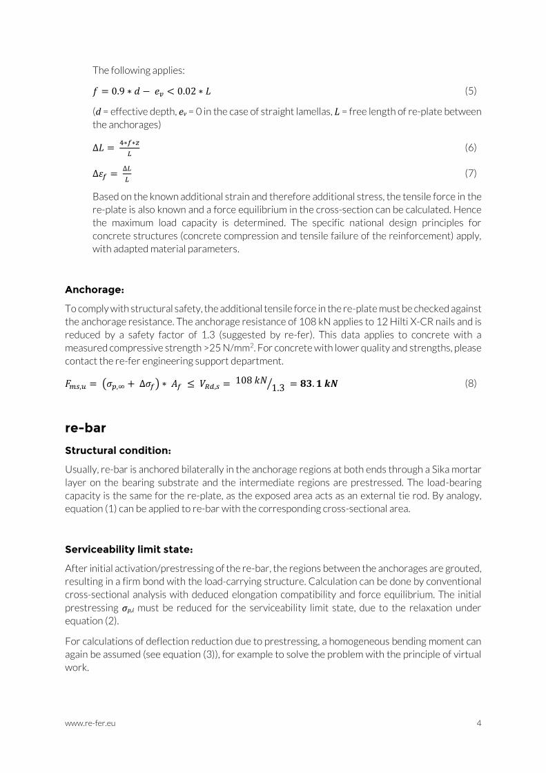
The following applies:
𝑓 = 0.9 ∗ 𝑑 − 𝑒𝑣 < 0.02 ∗ 𝐿 (5)
(d = effective depth, ev = 0 in the case of straight lamellas, L = free length of re-plate between
the anchorages)
∆𝐿 = 4∗𝑓∗𝑧
𝐿 (6)
∆휀𝑓 = ∆𝐿
𝐿 (7)
Based on the known additional strain and therefore additional stress, the tensile force in the
re-plate is also known and a force equilibrium in the cross-section can be calculated. Hence
the maximum load capacity is determined. The specific national design principles for
concrete structures (concrete compression and tensile failure of the reinforcement) apply,
with adapted material parameters.
Anchorage:
To comply with structural safety, the additional tensile force in the re-plate must be checked against
the anchorage resistance. The anchorage resistance of 108 kN applies to 12 Hilti X-CR nails and is
reduced by a safety factor of 1.3 (suggested by re-fer). This data applies to concrete with a
measured compressive strength >25 N/mm2. For concrete with lower quality and strengths, please
contact the re-fer engineering support department.
𝐹𝑚𝑠,𝑢 = (𝜎𝑝,∞ + ∆𝜎𝑓) ∗ 𝐴𝑓 ≤ 𝑉𝑅𝑑,𝑠 = 108 𝑘𝑁1.3⁄ = 𝟖𝟑. 𝟏 𝒌𝑵 (8)
re-bar
Structural condition:
Usually, re-bar is anchored bilaterally in the anchorage regions at both ends through a Sika mortar
layer on the bearing substrate and the intermediate regions are prestressed. The load-bearing
capacity is the same for the re-plate, as the exposed area acts as an external tie rod. By analogy,
equation (1) can be applied to re-bar with the corresponding cross-sectional area.
Serviceability limit state:
After initial activation/prestressing of the re-bar, the regions between the anchorages are grouted,
resulting in a firm bond with the load-carrying structure. Calculation can be done by conventional
cross-sectional analysis with deduced elongation compatibility and force equilibrium. The initial
prestressing σp,i must be reduced for the serviceability limit state, due to the relaxation under
equation (2).
For calculations of deflection reduction due to prestressing, a homogeneous bending moment can
again be assumed (see equation (3)), for example to solve the problem with the principle of virtual
work.
www.re-fer.eu 5
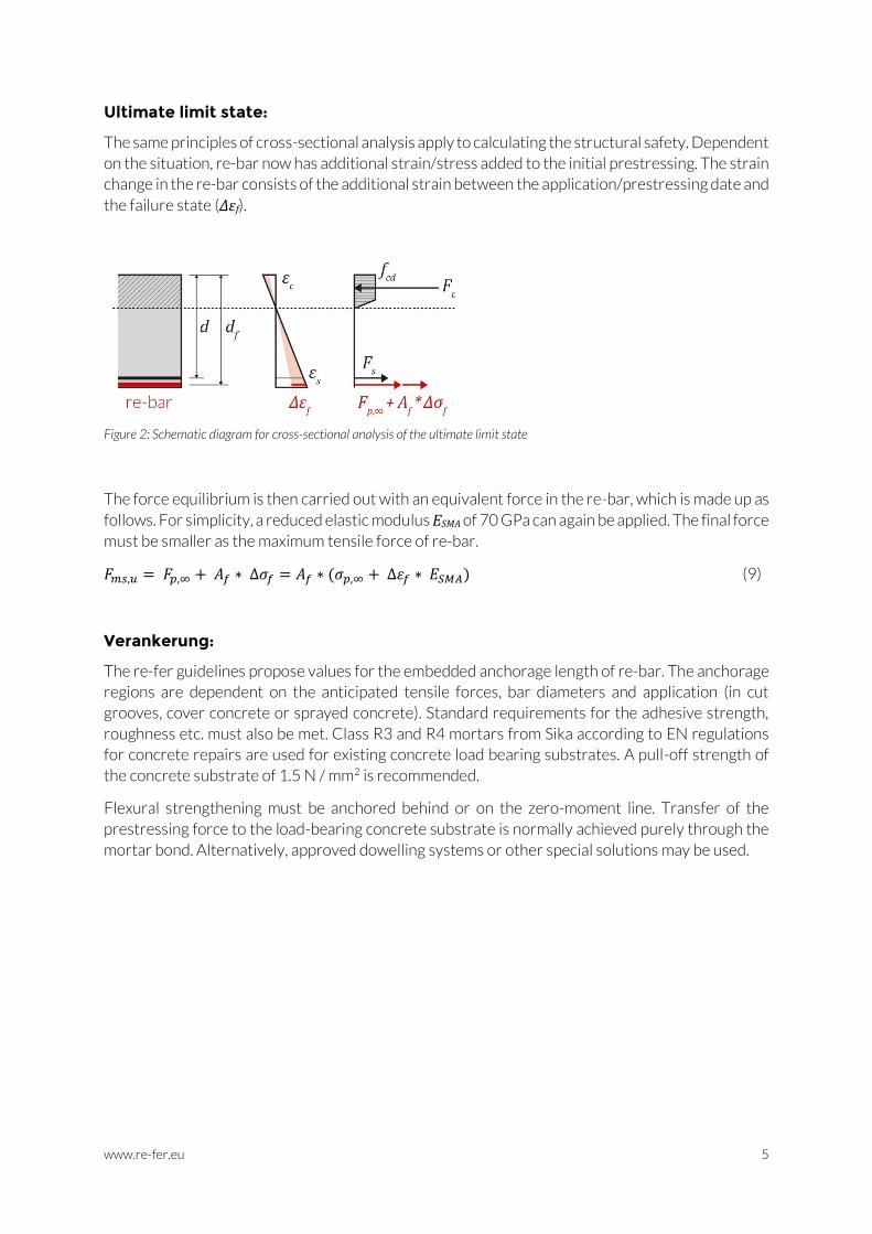
Ultimate limit state:
The same principles of cross-sectional analysis apply to calculating the structural safety. Dependent
on the situation, re-bar now has additional strain/stress added to the initial prestressing. The strain
change in the re-bar consists of the additional strain between the application/prestressing date and
the failure state (Δεf).
Figure 2: Schematic diagram for cross-sectional analysis of the ultimate limit state
The force equilibrium is then carried out with an equivalent force in the re-bar, which is made up as
follows. For simplicity, a reduced elastic modulus ESMA of 70 GPa can again be applied. The final force
must be smaller as the maximum tensile force of re-bar.
𝐹𝑚𝑠,𝑢 = 𝐹𝑝,∞ + 𝐴𝑓 ∗ ∆𝜎𝑓 = 𝐴𝑓 ∗ (𝜎𝑝,∞ + ∆휀𝑓 ∗ 𝐸𝑆𝑀𝐴) (9)
Verankerung:
The re-fer guidelines propose values for the embedded anchorage length of re-bar. The anchorage
regions are dependent on the anticipated tensile forces, bar diameters and application (in cut
grooves, cover concrete or sprayed concrete). Standard requirements for the adhesive strength,
roughness etc. must also be met. Class R3 and R4 mortars from Sika according to EN regulations
for concrete repairs are used for existing concrete load bearing substrates. A pull-off strength of
the concrete substrate of 1.5 N / mm2 is recommended.
Flexural strengthening must be anchored behind or on the zero-moment line. Transfer of the
prestressing force to the load-bearing concrete substrate is normally achieved purely through the
mortar bond. Alternatively, approved dowelling systems or other special solutions may be used.

www.re-fer.eu 6
Notes Specific product parameters should be taken from the current national product data sheets as
required. Values used in design examples may vary from the current material parameters due to
product and standards updates and should always be checked. The re-fer engineering support
assists if anything is unclear and/or for specific design situations. For further information please
visit our website: www.re-fer.eu (e.g. regarding our technologies, references, technical data sheets,
tender texts, test reports etc.). Alternatively, please contact our Technical Support team directly for
specific advice and assistance.
Corrosion
Appropriate measures should be taken in locations with chloride exposure and contamination,
despite the good corrosion resistance of memory®-steel (risk of stress crack corrosion). Mortar
cover on the re-bar should be re-assessed and increased if necessary. For re-plate products, a
special coating is applied at the production facility (SikaCor® EG-1), which then limits the maximum
heat temperature allowed to 165°C and therefore this also limits the maximum prestressing force.
Fire protection
Fire protection is always required for strengthening measures if the standard national fire load
cannot be met without strengthening. The table below is a simple comparative example of the
residual safety margins for fire protection on a load-bearing structure with «low» and alternatively
«high» strengthening levels.
Load examples [kN/m2]
Before strengthening
After strengthening
«low» strengthening level +3.0
«high» strengthening level +5.0
Dead load / applied load 5.0 5.0 5.0
Live load 3.0 3.0 + 3.0 = 6.0 3.0 + 5.0 = 8.0
Service load 8.0 11.0 13.0
Example with global safety factor
8.0 * 1.5 = 12.0 11.0 * 1.5 = 16.5 13.0 * 1.5 = 19.5
Load capacity to be covered 12.0 16.5 19.5
Fire protection Criterion: new working load must be <12.0 (existing load capacity)
- 11.0 < 12.0
Not required 13.0 > 12.00
Required
If a «high» strengthening load level has to be reached, the retrofitting measure must also carry
load in a fire scenario; a fire protection is then necessary for the strengthening product. The same
regulations and standards apply to re-bar laid in concrete or cementitious mortar as for
conventional steel reinforcement. A sprayed, cement-based fire protection mortar is normally
used for re-plate (SikaCem® Pyrocoat).

www.re-fer.eu 7
Design examples
Flexural strengthening with re-plate
At the client’s request, the structural walls (marked red) are to be removed to merge two existing
rooms into one large living room. This change in the static system of the load-bearing structure
would inevitably cause bending moment problems in the deck slab. The example below shows the
flexural strengthening measure of the concrete slab. Other verifications such as the load transfer
to the walls and lower floors, shear forces, punching issues etc., are not considered. The structural
condition is not investigated.
a) b)
Figure 3: a) Model floor plan before, b) after removing the wall
In the existing slab, reinforcement of Ø10@150 (as = 524 mm2 / m') was used and located in all
layers. Concrete slab thickness is hc = 200 mm, concrete quality C30 / 37 and the reinforcement
cover 30 mm. R60 fire resistance is required for the load-bearing elements.
With these design data, bending resistance of mRd = 36 kNm/m' is obtained for the existing 1st/4th
layers (x-direction). In the 2nd/3rd layers the bending resistance is 32 kNm/m'. With the new floor
plan, the existing reinforcement (4th layer) is going to yield under the new permanent load.
Therefore, an articulation joint is modelled in these regions to transfer that moment to the span
(see Figure 3 b)).
Verification at service load level:
Under service loads, the new floor plan shows the following bending moments in x- and y-directions.
At midspan in the main load-bearing direction, the bending resistance of the existing reinforcement
is slightly exceeded. The strengthening system therefore must be fire protected. This is described
in the Fire Protection section that follows.

www.re-fer.eu 8
a) b)
c) d)
Figure 4: Plots of bending moments under permanent service load a) x-direction bottom (1st layer), b) y-direction bottom (2nd layer), c) x-direction top (4th layer), d) y-direction top (3rd layer)
A further factor in serviceability is deflection. Here, the cracked concrete cross-section under
service load in the example has an effective deflection of 16.6 mm. The standards give the
admissible value:
𝑤𝑎𝑙𝑙 ≤ 𝑙300⁄ = 4′600 𝑚𝑚
300⁄ = 15.3 𝑚𝑚

www.re-fer.eu 9
Figure 5: load deflection
Due to the prestressing, a constant moment can be applied at midspan across the approx. 3.0 m
wide slab strip. Here, the established formula from the literature for a constant moment on a simple
beam can be used. For more specialised cases (e.g. continuous beam), the design can be established
by the principle of virtual work.
𝑤 = 𝑀 ∗ 𝑙2
8 ∗ 𝐸𝑐𝐼
A simplified assumption is made that the whole concrete cross-section is cracked. This reduces the
value EcI to EcI/3. The actual equation then becomes:
𝑤 = 𝑤𝑒𝑓𝑓 − 𝑤𝑎𝑙𝑙 = 16.6 𝑚𝑚 − 15.3 𝑚𝑚 = 1.3 𝑚𝑚 ≤ 𝑀𝑝,𝐺𝑍 ∗ 𝑙2
8 ∗ (𝐸𝑐𝐼
3⁄ )
That equation is solved according to n (the number of re-plate plates per metre):
𝑤 = 𝑀𝑝,𝐺𝑍 ∗ 𝑙2
8 ∗ (𝐸𝑐𝐼
3⁄ )=
(𝜎𝑝,𝑖 ∗ 0.85 ∗ 𝐴𝑓 ∗ 𝑧 ∗ 𝒏) ∗ 𝑙2
8 ∗ (𝐸𝑐 ∗ ℎ𝑐
3 ∗ 𝑏12 ∗ 3 )
→ 𝒏 = 𝑤 ∗ 8 ∗ 𝐸𝑐 ∗ ℎ𝑐
3 ∗ 𝑏
12 ∗ 3 ∗ 𝜎𝑝,𝑖 ∗ 0.85 ∗ 𝐴𝑙 ∗ 𝑧 ∗ 𝑙2
= 1.3 𝑚𝑚 ∗ 8 ∗ 33.6 𝐺𝑃𝑎 ∗ (200 𝑚𝑚)3 ∗ 1.0 𝑚
12 ∗ 3 ∗ 380𝑁
𝑚𝑚2 ∗ 0.85 ∗ 120 𝑚𝑚 ∗ 1.5 𝑚𝑚 ∗ 200 𝑚𝑚
2 ∗ (4.6 𝑚)2= 𝟎. 𝟔𝟑
www.re-fer.eu 10
At least 0.63 re-plates per linear metre are required at the midspan. Unless the structural safety
check indicates a larger figure, the strengthening plates therefore are applied every approx. 1.6 m.
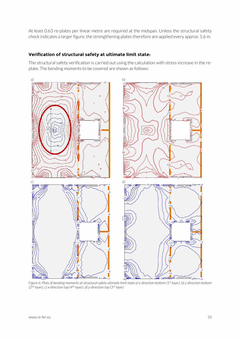
Verification of structural safety at ultimate limit state:
The structural safety verification is carried out using the calculation with stress increase in the re-
plate. The bending moments to be covered are shown as follows:
a) b)
c) d)
Figure 6: Plots of bending moments at structural safety ultimate limit state a) x-direction bottom (1st layer), b) y-direction bottom (2nd layer), c) x-direction top (4th layer), d) y-direction top (3rd layer)

www.re-fer.eu 11
To do this, firstly the elongation growth in the re-plate is calculated. The value for L (free length of
re-plate between the anchorages) is obtained from the bilateral reduction in anchorage length (400
mm) and a safety margin (100 mm):
𝐿 = 4.6 𝑚 − 2 ∗ (400 𝑚𝑚 + 100 𝑚𝑚) = 3.6 𝑚
𝑓 = 0.9 ∗ 𝑑 − 𝑒𝑣 = 0.9 ∗ (0.9 ∗ 200 𝑚𝑚) − 0 = 162 𝑚𝑚 < 0.02 ∗ 𝐿 = 𝟕𝟐 𝒎𝒎
∆휀𝑓 = ∆𝐿
𝐿=
4 ∗ 𝑓 ∗ 𝑧
𝐿2=
4 ∗ 72 𝑚𝑚 ∗ (0.9 ∗ 200 𝑚𝑚)
(4.6 𝑚)2= 𝟎. 𝟒%
The bending moment for strengthening is therefore derived with the final force Fms,u in n re-plates
through an internal lever arm z of about 0.9 * hc:
𝐹𝑚𝑠,𝑢 = (𝜎𝑝,∞ + ∆𝜎) ∗ 𝐴𝑓 = (𝜎𝑝,𝑖 ∗ 0.85 + ∆휀𝑓 ∗ 𝐸𝑆𝑀𝐴) ∗ 𝐴𝑓
= (380𝑁
𝑚𝑚2∗ 0.85 + 0.004 ∗ 70 𝐺𝑃𝑎) ∗ 120 𝑚𝑚 ∗ 1.5 = 108.5 𝑘𝑁 < 𝟖𝟑. 𝟏 𝒌𝑵
𝑀𝑝,𝐺𝑍 = 𝒏 ∗ 𝐹𝑚𝑠,𝑢 ∗ 𝑧 = 𝒏 ∗ 83.1 𝑘𝑁 ∗ 0.9 ∗ 200 𝑚𝑚 ≥ 58.6 𝑘𝑁𝑚 − 36.0 𝑘𝑁𝑚 = 22.6 𝑘𝑁𝑚
→ 𝒏 = 𝑀𝑝,𝐺𝑍
𝐹𝑚𝑠,𝑢 ∗ 𝑧=
22.6 𝑘𝑁𝑚
83.1 𝑘𝑁 ∗ 0.9 ∗ 200 𝑚𝑚= 𝟏. 𝟓
Hence, to cover the structural safety requirements in the overstressed regions (around 4.5 m), 1.5
re-plates are necessary per linear metre – e.g. one plate every 0.66 m (a total of 7).
Figure 7: Position of re-plate strengthening
7 x re-plate
l = 4.40 m, every 0.66 m,
with fire protection
www.re-fer.eu 12
Fire protection:
For fire, the quasi-permanent loads must be covered. As the flexural load capacity in the existing
structure is insufficient, the strengthening measures are protected for R60. The sprayed, cement-
based fire protection mortar SikaCem® Pyrocoat is used with a layer-thickness according to the
current table in the re-plate data sheet.
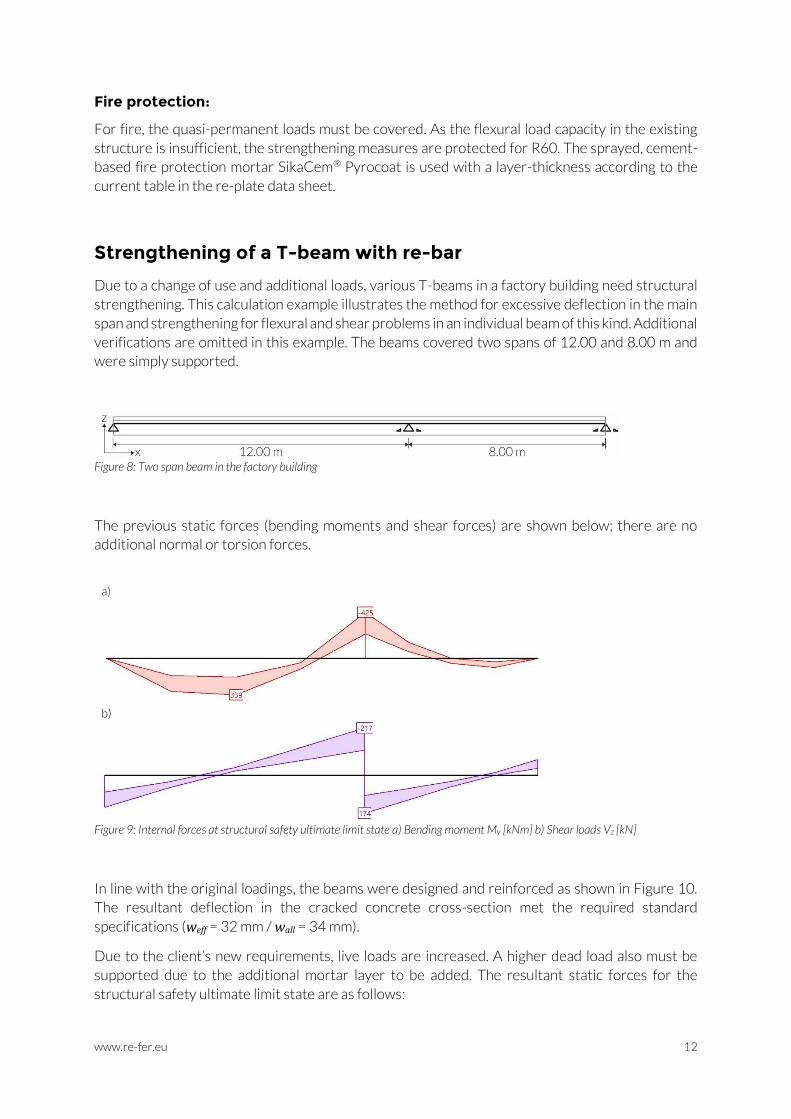
Strengthening of a T-beam with re-bar
Due to a change of use and additional loads, various T-beams in a factory building need structural
strengthening. This calculation example illustrates the method for excessive deflection in the main
span and strengthening for flexural and shear problems in an individual beam of this kind. Additional
verifications are omitted in this example. The beams covered two spans of 12.00 and 8.00 m and
were simply supported.
Figure 8: Two span beam in the factory building
The previous static forces (bending moments and shear forces) are shown below; there are no
additional normal or torsion forces.
a)
b)
Figure 9: Internal forces at structural safety ultimate limit state a) Bending moment My [kNm] b) Shear loads Vz [kN]
In line with the original loadings, the beams were designed and reinforced as shown in Figure 10.
The resultant deflection in the cracked concrete cross-section met the required standard
specifications (weff = 32 mm / wall = 34 mm).
Due to the client’s new requirements, live loads are increased. A higher dead load also must be
supported due to the additional mortar layer to be added. The resultant static forces for the
structural safety ultimate limit state are as follows:

www.re-fer.eu 13
Previous internal forces Previous resistances New internal forces
Bending moment [kNm]
MEd +339 -425
MRd +355 -440
MEd +449 -550
Shear force [kN] VEd 217 VRd 230 VEd 285
Figure 10: Existing cross-section of T-beams
Verification of structural safety at ultimate limit state:
Firstly, the structural safety ultimate limit state is investigated. The new internal forces are also
shown in detail below.
a)
b)
Figure 11: New internal forces at structural safety limit state a) Bending moment My [kNm] b) Shear forces Vz [kN]
Due to the additional loads, a shear problem occurs in a region about 1.5 m wide adjacent to the
central point of support. The missing transverse shear strength of ca. 55 kN/m' is accommodated
using re-bar 10 U-profiles. For simplicity, only the prestressing force (no strain increase up to shear
failure) on the double shear stirrups is assumed.

www.re-fer.eu 14
𝑉𝑅𝑑,𝑠 = 2∗𝜎𝑝,∞∗ 𝐴𝑓
𝑠∗ 𝑧 ∗ cot(45°) =
2∗350𝑁
𝑚𝑚2∗ 0.85 ∗ 89.9 𝑚𝑚2
0.5 𝑚∗ ~0.7𝑚 ∗ cot (45°) = 75 𝑘𝑁/𝑚′
Accordingly, a total of three re-bar 10 U-profiles at a 0.5 m interval are necessary to strengthen the
region. The stirrups are guided around the existing, roughened concrete surface and over the
additional longitudinal re-bar. They are then embedded in sprayed mortar / grouted in the flange
(anchorage over the neutral axis). The re-bar shear stirrups are electrically heated/activated from
above.
Spacers are installed to ensure that there is no contact with the existing reinforcement (electric
tension loss during heating process).
In the larger sub-span, the new bending effect exceeds the previous resistance by some 94 kNm.
Over the whole span, three re-bar 16 are installed on the bottom side of the web and embedded in
sprayed mortar. Across the central support, the negative bending moment exceeds the permitted
load over a length of ca. 1.3 by approx. 110 kNm. In that zone, four re-bars 10 are laid in fresh
concrete cover (Note: anchorage of strengthening behind the zero-moment line). The
strengthening bars are grouted in the anchorage region and heated after hardening, e.g. with a gas
burner. Finally, the remaining zones are also embedded.
Flexural verification of the new cross-section can be done with standard design software. The new
resistance levels are listed in the table below.
Figure 12: new cross-section of T-beams with re-bar flexural strengthening
Previous internal forces
Previous resistance
New internal forces
New resistance
Bending moment [kNm]
MEd +339 -425
MRd +355 -440
MEd +449 -550
MRd +569 -553
Shear force [kN] VEd 217 VRd 230 VEd 285 VRd 315

www.re-fer.eu 15
The following input parameters are used, amongst others, for the modelling:
Tendon attributes:
- Prestraining ε0 = 0.57% for re-bar 10 and 0.46% for re-bar 16 (which gives theoretical prestressing respectively of: Elastic modulus * ε0 = 400 N/mm2, and 320 N/mm2)
- Prestressing with bond - Loss factor P∞/P0 = 0.85 (relaxation)
Material properties:
- Elastic modulus = 70 kN/mm2 (re-bar elastic modulus after activation) - fp0.1k = 520 N/mm2 (Design value reduced by safety factor) - εud = 30%
Verification at service load level:
By installing prestressed strengthening elements embedded in mortar, crack openings are limited
at the surface, and load is removed from the existing reinforcement. In addition to the improved
durability, this example also investigates the deflection. Due to the new loads, the vertical deflection
in the large span is calculated at about 39 mm. Flexural strengthening with three re-bar 16 implies
a constant bending moment which counteracts the deflection. The resulting 5 mm (weff = 39 mm /
wall = 34 mm) should be eliminated with this measure.
The deformation of the statically indeterminate system implied by the prestressing can be
calculated in various ways. Here, the principle of virtual work for the statically indeterminate
system is used. As a basic system (BS), an articulated joint is introduced at the central support. For
simplicity, the prestressing in the negative bending region is not included, though it would also have
a positive effect.
DS:
LS:
BS and RF:
BS and RF:
𝑀0(𝑀𝑝,𝐺𝑍)
on BS:
𝑀0(𝐹 = 1)
on BS:
𝑀1(𝑋1 = 1) on BS:
𝑀1(𝑋1 = 1)
on BS:
Figure 13: Simplification and reduction of the statically indeterminate system and principle of virtual work
𝛿10 = ∫ 𝑀1 ∗𝑀0
𝐸𝑐𝐼𝑑𝑥 =
1
2∗ (+1) ∗ (−𝑀𝑝,𝐺𝑍) ∗
𝑙
𝐸𝑐𝐼+ 0 = −
𝑀𝑝,𝐺𝑍 ∗ 𝑙
2 ∗ 𝐸𝑐𝐼
𝛿11 = ∫ 𝑀1 ∗𝑀1
𝐸𝑐𝐼𝑑𝑥 =
1
3∗ (+1)2 ∗
(1 +23) 𝑙
𝐸𝑐𝐼=
5 ∗ 𝑙
9 ∗ 𝐸𝑐𝐼
𝛿10 + 𝑋1 ∗ 𝛿11 = 0 → 𝑋1 = −𝛿10
𝛿11=
𝟗
𝟏𝟎𝑴𝒑,𝑮𝒁

www.re-fer.eu 16
The deformation w can be deduced from this as follows:
𝑤 = ∫ 𝑀0 ∗𝑀0
𝐸𝑐𝐼𝑑𝑥 + 𝑋1 ∗ ∫ 𝑀0 ∗
𝑀1
𝐸𝑐𝐼𝑑𝑥
=1
2∗ (−
𝑙
4) ∗ (−𝑀𝑝,𝐺𝑍) ∗
𝑙
𝐸𝑐𝐼+ (
9
10𝑀𝑝,𝐺𝑍) ∗
1
4∗ (−
𝑙
4) ∗ (+1) ∗
𝑙
𝐸𝑐𝐼
= 𝑀𝑝,𝐺𝑍 ∗ 𝑙2
𝐸𝑐𝐼∗ (
1
8−
9
160) =
𝟏𝟏 ∗ 𝑴𝒑,𝑮𝒁 ∗ 𝒍𝟐
𝟏𝟔𝟎 ∗ 𝑬𝒄𝑰
Equation (3) gives the constant bending moment Mp,GZ across the 12.00 m:
𝑀𝑝,𝐺𝑍 = 𝐹𝑝,∞ ∗ 𝑧 = 𝜎𝑝,∞ ∗ 𝐴𝑓 ∗ 𝑧 = 3 ∗ 320 𝑁
𝑚𝑚2∗ 0.85 ∗ 211.2 𝑚𝑚2 ∗ ~0.66 𝑚 = 114 𝑘𝑁𝑚
In addition, a reduced, cracked bending stiffness of the concrete cross-section is estimated (EcIcracked
= EcI/3) and included in the equation.
𝑤 =𝟏𝟏 ∗ 𝑴𝒑,𝑮𝒁 ∗ 𝒍𝟐
𝟏𝟔𝟎 ∗ (𝑬𝒄𝑰
𝟑⁄ )=
11 ∗ 114 𝑘𝑁𝑚 ∗ (12.00 𝑚)2
160 ∗ 647′000 𝑘𝑁𝑚2
3
= 5.2 𝑚𝑚
The three re-bars installed to increase the structural safety consequently contribute to a reduction
in the deflection of around 5 mm. The verification is achieved.
Verification of anchorage regions:
The negative and positive bending resistance was determined by cross-sectional analysis. For the
negative flexural strengthening, four re-bar 10 are used. In this example the maximum tensile forces
of the re-bars shall be bonded over the new mortar cover (1.10 m width). A bonding strength of 1.5
N/mm2 (tensile adhesion) is assumed to design the anchorage length lb. The resistance is finally
reduced by a safety factor of 1.5:
𝐹𝑝,𝑖(𝑛𝑒𝑔𝑎𝑡𝑖𝑣𝑒) = 4 ∗ 𝜎𝑝,𝑖 ∗ 𝐴𝑓 = 4 ∗ 520𝑁
𝑚𝑚2 ∗ 89.9 𝑚𝑚2 = 187.0 𝑘𝑁
𝐹𝑝,𝑖 ≤𝑙𝑏 ∗ 1.10 𝑚 ∗ 1.5
𝑁
𝑚𝑚2
1.5 → 𝑙𝑏 = 𝟏𝟕𝟎 𝒎𝒎
The region of the anchorage is designed with a full layer of cover mortar over a length of approx.
300 mm and the width of 1.10 m.
For the positive flexural strengthening requirements, three re-bar 16 are applied to the underside
of the beam (width b = 300 mm). In this example also, the maximum tensile force shall be anchored.
𝐹𝑝,𝑖(𝑝𝑜𝑠𝑖𝑡𝑖𝑣𝑒) = 3 ∗ 𝜎𝑝,𝑖 ∗ 𝐴𝑓 = 3 ∗ 520𝑁
𝑚𝑚2 ∗ 211.2 𝑚𝑚2 = 329.5 𝑘𝑁
𝐹𝑝,𝑖 ≤𝑙𝑏 ∗300 𝑚𝑚 ∗ 1.5
𝑁
𝑚𝑚2
1.5 → 𝑙𝑏 = 𝟏′𝟎𝟗𝟖 𝒎𝒎

www.re-fer.eu 17
This value can be reduced with different flexible anchorage solutions. As example, the positive
effect of additional compression of the cover layer by three re-bar 10 U-profiles is shown because
a prestressed shear strengthening is applied anyways. The tensile adhesion between concrete and
mortar (1.5 N/mm2) increases with the prestressed double-shear stirrups (Relaxation of prestress
0.85 / safety factor 1.5).
𝐹𝑝,𝑖 = 329.5 𝑘𝑁 ≤𝑙𝑏∗𝑏∗(1.5
𝑁
𝑚𝑚2 + 3∗2∗ 𝜎𝑝,∞∗ 𝐴𝑓
𝑙𝑏∗𝑏⁄ )
1.5=
𝑙𝑏∗300 𝑚𝑚∗(1.5 𝑁
𝑚𝑚2+ 3∗2∗0.85∗350 𝑁 𝑚𝑚2⁄ ∗89.9 𝑚𝑚2
𝑙𝑏∗300 𝑚𝑚⁄ )
1.5 → 𝑙𝑏 = 𝟕𝟒𝟐 𝒎𝒎
Three re-bar 10 U-profiles are applied for the anchorage on the left side (support A), analogue to
the centre support B. The anchorage length is 750 mm.
Schematic sketch of the beam strengthening measures:
Figure 14: Sketch of strengthening works with re-bar longitudinal reinforcement and re-bar shear stirrups
For conventional flexural strengthening measures with re-bar slack applied stirrups (steel
B500B) can be used, too. Since it is a more cost-effective alternative preventing the
anchorage layer from detaching
References
[1] Hegger, J. and K. Kordina, Report 30-0107/001: Determination of flexural load carrying capacity of
construction elements with prestressing without bond (in German). 1985, Braunschweig Technical University:
Braunschweig, Germany.
[2] Bruggeling, A.S.G., Voorspanning zonder aanhechting, enkelstrengsystemen. 1976, Delft Technical University:
Delft, Netherlands.