Embed Size (px)
Citation preview
Crestron DigitalMedia™ Infrastructure Guide
2
IntroductionThis guide is intended to explain the different infrastructure options and require-ments for DigitalMedia™ installations. DM® is an extremely versatile AV distribu-tion system, capable of switching and transporting virtually any video signal type over a mixed copper/fiber infrastructure. In addition to digital and analog HD audio and video, DM also distributes Ethernet, USB-HID and control signals.
Whether you’re a seasoned DMC-D or this is your introduction to DM, this guide will help you determine what infrastructure is right for your project.
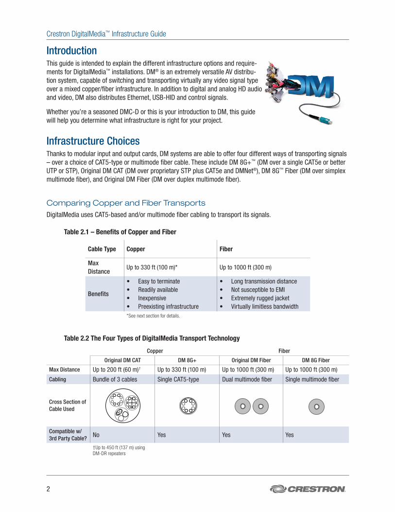
Infrastructure ChoicesThanks to modular input and output cards, DM systems are able to offer four different ways of transporting signals – over a choice of CAT5-type or multimode fiber cable. These include DM 8G+™ (DM over a single CAT5e or better UTP or STP), Original DM CAT (DM over proprietary STP plus CAT5e and DMNet®), DM 8G™ Fiber (DM over simplex multimode fiber), and Original DM Fiber (DM over duplex multimode fiber).
Comparing Copper and Fiber Transports
DigitalMedia uses CAT5-based and/or multimode fiber cabling to transport its signals.
Table 2.1 – Benefits of Copper and Fiber
Cable Type Copper Fiber
Max Distance
Up to 330 ft (100 m)* Up to 1000 ft (300 m)
Benefits
• Easy to terminate• Readily available• Inexpensive• Preexisting infrastructure
• Long transmission distance• Not susceptible to EMI• Extremely rugged jacket• Virtually limitless bandwidth
*See next section for details.
Table 2.2 The Four Types of DigitalMedia Transport Technology
Copper Fiber
Original DM CAT DM 8G+ Original DM Fiber DM 8G Fiber
Max Distance Up to 200 ft (60 m)† Up to 330 ft (100 m) Up to 1000 ft (300 m) Up to 1000 ft (300 m)
Cabling Bundle of 3 cables Single CAT5-type Dual multimode fiber Single multimode fiber
Cross Section of Cable Used
0.185 in0.526 in 0.36 in 0.185 in
DM 8G STPDM-CBL-8G
DM “D” CableDM-CBL-D
CresFiber 8GCRESFIBER-8G
DM CATDM-CBL
0.185 in0.526 in 0.36 in 0.185 in
DM 8G STPDM-CBL-8G
DM “D” CableDM-CBL-D
CresFiber 8GCRESFIBER-8G
DM CATDM-CBL
0.185 in0.526 in 0.36 in 0.185 in
DM 8G STPDM-CBL-8G
DM “D” CableDM-CBL-D
CresFiber 8GCRESFIBER-8G
DM CATDM-CBL
0.185 in0.526 in 0.36 in 0.185 in
DM 8G STPDM-CBL-8G
DM “D” CableDM-CBL-D
CresFiber 8GCRESFIBER-8G
DM CATDM-CBL
Compatible w/ 3rd Party Cable? No Yes Yes Yes
†Up to 450 ft (137 m) using DM-DR repeaters
Crestron DigitalMedia™ Infrastructure Guide
800-237-2041 | crestron.com/digitalmedia 3
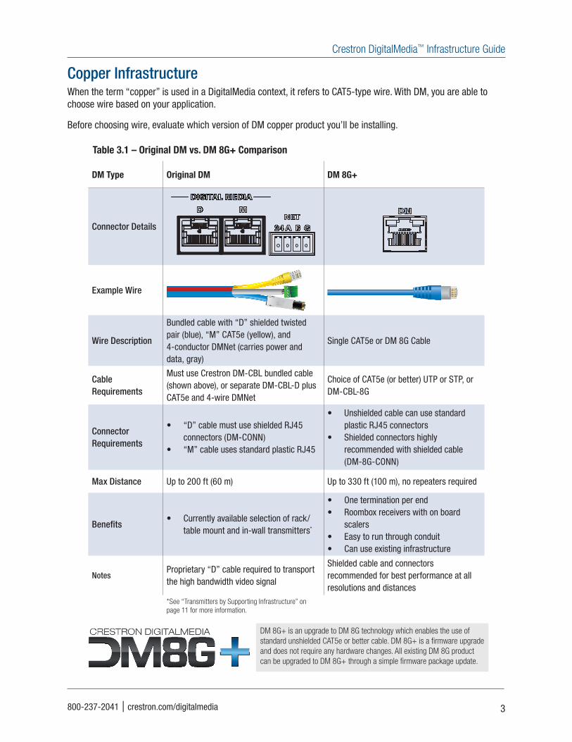
Copper InfrastructureWhen the term “copper” is used in a DigitalMedia context, it refers to CAT5-type wire. With DM, you are able to choose wire based on your application.
Before choosing wire, evaluate which version of DM copper product you’ll be installing.
Table 3.1 – Original DM vs. DM 8G+ Comparison
DM Type Original DM DM 8G+
Connector Details
Example Wire
Wire Description
Bundled cable with “D” shielded twisted pair (blue), “M” CAT5e (yellow), and 4-conductor DMNet (carries power and data, gray)
Single CAT5e or DM 8G Cable
Cable Requirements
Must use Crestron DM-CBL bundled cable (shown above), or separate DM-CBL-D plus CAT5e and 4-wire DMNet
Choice of CAT5e (or better) UTP or STP, or DM-CBL-8G
Connector Requirements
• “D” cable must use shielded RJ45 connectors (DM-CONN)
• “M” cable uses standard plastic RJ45
• Unshielded cable can use standard plastic RJ45 connectors
• Shielded connectors highly recommended with shielded cable (DM-8G-CONN)
Max Distance Up to 200 ft (60 m) Up to 330 ft (100 m), no repeaters required
Benefits• Currently available selection of rack/
table mount and in-wall transmitters*
• One termination per end• Roombox receivers with on board
scalers• Easy to run through conduit• Can use existing infrastructure
NotesProprietary “D” cable required to transport the high bandwidth video signal
Shielded cable and connectors recommended for best performance at all resolutions and distances
*See “Transmitters by Supporting Infrastructure” on page 11 for more information.
DM 8G+ is an upgrade to DM 8G technology which enables the use of standard unshielded CAT5e or better cable. DM 8G+ is a firmware upgrade and does not require any hardware changes. All existing DM 8G product can be upgraded to DM 8G+ through a simple firmware package update.
Crestron DigitalMedia™ Infrastructure Guide
4
Copper Wiring and Distance Details
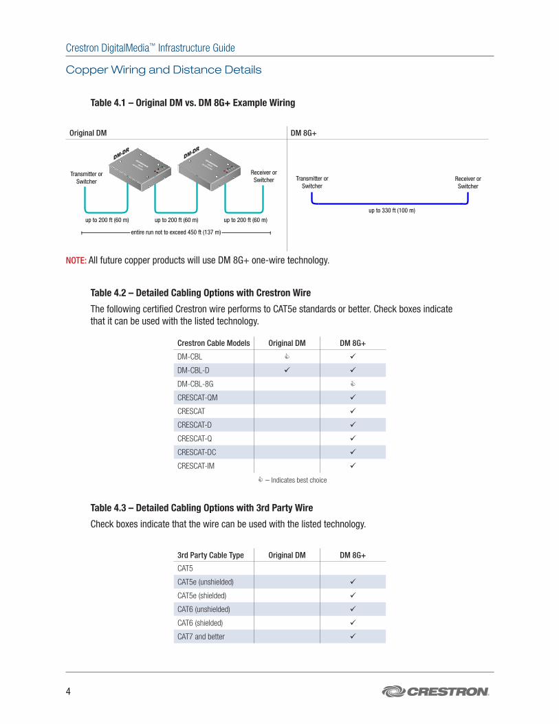
Table 4.1 – Original DM vs. DM 8G+ Example Wiring
Original DM DM 8G+
DM-DRDM-DR
PWRLINKERRSETUP
DM-DRDM REPEATER
PWRLINKERRSETUP
DM-DRDM REPEATER
up to 200 ft (60 m)
DM-RMC-100-C
DM-TX-201-C
COM
HDMI OUT
GND
TXRXRTS
CTS
SGSS
1
2
IR
LAN
DM IN
RESET
SETUP
24 V
0.75A MAX
DM-RMC-100-C
DM ROOM CONTROLLER
USB HID
HDMI
RGB
AUDIOSETUP
D M - T X - 2 0 1 - C
D M C O M P U T E R C E N T E R
RESET
IN
LAN
DM OUT
HDMI OUT
PWR
24 VDC
0.75A
330 ft.
Transmitter or Switcher
Receiver or Switcher
entire run not to exceed 450 ft (137 m)
up to 200 ft (60 m) up to 200 ft (60 m)
Transmitter or Switcher
Receiver or Switcher
up to 330 ft (100 m)
NOTE: All future copper products will use DM 8G+ one-wire technology.
Table 4.2 – Detailed Cabling Options with Crestron Wire
The following certified Crestron wire performs to CAT5e standards or better. Check boxes indicate that it can be used with the listed technology.
Crestron Cable Models Original DM DM 8G+
DM-CBL
DM-CBL-D
DM-CBL-8G
CRESCAT-QM
CRESCAT
CRESCAT-D
CRESCAT-Q
CRESCAT-DC
CRESCAT-IM
– Indicates best choice
Table 4.3 – Detailed Cabling Options with 3rd Party Wire
Check boxes indicate that the wire can be used with the listed technology.
3rd Party Cable Type Original DM DM 8G+
CAT5
CAT5e (unshielded)
CAT5e (shielded)
CAT6 (unshielded)
CAT6 (shielded)
CAT7 and better
Crestron DigitalMedia™ Infrastructure Guide
800-237-2041 | crestron.com/digitalmedia 5
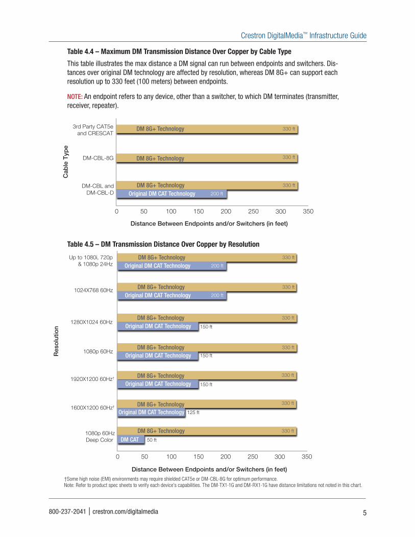
Table 4.4 – Maximum DM Transmission Distance Over Copper by Cable Type
This table illustrates the max distance a DM signal can run between endpoints and switchers. Dis-tances over original DM technology are affected by resolution, whereas DM 8G+ can support each resolution up to 330 feet (100 meters) between endpoints.
NOTE: An endpoint refers to any device, other than a switcher, to which DM terminates (transmitter, receiver, repeater).
50 100 150 200 250 300 3500
Distance Between Endpoints and/or Switchers (in feet)
3rd Party CAT5e and CRESCAT
DM-CBL-8G
DM-CBL and DM-CBL-D
330 ft
330 ft
330 ft
200 ft
DM 8G+ Technology
DM 8G+ Technology
DM 8G+ TechnologyOriginal DM CAT Technology
50 100 150 200 250 300 3500
1920X1200 60Hz†
1600X1200 60Hz†
1080p 60Hz Deep Color†
330 ft
330 ft
330 ftDM 8G+ Technology
DM 8G+ Technology
DM 8G+ Technology
330 ftDM 8G+ Technology
330 ft
150 ft
DM 8G+ TechnologyOriginal DM CAT Technology
330 ft
200 ft
DM 8G+ TechnologyOriginal DM CAT Technology
330 ft
200 ft
DM 8G+ TechnologyOriginal DM CAT Technology
Up to 1080i, 720p & 1080p 24Hz
1024X768 60Hz
1280X1024 60Hz
1080p 60Hz150 ftOriginal DM CAT Technology
150 ftOriginal DM CAT Technology
125 ft
50 ft
Original DM CAT Technology
DM CAT
Distance Between Endpoints and/or Switchers (in feet)
250 500 750 10000
CresFiber 8G
CresFiber
OM3 (or better)
500 ft
1000 ft
1000 ft
DM 8G Fiber Technology
DM 8G Fiber Technology
DM 8G Fiber TechnologyOriginal DM Fiber Technology
1000 ftOriginal DM Fiber Technology
500 ft
1000 ftOriginal DM Fiber Technology
Distance Between Endpoints and/or Switchers (in feet)
Table 4.5 – DM Transmission Distance Over Copper by Resolution
50 100 150 200 250 300 3500
Distance Between Endpoints and/or Switchers (in feet)
3rd Party CAT5e and CRESCAT
DM-CBL-8G
DM-CBL and DM-CBL-D
330 ft
330 ft
330 ft
200 ft
DM 8G+ Technology
DM 8G+ Technology
DM 8G+ TechnologyOriginal DM CAT Technology
50 100 150 200 250 300 3500
1920X1200 60Hz†
1600X1200 60Hz†
1080p 60Hz Deep Color
330 ft
330 ft
330 ftDM 8G+ Technology
DM 8G+ Technology
DM 8G+ Technology
330 ftDM 8G+ Technology
330 ft
150 ft
DM 8G+ TechnologyOriginal DM CAT Technology
330 ft
200 ft
DM 8G+ TechnologyOriginal DM CAT Technology
330 ft
200 ft
DM 8G+ TechnologyOriginal DM CAT Technology
Up to 1080i, 720p & 1080p 24Hz
1024X768 60Hz
1280X1024 60Hz
1080p 60Hz150 ftOriginal DM CAT Technology
150 ftOriginal DM CAT Technology
125 ft
50 ft
Original DM CAT Technology
DM CAT
Distance Between Endpoints and/or Switchers (in feet)
250 500 750 10000
CresFiber 8G
CresFiber
OM3 (or better)
500 ft
1000 ft
1000 ft
DM 8G Fiber Technology
DM 8G Fiber Technology
DM 8G Fiber TechnologyOriginal DM Fiber Technology
1000 ftOriginal DM Fiber Technology
500 ft
1000 ftOriginal DM Fiber Technology
Distance Between Endpoints and/or Switchers (in feet)
†Some high noise (EMI) environments may require shielded CAT5e or DM-CBL-8G for optimum performance.Note: Refer to product spec sheets to verify each device’s capabilities. The DM-TX1-1G and DM-RX1-1G have distance limitations not noted in this chart.
Crestron DigitalMedia™ Infrastructure Guide
6
DM 8G+ Performance over Copper
DM 8G+ Technology Minimizes Errors without Compression
DM 8G+ transmits high resolution digital signals over unshielded CAT5e (UTP) with minimal errors. DM 8G+ tech-nology maintains signal integrity over UTP without using compression, making it easy to upgrade existing QM, PVID and other analog distribution systems while delivering the highest quality HD video and audio, along with Ethernet, USB-HID and control.
DM 8G+ Best Practices
• Unshielded CAT5e is approved for use with DM 8G+.
• Shielded cable is advantageous only if it is terminated with shielded connectors.
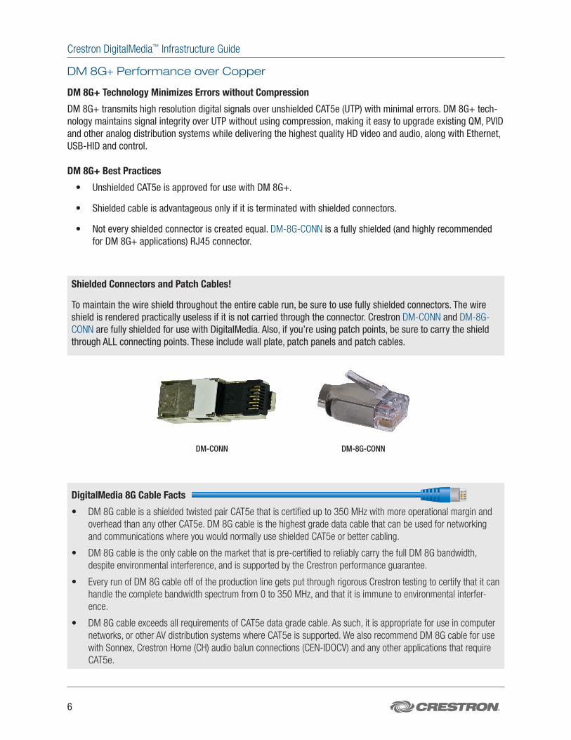
• Not every shielded connector is created equal. DM-8G-CONN is a fully shielded (and highly recommended for DM 8G+ applications) RJ45 connector.
Shielded Connectors and Patch Cables!
To maintain the wire shield throughout the entire cable run, be sure to use fully shielded connectors. The wire shield is rendered practically useless if it is not carried through the connector. Crestron DM-CONN and DM-8G-CONN are fully shielded for use with DigitalMedia. Also, if you’re using patch points, be sure to carry the shield through ALL connecting points. These include wall plate, patch panels and patch cables.
DM-CONN DM-8G-CONN
DigitalMedia 8G Cable Facts
• DM 8G cable is a shielded twisted pair CAT5e that is certified up to 350 MHz with more operational margin and overhead than any other CAT5e. DM 8G cable is the highest grade data cable that can be used for networking and communications where you would normally use shielded CAT5e or better cabling.
• DM 8G cable is the only cable on the market that is pre-certified to reliably carry the full DM 8G bandwidth, despite environmental interference, and is supported by the Crestron performance guarantee.
• Every run of DM 8G cable off of the production line gets put through rigorous Crestron testing to certify that it can handle the complete bandwidth spectrum from 0 to 350 MHz, and that it is immune to environmental interfer-ence.
• DM 8G cable exceeds all requirements of CAT5e data grade cable. As such, it is appropriate for use in computer networks, or other AV distribution systems where CAT5e is supported. We also recommend DM 8G cable for use with Sonnex, Crestron Home (CH) audio balun connections (CEN-IDOCV) and any other applications that require CAT5e.
Crestron DigitalMedia™ Infrastructure Guide
800-237-2041 | crestron.com/digitalmedia 7
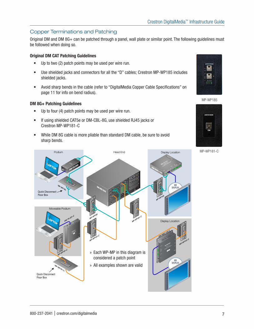
Copper Terminations and Patching
Original DM and DM 8G+ can be patched through a panel, wall plate or similar point. The following guidelines must be followed when doing so.
Original DM CAT Patching Guidelines
• Up to two (2) patch points may be used per wire run.
• Use shielded jacks and connectors for all the “D” cables; Crestron MP-WP185 includes shielded jacks.
• Avoid sharp bends in the cable (refer to “DigitalMedia Copper Cable Specifications” on page 11 for info on bend radius).
DM 8G+ Patching Guidelines
• Up to four (4) patch points may be used per wire run.
• If using shielded CAT5e or DM-CBL-8G, use shielded RJ45 jacks or Crestron MP-WP181-C
• While DM 8G cable is more pliable than standard DM cable, be sure to avoid sharp bends.
LAN
D
M
D
M
D
M
D
M
DM OUTPUTS
DM OUTPUTS
D
M
D
M
D
M
D
M
5
6
7
8
5
6
7
8
1
2
3
4
100-250V~4.0A
50/60 Hz
1
2
3
4
24 A B GE I G
24 A B GE I G
24 A B GE I G
24 A B GE I G
24 A B GE I G
24 A B GE I G
24 A B GE I G
24 A B GE I G
HDMI
HDMI
HDMI OUT
DIGITAL MEDIA
D
M
AUDIO OUT
DMC-CAT-DSP
HDMI OUT
DIGITAL MEDIA
D
M
AUDIO OUT
DMC-CAT-DSP
AUDIO OUTR
L
HDMI OUT
HDMI IN
USB HIDDMC-HDHDMI OUT
AUDIO OUTR
L
DMC-C
DM IN P
OE IN
DM-MD-8X8
MP-WP185
HDMI
RGB
USB HID
AUDIO
IN
PWR DM LINK HDMIIN
RGB INSETUP RESET
DM-TX-200
DM TRANSMIT
TER
CRESTRON
DM OUT
D
M
G B A 24
DM-TX-200
DMNET24 A B G
DM
DM
NET
24 A B GM
D
MP-WP185
DM
NET
24 A B GM
D
MP-WP185
LAPTOPHDMI
COM
GND TX RX RTS CTS
SENS
S G
IR
1 2S G S G
USB
RELAY 1 2
PWRDM
LINKVIDEO
CNTRL
SETUP
CRESTRON
DM-RMC100
DM ROOM CONTROLLER
DM-RMC-100
HDDISPLAY
Podium
Moveable Podium
Head End Display Location
DM
DM-TX-201-C
D M
MP-WP181-C
MP-WP181-C
MP-WP181-C
USB HID
HDMI
RGB
AUDIOSETUP
D M - T X - 2 0 1 - C
D M C O M P U T E R C E N T E R
RESET
IN
LAN
DM OUT
HDMI OUT
PWR
24 VDC
0.75A
LAPTOP
D M
MP-WP181-C
MP-WP181-C
D M
COM
HDMI OUT
GND
TXRXRTS
CTS
SGSS
1
2
IR
LAN
DM IN
RESET
SETUP
24 V
0.75A MAX
DM-RMC-100-C
DM ROOM CONTROLLER
HDDISPLAY
Display Location
DM-RMC-100-C
Quick Disconnect Floor Box
Quick Disconnect Floor Box
HDMI OUT
AUDIO OUTR
LDMC-C
DM IN P
OE IN
HDMI
DM OUTPOE IN
+ - G + -
POE IN
DMCO-53
DM OUT
HDMI
HDMI
+ - G + -
D M
MP-WP185
MP-WP181-C
» Each WP-MP in this diagram is considered a patch point
» All examples shown are valid
Crestron DigitalMedia™ Infrastructure Guide
8
Fiber Infrastructure
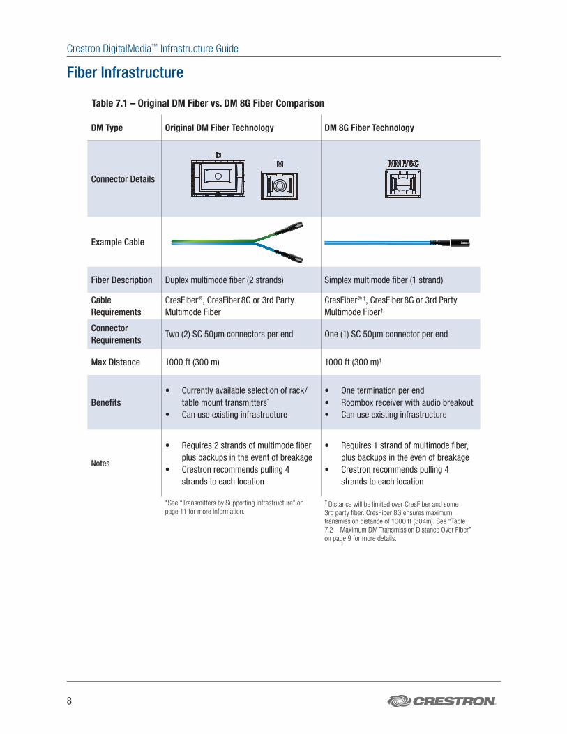
Table 7.1 – Original DM Fiber vs. DM 8G Fiber Comparison
DM Type Original DM Fiber Technology DM 8G Fiber Technology
Connector Details
Example Cable
Fiber Description Duplex multimode fiber (2 strands) Simplex multimode fiber (1 strand)
Cable Requirements
CresFiber®, CresFiber 8G or 3rd Party Multimode Fiber
CresFiber® †, CresFiber 8G or 3rd Party Multimode Fiber†
Connector Requirements
Two (2) SC 50µm connectors per end One (1) SC 50µm connector per end
Max Distance 1000 ft (300 m) 1000 ft (300 m)†
Benefits• Currently available selection of rack/
table mount transmitters*
• Can use existing infrastructure
• One termination per end• Roombox receiver with audio breakout• Can use existing infrastructure
Notes
• Requires 2 strands of multimode fiber, plus backups in the event of breakage
• Crestron recommends pulling 4 strands to each location
• Requires 1 strand of multimode fiber, plus backups in the even of breakage
• Crestron recommends pulling 4 strands to each location
*See “Transmitters by Supporting Infrastructure” on page 11 for more information.
† Distance will be limited over CresFiber and some 3rd party fiber. CresFiber 8G ensures maximum transmission distance of 1000 ft (304m). See “Table 7.2 – Maximum DM Transmission Distance Over Fiber” on page 9 for more details.
Crestron DigitalMedia™ Infrastructure Guide
800-237-2041 | crestron.com/digitalmedia 9
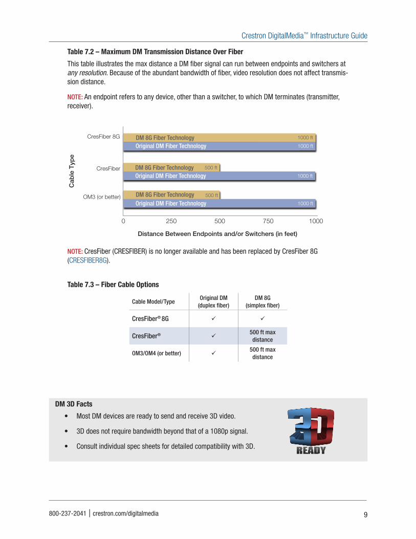
Table 7.2 – Maximum DM Transmission Distance Over Fiber
This table illustrates the max distance a DM fiber signal can run between endpoints and switchers at any resolution. Because of the abundant bandwidth of fiber, video resolution does not affect transmis-sion distance.
NOTE: An endpoint refers to any device, other than a switcher, to which DM terminates (transmitter, receiver).
50 100 150 200 250 300 3500
Distance Between Endpoints and/or Switchers (in feet)
3rd Party CAT5e and CRESCAT
DM-CBL-8G
DM-CBL and DM-CBL-D
330 ft
330 ft
330 ft
200 ft
DM 8G+ Technology
DM 8G+ Technology
DM 8G+ TechnologyOriginal DM CAT Technology
50 100 150 200 250 300 3500
1920X1200 60Hz†
1600X1200 60Hz†
1080p 60Hz Deep Color†
330 ft
330 ft
330 ftDM 8G+ Technology
DM 8G+ Technology
DM 8G+ Technology
330 ftDM 8G+ Technology
330 ft
150 ft
DM 8G+ TechnologyOriginal DM CAT Technology
330 ft
200 ft
DM 8G+ TechnologyOriginal DM CAT Technology
330 ft
200 ft
DM 8G+ TechnologyOriginal DM CAT Technology
Up to 1080i, 720p & 1080p 24Hz
1024X768 60Hz
1280X1024 60Hz
1080p 60Hz150 ftOriginal DM CAT Technology
150 ftOriginal DM CAT Technology
125 ft
50 ft
Original DM CAT Technology
DM CAT
Distance Between Endpoints and/or Switchers (in feet)
250 500 750 10000
CresFiber 8G
CresFiber
OM3 (or better)
500 ft
1000 ft
1000 ft
DM 8G Fiber Technology
DM 8G Fiber Technology
DM 8G Fiber TechnologyOriginal DM Fiber Technology
1000 ftOriginal DM Fiber Technology
500 ft
1000 ftOriginal DM Fiber Technology
Distance Between Endpoints and/or Switchers (in feet)
NOTE: CresFiber (CRESFIBER) is no longer available and has been replaced by CresFiber 8G (CRESFIBER8G).
Table 7.3 – Fiber Cable Options
Cable Model/TypeOriginal DM
(duplex fiber)DM 8G
(simplex fiber)
CresFiber® 8G
CresFiber® 500 ft max distance
OM3/OM4 (or better) 500 ft max distance
DM 3D Facts
• Most DM devices are ready to send and receive 3D video.
• 3D does not require bandwidth beyond that of a 1080p signal.
• Consult individual spec sheets for detailed compatibility with 3D.
Crestron DigitalMedia™ Infrastructure Guide
10
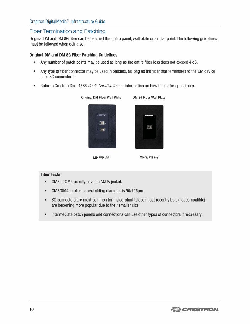
Fiber Termination and Patching
Original DM and DM 8G fiber can be patched through a panel, wall plate or similar point. The following guidelines must be followed when doing so.
Original DM and DM 8G Fiber Patching Guidelines
• Any number of patch points may be used as long as the entire fiber loss does not exceed 4 dB.
• Any type of fiber connector may be used in patches, as long as the fiber that terminates to the DM device uses SC connectors.
• Refer to Crestron Doc. 4565 Cable Certification for information on how to test for optical loss.
Original DM Fiber Wall Plate DM 8G Fiber Wall Plate
MP-WP186 MP-WP187-S
Fiber Facts
• OM3 or OM4 usually have an AQUA jacket.
• OM3/OM4 implies core/cladding diameter is 50/125µm.
• SC connectors are most common for inside-plant telecom, but recently LC’s (not compatible) are becoming more popular due to their smaller size.
• Intermediate patch panels and connections can use other types of connectors if necessary.
Crestron DigitalMedia™ Infrastructure Guide
800-237-2041 | crestron.com/digitalmedia 11
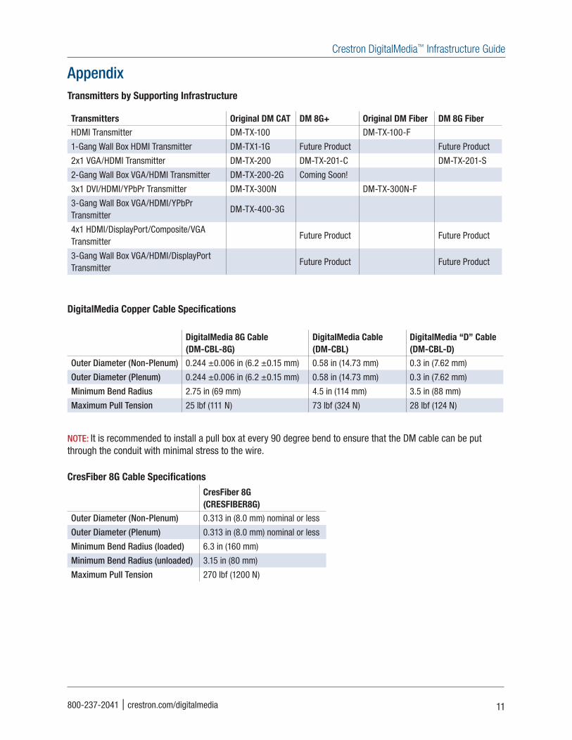
AppendixTransmitters by Supporting Infrastructure
Transmitters Original DM CAT DM 8G+ Original DM Fiber DM 8G FiberHDMI Transmitter DM-TX-100 DM-TX-100-F
1-Gang Wall Box HDMI Transmitter DM-TX1-1G Future Product Future Product
2x1 VGA/HDMI Transmitter DM-TX-200 DM-TX-201-C DM-TX-201-S
2-Gang Wall Box VGA/HDMI Transmitter DM-TX-200-2G Coming Soon!
3x1 DVI/HDMI/YPbPr Transmitter DM-TX-300N DM-TX-300N-F
3-Gang Wall Box VGA/HDMI/YPbPr Transmitter
DM-TX-400-3G
4x1 HDMI/DisplayPort/Composite/VGA Transmitter
Future Product Future Product
3-Gang Wall Box VGA/HDMI/DisplayPort Transmitter
Future Product Future Product
DigitalMedia Copper Cable Specifications
DigitalMedia 8G Cable (DM-CBL-8G)
DigitalMedia Cable (DM-CBL)
DigitalMedia “D” Cable (DM-CBL-D)
Outer Diameter (Non-Plenum) 0.244 ±0.006 in (6.2 ±0.15 mm) 0.58 in (14.73 mm) 0.3 in (7.62 mm)
Outer Diameter (Plenum) 0.244 ±0.006 in (6.2 ±0.15 mm) 0.58 in (14.73 mm) 0.3 in (7.62 mm)
Minimum Bend Radius 2.75 in (69 mm) 4.5 in (114 mm) 3.5 in (88 mm)
Maximum Pull Tension 25 lbf (111 N) 73 lbf (324 N) 28 lbf (124 N)
NOTE: It is recommended to install a pull box at every 90 degree bend to ensure that the DM cable can be put through the conduit with minimal stress to the wire.
CresFiber 8G Cable SpecificationsCresFiber 8G (CRESFIBER8G)
Outer Diameter (Non-Plenum) 0.313 in (8.0 mm) nominal or less
Outer Diameter (Plenum) 0.313 in (8.0 mm) nominal or less
Minimum Bend Radius (loaded) 6.3 in (160 mm)
Minimum Bend Radius (unloaded) 3.15 in (80 mm)
Maximum Pull Tension 270 lbf (1200 N)
Crestron World Headquarters15 Volvo DriveRockleigh, NJ 07647800.237.2041201.767.3400Fax: 201.767.1903crestron.com
Crestron International HeadquartersOude Keerbergsebaan 22820RijmenamBelgium+32.15.50.99.50Fax: +32.15.50.99.40crestron.eu
Crestron Asia HeadquartersRoom 2501, 25/F, Westin CentreNo. 26 Hung To RoadKwun TongHong Kong+852.2341.2016Video Ph: +852.2373.7530Fax: +852.2344.0889crestronasia.com
Crestron Latin America HeadquartersBlvd. Manuel Avila Camacho No 37-1ACol. Lomas de ChapultepecCP 11560 México DF+55.5093.2160Fax: +55.5093.2165crestronlatin.com
Printed in USA Doc.4556 5/11
Products manufactured in the United States.All brand names, product names and trademarks are the property of their respective owners.Specifications subject to change without notice. Refer to www.crestron.com for detailed specifications.©2011 Crestron Electronics, Inc.
![3-Series 4K DigitalMedia Presentation System 300® 4K DigitalMedia™ Presentation System 300 ... all-in-one 4K AV presentation system for classrooms ... [2], and the DM …](https://img.pdfslide.us/doc/110x75/5aea30b57f8b9ac3618d71c2/3-series-4k-digitalmedia-presentation-system-4k-digitalmedia-presentation-system.jpg)

![3-Series DigitalMedia Presentation System 300 · easy setup with no programming required [1] ... and Android ™ control app ... DMPS3-300-C 3-Series® DigitalMedia™ Presentation](https://img.pdfslide.us/doc/110x75/5b9815ef09d3f2e3488ceeab/3-series-digitalmedia-presentation-system-300-easy-setup-with-no-programming.jpg)


![Video Shooting Techniques [digitalmedia]](https://img.pdfslide.us/doc/110x75/5464739aaf7959f2058b67bd/video-shooting-techniques-digitalmedia.jpg)