Embed Size (px)
Citation preview

DeNew
esignw Constr
n Guruction
uide& Majo
elineor Reno
Facilities Se
es ovations
Rev
ervices and
s
vised: 20 Oct
Campus De
tober 2015
velopment

DesignGuidelines
Vancouver Island University
REVISION DATE: October 20, 2015
2
TableofContents
Introduction .................................................................................................................................................. 4
1 Code Analysis ........................................................................................................................................ 5
2 Geotechnical Design Criteria ................................................................................................................. 8
3 Site Development ................................................................................................................................ 11
5 Building Enclosure (Envelope) ............................................................................................................ 19
7 Structural Design Criteria .................................................................................................................... 22
9 Safety and Security ............................................................................................................................. 26
11 Fall Protection ................................................................................................................................. 28
13 Access Control ................................................................................................................................. 29
15 Room Numbering ............................................................................................................................ 32
16 Building Entrances .......................................................................................................................... 33
18 Offices ............................................................................................................................................. 35
20 Classrooms ...................................................................................................................................... 37
22 Computer Labs ................................................................................................................................ 47
24 Support Spaces ................................................................................................................................ 49
26 Custodial Spaces ............................................................................................................................. 50
28 Maintenance Rooms ....................................................................................................................... 52
30 Service Entrances ............................................................................................................................ 53
32 Mechanical Rooms .......................................................................................................................... 54
34 Electrical Rooms .............................................................................................................................. 56
36 Communication Rooms ................................................................................................................... 57
38 Emergency Eyewash and Safety Showers ....................................................................................... 59
40 Washrooms ..................................................................................................................................... 60
42 Shower Room .................................................................................................................................. 64
44 Unoccupied Spaces ......................................................................................................................... 65
46 Corridors ......................................................................................................................................... 66
48 Interior Stairs .................................................................................................................................. 67
50 Vending Machines & Lockers .......................................................................................................... 68
52 Recycling ......................................................................................................................................... 69
DesignGuidelines
Vancouver Island University
REVISION DATE: October 20, 2015
3
54 Exterior Steps .................................................................................................................................. 70
56 Bicycle Racks ................................................................................................................................... 71
58 Wireless Communications .............................................................................................................. 72
60 Parking Control Equipment ............................................................................................................. 73
62 Electrical .......................................................................................................................................... 74
64 Mechanical ...................................................................................................................................... 88

DesignGuidelines
Vancouver Island University
REVISION DATE: October 20, 2015
4
DesignGuidelines
Introduction
The Vancouver Island University Design Guidelines are an objective‐based tool, intended to
provide direction and establish parameters for the design and development of all Vancouver
Island University facilities. The purpose of the Design Guidelines is to promote suitable design
based on institutional needs and desires, and to discourage inappropriate design based on
experience and precedent.
The Design Guidelines specifically target design criteria and expectations – for example: the
width for pedestrian pathways & vehicle access; size requirements for classrooms, offices, and
other areas; provision‐of and access‐to janitorial & support spaces; design & layout preferences
for washrooms, and so on.
The Design Guidelines work together with the Performance Specifications (which specify
products and procedures, including: finishes, fixtures, equipment, hardware and other similar
building components) to ensure quality and consistency in building design and to maximize
quality and value by ensuring uniformity, compatibility and maintainability.

DesignGuidelines
Vancouver Island University
REVISION DATE: October 20, 2015
5
1 CodeAnalysisProvide a complete code analysis addressing all design criteria with the following minimum requirements:
DIVISIONB,PART3‐FIREPROTECTION,OCCUPANTSAFETYANDACESSIBILITY
1.1 GENERAL1.1.1 Classification of Buildings or Parts of Buildings by Major Occupancy
1.1.2 Multiple Occupancy Requirements
1.1.3 Combustible Construction
1.1.4 Non‐Combustible Construction
1.1.5 Fire‐Resistance Ratings
1.1.6 Fire Separations and Closures
1.1.7 Building Services in Fire Separations and Fire‐Rated Assemblies
1.1.8 Firewalls
1.1.9 Fire Stops in Concealed Spaces
1.1.10 Flame‐Spread Rating and Smoke Developed Classification
1.1.11 Interior Finish
1.1.12 Roof Assemblies
1.1.13 Roof Covering
1.1.14 Fabrics
1.1.15 Occupant Load
1.2 BUILDINGFIRESAFETY1.2.1 General
1.2.2 Building Size and Construction Relative to Occupancy
1.2.3 Spatial Separation, Exposure Protection
1.2.4 Fire Alarm and Detection Systems
1.2.5 Provisions for Firefighting
1.2.6 Lighting and Emergency Power Systems
1.2.7 Mezzanines and Openings Through Floor Assemblies
1.3 SAFETYWITHINFLOORAREAS1.3.1 All Floor Areas
1.3.2 Assembly Occupancy
1.3.3 Care or Detention Occupancy
1.3.4 Residential Occupancy
1.3.5 Industrial Occupancy

DesignGuidelines
Vancouver Island University
REVISION DATE: October 20, 2015
6
1.4 Exits1.4.1 General
1.4.2 Number and Location of Exits from Floor Areas
1.4.3 Width and Height of Exits
1.4.4 Fire Separation of Exits
1.4.5 Exit Signs
1.4.6 Types of Exit Facilities
1.4.7 Fire Escapes
1.5 VerticalTransportation1.5.1 General
1.5.2 Standards
1.5.3 Fire Separations
1.5.4 Dimensions and Signs
1.6 SERVICEFACILITIES1.6.1 General
1.6.2 Service Rooms
1.6.3 Vertical Service Spaces and Service Facilities
1.6.4 Horizontal Service Spaces and Service Facilities
1.6.5 Air Duct and Plenum Systems
1.7 HEALTHREQUIREMENTS1.7.1 Height of Rooms
1.7.2 Plumbing Facilities
1.7.3 Medical Gas Piping Systems
1.8 BUILDINGREQUIREMENTSFORPERSONSWITHDISABILITIES*Note: Refer to Vancouver Island University Accessible Facility Design Criteria for requirements which supercede the Building Code.
1.8.1 General
1.8.2 Classification Requirements
1.8.3 Design Requirements
1.8.4 Alterations and Additions to Existing Buildings
1.9 OBJECTIVESANDFUNCTIONALSTATEMENTS1.9.1 Alternative Solutions (if applicable)

DesignGuidelines
Vancouver Island University
REVISION DATE: October 20, 2015
7
DIVISIONB,PART4‐STRUCTURALDESIGN
1.10 STRUCTURALLOADSANDPROCEDURES1.10.1 General
1.10.2 Specified Loads and Effects
1.10.3 Limit States Design
1.10.4 Dead Loads
1.10.5 Live Loads Due to Use and Occupancy
1.10.6 Loads Due to Snow, Ice and Rain
1.10.7 Wind Load
1.10.8 Earthquake Load and Effects
1.11 DESIGNREQUIREMENTSFORSPECIALSTRUCTURES1.11.1 Parking Structures
1.12 OBJECTIVESANDFUNCTIONALSTATEMENTS1.12.1 Alternative Solutions (if applicable)
DesignGuidelines
Vancouver Island University
REVISION DATE: October 20, 2015
8
2 GeotechnicalDesignCriteria
2.1 REQUIREMENTSFORGEOTECHNICALREPORTS
2.1.1 A geotechnical report (the “Report”) is required to confirm that the land may be used safely for the use intended without an undue risk of hazards. The Report shall be prepared by a Professional Engineer registered in British Columbia with qualifications and experience in geotechnical engineering (the “Engineer”).
2.1.2 The Engineer shall inspect the project area, provide & investigate sub‐surface conditions via multiple test pits, and supervise the geotechnical site investigations. The Report shall clearly state all relevant restrictions, conditions and/or limitations to the proposed development of the land. The geotechnical site investigations and the Report shall be completed in accordance with good engineering practice. The Report shall address the following minimum criteria:
2.1.2.1 Identify any hazards which may affect the safe development of the land
including, but not limited to: (a) flooding (b) ground water flows (c) mud flows (d) erosion (e) subsidence (f) land slip (g) earthquake (h) avalanche
2.1.2.2 Provide recommendations to reduce the risk of damage to the land, buildings
and the Works and Services as per the following: (a) identify any part of the Works and Services which require inspection by
specialized personnel and outline a recommended inspection program during the development of the land;
(b) additional geotechnical investigations and reports; (c) restriction of the use of the land, buildings or the Works and Services; (d) remediation of any unstable or potentially unsuitable soils; (e) additional reports during the maintenance period.
2.1.2.3 Establish a safe setback line from any watercourses, steep slopes or hazard
areas to protect the land, buildings and inhabitants from the risk of injury or damage that may, in the opinion of the Engineer, be caused by the hazards of flooding, erosion, land slip, rock fall, subsidence, earthquake, mud flows or any combination thereof.
DesignGuidelines
Vancouver Island University
REVISION DATE: October 20, 2015
9
2.1.2.4 Quantify the risks of a geotechnical failure or any substantial hazard.
2.1.2.5 Certify “the land is safe for the use intended.”
2.1.3 The Engineer’s Recommendations and Conclusions in the Report must:
2.1.3.1 acknowledge that Vancouver Island University, its administration and project
design consultants may rely upon the Report when making decisions on land development building design;
2.1.3.2 certify “the land is safe for the use intended” with the probability of a
geotechnical failure resulting in property damage of less than 10 percent (10%) in 50 years; with the exception of geohazard assessments due to a seismic event which are to be based on a 2 percent (2%) probability of exceedance in 50 years;
2.1.3.3 identify any deficiency in the design of the buildings, the proposed water,
sewer, drainage, access and road works (the “Works and Services”) or the construction standards intended for the development;
2.1.3.4 prescribe the geotechnical works and any changes in the standards of the design
of the development which are required to: (a) ensure the land, buildings and the Works and Services are developed safely
for the use intended; (b) maintain the safety of the land, buildings and any Works and Services
throughout the course of the development.
2.1.3.5 The Report and two duplicate copies shall be provided to the Vancouver Island University Facilities Services & Campus Development.
2.2 SEISMICDESIGN2.2.1 Seismic Zoning for the Project area will be as defined in Division B, Subsection 1.1.3 of
the BC Building Code (BCBC), current edition.
2.2.2 Liquefaction potential of the sub soils will be evaluated for structures, walls and
embankments, and the design will incorporate ground improvements and other
methods of addressing potential liquefaction.

DesignGuidelines
Vancouver Island University
REVISION DATE: October 20, 2015
10
2.3 FOUNDATION/RETAININGWALLDESIGNCRITERIA2.3.1 The minimum Factor of Safety against:
(a) bearing capacity failure;
(b) sliding;
(c) overturning;
under static loading, shall be specified by the design Engineer.
2.4 SETTLEMENTANALYSIS2.4.1 Settlement analysis of structures shall be performed. Foundations will be designed such
that differential settlement between adjacent footings is limited to the amount
tolerable as specified by the Structural Engineer.

DesignGuidelines
Vancouver Island University
REVISION DATE: October 20, 2015
11
3 SiteDevelopment
3.1 GENERALREQUIREMENTS3.1.1 All work will be designed and constructed in accordance with the Project Requirements
as outlined in the RFP and VIU’s current directives, standards, specifications, practices,
policies and procedures in effect at the date of execution of the Contract Agreement, or
specified elsewhere.
3.1.2 All work shall be designed and sealed by a qualified Professional Engineer registered
with the Province of British Columbia. Sealed Letters of Assurance shall be provided in
accordance with Division C, Article 2.2.7.2 for all work.
3.1.3 The contractor shall be responsible for identifying the location and availability of
existing services, as well as the connection of proposed services to existing services.
3.2 WORKTOBEINCLUDED3.2.1 The scope of work includes the provision of the full and complete design, the supply of
all materials and the performance of all work necessary or appropriate regarding the
site, including the provision of entrance walkways, lighting, topsoil and seed.
3.2.2 Provide plan(s) locating all existing and proposed site services, including:
3.2.2.1 Fencing and Hoarding;
3.2.2.2 Water Supply;
3.2.2.3 Sanitary Sewer;
3.2.2.4 Storm Sewer;
3.2.2.5 Underground electrical Services/Conduits and Utilities;
3.2.2.6 Natural Gas Service;
3.2.2.7 Parking lot layout and lighting;
3.2.2.8 Drainage/holding areas for treatment.
3.2.3 Provide cross sections of parking areas, building and site grading indicating how the site
will be developed. Indicate general overall dimensions.
3.3 FENCINGANDHOARDING3.3.1 Supply, install and maintain a continuous construction fence around the perimeter of
the work area. Fencing shall be 1800mm high portable wired fencing. Fencing shall be
suitably braced. Provide access gates for vehicle and persons as required for
construction and emergency access.
3.3.2 Provide fencing and hoarding to maintain safe exit routes from existing and completed
parts of the work.

DesignGuidelines
Vancouver Island University
REVISION DATE: October 20, 2015
12
3.3.3 Provide and maintain 1200mm high barricades around the drip lines of trees adjacent to
construction activities to protect trunk, limbs and roots from damage.
3.4 DRAINAGE3.4.1 Design grading to provide adequate surface drainage, do not drain onto adjacent
properties or structures.
3.4.2 Provide supplementary drainage system where adequate surface drainage is not
possible by grading alone.
3.4.3 Slope grades away from buildings.
3.4.4 Prepare and submit a formal sediment and storm water control plan for the project to
VIU for review and approval. This report will address and resolve any downstream
erosion concerns. As part of this exercise, the existence of any on‐site springs must be
confirmed and (as required) mitigation requirements addressed in the detailed design of
the Project.
3.4.5 Adhere to the standards for sediment and storm water control outlines in the jointly
published MOWLAP/DFO “Land Development Guidelines for the Protection of Aquatic
Habitat”.
3.4.6 The Proponent is required to complete an analysis of the downstream storm system to
ensure that adequate capacity for the five‐year post development flows (minor system)
and 100‐year post development flows (major system) is available from the site to an
acceptable outfall identified for this catchment and further, will be required to address
and resolve any downstream capacity and erosion concerns identified (a formal storm
water control plan must be prepared for the site and area).
3.4.7 Storm water quality must be addressed for all phases and/or components of the
construction before any inflow is directed to the downstream creek/fish habitat and
detention pond (e.g., parking lot oil and silt interceptors).
3.4.8 Approvals must be obtained from MOWLAP and VIU for all aspects of the drainage
design.
3.4.9 All municipal work to be constructed in accordance with the City of Nanaimo
Engineering Standards and Specifications, or other applicable municipal standards,
whichever is most stringent.
3.5 VEHICLEPARKING3.5.1 The Contractor is not required to provide vehicle parking.
3.6 STORMSEWER3.6.1 Storm sewer shall commence 1.0m outside building lines.
3.6.2 Design storm sewer to handle peak flows as per BC Plumbing Code, current edition and
good engineering practice.

DesignGuidelines
Vancouver Island University
REVISION DATE: October 20, 2015
13
3.6.3 Gravity flow storm sewer shall be sloped in the direction of flow to maintain a minimum
velocity of 0.9m per second.
3.6.4 Storm sewage system shall be designed complete with all accessories and
appurtenances such as catch basins, maintenance holes, lift stations, storm drainage
ponds/lagoons, silt traps, etc. Extras will not be considered during or after construction
if it is established that the system as designed will not function correctly.
3.6.5 Where conflicts exist between local codes and standards and provincial & national
Plumbing and Building Codes; design shall comply with the most stringent.
3.6.6 Confirm location and elevation of existing storm system. Relocate/reroute existing
storm sewers located under the proposed building site, or as required to complete the
work and to meet or exceed existing conditions. Any system deemed not in use to be
removed or filled with grout.
3.6.7 Provide new catch basins and curbs/gutter as required for site drainage. Make
connection to existing systems where required.
3.6.8 Clean, Flush and Video Inspect all pipe‐work as follows:
3.6.8.1 Before flushing and testing, ensure sewer system is completely finished and
make arrangements with Contract Administrator to schedule testing.
3.6.8.2 Water may be supplied from Municipal fire hydrants upon application for a
Hydrant Use Permit.
3.6.8.3 Municipal Approval is required prior to discharging water into municipal sewers
or drainage ditches.
3.7 VIDEOINSPECTION3.7.1 All storm sewers less than 900mm in diameter shall be video inspected once installation
is complete. The video inspection report shall be in the form specified by the Contract
Administrator. Copies of the videos and written report shall be forwarded to the
Contract Administrator once available.
3.7.2 Should video inspection indicate apparent deficiencies, the Contract Administrator may
direct the Contractor to perform additional testing as follows:
3.7.2.1 passing a rubber ball, mandrel or test plug having a minimum dimension of 95%
of diameter of sewer pipe completely through pipes and appurtenances.
3.7.2.2 providing a light test in lieu of item 3.7.2.1 at the discretion of the Contract
Administrator.
3.7.3 All work shall be installed to the following standards:
3.7.3.1 Repair all deficiencies and visible leaks.
3.7.3.2 Repair procedures and materials are subject to approval of the Contract
Administrator.
3.7.3.3 The Contract Administrator reserves right to require the Contractor to replace
defective installations at the sole expense of the Contractor.
DesignGuidelines
Vancouver Island University
REVISION DATE: October 20, 2015
14
3.7.3.4 Test procedures including video inspection, shall be repeated and necessary
repairs shall be made until satisfactory results are obtained.
3.7.4 Acceptable Ponding:
3.7.4.1 Connections: 10mm maximum ponding over 3m length of pipeline.
3.7.4.2 Mainline storm sewers:
(a) 300mm diameter or less: 20mm maximum ponding over 3m length of
pipeline.
(b) Greater than 300mm diameter: 30mm ponding over 3m length of pipeline.
3.8 SANITARYSEWER3.8.1 Where conflicts exist between local codes and standards, the BC Plumbing Code and the
National Building Code, design shall comply with the most stringent.
3.8.2 The sanitary sewage system is to commence 1.0 meters outside the subject or group of
buildings and shall be designed to handle the peak flow.
3.8.3 Gravity flow sanitary systems shall be sloped in the direction of flow to provide a
minimum velocity of 0.9 m per second.
3.8.4 Provide design plan and profile drawings showing pipe size, type, slope and depth.
3.8.5 Provide field testing of all pipes in accordance with the following:
3.8.5.1 Repair or replace pipe, pipe joint or bedding found defective.
3.8.5.2 When directed by the Engineer, draw tapered wooden plug with diameter of
50mm less than normal pipe diameter through the sewer to ensure that pipe is
free of obstruction.
3.8.5.3 Remove foreign matter from sewers and related appurtenances by flushing with
water.
3.8.5.4 Perform infiltration and exfiltration testing as soon as practicable after jointing
and bedding are complete, and service connections have been installed.
3.8.5.5 Carry out tests on each section of sewer between successive manholes including
service connections.
3.8.5.6 Install watertight bulkheads in a suitable manner to isolate the test section from
the remainder of the pipeline.
3.8.6 Exfiltration test:
3.8.6.1 Fill the test section with water in such a manner as to allow displacement of air
in line. Maintain under normal head for 24 hours to ensure absorption in pipe
wall is complete before test measurements are commenced.
3.8.6.2 Immediately prior to test period, add water to pipeline until there is a head of
1.0 m over the interior crown of the pipe measured at the highest point of the
test section; or when the water manhole is 1.0 m above static ground water
level, whichever is greater.
3.8.6.3 Duration of exfiltration test: 2 hours.

DesignGuidelines
Vancouver Island University
REVISION DATE: October 20, 2015
15
3.8.6.4 Water loss at end of test period: shall not exceed maximum allowable
exfiltration over any section of pipe between manholes.
3.8.6.5 Leakage: shall not exceed following limits in litres per hour per mm of diameter
per 100 m of sewer including service connections:
3.8.6.6 Exfiltration, based on 1000mm head: 0.175L
3.8.6.7 Repair and retest sewer lines as required, until test results are acceptable.
3.8.6.8 Repair visible leaks regardless of test results.
3.9 WATERSUPPLY3.9.1 Provide domestic and fire protection water distribution system in accordance with the
BC Building Code, BC Fire Code, BC Plumbing Code, National Building Code and as
specified herein.
3.9.2 Site Domestic Water Distribution:
3.9.2.1 System shall be designed to meet current demand requirements.
3.9.2.2 Piping shall be provided with valved isolation in accordance with local
standards. Butterfly valves shall not be used.
3.9.2.3 Piping shall be buried minimum 1.0 m cover.
3.9.2.4 Relocate/reroute existing water mains located under the proposed building site.
3.9.3 Site Fire Protection Water Distribution:
3.9.3.1 Provide minimum 150mm fire protection service to the building separate from
the building domestic water service.
3.9.3.2 Provide hydrants at locations as per municipal standards. Hydrant quick‐
connects shall meet municipal standards, matching existing types.
3.9.3.3 All pipes, valves, hydrants shall be supplied and installed in accordance with
applicable CWWA and AWWA Standards.
3.9.3.4 Install thrust blocks at all bends, valves, hydrants and fittings.
3.9.3.5 Test all water mains in accordance with AWWA Standards.
3.9.3.6 Provide all valves with Valve boxes and chambers in accordance with municipal
standards.
3.9.3.7 Provide air and vacuum release and chambers at the high point in the system.
3.9.3.8 Complete a flow test on the municipal side of the connection.
3.10 WATERMAIN3.10.1 The Contractor shall confirm water fire flow volumes required for the development due
to pressure zone boundaries.
3.10.2 The Contractor is responsible to size and connect to existing service.

DesignGuidelines
Vancouver Island University
REVISION DATE: October 20, 2015
16
3.11 SITELIGHTING3.11.1 Site lighting for parking lots, roads and pedestrian walkways to be designed in
accordance with WorkSafe BC requirements, Canadian Electrical Code, IESNA Lighting
Handbook Appendix D8‐Electrical and as described herein.
3.12 LANDSCAPING3.12.1 Landscaping will consist of regrading the site to provide positive drainage away from
building, supply and placement of a minimum of 150mm of topsoil and seeding. Provide
landscape cloth in flower bed areas under growing area for weed control.
3.12.2 Bark mulch shall not be used.
3.13 TOPSOIL3.13.1 Provide screened topsoil for all landscaped areas including: mixture of minerals,
particulate, microorganisms and organic matter which provide a suitable medium to
support the intended plant growth.
3.13.2 Topsoil shall not contain toxic elements or growth inhibiting materials.
3.13.3 Topsoil shall not contain crabgrass or other noxious weeds.
3.13.4 Topsoil shall be modified as necessary as required by the soil analysis to promote and
support healthy plant growth, such as, but not limited to adding: peat moss, sand,
limestone and fertilizers.
3.14 TREES3.14.1 Root systems of all remaining trees shall not interfere with site improvements including
sidewalks, parking areas, and underground utilities.
3.14.2 Trees provided shall not produce fruit, berries or any other type of outgrowth which
requires clean‐up (with the exception of leaves produced by deciduous trees).
3.15 PERMITSANDAPPROVALS3.15.1 The Contractor will be responsible for obtaining all required approvals and permits from
all agencies.
3.15.2 Outside utility agency approvals to service the site must be obtained by the Contractor
(e.g. Hydro, Telephone, Natural Gas, and Cable TV) prior to acceptance of the plans by
VIU and the preparation of the Servicing Agreement. Location of on‐site utility service
pads and corridors shall not conflict with any of the engineered services that have
priority traversing the site. The Contractor is advised to pursue these draft designs at
the same time as the on‐site mains and building are being designed.
3.16 UTILITIES3.16.1 Unless otherwise specified, all existing utilities shall be retained in service during and
subsequent to construction. The Contractor will be fully responsible to liaise,
DesignGuidelines
Vancouver Island University
REVISION DATE: October 20, 2015
17
coordinate and gain approvals from the relevant utility owners and provide all necessary
information and plans to the agencies following relocation or accommodation. All
utilities conflicting with the work must be adjusted and/or relocated. The Contractor
will be responsible to identify and resolve all service‐related issues pertaining to the
proposed development.
3.17 ENVIRONMENTALREQUIREMENTS3.17.1 The Contractor shall obtain all necessary approvals from the City of Nanaimo, the
Ministry of Water, Land and Air Protection (MoWLAP), and the Department of Fisheries
and Oceans (DFO) Canada and any other jurisdictional authority.
3.17.2 The Contractor shall adhere to the Memorandum of Understanding existing between
the City of Nanaimo, MoWLAP, and DFO Canada granting authority to the City of
Nanaimo to review and authorize land development projects in proximity of a
watercourse or any other environmentally sensitive area in the City of Nanaimo as
indicated in Schedule B, Bylaw 6000 (Official Community Plan) or Schedule G, Bylaw
4000, (Zoning Bylaw).
3.17.3 The Contractor shall act on behalf of VIU in meeting its obligations and will maintain
close liaison with the Environmental Coordinator of the City of Nanaimo, MoWLAP,
Fisheries and Oceans, and VIU to ensure that both the design and construction of the
Project are environmentally sound, and meet or exceed the requirements of applicable
environmental legislations. In addition, the Contractor shall comply with the
requirements of the following:
3.17.3.1 Federal and provincial environmental legislation. 3.17.3.2 MoWLAP environmental policy and procedural guidelines.
3.17.3.3 Any other governmental policy and procedural guidelines.
3.17.4 The Contractor shall secure all necessary environmental permits and satisfy the
requirements of government regulations and bylaws. The Contractor will be responsible
for implementing erosion and sedimentation control measures during construction,
including any temporary or seasonal shutdown periods and for implementing any
required environmental protection measures, This will include:
3.17.4.1 Habitat mitigation within the project requirements.
3.17.4.2 Run‐off and siltation control.
3.17.4.3 Preservation of natural watercourses and ravines.
3.17.4.4 Compliance with MoWLAP and Department of Fisheries and Oceans (DFO).
3.17.4.5 Sedimentation and erosion control measures in accordance with MoWLAP/DFO
“Land Development Guidelines for the Protection of Aquatic Habitat”.
3.17.5 Compliance with municipal environmental requirements.

DesignGuidelines
Vancouver Island University
REVISION DATE: October 20, 2015
18
3.18 SITESERVICINGDESIGNCRITERIA3.18.1 The following outlines the design criteria for the site servicing components of the
Project and defines the mandatory standards to which the design must adhere.
3.18.1.1 Reinforced Concrete Retaining Walls
(a) Design Code CAN/CSA‐S6‐88.
(b) Seismic design in accordance with current standards.
(c) Retaining wall type and surface treatment must be aesthetically pleasing.
(d) Design Service Life of 75 years.
3.18.1.2 Pedestrian Facilities
(a) Designed to be aesthetically pleasing and to tie into adjacent pedestrian
access ways in an acceptable manner.
(b) Concrete sidewalks to a minimum width @ 1.5m, minimum 100mm thick
over 75mm of 19mm crush base compacted to 98% SPD.
(c) Provide broom surface finish.
(d) Shared pedestrian/cyclist concrete pathway minimum width @ 1.8m (one‐
way), 2.4 m (two‐way) minimum 100mm thick over 75mm of 19mm crush
base compacted to 98% SPD.
(e) Handicapped access provisions required at access points to the building in
accordance with building code requirements.

DesignGuidelines
Vancouver Island University
REVISION DATE: October 20, 2015
19
5 BuildingEnclosure(Envelope)
5.1 DESIGNCRITERIA
5.1.1 APPROVALS,DESIGN,BUILDINGCODES5.1.1.1 Contract documents are to be prepared in accordance with the current edition
of the National Building Code, BC Building Code, the Ministry of Health, the
Ministry of Water, Land and Air Protection and all other authorities having
jurisdiction.
5.1.1.2 Include in submission, approval and payment for all necessary permits, fees and
licenses from authorities having jurisdiction.
5.1.1.3 Provide complete functional spatial planning based on the programmed unit
space sheets in this document.
5.1.1.4 All buildings shall be designed for a minimum 75 to 100‐year lifespan.
5.1.1.5 Buildings are expected to last a minimum of twenty (20) years without major
repairs; structural system is expected to last a minimum of forty (40) years
without major repairs.
5.1.2 ACCESSIBILITY5.1.2.1 All buildings shall be completely accessible for persons with disabilities.
5.1.2.2 Adhere to the VIU Accessible Facility Design Criteria.
5.1.2.3 Any deviations from the recommendations in the design are to be fully
documented and discussed with VIU Project Manager.
5.2 PERFORMANCEOFBUILDINGENVIRONMENT
5.2.1 BUILDINGENVELOPE5.2.1.1 Provide a building envelope which effectively separates the interior from
exterior environment by controlling the movement of air, water, heat and water
vapour to maintain the interior environmental condition while not
compromising or impairing the building envelope assemblies in any way.
5.2.1.2 The exterior envelope assemblies must effectively shed (drain away) water and
utilize materials and assemblies that: minimize deterioration when saturated,
and have superior drying capabilities.
5.2.1.3 Note that “Rainscreen” wall assemblies deal with wetting and drainage but
(alone) do not provide an adequate drying capability (refer to CMHC 99‐1007,
Stucco Clad Wall Drying Experiment).
5.2.1.4 Provide effective and continuous insulation within the building envelope
assembly. Insulate building envelope penetrations by pipes, ducts, conduits,
etc., per building code requirements. Window and door frames shall be

DesignGuidelines
Vancouver Island University
REVISION DATE: October 20, 2015
20
thermally broken. Eliminate all direct paths of head conductance by using
adequate insulation, air spaces between components, or other acceptable
means to prevent thermal bridging through the exterior envelope.
5.2.1.5 The building envelope shall resist, in accordance with building code
requirements, air leakage caused by static and dynamic air pressures across the
exterior walls, soffits, roof assemblies, windows, glass, doors, pipe, duct,
conduit or other penetrations or interruptions of the envelope system or
assembly.
5.2.1.6 Energy conservation techniques shall be incorporated without jeopardizing the
function and performance of building. Use ASHRAE Energy Standards to explore
innovative solutions for electrical and mechanical systems to provide optimal
environmental conditions, and reduced energy consumption for the building.
Ensure interior humidity is maintained at an appropriate level to prevent
condensation within the building envelope.
5.2.1.7 Provide locked access to all flat roofs from internal common areas.
5.2.1.8 Prime Consultant must engage and pay or all fees associated with a qualified
roof inspection firm to review and certify the roof design during the design
stage of the facility.
Recommended firm is :
Westcoast Roof Inspection Services Ltd.
665 Butterfield Road
Mill Bay, BC V0R 2P4
Phone: 250‐743‐2913
Fax: 250‐743‐2973
E‐mail: [email protected]
5.2.2 MATERIALSANDWORKMANSHIP5.2.2.1 Materials and workmanship shall comply with recognized Canadian
Construction Standards and those of the Provincial and/or Canadian trade
associations wherever possible. Where no standards are applicable,
workmanship shall comply with top industry standards.
5.2.2.2 Include and specify the services of recognized, independent inspection
consultants for the Building Envelope and for material application inspection
services provided by recognized Industry Associations. These service agents
shall be acceptable to Vancouver Island University.
5.2.2.3 Consideration should be given to selecting appropriate materials and systems,
which are compatible to the various building environments. Assemblies and

DesignGuidelines
Vancouver Island University
REVISION DATE: October 20, 2015
21
materials shall be designed to minimize the operating and maintenance life‐
cycle costs, while also providing durability for the expected building life.

DesignGuidelines
Vancouver Island University
REVISION DATE: October 20, 2015
22
7 StructuralDesignCriteria
7.1 CAST‐IN‐PLACECONCRETE
7.1.1 SCOPEOFWORK7.1.1.1 The forming, placing, reinforcing and finishing of concrete, as appropriate, to all
footings, foundations, piers, caissons, columns, suspended slabs, walls and slabs
on grade and deck as required to complete the project. All work shall be
completed in accordance with accepted standards of good practice appropriate
to its intended use.
7.1.2 DESIGNSTANDARDS7.1.2.1 The design of all concrete elements shall conform to the BC Building Code, and
all other applicable codes, bylaws and standards of practice.
7.1.3 MATERIALS
7.1.3.1 Concrete(a) All concrete floors within the building shall have a minimum
strength 25 MPa at 28 days with a specified water‐reducing
admixture for slump of 80 mm +/‐ 25mm. Concrete shall be
reinforced where required.
7.1.3.2 ReinforcingSteel(a) Reinforcing steel shall conform to CSA Standard G30.12 and shall
have minimum yield strength of 400 MPa. Welded wire mesh
reinforcing shall comply with CSA G.30.5, and shall be used in floor
slabs. Wire mesh shall be supplied in flat sheets only.
7.1.3.3 Workmanship(a) All workmanship shall conform to the highest standards of practice.
7.1.4 FOUNDATIONS
7.1.4.1 ConcreteFoundations(a) Foundations shall be constructed to the depth required to achieve
appropriate bearing capacity as indicated in a current Geotechnical
report, and shall be placed below the frost level & all exterior fill.
(b) For the Nanaimo Campus; spread footing foundations providing
support for structural columns, shall extend to a depth as indicated
in the Geotechnical Report prepared by Lewkowich Engineering

DesignGuidelines
Vancouver Island University
REVISION DATE: October 20, 2015
23
Associates Ltd, dated August 22, 2002. A Geotehcnical Engineer
shall review & confirm all metrics stated in the aforementioned
report to ensure the specific details of the site have been
considered & that all current codes are met.
7.2 PRECASTCONCRETE
7.2.1 DESIGNSTANDARDS7.2.1.1 All design, fabrication and erection is to conform to applicable codes, laws,
bylaws and standards of practice.
7.2.2 MASONRY
7.2.2.1 MasonryWalls(a) All design and construction is to conform to applicable codes, laws,
bylaws and standards of practice.
7.3 STRUCTURALSTEEL
7.3.1 SCOPEOFWORK7.3.1.1 Design and supply steel framed structures comprising structural steel roof and
wall framing systems to support all roof loads and lateral forces in accordance
with all codes, laws, bylaws and standards of practice.
7.3.1.2 Design and supply of conventional structural steel framing.
7.3.1.3 Design and supply of all miscellaneous steel framing.
7.3.1.4 Design and supply of loose lintels in masonry walls.
7.3.2 DESIGNSTANDARDS7.3.2.1 Steel structures shall be designed in accordance with CAN/CSA‐S16‐01 (including
supplement CAN/CSA‐S16S1‐04).
7.3.3 MATERIALS7.3.3.1 All structural steel shall comply with CAN/CSA G40.21‐04, Grade 300W.
7.3.3.2 Hollow structural sections shall comply with CAN/CSA G40.21‐04, Grade 350W.
7.3.3.3 Cold formed sections shall conform to CAN/CSA S136‐01 (including supplement
CAN/CSA‐S136S1‐04), Grade 450W.
7.3.3.4 Fasteners shall conform to ASTM A325‐09 for structural connections and
CAN/CSA G40.21‐04, Grade 500W for channels, sag rods and anchor bolts.
7.3.3.5 Welding shall conform to CSA W59, latest edition, and shall be performed by
qualified fabricators, licensed by the Canadian Welding Bureau and shall comply
with CSA W47.1, latest edition.
7.3.3.6 Hot dip galvanizing: galvanize steel, where indicated, to CSA G164‐M92.

DesignGuidelines
Vancouver Island University
REVISION DATE: October 20, 2015
24
7.3.3.7 Shear stud connectors: to CSA W59 latest edition.
7.3.3.8 Plant inspections are to be arranged for the quality assurance inspection firm.
7.3.4 ERECTION7.3.4.1 Clean with mechanical brush and touch up shop primer to bolts, rivets, welds
and burned or scratched surfaces at completion of erection.
7.3.4.2 Erection inspections (tolerances, bolt torque etc.) to be arranged for the quality
assurance inspection firm.
7.3.5 FINISHES7.3.5.1 Finish steel members appropriately for their applicable service environment.
7.4 ROOFPURLINS/STEELJOISTS
7.4.1 SCOPEOFWORK7.4.1.1 Design and supply of roof purlins and/or open web steel joist, and diagonal and
horizontal bridging members to roof to carry snow, roofing, sprinklers and
mechanical equipment loads in accordance with all applicable codes, laws,
bylaws, standards of practice and CAN/CSA S136‐01 (including supplement
CAN/CSA‐S136S1‐04) including requirements for uplift due to wind loads.
7.4.2 MATERIALS7.4.2.1 Structural steel to conform to CAN/CSA G40.21‐04, Grade 300W.
7.4.2.2 Cold formed shapes to conform to CAN/CSA S136‐01 (including supplement
CAN/CSA‐S136S1‐04) Grade 450W.
7.4.2.3 Welding to conform to CSA W59, latest edition ‐ Welded Steel.
7.5 STEELDECK
7.5.1 SCOPEOFWORK7.5.1.1 Supply and installation of zinc coated metal deck complete with edge supports
and reinforcement at openings for all flat roof areas.
7.5.2 DESIGNSTANDARDS7.5.2.1 Design of deck to conform to CAN/CSA S136‐01 (including supplement
CAN/CSA‐S136S1‐04) ‐ Cold Formed Structural Members.
7.5.3 MATERIALS7.5.3.1 Deck shall be ZF075 wipe coat steel sheet conforming to ASTM standard A464M
specification for steel sheet, zinc coated structural quality.

DesignGuidelines
Vancouver Island University
REVISION DATE: October 20, 2015
25
7.5.3.2 Installation of deck to conform to CSSBI “Standard for Steel Roof Deck” to
provide anchorage of roof deck for supporting framing to resist the uplifts
specified in all applicable codes, laws, bylaws and standards of practice.
7.5.4 ERECTION7.5.4.1 Erect steel deck in accordance with manufacturer’s instructions.
7.5.4.2 Immediately after deck is permanently secured in place, touch up metallic
coated top surface with primer where scorched by welding.
7.5.5 CONNECTIONS7.5.5.1 Install connections in accordance with CSSB1 Steel Roof Deck, 10M‐86 and
Composite Steel Deck, 12M‐84 and in accordance with design requirements for
diagram action.

DesignGuidelines
Vancouver Island University
REVISION DATE: October 20, 2015
26
9 SafetyandSecurity
9.1 GENERAL9.1.1 Personnel safety and security are important values that can be achieved and enhanced
by prudent planning and design.
9.2 AWARENESSOFTHESURROUNDINGENVIRONMENT9.2.1 Persons should have the ability to see and to understand the surrounding environment
through unobstructed sightlines, adequate lighting.
9.2.2 Crime Prevention Through Environmental Design (CPTED) principles should be
considered during design to identify potentially hazardous environmental situations to
avoid confined and hidden areas.
9.3 VISIBILITYOFOTHERS9.3.1 The ability to be seen by others should be maximized by reducing isolation, improving
the land‐use mix, strategically placing activity generating elements, and creating a sense
of ownership through maintenance and management of the built environment.
9.4 FINDINGHELP9.4.1 In the event of an emergency, the ability to communicate, find help, or escape when in
danger is of critical importance. The following features should be observed as part of
the overall design to enhance personnel safety and security.
9.5 LIGHTINGANDVISIBILITY9.5.1 Light fixtures shall be placed to eliminate areas of potential entrapment, shall provide a
uniform level of lighting and shall minimize the contrast between light and shadow
areas.
9.5.2 Light fixtures shall be resistant to vandalism and shall be easy to maintain.
9.5.3 Perimeter wall surfaces should be light in colour, to improve light reflection & visibility
in public spaces.
9.6 STAIRLIGHTING9.6.1 General lighting in stairways shall be connected to emergency power.
9.7 PATHWAYS(INTERIORANDEXTERIOR)9.7.1 Lighting levels shall be bright enough to allow an individual to see and identify a person
15.0 m ahead.
9.7.2 Lighting levels shall provide minimum contrast between light and shadow areas.
9.7.3 Lighting levels shall be maintained along a pathway to provide an equivalent level of
safety along the length of the path identical to that at the beginning of the path.

DesignGuidelines
Vancouver Island University
REVISION DATE: October 20, 2015
27
9.7.4 Temporary lighting shall be provided on hoarding around construction sites.
9.7.5 Low‐level lighting within shrubbery and landscaping elements should be included to
complement design and improve safety.
9.8 SIGHTLINES9.8.1 All Vancouver Island University buildings and surrounding areas shall be designed to
maximize sightlines for pedestrians in all directions.
9.8.2 Maximize clear glazing in areas such as stairwells, elevator lobbies and entrances to
offices and work areas.
9.8.3 Landscape elements should be selected and located to not impede long views.
9.8.4 Building exterior design and placement should maximize the user’s ability to overlook
and casually survey public spaces.
9.9 ENTRAPMENTANDMOVEMENTPREDICTORS9.9.1 Areas of entrapment shall be avoided. Such areas include:
9.9.1.1 single entrance/exit offices in areas of low traffic;
9.9.1.2 vulnerable areas such as where student counseling takes place;
9.9.1.3 areas where researchers work at night or during off hours;
9.9.1.4 unlit recesses;
9.9.1.5 corners or alcoves;
9.9.1.6 small structures (sheds, storage areas) which are unlit or unlocked.
9.9.2 Washrooms, which are located in low activity areas, are potential entrapment areas,
especially if the entrance configuration is complicated and communication to a corridor
is difficult. Single‐use washrooms are a better option in low activity areas.
9.9.3 Structures, which create potential entrapment areas, shall be avoided. In enclosed
public spaces, columns rather than shear walls should be used as structural members.
9.9.4 If a potential entrapment area cannot be avoided, consideration must be given to
communication needs, particularly for emergency assistance.

DesignGuidelines
Vancouver Island University
REVISION DATE: October 20, 2015
28
11 FallProtection
11.1 GENERAL11.1.1 Review fall protection anchorage requirements with Facilities Management. Each
employee on a walking/working surface (horizontal and vertical surfaces) with
unprotected side or edge, which is 1,800 mm or more above a lower level, shall be
protected from falling by the use of guardrail systems with toe boards or a personal fall
arrest system. Examples of such work include, but are not limited to:
11.1.1.1 Maintenance on rooftop, such as: roof repair, unplugging roof drains, other
building system maintenance;
11.1.1.2 Work platforms that are designed to access and maintain specific equipment;
11.1.1.3 Any other walking and working surface not otherwise addressed with the
potential to fall more than 1,800 mm to another level/surface.
11.1.2 Anchorage used for attachment of personal fall arrest equipment shall be independent
of any anchorage being used to support or suspend platforms, and designed as per
WorkSafe BC requirements.

DesignGuidelines
Vancouver Island University
REVISION DATE: October 20, 2015
29
13 AccessControl
13.1 GENERAL13.1.1 The intent of the access control system is to control and track access and entry to the
entrances of the buildings and certain interior rooms/areas.
13.2 DESIGNREQUIREMENTS13.2.1 Request to Exit button is required at every magnetic lock installation. This will provide
redundancy in lieu of the “unlock on REX” programming feature.
13.2.2 Every auto door opener must be completely integrated with the access control
hardware to allow activation without the “unlock on REX” programming feature.
13.2.3 All conduit/wiring must be concealed with in wall/ceiling/window/door assemblies. Any
exposed work must be reviewed and approved by VIU prior to installation.
13.2.4 At a minimum, all exterior doors shall be piped with conduit to facilitate card readers,
magnetic contacts and other devices to be installed at a future date if not part of the
proposed scope of work. The as‐built documents shall clearly indicate the locations of
the conduits and major junction boxes.
13.2.5 Designers shall have a clear understanding of the particular function of a Vancouver
Island University facility prior to designing an access control system for such facility.
Most buildings are occupied during normal working hours and are secured for the
evening. However access is required for certain buildings during night and off‐peak
hours which maintain classes during evenings, or provide support and library services.
Vancouver Island University teaching and research staff also require various levels of
access & security after hours. The following principles should be considered when
addressing access control:
(a) Access control shall be designed to maintain a separation between public, semi‐
public and private areas.
(b) Private areas, and other areas requiring higher levels of security (ie: private areas)
should only be accessible from semi‐private areas (interiors of suites) within a
building.
(c) Direct access to secure areas from major circulation corridors within a building
should be avoided.

DesignGuidelines
Vancouver Island University
REVISION DATE: October 20, 2015
30
13.3 ARCHITECTURAL
13.3.1 DOORS
13.3.1.1 Doorlocationdefinition:
(a) CardReaderDoor: Main building entrance;
High‐traffic secondary building entrances (ie: likely to be used for entry after
hours);
Entrances to Computer Labs, Science Labs, Lecture Theaters, Conference
Rooms;
Entrances to employee work areas;
Staff rooms.
(b) AutoLockdoor: Low‐traffic secondary building entrances that would not be used for after hour
entry.
All remaining doors to Computer Labs, Science Labs, Lecture Theaters,
Conference Rooms.
(c) ExitOnlyDoor:Exterior doors usually require by code that would only be used as exit only.
13.3.2 Doorequipmentrequirement:
(a) CardReaderDoor: Card reader;
Electronic locking device;
Door contacts;
REX sensor;
Request to exit button (for magnetic lock installations).
(b) AutoLockDoor: Electronic locking device;
Door contacts;
REX sensor;
Request for exit button (for magnetic lock installations).
(c) ExitOnlyDoor: Standard non‐electronic locking device;
DesignGuidelines
Vancouver Island University
REVISION DATE: October 20, 2015
31
Door contacts;
REX sensor.
(d) Elevator: Elevators & corridor on each floor shall be wired for card readers;
Confirm whether the following will be required with VIU Project Manager:
o Card reader in cab;
o Card reader in corridor on each floor.

DesignGuidelines
Vancouver Island University
REVISION DATE: October 20, 2015
32
15 RoomNumbering
15.1 GENERAL15.1.1 Every space within a facility shall have a room number approved by Facilities Services
and Campus Development.
15.1.2 The Architect shall provide a digital copy plus one hard‐copy of floor plans no later than
the preliminary design submission for the assignment of room numbers by VIU.
15.1.3 The assigned room numbers shall be incorporated into the construction documents
(including plans, specifications and any other applicable document).
15.1.4 The architect shall be responsible for obtaining the assigned room numbers. Additional
submittals are required if plans have changed since the preliminary design submission.
15.1.5 Door numbering shall relate to assigned room numbers in a logical sequence, such as
single doors being the same as room number, such as 101, 101A where assigned room
numbers have a suffix.
15.2 NUMBERINGCRITERIA15.2.1 Room numbers start at the main point of entry for a floor and increase as the user
proceeds clockwise throughout the building; 15.2.2 Classrooms, Laboratories, Computer Labs, Lecture Theatres and other large functions
are typically separated by multiples of 5; 15.2.3 Offices, Washrooms, Meeting Rooms and other smaller functions are typically separated
by multiples of 2 (occasionally 1 if necessary); 15.2.4 Rooms within rooms maintain the same number, but are also designated with a suffix
letter (ie: the first close‐door office within room 205, would become 205A); 15.2.5 Areas which are part of another area, but not separated by walls are designated with a
decimal point (ie: a kitchen within room 300 would be 300.1); 15.2.6 Elevators & Stairs are designated by number and floor (ie: Stairway #2, Third Floor = 2.3.
Elevator#1, Second Floor = 1.2) 15.2.7 For the purposes of clarity, workstations in open areas may be designated with letters
(ie: A, B, X, Y). VIU does not use these numbers in the future; they are simply added to help to quickly identify and locate furniture, equipment and other elements throughout the project.

DesignGuidelines
Vancouver Island University
REVISION DATE: October 20, 2015
33
16 BuildingEntrances
16.1 GENERAL16.1.1 Primary building entrances shall be located to reflect pedestrian routes and vehicular
drop off. All primary entrances shall be accessible (barrier‐free) for persons with
disabilities (barrier‐free).
16.2 ARCHITECTURAL
16.2.1 LOCATIONS1.2.1.2 Additional free floor space shall be made available adjacent to each barrier‐free
point of entry within the vestibule, or foyer if there is no vestibule. This space
shall be designated for a minimum of two wheelchair positions for alternative
transportation pickup, which shall have clear view of the designated vehicular
pickup/drop off. Public telephones shall be located adjacent to these areas for
users to contact private or public transportation sources.
1.2.1.3 Primary entrances shall be fully glazed with a clear view into the building and to
pick‐up/drop‐off areas.
16.3 DOORS/ENTRANCES/WINDOWS1.2.1.4 All exterior doors shall be of heavy‐duty commercial aluminum storefront to
correspond with VIU Performance Specifications Section 08 11 00.
1.2.1.5 Automatic openers shall be provided for all entrance doors that could
potentially be used by a person with disabilities.
1.2.1.6 Automatic door opener buttons shall be located in such a way that, upon
operation, the door is in clear view of the button, and the user does not need to
re‐position himself prior to passing through the door.
1.2.1.7 Access for glazing cleaning shall be reviewed with VIU Facilities Services.
16.4 FINISHES1.2.1.1 Incorporate floor mat (supplied by VIU) design for all building entrances to
ensure adequate function and aesthetics.
1.2.1.2 Ensure main entries are covered to protect occupants who are entering the
building from the elements. The covered area shall have adequate depth to
provide enough space for typical congestion during peak access periods.
1.2.1.3 Entrance protection shall be designed to divert rain and snow run off.

DesignGuidelines
Vancouver Island University
REVISION DATE: October 20, 2015
34
1.2.1.4 Ground surface at all entrances shall be designed to prevent water from
pooling.

DesignGuidelines
Vancouver Island University
REVISION DATE: October 20, 2015
35
18 Offices
18.1 GENERAL18.1.1 Offices shall be designed as to provide maximum flexibility for future adaptation. This
includes walls to underside of ceilings for ease of relocation.
18.1.2 All services in the office walls shall be fed from above (not the slab) to facilitate ease of
relocation. Electrical / Communication services shall be located to accommodate the
maximum number of potential office furniture configurations.
18.2 ARCHITECTURAL
18.2.1 LOCATIONSWITHINABUILDING1.2.1.1 Offices should be located within department areas to reduce, control and
monitor traffic by the area secretary/support staff.
1.2.1.2 Avoid locating offices adjacent to coffee and photocopy areas as these generate
distractions and noise.
18.2.2 ROOMSHAPE18.2.2.1 Typical open‐area offices shall be sized as follows:
(a) 4.5m2 (50 ft2) for task‐oriented requiring minimal space;
(b) 6.5m2 (70 ft2) for support;
(c) 7.5m2 (80 ft2) for standard faculty;
18.2.2.2 Typical enclosed offices shall be sized as follows:
(a) 7.5m2 (80 ft2) for standard faculty;
(b) 9.3m2 (100 ft2) for coordinators;
(c) 11.15m2 (120 ft2) for deans, directors or senior administrators;
(d) No wall should be less than 6’ in length;
(e) Maintain 12” clear behind office doors for freestanding
shelving/bookcase(s).
18.2.3 DOORS18.2.3.1 Doors must have a vision panel 152x609mm (6”x24”).
18.2.4 FINISHES18.2.4.1 Standard floor covering is low VOC carpet tile.
18.2.4.2 Allow for one accent paint colour (two colours in total).
18.3 ELECTRICAL
18.3.1 LIGHTINGANDLIGHTINGCONTROL18.3.1.1 Provide non‐glare lighting.

DesignGuidelines
Vancouver Island University
REVISION DATE: October 20, 2015
36
18.3.1.2 Provide one light switch for each office (up to double‐occupancy offices). Shall
be located beside the latching side of the door.
18.3.1.3 In shared offices of three or more, individual light control should be provided
(spec fixture).
18.3.1.4 Light switching shall be fed from above for ease of future relocation; slab feeds
are not permitted.
18.3.2 POWER,DATAANDVOICE18.3.2.1 Adhere to the VIU IT Design Guidelines for power, data and voice servicing
requirements.
18.3.2.2 All service locations shall be submitted and confirmed by VIU before final
drawings are issued for construction.
18.3.2.3 All outlets shall be fed from above for ease of future relocation; slab feeds are
not permitted.
18.4 MECHANICAL18.4.1 There shall be no more than three offices served by a single thermostat.
18.4.2 All thermostats shall be fed from above for ease of future relocation; slab feeds are not
permitted.
18.4.3 Return air must be ducted to a common return air plenum or system. Door
undercutting and door grilles are prohibited.
18.4.4 Operable windows are preferred for natural ventilation.
18.5 ACOUSTICS18.5.1 Walls between offices shall extend to the underside of the ceiling and shall have proper
back loading.
18.5.2 Wall cavities shall have absorbent material to reduce sound transmission.
18.5.3 Walls between offices and public corridors shall extend to the underside of the
structure/decking for security purposes.
18.5.4 Office doors to public corridors or noisy areas shall have an acoustic seal and automatic
door bottoms.
18.5.5 Dividing walls that intersect a window shall be acoustically treated.
18.5.6 Acoustic ceiling tiles shall be used.

DesignGuidelines
Vancouver Island University
REVISION DATE: October 20, 2015
37
20 Classrooms
20.1 GENERAL20.1.1 Classroom Sizes:
(a) Seminar or Small Classroom: up to 60m²
(b) Mid‐sized Classroom: 61m² to 117m² (655ft² to 1260ft²)
(c) Mid‐sized Tiered Classroom: 40m² to 100m² (430ft² to 1075ft²)
(d) Large Classroom: over 117m² (over 1260ft²)
(e) Lecture Theatre: over 100m² (over 1075ft²)
20.1.2 Classroom Occupancy:
(a) Seminar or Small Classroom: 2.5m² (27ft²) per student station
(b) Mid‐sized Classroom: 1.95m² (21ft²) per student station
(c) Mid‐sized Tiered Classroom: 1.65m² (18ft²) per student station
(d) Large Classroom: 1.50m² (16ft²) per student station
(e) Lecture Theatre: 1.80m² (19.5ft²) per student station
20.1.3 Unless otherwise noted all general purpose classrooms shall be have projection
capabilities (data/video projection).
20.1.4 Lecture rooms shall include instructional podium systems and controls for data and
video projection, internet and satellite connection, VCR or DVD drives, laptop
connection, room for podium computer system, control of lighting and sound.
20.1.5 Rooms should be designed for laptop connectivity as a future option, if not programmed
for immediate implementation.
20.1.6 Low‐glare whiteboards shall be used in all rooms; chalkboards are prohibited.
20.1.7 All classrooms shall comply with Universal Design Guidelines, and the VIU Accessible
Facility Design Criteria. Alternate seating locations for persons with disabilities shall be
provided.
20.2 ARCHITECTURAL
20.2.1 LOCATIONWITHINBUILDINGS20.2.1.1 Large classrooms should be located near major entrances on main/ground level
to enhance access and egress (for groups who use the facilities in the evenings
or on weekends), but far enough from noisy areas (which cause distractions).
20.2.1.2 If classrooms are located on higher levels, confirm all code requirements for
means of egress & exiting are met.
20.2.1.3 Classrooms should be concentrated on the main floor(s) of buildings to provide
students – disabled students in particular – more direct access. This also allows
for the convenient provision of support services.

DesignGuidelines
Vancouver Island University
REVISION DATE: October 20, 2015
38
20.2.1.4 Adequate circulation and reception space shall be provided outside the
entrance to large classrooms. Ensure that traffic flow to/from large group
spaces is not impeded by architectural obstacles, such as stairs, planters,
directories, displays or furnishings.
20.2.1.5 Small group spaces should be considered adjacent to classrooms for quick
break‐out discussions and easy reconvening of the full group. However, each
room type must function (access, systems) independently.
20.2.1.6 Equipment on carts and other class materials may be stored at a central
lockable depot. Several smaller classrooms may share a common storage,
preparation or projection room. If such common areas are provided, special
attention should be given to acoustically isolating the classrooms.
20.2.1.7 Halls, vestibules and lounges directly adjacent to classrooms shall not contain
vending machines. Noise from this equipment interferes with classroom use
when doors remain open.
20.2.1.8 Access to coffee & food services is desirable adjacent to large classrooms, as
they are often used for conference‐type functions, where such services are
used.
20.2.2 ROOMSHAPE20.2.2.1 When instruction originates from the instructor or screen, two key factors must
be considered in designing the shape of the room:
(a) visibility of the demonstration area (whiteboards, screens, podium)
from all points in the room, and
(b) acoustical optimization.
20.2.2.2 Room shape should be such that students are located as close as possible to the
instructor.
20.2.2.3 Small rooms should be near square in plan, preferably slightly longer than wide.
With increased size, banking (tiers) of the seats will be required and fanning of
the shape, with widening towards the rear.
20.2.2.4 A classroom shall not be too long nor too wide; the ideal dimension ratio of a
room is 1(H) : 1 ½(W) : 2 ½(L). The length of the room should not exceed its
width by more than 50%.
20.2.2.5 Classrooms (used extensively by instructors using audio‐visual/multimedia
presentations) shall be designed with the length dimensions of the room
approximately 1.5 times the width dimension. Rooms which are wider than
they are long provide unacceptable viewing angles for projected media.
20.2.2.6 A minimum ceiling height of 2.75m (9ft) is required for rooms with less than 20
persons. A minimum ceiling height of 3.05m (10ft) is required for rooms with a
capacity between 21‐49 persons.
DesignGuidelines
Vancouver Island University
REVISION DATE: October 20, 2015
39
20.2.2.7 Rooms designed for groups in excess of approximately 60 people should NOT be
rectangular. A “fan‐shaped” room, where such is possible, is a superior shape as
it provides better viewing angles and acoustics (parallel walls in larger rooms
aggravate acoustical problems). “Fan‐shaped” rooms help to focus students’
attention on the lecturer and the materials and media used, while providing as
many seats as possible within the optimum viewing areas.
20.2.2.8 Projection screens should be located on the narrower wall of classrooms, to
provide view angles which are near‐perpendicular to the screen surface.
20.2.2.9 Lecture theatres/tiered classrooms shall have low‐rise step design and shall
provide wheelchair access to the instructor area.
20.2.2.10 Provide a variety of locations to accommodate wheelchair stations. These
should not always be located at the front and/or rear of the room, but should
allow for complete integration of persons in wheelchairs into regular classroom
activities. Co‐ordinate the selection of the furniture with VIU.
20.2.2.11 Columns of any type are not acceptable within classrooms. Columns placed
within the room’s interior space severely hamper room arrangement and
student viewing of the instructor and visual aids.
20.2.3 DOORS/ENTRANCES/WINDOWS20.2.3.1 All doors shall have a minimum clear width of 910 mm (36”). Double doors
(each leaf minimum 910 mm) are preferred on larger rooms or where
equipment movement is a concern. Mullions shall not be used.
20.2.3.2 Classroom entrances are preferred at the front of the room to allow for
maximum control‐of‐access and safety by the instructor.
20.2.3.3 All classroom doors shall incorporate a vision panel 152mm x 609mm (6” x 24”),
so interruptions are avoided (eg. students opening doors to check for the right
room).
20.2.3.4 Thresholds shall not be used on classroom doors to permit easy passage of
rolling carts.
20.2.3.5 Windows and natural light shall be provided in classrooms wherever possible.
Windows should be located on a side or rear of the room (never at the front).
20.2.4 FINISHES20.2.4.1 All floor finishes shall be reviewed & approved by VIU prior to the working‐
drawing stage.
20.2.4.2 The use of quarry tile/ceramic tile and other hard, dense surfaces shall be
avoided directly outside of lecture rooms where possible. Such surfaces
transmit and amplify traffic noise, and rattle equipment which is moved on
carts.

DesignGuidelines
Vancouver Island University
REVISION DATE: October 20, 2015
40
20.2.4.3 Classroom floors shall be finished with:
(a) carpet (high traffic, low VOC, commercial‐grade carpeting with no
padding);
(b) resilient flooring (high traffic, low VOC, commercial‐grade sheet
goods); or
(c) concrete (if specified, concrete surfaces shall be free of cracks and
defects, properly finished and sealed).
20.2.4.4 Wall finishes should be constructed from materials that are not easily defaced
or damaged, and surfaces should be easy and inexpensive to refinish.
Additional absorption material will be required for acoustical purposes for large
instructional rooms.
20.2.4.5 Ceilings should incorporate acoustic tile in a suspended ceiling.
20.2.4.6 Access hatches shall be installed in the ceiling (wherever it is enclosed with non‐
removable surfaces) to provide access to the entire ceiling cavity.
20.2.4.7 All finish materials should have the capability to be matched and
repaired/replaced in such a way that repaired areas are not noticeable.
20.2.4.8 Avoid wall treatments or attractions which may create a visual disturbance,
disrupt concentration, or promotes inattentiveness. For example: strong
colours, intricate geometric designs in masonry, or lighting effects that may
distract from teaching/presenting. Decorative elements such as paintings or
other artwork should not be located within classrooms.
20.2.4.9 A variety of colours are desirable from one classroom to the next, and within
each classroom. Paint finish shall be eggshell or satin gloss. In classrooms
painted surfaces should be light in colour and durable to allow washing. The
reflectance values of paint and other finish materials should enhance ambient
illumination.
20.2.4.10 Chair rails shall be installed in all classrooms to protect walls. Rails should
match architectural design of room and should be a minimum of 6 inches wide
with a bottom edge approximately 25‐27” AFF.
20.2.4.11 All windows in classrooms shall have window treatment & coverings to prevent
outside light from reaching the projection screen.
20.2.5 WHITEBOARDSANDTACKBOARDS20.2.5.1 The use of low‐glare whiteboards (supplied and installed by Vancouver Island
University) in lieu of chalkboards is preferred. Chalk dust permeates the
environment and creates problems with electronics. Porcelain enamel steel
whiteboards are recommended.
20.2.5.2 Tack boards, whiteboards and other display surfaces shall be predetermined
during the preliminary design and layouts for classrooms. Whiteboards should

DesignGuidelines
Vancouver Island University
REVISION DATE: October 20, 2015
41
be located at the designated front of the room. Provide as much whiteboard
space at the front of the room as possible. Two or three levels of sliding
whiteboards may be considered. The amount of whiteboard space needed
depends on the subjects taught. The front wall (behind the instructor) should
not have any protrusions (structural or otherwise) into the room to allow
whiteboard, projection screen or information displays to be installed across the
entire width.
20.2.5.3 Whiteboards should be spacious and located for optimal visibility from all parts
of the room. All classrooms shall have whiteboard space that can be used when
the projection screen is down.
20.2.5.4 Additional whiteboard space may be provided by portable whiteboards if
absolutely necessary. Where such use is contemplated, entrances, (doors,
steps, baffles, angled walls, sharp turns) must be planned so there is no
obstruction for easy passage of large standing portable whiteboards.
20.2.5.5 Whiteboards shall include a tack strip along the top edge and a pen tray at the
bottom edge.
20.2.5.6 Installation of tack boards are discouraged in classrooms. Tack boards are used
primarily for notices, regulations, listings etc. Tack boards are restricted to
minor areas (such as just outside the classroom entrance, or in general
gathering areas) unless a program can justify the exceeding incidental usage.
20.2.5.7 Backing shall be provided at the front of the room from 30” to 80” high and shall
cover the entire length of the front of the classroom to accommodate sliding
boards and other fixtures that may be mounted.
20.2.6 FURNITURE–LECTURETHEATRE/TIEREDCLASSROOMS20.2.6.1 Tables shall be fixed in lecture theatres and tiered classrooms.
20.2.6.2 Tables shall have modesty panels.
20.2.6.3 Tables shall include provisions for data and power. If a wireless data service is
provided to the room, power outlets (only) need be provided.
20.2.6.4 Seating shall not be fixed. Loose seating (eg: standard classroom chair) is
preferred. Seating shall not exceed 45 degrees off the centre axis of a
classroom to ensure satisfactory viewing.
20.2.6.5 Aisles should be planned to ensure there is minimal interference to lectures in
the case of late arrivals. Aisles should originate/terminate near entrances.
20.2.6.6 Centre aisles should be used only as a last resort; centrally‐located seats provide
optimum viewing.
20.2.6.7 Provide a variety of locations to accommodate wheelchair stations. These
should not always be located at the front and/or rear of the room.

DesignGuidelines
Vancouver Island University
REVISION DATE: October 20, 2015
42
20.2.6.8 Near the primary entrance to a room provide a table/bench/ledge for
placement of handouts, notices, etc.
20.2.7 FURNITURE–GENERAL20.2.7.1 Tables shall not be fixed.
20.2.7.2 Seating shall not be fixed.
20.2.7.3 Room layouts should allow for a minimum of 1070mm (42”) between each row
of tables.
20.2.7.4 Seating arrangements should allow for 2.45‐3.05m (8‐10ft) from the
instructional wall to the edge of the first row of tables. Each row of adjoined
tables shall have a seating for a maximum of 10 persons.
20.3 ELECTRICAL
20.3.1 LIGHTINGANDLIGHTINGCONTROLS20.3.1.1 Lighting should include high, even illumination for the whole room, plus the
ability to reduce illumination. Illumination of the lecturer and the lecturer’s
notes shall be provided when illumination is reduced. Light levels should be
provided via multi‐level switching; not dimming.
20.3.1.2 Whiteboards should be properly illuminated, with no "hot spots" or glare.
Where fluorescent lighting is used for this purpose, a valance or trough should
enclose the tubes, which should be approx. 450mm (18”) in front of the
whiteboard.
20.3.1.3 Lighting control should be provided as follows:
(a) one control zone for whiteboard lighting,
(b) one control zone for the back half of the room’s lighting fixtures and
(c) one control zone for the front half of the room’s lighting fixtures.
(d) each control zone (except for whiteboard lighting zone) shall have
two‐level control capability.
20.3.1.4 Light switches to control the general room lighting should be located by each
and every entrance door and adjacent to the instructor’s station (usually the
front of the room).
20.3.1.5 Light switches shall be toggle‐type; not rotary‐type.
20.3.1.6 Restrict ambient light falling on Audio Visual screens and whiteboards
particularly from entrance doors, windows and other variable or constant light
sources.
20.3.1.7 Low‐level aisle lighting shall be provided in rooms which have "stepped" aisles.
20.3.1.8 If demonstration benches are provided, special illumination for these is
required.

DesignGuidelines
Vancouver Island University
REVISION DATE: October 20, 2015
43
20.3.1.9 Suspended light fixtures shall be designed so they do not interfere with
audio/visual projection angles, viewing angles or screen operations.
20.3.2 POWER,DATAANDVOICE20.3.2.1 Adhere to the VIU IT Design Guidelines for power, data and voice servicing
requirements.
20.3.2.2 All service locations shall be submitted and confirmed by VIU before final
drawings are issued for construction.
20.3.2.3 All outlets shall be fed from above for ease of future relocation; slab feeds are
not permitted.
20.3.2.4 Floor box outlets are not preferred. Surface mounted are prohibited.
20.3.2.5 A classroom designed for laptops shall include power outlets for student
connections. Review quantity and locations with Vancouver Island University.
20.3.2.6 Provide one duplex receptacle for data projector ceiling mounted.
20.3.3 AUDIO/VISUALPROVISIONS20.3.3.1 Adhere to the VIU IT Design Guidelines for power, data and voice servicing
requirements.
20.3.3.2 All service locations shall be submitted and confirmed by VIU before final
drawings are issued for construction.
20.3.3.3 All classrooms, large or small, should be designed for the use of media
(computer projection, slides projection and 16 mm film, the use of overhead
projectors, video playback) and where necessary, sound reinforcement.
20.3.3.4 Provide one 50mm (2”) conduit for data & A/V cables from:
(a) the podium in Lecture Theatres, or
(b) centered under the instruction board(s) in general classrooms
to the data projector location. Tight bends are not permitted.
20.3.3.5 All audio, video and control electrical circuits shall be fed from “clean” legs of
the transformer free of high inductive loads. There shall be no elevator,
compressor, or blower motors etc on the side of the power transformer that
feeds the media equipment.
20.3.3.6 Confirm with VIU whether CATV will be provided in the building, if so, provide
CATV connections at all TV locations and adjacent to every instructor’s station.
20.3.3.7 Data projectors shall be ceiling mounted, and located 3.65m to 4.85m (12ft to
16ft) from projection surface.
20.3.3.8 For small to medium classrooms, the projection screen shall be suspended from
the ceiling. Clips will be used to attach to the t‐bar system. Provide backing for
hard ceilings.

DesignGuidelines
Vancouver Island University
REVISION DATE: October 20, 2015
44
20.3.3.9 Designers should consult with the appropriate Vancouver Island University
audiovisual group when selecting and sizing projection screens.
20.3.3.10 Screens 10’ or wider shall be motorized.
20.3.3.11 When screens are installed in ceiling recesses, ensure the recess provides
clearance for maintenance of the screen, motor and fabric.
20.3.3.12 To facilitate maintenance on screen motors; a quick disconnection shall be used.
20.3.3.13 The switch for electrically operated screens shall be:
(a) located near the instructor’s station
(b) the type that returns to a neutral position when released.
20.3.4 SOUNDREINFORCEMENT20.3.4.1 For classrooms or lecture theatres over 50 seats, voice amplification/sound
reinforcement shall be provided. This provision is to assist the hearing impaired
and instructors’ ease of teaching. The design of these systems shall be
undertaken with the Vancouver Island University audiovisual support services
group.
20.3.4.2 Provide wireless microphone capabilities in all permanent sound reinforcement
systems.
20.3.4.3 Four microphone inputs shall be provided.
20.3.4.4 Amplifiers shall be "low‐impedance".
20.3.4.5 System shall have the capability of playback and recording. Balanced lines shall
be provided.
20.3.4.6 Amplifier shall be located in projection booth or at the front of the classroom in
service cabinet if there is no booth.
20.3.4.7 Speaker lines shall not be run through conduit which carries electric power.
20.4 MECHANICAL
20.4.1 HVAC20.4.1.1 It is important in all lecture rooms (and especially so in large group facilities) to
provide an adequate number of air changes per hour, not only to meet code
requirements to exhaust CO2, but also to exhaust stale air and heat build‐up
from people, lights and other equipment.
20.4.1.2 Diffusers shall be designed to prevent drafting.
20.4.1.3 Each room shall have its own thermostat.
20.4.1.4 Ensure air movement from HVAC diffusers does not affect projector screens.
20.4.1.5 The HVAC system shall be quiet: low velocity / large duct systems are thus more
desirable than high velocity systems.

DesignGuidelines
Vancouver Island University
REVISION DATE: October 20, 2015
45
20.4.1.6 Mechanical room or main air handling equipment shall be located away from
noise sensitive areas such as instructional spaces. Large equipment shall be
equipped with vibration isolation hardware appropriate to its location.
20.4.1.7 Duct shafts shall not be located in classrooms.
20.4.1.8 Rooftop equipment shall be located over corridors or other non‐critical areas;
avoid placing equipment over instructional space. Provide, and make available
details which describe acoustic treatment, duct configuration and roof
penetrations for any rooftop installations, in the case that an external review is
required.
20.4.1.9 Unit ventilators shall not be located in classrooms; these units require a
separate room with proper acoustic treatment. Locate units outside of lecture
rooms or in a suitable closet to ensure background noise level criteria are
maintained.
20.4.1.10 Provide adequate silencing of supply and return air from furnaces. Utilize
acoustically lined plenum ducting or transfer ducts as applicable.
20.4.1.11 Thermostats shall be located to not interfere with instructional boards.
20.5 ACOUSTICS20.5.1 Acoustic design solutions shall be reviewed with VIU.
20.5.2 Wall cavities shall have absorbent material to reduce sound transmission.
20.5.3 All classroom walls shall extend to the underside of the structure (metal deck, structural
concrete slab) and shall be properly sealed at the decking intersection. Provide a
complete air seal at metal deck, piping, ductwork and conduit junctions and
penetrations.
20.5.4 Acoustic design and materials should always be incorporated in classroom construction.
On larger or uniquely shaped rooms, an acoustical consultant should be used for design.
VIU has experienced many room change requests from instructors who have been
assigned to rooms with poor acoustical design due to excessive noise. It should be
assumed that any classroom will eventually (if not regularly) be used for the showing of
films/video, and that the noise level should be contained.
20.5.5 In larger group lecture rooms or multimedia classrooms, a stepped ceiling may enhance
the acoustical setting by dispersing sound. Curved walls and ceilings should be avoided,
as they tend to focus sound or cause unexpected echoes. Note that care should be
taken to ensure that projection lines, and viewing or sightlines are not obstructed by
stepped ceilings.
20.5.6 Doors shall not be located in common walls between classrooms. Where this is
unavoidable, consider double doors or a sound‐lock vestibule with full perimeter
acoustic seals.

DesignGuidelines
Vancouver Island University
REVISION DATE: October 20, 2015
46
20.5.7 Wall baffles, and/or acoustic treatment of ceilings and walls should be considered for
large group rooms.
20.5.8 HVAC noise shall be minimized.
20.5.9 Operable partitions shall not be used, as they do not provide adequate sound isolation
for adjacent rooms, and cause ongoing training and maintenance challenges. VIU has
experienced many problems with such systems, including complaints and removal
orders.
20.5.10 Amplification equipment should be specified when reinforcement is needed, particularly
when music reproduction and film projection is undertaken. A simple portable
amplification system should be available when needed. Controls should be convenient,
simple and grouped in one location. As many controls as possible should be “pre‐set” to
optimum levels for the respective media to be used.
20.5.11 In larger classrooms wireless microphones are required where voice reinforcement is
necessary, so that the lecturer’s movements are not inhibited or impeded by
microphone cables.
20.5.12 Microphone inputs should be provided at the front of rooms (instructors position) and
side and/or rear wall locations in those rooms requiring sound reinforcement.

DesignGuidelines
Vancouver Island University
REVISION DATE: October 20, 2015
47
22 ComputerLabs
22.1 GENERAL22.1.1 Computer Labs have many of the same characteristics and requirements as standard
classrooms. Refer to Section 21 – Classrooms, for applicable information. This section
will highlight any requirements over and above classroom design.
22.2 ARCHITECTURAL
22.2.1 LOCATIONSWITHINABUILDING22.2.1.1 Computer Labs shall be considered high‐use rooms; as with large classrooms,
they shall be located as near as possible to building entrances.
22.2.1.2 When a more than one computer lab is proposed within a building, they should
be located within close proximity of each other to allow for enhanced
supervision. For example; one supervisor can handle three or four labs if they
are located adjacent to each other. If they are on different floors or opposite
ends of the building, additional resources may be required.
22.2.2 ROOMSHAPE22.2.2.1 The furniture style and layouts shall be designed in coordination with the room
shape (and services).
22.2.2.2 Computer Labs shall have a low profile raised floor to facilitate power and data.
The slab shall be recessed to allow the raised floor elevation to match the
adjacent floor elevation.
22.2.3 DOORS22.2.3.1 Computer Lab doors shall have electronic card access control. Where more
than one entrance door is provided, card access shall be provided to the main
door and remaining doors shall have an auto lock function.
22.2.4 FURNITURE22.2.4.1 Computer Lab furniture requires data and power services to each station.
Furniture layout and style should be confirmed before the room design is
complete.
22.2.4.2 Allow space for a print release station either in the room (preferred) or in close
proximity to the room.
22.2.4.3 Allow for secure storage; typically an 18”deep X 36”wide X 70”high cabinet will
be sufficient.
22.2.4.4 At least one station shall be designed for wheelchair use with a hand crank to
adjust desk height.

DesignGuidelines
Vancouver Island University
REVISION DATE: October 20, 2015
48
22.2.4.5 Adjustable‐height desks are preferred.
22.3 ELECTRICAL22.3.1 A combination of direct/indirect lighting is preferred.
22.3.2 Electrical and data services should be coordinated with the furniture before the room
design is complete.
22.4 MECHANICAL22.4.1 Special care should be taken when designing HVAC system for Computer Labs. Poorly
designed HVAC systems result in doors propped open which defeat the purpose of the
access control system. VIU’s single major complaint within buildings is an unacceptable
temperature in Computer Lab’s.
22.4.2 The HVAC cooling and ventilation design shall factor the use of LCD screens (which
generate less heat than other types) in all Computer Labs.
22.4.3 A stand‐alone mechanical cooling unit shall be provided in each Computer Lab.
DesignGuidelines
Vancouver Island University
REVISION DATE: October 20, 2015
49
24 SupportSpaces
24.1 GENERAL24.1.1 In new construction, a dedicated, separate equipment storage room shall be provided to
support general use instructional rooms.
24.1.2 Equipment storage rooms shall have a minimum height clearance of 2.14m (7ft)
throughout the space (beams or duct work below this level are not acceptable).
24.2 ARCHITECTURAL
24.2.1 LOCATIONSWITHINABUILDING24.2.1.1 The equipment storage room should be located as close as possible to the main
concentration of instructional rooms in the building.
24.2.1.2 Provide direct access to the storage room from a public hallway; avoid storage
rooms opening off classrooms or other normally occupied rooms.
24.2.2 DOORS/ENTRANCES/WINDOWS24.2.2.1 Doors into storage rooms shall be at least 42” wide and the door shall swing out
to allow greater storage capacity within the room.
24.3 ELECTRICAL
24.3.1 LIGHTING24.3.1.1 Storage rooms shall have fluorescent lighting complete with a manual switch,
and an occupancy sensor or timer.
24.4 MECHANICAL
24.4.1 HVAC24.4.1.1 Provide adequate ventilation as required by code.

DesignGuidelines
Vancouver Island University
REVISION DATE: October 20, 2015
50
26 CustodialSpaces
26.1 GENERAL
26.2 ARCHITECTURAL
26.2.1 LOCATIONWITHINBUILDINGS26.2.1.1 Custodial Closets shall be located on each level of a building and shall have a
minimum area of 3.7 sq. m. (40 sq. ft) each;
26.2.1.2 One central Custodial Room shall be provided, with a minimum area of 7.4 m2
(80ft2) and a minimum dimension of 2440mm (8ft).
26.2.2 ROOMSHAPE26.2.2.1 Sinks in Custodial Closets or Rooms shall be floor‐mounted mop sinks and shall
be located near a door.
26.2.3 DOORS/ENTRANCES/WINDOWS26.2.3.1 Doors shall be minimum 910mm wide and shall swing out.
26.2.4 FINISHES26.2.4.1 Provide seamless, water‐resistant flooring.
26.2.4.2 Provide ceramic tile to 1800mm (6ft) height around sink and mop area to
protect walls.
26.2.4.3 Walls shall be painted plywood.
26.2.5 FURNITURE–GENERAL26.2.5.1 In each Custodial Room provide:
(a) backing for all shelving and fixtures;
(b) stainless steel shelving and fixtures;
(c) a slot for a 6‐foot ladder (in central room only);
(d) 2 hangers for wet mops over the sink;
(e) 4 hangers for dry mops and brooms on other walls;
(f) 1 towel bar.
26.3 ELECTRICAL
26.3.1 EQUIPMENT26.3.1.1 Provide one GFCI outlet near the door.

DesignGuidelines
Vancouver Island University
REVISION DATE: October 20, 2015
51
26.4 MECHANICAL
26.4.1 HVAC26.4.1.1 Closets shall be vented to the building exterior.
26.4.2 PLUMBING26.4.2.1 Provide a janitors’ style hose‐faucet with 1200mm (4ft) of hose, and bracing to
hang buckets during filling
26.4.2.2 Provide a floor drain with 2% slope minimum.

DesignGuidelines
Vancouver Island University
REVISION DATE: October 20, 2015
52
28 MaintenanceRooms
28.1 GENERAL28.1.1 Provide a Maintenance Room adjacent to the service entrance; room shall be minimum
19.3m2 (100 ft2). The size of the room may increase based on space standards
depending on the building size.
28.1.2 Provide fire‐treated 19mm (3/4”) plywood panels to cover the entire wall area.
28.1.3 Mechanical or electrical equipment shall not be located in this room (i.e. sprinkler tree).
28.1.4 Provide a 1200mm (4ft) wide door that swings out.
DesignGuidelines
Vancouver Island University
REVISION DATE: October 20, 2015
53
30 ServiceEntrances
30.1 GENERAL30.1.1 Provide a dedicated service entrance (loading area) at the rear of the building. The
service entrance shall be accessible from the service drive and shall be located adjacent
to the waste/recycling area, maintenance and holding rooms.
30.1.2 The service entrance shall have:
30.1.2.1 double, 1200mm (4ft) wide doors;
30.1.2.2 wall protection to a minimum of 1200mm (4ft) above the floor surface.
30.1.3 The loading dock shall have:
30.1.3.1 a recessed truck bay to accommodate the flat bed of truck;
30.1.3.2 a dock leveler with a 2300 kg capacity to allow roll‐off from truck bed;
30.1.3.3 a minimum dimension of 1800mm (6ft), measured between the service
entrance doors and the face of the loading dock;
30.1.3.4 200mm (8”) steel concrete‐filled pipe bollards adjacent to the loading area to
protect the building.

DesignGuidelines
Vancouver Island University
REVISION DATE: October 20, 2015
54
32 MechanicalRooms
32.1 GENERAL32.1.1 The Architect/Engineer shall, in the earliest stages of design development, establish
and/or verify programmatic requirements for Mechanical Rooms in order to:
32.1.1.1 ensure that building mechanical air intakes are located away from loading
docks, emergency electrical power generators, emergency or ambulance vehicle
entrances, and other external sources or noxious or toxic fumes. Consideration
shall also include proximity to wind‐blown dust from streets, fields or ground‐
care activities, materials related to evaporating cooling towers or intentional
human contamination;
32.1.1.2 provide adequate safe access, and manufacturers recommended working
clearances for all equipment;
32.1.1.3 provide adequate clearance for replacement of the largest piece of equipment
without removing permanent walls or large items of equipment or equipment
essential to the ongoing day‐to‐day building use;
32.1.1.4 provide direct access from the building exterior or main corridor for major
mechanical rooms exceeding 9.3 m2 (100 ft2), which must also be suitable for
replacing equipment while not impeding normal building functions;
32.1.1.5 provide adequate access and clearance to equipment to enable ease of routine
preventative maintenance. The following list provides some examples of
unsatisfactory mechanical room design and construction:
the need to crawl under or over ductwork to access equipment;
pipe, or other obstacles running across floor/access space;
light fixtures located in high ceilings and atriums (temporary scaffolding or
mechanical lift required to re‐lamp or repair the fixture);
equipment located above other pieces of equipment in such a way that it is
difficult, or not possible to access the upper equipment;
equipment is located in such a way that maintenance personnel need to
climb or stand on other equipment/piping to conduct maintenance service;
inadequate clearance around equipment (walls or other piece of equipment
need be removed to access motor for repair/replacement).
32.1.1.6 Provide a wall‐mounted service sink with a 1200mm (4ft) hose attachment in all
Mechanical Rooms.

DesignGuidelines
Vancouver Island University
REVISION DATE: October 20, 2015
55
32.2 ARCHITECTURAL
32.2.1 LOCATIONWITHINBUILDINGS32.2.1.1 Unobstructed accesses to filters, manual valves, zone control devices and
automatic control equipment etc. shall be provided.
32.2.1.2 Access to ducted fan coils on occupied floors shall be from corridors, rather than
through offices, classrooms and laboratory ceilings, or other occupied spaces.
32.2.1.3 Include a means to provide access for future equipment replacement (eg: access
panels, knock‐out panels).
32.2.1.4 Air conditioning compressors, condensers, and similar equipment serving
buildings shall be in an exterior, ground‐mounted location readily accessible for
maintenance, and effectively shielded from view. Acoustical dampening &
shielding shall also be provided to minimize, and preferably eliminate noise
pollution. Such installations are subject to approval by VIU Facilities Services
and Campus Development.
32.2.2 ROOMSHAPE32.2.2.1 In phased projects, Mechanical Rooms shall be sized to include equipment for
all phases.
32.3 ELECTRICAL
32.3.1 POWER,DATAANDVOICE32.3.1.1 A data receptacle shall be located in Electrical Equipment Rooms for the
Building’s EMCS (Energy Monitoring and Control System) workstation.
32.4 MECHANICAL
32.4.1 HVAC32.4.1.1 Each Mechanical Rooms shall have a floor drain. Floor drains shall be provided
near all pumps, chillers and air handling units. Floor shall be sloped minimum
2% to drains.

DesignGuidelines
Vancouver Island University
REVISION DATE: October 20, 2015
56
34 ElectricalRooms
34.1 GENERAL34.1.1 Provide painted plywood backboards on all walls of electrical rooms.
34.2 ELECTRICAL
34.2.1 LIGHTINGANDLIGHTINGCONTROLS34.2.1.1 Coordinate location of all light fixtures within Mechanical and Electrical Rooms
with installed piping and conduit.
34.2.1.2 Lighting shall be controlled by an occupancy sensor.
34.2.2 POWER,DATAANDVOICE34.2.2.1 If emergency power is provided in the building, at least one duplex receptacle
shall be serviced on emergency power in each Mechanical and Electrical Room.
34.2.2.2 Provide oversize cable opening and conduits through walls, floors and ceilings to
all data/telephone rooms for additional cabling in the future. Provide fire‐
stopping in all openings (re‐penetrable types are preferred for future).

DesignGuidelines
Vancouver Island University
REVISION DATE: October 20, 2015
57
36 CommunicationRooms
36.1 GENERAL36.1.1 **Contact VIU Information Technology at [email protected] to confirm latest information.
36.1.2 Each building must have at least one communications room designed as detailed in the
requirements of this section.
36.1.3 Any deviation from this section requires the approval of Vancouver Island University
Information Technology Services department.
36.1.4 Each room shall be located within the building as to not allow any data cable to extend
longer than 90 meters.
36.1.5 All data and voice runs will terminate in a communications room.
36.1.6 Wall mount cabinets are not acceptable.
36.1.7 All communications rooms will be dedicated to voice and data communications but may
include energy management, security equipment, and audiovisual equipment.
36.1.8 Heat‐generating equipment not related to these specific functions will NOT be housed in
communication room spaces.
36.2 ROOMSIZE36.2.1 A minimum room size of 6 sq. m. (65 sq. ft.).
36.2.2 No wall to be less than 2440mm (8 ft) wide.
36.2.3 A 2285mm minimum clear height; 2440 preferred.
36.2.4 A lockable 915mm minimum width, 2035 minimum height door.
36.3 ARCHITECTURAL36.3.1 Door must open out unless prohibited by building code requirements for exit access
passage width.
36.3.2 Door access must be from exterior or a common corridor. Access through one room to
the next is not acceptable.
36.3.3 No suspended or false ceiling unless required by building code construction
requirements.
36.3.4 Fire treated 20.5mm (3/4”) plywood panels with a dimensional height of 1220mm (4’)
located 760mm (2’‐6”) above finish floor on the three walls not having a door.
36.3.5 Rooms should be stacked vertically where possible and be interconnected by bushed
sleeve floor penetrations extending 100mm above the floor.
36.3.6 Communication racks must be bolted to the floor and located in such a manner as to
allow access of not less than 914mm (3’) to both the front and back of the rack(s).

DesignGuidelines
Vancouver Island University
REVISION DATE: October 20, 2015
58
36.4 ELECTRICAL36.4.1 50 foot candles illumination level at 915mm above floor, mounted 2285mm minimum
clear above floor (no wall mounted light fixtures).
36.4.2 One (1) dedicated AC 15 amp circuit duplex on main power grid and One (1) dedicated
AC 15 amp circuit duplex from emergency grid on each of the three walls. Where no
emergency grid exists substitute 1 dedicated circuit duplex on the main grid in lieu of
every emergency grid duplex.
36.5 MECHANICAL36.5.1 HVAC capacity to maintain ambient room temperature over the range 50 to 85 degrees
F 30‐75% relative humidity, positive pressure with air exchange sufficient to dissipate
heat generated by equipment (typically not less than 2500 watts).

DesignGuidelines
Vancouver Island University
REVISION DATE: October 20, 2015
59
38 EmergencyEyewashandSafetyShowers
38.1 GENERAL38.1.1 Provide eyewash and/or safety showers in areas where exposure to/or contact with
corrosive chemicals may occur. Possible locations include laboratories, battery recharge
operation and corrosive dip tanks.
38.1.2 Locate eyewash and/or safety showers so that maximum distance from hazard does not
exceed 30 m and can be reached within 10 seconds. Locate within same room as hazard
such that occupant need not pass through a doorway or weave through equipment to
reach eyewash and/or safety shower.
38.1.3 Locate eyewash and/or safety shower adjacent to normal path of egress, i.e. located
near corridor door.
38.1.4 Provide tempered potable water to eyewash and safety shower.
38.1.5 Activation device to be uniform throughout building.

DesignGuidelines
Vancouver Island University
REVISION DATE: October 20, 2015
60
40 Washrooms
40.1 GENERAL40.1.1 In an effort to create a bright and sanitary environment for patrons, washroom design
shall include “touch‐less” fixtures, seamless (or integral) surfaces, and “universal” design
concepts.
40.2 ARCHITECTURAL
40.2.1 LOCATIONSWITHINABUILDING40.2.1.1 Washrooms shall be located:
(a) close to major student gathering areas – ie: Classrooms, Lecture
Theatres, Stairs or Entrances.
(b) not in remote or obscure locations in a building.
(c) such that entrances are adjacent to one another on each floor. For
example, it is not acceptable to have a male washroom at one end
of a building with a female washroom at the opposite end.
(d) where possible – directly above one another (“stacked”) within a
building of multiple levels.
40.2.2 DOORS40.2.2.1 All washrooms –other than non‐gender toilet rooms (otherwise known as
universal toilet rooms) – shall be designed without doors.
40.2.2.2 Privacy shall be maintained by configuring the entrance in such a way that there
is no direct line of sight from the corridor into the washroom. Placement of
mirrors must also be considered with regard to sight lines.
40.2.2.3 Doors on washrooms may only be used upon receiving explicit, written approval
from VIU Facilities Services. If the use of a door is approved, it must have a
maintenance lock.
40.2.2.4 Two doors with a vestibule in between shall not be used on washroom
entrances.
40.2.3 DESIGN&FINISHES40.2.3.1 Double walls shall be provided between washrooms and instructional space.
Structural separation shall be maintained and piping shall be attached to the
washroom side of double wall only.
40.2.3.2 Walls enclosing washrooms shall be full‐height, to the underside floor structure
above.

DesignGuidelines
Vancouver Island University
REVISION DATE: October 20, 2015
61
40.2.3.3 Washrooms located close‐, or adjacent‐to instructional space should be
designed with acoustical treatment in the entry, as doors are not permitted.
40.2.3.4 All washrooms shall be barrier‐free, for access by persons with disabilities.
40.2.3.5 All public washrooms shall have a minimum of 2 toilets (1 toilet and 1 urinal for
men’s).
40.2.3.6 Washroom ceilings shall be acoustic tile and rated for a washroom environment.
40.2.3.7 Washroom walls shall have a ceramic tile finish to match the height of toilet
partitions.
40.2.3.8 Washroom floors shall be seamless epoxy flooring and shall have minimum of
one (1) floor drain.
40.2.3.9 Toilet partitions shall be high‐pressure plastic laminate.
40.2.3.10 Toilet partitions shall be floor mounted.
40.2.3.11 Lavatories shall be continuous, solid‐surface, with integrated basins and back‐
splashes. Between each basin provide a finished cut out (6” wide x 8” deep) for
waste. Ensure counter supports will not interfere with waste receptacle below.
40.2.3.12 Confirm design of countertop accommodates barrier free requirements at all
lavatories.
40.2.3.13 Provide bracing to countertops at minimum 1200 on centre. Bracing shall be
wall‐mounted (not floor‐mounted).
40.3 Non‐genderWashrooms(singleoccupant):40.3.1.1 A Non‐gender Washroom is essentially a washroom for use by a single occupant
that is accessible to all persons, including those with disabilities. In general, this
is comparable to a Universal Toilet Room as identified by the BC Building Code,
but with additional requirements. For the purposes of this document, it will be
referred to as a Non‐gender Washroom.
40.3.1.2 Each level of a building shall have at least one (1) Non‐gender Washroom.
except in cases where this might be overly onerous. For example in the case of
a small, low‐occupancy building, it might be logical to reduce the number. In no
circumstances shall there be less than one (1) Non‐gender Washroom in a
building.
40.3.1.3 All Non‐gender Washrooms (single‐occupant) shall:
(a) have both a toilet and a urinal;
(b) meet all requirements for Universal Toilet Rooms outlined in BC
Building Code 3.7.2.10.
(c) have a change table for infants;
(d) be designed with consideration given to persons with disabilities
who may have a care attendant in the washroom with them.

DesignGuidelines
Vancouver Island University
REVISION DATE: October 20, 2015
62
40.4 FITTINGS&ACCESSORIES40.4.1.1 Paper towel and toilet paper dispensers will be provided by VIU. Paper towel
dispensers will be located between mirrors, above waste hole in the counter
top. Provide backing between in partitions for mounting.
40.4.1.2 Provide a single mirror over each basin with vandal proof mounting, or.
40.4.1.3 Provide either an alcove, or adequate wall area for a waste receptacle area near
the washroom exit. VIU will supply freestanding units.
40.4.1.4 Touch‐less (capacitive technology) soap dispensers are required.
40.4.1.5 Soap dispensers shall be located over sinks to contain drips.
40.4.1.6 Confirm all fittings and accessories are “accessible” (barrier‐free).
40.5 ELECTRICAL
40.5.1 LIGHTING40.5.1.1 There must be at least two lighting fixtures, of which one should be on at all
times and connected to emergency power (if available) or battery pack.
40.5.1.2 Light switches for washrooms shall be controlled via a key or they shall be
located in a locked room/cupboard.
40.5.1.3 Light fixtures shall be designed with motion sensors, located in such a fashion
that movement anywhere within the washroom will activate the sensor.
40.5.2 POWER40.5.2.1 All touch‐less fixtures (urinals, water closets, soap dispensers, water faucets,
etc) shall be hard wired. Battery power is not acceptable.
40.6 MECHANICAL
40.6.1 HVAC40.6.1.1 Washrooms shall be designed to function under negative pressure for odour
control.
40.6.1.2 Grilles for exhaust systems serving washrooms shall be located directly above
toilet stalls.
40.6.1.3 Grilles for exhaust systems serving showers shall be located directly above, or
adjacent to the shower stalls.

DesignGuidelines
Vancouver Island University
REVISION DATE: October 20, 2015
63
40.6.2 PLUMBING40.6.2.1 Touch‐less fixtures (with capacitive technology) shall be provided throughout all
washrooms.
40.6.2.2 Toilets shall be ultra‐low flow fixtures; maximum 4.8 liter‐per‐flush.
40.6.2.3 Urinals shall be ultra‐low flow fixtures; maximum 0.5 liter‐per‐flush.
40.6.2.4 Waterless urinals are not acceptable.

DesignGuidelines
Vancouver Island University
REVISION DATE: October 20, 2015
64
42 ShowerRoom
42.1 DESIGN42.1.1 Provide single shower designed as per “Universal Guidelines”
42.1.2 Adjacent to shower area provide dry‐off area
42.1.3 Provide one toilet, sink and a counter as per washroom design guidelines.
42.1.4 Grilles for exhaust air systems serving showers shall be located directly above, or
adjacent to the shower stalls.
42.2 FINISHES42.2.1 Floor to slope to drains. Finish to be slip resistant with integral base. Provide a
waterproof membrane below floor finish.
42.2.2 Wall finish to be ceramic tile.
42.2.3 Ceiling to be impervious to water.
42.3 ELECTRICAL42.3.1 Provide motion sensors for lighting located such that movement in all locations of the
room will activate the sensor. Minimum one fixture to be on at all times.
42.3.2 GFI outlet at sink counter.
42.3.3 Provide built in bench suitable for change room applications.
42.3.4 Unless specified, a unisex shower room shall be provided for staff and a second unisex
shower room for students/public.

DesignGuidelines
Vancouver Island University
REVISION DATE: October 20, 2015
65
44 UnoccupiedSpaces
44.1 GENERAL44.1.1 Unoccupied spaces include such areas as attics, crawlspaces and areas under 2.1 m in
height. Avoid creating such spaces that are to be unheated. These spaces should be
made part of the overall integrated building envelope with suitable access.
44.1.2 Design the enclosure for unoccupied spaces to be the same as the design of the building
proper. Ventilation and heating requirements for such spaces need not be the same as
for the occupied space; however, some modification of humidity and temperature may
still be required.
44.1.3 Minor features on the building exterior that enclose space, such as mansards, should be
vented with exterior air. Suitable connections for air sealing are required.
44.1.4 Provide access to interior unoccupied spaces from the interior and to exterior spaces
from the exterior.

DesignGuidelines
Vancouver Island University
REVISION DATE: October 20, 2015
66
46 Corridors
46.1 RELATEDWORK46.1.1 Performance Specification 10 26 13 ‐ Wall and Corner Guards
46.1.2
46.2 DESIGN46.2.1 The corridor circulation system is to be continuous from the primary or barrier free
entry to all points of the building and connect through all areas of the floor plate
requiring public access.
46.2.2 Public corridors to be of sufficient width to accommodate the designated building
occupant load with additional width requirements to accommodate wheelchair and
scooter traffic in both directions.
46.2.3 Projections into corridors should be limited to widths not exceeding 100 mm (4”).
Service elements such as fire hose cabinets, recycling centre, drinking fountains, etc.,
should be recessed where possible. If protruding elements must be incorporated their
locations should be limited to off traffic areas.
46.2.4 Where possible corridors should be a minimum of 1,500 mm (5’‐0”) in clear width. In
areas serving assembly areas (classrooms etc.) the minimum corridor width is 2,400 mm
(8’‐0”).
46.2.5 Consider fabric wall coverings designed for wall protection where the damage to walls
could be frequent.
DesignGuidelines
Vancouver Island University
REVISION DATE: October 20, 2015
67
48 InteriorStairs
48.1 DESIGNCRITERIA48.1.1 Clear visible sight lines throughout the stair enclosure to minimize concealed enclosure
or alcove configurations.
48.1.2 Install durable surface finishes to address a high pedestrian traffic volumes anticipated
in stairs designed for vertical circulation and exiting.
48.1.3 Appropriate light levels to ensure clear visibility in the horizontal and verticals
dimension.
48.1.4 View panel not less than 203mm x 1260mm (8”x32”) shall be incorporated into access
doors to ensure clear line of sight in direction of travel.
48.1.5 Selection of floor materials that incorporate a non‐slip finish with visual distinctive
contrast colour and/or texture incorporated into changes in vertical dimension (at stair
nosing).
48.1.6 Consideration of use of stairs at a higher level of use than defined by the Code. (Stairs
are often the preferred mode of travel by the students – the width should be size to
reflect this reality)

DesignGuidelines
Vancouver Island University
REVISION DATE: October 20, 2015
68
50 VendingMachines&Lockers
50.1 ARCHITECTURAL
50.1.1 LOCATIONWITHINBUILDINGS50.1.1.1 Vending machines most likely going to be provided in each building.
50.1.1.2 Location of area should be carefully considered.
50.1.1.3 In all teaching or laboratory facilities provide vending and student locker areas.
Locate close to areas of high volume traffic including elevators, stairs and
entrances.
50.1.1.4 Design vending and locker areas to ensure good view lines from adjacent areas.
50.1.1.5 Trash receptacles will need to be strategically places so that those who leave
the area will be able to properly dispose of waste. Hot foods not recommended.
50.1.2 FINISHES50.1.2.1 Low maintenance finishes are recommended in area.
50.1.2.2 Within vending and locker areas consider shelving for temporary placing of
knapsacks, books, etc. Design shelving to minimize vandalism.
50.2 ELECTRICAL50.2.1.1 For energy management purposes, vending machines are to come with vending
mizer devices.

DesignGuidelines
Vancouver Island University
REVISION DATE: October 20, 2015
69
52 Recycling
52.1 GENERAL52.1.1 Provide niches (minimum one per floor) in central locations on each floor for recycling
facilities. For large footprint building additional niches are required. Niche to be able to
accommodate recycling facilities (containers for cans/bottles, newspaper, office paper
and waste) without impacting on adjacent uses. Locate adjacent to major circulation
routes.
DesignGuidelines
Vancouver Island University
REVISION DATE: October 20, 2015
70
54 ExteriorSteps
54.1 GENERAL54.1.1 All exterior stairs shall have handrails on both sides regardless of the number of risers.
Where handrails would exceed 5’ centre‐to‐centre, an intermediate handrail is required.
For monumental stairs, whether required fire egress exit ways or not, handrails shall be
located along the most direct path subject to approval of Vancouver Island University
Facilities Management review team.
54.1.2 Consideration shall be given to professionally recognized proportioning of tread and
riser dimensions, as well as to maximize riser and minimum tread requirements.
54.1.3 Positive drainage (1.5 to 2.0 percent slope) shall be achieved to prevent accumulation of
water.
54.1.4 Where post‐mounted hand railing supports occur, careful consideration with drawing
details shall be given to embedment of posts to minimize deterioration of the posts
and/or the concrete slab or system into which it penetrates. Whenever this embedment
occurs in pre‐cast concrete system specifications shall be explicit regarding galvanization
of the embedded sleeve and any anchors (as a unit after any welding) prior to placed in
formwork.
DesignGuidelines
Vancouver Island University
REVISION DATE: October 20, 2015
71
56 BicycleRacks
56.1 GENERAL56.1.1 The design of all Vancouver Island University facilities, or major site renovations shall
include adequate bicycle storage with permanently installed racks.

DesignGuidelines
Vancouver Island University
REVISION DATE: October 20, 2015
72
58 WirelessCommunications
58.1 GENERAL58.1.1 All new buildings at Vancouver Island University will have access to the campus wireless
network from all areas of the building.
58.1.2 All new construction will allow for 1 wireless access point for every 90 sq. m. (969 sq. ft.)
of floor area.
58.1.3 As the location of wireless access points (WAP) within a building is dependant upon
building layout, construction materials and the amount of wireless bandwidth required
it is not possible to specify in advance the number of wireless access points needed to
meet these requirements when construction is based upon design/build.
58.1.4 Vancouver Island University Network Services staff will locate these data drops at the
25% drawing stage.
58.2 ELECTRICAL58.2.1 Wireless access points require a data drop and will be powered over the Ethernet cable.
(A nearby AC power outlet is not required).
DesignGuidelines
Vancouver Island University
REVISION DATE: October 20, 2015
73
60 ParkingControlEquipment
60.1 DESIGNCRITERIA60.1.1 Designs of new buildings must allow for a maintenance storage room for:
60.1.1.1 Snow blowers
60.1.1.2 Spreaders
60.1.1.3 Salt and ice melts
60.1.1.4 Various other seasonally required items
60.1.2 Requirements for these items should be:
60.1.2.1 Exterior access – double doors, grade level, door closer on right leaf, flush bolts
on left leaf
60.1.2.2 Accessible for vehicle to back up to front of storage room to allow loading
60.1.2.3 Heated
60.1.2.4 Exhaust fan
60.1.2.5 Regular fluorescent internal lighting
60.1.2.6 15 minute crank timer located inside of door for exterior flood lights
60.1.2.7 Finish to withstand moisture, salt and various storage requirements
60.1.2.8 Bracing for equipment hanging on one side of wall
60.1.2.9 Nominal area (80 sq. ft.) 8’ x 10’
DesignGuidelines
Vancouver Island University
REVISION DATE: October 20, 2015
74
62 Electrical
62.1 GENERAL62.1.1 Provide a complete electrical system complying with the latest edition of all applicable
Federal, Provincial and local Municipal codes including:
62.1.2 British Columbia Building Code, Latest Edition
62.1.3 I.E.S. (Illuminating Engineering Society) 8th Edition
62.1.4 CSA C22.1‐98, Canadian Electrical Code Part I and related BC amendments
62.1.5 CAN/ULC ‐ S524 (Fire Alarm System installation)
62.1.6 CAN/ULC ‐ S537 (Fire Alarm System Verification)
62.1.7 Comply with all laws, ordinances, rules, regulations, codes and orders of all authorities
having jurisdiction relating to this work.
62.1.8 Obtain and pay for all necessary permits, licenses, inspections as required. Arrange for
inspection of all work by the respective authorities having jurisdiction.
62.1.9 Include all necessary approval certificates for the project. On completion of work
present the final unconditional certificate of approval of the Inspecting Authorities.
62.1.10 Design electrical system to conform with barrier free access requirements
62.2 ENERGYEFFICIENTDESIGNCRITERIA62.2.1 Design shall conform to, or exceed where feasible, the ASHRAE 90.1 energy efficient
design standard.
62.2.2 The new electrical systems in the facility shall be designed with energy‐efficient, cost‐
effective concepts while at the same time providing a pleasant, safe and healthy
environment for the building occupants.
62.2.3 State‐of‐the‐art but proven technology shall be selected where possible to achieve
optimum energy conservation levels.
62.2.4 High power factor energy efficient electronic ballasts shall be used with fluorescent
luminaries and high power factor energy efficient ballast shall be used with high
intensity discharge (H.I.D.) luminaries. Fluorescent lamps shall be energy efficient T‐8
type with colour rendition index over 85 and lamp life over 24000 hours.
62.2.5 All illuminated exit signs shall be energy efficient L.E.D. type.
62.2.6 A centralized low voltage lighting control system with local control shall control lighting
in the building with Lithonia or Douglas systems.
62.3 STANDARDOFPRODUCTS62.3.1 All products and materials used shall be new and where required shall have CSA/ULC
labels, or in exceptional cases shall carry special Hydro Inspection labels.

DesignGuidelines
Vancouver Island University
REVISION DATE: October 20, 2015
75
62.3.2 All new electrical equipment must not be older than one year from purchase order date,
of current manufacture, with assurance of spare parts production availability for the
foreseeable future.
62.4 IDENTIFICATIONOFEQUIPMENT62.4.1 Products required to have CSA, ULC, or other approval shall be properly identified or
labeled indicating that the product has been approved.
62.4.2 Nameplates shall be provided for all electrical equipment such as power and distribution
transformers power and receptacle panel boards, motor control centres, individual
motor starters, fusible or non‐fusible disconnect switches etc. Nameplates shall be
engraved lamacoid identification plates with black letters on white background fastened
by screws or self‐adhesive (peel and stick).
62.4.3 Panelboards shall be complete with typewritten directory giving load description of each
circuit controlled. Directories shall be clearly typed and shall be mounted in a metal
frame with clear plastic cover on the inside of panel door.
62.4.4 Provide sufficient staff training on the operation of all systems.
62.5 BUILDINGPOWERDISTRIBUTIONSYSTEM62.5.1 Utilized power in the building will be:
62.5.1.1 347/600 and 120/208 volt, 3 phase, 4 wire, for interior/exterior lighting and
mechanical equipment with motors rated 1/2 HP and over.
62.5.1.2 120/208 volt, three phase, 4 wire to be provided through central or local
transformation for miscellaneous incandescent lighting and power equipment
with motor rated less than 1/2 HP.
62.5.2 Main substation electrical room ‐ requirements:
62.5.2.1 Provide separate owners digital metering system on the load side of the main
disconnect for instantaneous information of plant power demand, energy
consumption, supply frequency, power factor, supply phase and line voltages
and also plant load status.
62.5.2.2 Complete L.V. switchboards shall be metal enclosed type with NEMA type 1
enclosure.
62.5.2.3 All bus bars shall be high strength high conductivity copper, sized as required
and braced for the approved R.M.S. symmetrical interrupting capacity.
62.5.2.4 Ground bus shall be copper with demountable fixed link to the neutral bus.
62.5.2.5 All main and branch circuit disconnects shall be solid state circuit breakers type
with adjustable settings on long time, short time, instantaneous and ground
fault to suite individual branch load capacity.
62.5.2.6 Provide a high performance sine wave tracking type transient voltage surge
suppressor designed to provide transient voltage suppression and high‐

DesignGuidelines
Vancouver Island University
REVISION DATE: October 20, 2015
76
frequency electrical noise filtering unit for the 347/600 and120/208 volt
switchboards and on the load side of the main breakers.
62.5.2.7 347/600V and 120/208 V distribution/lighting/power panels are to be bolt‐on
molded case circuit breaker type, with copper mains, rated for the available
interrupting capacity with minimum 20% spare capacity for each panel.
Breakers over 200 AMP shall be solid state electronic type with adjustable trip
settings.
62.5.2.8 Conduits shall be E.M.T. type except where susceptible to mechanical damage,
whereby rigid threaded galvanized steel conduit will be used. Underground
conduits for branch wiring and conduits in floor slabs to be heavy wall PVC type.
Conduits are to be installed concealed in slabs, ceiling space or partitions except
in unfinished mechanical, electrical and other utility or service areas where
surface installation will be acceptable. Surface conduits shall be supported
directly from the structure, using metal clamps or clips. Concealed conduits size
will be minimum 19mm dia. or sized according to specific need.
62.5.2.9 Provide 3 spare 25mm conduits out of every distribution panel
62.5.2.10 Wiring to be copper conductors with TWH, XLPE or THHN insulation, rated 600
volt for branch wiring and RW90 insulation, rated 1000 volt, for panelboard and
major equipment feeders. Armoured cable will be acceptable for feeders only.
62.5.2.11 H. V. wiring shall be minimum #2 ACSR 100% concentric neutral where H. V.
wiring is required.
62.5.3 Armoured (BX) cable may be used only for fixture drops, maximum length 1500 mm,
and never for branch circuit wiring runs. Provide 2M of slack to allow for future fixture
relocation needs. Conduit to be used in all other locations. Connections to
transformers and motors to utilize flexible conduit for the last 500mm length.
62.5.4 Underground wiring to utilize type RWU90 insulation.
62.5.5 Ground system to incorporate ground bus and ground rods in main electrical room, also
connected to street side of water meter, if incoming water line is of conductive material.
62.5.6 Provide separate green ground wire with all feeders and/or branch wiring installed in
conduit.
62.6 INTERIORLIGHTING
62.6.1 ILLUMINANCE
space type
Requirements
Footcandles
(Lux)
Work‐plane
Height
General Office Provide a Maintained Illuminance of: 50 fc 30”

DesignGuidelines
Vancouver Island University
REVISION DATE: October 20, 2015
77
space type
Requirements
Footcandles
(Lux)
Work‐plane
Height
and
Administration
Note: Illuminance ratios not to
exceed 3:1 (maximum:minimum),
Utilize pendant mounted
direct/indirect fluorescent luminaires
with 70% up and 30% down lighting
where ceiling height permits
(540 lux)
maintained
(760
mm)
Circulation/
Corridors/Stairs/
Washrooms
Absolute minimum Average
maintained illuminance:
Note: where circulation occurs
within an open area, illuminance is
not to fall below a ratio of 4:1 from
average illuminance of adjacent area.
10 fc
(110 lux)
maintained
0”
(0 mm)
Storage, Active
Files.
Minimum average maintained
illuminance:
30 fc
(320 lux)
maintained
30”
(760
mm)
Classrooms
Illuminance ratios not to exceed 3:1
(maximum:minimum),
Utilize pendant mounted
direct/indirect fluorescent luminaires
with 70% up and 30% down lighting
where ceiling height permits
50 fc
(540 lux)
maintained
30”
(760 mm)
Kitchen –
Common Student
Areas
Illuminance ratios not to exceed 3:1
(max:min) utilize a combination of
architectural pendat luminaries and
down lights with multiple lighting
level controls
50fc
(540 lux)
maintained
30”
(760 mm)
Conference
/Meeting
Minimum Average maintained
illuminance.
30‐50 fc
(320‐540
30”
(760

DesignGuidelines
Vancouver Island University
REVISION DATE: October 20, 2015
78
Provide dimming controls lux)
maintained
mm)
When low‐level presentation
illuminance is required in meeting
rooms the low‐level illuminance shall
not exceed :
10 fc
(110 lux)
Exterior Exit Door
Minimum average maintained
illuminance
5 fc
(54 lux)
0”
(0 mm)
Exterior
Pedestrian
Walkways and
Stairs
Minimum average maintained
illuminance as required by BC
Building Code and Worker’s
Compensation Board Regulations
5 fc
(54 lux)
0”
(0 mm)
62.6.1.1 Not withstanding the above, light levels must conform to all codes, laws, bylaws
and regulations.
62.6.2 LIGHTINGEQUIPMENT62.6.2.1 Utilize cool white Type 841 florescent and or metal halide luminaries.
62.6.2.2 Accent and decorative lighting to be H.I.D. or compact fluorescent where
possible, with minimum use of high‐efficiency incandescent such as Halogen
lamps.
62.6.2.3 Fluorescent light fixtures in general spaces such as corridors shall be 32 watt T‐8
fluorescent lamps with matching rapid start energy saving electronic ballast,
with T.H.D. below 11%. Fixtures shall utilize 4mm acrylic K12 prismatic lens in
finished areas.
62.6.2.4 Fluorescent light fixtures in office and classroom spaces shall be 32 watt T‐8
fluorescent lamps with matching rapid start energy saving electronic ballast,
with T.H.D. below 11%. Fixtures shall be direct/indirect pendant mounted with
70% up lighting and 30% down lighting. All T‐8 fluorescent lamps to be
minimum 85 CRI and CCT of 4100K
62.6.2.5 Fixtures in unfinished equipment areas to be industrial fluorescent with
reflectors or metal halide in enclosed prismatic low brightness refractors.
62.6.2.6 Lighting is to be controlled by building energy management system via low
voltage control systems (Lithonia or Douglas) and also can be locally switched
throughout the complex, utilizing occupancy sensors. Occupancy sensor to be

DesignGuidelines
Vancouver Island University
REVISION DATE: October 20, 2015
79
used to turn off lights only. Local switches to be used to turn lights on. The
exception to above, is fire/security/night lighting/stairwell lighting, which should
be switched only at the lighting panel. All lighting panel breakers shall be
switching duty rated.
62.6.2.7 Lighting in meeting rooms shall be equipped with multi‐level or dimming,
manual, local switching.
62.6.2.8 Lighting in washrooms is to be controlled by occupancy sensor to turn off lights
when no activity is detected after the set time period. Location of the sensor is
to be in the ceiling and above washroom stalls but needs to detect movement in
all areas of the washroom.
62.6.2.9 Bank switching in classrooms – front at whiteboard on separate switch and rest
of room 100% and 50% switched levels
62.6.2.10 Any long linear suspended light fixtures must be specified with fixture lengths
that can allow the fixtures to be removed from the room and building with out
deconstructing the fixture. This would require long 20 foot sections to be made
with maximum length fixture components that can be easily split apart to be
removed from the room.
62.6.2.11 Emergency lighting shall provide a minimum illumination of 10 lux at floor level
for a minimum period of 30 minutes in all instruction spaces, general office
areas, exits and along the egress routes providing access to building exits.
62.6.2.12 Provide adequately sized local battery units with integral and remote heads, for
emergency lighting. Battery units shall incorporate an automatic test feature
and self‐diagnostics. Connect no more than three remote heads for each
emergency lighting home run.
62.7 EXTERIORLIGHTING
62.7.1 ILLUMINANCE62.7.1.1 Exterior lighting shall consist of high pressure sodium lamp sources.
62.7.1.2 Provide lamp standards and luminaires for roadways, parking areas and
pedestrian walkways to match existing standards at Vancouver Island
University. The lighting fixtures shall be of high cut‐off type to provide maximum
glare control.
62.7.1.3 Provide security lighting on the building to monitor and prevent undesirable
activities along the perimeter and all entrances to the complex.
62.7.1.4 Minimum average maintained light levels required in lux are:
62.7.1.5 Roadways ‐ 10 lux ‐ uniformity 3:1 (average to minimum)
62.7.1.6 Parking and Service areas ‐22 lux ‐ uniformity 2:1 (average to minimum)
62.7.1.7 Pedestrian walkways 54 lux‐ uniformity 2:1 (average to minimum)

DesignGuidelines
Vancouver Island University
REVISION DATE: October 20, 2015
80
62.7.1.8 Provide automatic with manual over‐ride switchable power supply for the
exterior signage, both on and off the building.
62.7.1.9 Exterior lighting to be controlled by building energy management system (DDC)
and manual by‐pass switch in main electrical room or electrical closet.
62.7.1.10 Exterior lighting to be 2 separate circuits ‐ each feeding every second fixture
throughout. Controls contractor to allow for 2 individual control points for this
feature along with associated programming & scheduling.
62.8 MISCELLANEOUSPOWER62.8.1 Wiring devices (duplex receptacles and toggle switches) shall be specification grade,
white in colour. Provide Class A G.F.I. receptacles in washrooms. Provide brushed
stainless steel cover plates for all flush mounted electrical wiring devices.
62.8.2 Connect maximum 6 duplex receptacles per 15A circuit for general power and a
maximum of 3 duplex receptacles per 15A circuit for computer loads. Provide dedicated
circuits as required for office computer printers, photocopiers, fax machines and kitchen
areas etc.
62.8.3 Provide convenience housekeeping receptacles throughout complex at not more than
15 meter spacing in corridors, including one in each entrance or exit vestibule.
Convenience outlets shall be connected separately from other outlets.
62.8.4 In offices, meeting rooms, classrooms and similar areas provide at least one receptacle
per 2 metres of useable wall length. This is to be adjusted as required in specialized
areas. Provide at least 2 outlets with separate circuit in each room.
62.8.5 Provide dedicated circuit receptacles for each indoor area vending machine.
62.8.6 Provide circuit breaker protected motor starters as required for mechanical systems.
Starters to be grouped in motor control centres or panels, in mechanical rooms or
electrical equipment areas where possible. Provide local disconnect switch for all
mechanical equipment. Use CSA Type 3 enclosures where exposed to weather
elements.
62.8.7 Heavy‐duty, vandal‐resistant locks shall protect all electrical equipment in public areas.
62.8.8 To provide separate power at rooftop.
62.8.9 Provide power at water fountain locations.
62.9 COMMUNICATIONSSYSTEM
62.9.1 TELEPHONES/DATA/CATV62.9.1.1 Provide all materials, labour and expertise to provide telephone cabling and
terminations to the main communications room.
62.9.1.2 Provide two (2) public pay telephone outlets and data outlets in the reception
area. Rough in for two (2) exterior emergency phones (call boxes).

DesignGuidelines
Vancouver Island University
REVISION DATE: October 20, 2015
81
62.9.1.3 All data/voice wiring shall be installed in conduit or in cable tray. Where cable
tray is used, it shall be minimum 300mm wide with 150mm rung spacing class D
type ladder tray.
62.9.1.4 Provide data and power wiring to Computer Labs for easy adjustment when
modifying and re‐arranging equipment. Do not use floor boxes.
62.9.1.5 Provide one data outlet to each teaching space under the front instruction
board.
62.9.1.6 Use “Spider Box” such as Hubbell Multi‐Connect recessed wall boxes or equal
for multiple power/voice/data/CATV outlets in all room wall outlets ‐ face plates
to be stainless steel.
62.9.1.7 Provide wiring for an emergency phone located at the exterior of the upper and
lower entrance.
62.9.1.8 Provide wiring for data throughout the building to suit usage described in
Appendix D.
62.9.1.9 Provide all materials, labour and expertise to provide CATV cabling and
termination to the main communications room.
62.9.1.10 Provide existing incoming CATV service from local CATV provider. Provide one
CATV outlet in every instructional room.
62.10 DATAANDVOICECABLINGSTANDARDS
62.10.1 GENERAL62.10.1.1 All telecommunications cabling at Vancouver Island University must come with a
manufacturer’s warranty of at least 20 years. Cable installers must hold
whatever certifications required by the manufacturer and comply with any
other manufacturer’s requirements to ensure that the warranty is validated.
Manufacturers that will be considered for the supply of structured wiring
products in alphabetical order are: Amp, Hubbell, Lucent and Nordx. Under no
circumstances will a mix of vendor products in any one building be considered.
62.10.1.2 In order to provide maximum flexibility all horizontal cabling must be capable of
carrying voice or data traffic. All cable runs must be certified capable of
handling data to Enhanced Category 5 specifications, terminated in accordance
with EIA/TIA 568 A standard and arranged as shown in Figure 1.
62.10.1.3 Any proposed deviation from this specification must be approved in advance by
Vancouver Island University Information Technology Services. It will be at the
contractor’s expense to remedy any and all installations that do not meet the
requirements of this specification.

DesignGuidelines
Vancouver Island University
REVISION DATE: October 20, 2015
82
62.10.2 COMMUNICATIONSRACKS62.10.2.1 Communications racks will be Electronmetal model EM‐19‐77/700RR1‐BK
complete with model EM‐05‐06/77CT‐BK wire management.
62.10.2.2 All communications racks are to be arranged as per Figure 1. New racks will
leave the middle 30% of the rack or 6u, whichever is greater, available for future
expansion.
62.10.3 FIBEROPTICCABLING
62.10.3.1 BuildingEntry(a) Building entry fiber will be outdoor rated with 12 strands of single
mode fiber and 12 strands of multimode fiber. The multimode fiber
must be 62.5 micron with a modal bandwidth of at least 160 MHz‐
km. Building entry fiber will terminate at the top of the main
communications rack using ST terminations in fiber patch panels
that include integrated cable management.
62.10.3.2 VerticalCabling(a) All vertical cabling between communications rooms will consist of
six strands of single mode fiber and six strands of multimode fiber.
The multimode fiber must be 62.5 micron with a modal bandwidth
of at least 160 Mhz‐km. Vertical cabling fiber will terminate at the
top of a communications rack using ST terminations in fiber patch
panels that include integrated cable management.
62.10.4 RackVoiceCabling62.10.4.1 Voice cabling will be built up in 6u repeatable modules as shown in Figure 1.
Each module will consist of:
62.10.4.2 2u 48 port RJ45 patch panel to terminate copper voice feed
62.10.4.3 1u cable management
62.10.4.4 2u 48 port RJ45 patch panel to terminate horizontal field runs
62.10.4.5 1u cable management.
62.10.4.6 Voice modules will begin 1u of blank space below the last fiber patch panel and
repeat down the rack immediately below the preceding module leaving no
vacant space between modules.
62.10.5 RackDataCabling62.10.5.1 Data cabling will be built up in 5u repeatable modules as shown in Figure 1.
Each module will consist of:
62.10.5.2 2u 48 port RJ45 patch panel to terminate horizontal field runs
62.10.5.3 1u cable management

DesignGuidelines
Vancouver Island University
REVISION DATE: October 20, 2015
83
62.10.5.4 1u blank to accommodate customer provided 48 port Ethernet switch
62.10.5.5 1u cable management.
62.10.5.6 Data modules will start 6u from the bottom of the rack and repeat up the rack
immediately above the preceding module leaving no vacant space between
modules.
62.10.6 HorizontalCabling62.10.6.1 Horizontal cabling shall be 24 AWG solid, 4‐pair UTP. Cable jacketing shall be
blue in colour for data, white for voice and shall be lead‐free. Cable shall exceed
all TIA/EIA and ISO Enhanced Category 5 (Cat 5e) requirements and be
characterized to a minimum of 250MHz. Cable performance shall be verified
and test results for each run delivered to the Owner. Cable runs will not exceed
90m in length.
62.10.6.2 Voice cabling will terminate in the field in a white or light coloured RJ45 wall
jack arranged above the companion data jack as per Figure 1.
62.10.6.3 Data cabling will terminate in the field in a blue or dark coloured RJ45 wall jack
arranged below the companion voice jack as per Figure 1.
62.10.6.4 All horizontal cabling will be supported on cable tray from the communications
room to within 15m of the destination drop where it may branch to the
destination drop. Destination wall jacks will be fed from 12 mm conduit
stubbed‐up above ceiling level. Installation shall conform to the following:
62.10.6.5 Cable shall be installed in accordance with manufacturer’s recommendations
and best industry practices
62.10.6.6 Cable raceways shall not be filled greater than the NEC maximum fill for the
particular raceway type
62.10.6.7 Cables shall be installed in continuous lengths from origin to destination (no
splices) unless specifically addressed in this document
62.10.6.8 Where cable splices are allowed, they shall be in accessible locations and
housed in an enclosure intended and suitable for the purpose
62.10.6.9 The cable’s minimum bend radius and maximum pulling tension shall not be
exceeded
62.10.6.10 If a J‐hook or trapeze system is used to support cable bundles all horizontal
cables shall be supported at a maximum of four‐foot intervals ‐ at no point shall
cable(s) rest on acoustic ceiling grids or panels
62.10.6.11 Horizontal distribution cables shall be bundled in groups of not greater than 40
cables (cable bundle quantities in excess of 40 cables may cause deformation of
the bottom cables within the bundle)
DesignGuidelines
Vancouver Island University
REVISION DATE: October 20, 2015
84
62.10.6.12 Cable shall be installed above fire‐sprinkler systems and shall not be attached to
or come in contact with any ancillary equipment or hardware
62.10.6.13 The cabling system and support hardware shall be installed so that it does not
obscure any valves, fire alarm conduit, boxes, or other control devices
62.10.6.14 Cables shall not be attached to ceiling grid or lighting support wires
62.10.6.15 Where light support for drop cable legs is required, the Contractor shall install
clips to support the cabling
62.10.6.16 Any cable damaged or exceeding recommended installation parameters during
installation shall be replaced by the Contractor prior to final acceptance at no
cost to the Owner
62.10.6.17 Unshielded twisted pair cable shall be installed so that there are no bends less
than four times the cables outside diameter (4 X cable O.D.) at any point in the
run
62.10.6.18 Pulling tension on 4‐pair UTP cables shall not exceed 25‐pounds for a single
cable or cable bundle
62.10.6.19 Labeling
62.10.6.20 Communications rooms will be labeled by floor number and by ascending
alphabetic character per floor (e.g. 1A, 2A, 2B).
62.10.6.21 Patch panels will be labeled in accordance with Figure 1; sequential numbering
from 001 to 499 for voice and sequential numbering from 500 to 999 for data.
62.10.6.22 Wall jack faceplates will be labeled with the communications room designation
followed by the appropriate sequential number (e.g. 1A001, 1A500).
62.10.6.23 All strands of fiber optic cabling must be clearly identified by source building
and room number (e.g. 355‐110); mode type (e.g. MM, SM); and numbered
sequentially for a given type. Please see Figure 2 for a typical fiber optic labeling
sample.

DesignGuidelines
Vancouver Island University
REVISION DATE: October 20, 2015
85
B
A
1 2 3 4 5 6 7 8 9 10 11 12
Category 6System
43 44 45 46 47 4837 38 39 40 41 4231 32 33 34 35 3625 26 27 28 29 30
19 20 21 22 23 2413 14 15 16 17 187 8 9 10 11 121 2 3 4 5 6
Category 6System
43 44 45 46 47 4837 38 39 40 41 4231 32 33 34 35 3625 26 27 28 29 30
19 20 21 22 23 2413 14 15 16 17 187 8 9 10 11 121 2 3 4 5 6
Category 6System
43 44 45 46 47 4837 38 39 40 41 4231 32 33 34 35 3625 26 27 28 29 30
19 20 21 22 23 2413 14 15 16 17 187 8 9 10 11 121 2 3 4 5 6
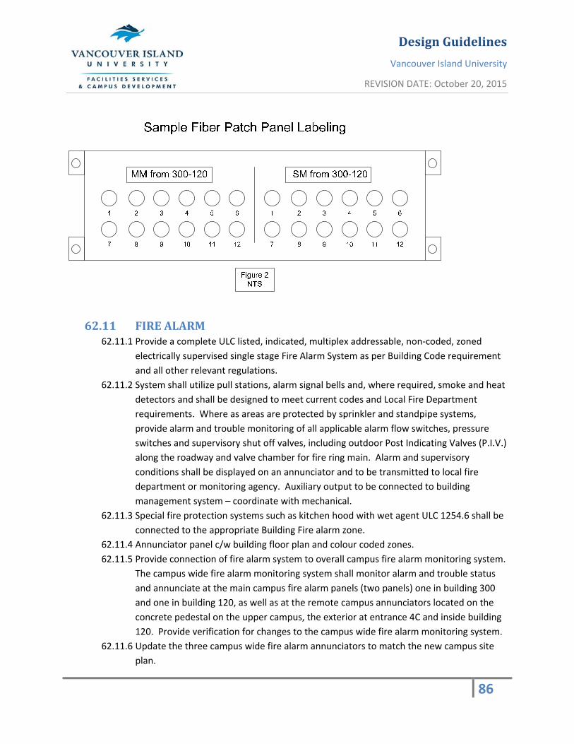
DesignGuidelines
Vancouver Island University
REVISION DATE: October 20, 2015
86
62.11 FIREALARM62.11.1 Provide a complete ULC listed, indicated, multiplex addressable, non‐coded, zoned
electrically supervised single stage Fire Alarm System as per Building Code requirement
and all other relevant regulations.
62.11.2 System shall utilize pull stations, alarm signal bells and, where required, smoke and heat
detectors and shall be designed to meet current codes and Local Fire Department
requirements. Where as areas are protected by sprinkler and standpipe systems,
provide alarm and trouble monitoring of all applicable alarm flow switches, pressure
switches and supervisory shut off valves, including outdoor Post Indicating Valves (P.I.V.)
along the roadway and valve chamber for fire ring main. Alarm and supervisory
conditions shall be displayed on an annunciator and to be transmitted to local fire
department or monitoring agency. Auxiliary output to be connected to building
management system – coordinate with mechanical.
62.11.3 Special fire protection systems such as kitchen hood with wet agent ULC 1254.6 shall be
connected to the appropriate Building Fire alarm zone.
62.11.4 Annunciator panel c/w building floor plan and colour coded zones.
62.11.5 Provide connection of fire alarm system to overall campus fire alarm monitoring system.
The campus wide fire alarm monitoring system shall monitor alarm and trouble status
and annunciate at the main campus fire alarm panels (two panels) one in building 300
and one in building 120, as well as at the remote campus annunciators located on the
concrete pedestal on the upper campus, the exterior at entrance 4C and inside building
120. Provide verification for changes to the campus wide fire alarm monitoring system.
62.11.6 Update the three campus wide fire alarm annunciators to match the new campus site
plan.

DesignGuidelines
Vancouver Island University
REVISION DATE: October 20, 2015
87

DesignGuidelines
Vancouver Island University
REVISION DATE: October 20, 2015
88
64 Mechanical
64.1 GENERALMECHANICALPROVISIONS
64.1.1 SCOPE64.1.1.1 All mechanical systems must be designed and constructed using proven
technology regarding maintaining durable and effective building envelope
assemblies, energy efficiency, occupant comfort, maintainability and operation
cost. In general, the approach should be to use proven available state‐of‐the‐art
mechanical systems.
64.1.1.2 Provide complete, fully tested and operational mechanical systems to meet the
requirements described herein and in complete accordance with applicable
codes and ordinances. The mechanical systems shall meet the performance
guidelines of the following specification. Pay for and obtain all permits,
authorizations and inspections required by the latest codes, laws and by‐laws
for mechanical systems.
64.1.1.3 The work specified in this section shall include but not necessarily be limited to:
64.1.1.4 Complete HVAC system supply and installation.
64.1.1.5 Complete plumbing and drainage supply and installation
64.1.1.6 Complete gas piping supply and installation.
64.1.1.7 Complete fire protection supply and installation.
64.1.1.8 Pipes and ductwork shall be installed in such a way as to conserve head room
and interfere as little as possible with the free use of space through which they
pass. Service lines shall run parallel to building lines. All duct and pipes at ceiling
shall be kept as tight as possible to beams or other limiting members at high
end. All pipes and ducts shall be coordinated in elevation to ensure that they are
concealed in the ceiling space provided. And as required by code.
64.1.1.9 Provide seismic restraints for all equipment, piping and ductwork where
required by code.
64.1.2 ENGINEERING64.1.2.1 Provide the following services and submittals for review by Vancouver Island
University:
64.1.2.2 At the time of completion of Design Development (25% complete design):
64.1.2.3 Submit drawings for input and review by the Owner and for coordination with
other trades and the Coordinating Professional.
64.1.2.4 At the time of Completion of Design:
64.1.2.5 Mechanical drawings and specifications suitable for construction issue.

DesignGuidelines
Vancouver Island University
REVISION DATE: October 20, 2015
89
64.1.3 EQUIPMENTSCHEDULES 64.1.3.1 Letters of Assurance, Schedules B1, B2 for all mechanical systems;
64.1.3.2 During Construction Phase and prior to ordering any equipment submit to the
Mechanical Engineer for review:
64.1.3.3 Shop Drawings of all equipment.
64.1.3.4 At the time of Substantial Completion:
64.1.3.5 Letter of Assurance, Schedule C‐B;
64.1.3.6 As‐built drawings of the mechanical systems;
64.1.3.7 Operation and Maintenance Manual.
64.1.3.8 Provide fixture catalog cuts
64.2 MATERIALS64.2.1 Materials and equipment installed shall be new, full weight and of performance and
approved manufacturers specified. Use same brand or manufacturer for each specified
application.
64.2.2 Each major component of equipment shall bear manufacturer's name, address, catalog
and serial number and equipment rating.
64.3 SHOPDRAWINGS64.3.1 Provide shop drawings as indicated in accordance with the MCA‐BC standards for shop
drawings.
64.3.2 Identify materials and equipment by manufacturer trade name and model number.
Include copies of applicable brochure or catalog material.
64.3.3 Clearly mark submittal material using arrows, underlining or circling to show differences
from specified, e.g. Ratings, capabilities and options being proposed. Cross out non‐
applicable material. Specifically note on the submittal specified features such as special
tank linings, pumps, seals, material, or painting.
64.3.4 Include dimensional and technical data sufficient to check if equipment meets
requirements. Include wiring, piping, and service connection data and motor sizes.
64.3.5 Shop drawings shall be endorsed by the General Contractor and Mechanical Sub‐
contractor indicating that the shop drawings have been reviewed and submitted
without qualifications.
64.3.6 Submit a minimum of (4) copies of shop drawings prior to ordering equipment.
64.3.7 Submit weights of all major equipment for review.
64.4 STANDARDSOFMATERIALS,EQUIPMENTANDINSTALLATION64.4.1 Provide equipment from approved manufacturers. All mechanical equipment shall have
the approved manufacturers name permanently affixed to it. Alternates to approved

DesignGuidelines
Vancouver Island University
REVISION DATE: October 20, 2015
90
manufacturers will be considered on review and approval by Vancouver Island
University.
64.4.2 Alternatives to the approved manufacturers list must be equal in quality and
performance to the approved manufacturers. Equipment that is not equal will be
replaced with the specified equipment at no cost to Vancouver Island University.
Submit sufficient information to Vancouver Island University to allow review for
approval of alternate manufacturers.
64.4.3 The equipment manufacturer shall ensure that the strength and anchorage of the
internal components of the equipment exceeds the force level used to restrain and
anchor the unit itself to the supporting structure.
64.4.4 Approved manufacturers are as follows:
Item Approved Manufactures / Suppliers
Access Doors Acudor, E.H. Price, Maxam, Steel Brothers, Milcor
Actuator Motors Belimo
Backflow Protection Watts, Febco, Clayton, Beeco, Wilkins,
Conbraco
Boilers (Natural Draft) Burnham, Bryan, Cleaver‐Brooks, Unilux
Veissman
Controls (DDC) Johnson Controls, Intelligent Building
Controls, Reliable Controls
Domestic Hot Water Heater John Wood, Elco, State, A.O. Smith,
P.V.I., Ruud
Duct Spiral And Fittings United Sheet Metal, B.C. Ventilating, Spiro‐Lok
Fans – Ceiling Mounted Greenheck, Broan, Nutone
Fans ‐ Roof Mounted Exhaust Cook, Greenheck, Acme, Carnes, Penn, Twin City Ventco
Filters Farr, Continental, Cambridge, AAF, Filtration GRP
Fire Dampers Canadian Advanced Air, Maxam, Ruskin, Controlled Air,
Nailor‐Hart
DesignGuidelines
Vancouver Island University
REVISION DATE: October 20, 2015
91
Fire Protection ‐ Sprinklers Grinnell, Viking, Star, Reliable
Flexible Air Duct Thermoflex, Wiremold, Flexmaster
Flush Valves Zurn 6000AV‐WS1/YO (Watercloset)
Zurn 6003 AV‐WS1
Air Handling units/ Engineered Air, Haakon
Gas Fire Make‐up Air/
Ventilation Units
Packaged Rooftop
Grilles, Diffusers and Registers E.H. Price, Krueger, Titus, Metalaire, Tuttle & Bailey, CARNES
Insulation ‐ Duct/Piping Fiberglas, Knauf, Johns‐Manville, Atlas, Ppg, Manson,
Armstrong, Armaflex
Jacketing Material Childers, Fiberglas, Johns‐Manville
Louvers Airolite, Penn, Westvent, Alumavent, Ruskin
Plumbing Drainage Accessories Smith, Zurn, Ancon
Plumbing Trim American Standard, Crane, Cambridge, Kohler, Eljer, Alsons,
Bradley, Powers, Symmons, Moen, Delta, Brasscraft, T & S
Brass, Emco, Gerber.
Plumbing Fixtures Crane, K.I.L., Fiat, Kohler, Eljer,
American, Moen
(All To Be Csa Approved) Standard, Aristanewman, Hytec
Pumps ‐ In‐Line Bell & Gossett, Aurora, Armstrong, Paco, Plad, Grundfos. TACO
Roof Top Air Conditioning Units Lennox, Carrier, Trane, McQUAY,
Engineered Air
Sound Attenuation I.A.C., Vibron, Vibro Acoustics

DesignGuidelines
Vancouver Island University
REVISION DATE: October 20, 2015
92
Balancing (Air and Water systems) Scott Technical, Flotech, Honey's Technical, Western
Mechanical, K.D. Engineering, BC Tech Engineering
Toilet Seats Beneke, Bemis, Olsonite, Moldex,
Sperze
Valves – Ball Red & White, Grinnell, Watts, Hills Mccanna
Valves ‐ Gate & Globe Red & White, Crane, Jenkins, Grinnell, Kitz
Valves ‐ Butterfly Centerline, Keystone, Grinnell
Valves ‐ Balancing/Flow Meter Tour / Anderson, Bell & Gossett,Armstrong
Vibration Control Equipment Vibro‐Acoustics, Lo‐Rez, Vibron, Korfund, Mason
Water Pressure Reducing Valves Wilkins, Slinger, Watts, Clayton, Bermad
64.5 PAINTINGANDIDENTIFICATION64.5.1 Clean all exposed bare metal surfaces supplied by the mechanical and plumbing trade
by removing all dirt, dust, grease and millscale.
64.5.2 Repaint all marred factory finished equipment, which is not scheduled to be repainted,
to match the original factory finish.
64.5.3 Natural gas and sprinkler piping shall be colour banded at 6’ intervals over their entire
lengths throughout all exposed areas and in the mechanical room as required by code
and as follows:
64.5.4 Gas: Yellow ‐ C.G.S.B. 505‐101
64.5.5 Fire protection (where exposed): Red 509‐102
64.5.6 Provide pipe markers and direction arrows ‐ in all exposed areas and in the mechanical
room:
64.5.7 Pipe marker letters are to be 50mm high for pipes 75mm and larger outside diameter
(including insulation) and not less than 18mm high for smaller diameters.
64.5.8 Location of pipe markers and direction arrows.
64.5.9 Pipe marker and direction arrow shall be placed side by side in the bottom quarter of
the pipe to be identified.
64.5.10 Adjacent to all major changes in direction and at connections to each piece of
equipment.

DesignGuidelines
Vancouver Island University
REVISION DATE: October 20, 2015
93
64.5.11 At least once in each room that the pipe passes through.
64.5.12 Where piping passes through walls, partitions, or floors, identify piping on both sides of
the section and at entry and exits to shafts.
64.5.13 Ceiling access panel identification the location of terminal units, valves, etc. Above
ceiling panels shall have their location identified by means of a colored tack or data dot.
64.6 TEMPORARYHEATING64.6.1 Do not use the permanent system for temporary heating or other purposes without
written permission from Vancouver Island University.
64.6.2 All equipment used shall be returned to new condition and warranties extended.
64.7 EQUIPMENTPROTECTIONANDCLEAN‐UP64.7.1 Protect equipment and material in storage on site and after installation until final
acceptance. Leave factory covers in place. Take special precautions to prevent entry of
foreign material into working parts of piping and duct systems.
64.7.2 Thoroughly clean piping, ducts and equipment of dirt, cuttings, and other foreign
material.
64.7.3 Protect bearings and shafts during installation. Grease shafts and sheaves to prevent
corrosion. Supply and install necessary extended nipples for lubrication purposes.
Install for easy access by maintenance away from moving parts.
64.8 SITEUTILITYSERVICES64.8.1 Co‐ordinate and maintain liaison with Vancouver Island University to interrupt, re‐route
or connect to water, sewer, storm, heating or gas systems, with minimum interruption
of service. Contact respective utility companies prior to starting work. Provide minimum
of 72 hours notice. No disruption to campus operations during normal campus hours.
64.8.2 Designer is to confirm outgoing storm and sewer line sizes and connection points so as
to meet the flow requirements of the new building.
64.8.3 Install anti‐rodent measures to both ends of all utility service duct banks – consult with
Vancouver Island University for detail.
64.9 ELECTRICALMOTORS64.9.1 Provide motors to CEMA and C.S.A. standards for hard, continuous service, designed to
limit temperature rise to 40C for open housing and 50C for drip proof housing, and
operate 1200 or 1800 R.P.M. unless otherwise specified. Do not use air over ratings.
64.9.2 Motors shall have ball or roller type bearings with grease lubrication fittings.
64.9.3 All belt‐driven devices shall have the motors mounted on adjustable bases with
adjusting screws so that proper belt tension can be obtained.

DesignGuidelines
Vancouver Island University
REVISION DATE: October 20, 2015
94
64.9.4 Where equipment has been specified to be complete with starters, disconnects and/or
control panels, this contractor shall provide any required wiring and conduit between
the equipment and the above items.
64.9.5 Motors of 15 kW and greater shall have capacitor and thermistor over heat protection.
Motor noise criteria shall not exceed NC‐60.
64.10 ACCESSDOORSANDPANELS64.10.1 Provide access panels required in building construction including in architectural walls
and ceilings for access to any concealed mechanical equipment which, in Vancouver
Island University's opinion, requires maintenance or adjustment. Access panel shall
match wall/ceiling finish.
64.10.2 Such panels shall be manufactured panels, with fastening devices, appropriate to the
construction involved, provide access panel for hand access,18"x 18" min. In wall /
ceiling to all mechanical system (such as valve, damper) requiring access. Dry wall
surface: Milcor style DW flush panel access door; masonry tile surface: Milcor style M;
plastered wall: Milcor style K.
64.11 ACCESSOFEQUIPMENT64.11.1 Make all arrangements to ensure that adequate access is available for all mechanical
equipment. Do all hoisting and rigging into place of all specified equipment and be
responsible for any damages incurred there from.
64.11.2 Contractor is to demonstrate reasonable access to all equipment service locations, if
found otherwise, remediation will be at contractors expense.
64.12 LIABILITY64.12.1 Assume full responsibility for laying out the work and for any damage caused to
Vancouver Island University by improper location, or carrying out of the work.
64.12.1.1 Examine and be responsible for the site and the local conditions affecting the work.
64.12.2 Arrange work in co‐operation with other trades in the building in such a manner as not
to interfere with other work being carried on in the building and places where other
pipes and equipment be installed along with the pipes and ducts pertaining to this
trade. Co‐operate with the other trades to get all the pipes, ducts, conduit, etc.,
Installed to the best advantage. When open web structural joists are used, must obtain
structural shop drawings to ensure space available for installation of pipes and
ductwork.
64.12.3 Where any pipes, ducts and equipment must be built into the work of other trades such
as masonry, structural, or plastering, be responsible for supplying the equipment to be
built in or measurements to allow the necessary openings to be left. All pipes and ducts
which are to be concealed shall be installed neatly and closely to the building structure

DesignGuidelines
Vancouver Island University
REVISION DATE: October 20, 2015
95
so that the necessary furring can be kept as small as possible. Any pipes, ducts, or other
work which are not, in the opinion of Vancouver Island University, installed as they
should be, shall be taken out and replaced without cost to Vancouver Island University.
64.12.4 Protect finished and unfinished work from damage due to the carrying out of this work,
giving special attention to the protection of building vapor barriers, waterproof
membranes, etc. Cover floors and other parts of the building with tarpaulins, etc., and
repair all damage to the satisfaction of Vancouver Island University. During freezing
weather, protect all his materials in such a manner that no harm can be done to the
installation already made and/or to materials and equipment on the job.
64.12.5 Be responsible for the condition of all materials and equipment supplied and shall
provide all necessary protection for same.
64.12.6 Be responsible for the protection and maintenance of the work of this section until the
building has been completed and accepted by Vancouver Island University.
64.12.7 On completion of the work, all tools and surplus and waste materials shall be removed
and the work left in a clean and tidy condition.
64.13 GUARANTEEWARRANTY64.13.1 Furnish a written warranty stating that all work executed under this division will be free
from defects of material and workmanship for a period of two (2) years from the date of
substantial performance, which shall include one (2) complete summer and one (2)
complete winter of uninterrupted operation. Warranty shall include any part of
equipment, units or structures furnished hereunder that show defects in the works
under normal operating conditions and/or for the purpose of which they were intended.
64.13.2 The contractor shall at his own expense promptly investigate any mechanical or control
malfunction, and repair or replace all such defective work, and all other damages
thereby which becomes defective during the time of the guaranty‐warranty.
64.14 PIPECHASESANDDUCTSHAFTS64.14.1 Unless otherwise indicated, conceal piping and ductwork in the construction of the walls
and ceilings, and in pipe chases, duct shafts and furring. If it is necessary, move the
location of pipes and ducts from those indicated and provided.
64.14.2 Minimize number of chases and shafts and locate in areas less likely to be affected by
future renovations.
64.14.3 Roof drain lines within the building are to be carefully reviewed to ensure that their
locations are in walls that are not likely to be renovated/removed/relocated.
64.15 INSPECTION64.15.1 Vancouver Island University may choose to inspect all work prior to it being concealed.
DesignGuidelines
Vancouver Island University
REVISION DATE: October 20, 2015
96
64.15.2 The contractor shall notify Vancouver Island University in writing for the following
minimum, but not limited to, inspections: (Required to provide a Schedule 'C' for
occupancy)
64.15.3 Below grade piping prior to backfill.
64.15.4 All HVAC and plumbing rough‐in prior to wall and ceiling finish installation.
64.15.5 Fire stopping of all openings.
64.15.6 Drop test all fire dampers and demonstrate access.
64.15.7 Trip test the fire protection system.
64.15.8 Pre‐occupancy inspection.
64.15.9 Final occupancy inspection and verification of all equipment being fully operational.
64.15.10 All work shall be approved by any other regulatory body having jurisdiction where
required.
64.15.11 The contractor is to provide copies of all permits, inspection reports and
certificates for insertion into the maintenance manual.
64.15.12 The contractor is to provide Vancouver Island University reasonable notice prior to
calling an inspection.
64.16 SUBSTANTIALPERFORMANCEINSPECTION64.16.1 Prior to the contractor requesting an inspection for substantial performance all the
following items must be provided to permit beneficial use by Vancouver Island
University:
64.16.2 Maintenance and operating manuals to be submitted.
64.16.3 As‐built drawings submitted.
64.16.4 Balancing reports (air and water.)
64.16.5 All systems shall be certified in writing by the contractor as complete and fully
operational.
64.16.6 Instructions to Vancouver Island University operating personnel shall be provided in
accordance with the specifications.
64.16.7 A complete list of items which the contractor has not finished, or are deficient shall be
provided. If, in the opinion of Vancouver Island University, this list indicates the project
is excessively incomplete, a substantial completion inspection will not be performed.
64.16.8 The contractor shall be fully responsible to accumulate all necessary data from his sub‐
trades and suppliers and present same in the specified format for the approval by
Vancouver Island University.
64.16.9 All life/safety items such as sprinkler systems, fire stopping, fire dampers, plumbing and
ventilation fixtures and ventilation must be operational.

DesignGuidelines
Vancouver Island University
REVISION DATE: October 20, 2015
97
64.17 LAWS,NOTICES,PERMITSANDFEES64.17.1 Give all necessary notices, obtain all necessary permits and pay all fees in order that the
work specified may be carried out, and furnish any certificates necessary as evidence
that the work installed conforms with the law and regulations of all authorities having
jurisdiction.
64.17.2 All work shall be in accordance with the regulations of the following authoritative
bodies, the codes in effect at the time of tender, and any others having jurisdiction:
64.17.2.1 Canadian Electrical Code AND BC ELECTRICAL INSPECTION BRANCH
64.17.2.2 1998 B.C. Building code
64.17.2.3 Worker's Compensation Board Standards
64.17.2.4 Canadian Standards Association
64.17.2.5 C.S.A. codes governing refrigeration plants
64.17.2.6 B.C. Gas Inspection Branch
64.17.2.7 B.C. Boiler Inspection Branch
64.17.2.8 Canadian Gas Code B‐149.1‐00
64.17.2.9 National Building Code of Canada
64.17.2.10 National Fire Protection Association
64.18 DEMONSTRATIONANDINSTRUCTIONTOVANCOUVERISLANDUNIVERSITYANDVANCOUVERISLANDUNIVERSITYREPRESENTATIVES64.18.1 Demonstrate to and instruct the representative designated by Vancouver Island
University on the complete mechanical systems operating and maintenance procedures
using the assistance of specialist sub‐trades and manufacturer’s representatives.
64.18.2 The following systems shall be demonstrated in regards to performance and safety
features (to the fullest):
64.18.3 Heating, ventilation, and air conditioning systems
64.18.4 Exhaust systems
64.18.5 Controls system
64.18.6 Plumbing Systems
64.18.7 Fire protection systems
64.18.8 Obtain a signed statement from a Vancouver Island University representative certifying
that the demonstration and instructions have been given to his satisfaction.
64.18.9 These requirements are in addition to those stated Operating and Maintenance Data
Section.
64.19 TESTING64.19.1 Perform all testing required by the authority having jurisdiction.
64.19.2 Obtain test certificates for all tests performed and include in operating manuals.
64.19.3 Perform the following tests: (where applicable)

DesignGuidelines
Vancouver Island University
REVISION DATE: October 20, 2015
98
64.19.4 Sanitary & storm hydraulic test.
64.19.5 Gas piping leakage test as per CSA Gas CODE
64.19.6 Sprinkler system tested to NFPA standards.
64.19.7 Domestic water test to 1 1/2 times max water pressure or (200psi).
64.19.8 Ductwork ‐ test medium velocity systems to a static pressure of system + 2" of W.G.
64.19.9 Drop test all fire dampers.
64.19.10 All tests specified by equipment suppliers and manufacturers to demonstrate
the equipment has been correctly installed.
64.19.11 All test shall be documented and witnessed by the Contractor Mechanical
Engineer or the general contractor or the owner’s representative.
64.20 BALANCING64.20.1 Contractor is to provide the services of an approved professional testing & balancing
firm.
64.20.2 Provide a balance report of all air & water balance points and performance testing &
balancing of all equipment as per the AABC.
64.20.3 Balance all air and water quantities to ‐ 5% or + 10% of the design requirement.
64.20.4 Provide all required sheave, belt and impeller changes to achieve the required fan and
pump flow rates. Changes to be updated in as built documentation
64.20.5 Measure and balance the following (where applicable):
64.20.6 Supply, exhaust and return fan volumes and speeds from all equipment.
64.20.7 Airflow at each air outlet and branch connection.
64.20.8 Adjust pattern control on supply diffusers.
64.20.9 Motor amperage draw on all motors and compare with motor rating.
64.20.10 Water at each balance valve and terminal heating or cooling unit.
64.20.11 An independent commissions agent will be engaged to oversee the balancing and
commissioning of the building systems. Consult with Vancouver Island University prior
to selection.

DesignGuidelines
Vancouver Island University
REVISION DATE: October 20, 2015
99
64.21 PIPE&PIPEFITTINGS64.21.1 Ensure all pipe materials and fittings are acceptable to the authority having jurisdiction.
64.21.2 All type 'K' copper must be certified to ASTM B88. Provide written guarantee that lead
free solder was used on all domestic water systems.
64.21.3 Approved pipe & fittings: (Non‐combustible construction)
Service Pipe Fittings
(a) Sanitary above grade DWV copper Wrought Copper or cast brass 95‐5
solder cast iron gasket with stainless steel coupling
(b) Sanitary below grade cast iron gasket with stainless steel coupling
ABS Solvent joint
P.V.C./D.W.V. Solvent joint
(c) Storm drainage above cast iron gasket with stainless steel coupling
copper copper or brass with 95‐5 solder
(d) Storm drainage below cast iron gasket with stainless steel coupling
ABS Solvent joint
P.V.C./D.W.V. Solvent joint
(e) Footing Drainage P.V.C. SDR#35 Solvent joint
(f) Domestic Water Above Type 'L' Hard Copper Wrought copper or brass with
95.5% solder (lead free)
(g) Domestic water buried P.V.C. Ringtight Grooved mechanical joints
Cement lined ductile
iron Grooved mechanical joints
Type 'K" & 'L'soft
Copper Wrought Copper or brass 95‐5
solder
(h) Fire protection To N.F.P.A. Standard Screwed or mechanical joints

DesignGuidelines
Vancouver Island University
REVISION DATE: October 20, 2015
100
64.21.4 Contractor to provide drains at all low points in the piping system.
64.21.5 Alternates to approved materials will be considered on review and approval by
Vancouver Island University.
64.22 SUPPORT,ANCHORS&SEALS64.22.1 Provide all necessary supports, and hangers to secure mechanical systems and
equipment.
64.22.2 Provide fire stopping at all duct and piping penetrations through rated floors/walls and
shafts.
64.22.3 Provide oversize hangers on all cold pipes to fit over pipe insulation where required.
64.22.4 Provide isolation and prevent contact with dissimilar metals.
64.22.5 All sleeves for mechanical piping to extend 1" above the floor in all mechanical room,
shaft and wet areas.
64.22.6 All ductwork to be supported as per SMACNA.
64.22.7 All exposed piping penetrations shall be provided with escutcheons.
64.23 VALVES
64.23.1 SCOPE64.23.1.1 Provide valves for domestic water, gas and refrigeration systems.
64.23.1.2 Provide gate, globe, ball, butterfly, drain and check valves.
64.23.1.3 Provide all necessary valves suitable for the fluid and piping system.
64.23.1.4 All valves must be suitable for a working pressure 1380 kPa at 121%.
64.23.1.5 Install all valves in upright or horizontal position.
64.23.1.6 Provide drain valves at all low points in the piping system.
64.23.1.7 Provide isolation valve at each plumbing fixture.
64.23.1.8 Valves permitted:
< 2" Diameter 2" Diameter >
Domestic Hot & Cold Gate, Ball Gate, Butterfly
Heating Water Gate, Ball Gate, Butterfly
64.23.1.9 Valves up to 2" diameter can be sweated or screwed connection. Valves larger
than 2" diameter must be screwed, flanged or mechanically coupled to piping
system.
64.24 VIBRATIONISOLATION
64.24.1 SCOPE64.24.1.1 Provide vibration isolation for all motor driven equipment. To maintain noise
criteria levels at or below ASHRAE recommended levels.

DesignGuidelines
Vancouver Island University
REVISION DATE: October 20, 2015
101
64.24.1.2 Provide spring isolator for all motor driven equipment larger than 1/2 H.P. For
equipment 1/2 H.P. and less Neoprene isolators may be used. Unless mounted
to a surface adjacent to full time occupied space then will be spring isolation,
regardless of motor size.
64.24.1.3 All isolators provided shall incorporate seismic restraints. Isolators for base
mounted equipment shall be seismic isolators.
64.24.1.4 Provide horizontal limit springs on all fans (except vertical discharge) in excess
of 0.3" static pressure.
64.24.1.5 All floor mounted non isolated equipment (ie. boilers, tanks, air handling units)
shall be bolted to structure and be designed for a 2g applied horizontal force.
64.24.1.6 Submit shop drawings of isolator, which are not supplied by the equipment
manufacturer.
64.24.1.7 All electrical connections to equipment to be provided with flexible connectors
and cable with a minimum 30o bend or flexible conduit.
64.24.1.8 Provide flexible ductwork and piping connections and duct vibration isolators to
all equipment which incorporates vibration isolations.
64.25 SEISMICREQUIREMENTS
64.25.1 SCOPE64.25.1.1 Seismic restraints for all equipment, ductwork, and piping. Attachment to
structural members.
64.25.1.2 Reference standards: Seismic requirements shall be in accordance with the
following:
64.25.1.3 1998 B.C. Building code section 4.1.9
64.25.1.4 N.F.P.A. 13
64.25.1.5 SMACNA "Guidelines for seismic restraints of mechanical systems and plumbing
piping systems".
64.25.1.6 Contractor to provide professional certification from specialist seismic items
trade prior to report for completion or occupancy inspection, whichever is the
earlier.
64.25.1.7 The installation of seismic restrains shall not compromise vibration isolation
capabilities.
64.26 INSULATION64.26.1 Installation shall conform to the B.C.I.C.A. Quality Standards Manual for mechanical
insulation.
64.26.2 Piping insulation
64.26.3 Provide vapour barrier for all cold pipes.

DesignGuidelines
Vancouver Island University
REVISION DATE: October 20, 2015
102
64.26.4 Rain water leaders to be insulated in all heated spaces.
64.26.5 All exposed piping to be complete with PF‐3 economy finish. No finish required on
concealed piping.
64.26.6 Provide insulation thickness and type as follows: (where applicable)
Service Size Insulation Type
Thickness
Domestic hot & cold up to 1"Ø ½ " Mineral fibre
Domestic hot & cold 1 1/2"Ø & up 1" Mineral fibre
H/C Plumbing Traps all ½ " Mineral fibre
(removable cap)
Storm R.W.L. all ½ " Mineral fibre
Condensate drain all ½ " Mineral fibre
64.26.7 Insulate all exposed traps under handicapped sinks with factory installation kit.
64.26.8 Insulate air conditioning unit condensate drain for the first (5'‐0")
64.26.9 Domestic water piping insulation on mains and piping in ceiling space. Drops down
walls to fixtures are not required to be insulated.
64.26.10 Provide heat tracing and weather proof jacketing for all piping insulation
exposed to the weather including hydronic heat pump and make‐up water connection
to fluid cooler.
64.26.11 DUCTWORKINSULATION64.26.11.1 Provide external ductwork insulation as per the following: (where applicable)
Service Thickness Type
Air conditioned supply 1" Mineral fibre thermal
Heating supply air duct 1" Mineral fibre thermal
Outside air intake 1" Mineral fibre thermal
Ductwork in unheated space 1" Mineral fibre thermal
64.26.11.2 All exposed ductwork in mechanical rooms to be rigid insulation with RF4
economy finish.
64.26.11.3 Provide vapour barrier in accordance with specification EF‐2
64.26.11.4 Exposed heating and air conditioned ductwork installed in an exposed area in
which it is serving, need not be insulated.
64.26.11.5 External insulation is not required where ductwork is internally lined.

DesignGuidelines
Vancouver Island University
REVISION DATE: October 20, 2015
103
64.26.11.6 Ductwork exposed to the weather shall be provided with weather proof
jacketing (P.V.C. or Aluminum).
64.26.11.7 Main discharge ductwork from air handling units are to be insulated. Branch
run outs to diffusers less than 20 feet and flexible connections are not required
to be insulated.
64.26.11.8 Make‐up air ventilation ductwork is not required to be insulated.
64.26.12 ACOUSTICINSULATION64.26.12.1 Provide 1" internal acoustic neoprene duct liner upstream and downstream a
minimum of 10'‐0" from all supply, return and exhaust fans ½ hp and larger.
64.26.12.2 Provide 1” internal acoustic neoprene lined return air elbow for all heat pumps
and provide a minimum of 10 feet and one elbow of 1” internal acoustic
neoprene lined ductwork on the discharge from all heat pumps.
64.26.12.3 All insulation edges must be sealed. Provide fasteners at 12" O.C. with pins cut
and capped.
65 PLUMBINGGENERAL
65.1.1 SCOPE 65.1.1.1 Review the architectural drawings for location and number of plumbing fixtures
to be provided in the building. All plumbing fixtures to be of commercial
quality, with flush valve type wall outlet water closets and urinals.
65.1.1.2 Provide roof drainage to new roof areas, including piping and connection to
existing storm system.
65.1.1.3 Provide footing drainage and sediment sump.
65.1.1.4 Provide domestic cold, hot, and hot water recirculation piping to new fixtures,
complete with piping insulation, isolation valves.
65.1.1.5 Provide hose bibbs at exterior of building at every side of the building. Exterior
hose bibbs shall be non‐freeze type with vacuum breaker and lockable wall box.
65.1.1.6 Provide a DHW and DCW hose bib at a central location on each roof level.
65.1.1.7 Comply with BC Plumbing Code Current Version.
65.1.1.8 Supply and install cleanouts on all drains, changes in direction, at base of riser
and on main sanitary and storm leaving building in addition to the B.C. Plumbing
Code.
65.1.1.9 Supply solenoid valve, connected to DDC, to any trap primer water supply.
65.1.1.10 Where drains are located over an occupied area, membrane clamp is to be
provided with drain for a waterproof installation.
65.1.2 Prior to commencing the underground plumbing installation, excavate and verify:
65.1.2.1 The location, elevation and size of storm and sanitary service connections.

DesignGuidelines
Vancouver Island University
REVISION DATE: October 20, 2015
104
65.1.2.2 The sanitary and storm lines can be routed and sufficiently sloped with
adequate cover for freezing protection to meet the service connections.
65.1.2.3 Inform the engineer immediately if any changes are required.
65.1.3 All floor drains shall have trap primer connection.
65.1.4 Lead free solder to be used for all potable water systems. Contractor to issue guarantee
of such in maintenance manual.
65.1.5 Provide unions to all equipment and valved connections for 2‐1/2" and below. Flanged
connections for 3" and over.
65.1.6 Provide necessary thrust block, anchor, etc. to underground water piping at all change
of direction, all tees and at the end of all mains and branches.
65.1.7 Provide any excavations necessary for the installation of the mechanical work. No
cutting, boring or excavating necessary for this work in or about the building which may
cause interference with the progress of the work or weaken the structure in any way,
shall be undertaken. Trenches for all underground piping shall be excavated to a depth
slightly more than required and graded so as to secure all available fall. Support each
length of pipe with concrete blocks and bricks, or backfill the trench with gravel to the
required depth and grade. Sanitary and storm lines outside of the building shall be kept
as deep as practical.
65.1.8 Backfilling in all trenches shall be with sand or pea gravel where approved, 150mm
below pipe and up to 150mm over top of piping.
65.1.9 Where sewer, water or storm pipes pass through exterior walls below grade, shall install
corbels on the exterior walls and run bridging for corbel to undisturbed soil for the
support of the pipes. One inch thick waterproof mastic shall be applied around the pipes
which pass through the wall.
65.1.10 Provide chrome escutcheon plate for all plumbing rough‐in. (metal only)
65.1.11 Gas piping shall comply with National Standard of Canada CAN1‐B149.1‐00 and the BC
Gas Safety Branch Bulletins. Installation code of natural gas burning appliances and
equipment. Provide necessary pressure regulator to suit. Prime coat and paint lines
exposed to outdoor.
65.1.12 Provide Seismic valve to main gas feed. Re & Re existing gas utility piping to
accommodate new building requirements.
65.1.13 Provide lead sheet flashing and sheet metal counter flashing for pipe passing through
roof deck structure.
65.1.14 Provide non‐conducting type connection for joining or supporting. Provide separation
between dissimilar metals.
65.1.15 Provide stop valve to all equipment and plumbing fixture connection. Provide stop valve
to base of water risers. Provide isolation valves for all fixture trim unless complete with
integral stops.

DesignGuidelines
Vancouver Island University
REVISION DATE: October 20, 2015
105
65.2 PLUMBINGFIXTURES&TRIM65.2.1 Provide commercial quality drains and plumbing fixtures throughout the building.
Provide low water consumption fixtures. Shop drawings and list of proposed plumbing
fixtures to be submitted for review by Vancouver Island University. Refer to the list of
approved manufactures.
65.2.2 Plumbing fixtures of the same usage and type must be of the same manufacturer. i.e.
all water closets to be of the same manufacture and all sinks to be of the same
manufacturer.
65.2.3 All plumbing fixtures to be CSA approved and meet the requirements of the BC building
code for handicapped accessibility where required.
65.3 CLEANING&CHEMICALTREATMENT65.3.1 Provide for cleaning and disinfection of all domestic hot & cold water systems.
65.3.2 During system flushing ensure that all control valves and other system valves are in the
full open position.
65.3.3 All domestic water piping shall be thoroughly flushed so that it is free from all scale,
sediment etc.
65.4 FIREPROTECTION65.4.1 Provide complete sprinkler system complying with NFPA No. 13 1996, and local
municipal by‐laws and requirements. In addition, to comply with Vancouver Island
University’s insurance authority requirements. all material shall be listed by ULC or
approved for sprinkler use. Pipe sizing by hydraulic calculations.
65.4.2 The Sprinkler Contractor is to include in his tender the cost of providing hydraulically
calculated, engineered fire protection system.
65.4.3 The engineer shall obtain relevant water flow and pressure characteristics from the
Owner for use in his design.
65.4.4 The engineer shall provide all professional letters of assurance (from the British
Columbia Building Code) that may be required by the local Building Inspector, and
provide site reviews of the installation sufficient to satisfy requirements of such
submissions.
65.4.5 Contractor is responsible for obtaining water supply information and preparing
hydraulic calculations accordingly. Allow 10% safety margin (or a minimum of 10 psi) on
pressure at base of risers. Contractor to confirm incoming water line size required by
hydraulic calculation before water connection application and installation of any on site
plumbing.

DesignGuidelines
Vancouver Island University
REVISION DATE: October 20, 2015
106
65.4.6 Contractor to perform testing in presence of Vancouver Island University and submit
NFPA Testing contractor's Certificate.
65.4.7 Provide spare sprinkler heads for system (less than 300 heads, provide 6 and up to 1000
heads provide 12), and turn over to Vancouver Island University at the end of
construction.
65.4.8 Run all piping concealed. Piping subject to freezing to be insulated and heat traced.
65.4.9 Design standards:
General floor areas N.F.P.A.‐13, light hazard, wet system.
Mechanical & service rooms NFPA – 13 ordinary hazard, wet system.
65.4.10 Supply & install following for Fire alarm/trouble supervision:
Valve movement supervisory switch for all moveable valves
Low water pressure switch.
Alarm flow switches for each level of the building
All else as required by code
65.4.11 Coordinate sprinkler head locations with the reflected ceiling plan and center heads on
the ceiling tiles. Coordinate sprinkler head locations with other ceiling mounted devises
such as lights and diffusers.
65.5 METERING65.5.1 Provide digital water metering of the main water supply to the building or major zones
of the building. Confirm type of meter with VIU.
66 HVACSYSTEMS
66.1.1 SCOPE66.1.1.1 The building HVAC system will consist of:
66.1.1.2 Natural gas fired packaged rooftop AC units with DDC controlled outside air
dampers with Belimo actuator motors – factory enthalpy and economizer
controls not required;
66.1.1.3 Heating and cooling cycles to be controlled by DDC;
66.1.1.4 Rooftop units to be configured/zoned to accommodate optimum zone control
for the different room functions/space utilization and orientation i.e. increased
heating load of computer labs, solar exposure, regular instruction space,
administration, general purpose rooms, etc.;
66.1.1.5 Proposed design to be reviewed with Vancouver Island University ;
66.1.1.6 Washroom, storage and janitorial exhaust fans (door grills allowed for these
locations only);
66.1.1.7 Return air transfer boots & grills
66.1.1.8 NOT APPROVED
(a) Unit Ventilators
DesignGuidelines
Vancouver Island University
REVISION DATE: October 20, 2015
107
(b) Door grills for return air (except as noted above)
(c) Under cutting of doors for return of relief air
66.1.1.9 Design Conditions
(a) Outdoor design temperatures to be as per the 1998 B.C. Building
Code:
(b) Winter 1% outdoor design
(c) Summer 2.5 % outdoor design
66.1.1.10 Indoor design temperatures to be as per the following:
(a) General public usage & meeting rooms 23°C Cooling
(b) General public usage & meeting rooms 21°C Heating
(c) Washrooms & changerooms 21°C Heated
(d) Storage rooms 18°C Heated
(e) Service Rooms 30°C maximum
(f) All areas – night set back 16°C Heated
66.1.1.11 Ventilation requirements as per ASHRAE 62‐1989
66.1.1.12 Acoustic requirements as per ASHRAE standards:
66.1.1.13 Finished office space NC‐35
66.1.1.14 Meeting rooms and classrooms NC‐30
66.1.1.15 Storage rooms and washrooms NC‐40
66.1.1.16 All other spaces NC‐35
66.1.1.17 Provide washroom exhaust system ductwork and ceiling mounted grilles for all
public washrooms, to a minimum of 15 AC/HR or 2 CFM/ sq.ft.
66.1.1.18 Provide rooftop mechanical equipment, complete with roof curbs, seismic
restraints, equipment start‐up and balancing, electrical and natural gas supply.
Provide 120V utility outlet at each unit for maintenance purposes. Ensure
vibration and noise isolation. Mount rooftop units over corridors and storage
rooms wherever possible.
66.1.1.19 Provide one set of filters with each unit and a second set, to be installed at
substantial completion.
66.1.1.20 Provide approved fall arrest anchors on each rooftop unit that requires
maintenance access closer than 2 metres (6ft) from roof edge and where not
provided in the roofing specification.
66.1.1.21 Provide ducting distribution, ceiling diffusers to suit ceiling design, and direct
digital controls to meet desired operation.
66.1.1.22 Provide ventilation for electrical rooms, storage rooms, and elevator machine
room.
66.1.1.23 Provide all systems with energy saving considerations.

DesignGuidelines
Vancouver Island University
REVISION DATE: October 20, 2015
108
66.1.1.24 Submit a list of all proposed equipment, for review by a Vancouver Island
University representative.
66.1.1.25 Provide approved screening around rooftop units for aesthetic purposes –
screens not to reduce operating efficiencies of units
66.2 SHEETMETALDUCTWORK
66.2.1.1 Ductwork shall be galvanized steel, lock formed 2" W.G. SMACNA standard for
low velocity and medium velocity ductwork quality. Fabricated in accordance
with SMACNA duct manuals and ASHRAE handbooks. Ductwork shall meet the
requirements of NFPA 90A and 91 and conform to applicable codes.
66.2.1.2 Prior to fabrication of ductwork, check all ceiling spaces and heights and conflict
with other trades. Include and provide necessary offset to maintain ceiling
height, headroom etc.
66.2.1.3 Provide minimum 450mm x 450mm (18"x 18") access panels to manual
dampers, equipment, fire dampers.
66.2.1.4 All ductwork shall be delivered to site in a clean condition and remain clean.
During installation all open ends of ductwork shall be capped with sheet metal
or poly and kept clean.
66.2.1.5 Provide flexible duct connections from duct branches to supply air diffusers, 915
mm (3’.0”) Flexmaster “Fab‐4” or equivalent, maximum. Flex shall be thermally
insulated if supply ductwork is insulated.
66.2.1.6 All ducts associated with fans, and other vibration isolated equipment shall be
installed with flexible connections on the inlet and outlet openings.
66.2.1.7 All ductwork penetrating fire separations shall be complete with fire dampers.
66.2.1.8 Provide balancing dampers where indicated on drawings and at all duct
branches. Provide additional balance dampers at the request of the balancing
agent to facilitate balancing.
66.2.1.9 Paint all visible ductwork through supply, return or exhaust grilles to back
ground colour. Coordinate on site.
66.2.1.10 Size all ductwork to ASHRAE standards or 0.1 “/100 feet of static pressure and a
maximum of 1200 feet per minute velocity.
66.2.1.11 Provide seismic supports for grilles, diffusers, and ducts where duct length
exceeds 5X duct diameter (as per code).
66.2.1.12 Provide turning vanes for all rectangular elbows installed as per SMACNA.
66.2.1.13 Roof mounted ducts shall have standing seams and sealed water‐tight.
66.2.1.14 Provide back draft damper to all exhaust outlets at exterior.
66.2.1.15 Provide galvanized steel screen, 1/2" x 1/2" square mesh for exterior intake &
exhaust outlets.

DesignGuidelines
Vancouver Island University
REVISION DATE: October 20, 2015
109
66.2.1.16 Provide flashing, curb and counter flashing for all ducting passing through roof
and external envelope of the building.
66.3 FIREDAMPERS66.3.1 Provide U.L.C. Approved fire dampers made of galvanized steel or prime coated black
steel weighted to close and lock in closed position when released by fusible link.
66.3.2 Fire dampers in low‐pressure ductwork may be multi blade or curtain type.
66.3.3 Fabricate combination fire and balancing dampers with linkage readily adjustable in
open position.
66.3.4 Curtain fire dampers shall have blades retained in a recess so free area of connecting
ductwork is not reduced.
66.3.5 Fusible links shall be set for 72C. 66.3.6 The contractor shall drop test all fire dampers and provide a written report confirming
that all fire dampers have been tested and are operational.
67 BUILDINGAUTOMATIONSYSTEM67.1.1 Provide a Building Automation System (BAS) incorporating Direct Digital Control
(DDC), energy management, equipment monitoring and control consisting of the
following elements:
67.1.2 An extension of the campus METASYS or Reliable network of automated controls
installed by the following approved contractors:
67.1.3 Johnson Controls Ltd.
67.1.4 Intelligent Building Controls Ltd.
67.1.5 Houle Electric (Reliable System)
67.1.6 Microcomputer based remote stand‐alone controllers interfacing directly with sensors,
actuators and environmental delivery systems.
67.1.7 A two‐Wire communication network to allow data exchange between stand‐alone
controllers and between stand‐alone controllers, network control processors and the
central BAS computer. Existing Johnson Controls (N2) trunk cable between buildings
200 and 195 will be re‐routed to SOMC communications room or main DDC panel
location. Reliable System trunk will be new and fed in from building 120
67.1.8 All other computer hardware and software, modem interface, communication devices,
controllers and field sensors and electrical components necessary to meet the specified
performance.
67.1.9 Setting in place all field devices of valves, flow meters, water pressure and differential
taps and devices, flow switches, current switches, thermal wells, dampers, air flow
stations, and current transformers where required or necessary to complete a building
automated control system.

DesignGuidelines
Vancouver Island University
REVISION DATE: October 20, 2015
110
67.1.10 The installer must be a licensed representative, affiliate or operating division of the
controls manufacturer with a minimum of five (5) years experience installing BAS's. The
supplier shall have a compete support facility to provide a 24 hour a day, seven days a
week emergency repair service.
67.1.11 The system shall be installed by competent mechanics and technicians, regularly
employed by the BAS manufacturer with full responsibility for proper operation of the
BAS including debugging and proper calibration of each component in the entire system.
67.1.12 The Building Automation System shall incorporate Direct Digital Control (DDC) and
provide:
67.1.13 Colour display graphics to monitor and control all system parameters and setpoints.
Located on the campus central control computer.
67.1.14 Optimum start/stop and operational control sequences of HVAC equipment and
interfacing of all controls as specified.
67.1.15 Equipment fault, fire system fault, sump pump high level and operating setpoint alarms
where indicated.
67.1.16 Monitoring, scheduling and adjustment of operating setpoints as indicated (space
temperatures, DHW temperatures, heating water temperatures, space humidity levels,
supply air temperatures equipment operating status, CO2 etc.)
67.1.17 Modular in nature, the BAS shall be capable of expansion in both capacity and function
with the addition of DDC controllers and field devices.
67.1.18 Each DDC controller shall have a minimum of 20% spare capacity for future I/O point
connection in proportions to the specified functions. Provide a minimum of two spares
for each I/O type per controller and expansion cards.
67.1.19 Provide sufficient internal memory to perform the specified control sequences and an
additional 25% capacity for future use.
67.1.20 Monitoring and totalization of metering of electrical power (kW, kWh, pf), water
consumption, and natural gas.
67.1.21 Monitoring and control of all aspects of building lighting system, fire protection system,
security system and any other systems as designated.
67.1.22 The BAS controllers and system software shall include an operating system, data base
management, communications control, scheduling applications, stand‐alone equipment
control and incorporate:
67.1.23 Dynamic colour graphic representations and menu driven, window type functions with
complete mouse‐activated operation.
67.1.24 Equipment scheduling, totalization and optimization.
67.1.25 HVAC energy management routines to be reviewed with owner
67.1.26 Preprogrammed algorithms for typical HVAC control .
67.1.27 Trend and history files.
67.1.28 Printed and audible alarm processing.
DesignGuidelines
Vancouver Island University
REVISION DATE: October 20, 2015
111
67.1.29 Application and custom software to accomplish all sequence of operations of the
equipment.
67.1.30 Equipment maintenance and parts inventory program
67.1.31 Remote access with graphic capabilities via web browser
67.1.32 Network (Ethernet) connectivity – owner to supply IP address as required.
67.1.33 Add CO2 sensor to return air of ventilating unit.
67.1.34 The BAS will control the lighting (see section # in electrical specification for details).
67.1.35 The BAS will monitor a signal from the fire alarm panel to shutdown fan systems as
required in the event of a fire.