Embed Size (px)
Citation preview
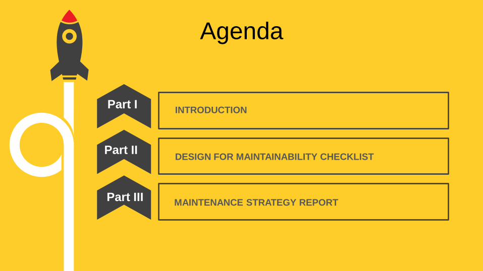
Agenda
INTRODUCTION Part I
DESIGN FOR MAINTAINABILITY CHECKLIST
MAINTENANCE STRATEGY REPORT
Part II
Part III

PART I - INTRODUCTION
1 2 3 4
Design for
Maintainability
Scope of
checklist
Purpose of
Checklist How to use
the checklist
Design for
Maintainability
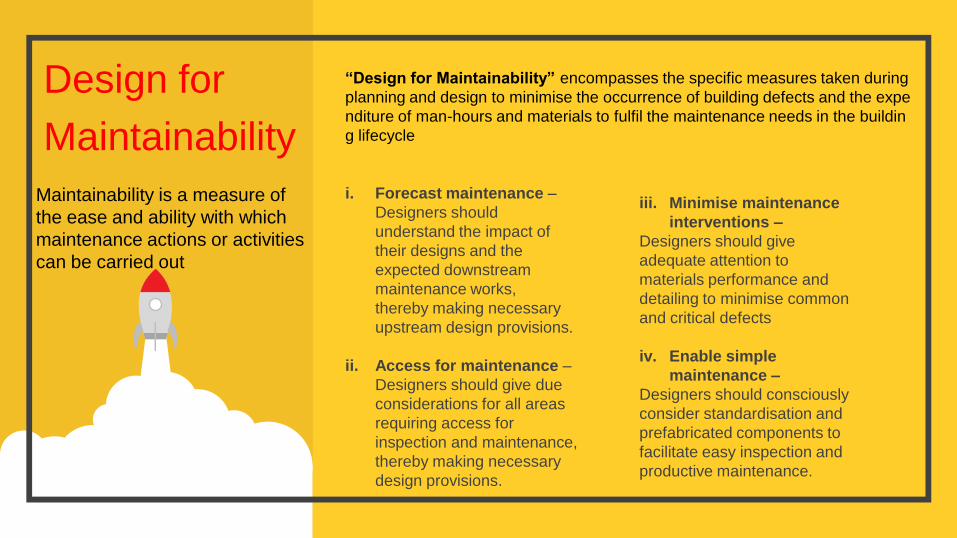
i. Forecast maintenance –
Designers should
understand the impact of
their designs and the
expected downstream
maintenance works,
thereby making necessary
upstream design provisions.
ii. Access for maintenance –
Designers should give due
considerations for all areas
requiring access for
inspection and maintenance,
thereby making necessary
design provisions.
iii. Minimise maintenance
interventions –
Designers should give
adequate attention to
materials performance and
detailing to minimise common
and critical defects
iv. Enable simple
maintenance –
Designers should consciously
consider standardisation and
prefabricated components to
facilitate easy inspection and
productive maintenance.
Maintainability is a measure of
the ease and ability with which
maintenance actions or activities
can be carried out
“Design for Maintainability” encompasses the specific measures taken during
planning and design to minimise the occurrence of building defects and the expe
nditure of man-hours and materials to fulfil the maintenance needs in the buildin
g lifecycle

Purpose of
Checklist
The intent of this document is to provide a set of design recommendations and
best practices to aid developers and architects in integrating and maintainability concepts in
the upstream design processes, thereby promoting quality design with consideration of
productivity, safety and labour efficiency in downstream building maintenance activities.
The checklist is expected to be a useful reference for architects, engineers, developers,
facilities and building managers, and service providers.
It should be noted that the checklist is not meant to be definitive nor exhaustive. The
generic nature of this checklist does not account for the variances in maintenance
objectives in different building types.
It also does not address construction quality, maintenance operations and the economic
aspects of design decisions. The checklist is not intended to override or replace any legal
rights, responsibilities or regulatory requirements.

Scope of Checklist The framework of the Design for Maintainability Checklist is structured according to the main components of a
building. Each building component is then considered in relation to three critical maintainability design factors.
a) Main Building
Areas
• Facades and External
Walls
• Roof Areas
• Common Areas, Lift
Lobbies and Corridors
• Parking Areas
• Other Building Areas
e.g. washrooms,
facilities for cleaners
c) Landscape and
Outdoor Areas
• Planting and Turf Roof
Areas
• Water Features
• Other Landscaped
Areas e.g. outdoor
furniture, footpaths
b) Mechanical and
Electrical (M&E)
Facilities
• Plant, Machinery and
Fixed Equipment roof
Areas
• Security
• Piping and Exposed
Services
The main building components identified are:-

The three critical maintainability design factors are: I. Access for Maintenance
• The ability and ease to access, inspect and maintain various parts of a building is a critical fact
or for enabling efficient routine servicing and maintenance works.
• Access provisions must be designed to be safe and provide sufficient circulation and working
space for maintenance vehicles or personnel carrying tools, equipment and component parts.
• Where possible, a building should be designed to remove the need for temporary or makeshift
access such as scaffolding and ladders.
Key considerations include:
• Adequate provision of access for execution of maintenance tasks including cleaning inspections, repair and
replacement of materials, components or equipment.
• Design layout gives sufficient circulation and working space, including headroom
• Minimise the need for maintenance at height or in confined spaces.
• Where it is not possible to eliminate the need for maintenance at height or in confined spaces, measures
should be put in place to reduce the risks associated with working at height or in confined spaces.

II. Materials and Finishes
• Beyond the aesthetics qualities, designers should consider the suitability of
materialis in terms of their ability to resist defects from normal wear and tear
(durability), and perform the intended functions throughout the design life.
• The appropriate use of materials can minimise the frequency of cleaning, repair and
replacement.
Key considerations include:
• Strike a balance between aesthetics, costs, safety and maintenance needs.
• Select materials that are durable and suitable for the local climate.
• Choose materials that are easily available during the life of the building.
• Consider innovative, high-performance materials that require minimal maintenance.

III. Design and Detailing
• Proper architectural design and construction detailing can help to minimise the
occurrence of defects and reduce the need for maintenance interventions.
• The main concerns include having careful detailing to prevent staining, water penetr
ation and premature deterioration, as well as to enable simple maintenance methods
and replacement of elements.
Key considerations include:
• Proper and effective detailing to reduce the impact of weather.
• Design enables simple maintenance methods, such as easy diagnostic checks,
installation and disassembly/assembly of components.
• Consider standardisation and modular layout of components.
• Consider prefabricated materials/ components.
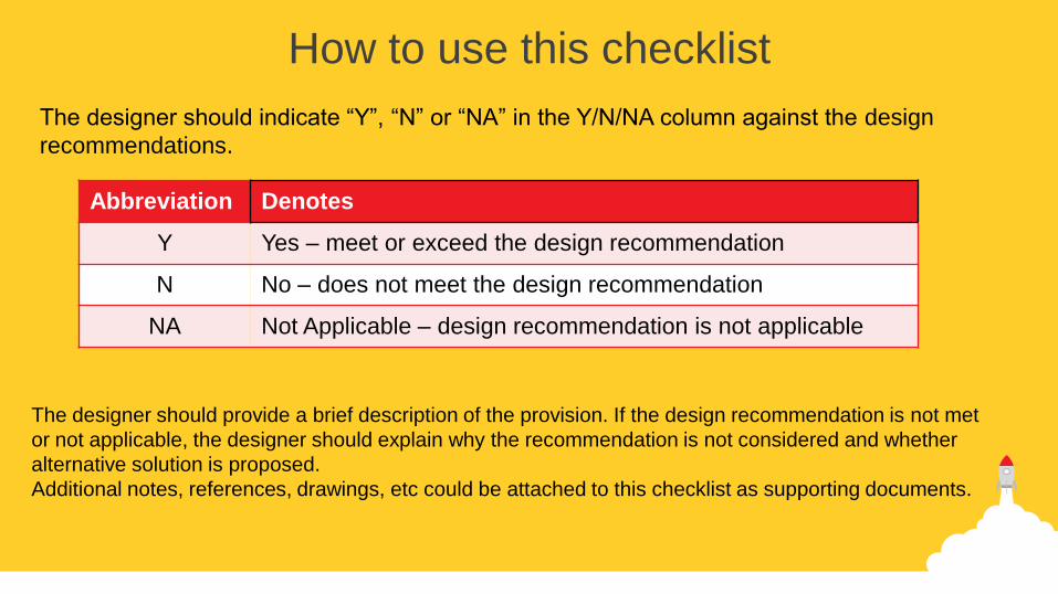
How to use this checklist
The designer should indicate “Y”, “N” or “NA” in the Y/N/NA column against the design
recommendations.
Abbreviation Denotes
Y Yes – meet or exceed the design recommendation
N No – does not meet the design recommendation
NA Not Applicable – design recommendation is not applicable
The designer should provide a brief description of the provision. If the design recommendation is not met
or not applicable, the designer should explain why the recommendation is not considered and whether
alternative solution is proposed.
Additional notes, references, drawings, etc could be attached to this checklist as supporting documents.
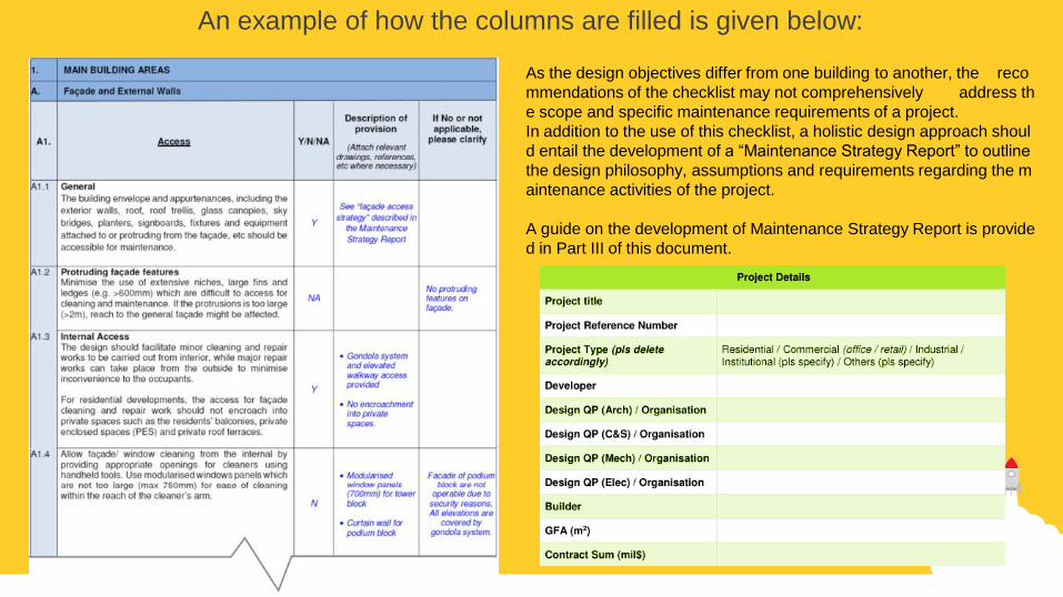
An example of how the columns are filled is given below:
As the design objectives differ from one building to another, the reco
mmendations of the checklist may not comprehensively address th
e scope and specific maintenance requirements of a project.
In addition to the use of this checklist, a holistic design approach shoul
d entail the development of a “Maintenance Strategy Report” to outline
the design philosophy, assumptions and requirements regarding the m
aintenance activities of the project.
A guide on the development of Maintenance Strategy Report is provide
d in Part III of this document.
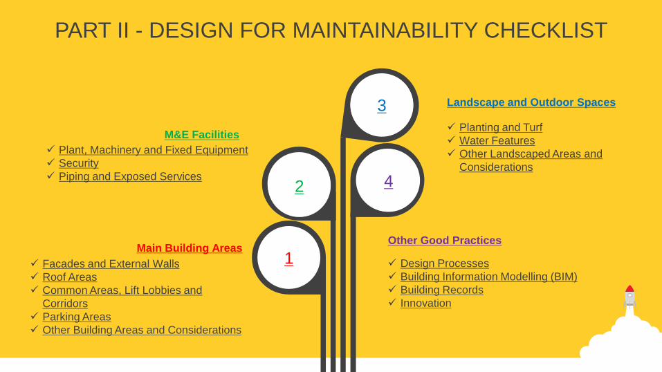
PART II - DESIGN FOR MAINTAINABILITY CHECKLIST
1
Plant, Machinery and Fixed Equipment
Security
Piping and Exposed Services
M&E Facilities
Facades and External Walls
Roof Areas
Common Areas, Lift Lobbies and
Corridors
Parking Areas
Other Building Areas and Considerations
Main Building Areas
Planting and Turf
Water Features
Other Landscaped Areas and
Considerations
Landscape and Outdoor Spaces
Design Processes
Building Information Modelling (BIM)
Building Records
Innovation
Other Good Practices
3
4 2

1. MAIN BUILDING AREAS
1. MAIN BUILDING AREAS
A. Façade and External Walls
Description of
provision
(Pls enclose relevant drawings, references, etc. where necessary
)
If No or Not Ap
plicable, please
clarify
A1. Access Y / N / NA
A1.1 General
The building envelope and appurtenances, including the exterior walls, roof, roof trellis, glass canopies, sky bridges, plant
ers, signboards, fixtures and equipment attached to or protruding from the façade, etc should be accessible for maintenan
ce.
A1.2 Protruding façade features
Minimise the use of extensive niches, large fins and ledges (e.g. >600mm) which are difficult to access for cleaning and m
aintenance. If the protrusions is too large (>2m), reach to the general façade might be affected.
A1.3 Internal Access
The design should facilitate minor cleaning and repair works to be carried out from interior, while major repair works can tak
e place from the outside to minimise inconvenience to the occupants.
For residential developments, the access for façade cleaning and repair work should not encroach into private spaces suc
h as the residents’ balconies, private enclosed spaces (PES) and private roof terraces.
A1.4 Allow façade/ window cleaning from the internal by providing appropriate openings for cleaners using handheld tools. Use
modularised windows panels which are not too large (max 750mm) for ease of cleaning within the reach of the cleaner’s
arm.
A1.5 External Access
The building should be designed with a façade access method that is suitable for the building geometry.
The building should require as few access systems as possible and yet achieve as high coverage as possible.

A. Façade and External Walls
A2.
Materials and Finishes
Y / N / NA
Description of
provision
(Attach relevant drawings, references, etc where nece
ssary)
If No or not applicab
le, please clarify
A2.1 General
Consider using materials that age well with time and weathering e.g. rustic stone finishes.
A2.2 Glass
Where Low-E coating is used, apply the coating on non- exposed glass (surface #2/#3) surface to avoid
being scratched and worn off.
A2.3 Minimize the use of non-planar or curvilinear glass surfaces which are difficult to clean and not readily av
ailable in the market.
A2.4 Paint Systems
Use suitable paint systems that could enhance weather protection and lengthen the cyclical period needed f
or façade re-painting (e.g. mineral or polyurethane paint systems).
A2.5 Fastenings and Fixings
Consider using materials that are not easily prone to corrosion or rust e.g. stainless steel.
A2.6 Selection of Materials
Minimise or eliminate the use of materials that are prone to deterioration when exposed to weathering (e.
g. plaster or calcium silicate board).

A. Façade and External Walls
A3.
Design and Detailing
Y / N / NA
Description of
provision
(Attach relevant drawings, references, etc where nece
ssary)
If No or not appli
cable, please cla
rify
A3.1 External Walls
Regularity of the façade surface’s plane will affect the even flow of runoff leading to water ponding, penetration a
nd staining problems. Design proper wall details to throw water off general façade surfaces to prevent staining and
minimise water penetration.
Provide drip edges to prevent streaking on wall soffit and glazing surfaces.
A3.2 Top surfaces of all walls to be graded to fall away from external face of walls to minimise streaking on the facade. T
he coping should overhang the rear side of the walls and comes with drip control to mitigate streaks on the back w
alls.
A3.3 Stone Panels
Stone panels should be mechanically fixed to avoid the use of plaster/ adhesive which may cause efflorescence.
A3.4 Stone panels should installed be in a way that allows for inspection of its hidden mechanical connections to ensur
e that it is not corroded or loose e.g. accessible for fibre-optics inspection.
A3.5 Weather Control Devices
Openings to external should incorporate appropriate weather control devices such as overhanging ledges, coping
s and rain screens to minimise rainwater ingress.
A3.6 Metallic Cladding and Fixtures
Minimise the use of metallic cladding and wrapping around external building components such as beams and col
umns near loading/ unloading areas where high delivery volume is expected.
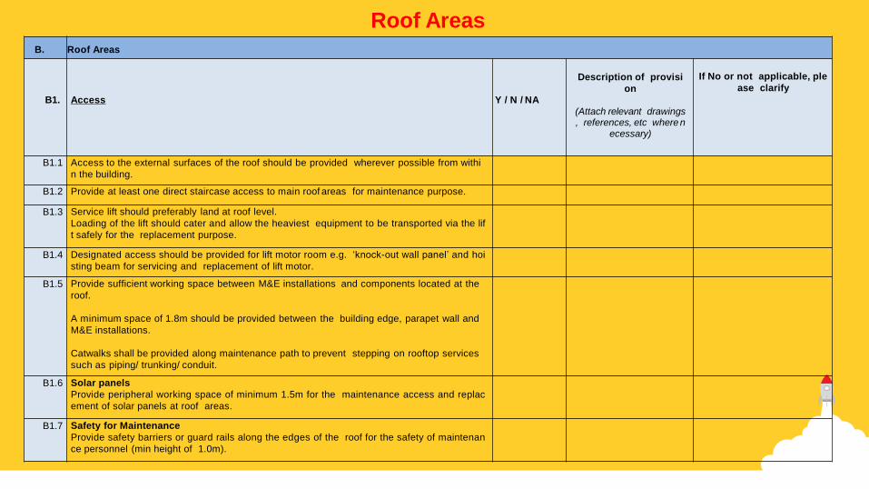
B. Roof Areas
B1.
Access
Y / N / NA
Description of provisi
on
(Attach relevant drawings, references, etc where n
ecessary)
If No or not applicable, ple
ase clarify
B1.1 Access to the external surfaces of the roof should be provided wherever possible from withi
n the building.
B1.2 Provide at least one direct staircase access to main roof areas for maintenance purpose.
B1.3 Service lift should preferably land at roof level.
Loading of the lift should cater and allow the heaviest equipment to be transported via the lif
t safely for the replacement purpose.
B1.4 Designated access should be provided for lift motor room e.g. ‘knock-out wall panel’ and hoi
sting beam for servicing and replacement of lift motor.
B1.5 Provide sufficient working space between M&E installations and components located at the
roof.
A minimum space of 1.8m should be provided between the building edge, parapet wall and
M&E installations.
Catwalks shall be provided along maintenance path to prevent stepping on rooftop services
such as piping/ trunking/ conduit.
B1.6 Solar panels
Provide peripheral working space of minimum 1.5m for the maintenance access and replac
ement of solar panels at roof areas.
B1.7 Safety for Maintenance
Provide safety barriers or guard rails along the edges of the roof for the safety of maintenan
ce personnel (min height of 1.0m).
Roof Areas
B. Roof Areas
B1.
Access
Y / N / NA
Description of provi
sion
(Attach relevant drawings, references, etc wher
e necessary)
If No or not applicable, pl
ease clarify
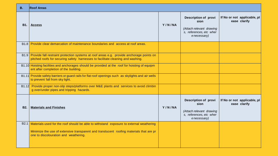
B1.8 Provide clear demarcation of maintenance boundaries and access at roof areas.
B1.9 Provide fall restraint protection systems at roof areas e.g. provide anchorage points on
pitched roofs for securing safety harnesses to facilitate cleaning and washing.
B1.10 Hoisting facilities and anchorages should be provided at the roof for hoisting of equipm
ent after completion of the building.
B1.11 Provide safety barriers or guard rails for flat roof openings such as skylights and air wells
to prevent fall from sky light.
B1.12 Provide proper non-slip steps/platforms over M&E plants and services to avoid climbin
g over/under pipes and tripping hazards.
B2.
Materials and Finishes
Y / N / NA
Description of provi
sion
(Attach relevant drawings, references, etc wher
e necessary)
If No or not applicable, pl
ease clarify
B2.1 Materials used for the roof should be able to withstand exposure to external weathering
Minimize the use of extensive transparent and translucent roofing materials that are pr
one to discolouration and weathering.
B. Roof Areas
B3.
Design and Detailing
Y / N / NA
Description of provisi
on
(Attach relevant drawings, references, etc where n
ecessary)
If No or not applicable, ple
ase clarify
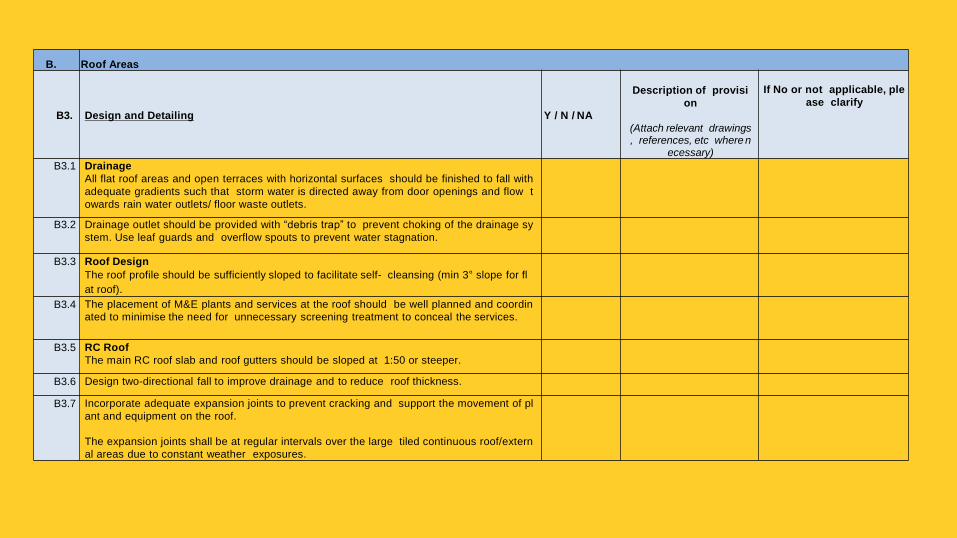
B3.1 Drainage
All flat roof areas and open terraces with horizontal surfaces should be finished to fall with
adequate gradients such that storm water is directed away from door openings and flow t
owards rain water outlets/ floor waste outlets.
B3.2 Drainage outlet should be provided with “debris trap” to prevent choking of the drainage sy
stem. Use leaf guards and overflow spouts to prevent water stagnation.
B3.3 Roof Design
The roof profile should be sufficiently sloped to facilitate self- cleansing (min 3° slope for fl
at roof).
B3.4 The placement of M&E plants and services at the roof should be well planned and coordin
ated to minimise the need for unnecessary screening treatment to conceal the services.
B3.5 RC Roof
The main RC roof slab and roof gutters should be sloped at 1:50 or steeper.
B3.6 Design two-directional fall to improve drainage and to reduce roof thickness.
B3.7 Incorporate adequate expansion joints to prevent cracking and support the movement of pl
ant and equipment on the roof.
The expansion joints shall be at regular intervals over the large tiled continuous roof/extern
al areas due to constant weather exposures.

C. Common Areas, Lift Lobbies and Corridors
C1.
Access
Y / N / NA
Description of provis
ion
(Attach relevant drawings, references, etc where
necessary)
If No or not applica
ble, please clarify
C1.1 Air Well and Atrium
a) Avoid creating constricted areas, air wells and atrium which are difficult to access and maintain.
b) Provide at least 1.2m clear width access space.
c) Use materials of non-slip nature in area which may be affected during wet weather.
d) Provide maintenance tracks systems around large voids and air wells. Safe access to be provided for “fire
detection devices” for the purpose of testing, servicing and replacement.
e) BMU Systems should be designed such that all façade surfaces can be accessed and within reach from g
ondola cradle.
f) Avoid high volume voids or “soft storeys” with “flying” beams with no easy access for maintenance.
C1.2 Ceiling Spaces and Height
Minimize extensive lobby areas with high and deep ceiling spaces (e.g. > 5m) which are difficult to access for
maintenance.
C1.3 Where ceiling spaces that require maintenance exceeds 5m in height, provide catwalks, elevated platforms an
d/or unobstructed access route for maintenance equipment and vehicles e.g. scissors lift and mobile elevate
d platforms.
To facilitate access to high ceiling spaces in sky terraces, provide a service lift of adequate capacity to transp
ort the maintenance equipment and vehicles.
C1.4 Provide signs and location indicators for services located above high ceiling areas. Services above suspende
d ceiling to be provided with proper access and marked on as-built drawings.
C1.5 Where electrical control boards, valves, water and sanitary pipes are installed at high ceiling areas, provide p
ermanent maintenance access and platform for accessing equipment.
C1.6 Access panels should be provided to ensure concealed services are fully serviceable.
Common Areas, Lift Lobbies and Corridors
C. Common Areas, Lift Lobbies and Corridors
C2.
Materials and Finishes
Y / N / NA
Description of
provision
(Attach relevant drawings, references, etc where nece
ssary)
If No or not applic
able, please clarif
y
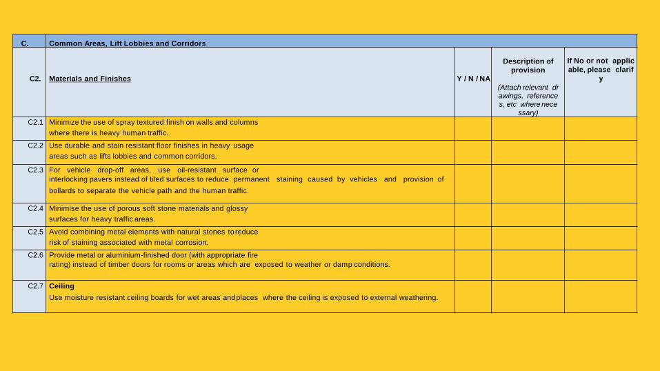
C2.1 Minimize the use of spray textured finish on walls and columns
where there is heavy human traffic.
C2.2 Use durable and stain resistant floor finishes in heavy usage
areas such as lifts lobbies and common corridors.
C2.3 For vehicle drop-off areas, use oil-resistant surface or
interlocking pavers instead of tiled surfaces to reduce permanent staining caused by vehicles and provision of
bollards to separate the vehicle path and the human traffic.
C2.4 Minimise the use of porous soft stone materials and glossy
surfaces for heavy traffic areas.
C2.5 Avoid combining metal elements with natural stones to reduce
risk of staining associated with metal corrosion.
C2.6 Provide metal or aluminium-finished door (with appropriate fire
rating) instead of timber doors for rooms or areas which are exposed to weather or damp conditions.
C2.7 Ceiling
Use moisture resistant ceiling boards for wet areas and places where the ceiling is exposed to external weathering.

C. Common Areas, Lift Lobbies and Corridors
C3.
Design and Detailing
Y / N / NA
Description of
provision
(Attach relevant drawings, references, etc where nece
ssary)
If No or not applica
ble, please clarify
C3.1 Linkways and Drop-off Areas
Linkways and drop-off areas should provide sufficient roof gradient for water run-off and minimise the use of fl
at roofs.
C3.2 The design of linkways and drop-off porches should adopt a width to height ratio of 1: 1 to minimise rainwater
entry.
C3.3 Provide concrete curb / collar at the base of metal columns to minimise contact with water and reduce corrosi
on.
C3.4 Where high openings are provided, drop panels and weather proof louvers should be provided to reduce impa
ct of weathering.
C3.5 Entrance
Provide sheltered area or canopy with a depth of at least 2 times of the entrance width for weather protection.
Entrance floor finishes should have proper screed to fall to facilitate water discharge.
C3.6 Provide heavy-duty dust control floor mats at the main entrance to reduce entry of dirt and dust into buildings.
Floor mat should flush with the floor finishes to prevent tripping hazards.
C3.7 External Floor
Timber/ concrete floor slabs should be easily removed for inspection and maintenance. Consider the use of c
omposite or synthetic wood for ease of maintenance.
C3.8 All ground floor and flat surfaces exposed directly or indirectly to weather should be designed with falls and gr
adient to promote discharge of water to the external drains and scuppers.
C3.9 Minimise corners and cavities which are inaccessible to cleaning machines.
C3.10 Ceiling
Minimise the use of monolithic ceiling design (joint-less without access) which are more costly and tedious to r
epair and maintain. Use suspended modular ceiling panels that are easily demountable for replacement and
maintenance.
C3.11 Provide appropriate warning signs for maintenance crew to prevent stepping on ceiling board.
C3.12 Where metal ceiling panels are used, they should be designed to prevent sagging and withstand wind loads.
D. Parking Areas
D1.
Access
Y / N / NA
Description of
provision
(Attach relevant drawings, references, etc where nece
ssary)
If No or not applica
ble, please clarify
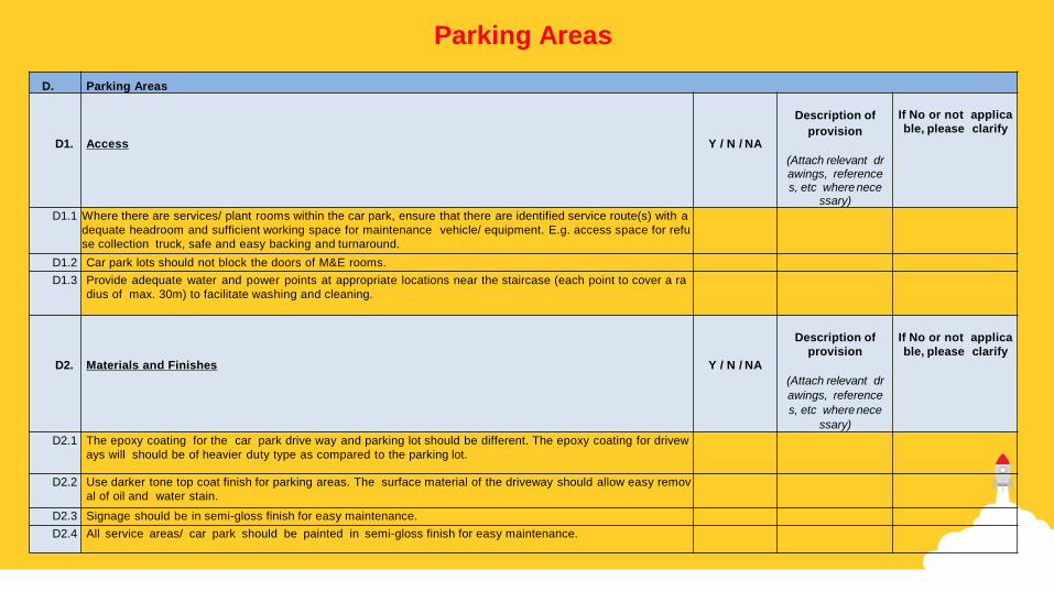
D1.1 Where there are services/ plant rooms within the car park, ensure that there are identified service route(s) with a
dequate headroom and sufficient working space for maintenance vehicle/ equipment. E.g. access space for refu
se collection truck, safe and easy backing and turnaround.
D1.2 Car park lots should not block the doors of M&E rooms.
D1.3 Provide adequate water and power points at appropriate locations near the staircase (each point to cover a ra
dius of max. 30m) to facilitate washing and cleaning.
D2.
Materials and Finishes
Y / N / NA
Description of
provision
(Attach relevant dr
awings, reference
s, etc where nece
ssary)
If No or not applica
ble, please clarify
D2.1 The epoxy coating for the car park drive way and parking lot should be different. The epoxy coating for drivew
ays will should be of heavier duty type as compared to the parking lot.
D2.2 Use darker tone top coat finish for parking areas. The surface material of the driveway should allow easy remov
al of oil and water stain.
D2.3 Signage should be in semi-gloss finish for easy maintenance.
D2.4 All service areas/ car park should be painted in semi-gloss finish for easy maintenance.
Parking Areas
D. Parking Areas
Description of pr
ovision
(Attach relevant drawings, references, etc where necessar
y)
If No or not appl
icable, please cl
arify
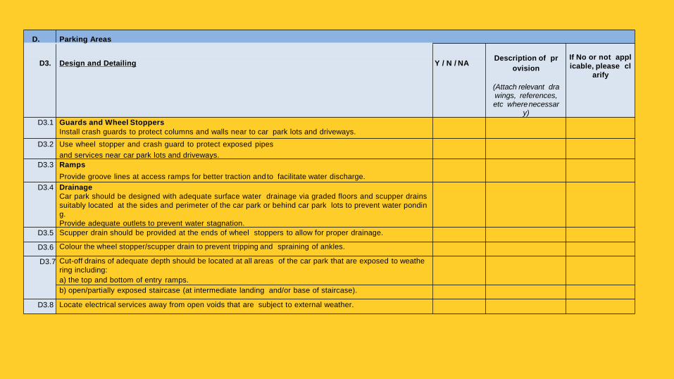
D3. Design and Detailing Y / N / NA
D3.1 Guards and Wheel Stoppers
Install crash guards to protect columns and walls near to car park lots and driveways.
D3.2 Use wheel stopper and crash guard to protect exposed pipes
and services near car park lots and driveways.
D3.3 Ramps
Provide groove lines at access ramps for better traction and to facilitate water discharge.
D3.4 Drainage
Car park should be designed with adequate surface water drainage via graded floors and scupper drains
suitably located at the sides and perimeter of the car park or behind car park lots to prevent water pondin
g.
Provide adequate outlets to prevent water stagnation.
D3.5 Scupper drain should be provided at the ends of wheel stoppers to allow for proper drainage.
D3.6 Colour the wheel stopper/scupper drain to prevent tripping and spraining of ankles.
D3.7 Cut-off drains of adequate depth should be located at all areas of the car park that are exposed to weathe
ring including:
a) the top and bottom of entry ramps.
b) open/partially exposed staircase (at intermediate landing and/or base of staircase).
D3.8 Locate electrical services away from open voids that are subject to external weather.

E. Other Building Areas and Considerations
Description of
provision
(Attach relevant dr
awings, reference
s, etc where neces
sary)
If No or not a
pplicable, plea
se clarify
E1. Access Y / N / NA
E1.1 Washrooms
Hand soap dispensers should be fitted above instead of under the vanity top for ease of replacement/refill.
E1.2 Washing dispensers (soap/hand towel)/hand dryer to be placed next to wash basin.
E1.3 To facilitate floor cleaning, use wall-mounted wash basins and water cisterns.
E1.4 Consider suspending the cubicle partitions from the top to facilitate floor cleaning and prevent the partition panels from constant c
ontact with damp floor.
E1.5 Supporting Facilities for Cleaners
Provide at least one service lift to facilitate access of cleaning machines and equipment.
E1.6 Provide a store room on each level for storage of daily use cleaning tools/equipment, chemicals and supplies.
Equip these store room with utilities supply for washing of cleaning tools and equipment, as well as splash proof socket points
to facilitate the charging of cleaning tools/equipment.
E.1.7 Provide a designated room of sufficient size for cleaners to rest and store personal belongings.
E.1.8 Provide a central store room/area for storage of large cleaning machines, e.g. ride-on sweeper/scrubber, etc, which is easily ac
cessible via service lift. Equip these store room with utilities supply for washing of cleaning machines and dosing of chemical/de
tergent, as well as splash proof socket points to facilitate the charging of cleaning machines
E1.9 Service Ledge for External Air-conditioning Unit
Where maintenance access to the service ledge is via windows or wall apertures, the size of the openings should allow safe a
nd easy access for maintenance personnel carrying tools, equipment and component parts. Maintenance activities should not
require the dismantling of services and building elements.
E1.10 Provide safety barriers or guardrails along the edges of the service ledge for the safety of maintenance personnel.
Other Building Areas and Considerations
E. Other Building Areas and Considerations
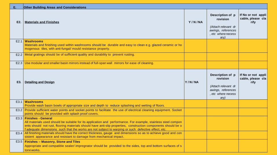
E2.
Materials and Finishes
Y / N / NA
Description of p
rovision
(Attach relevant drawings, references, etc where necess
ary)
If No or not appli
cable, please cla
rify
E2.1 Washrooms
Materials and finishing used within washrooms should be durable and easy to clean e.g. glazed ceramic or ho
mogenous tiles, with anti-fungal/ mould resistance property.
E2.2 Metal gratings should be of sufficient quality and durability to prevent rusting.
E2.3 Use modular and smaller basin mirrors instead of full-span wall mirrors for ease of cleaning.
E3.
Detailing and Design
Y / N / NA
Description of p
rovision
(Attach relevant dr
awings, references
, etc where necess
ary)
If No or not appli
cable, please cla
rify
E3.1 Washrooms
Provide wash basin bowls of appropriate size and depth to reduce splashing and wetting of floors.
E3.2 Provide sufficient water points and socket points to facilitate the use of electrical cleaning equipment. Socket
points should be provided with splash proof covers.
E3.3 Finishes - General
All materials used should be suitable for its application and performance. For example, stainless steel compon
ents should not rust, flooring materials should have anti-slip properties, construction components should be o
f adequate dimensions such that the works are not subject to warping or such defective effect, etc.
E3.4 All finishing materials should have the correct thickness, gauge and dimensions so as to achieve good and con
sistent appearance and resistant to damage from mechanical impact.
E3.5 Finishes – Masonry, Stone and Tiles
Appropriate and compatible sealer/ impregnator should be provided to the sides, top and bottom surfaces of s
tone works.
E. Other Building Areas and Considerations
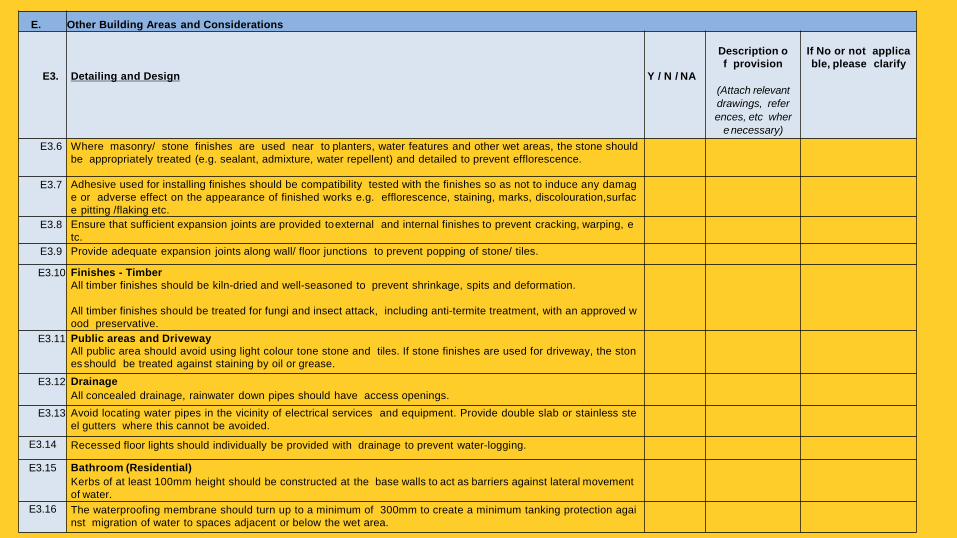
E3.
Detailing and Design
Y / N / NA
Description o
f provision
(Attach relevant
drawings, refer
ences, etc wher
e necessary)
If No or not applica
ble, please clarify
E3.6 Where masonry/ stone finishes are used near to planters, water features and other wet areas, the stone should
be appropriately treated (e.g. sealant, admixture, water repellent) and detailed to prevent efflorescence.
E3.7 Adhesive used for installing finishes should be compatibility tested with the finishes so as not to induce any damag
e or adverse effect on the appearance of finished works e.g. efflorescence, staining, marks, discolouration,surfac
e pitting /flaking etc.
E3.8 Ensure that sufficient expansion joints are provided to external and internal finishes to prevent cracking, warping, e
tc.
E3.9 Provide adequate expansion joints along wall/ floor junctions to prevent popping of stone/ tiles.
E3.10 Finishes - Timber
All timber finishes should be kiln-dried and well-seasoned to prevent shrinkage, spits and deformation.
All timber finishes should be treated for fungi and insect attack, including anti-termite treatment, with an approved w
ood preservative.
E3.11 Public areas and Driveway
All public area should avoid using light colour tone stone and tiles. If stone finishes are used for driveway, the ston
es should be treated against staining by oil or grease.
E3.12 Drainage
All concealed drainage, rainwater down pipes should have access openings.
E3.13 Avoid locating water pipes in the vicinity of electrical services and equipment. Provide double slab or stainless ste
el gutters where this cannot be avoided.
E3.14 Recessed floor lights should individually be provided with drainage to prevent water-logging.
E3.15 Bathroom (Residential)
Kerbs of at least 100mm height should be constructed at the base walls to act as barriers against lateral movement
of water.
E3.16 The waterproofing membrane should turn up to a minimum of 300mm to create a minimum tanking protection agai
nst migration of water to spaces adjacent or below the wet area.
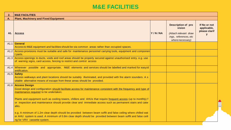
2. M&E FACILITIES
A. Plant, Machinery and Fixed Equipment
A1.
Access
Y / N / NA
Description of pro
vision
(Attach relevant draw
ings, references, etc
where necessary)
If No or not
applicable,
please clarif
y
A1.1 General
Access to M&E equipment and facilities should be via common areas rather than occupied spaces.
A1.2 Access provisions must be suitable and safe for maintenance personnel carrying tools, equipment and componen
t parts.
A1.3 Access openings to ducts, voids and roof areas should be properly secured against unauthorised entry. e.g. use
of warning signs, card access, fencing to restrict and control access
A1.4 Wherever possible and appropriate, M&E elements and services should be labelled and marked for easy id
entification.
A1.5 Safety
Access walkways and plant locations should be suitably illuminated, and provided with fire alarm sounders. A s
uitable alternative means of escape from these areas should be provided.
A1.6 Access Design
Good design and configuration should facilitate access for maintenance consistent with the frequency and type of
maintenance required to be undertaken.
Plants and equipment such as cooling towers, chillers and AHUs that require frequent access (up to monthly) f
or inspection and maintenance should provide clear and immediate access such as permanent stairs and catw
alks.
e.g. A minimum of 1.2m clear depth should be provided between beam soffit and false ceiling where chilled wat
er AHU system is used. A minimum of 0.8m clear depth should be provided between beam soffit and false ceili
ng for VRV cassette system.
M&E FACILITIES

A. Plant, Machinery and Fixed Equipment
A2.
Materials and Fittings
Y / N / NA
Description of
provision
(Attach relevant dr
awings, reference
s, etc where nece
ssary)
If No or not
applicable,
please clarif
y
A2.1 Service rooms and corridors should use darker tone epoxy top coat for the floor finishes.
A2.2 Provide metal chequer plate wall panels (up to 1.2m high) for heavy duty surface protection in areas subject to
frequent, heavy wheeled traffic e.g. service corridors, loading areas.
A2.3 Door kick plate should be provided for M&E rooms.
A2.4 Weather-resistant material (e.g. aluminium doors) should be provided for all services doors exposed to weatheri
ng. Service doors shall also be of suitable fire-rating.
A2.5 Lighting switches and socket outlets for M&E rooms should be durable and certified with Safety Mark. Use IP ra
ted switches and socket outlets.
A3.
Design and Detailing
Y / N / NA
Description of
provision
(Attach relevant dr
awings, reference
s, etc where nece
ssary)
If No or not
applicable,
please clarif
y
A3.1 Plant Rooms
M&E plant rooms should be well-lit and sufficiently ventilated. To provide backup emergency lighting in event of p
ower failure. Adequate lighting should be provided to facilitate night maintenance. Electrical systems and Emerg
ency power should be designed for shutdown maintenance.
A3.2 Ductworks/ pipes across floor
Avoid ductwork/ pipes crossing plant room floors so as to minimise trip hazards and damage due to maintenan
ce personnel stepping on the duct work/ pipes. All pipe and duct works should have isolation valves and be pr
operly identified to enable tracing for maintenance and troubleshooting.
A3.3 Mechanical Installations
Provide appropriate labels and details of weights, lifting points to facilitate replacement and removal.

B. Security
B1.
Access and Control
Y / N / NA
Description of provis
ion
(Attach relevant drawing
s, references, etc where
necessary)
If No or not appli
cable, please cla
rify
B1.1 Central control console should be located in areas with 24- hours manning.
B1.2 Locate the fire command centre and security centre to oversee at least one main ingress/ egress point
or critical area. The FCC should be designed such that the operator is able to view all alarm signage from his sitting p
osition instead of having to turn round to see the alarm soundings.
B1.3 Use turnstile with proximity security access passes.
B1.4 Remote monitoring/ CCTV
Use CCTV surveillance technology with motion sensing alert to reduce security man count. Provide C
CTV surveillance at all common and critical areas including but not limited to:
Car park
Lift lobbies
Entries into staircases
Main lobbies
All exits of the building/ car park
Last landing of escape staircase staircases
Loading/unloading area
Mailroom
Essential plants and equipment rooms
B1.5 Visitors Management System
Use computer-based Visitors Management System to record the usage of the facilities by specific visit
ors and provide documentation of visitor’s whereabouts.
B1.6 Security Access to Critical Areas
Provision of programmable door access to all critical areas
B1.7 Security Patrol Layout Route
Consider a proper routing plan and for security patrols to cover all critical areas. This should include de
signated movement corridors for vehicles and visitors in the vicinity
Security
C. Piping and Exposed Services
C1.
Access
Y / N / NA
Description of pr
ovision
(Attach relevant drawings, references, etc where necessar
y)
If No or not ap
plicable, plea
se clarify
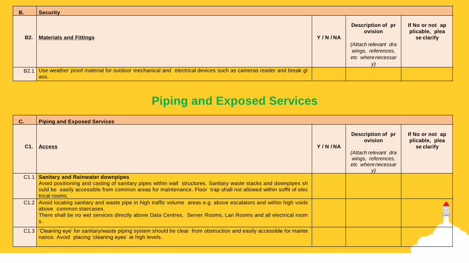
C1.1 Sanitary and Rainwater downpipes
Avoid positioning and casting of sanitary pipes within wall structures. Sanitary waste stacks and downpipes sh
ould be easily accessible from common areas for maintenance. Floor trap shall not allowed within soffit of elec
trical rooms.
C1.2 Avoid locating sanitary and waste pipe in high traffic volume areas e.g. above escalators and within high voids
above common staircases.
There shall be no wet services directly above Data Centres, Server Rooms, Lan Rooms and all electrical room
s.
C1.3 ‘Cleaning eye’ for sanitary/waste piping system should be clear from obstruction and easily accessible for mainte
nance. Avoid placing ‘cleaning eyes’ at high levels.
B. Security
B2.
Materials and Fittings
Y / N / NA
Description of pr
ovision
(Attach relevant dra
wings, references,
etc where necessar
y)
If No or not ap
plicable, plea
se clarify
B2.1 Use weather proof material for outdoor mechanical and electrical devices such as cameras reader and break gl
ass.
Piping and Exposed Services

C. Piping and Exposed Services
C2.
Materials and Fittings
Y / N / NA
Description of pr
ovision
(Attach relevant drawings, references, etc where necessar
y)
If No or not app
licable, please
clarify
C2.1 Sanitary and Rainwater downpipes
Provide anti-corrosive material for pipings and installations (e.g. UPVC pipes).
Use materials that meet quality specification that resist staining and rusting (e.g. suitable grade of stainle
ss steel).
C2.2 Signage
All external signage should be of weather proof type.
C3.
Design and Detailing
Y / N / NA
Description of pr
ovision
(Attach relevant drawings, references, etc where necessar
y)
If No or not app
licable, please
clarify
C3.1 Sanitary and Rainwater downpipes
Provide labelling and colour coding of piping and conduits in accordance to universal standards.
Provide directional signs and valve status on pipelines for ease of identification.
3. LANDSCAPE AND OUTDOOR SPACES
A. Planting and Turf
A1.
Access
Y / N / NA
Description of pr
ovision
(Attach relevant drawings, references, etc where necessar
y)
If No or not applica
ble, please clarify
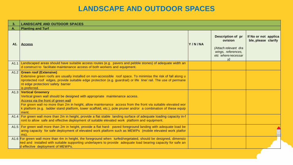
A1.1 Landscaped areas should have suitable access routes (e.g. pavers and pebble stones) of adequate width an
d construct to facilitate maintenance access of both workers and equipment.
A1.2 Green roof (Extensive)
Extensive green roofs are usually installed on non-accessible roof space. To minimise the risk of fall along u
nprotected roof edges, provide suitable edge protection (e.g. guardrail) or life line/ rail. The use of permane
nt edge protection/ safety barrier
is preferred.
A1.3 Vertical Greenery
Vertical green wall should be designed with appropriate maintenance access.
Access via the front of green wall
For green wall no more than 2m in height, allow maintenance access from the front via suitable elevated wor
k platform (e.g. ladder stand platform, tower scaffold, etc.), pole pruner and/or a combination of these equip
ment.
A1.4 For green wall more than 2m in height, provide a flat stable landing surface of adequate loading capacity in-f
ront to allow safe and effective deployment of suitable elevated work platform and equipment.
A1.5 For green wall more than 2m in height, provide a flat hard- paved foreground landing with adequate load be
aring capacity for safe deployment of elevated work platform such as MEWPs (mobile elevated work platfor
ms).
A1.6 For green wall more than 4m in height, the foreground when turfed/vegetated, should be designed, dimensio
ned and installed with suitable supporting underlayers to provide adequate load bearing capacity for safe an
d effective deployment of MEWPs.
LANDSCAPE AND OUTDOOR SPACES

A. Planting and Turf
A2.
Materials and Finishes
Y / N / NA
Description of
provision
(Attach relevant dr
awings, reference
s, etc where nece
ssary)
If No or not ap
plicable, please
clarify
A2.1 General
Consider the use of durable and stain-resistant materials (e.g. pebblewash, dark stone finishes for landscape areas).
A2.2 Plants selection
Select plant species in response to the expected environmental conditions e.g. plant appropriately for sunny/ shady areas,
wet grounds, high traffic areas, etc.
A2.3 For vegetation abutting water features and water bodies, avoid selecting plant species with excessive shedding of leaves.
A2.4 Avoid using plant species with invasive roots system near basement walls.
Proper provision of roof barrier for such basement walls will help further safeguard the built structure’s integrity.
A2.5 Consider the use of synthetic turf for surface areas with high level of human traffic and activities (e.g. school fields), as well
as those areas with difficulty of access (e.g. green islands within pool/ water feature).
A2.6 Some plants species (e.g. species of bromeliad, alocasia) do trap water and will require regular monitoring for signs of mo
squito breeding.
In areas where plant inspection is infrequent and/or cannot be effectively conducted, use of such plant species should be
avoided.
A2.7 Plants suspected of harbouring pests and disease pathogens should not be introduced into any new or existing planting
areas, as eradication of pests and pathogens once established will be difficult.
Do not replace with the same plant species after root or wilt infections. If the same plant species is desired, all the conta
minated soil should be replaced with clean soil before planting. Resistant varieties of the same species should be consid
ered.
A2.8 Test Plots
Prior to the skyrise greenery installation, set up plant test plots (mock-up surfaces, etc.) in consultation with skyrise greener
y consultants to ascertain the horticulture performance of selected greenery systems and plant species.
The test plots will aid in identifying the suitable plant species as well as manage the building owners’ and users’ expectat
ions of the relevant greenery systems and the subsequent maintenance.
A2.9 Irrigation system
Irrigation pipes and systems should be designed with adequate strength and durability.

A. Planting and Turf
Description of
provision
(Attach relevant dr
awings, reference
s, etc where nece
ssary)
If No or not a
pplicable, ple
ase clarify A3. Design and Detailing Y / N / NA
A3.1 Planters
Provide sufficient soil depth for the roots to grow. In general, groundcovers and shrubs require a soil depth of between 3
00mm and 500mm depth, while small and medium trees (mature heights of 8m to 10m) require a depth of between 1m t
o 1.5m.
A3.2 Drainage
Planters should be designed with effective surface drainage systems. Avoid large overall difference in invert level due to
long run of surface drain to reach the discharge point.
A3.3 Avoid un-edged planting areas. Enclose planting within planter boxes to reduce soil erosion and spillage onto common a
reas.
A3.4 Landscape footpaths should be at least 50mm higher than the sump pit top level for effective drainage. The footpaths sh
ould be sloped to fall effectively to the nearest sump drain.
A3.5 The roof slab should be sloped towards the drainage outlet with silt control system.
Waterproofing membrane should be properly installed around the drain opening so that water drains off from the waterp
roofing membrane to the roof outlet. Plants should not be allowed to grow into guttering.
A3.6 Ensure rainwater runoff from roof of shelters and structures does not fall directly on planting (provide materials to reduce i
mpact if necessary, e.g. gravel).
A3.7 Provide appropriate drainage outlets for vertical greenery installations so as to avoid unsightly puddles forming at the b
ase of the green wall.
Consider using drainage trays at the base of the installation or locating the green wall strategically at a natural drainage o
utlet.
A3.8 Turf
Turf requires regular mowing. Avoid planting turf right up to the base of the tree to minimise the risk of mechanical dama
ge to the tree bark during turf mowing.

B. Water Features
B1.
Access
Y / N / NA
Description of pr
ovision
(Attach relevant dra
wings, references,
etc where necessar
y)
If No or not appl
icable, please cl
arify
B1.1 Provide access routes of adequate width for the maintenance of water features and landscape elements.
B1.2 Provide adequate and safe access to pump room, balancing tanks and other pump equipment which serves the wat
er features.
Adequate lighting and ventilation should be provided for such spaces.
B2.
Materials and Finishes
Y / N / NA
Description of pr
ovision
(Attach relevant drawings, references, etc where necessar
y)
If No or not appl
icable, please cl
arify
B2.1 Water features should be built of durable materials to withstand harsh weather conditions.
B2.2 Use armoured cable for outdoor/ underground electric supply
to water features. Underwater lights / devices should be of minimum IP 68 rating and be easily accessi
ble for
maintenance.
Water Features
C. Other Landscaped Areas and Considerations
C1.
Access
Y / N / NA
Description of
provision
(Attach relevant drawings, references, etc where necess
ary)
If No or not ap
plicable, pleas
e clarify
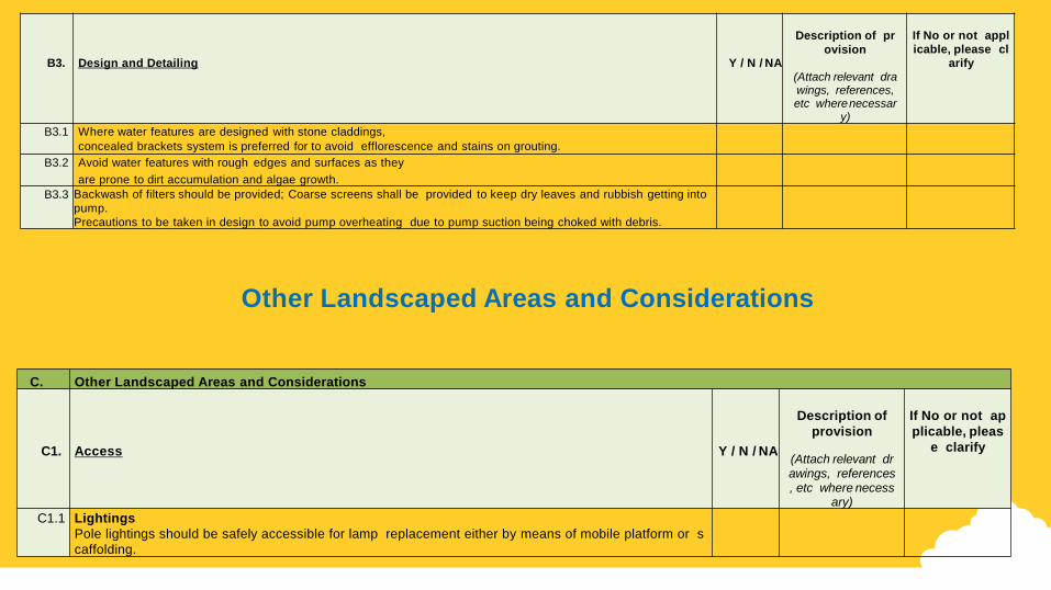
C1.1 Lightings
Pole lightings should be safely accessible for lamp replacement either by means of mobile platform or s
caffolding.
B3.
Design and Detailing
Y / N / NA
Description of pr
ovision
(Attach relevant drawings, references, etc where necessar
y)
If No or not appl
icable, please cl
arify
B3.1 Where water features are designed with stone claddings,
concealed brackets system is preferred for to avoid efflorescence and stains on grouting.
B3.2 Avoid water features with rough edges and surfaces as they
are prone to dirt accumulation and algae growth.
B3.3 Backwash of filters should be provided; Coarse screens shall be provided to keep dry leaves and rubbish getting into
pump.
Precautions to be taken in design to avoid pump overheating due to pump suction being choked with debris.
Other Landscaped Areas and Considerations

4. OTHER GOOD PRACTICES
A.
Design Processes
Y / N / NA
Description of
provision
(Attach relevant drawings, references, etc where
necessary)
If No or not ap
plicable, please
clarify
A1. Design Brief
Provide a clear design brief for maintenance performance and operations.
A2. Participation of maintenance managers
Allow maintenance professionals to participate throughout the design and construction phases, including input to and r
eview of design drawings and specifications.
B. Building Information Modelling (BIM)
B1. Use BIM to facilitate integration of relevant information on facility and asset management and better coordinated docu
mentation for maintenance operations.
C. Building Records
C1. As-built records should be prepared, regularly updated and kept for record purposes. To facilitate proper management
of maintenance, the records should provide information in sufficient details of building structures and services. All mai
ntenance personnel should be made aware of such records.
D. Innovation
D1. Self-cleansing Facade
Consider the use of cement or façade panels with self- cleansing properties (e.g. titanium dioxide coating) to reduce th
e frequency of façade cleaning.
D2. Pneumatic Refuse Collection System (PRCS)
Consider the use of PRCS to improve productivity in refuse collection and disposal. PRCS can be fitted with sensors to
monitor waste disposal patterns and the volume. The frequency of waste collection can be adjusted based on the volu
me of waste collected.
D3. Smart Lighting/Sensor
Consider the use of lighting with sensors to help
understand human traffic patterns and optimize/reduce the provision of lighting in low traffic areas. This can help
to reduce energy and maintenance.
OTHER GOOD PRACTICES

PART III - MAINTENANCE STRATEGY REPORT
2
3
1
4
Maintenance Strategy Report
Report content
Consultation with Stakeholders
Updates and Handing Over

Maintenance Strategy Report
It is important to ensure that all parties understand future
maintenance obligations before the building has been
constructed. Notwithstanding the recommendations in the
Design for Maintainability Checklist, designers are advised
to prepare a Maintenance Strategy Report at the early
stage of the design process to document their
maintenance philosophy and operational assumptions.

Report
Content
In the Maintenance Strategy Report, designers should state their propo
sed maintenance strategies which typically include, but not limited to t
he following:
unique requirements of the project
areas requiring maintenance access (including spatial and structu
ral requirements, etc)
anticipated maintenance tasks and frequency
particular materials/ equipment that have specific maintenance re
quirements
proposed/ assumed maintenance methodology (equipment, meth
ods, etc) maintenance activities that create specific risks and/or safe
ty issues to maintenance personnel and building users
The report is not intended to be a voluminous paperwork. Information p
rovided in the report should be clear, concise and in a format (e.g. des
ign notes, drawings, tables, charts and written information - see examp
le below) suitable for parties involved in constructing the building, opera
ting the premises or carrying out maintenance works.

Consultation
with Stakeho
lders In developing the Maintenance Strategy Report, designers should
consult relevant stakeholders such as building managers, maintena
nce contractors and end-users who can advise on the safe, appropr
iate and cost-effective solutions. The consultative process will ensur
e that the proposed maintenance methodology is coherent with the
future maintenance regime and that all stakeholders are made awar
e and amenable to the strategy.

Updates and Handing Over
Updates should be made to the report to document the revisions made and eventual maintenance strategies adopted during the design development and construction phases.
Upon construction completion, the Maintenance Strategy Report should be handed to the building owner/ manager and used as a reference for contractors undertaking the maintenance work.

Centre for Urban Greenery & Ecology, 2015.
Sustainable Landscape. Singapore
Centre for Urban Greenery & Ecology,
2015. CS E11:2014 – Guidelines on
Design for Safety of Skyrise Greenery.
Singapore
REFERENCES

Thank you