Embed Size (px)
Citation preview
Design for Durability
DN-STR-03012 December 2010
Design Standards DN
TRANSPORT INFRASTRUCTURE IRELAND (TII) PUBLICATIONS
About TII Transport Infrastructure Ireland (TII) is responsible for managing and improving the country’s national road and light rail networks. About TII Publications TII maintains an online suite of technical publications, which is managed through the TII Publications website. The contents of TII Publications is clearly split into ‘Standards’ and ‘Technical’ documentation. All documentation for implementation on TII schemes is collectively referred to as TII Publications (Standards), and all other documentation within the system is collectively referred to as TII Publications (Technical). This system replaces the NRA Design Manual for Roads and Bridges (NRA DMRB) and the NRA Manual of Contract Documents for Road Works (NRA MCDRW). Document Attributes Each document within TII Publications has a range of attributes associated with it, which allows for efficient access and retrieval of the document from the website. These attributes are also contained on the inside cover of each current document, for reference. For migration of documents from the NRA and RPA to the new system, each current document was assigned with new outer front and rear covers. Apart from the covers, and inside cover pages, the documents contain the same information as previously within the NRA or RPA systems, including historical references such as those contained within NRA DMRB and NRA MCDRW. Document Attributes
TII Publication Title Design for Durability TII Publication Number
DN-STR-03012
Activity Design (DN) Document Set Standards
Stream Structures (STR) Publication Date December 2010
Document Number
03012 Historical Reference
NRA BD 57
NRA DMRB and MCDRW References For all documents that existed within the NRA DMRB or the NRA MCDRW prior to the launch of TII Publications, the NRA document reference used previously is listed above under ‘historical reference’. The TII Publication Number also shown above now supersedes this historical reference. All historical references within this document are deemed to be replaced by the TII Publication Number. For the equivalent TII Publication Number for all other historical references contained within this document, please refer to the TII Publications website.
Volume 1 Section 3
Part 7
NRA BD 57/10
Design for Durability
December 2010
St. Martin’s House, Waterloo Road, Dublin 4. Tel:+353 1 660 2511 Fax +353 1 668 0009 Email : [email protected] Web : www.nra.ie
Summary:
This Standard sets out the requirements for the design of bridges in order to improve their
durability.
Published by National Roads Authority, 2010
DESIGN MANUAL FOR ROADS AND BRIDGES
December 2010
VOLUME 1 HIGHWAY STRUCTURES:
APPROVAL PROCEDURES
AND GENERAL DESIGN
SECTION 3 GENERAL DESIGN
Part 7
NRA BD 57/10
DESIGN FOR DURABILITY
Contents
Chapter
1. Introduction
2. Improved Durability – Conceptual / Preliminary
Design Stage
3. Improved Durability – Detailed Design Stage
4. Improved Durability – Materials
5. Inspection / Maintenance Requirements
6. References
7. Enquiries
Appendix A Exposure Class Diagrams
Appendix B Cover Table
National Roads Authority Volume 1 Section 3
Design Manual for Roads and Bridges Part 7 NRA BD 57/10
December 2010 1/1
1. INTRODUCTION
General
1.1 It has been found that the durability of
many bridges in the National Roads Authority‟s
stock has been limited by decisions made at the
design stage in relation to the bridge
configuration and the choice of details.
Feedback from the inspection and maintenance
of road structures has highlighted durability
problems even where materials, specification
and construction practices have been
satisfactory. These problems can often be
linked to a design philosophy in which
minimising the initial cost was paramount.
Inadequate consideration may have been given
to the long-term performance and maintenance
of the structure either in the choice of structural
form or in the design of construction details.
This has, in too many cases, resulted in
maintenance problems requiring costly repair.
Consequently, the National Roads Authority is
keen to promote the concept of design for
durability, thereby shifting the emphasis to a
lowest whole life cost design philosophy.
1.2 This standard supersedes NRA BD
57/01 Design for Durability dated October
2001.
1.3 The principal changes from the previous
standard are:
i) the removal of the non mandatory
guidance information contained in the
previous standard;
ii) the incorporation of relevant Eurocode
data;
iii) the expansion of mandatory requirements
relating to structural forms and material
choices;
Scope
1.4 The purpose of this Standard is to give
requirements which, when used in conjunction
with the existing framework of the National
Roads Authority‟s design standards for road
structures, will improve the durability and
minimise the whole-life costs of new structures.
1.5 This Standard considers various ways in
which the design can contribute to the durability
of a structure and identifies aspects of structural
form and details, which require special
attention. Many items covered in this document
are acknowledged by designers as being good
practice but their use has not been as widespread
as would be desirable. Certain aspects of
specification of materials, construction
practices, inspection, and maintenance relating
to durability, which are dealt with in more detail
in the NRA Specification for Road Works and
Notes for Guidance, are also briefly mentioned.
1.6 It should be emphasised that this
Standard is not comprehensive and sets only
minimum requirements. Designers should use
their judgement and experience to ensure that
durability aspects are catered for adequately in
new structures.
1.7 The figures incorporated in this
Standard are only indicative. Designers should
satisfy themselves as to the suitability of the
suggested details to specific designs.
Implementation
1.8 This Standard should be used forthwith
for all schemes for the construction and/or
improvement of national roads. The Standard
should be applied to the design of schemes
already being prepared unless, in the opinion of
the National Roads Authority, application
would result in significant additional expense or
delay progress. In such cases, Design
Organisations should confirm the application of
this Standard to particular schemes with the
National Roads Authority.
1.9 It is the responsibility of the Design
Organisation to prepare designs, which will be
durable. This applies both in the overall
concept and in the details of the design.
Designs shall either comply with the
requirements of this Standard, or contain
alternative provisions, which will ensure
adequate durability. Such alternative provisions
will be subject to an approved departure from
standards.
National Roads Authority Volume 1 Section 3
Design Manual for Roads and Bridges Part 7 NRA BD 57/10
December 2010 1/2
Definitions
1.10 Serviceability is the ability of
structures to fulfil, without restriction, all the
needs which they are designed to satisfy. In the
design of a road structure, these needs include:
i) the ability to carry without restriction all
normal traffic permitted to use the
structure;
ii) maintenance of user safety by provision of
adequate containment, separation of
classes of users, effective evacuation of
surface water etc.;
iii) maintenance of user comfort by avoiding
excessive deflections, vibrations, uneven
running surfaces, etc.;
iv) avoidance of public concern caused by
excessive deflections, vibrations, cracking
of structural elements, etc.;
v) maintenance of acceptable appearance by
avoiding unsightly cracking, staining,
deflection etc.
1.11 In the design of structures, however, the
first of the above needs is supplemented by a
separate check on the maximum load carrying
capacity, known as the ultimate limit state. The
ability to carry abnormal vehicles is also a need,
which the National Roads Authority‟s new
structures must satisfy, but the occurrence of
such loading is deemed infrequent and not
relevant to the maintenance of the structure‟s
serviceability.
1.12 Durability is the ability of materials or
structures to resist, for a certain period of time
and with regular maintenance, all the effects to
which they are subjected, so that no significant
change occurs in their serviceability. In the
design of road structures, the target period
during which structures must remain durable,
corresponds to the design life as defined in
Section 3 of this document.
1.13 Durability is influenced by the
following factors:
i) design and detailing;
ii) specification of materials used in
construction;
iii) quality of construction.
1.14 The control of items (ii) and (iii) is
achieved through the use of accepted standards
and procedures. However, the design of
structures is not so readily associated with the
achievement of durability, beyond such
considerations as cover to reinforcement, crack
width limitation or minimum steel plate
thickness. This lack of attention to the
durability aspect of design has resulted in
premature loss of serviceability in many road
structures.
Departures from Standards
1.15 In exceptional situations, the National
Roads Authority may be prepared to agree to a
Departure from Standard where the standard is
not realistically achievable. Design
Organisations faced by such situations and
wishing to consider pursuing this course shall
discuss any such option at an early stage in
design with the National Roads Authority.
Proposals to adopt Departures from Standard
must be submitted by the Design Organisation
to the National Roads Authority and formal
approval be received before incorporation into a
design layout. The Design Organisation shall
record the fact that a Departure has been used in
the design and the corresponding reasons for its
use. The record shall be contained in the
Technical Acceptance Report in accordance
with NRA BD 2.

National Roads Authority Volume 1 Section 3
Design Manual for Roads and Bridges Part 7 NRA BD 57/10
December 2010 2/1
2. IMPROVED DURABILITY – CONCEPTUAL /
PRELIMINARY DESIGN STAGE
General
2.1 The type of structure selected for a
particular location can have an important
bearing on its durability. This chapter identifies
minimum requirements for overall structural
forms and layouts which are known to perform
well from a durability perspective.
Design Life
2.2 The design life for all structures shall be
120 years unless otherwise stated below:
i) the design life for replaceable structural
parts (i.e. bearings, waterproofing systems,
expansion joints, parapets and safety
barriers) shall be 50 years.
ii) the design life for short term structures
(i.e. CCTV masts / high mast lighting and
bridge gantries / access systems) shall be
50 years.
iii) the design life for temporary structures
shall be 10 years.
iv) the design life for environmental noise
barriers shall be as set out in Series 300 of
the Specification for Road Works.
Integral Design
2.3 The design for bridges of length not
exceeding 60 metres, measured between the
front faces of the end supports, and with skew
angle not exceeding 30 degrees shall ensure that
such bridges shall be fully integral.
Fully integral construction shall be defined as:
End Supports:
A monolithic connection between the
substructure and superstructure with no
expansion joints or bearings at the end
supports.
Intermediate Supports:
A monolithic connection between the
bridge deck and intermediate supports
(no bearings) or in the case of steel plate
girder decks, bridge deck supported on
bearings. In both cases the bridge deck
to be continuous over intermediate
supports
2.4 Where practicable, the design for
bridges of length exceeding 60 metres,
measured between the front faces of the end
supports, and/or with skew angle exceeding 30
degrees shall also be fully integral. Where fully
integral construction is not possible, the design
of such bridges shall be semi integral.
Semi integral construction shall be defined as:
End Supports:
Construction of the end supports
involving no expansion joint but with
bearings (for example, with an end
screen wall).
Intermediate Supports:
A monolithic connection between the
bridge deck and intermediate supports
(no bearings) or in the case of steel plate
girder decks, bridge deck supported on
bearings. In both cases the bridge deck
to be continuous over intermediate
supports
2.5 The design of bridges which are fully
articulated (i.e. supported off bearings at all
support points and containing expansion joints)
shall only be accepted in special circumstances
and where agreed with the NRA via the
Structures Technical Acceptance process (see
NRA BD02). Where the use of a fully
articulated structure is agreed, particular
attention shall be paid to inspection and
maintenance access arrangements for the joints
and bearings as detailed in the remainder of this
document.
2.6 Run-on slabs shall not generally be
provided, due to the potential for ongoing
maintenance problems, unless special
circumstances exist. Where it is considered by
the Design Organisation that a run on slab is
required, this fact shall be brought to the
attention of the NRA via the Structures
National Roads Authority Volume 1 Section 3
Design Manual for Roads and Bridges Part 7 NRA BD 57/10
December 2010 2/2
Technical Acceptance process (see NRA BD02)
at the earliest possible stage.
Structural Continuity
2.7 All bridges shall be designed as
continuous over intermediate supports. Such
continuity shall be full continuity of the whole
bridge deck structure (slab and beams where
appropriate). Partial continuity, (generally by
the slab only), shall not normally be provided
due to the difficulty in maintaining
uninspectable faces, unless special
circumstances exist. Where it is considered by
the Design Organisation that a fully continuous
structure can not be provided, this fact shall be
brought to the attention of the NRA via the
Structures Technical Acceptance process (see
NRA BD02) at the earliest possible stage
2.8 There are serious inspection,
construction and maintenance problems
associated with in-span discontinuities,
generally referred to as „half-joints‟. Half-joints
shall not be provided in bridge decks.
Deck hinges must not be used in bridges, unless
there are adequate facilities for inspection and
maintenance and specific agreement with the
NRA is sought.
Drainage
2.9 The proposed method of draining any
bridge deck and adjoining road shall be
considered during the conceptual / preliminary
design stage. Bridge decks shall be designed to
shed water as quickly and efficiently as
possible. Refer to Chapter 3 for further details.
2.10 All bridge decks shall be provided with
an adequate surface water drainage system or
bridge deck drainage system.
2.11 The design for structures shall ensure
that bridge decks shall project beyond the
substructure in such a manner as to prevent
water running down piers and abutments.
2.12 Mainline road drainage shall not be
carried over, across or through any structure.
Mainline road drainage may be carried over
buried structures where there is sufficient fill
above the structure to both accommodate the
drainage run and also to maintain a minimum
cover between the top of the buried structure
and soffit of the drainage pipe of 600mm.
Buried Structures
2.13 Subject to any overriding requirements
relating to cost, cost benefit (including impacts
on overall scheme earthworks balance),
clearance, spans and aesthetics, structures of the
buried type shall be provided for all bridges.
2.14 All structures must achieve the design
life specified in Section 2.2. In the case of
corrugated steel buried structures a combination
of sacrificial steel thickness and galvanising
shall be provided to achieve the design life.
Furthermore a secondary protective coating
system shall be applied to permanently
accessible surfaces with a life to the first
maintenance of six years. Such secondary
protective system shall not be taken into account
in the determination of the Design life of any
such Structure.
2.15 Where a corrugated steel structure
carries water or effluent, reinforced concrete
invert protection with a 120 year design life
shall be provided in accordance with the
requirements of the NRA Addendum to BD 12.
Box Section Bridge Decks
2.16 Where practicable, the size of box
sections in concrete or steel bridge decks shall
be such that proper inspection and maintenance
can be carried out within the box.
2.17 If it is not possible to provide safe
access to the interior of the box, steel box
sections shall be sealed to prevent water or
airborne pollutants from entering the interior of
the box.
2.18 If it is not possible to provide safe
access to the interior of concrete boxes, all
reasonable efforts shall be taken to prevent
water or airborne pollutants from entering the
interior of the box, however, drainage holes
shall also be provided (as per Section 3.14) and
National Roads Authority Volume 1 Section 3
Design Manual for Roads and Bridges Part 7 NRA BD 57/10
December 2010 2/3
the exposure class for concrete within the box
shall be in accordance with Appendix A.
2.19 Voided slab and cellular decks shall
also comply with the requirements of 2.18
above.
Access
2.20 Detailed requirements for the inspection
and maintenance of structures are included in
Chapter 5 of this standard. However, at
preliminary / conceptual design stage, the
design shall include the following provisions for
access to any structure:
a) Access for routine inspection ;
b) Access for cleaning, maintenance and
painting;
c) Access, where appropriate, for prestressing
tendon or stay cable replacement;
d) Access to closed cells or box sections as
per 2.16 above;
e) Access to parts that may require
maintenance or replacement during the life
of the structure, for instance, bearings,
joints, anchorage locations, drainage,
pipes, manholes, lubrication of moving
parts, lighting systems, etc.;
f) Access for jacking at bearings and for their
removal and replacement;
.
Bridge Abutment Galleries
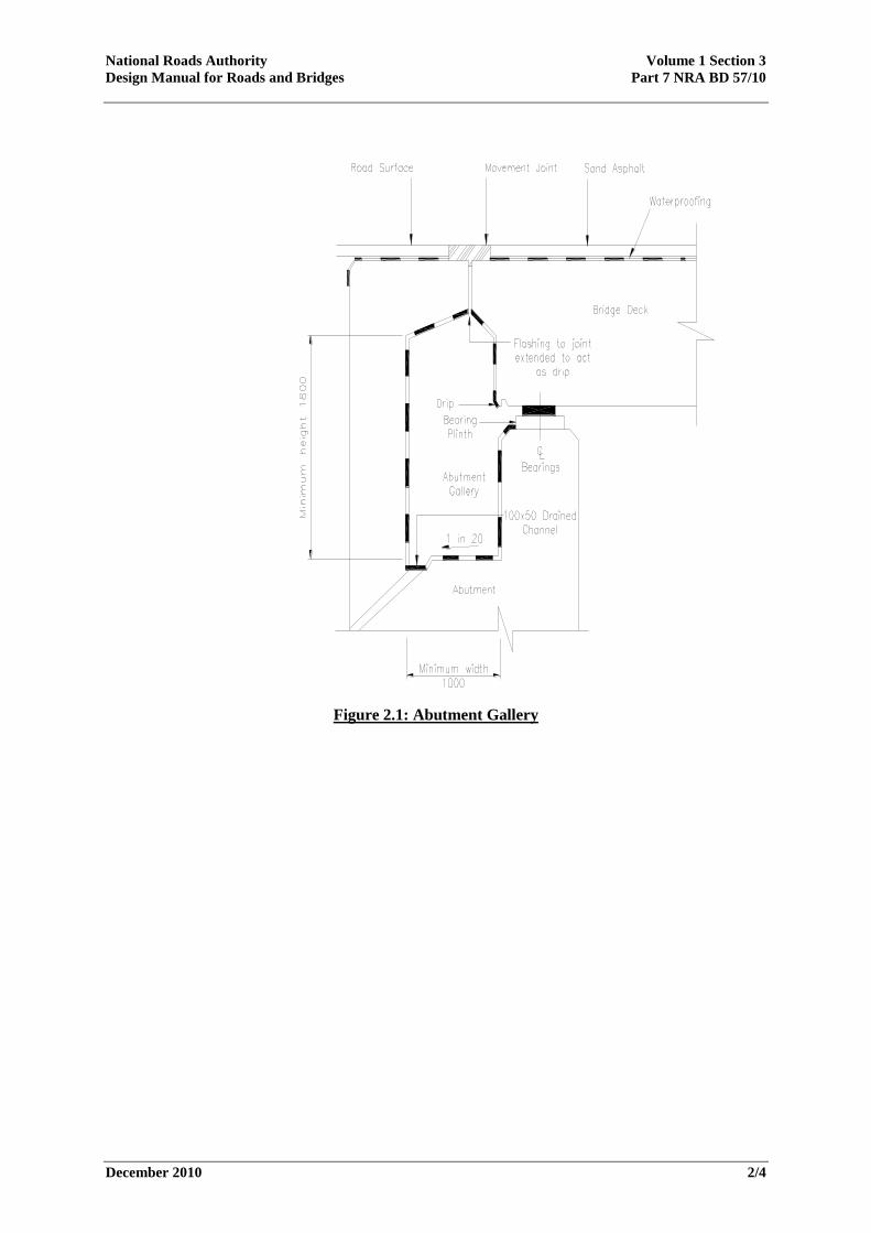
2.21 All bridges which are fully articulated
(ref section 2.4) and / or which use in situ post-
tensioned construction for the deck shall be
provided with abutment galleries of the form
illustrated in Figure 2.1.
2.22 The design of any such structure shall
not include abutment details which create
inaccessible areas which are vulnerable to
concrete contamination by de-icing salts
through leakage at joints or which are difficult
to inspect and maintain.
Substructures
2.23 Exposed structural steelwork shall not
be permitted for use in the substructure of any
bridge with the exception of corrugated steel
buried structures.
Post-tensioned Structures
2.24 Grouted post-tensioned bridge
Structures shall be designed, executed and
completed in accordance with the latest edition
of Concrete Society Technical Paper No 47
“Durable Grouted Post-Tensioned Bridges”.
2.25 Full scale grout trials, in accordance
with the Specification and Concrete Society
Technical Paper No 47, shall be required prior
to execution of any in-situ post tensioned bridge
and after completion of every fifth post
tensioned structure thereafter. All full-scale
grout trials shall be to the profile of a typical
tendon in each structure and shall be over the
full length of the tendon contained in each such
structure design.
Segmental Construction
2.26 Precast concrete segmental construction
shall use external post-tensioning systems.
Segmental construction using internal grouted
tendons shall not be accepted. Where it is
considered by the Design Organisation that this
form of construction is required, this shall
require a Departure from Standards.. .
Cable Replacement
2.27 Structures containing cable stays or
unbonded prestressing strands shall be designed
and detailed to facilitate cable or strand
replacement.
National Roads Authority Volume 1 Section 3
Design Manual for Roads and Bridges Part 7 NRA BD 57/10
December 2010 2/4
Figure 2.1: Abutment Gallery
National Roads Authority Volume 1 Section 3
Design Manual for Roads and Bridges Part 7 NRA BD 57/10
December 2010 3/1
3. IMPROVED DURABILITY – DETAILED
DESIGN STAGE General
3.1 The life of a bridge can be considerably
enhanced at little additional expense by sound
detailing of structural elements. This chapter
gives minimum requirements on aspects of
detailed design, which are known to enhance
durability. For guidance on proven details,
Design Organisations are referred to the CIRIA
Report C543 “Bridge Detailing Guide” (Soubry,
2001).
Reinforcement Cover
3.2 The nominal concrete cover (cnom) to be
specified on the drawings is defined in IS EN
1992-1-1 as the sum of the minimum cover
(cmin) and an allowance for deviation (Δcdev).
Notwithstanding any information to the contrary
in IS EN 1992 or IS EN 206-1 or their
respective national annexes, the minimum cover
for durability to reinforcement in concrete
structures (cmin,dur) shall be in accordance with
the requirements set out in Table B.1 in
Appendix B to this standard.
3.3 The appropriate concrete exposure class
to use on national roads structures shall be in
accordance with Appendix A to this standard,
unless an alternative arrangement has been
agreed with the NRA via the Structures
Technical Acceptance process (see NRA BD02).
3.4 With reference to Figure 2.1, and
notwithstanding any other requirements of this
standard, if circumstances arise which demand a
detail which cannot be waterproofed and cannot
be accessed for maintenance, a minimum
concrete cover to reinforcement of 80mm shall
be provided to those concrete faces directly
below the movement joint.
Drainage
3.5 Systems for the drainage of surface
water from bridges shall be so detailed that
water is not allowed to fall freely from the
bridge deck.
3.6 Openings through bridge decks for
surface water drainage and the routing of
surface water discharge through steel box
sections shall not be permitted.
3.7 Closed drainage systems shall be
sufficiently robust to withstand damage during
cleaning, as this has been an important cause of
problems on many existing bridges. They shall
also be resistant to damage from all commonly
occurring chemical spillages on the road
surface. Drainage systems shall be designed and
detailed so as to accommodate movement of the
structure.
3.8 Drainage waters from bridge decks shall
not be discharged into the drainage layers
behind abutments.
3.9 Drainage systems integral with the
structure, for instance gullies cast into beams
and pipes cast into columns, shall not be used.
On short span bridges surface water shall be
collected off the bridge deck.
3.10 A positive drainage system shall be
provided to all structures to drain any water
percolating through the surfacing and collecting
on the waterproof membrane. The top surface
of all bridge decks shall have adequate falls to
avoid ponding, especially in the vicinity of deck
movement joints.
3.11 Drainage systems shall be provided with
adequate facilities for inspection, rodding and
cleaning operations. Rodding access shall be
provided so that rodding lengths are straight or
virtually straight, and do not normally exceed
45m on straight runs. All gullies shall be fully
trapped. The Design Organisation shall record
the proposed methods of cleaning and
maintaining the proposed drainage systems,
which shall minimise the need for traffic
management, for inclusion in the Safety File. .
National Roads Authority Volume 1 Section 3
Design Manual for Roads and Bridges Part 7 NRA BD 57/10
December 2010 3/2
3.12 All bridge abutments, buried structures
and earth retaining structures shall be provided
with a positive drainage system to the earth
faces in accordance with the NRA Specification
for Road Works. Such drainage systems shall
include for future access and rodding
3.13 Holes shall be provided to drain the
voids of bridge decks (subject to the overriding
requirements of Section 2.17 of this document),
such as box beams and cellular and voided
slabs, as water may find its way into these voids
causing corrosion and deterioration. Box
members shall be provided with sealed access
hatches or manhole covers to prevent leakage
into the box. Adequate and effective ventilation
and drainage holes shall also be provided to
reduce condensation and eliminate any ponding
inside the box as a result of the possible ingress
of water. Ventilation and drainage holes shall
be detailed to prevent access and colonisation by
birds and animals.
3.14 . Bearing shelves and expansion joints
in structures shall be provided with a positive
drainage system tied into the road drainage
system and such drainage systems shall be
accessible for cleaning and rodding.
Drip Checks
3.15 Drip checks shall be provided in the
design for structures at all edge beams, deck
ends over abutments and other locations such as
copings to retaining walls and reinforced earth
bridge abutments and wingwalls to prevent
water running back along horizontal or vertical
surfaces.
3.16 The preferred form of drip check is an
unreinforced concrete downstand. Alternatively,
if a groove type drip check is to be used, the full
cover required by the NRA DMRB measured
from the inside of the groove to the outer most
reinforcement, including links, shall be
provided.
Waterproofing
3.17 Bridge deck waterproofing systems
shall be spray applied, satisfy the requirements
of the NRA Addendum to BD 47 and shall be
capable of being non-destructively tested.
Where waterproofing membranes may be
subject to direct foot traffic, they shall be
sufficiently robust to withstand such use, and
shall not be slippery.
3.18 As a minimum, and notwithstanding any
other requirements, the following surfaces shall
be protected with a bridge deck waterproofing
system complying with section 3.17:
i) The deck slab between parapet upstands.
ii) The parapet upstands to a height of 100
millimetres minimum above adjacent
deck slab level.
iii) The vertical faces at deck ends.
iv) The back of abutment walls for integral
bridges, from bridge deck level to a level
200mm below the construction joint
between superstructure and substructure.
v) All internal faces of service troughs in
bridge decks.
vi) The top face of abutment bearing shelves.
vii) All inaccessible areas which may be at
risk due to leakage.
viii) All internal faces of abutment galleries.
ix) All accessible faces of run on slabs.
3.19 Where buried box sections are to be
used for bridge structures including
accommodation underpasses, the upper surface
of the bottom slab shall be waterproofed with a
bridge deck waterproofing system.
3.20 All exposed concrete in bridge
superstructures, substructures, and box
structures, culverts and retaining walls, shall be
impregnated with a hydrophobic pore liner in
accordance with the NRA Specification for
Road Works except internal faces of culverts
carrying watercourses and drainage.
3.21 All buried concrete faces of structures
not requiring bridge deck waterproofing in
accordance with Sections 3.18 or 3.22, shall be
treated with two coats of epoxy resin
waterproofing for below ground concrete in
accordance with the NRA Specification for
Road Works.
National Roads Authority Volume 1 Section 3
Design Manual for Roads and Bridges Part 7 NRA BD 57/10
December 2010 3/3
3.22 Notwithstanding any other requirements
in the NRA Design Manual for Roads and
Bridges, where buried box sections are to be
used for bridge structures including
accommodation underpasses, the top surface,
and the top of the adjoining vertical external
surfaces to a level of 200mm below the soffit of
the top slab, shall be protected with a suitable
waterproofing system in accordance the
following:
i) Where the depth of cover to the buried
box section is less than 1m (including the
road pavement), the waterproofing system
shall be a proprietary spray applied
system in accordance with the NRA
Addendum to BD 47 and Series 2000 of
the Specification for Road Works.
ii) Where the depth of cover to the buried
box section is greater than 1m and less
than 3m (including the road pavement),
the waterproofing system shall be a
proprietary spray applied system in
accordance with the NRA Addendum to
BD 47 and Series 2000 of the
Specification for Road Works. As an
alternative to this, an approved sheet
membrane waterproofing system may be
used provided that the sheet membrane
system is protected by a nominally
reinforced concrete screed, laid to falls,
and wrapped around the corners of the
buried box section.
iii) Where the depth of cover to the buried
box section is greater than 3m (including
the road pavement), the waterproofing
system shall be a proprietary spray
applied system in accordance with the
NRA Addendum to BD 47 and Series
2000 of the Specification for Road
Works. As an alternative to this, either an
approved sheet membrane waterproofing
system may be used or 2 coats of epoxy
resin waterproofing paint may be used
provided that the sheet membrane system
or the epoxy resin are protected by a
nominally reinforced concrete screed, laid
to falls, and wrapped around the corners
of the buried box section.
Expansion Joints
3.23 The choice of expansion joint for any
particular structure shall be appropriate to the
anticipated level of movement in the structure
and also to the level of traffic to be carried by
the structure. Expansion joints shall be
watertight when installed into any structure and
shall be designed to remain watertight for a
minimum of 10 years following opening of the
structure to traffic.
3.24 Notwithstanding the requirements of
3.23 above, asphaltic plug type expansion joints
shall not be used for structures carrying national
roads or forming part of grade separated
interchanges on national roads.
Structural Steelwork
3.25 Structural steelwork shall be protected
using a paint system appropriate to an Inland or
Marine environment, depending on its location,
and "Difficult" access (all as defined in the
Notes for Guidance to Series 1900 of the
Specification for Road Works), and shall
comply, as a minimum, with all of the following
durability requirements:
i) that no maintenance shall be required
for up to 12 years
ii) that minor maintenance may be required
from 12 years
iii) that major maintenance shall not be
required before 20 years
3.26 The design for structures shall ensure
that steelwork shall be designed and detailed so
as to prevent the accumulation of water, dirt and
debris. Simple connections and weld details,
which are easier to inspect and maintain, shall
be used wherever possible.
3.27 Intermittent fillet welds shall not be
used, except in situations where the welded
connections are completely protected from the
weather, for example, where they are wholly
inside a closed box structure. In such cases
appropriate fatigue checks shall be carried out.
National Roads Authority Volume 1 Section 3
Design Manual for Roads and Bridges Part 7 NRA BD 57/10
December 2010 3/4
3.28 Steel parapets shall be protected by
galvanising only, and shall comply with the
following:
i) galvanising coverage rate shall be in
accordance with EN ISO 1461
ii) stainless steel bolts shall be used for
holding down the parapet and for all other
system fixings.
iii) the finished galvanised surface shall be
smooth and free from sharp projections.
Sealing of Joints
3.29 In the design for structures, other than
drainage culverts, the joint detail between the
pre-cast units for pre-cast concrete units, box
culverts, arches and the like shall contain all of
the following:
i) external surfaces shall be provided with
a continuous 200 millimetres wide strip of
membrane bonded with high quality adhesive
with compressible back up rod;
ii) between units, a continuous hydrophilic
seal with appropriate dimension shall be
provided;
iii) internal surfaces shall be provided with
a continuous two-part polysulphide sealant of
appropriate dimensions.
3.30 In the design for drainage culverts, the
joint detail between pre-cast units for pre-cast
concrete units, box culverts, arches and the like
shall contain all of the following:
i) a continuous preformed compressible
sealing strip between adjacent units and
ii) for internal surfaces, joints shall be
pointed with an elastomeric or bitumen based
sealant
Prestressing
3.31 Post-tensioned structures using external
or unbonded tendons and cable stayed structures
shall be designed and detailed such that
inspection of all individual tendons and their
eventual replacement is possible without
restricting traffic on the road.
3.32 Debonded tendons at the end of precast
pretensioned beams shall be protected against
corrosion.
Mechanical Bearings
3.33 Mechanical bearings where permitted in
the design for structures, shall be either steel
with protection of steelwork against corrosion in
accordance with Series 1900 of the Specification
for Roadworks, or stainless steel with the grades
all as the following:
i) plates and flats shall be 1.4401 or
1.4436 to IS EN 10088
ii) sliding surfaces shall be 1.4436 to IS
EN 10088 and
iii) fasteners shall be A4-70 or A5-80
Voided Slab Construction
3.34 Where the design for structures contains
voided slab construction, the difference in level
of concrete on either side of the void formers
during pouring of the concrete shall be
controlled to avoid movement of the formers
and shall include all of the following:
i) that such difference in level shall not
exceed 150 millimetres and
ii) that provision shall be made for the
compaction of the concrete below the void
formers and for drainage of the formed voids
.
National Roads Authority Volume 1 Section 3
Design Manual for Roads and Bridges Part 7 NRA BD 57/10
December 2010 4/1
4. IMPROVED DURABILITY - MATERIALS General
4.1 The choice of appropriate materials,
which resist the deterioration mechanisms that
most structures are exposed to, can, for a modest
increase in construction cost, significantly
reduce the whole life cost of any structure. This
chapter gives minimum requirements on the
choice of materials which are known to enhance
the durability of structures.
Concrete
4.2 Where structural concrete with steel
reinforcement shall be used in the structures
design, the minimum concrete grade (to IS EN
206) that shall apply to the design for structures
shall comply with all of the following:
i) superstructure concrete - Grade 32/40
ii) footway/verge infill concrete - Grade
25/30
iii) substructure concrete above base level -
Grade 32/40
iv) substructure concrete foundation -
Grade 32/40
v) pre-cast concrete - Grade 40/50
4.3 The maximum water/cement ratio used
in the design for structural concrete with steel
reinforcement shall be in accordance with the
requirements set out in Table B.1 in Appendix B
to this standard.
4.4 The design for all concrete mixes for
buried components shall ensure durability taking
into account the chemical composition of the
soil and groundwater in addition to the stated
strength requirements.
Splash Zone
4.5 The Splash Zone shall be that part of a
bridge or other structure subject to spray from
the adjacent road surface.
4.6 The Splash Zone shall be defined as
follows:
i) the Splash Zone for a structure shall be
the zone extending across the carriageway and
for 8 metres on either side beyond the edge of
the hard shoulder, hard strip or carriageway.
This corresponds to dimension „x‟ in Clause 4.2
of IS EN 1992–2 and the Irish National Annex
to IS EN 1992–2.
ii) the Splash Zone for a structure shall
encompass the bridge deck sides and soffit
where the minimum clearance to the deck soffit
above the carriageway below shall be less than
7.5 metres. This corresponds to dimension „y‟ in
Clause 4.2 of IS EN 1992–2 and the Irish
National Annex to IS EN 1992–2
iii) the Splash Zone for a Structure shall
always include the parapet edge beams of the
bridge Structure
4.7 Within the Splash Zone for a structure
all exposed structural concrete shall be either
air-entrained or shall have a minimum concrete
strength class of C40/50 to IS EN 206.
Additionally, for all exposed concrete within the
Splash Zone one of the following two options
shall be adopted:
(i) concrete shall have a minimum 50
percent ground granulated blast furnace slag and
surface impregnation in accordance with Series
1700 of the Specification for Roadworks with
the exception of precast pre-tensioned pre-
stressed beams of Grade 50/60 concrete or more
to IS EN 206 which shall not be required to have
ground granulated blast furnace slag or
(ii) concrete will be reinforced with type
1.4301 Stainless Steel to IS EN 10088 where the
steel shall be embedded in concrete, otherwise
type 1.4436 Stainless Steel to IS EN 10088.
Stainless Steel Reinforcement
4.8 Where the design for structures contains
run on slabs, stainless steel Type 1.4436 Grade
500 to IS EN 10088 shall be used in connecting
the transition slabs to the abutments.
National Roads Authority Volume 1 Section 3
Design Manual for Roads and Bridges Part 7 NRA BD 57/10
December 2010 4/2
4.9 Notwithstanding any other provisions of
the NRA DMRB, for all structures carrying
national roads or forming part of grade
separated interchanges on national roads,
stainless steel reinforcement Type 1.4301 to IS
EN 10088 shall be used for all reinforcement
within parapet edge beams and below movement
joints on bearing shelves.
4.10 Reinforcement used in the design for
structures to tie parapet edge beams to the
bridge deck shall comply with one of the
following:
i) shall be stainless steel reinforcement
Type 1.4301 to IS EN 10088 or
ii) shall be protected by bridge deck
waterproofing system and the cover to the face
of the parapet edge beam shall be in excess of
80mm.
Weathering Steel
4.11 Where weathering steel shall be used in
the design for structures, the environmental
criteria shall be "severe" as defined in the NRA
Addendum to BD 7.
Fasteners and Anchorages
4.12 Fasteners and anchorages for attachment
to structures shall be stainless steel. Provision
shall be made in the design for structures to
prevent electrolytic corrosion of dissimilar
metals
National Roads Authority Volume 1 Section 3
Design Manual for Roads and Bridges Part 7 NRA BD 57/10
December 2010 5/1
5. DETAILED REQUIREMENTS –
INSPECTION & MAINTENANCE General
5.1 It is vital that the design of structures
includes for general inspection and maintenance
and also for the specific replacement of
elements such as bearings which have a lesser
design life than the overall structure. This
chapter gives minimum requirements to
facilitate the future inspection and maintenance
of structures.
Access - General
5.2 Provision for safe access shall be made
at all structures for all of the following, as
appropriate:
a) routine inspection;
b) cleaning, maintenance and painting;
c) prestressing tendon or stay cable
replacement;
d) inspection within closed cells or box
sections as per Section 2.16;
e) access to parts that may require
maintenance or replacement during the life
of the structure, for instance, bearings,
joints, anchorage locations, drainage, pipes,
manholes, lubrication of moving parts,
lighting systems, etc.;
f) jacking at bearings and for their removal
and replacement;
5.3 Public access to any of the facilities
provided for the use of structure inspection or
maintenance shall be prevented by means of
suitable barriers, covers and the like.
Colonisation of accessible areas by plants,
animals or birds shall be prevented by the
application of suitable measures.
Access & Lighting to Voids
5.4 Subject to the requirements of Sections
2.16 – 2.19, where voided elements of bridge
structures (for example box girder decks, voided
piers, voided abutment stems, inspection
galleries and the like) are of sufficient size to
allow internal inspection, personnel access shall
be provided as per all of the following:
i) For all mainline overbridges, access to
abutment galleries shall be from the minor road
over the bridge. Suitable permanent access
steps shall be provided to facilitate access to
abutment galleries.
ii) access to the voids shall be from the
underside of the bridge
iii) entry points shall be placed in such
positions as to give convenient access, and
where their use would not cause interference to
traffic
iv) all entry points and access ways within
the voids shall be suitably sized and designed to
allow for the evacuation of a casualty, on a
stretcher and the like if necessary
v) specific emergency routes and exits
shall be identified clearly by signs and shall be
provided with lighting where appropriate
vi) entry points to the voids, where
provided, shall be carefully located and detailed
so as to minimise their visibility to passing
traffic
vii) access points to the voids shall not be
permitted on surfaces visible on the main bridge
elevation, with the exception of access doors
and ancillary arrangements for accessing
abutment inspection galleries
viii) all permanent services, equipment and
the like in the Design shall be capable of
withstanding the prevailing environmental
conditions including ingress of dust and water
and the natural movement of the structure
ix) permanent access ladders or steps, as
appropriate, shall be provided at changes in
level within the voids
x) access ladders and steps shall be
provided with guardrails
National Roads Authority Volume 1 Section 3
Design Manual for Roads and Bridges Part 7 NRA BD 57/10
December 2010 5/2
xi) all walking surfaces shall be non-slip,
compatible where appropriate with
waterproofing membranes, shall avoid details
which create a risk of tripping and shall be self-
draining
xii) the interior of fabricated steel box
sections where access shall be required to be
provided in the Design shall be painted a light
colour to improve visibility.
xiii) Where appropriate, a permanent lighting
system with permanent power supply shall be
provided for access routes and access chambers.
5.5 Lighting levels in the design for
structures shall be a minimum of 30 lux.
Additional emergency lighting shall be provided
along emergency routes having a minimum
intensity of 0.2 lux and having a separate battery
operated power supply. Warning notices and
signs shall be provided to all mains power
boards, valves and the like, where their
operation may affect the safety of persons
entering voids within structures.
5.6 All access points to galleries and voids
and the like in the Design for Structures shall be
secured from unauthorized access by means of
lockable steel doors or grills.
Bearing Inspection and Replacement
5.7 Inspection platforms shall be provided
in front of the abutments to overbridges for both
integral and non-integral structures in
accordance with the requirements of CIRIA
C543 „Bridge Detailing Guide‟.
5.8 Where bridge bearings shall be used in
the design of structures they shall be replaceable
without requiring the removal of any structural
concrete or welding of structural steelwork.
5.9 Provision shall be made in the design
for structures to allow for jacking during any
subsequent bearing replacement.
5.10 Provision shall be made in the design
for structures such that no more than one traffic
lane over the structure shall be closed to traffic
during all necessary work to replace bearings.
Services
5.11 Service ducts / pipes (including
drainage pipes) shall not be located on or
adjacent to any external face of a structure. The
attachment of service ducts / pipes (including
drainage pipes) to the exterior of any structure
shall not be permitted.
National Roads Authority Volume 1 Section 3
Design Manual for Roads and Bridges Part 7 NRA BD 57/10
December 2010 6/1
6. REFERENCES
6.1 NRA Design Manual for Roads and Bridges
Volume 1: Highway Structures: Approval Procedures and General Design:
NRA BD 2, Technical Acceptance of Structures on Motorways and Other National Roads (NRA
DMRB 1.1.1A).
Volume 2: Highway Structures: Design (Substructures and Special Structures) Materials:
NRA Addendum to BD 12, Design of Corrugated Steel Buried Structures With Spans Greater
Than 0.9 Metres and up to 8.0 Metres (DMRB 2.2.6)
NRA Addendum to BD 47, Waterproofing and Surfacing of Concrete Bridge Decks (DMRB
2.3.4).
NRA Addendum to BD 7, Weathering Steel for Highway Structures (DMRB 2.3.8).
6.2 National Roads Authority Manual of Contract Documents for Road Works
Volume 1: NRA Specification for Roads Works.
Volume 2: NRA Notes for Guidance on the Specification for Roads Works.
6.3 Irish and British Standards
IS EN 1992-2:2005, Eurocode 2: Design of Concrete Structures. Concrete bridges – design and detailing
rules.
Irish National Annex to IS EN 1992-2:2005, Eurocode 2: Design of Concrete Structures. Concrete bridges
– design and detailing rules.
IS EN 206-1:2002, Concrete – specification, performance, production and conformity
Irish National Annex to IS EN 206-1:2002, Concrete – specification, performance, production and
conformity
IS EN ISO 1461:2009, Hot dip galvanized coatings on fabricated iron and steel articles – specifications
and test methods
IS EN 10088 – 1, Stainless Steel. Part 1, List of Stainless Steels.
6.4 Concrete Society and CIRIA Publications
Soubry, M., 2001. CIRIA Report C543, Bridge Detailing Guide. Construction Industry Research and
Information Association, London.
Technical Report TR47, Durable Bonded Post-Tensioned Concrete Bridges (1996).
National Roads Authority Volume 1 Section 3
Design Manual for Roads and Bridges Part 7 NRA BD 57/10
December 2010 7/1
7. ENQUIRIES
7.1 All technical enquiries or comments on this Standard should be sent in writing to:
Head of Engineering
National Roads Authority
St Martin‟s House
Waterloo Road
Dublin 4
……………………………………
T. AHERN
Head of Engineering

National Roads Authority Volume 1 Section 3
Design Manual for Roads and Bridges Part 7 NRA BD 57/10
December 2010 7/2
National Roads Authority Volume 1 Section 3
Design Manual for Roads and Bridges Part 7 NRA BD 57/10
December 2010 A/1
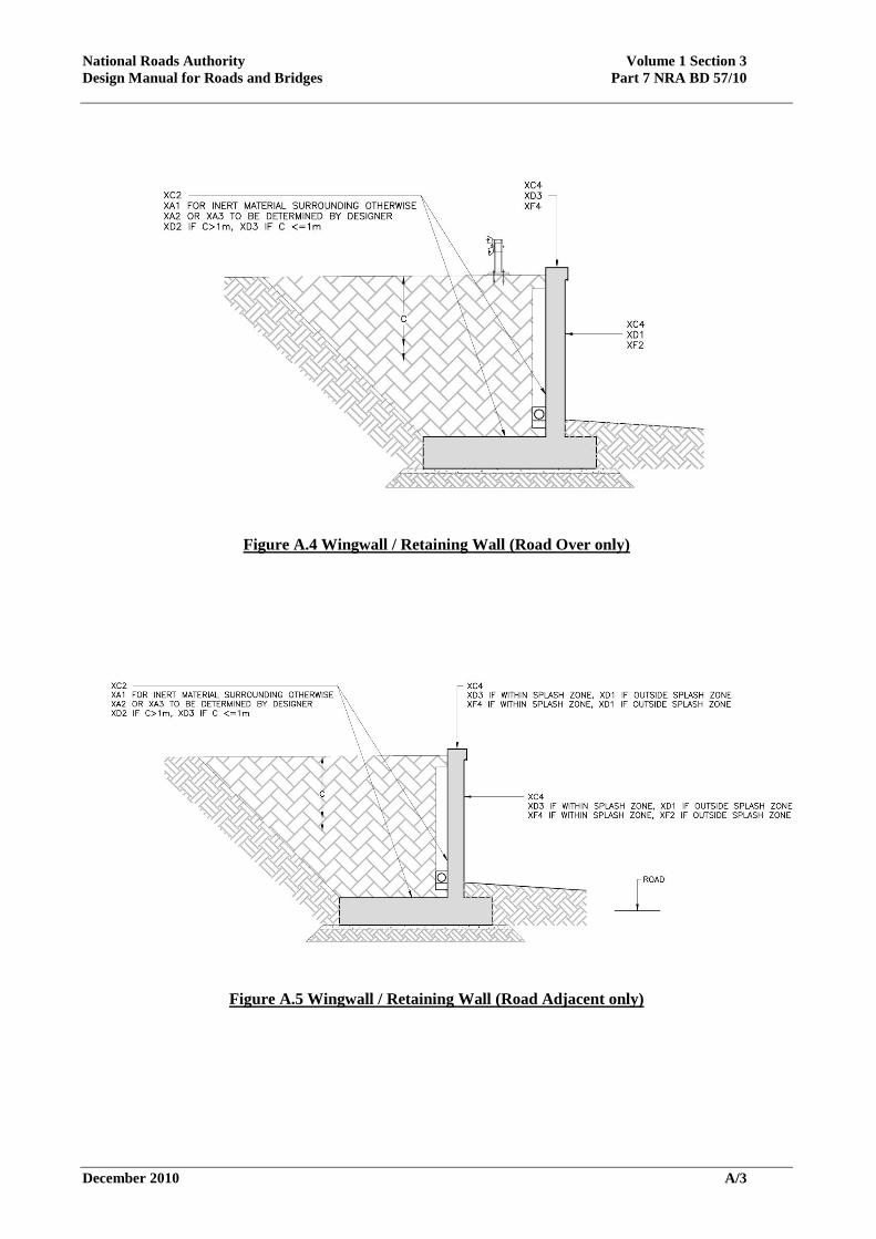
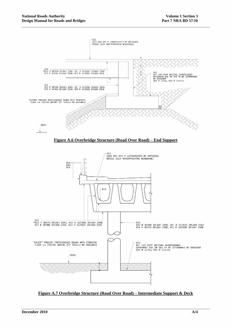
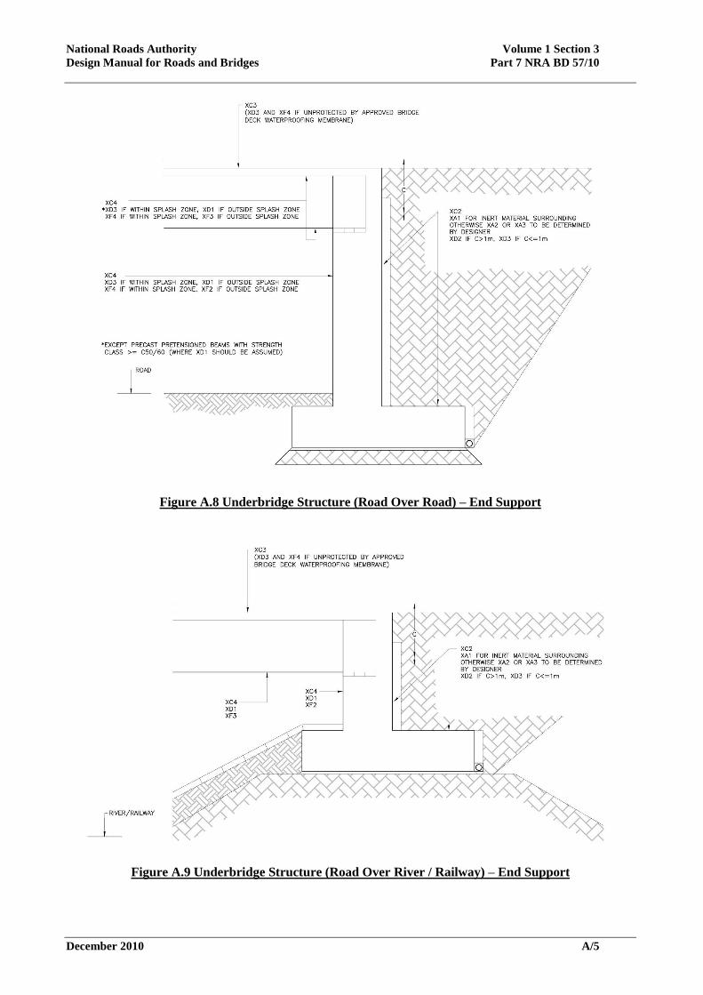
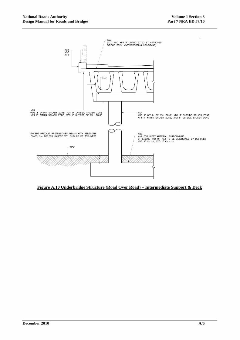
Appendix A – Exposure Class Diagrams
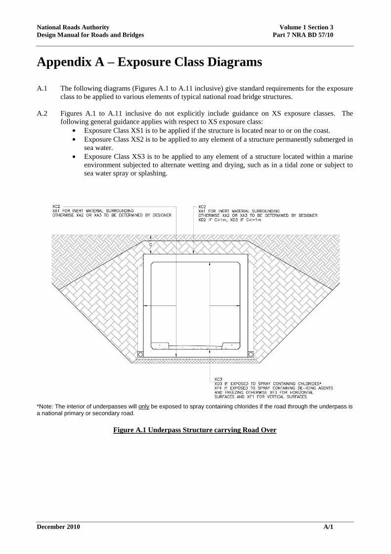
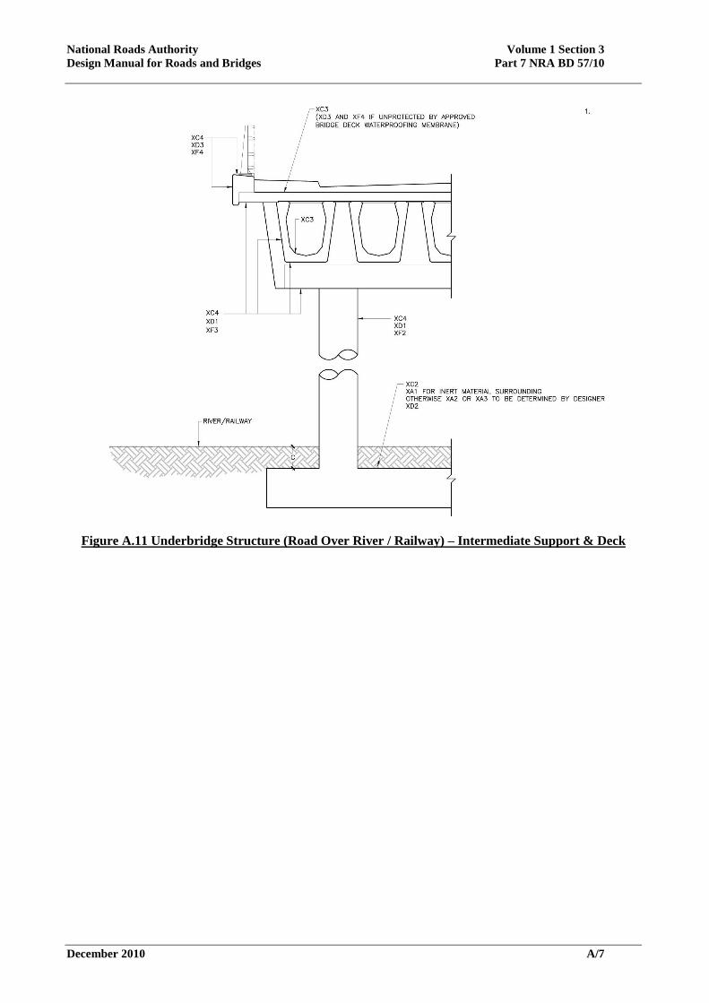
A.1 The following diagrams (Figures A.1 to A.11 inclusive) give standard requirements for the exposure
class to be applied to various elements of typical national road bridge structures.
A.2 Figures A.1 to A.11 inclusive do not explicitly include guidance on XS exposure classes. The
following general guidance applies with respect to XS exposure class:
Exposure Class XS1 is to be applied if the structure is located near to or on the coast.
Exposure Class XS2 is to be applied to any element of a structure permanently submerged in
sea water.
Exposure Class XS3 is to be applied to any element of a structure located within a marine
environment subjected to alternate wetting and drying, such as in a tidal zone or subject to
sea water spray or splashing.
*Note: The interior of underpasses will only be exposed to spray containing chlorides if the road through the underpass is a national primary or secondary road.
Figure A.1 Underpass Structure carrying Road Over
National Roads Authority Volume 1 Section 3
Design Manual for Roads and Bridges Part 7 NRA BD 57/10
December 2010 A/2
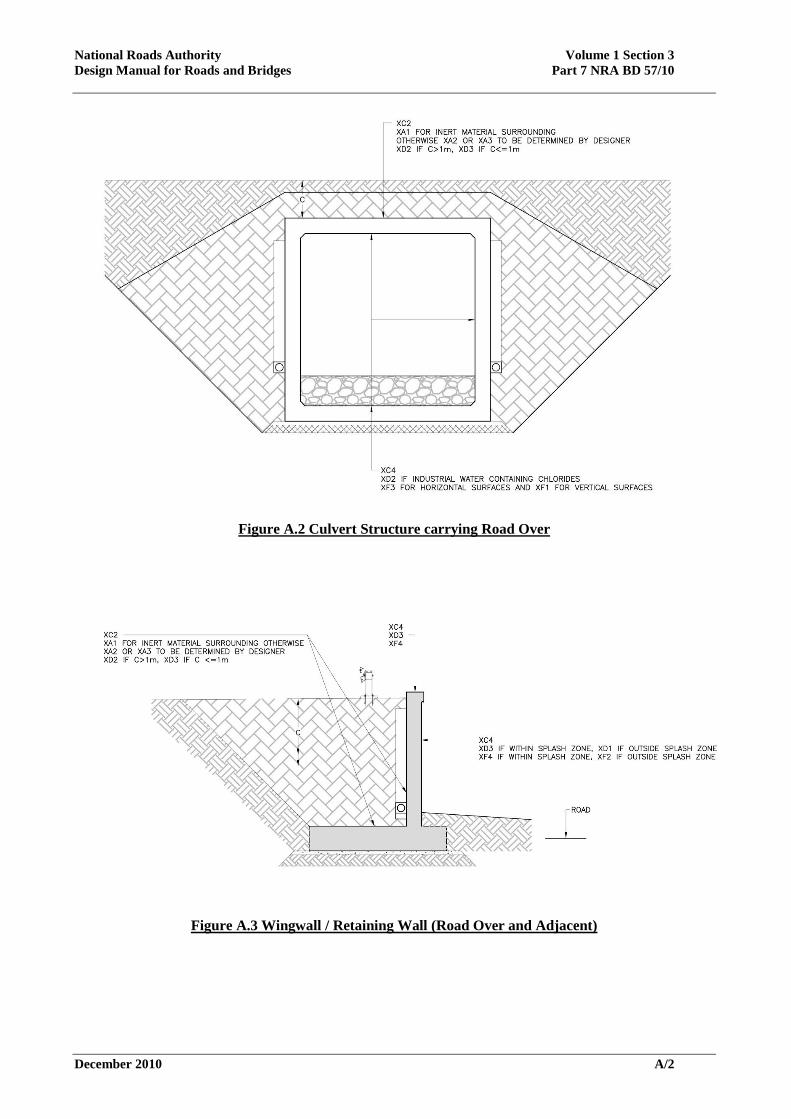
Figure A.2 Culvert Structure carrying Road Over
Figure A.3 Wingwall / Retaining Wall (Road Over and Adjacent)
National Roads Authority Volume 1 Section 3
Design Manual for Roads and Bridges Part 7 NRA BD 57/10
December 2010 A/3
Figure A.4 Wingwall / Retaining Wall (Road Over only)
Figure A.5 Wingwall / Retaining Wall (Road Adjacent only)
National Roads Authority Volume 1 Section 3
Design Manual for Roads and Bridges Part 7 NRA BD 57/10
December 2010 A/4
Figure A.6 Overbridge Structure (Road Over Road) – End Support
Figure A.7 Overbridge Structure (Road Over Road) – Intermediate Support & Deck
National Roads Authority Volume 1 Section 3
Design Manual for Roads and Bridges Part 7 NRA BD 57/10
December 2010 A/5
Figure A.8 Underbridge Structure (Road Over Road) – End Support
Figure A.9 Underbridge Structure (Road Over River / Railway) – End Support
National Roads Authority Volume 1 Section 3
Design Manual for Roads and Bridges Part 7 NRA BD 57/10
December 2010 A/6
Figure A.10 Underbridge Structure (Road Over Road) – Intermediate Support & Deck
National Roads Authority Volume 1 Section 3
Design Manual for Roads and Bridges Part 7 NRA BD 57/10
December 2010 A/7
Figure A.11 Underbridge Structure (Road Over River / Railway) – Intermediate Support & Deck

National Roads Authority Volume 1 Section 3
Design Manual for Roads and Bridges Part 7 NRA BD 57/10
December 2010 A/8
National Roads Authority Volume 1 Section 3
Design Manual for Roads and Bridges Part 7 NRA BD 57/10
December 2010 B/1
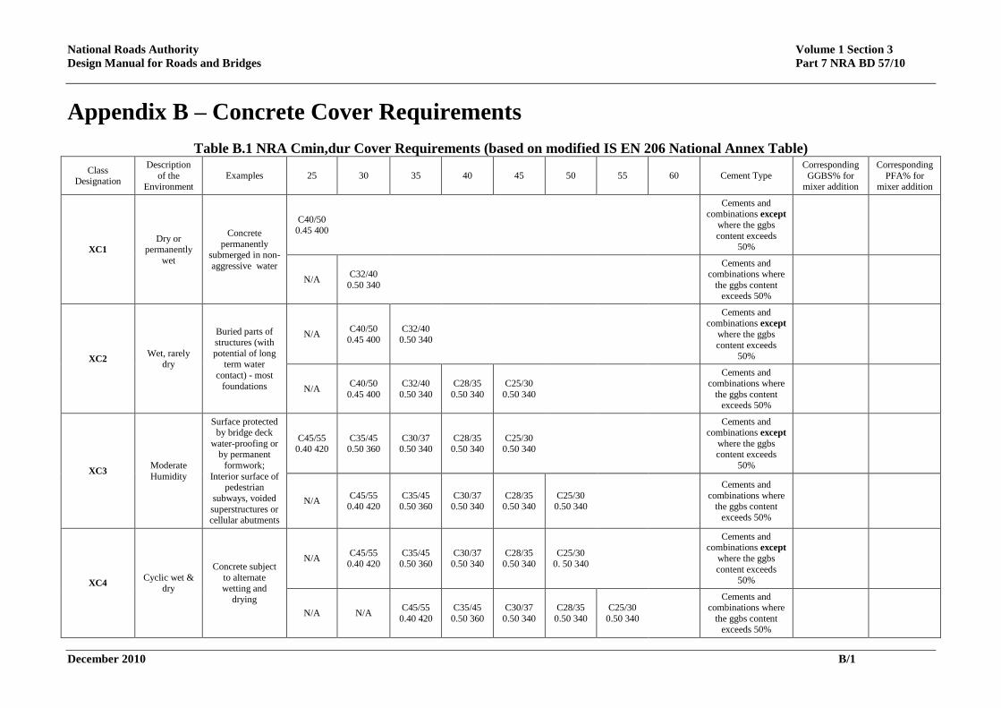
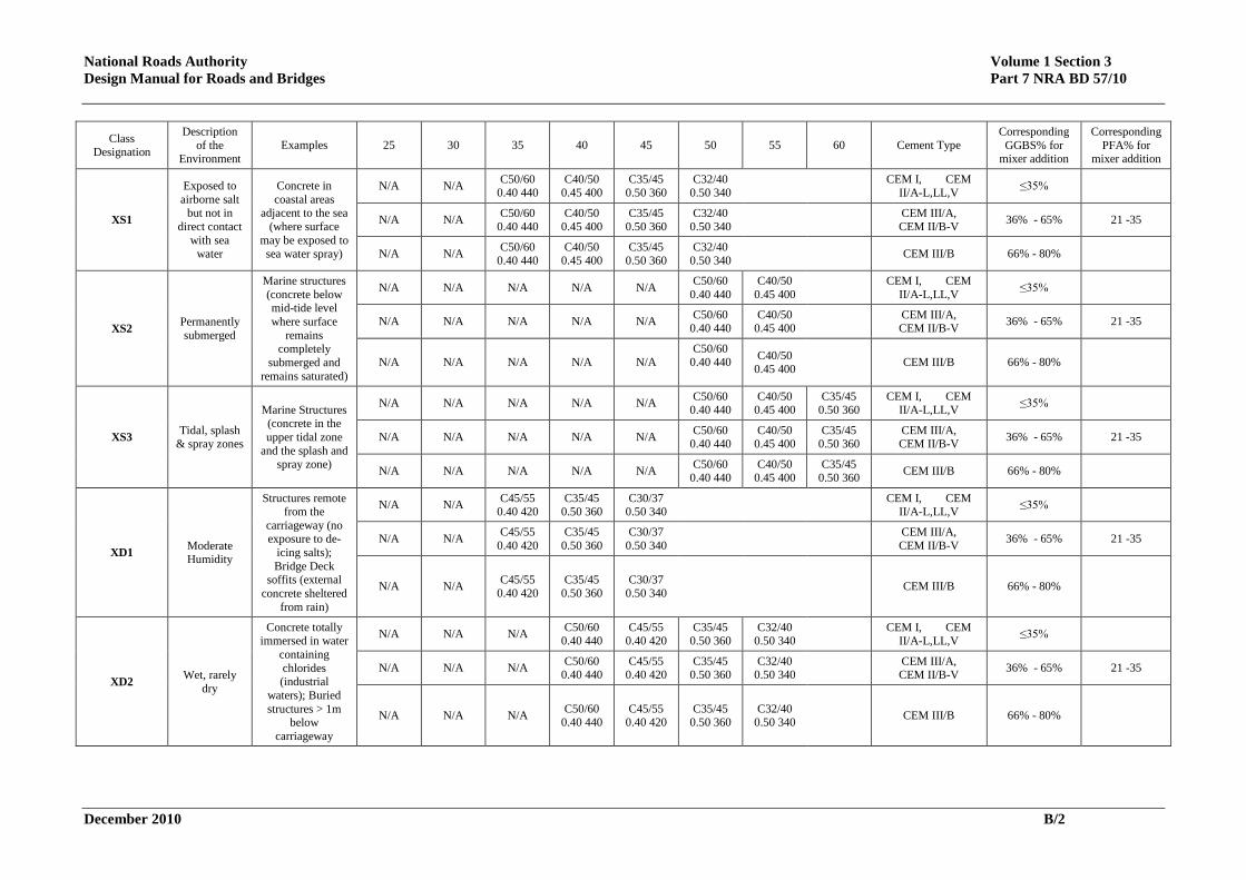
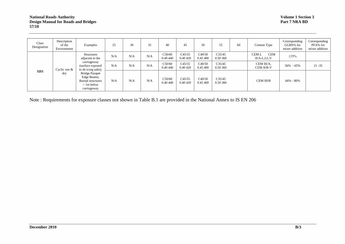
Appendix B – Concrete Cover Requirements
Table B.1 NRA Cmin,dur Cover Requirements (based on modified IS EN 206 National Annex Table)
Class Designation
Description
of the Environment
Examples 25 30 35 40 45 50 55 60 Cement Type Corresponding
GGBS% for mixer addition
Corresponding
PFA% for mixer addition
XC1 Dry or
permanently
wet
Concrete
permanently submerged in non-
aggressive water
C40/50 0.45 400
Cements and combinations except
where the ggbs
content exceeds 50%
N/A C32/40
0.50 340
Cements and combinations where
the ggbs content exceeds 50%
XC2 Wet, rarely
dry
Buried parts of
structures (with
potential of long term water
contact) - most
foundations
N/A C40/50
0.45 400
C32/40
0.50 340
Cements and combinations except
where the ggbs
content exceeds 50%
N/A C40/50
0.45 400
C32/40
0.50 340
C28/35
0.50 340
C25/30
0.50 340
Cements and combinations where
the ggbs content exceeds 50%
XC3 Moderate
Humidity
Surface protected by bridge deck
water-proofing or by permanent
formwork;
Interior surface of pedestrian
subways, voided
superstructures or cellular abutments
C45/55 0.40 420
C35/45 0.50 360
C30/37 0.50 340
C28/35 0.50 340
C25/30 0.50 340
Cements and combinations except
where the ggbs content exceeds
50%
N/A C45/55
0.40 420 C35/45
0.50 360 C30/37
0.50 340 C28/35
0.50 340 C25/30
0.50 340
Cements and
combinations where the ggbs content
exceeds 50%
XC4 Cyclic wet &
dry
Concrete subject
to alternate wetting and
drying
N/A C45/55
0.40 420 C35/45
0.50 360 C30/37
0.50 340 C28/35
0.50 340 C25/30
0. 50 340
Cements and combinations except
where the ggbs
content exceeds 50%
N/A N/A C45/55
0.40 420
C35/45
0.50 360
C30/37
0.50 340
C28/35
0.50 340
C25/30
0.50 340
Cements and combinations where
the ggbs content exceeds 50%
National Roads Authority Volume 1 Section 3
Design Manual for Roads and Bridges Part 7 NRA BD 57/10
December 2010 B/2
Class Designation
Description
of the Environment
Examples 25 30 35 40 45 50 55 60 Cement Type Corresponding
GGBS% for mixer addition
Corresponding
PFA% for mixer addition
XS1
Exposed to
airborne salt but not in
direct contact
with sea
water
Concrete in
coastal areas adjacent to the sea
(where surface
may be exposed to
sea water spray)
N/A N/A C50/60
0.40 440 C40/50
0.45 400 C35/45
0.50 360 C32/40
0.50 340
CEM I, CEM II/A-L,LL,V
≤35%
N/A N/A C50/60
0.40 440 C40/50
0.45 400 C35/45
0.50 360 C32/40
0.50 340
CEM III/A, CEM II/B-V
36% - 65% 21 -35
N/A N/A C50/60
0.40 440
C40/50
0.45 400
C35/45
0.50 360
C32/40
0.50 340 CEM III/B 66% - 80%
XS2 Permanently
submerged
Marine structures
(concrete below mid-tide level
where surface
remains completely
submerged and
remains saturated)
N/A N/A N/A N/A N/A C50/60
0.40 440
C40/50
0.45 400
CEM I, CEM
II/A-L,LL,V ≤35%
N/A N/A N/A N/A N/A C50/60
0.40 440 C40/50
0.45 400
CEM III/A, CEM II/B-V
36% - 65% 21 -35
N/A N/A N/A N/A N/A C50/60
0.40 440 C40/50
0.45 400 CEM III/B 66% - 80%
XS3 Tidal, splash
& spray zones
Marine Structures
(concrete in the
upper tidal zone
and the splash and spray zone)
N/A N/A N/A N/A N/A C50/60
0.40 440 C40/50
0.45 400 C35/45
0.50 360 CEM I, CEM
II/A-L,LL,V ≤35%
N/A N/A N/A N/A N/A C50/60
0.40 440 C40/50
0.45 400 C35/45
0.50 360 CEM III/A, CEM II/B-V
36% - 65% 21 -35
N/A N/A N/A N/A N/A C50/60
0.40 440 C40/50
0.45 400 C35/45
0.50 360 CEM III/B 66% - 80%
XD1 Moderate Humidity
Structures remote from the
carriageway (no exposure to de-
icing salts);
Bridge Deck soffits (external
concrete sheltered
from rain)
N/A N/A C45/55
0.40 420 C35/45
0.50 360 C30/37
0.50 340
CEM I, CEM II/A-L,LL,V
≤35%
N/A N/A C45/55
0.40 420
C35/45
0.50 360
C30/37
0.50 340
CEM III/A,
CEM II/B-V 36% - 65% 21 -35
N/A N/A C45/55
0.40 420
C35/45
0.50 360
C30/37
0.50 340 CEM III/B 66% - 80%
XD2 Wet, rarely
dry
Concrete totally immersed in water
containing
chlorides (industrial
waters); Buried
structures > 1m below
carriageway
N/A N/A N/A C50/60
0.40 440 C45/55
0.40 420 C35/45
0.50 360 C32/40
0.50 340
CEM I, CEM II/A-L,LL,V
≤35%
N/A N/A N/A C50/60
0.40 440 C45/55
0.40 420 C35/45
0.50 360 C32/40
0.50 340
CEM III/A, CEM II/B-V
36% - 65% 21 -35
N/A N/A N/A C50/60
0.40 440 C45/55
0.40 420 C35/45
0.50 360 C32/40
0.50 340 CEM III/B 66% - 80%
National Roads Authority Volume 1 Section 3
Design Manual for Roads and Bridges Part 7 NRA BD
57/10
December 2010 B/3
Class Designation
Description
of the Environment
Examples 25 30 35 40 45 50 55 60 Cement Type Corresponding
GGBS% for mixer addition
Corresponding
PFA% for mixer addition
XD3 Cyclic wet &
dry
Structures adjacent to the
carriageway (surface exposed
to de-icing salts);
Bridge Parapet Edge Beams;
Buried structures
< 1m below carriageway
N/A N/A N/A C50/60
0.40 440 C45/55
0.40 420 C40/50
0.45 400 C35/45
0.50 360
CEM I, CEM II/A-L,LL,V
≤35%
N/A N/A N/A C50/60
0.40 440 C45/55
0.40 420 C40/50
0.45 400 C35/45
0.50 360
CEM III/A, CEM II/B-V
36% - 65% 21 -35
N/A N/A N/A C50/60
0.40 440 C45/55
0.40 420 C40/50
0.45 400 C35/45
0.50 360 CEM III/B 66% - 80%
Note : Requirements for exposure classes not shown in Table B.1 are provided in the National Annex to IS EN 206

Ionad Ghnó Gheata na
Páirce,
Stráid Gheata na Páirce, Baile Átha Cliath 8, Éire
www.tii.ie
+353 (01) 646 3600
Parkgate Business Centre,
Parkgate Street,
Dublin 8, Ireland
+353 (01) 646 3601