Embed Size (px)
Citation preview
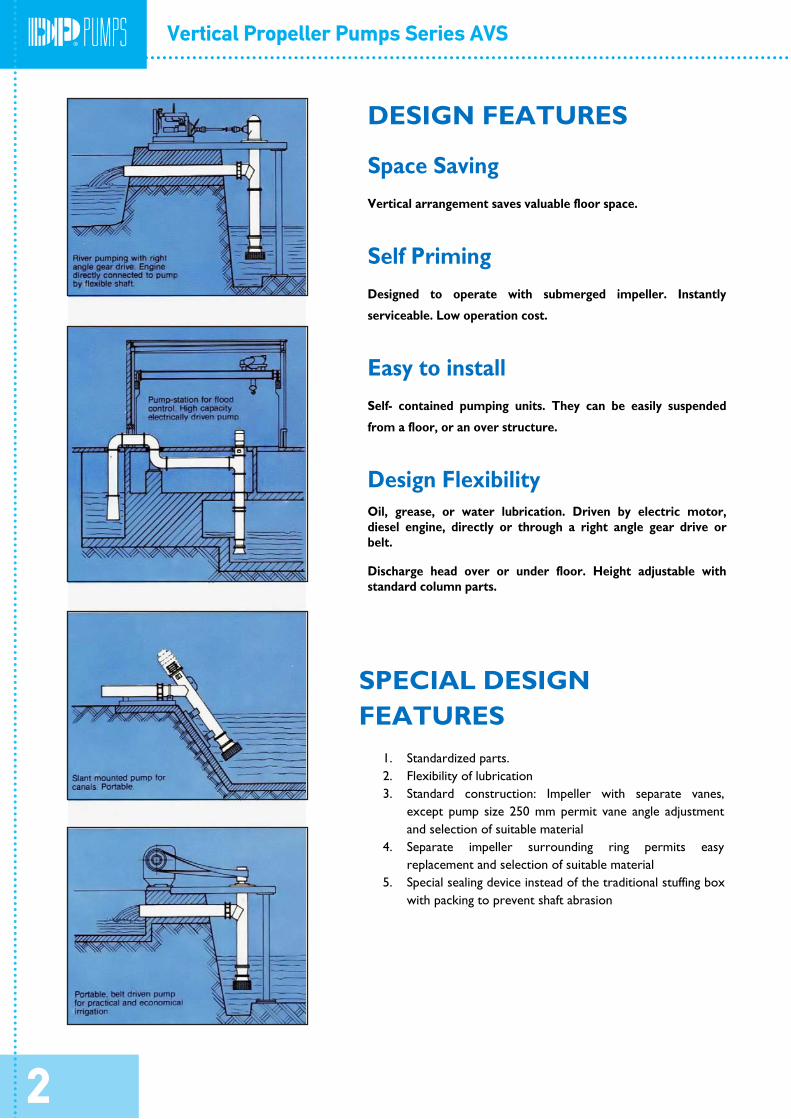
DESIGN FEATURES
Space Saving
Vertical arrangement saves valuable floor space.
Self Priming
Designed to operate with submerged impeller. Instantly
serviceable. Low operation cost.
Easy to install
Self- contained pumping units. They can be easily suspended
from a floor, or an over structure.
Design Flexibility
Oil, grease, or water lubrication. Driven by electric motor, diesel engine, directly or through a right angle gear drive or belt.
Discharge head over or under floor. Height adjustable with standard column parts.
SPECIAL DESIGN FEATURES
1. Standardized parts. 2. Flexibility of lubrication 3. Standard construction: Impeller with separate vanes,
except pump size 250 mm permit vane angle adjustment and selection of suitable material
4. Separate impeller surrounding ring permits easy
replacement and selection of suitable material 5. Special sealing device instead of the traditional stuffing box
with packing to prevent shaft abrasion
2
Smaller elbows and column are made from standard weight pipe. They are machined between centers for perfect alignment and concentricity. On lengths exceeding 12 feet the column is furnished separately. All joints between bowl assembly , column and elbow are fitted with machined and registered steel flanges.
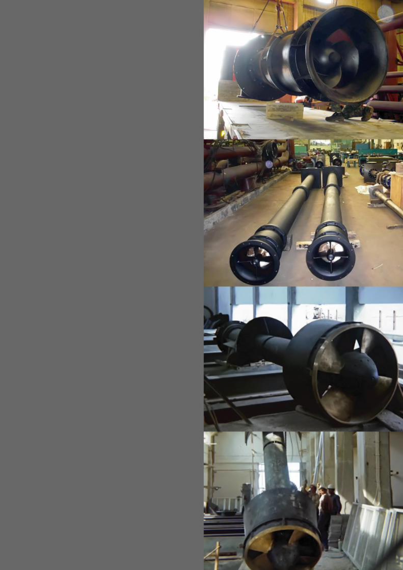
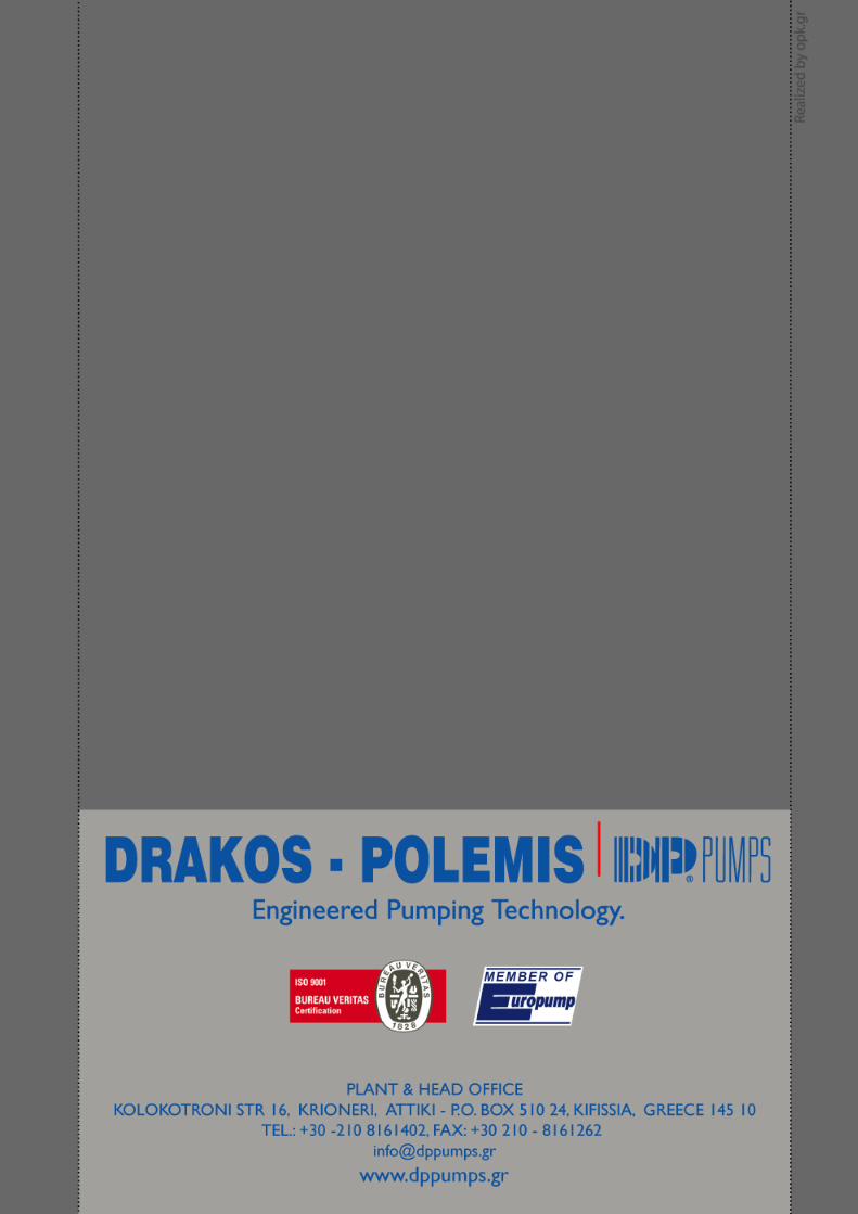
GENERAL
The AV type pumps are propeller axial flow pumps. Capacity from 300 to 25000 m3/h. Total heads up to 10 m per stage. Usually the propeller pumps are installed in a vertical position taking suction from an open sump discharging through a 90 degree elbow. They can be mounted horizontally if necessary. It is also quite common to lay the pump at on angle on a level or ditch bank. This reduces the cost of the supporting structure.
DRIVER SHAFT ASSEMBLY
The drive shaft is made of carbon steel for oil lubricated and of
stainless steel or of carbon steel with sleeves for water or grease lubricated and of rubber for water lubricated pumps. They are spaced at a length such that the operating speed will not be more than 80% of the first critical speed.
DRIVERS
Electric Motors
Electric motors, are, usually connected directly to the pump. With hollow shaft motors, downward thrust of the pumps’ rotating assembly is carried by a thrust bearing built into the motor. The line shaft extends up through the motor shaft and is properly secured at the top. With solid shaft motors, the line shaft is connected to a heavy ball bearing thrust assembly, located on the pump base plate.
BOWL ASSEMBLY The bowl assembly consists of a type 416 stainless steel pump shaft, cast iron bowl and suction bell, SAE 660 bronze bearings for oil or grease lubrication and rubber for water lubrication. Impeller with separate adjustable flanged vanes or bronze SAE 40 and impeller hub of cast iron, except for the pump sizes up to 250 which have one-piece impellers of bronze SAE 40. Type 416 S.S. thrust collar and propeller key. The suction bell is flared and has guide vanes to prevent prerotation and inhibit the formation of vortices in the sump.
Internal Combustion Engines
The drivers are connected to the pump by a right angle gear drive or through a belt drive. Diffusion vanes in the discharge bowl guide the water upward and
convert the velocity to pressure head. The propellers in all size pumps are mounted on the shaft with a split thrust collar. This allows the propellers to be removed from the bottom of the pump simply by taking off the suction bell and dropping the shaft.
PUMP ELBOW
AND SUPPORTING
The suction bearing is protected by a sand collar. Also the discharge bearing of the water or grease lubricated pumps. COLUMN
The elbow and column support the driver and guide the flow of the water from the bowl assembly to the discharge piping. The elbow is integral with the baseplate and can be either above or below it , depending on the requirements of the installation. The below base elbow is usually preferred as its lower center of gravity makes for a more stable pump and motor assembly. The above base, or surface elbow sometimes allows the use of a smaller supporting structure. Normally the elbow discharge is horizontal, or at 90 degrees from the pump shaft, but other angles can be furnished if required. The end of the elbow is round and plain, to accommodate a flexible pipe coupling similar to the Dresser Style 38.
LUBRICATION
Oil Lubrication All line shaft bearings are oil lubricated from oiler on the motor base. Oiler can be hand operated or solenoid for automatic lubrication. The bottom pump bearing is packed with water resistant grease, securing a long period of operation
A flanged elbow can be furnished but some degree of flexibility should be provided as large discharge pipe can seldom se set perfectly true. The standard elbow is made with one 45 degree section to direct the flow from vertical to horizontal. Elbows with guide vanes or long sweep elbows with five intermediate sections can also be furnished. Both the one section elbow and the vane type have a loss coefficient of 0.5. The five section elbow has a loss coefficient of about 0.25 provided that R/D is at least 1.5 . The vane type elbow is not recommended since the loss coefficient is no better and the vanes can easily clog. The five –section elbow requires more space but should be used if efficiency is important
Grease Lubrication Bronze line shaft bearings are lubricated by a grease pump, on the motor base.
Water Lubrication The line shaft bearings are made of rubber and are water lubricated. The suction bowl bearing is grease lubricated. This type is recommended for clear water to avoid oil contamination. The pump should not be dry, as the rubber bearings will seize.
The large elbows and column are rolled and fabricated from mild steel plate and electric welded
For turbid water we can also use enclosed line shaft and lubrication with clean water from an external source
3
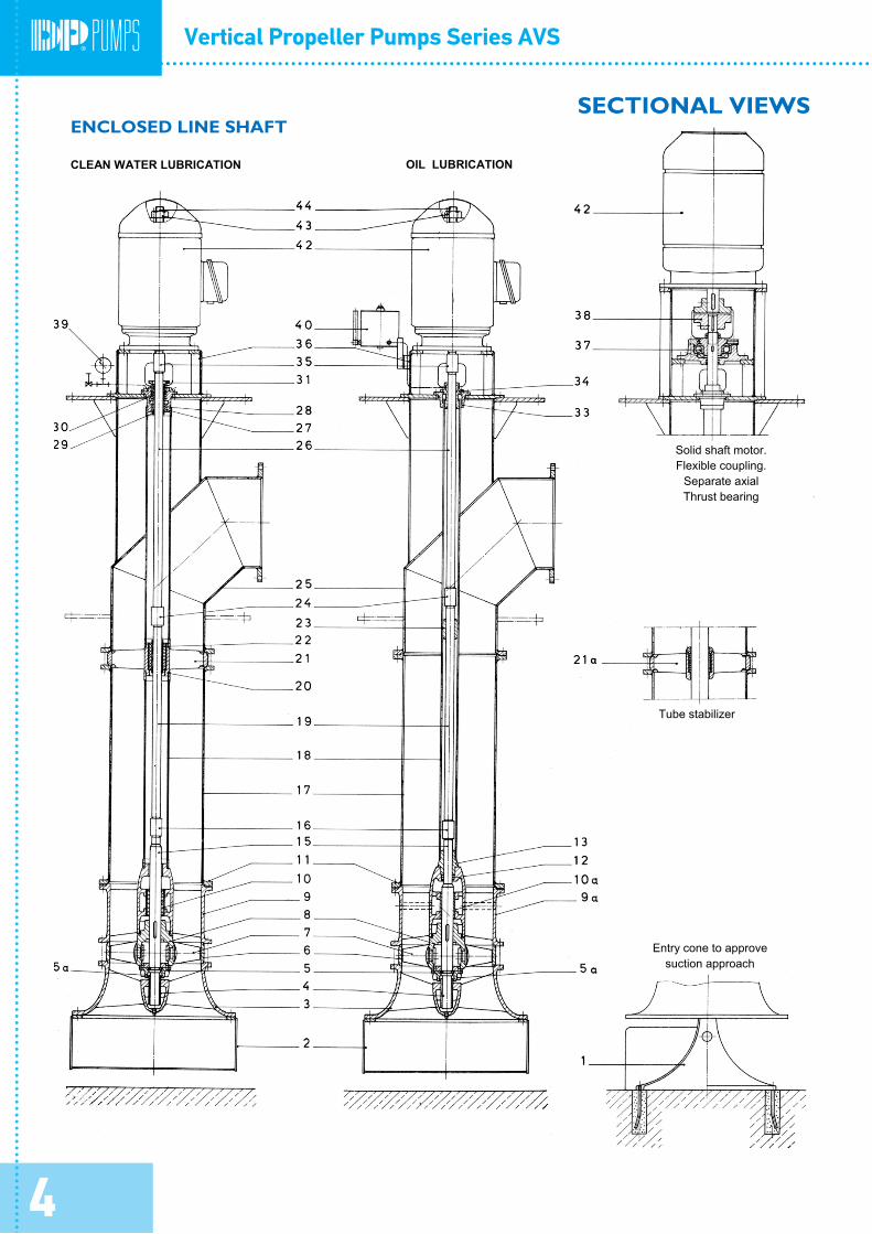
SECTIONAL VIEWS
E NCLOSED LINE SHAFT
CLEAN WATER LUBRICATION OIL LUBRICATION
Solid shaft motor.
Flexible coupling. Separate axial Thrust bearing
Tube stabilizer
Entry cone to approve suction approach
4
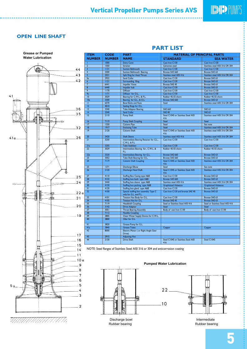
PART LIST MATERIAL OF PRINCIPAL PARTS ITEM
NUMBER CODE NUMBER
PART NAME STANDARD SEA WATER
1 1000 Entry Cone Cast Iron C130 Cast Iron C130 2 1050 Strainer Galvanize steel Stainless steel AISI 316 OR 304 3 1131 Suction Bellmouth Cast Iron C130 Cast Iron C130 4 3300 Suction Bellmouth Bearing Bronze SAE 660 Bronze SAE 63 5 2531 Split Ring for Axial Thrust Stainless steel AISI 416 Stainless steel AISI 316 OR 304 5a 2922 Sand Collar Cast Iron C130 Bronze SAE 63 6 1121 Surrounding Ring Cast Iron C130 Bronze SAE 63 7 6441 Impeller Vanes Bronze SAE 40 Bronze SAE 63 8 6440 Impeller hub Cast Iron C130 Bronze SAE 63 9 1170 Diffuser Cast Iron C130 Cast Iron C130 9a 1171 Diffuser for O.L. Cast Iron C130 Cast Iron C130 10 3029 Bearing for C.W.L. & P.L. Rubber 45-55 shore Rubber 45-55 shore 10a 3300 Bearing for G.L., & O.L. Bronze SAE 660 Bronze SAE 63 11 6570 Bowl Bolts and Nuts Steel Stainless steel AISI 316 OR 304 12 4010 Sealing Rings for O.L. 13 3340 Tube Adaptor Bearing SAE 660 SAE 63 14 2540 Sand Collar SAE 40 SAE 63 15 2110 Pump Shaft Steel C1045 or Stainless Steel AISI
416 Stainless steel AISI 316 OR 304
16 7119 Pump Shaft Coupling Steel Steel 17 1350 Column Pipe Steel See note 18 1917 Enclosing Tube Steel Stainless steel AISI 316 OR 304 19 2120 Column Shaft Steel C1045 or Stainless Steel AISI
416 Stainless steel AISI 316 OR 304
20 3420 Shaft Sleeve Stainless steel AISI 416 Stainless steel AISI 316 OR 304 21 3250 Intermediate Bearing Retainer for G.L.,
C.W.L. & P.L Cast Iron C130 Cast Iron C130
21a 3255 Tube Stabilizer Cast Iron C130 Cast Iron C130 22 3029 Intermediate Bearing for., C.W.L. &
P.L Rubber 45-55 shore Rubber 45-55 shore
22a 3320 Intermediate Bearing for G.L. Bronze SAE 660 Bronze SAE 63 23 3052 Tube Shaft Bearing for O.L. Bronze SAE 660 Bronze SAE 63 24 7119 Column Shaft Coupling Steel C1045 or Stainless Steel AISI
416 Stainless steel AISI 316 OR 304
25 1371 Discharge Elbow Steel See note 26 2120 Discharge Head Shaft Steel C1045 or Stainless Steel AISI
416 Stainless steel AISI 316 OR 304
27 4110 Stuffing Box Casing type A&B Cast Iron C130 Bronze SAE 63 28 4132 Stuffing box bush type A&B Bronze SAE 660 Bronze SAE 63 29 3440 Stuffing box sleeve type A&B Stainless steel AISI 416 Stainless steel AISI 316 OR 304 30 4130 Stuffing box packing type A&B Graphitized Asbestos Graphitized Asbestos 31 4120 Stuffing box gland type A&B Cast Iron C130 Bronze SAE 63 32 4100 Special stuffing box assembly Type C
only for G.L. and P.L. Cast Iron C130 and bronze SAE 40 Bronze SAE 63
33 4101 Tension Nut Body for O.L. Cast Iron C130 Bronze SAE 63 34 4105 Tension Nut for O.L. Bronze SAE 40 Bronze SAE 63 35 7119 Headshaft Coupling Steel or Stainless Steel AISI 416 Steel or Stainless Steel AISI 416 36 3142 Drive Adaptor Steel Steel 37 3051 Thrust Bearing Assembly Body of cast Iron C130 Body of cast Iron C130 38 7112 Flexible Coupling 39 3805 Clean Water Supply Device for C.W.L. 40 3800 Oiler for O.L.
41 3820 Grease Pump for G.L. 41a 3840 Grease Tubes Copper Copper 42 8000 Electric Motor ( or Right Angle Gear
Drive)
43 2915 Adjusting Nut 44 2130 Drive Shaft Steel C1045 or Stainless Steel AISI
416 Steel C1045
NOTE: Steel flanges of Stainless Steel AISI 316 or 304 and anticorrosion coating
OPEN LINE SHAFT
Pumped Water Lubrication
Discharge bowl Rubber bearing
Intermediate Rubber bearing
Grease or Pumped Water Lubrication
5
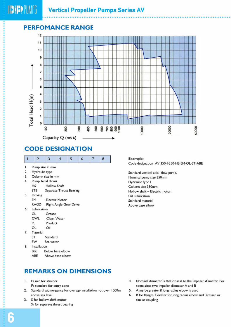
PERFOMANCE RANGE
Tot
al H
ead
H(m
)
Capacity Q (m3/ h)
CODE DESIGNATION
1 2 3 4 5 6 7 8 Example: Code designation AVS 350-I-350-HS-EM-OL-ST-ABE
1. Pump size in mm 2. Hydraulic type Standard vertical axial flow pump. 3. Column size in mm Nominal pump size 350mm 4. Pump Axial thrust Hydraulic type I
HS Hollow Shaft Column size 350mm. STB Separate Thrust Bearing Hollow shaft – Electric motor.
5. Driving Oil Lubrication EM Electric Motor Standard material RAGD Right Angle Gear Drive Above base elbow
6. Lubrication GL Grease CWL Clean Water PL Product OL Oil
7. Material ST Standard SW Sea water
8. Installation BBE Below base elbow ABE Above base elbow
REMARKS ON DIMENSIONS
1. Fs min for strainer 4. Nominal diameter is that closest to the impeller diameter. For some sizes two impeller diameter A and B Fs standard for entry cone
2. Standard submergence for overage installation not over 1000m above sea level
5. A my be greater if long radius elbow is used 6. B for flanges. Greater for long radius elbow and Dresser or
similar coupling 3. SI for hollow shaft motor SII for separate thrust bearing
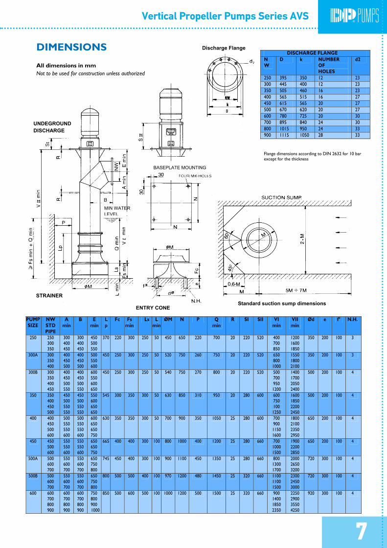
DIMENSIONS
All dimensions in mm Not to be used for construction unless authorized
Discharge Flange
BASEPLATE MOUNTING
UNDEGROUND DISCHARGE
Standard suction sump dimensions ENTRY CONE
STRAINER
MIN WATER LEVEL
DISCHARGE FLANGE NW
D k NUMBER OF HOLES
d2
250 395 350 12 23 300 445 400 12 23 350 505 460 16 23 400 565 515 16 27 450 615 565 20 27 500 670 620 20 27 600 780 725 20 30 700 895 840 24 30 800 1015 950 24 33 900 1115 1050 28 33
Flange dimensions according to DIN 2632 for 10 bar except for the thickness
PUMP SIZE
NW STD PIPE
A min
B E min
Lp
Fc Fs min
Ls L min
ØM N P Q min
R SI SII VI min
VII min
Ød e f° N.H.
250 250 300 350
300 400 450
300 400 450
450 500 550
370 220 300 250 50 450 650 220 700 20 220 520 400 700 850
1200 1600 1850
350 200 100 3
300A 300 350 400
400 450 500
400 450 500
500 550 600
450 250 300 250 50 520 750 260 750 20 220 520 650 800 1000
1550 1800 2100
350 200 100 3
300B 300 350 400 450
400 450 500 550
400 450 500 550
600 550 600 650
450 250 300 250 50 540 750 270 800 20 220 520 500 700 950 1200
1400 1700 2050 2400
500 200 100 4
350 350 400 450 500
450 500 550 550
450 500 550 550
550 600 650 650
545 300 350 300 50 630 850 310 950 20 280 600 600 750 100 1250
1600 1850 2200 2450
500 200 100 4
400 400 450 500 600
500 550 550 600
500 550 550 600
600 650 650 750
630 350 350 300 50 700 900 350 1050 25 280 600 700 900 1150 1600
1800 2100 2350 2950
650 200 100 4
450 450 500 600
550 550 600
550 550 600
650 650 750
665 400 400 300 100 800 1000 400 1200 25 280 660 700 1000 1500
1900 2200 2850
650 200 100 4
500A 500 600 700
550 600 700
550 600 700
650 750 800
745 450 400 300 100 900 1100 450 1350 25 280 660 800 1300 1700
2000 2650 3200
720 300 100 4
500B 500 600 700
550 600 700
550 600 700
650 750 800
800 500 500 400 100 970 1200 480 1450 25 320 660 1100 1100 1500
2300 2450 3000
720 300 100 4
600 600 700 800 900
600 700 800 900
600 700 800 900
750 800 900 1000
850 500 600 500 100 1000 1200 500 1500 25 320 660 900 1400 1850 2350
2250 2900 3550 4250
920 300 100 4
7
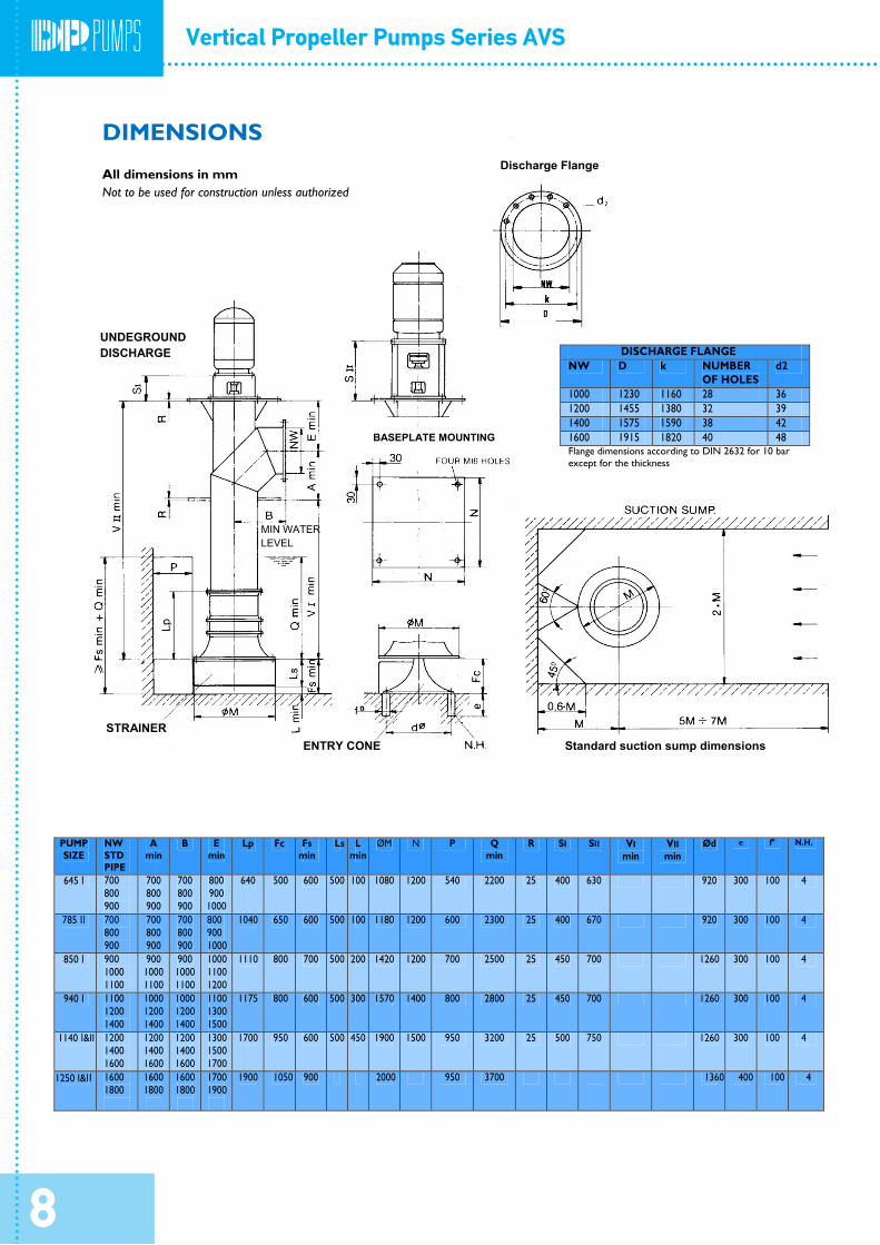
PUMP SIZE
NW STD PIPE
A min
B E min
Lp Fc Fs min
Ls L min
ØM N P Q min
R SI SII VI min
VII min
Ød e f° N.H.
645 Ι 700 800 900
700 800 900
700 800 900
800 900 1000
640 500 600 500 100 1080 1200 540 2200 25 400 630 920 300 100 4
785 ΙΙ 700 800 900
700 800 900
700 800 900
800 900 1000
1040 650 600 500 100 1180 1200 600 2300 25 400 670 920 300 100 4
850 Ι 900 1000 1100
900 1000 1100
900 1000 1100
1000 1100 1200
1110 800 700 500 200 1420 1200 700 2500 25 450 700 1260 300 100 4
940 Ι 1100 1200 1400
1000 1200 1400
1000 1200 1400
1100 1300 1500
1175 800 600 500 300 1570 1400 800 2800 25 450 700 1260 300 100 4
1140 Ι&II 1200 1400 1600
1200 1400 1600
1200 1400 1600
1300 1500 1700
1700 950 600 500 450 1900 1500 950 3200 25 500 750 1260 300 100 4
1250 I&ΙΙ 1600 1800
1600 1800
1600 1800
1700 1900
1900 1050 900 2000 950 3700 1360 400 100 4
DISCHARGE FLANGE NW D k NUMBER
OF HOLES d2
1000 1230 1160 28 36 1200 1455 1380 32 39 1400 1575 1590 38 42 1600 1915 1820 40 48 Flange dimensions according to DIN 2632 for 10 bar except for the thickness
Discharge Flange
DIMENSIONS
All dimensions in mm Not to be used for construction unless authorized
UNDEGROUND DISCHARGE
BASEPLATE MOUNTING
MIN WATER LEVEL
STRAINER ENTRY CONE Standard suction sump dimensions
8