Embed Size (px)
Citation preview

N A S A TECHNICAL NOTE
DESIGN, FABRICATION, AND PRELIMINARY EVALUATION OF THERMAL A N D HYDRAULIC PERFORMANCE OF A PROTOTYPE SNAP-8 MERCURY BOILER
by E d w u r d R. Fzlrmun und David W. Medwid
Lewis Reseurch Center Cleve lmd, Ohio 44135
NATIONAL AERONAUTICS AND SPACE ADMINISTRATION WASHINGTON, D. C. AUGUST 1971 * .,

TECH LIBRARY KAFB, NM
12. Sponsoring Agency Name and Address
._ 2. Government Accession No. I 111111 Ill11 lllll lllll lllll lllll1llll Ill1 Ill - I 0133314 1. Report No.
NASA TN D-6451 4. Title and Subtitle DESIGN. FABRICATION. AND PRELIMINARY i 5. Report Date
Technical Note
EVALUATION OF THERMAL AND.HYI~RAULIC PERFORMANCE I August 1971 6. Performing Organization Code I O F A PROTOTYPE SNAP-8 MERCURY BOILER
19. Security Classif. (of this report)
Unclassified
7. Author(s)
20. Security Classif. (of this page) 21. NO. of Pages 22. Price'
Unclassified 47 $3.00
i 8. Performing Organization Report No.
Edward R. Furman and David W. Medwid I E-6149
9. Performing Organization Name and Address
Lewis Research Center National Aeronautics and Space Administration
11. Contract or Grant No. i
I I 5. Supplementary Notes
16. Abstract
A prototype SNAP-8, tantalum/stainless-steel, double-containment mercury boiler, designated Serial Number 4, was fabricated a t Lewis Research Center and successfully tested in the Power Conversion System loop a t the Aerojet Nuclear Systems Company, Azusa, California, for a total of 1620 hours and 26 thermal cycles. This boiler design embodied the same basic tube- bundle configuration as earlier units but included the following significant improvements: the elimination of the expansion bellows by the use of improved tantalum/stainless- s teel bimetal joints; full coiling for more compactness; and a more uniform shell-side NaK flow distribution. The thermal-hydraulic performance of this boiler fully met the SNAP-8 system requirements.
17. Key Words (Suggested by Author(s) )
louble containment Multitube 3imetal joints VaK-78 Punch point mercury Wetting
Helical tub e geometry
18. Distribution Statement Unclassified - unlimited

DESIGN, FABRICATION, AND PRELIMINARY EVALUATION OF THERMAL AND
HYDRAULIC PERFORMANCE OF A PROiOTYPE SNAP-8 MERCURY BOILER by Edward R. Furman and David W. Medwid
Lewis Research Center
SUMMARY The SNAP-8 (Systems for Nuclear Auxiliary Power) Program has successfully
utilized tantalum as the mercury-containment material in a multitube, counterflow boiler. Four units, which were designed and fabricated at the Lewis Research Center, have been extensively tested in various component and system loops and have accumu- lated over 25 400 hours of operation. The first three of these assemblies w e r e of a common design. The fourth unit, designated Serial Number 4, was redesigned to incor- porate changes which were considered desirable in providing a margin to meet the sys- tem requirements. These changes included the following:
(1) The boiler length was decreased from 11.3 meters (37 f t ) to 7.6 meters (25 f t ) and the inlet plug length was lessened from 132 centimeters (52 in.) to 107 centimeters (42 in.). This optimization of boiler tube and inlet plug lengths, in conjunction with other changes mentioned later, resulted in a savings of 27.6 newtons per square 'centimeter (40 psi) in two-phase pressure drop without any change in overall thermal performance.
(2) Significant changes were made to the heating-fluid flow geometry to improve mixing of the NaK and to reduce the NaK pressure drop from 2 . 4 newtons per square centimeter (3. 5 psi) to 1. 7 newtons per square centimeter (2. 5 psi).
(3) The bellows, which w a s originally included to accommodate the differential thermal expansion between the straight tantalum and stainless-steel tubes at the boiler mercury inlet of the first three boiler assemblies, w a s eliminated, thereby permitting full coiling of the boiler for compactness.
uniform pressure drop.
Serial Number 4 boiler assembly. truded bimetal tube.
(6) The tantalum tube/plug assemblies were coiled as required for boiler compact- ness without excessive local deformation (bulging) of the tube wall at the plug end due to end stiffness affects of the plug.
stainless-steel end flanges without any sign of joint degradation.
SNAP-8 system performance and stability requirements.
(4) Orifice and tube/plug assemblies were individually calibrated and matched for
(5) A new and more reliable bimetal (tantalum/stainless steel) joint w a s used on the This joint is an adaptation of a heavy-walled, coex-
(7) The coextruded bimetal tubing joints were electron-beam welded to the boiler
(8) The thermal and hydraulic performance of the prototype boiler fully met the

INTRODUCTION
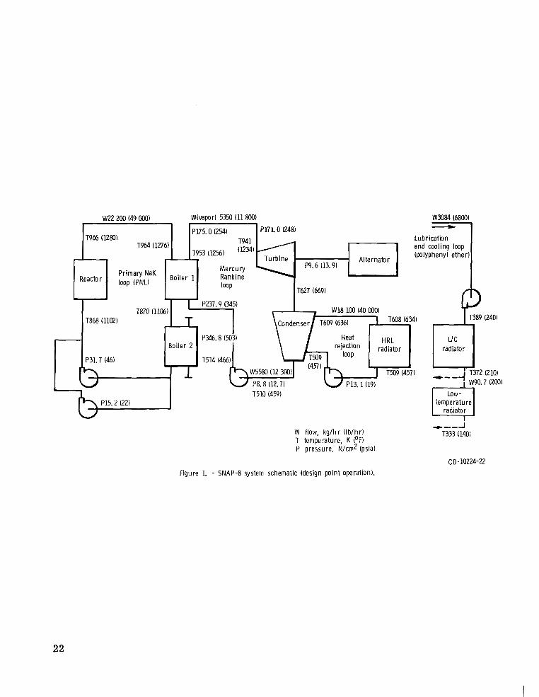
SNAP-8 (System for Nuclear Auxiliary Power) is a 35-kilowatt, reactor-heated, turboelectric, mercury Rankine power system for space application. This system, as currently configured, is composed of the four loops shown in figure 1 and described as follows:
(1) The primary loop employs NaK-78 (eutectic sodium-potassium mixture) to cool the nuclear reactor and to transfer the thermal energy to the mercury loop via the boiler.
(2) In the mercury Rankine loop mercury is preheated, boiled, and superheated in the boiler. The thermal energy is converted into mechanical energy as the mercury vapor is expanded through the turbine, which is directly connected to an alternator for electric power generation. cooled in the condenser and conducted to the pump, which returns the liquid mercury to the boiler.
(3) The heat-rejection loop containing NaK-78 t ransfers the cycle waste thermal energy from the condenser to the radiator for rejection to space.
(4) The lubrication and coolant loop contains polyphenyl ether (4P3E) that is re- quired to lubricate the ball bearings of the rotating components of the mercury and lubricant/coolant systems and to provide cooling for the electric alternator, NaK mo- tors, and control elements.
One of the major problems in the development of the SNAP-8 system has been the attainment of a long-lived, reliable mercury boiler (refs. 1 to 5). The specific prob- lem areas within the SNAP-8 boiler were the degree and stability of wetting of the mer- cury heat-transfer surfaces; pressure drop limitations imposed by reactor tempera- ture excursions; and, most important, the corrosion resistance of the mercury con- tainment material. Early SNAP-8 boilers were constructed of the cobalt-based alloy L-605, which had been successfully used for the SNAP-2 boiler. Unfortunately, the higher operational temperatures of the SNAP-8 boiler (978 K (1300' F) against 922 K (1200' F) for SNAP-2) resulted in an increased and undesirable ra te of corrosion and an embrittlement problem. of alternate materials, which ultimately resulted in the selection of tantalum as the mercury-containment material.
A concept of double containment of the tantalum portions of the boiler w a s devised to prevent the possible transfer of radioactive NaK from the primary loop to the mer- cury loop as the result of a single tube-wall failure (ref. 6). containment concept prevented contamination of the tantalum from oxides or other im- purities possibly contained in the primary NaK. Isolation was attained by the complete envelopment of the tantalum parts with stainless steel. The volume contained between the tantalum and stainless steel w a s filled with static NaK to effect good heat transfer.
The exhaust vapors from the turbine a r e condensed and sub-
These adverse characteristics required the consideration
In addition, the double-
2

Three boilers of this concept were designed and fabricated at Lewis Research Cen- ter. The design, fabrication procedures, and-preliminary testing of the Serial Num- ber 1 boiler have been previously reported in reference 6. The three boilers have sub- sequently been tested successfully over a wide range of operating conditions which encompassed the anticipated SNAP-8 system requirements. The Serial Number 1 unit was tested in an engine loop at Lewis for 1444 hours and in a component test loop at the General Electric Company, Evendale, Ohio, for 13 661 hours (a total of 15 105 hr). No startup tes ts were performed which involved thermal cycling of the boiler NaK from room temperature to 978 K (1300' F) and the injection of cold mercury. This service condition w a s omitted on the Serial Number 1 boiler to minimize thermal shock condi- tions and to preserve the unit for long-term corrosion/erosion examination of the mercury-wetted surfaces. sion System loop at Aerojet Nuclear Systems Company at Azusa for an accumulated total of 8700 hours and 27 startup/shutdown cycles. Thus, the Serial Number 1 and Number 2 boilers have accumulated a combined total of over 23 800 hours of operation at SNAP-8 system conditions. A third unit, Serial Number 3, w a s utilized for system startup/shutdown investigations at Lewis and was successfully subjected to 157 hours of operation and 135 startup/shutdown cycles. The performance of Serial Number 1 and Number 2 boilers and the post-test physical and metallurgical examinations have been previously reported in reference 7. loop at Lewis and has not been examined to date.
has been functionally tested at the Aerojet Nuclear Systems Company for a total of 1620 hours and 28 startup/shutdown cycles. This boiler design included (1) significant changes to the primary NaK flow geometry which were required to correct a NaK flow distribution problem, (2) the provision for additional differential thermal expansion be- tween the tantalum tubes and the surrounding stainless-steel oval tubes, which permitted the elimination of expansion bellows from the boiler assembly, (3) the use of a more reiiable tantalum/stainless-steel bimetal joint, and (4) the attainment of a fully coiled shell assembly. The design changes and fabrication techniques unique to this unit and the preliminary results of the operational performance of the prototype boiler a r e dis- cussed herein.
The design calculations,
The Serial Number 2 unit w a s tested in the Power Conver-
The Serial Number 3 unit is in position in the test
A prototype boiler, designated Serial Number 4, has been fabricated at Lewis and
In this report both SI and U. S. customary units a r e used. measurements, and the data reduction were performed with U. S. customary units.
EXPERIMENTAL SYSTEM
The test facility at Aerojet Nuclear Systems Company in which the Serial Number 4 boiler w a s tested incorporated prototype components for the major hardware with the
3
exception of the heat source and the radiators. A schematic of the proposed flight sys- tem is shown in figure 1. The actual test system substituted a gas-fired NaK heater in place of the reactor and forced-convection-cooled radiators in the heat rejection and lubricant/coolant loops in place of the indicated space radiators. In addition, the re- dundant primary loop NaK pump and the Number 2 boiler were not a part of the test system.
BOILER DESCRIPTION
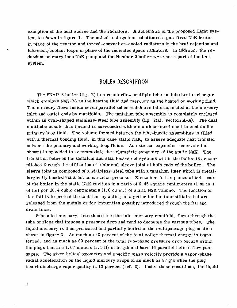
The SNAP-8 boiler (fig. 2) is a counterflow multiple tube-in-tube heat exchanger which employs NaK-78 as the heating fluid and mercury as the heated o r working fluid. The mercury flows inside seven parallel tubes which are interconnected at the mercury inlet and outlet ends by manifolds. The tantalum tube assembly is completely enclosed within an oval-shaped stainless-steel tube assembly (fig. 2(a), section A-A). The dual multitube bundle thus formed is surrounded with a stainless-steel shell to contain the primary loop fluid. The volume formed between the tube-bundle assemblies is filled with a thermal bonding fluid, in this case static NaK, to assure adequate heat transfer between the primary and working loop fluids. An external expansion reservoir (not shown) is provided to accommodate the volumetric expansion of the static NaK. The transition between the tantalum and stainless- steel systems within the boiler is accom- plished through the utilization of a bimetal sleeve joint at both ends of the boiler. The sleeve joint is composed of a stainless-steel tube with a tantalum liner which is metal- lurgically bonded via a hot coextrusion process. Zirconium foil is placed at both ends of the boiler in the static NaK cavities in a ratio of 6.45 square centimeters (1 sq in. ) of foil per 16. 4 cubic centimeters (1.0 cu in.) of static NaK volume. The function of this foil is to protect the tantalum by acting as a getter for the interstitials that a r e released from the metals or for impurities possibly introduced through the f i l l and drain lines.
Subcooled mercury, introduced into the inlet mercury manifold, flows through the tube orifices that impose a pressure drop and tend to decouple the various tubes. The liquid mercury is then preheated and partially boiled in the multipassage plug section shown in figure 3. As much as 40 percent of the total boiler thermal energy is trans- ferred, and as much as 60 percent of the total two-phase pressure drop occurs within the plugs that a r e 1.07 meters (3. 5 ft) in length and have 16 parallel helical flow pas- sages. The given helical geometry and specific mass velocity provide a vapor-phase radial acceleration on the liquid mercury drops of as much as 87 g's when the plug insert discharge vapor quality is 12 percent (ref. 8). Under these conditions, the liquid
4

mercury is separated and forced against the heated tube wall surface to enhance heat transfer. The selection of the multipassage plug design w a s predicated to control the slug flow boiling regime that is believed to be the major cause of poor mercury boiling heat transfer (ref. 8). In the open.tube, downstream of the multipassage plug, a swir l - wire turbulence generator made of tantalum/lO-weight-percent tungsten and 0.16 cen- timeter in diameter by 5. 1 centimeters in pitch (1/16 in. by 2 in. ) is employed to sustain the vortex two-phase flow regime. The effectiveness of the multipassage plug and swirl-wire turbulator in maintaining a vortex two-phase flow regime depends on the existence of the proper pinch-point temperature difference (temperature of NaK minus temperature of the mercury at the liquid/vapor interface) and on the tantalum tube wall surface cleanliness. It has been determined analytically (ref. 8) that a minimum quality of 11 percent must be attained at the end of the plug section to assure the suc- cessful transition of the two-phase flow into the open tube. This results (as indicated in ref. 9) from the need to attain liquid breakup and subsequent entrainment in the vapor stream. According to reference 8, the liquid breakup i s a function of the Weber number
where
6 drop diameter, m (ft) 3 3 pv vapor density, kg/m (lb/ft )
uv vapor velocity, m/sec (ft/sec)
cr surface tension, kg/m (lb/ft)
gc gravitational constant, m/sec 2 (ft/sec 2 )
2 The product pvuv is conveniently determined and is representative of the Weber num- ber. The authors of reference 9 have determined by test that if a value of pvu: of
breakup into the desired vortex flow can be accomplished. From this critical value and for the required boiler conditions a vapor velocity of 3.36 meters.per second (11 ft/sec) w a s calculated. This value has been used as a guide in the thermal design of the plug sections for the SNAP-8 boilers.
212 kilograms per meter per second squared (142 lb/ft-sec 2 ) is attained, liquid
5

DESIGN IMPROVEMENTS
The design and fabrication of the double-containment tantalum/stainless-steel SNAP-8 boilers, Serial Numbers 1, 2, and 3 is.discussed in references 6, 10, and 11. Since that time, various new requirements for the boiler have been imposed and certain desirable changes were indicated from shortcomings in the operational characteristics of the original design. The changes which have been incorporated into the design of the Serial Number 4 boiler are discussed in the following sections.
Thermal-hydraulic performance ~ ~ aspects. .- -- - The thermal-hydraulic performance of the original tantalum/stainless-steel boilers met the requirements of the SNAP-8 sys- tem. Data analyses, however, indicated two areas of possible improvement. These in- volved the large variations in overall boiler mercury pressure drop which were induced by the predicted reactor temperature control deadband, which varied the NaK inlet tem- perature from 966 K (1280' F) to 994 K (1330' F), and the obvious excess boiler super- heating length. The mercury boiling pressure drop variation of 72.4 N/cm (105 psi) at 966 K (1280' F) to 100 N/cm2 (145 psi) at 994 K (1330' F) was caused primarily by the two-phase pressure drop in the multipassage plug. result of better-than-expected thermal performance in this region, which, in turn, re- sulted from the improved wetting characteristics of the tantalum tube wall by the liquid mercury. The original design correlations were based on dry wall boiling (nonwetting) cri teria (ref. 10) which had been employed on previous SNAP-8 boiler design. With the results of single-tantalum-tube boiler tests and the utilization of wetting boiling corre- lations (refs. 12 and 13), it w a s possible to decrease the multipassage plug length from 132 centimeters (52 in.) to 107 centimeters (42 in.). In addition, by minimizing the ex- cess superheating tube length, the overall boiler length w a s reduced to 7.62 centimeters (25 f t ) and the actual mercury boiler pressure drop w a s lessened to 48.3 newtons per square centimeter (70 psi) for a NaK inlet temperature of 966 K (1280' F) and to 65. 5 newtons per square centimeter (95 psi) for a NaK inlet temperature of 994 K (1330' F). Figure 4 illustrates the predicted boiler NaK temperature profiles and mercury temper- ature and pressure profiles for the redesigned Serial Number 4 boiler.
Number 1 and Serial Number 2 boilers indicated the presence of nonuniform shell-side NaK flows (implied from circumferential shell temperature measurements at a given axial location). The NaK inlet and outlet ports on the original boiler shell were single orifice, and thus required the crossover of the NaK fluid in these a reas from one side of the tube bundle to the other, resulting in local flow distribution problems. dition was especially undesirable at the NaK discharge end (mercury inlet) where high heat-flux rates were attainable and a nonuniform heat source could result in serious variations in mercury tube-to-tube thermal-hydraulic performance. In the sections of the boiler shell where the tube/tube/shell spacing w a s to be maintained by mechanical
6
2
The high pressure drops were a
NaK-side flow distribution. - Operation and post-test examination of the Serial
This con-

I
spacers it w a s noted initially by X-raying the boiler that the tube bundle had displaced downward in relation to the shell. This sagging of the tube bundle was attributable to overstressing of the supports at high operating temperatures. The resulting circum- ferential shell temperature profile in the high-heat f lux sections of the boiler (0 to 3. 5 m, o r 0 to 10 f t , from mercury inlet) indicated variations as large as 28 K (50' F). These conditions implied a flow distribution problem. In addition to these problems, there existed doubts concerning the contribution of the flattened stainless-steel tubes (fig. 2(a), section A-A) to NaK flow stratification and the influence of the tube spacing on the proper flow distributions.
important part of a liquid-metal heat exchanger, a program (ref. 14) w a s conducted to study the shell-side hydraulic characteristics of a full-scale SNAP-8 multitube boiler. A Plexiglass model of the boiler (20-ft long) w a s constructed which incorporated
(1) An inlet/exit shell manifold assembly with radial ports on the shell wa l l which
(2) A tube bundle composed of seven prototype stainless-steel oval-shaped tubes (3) A ser ies of five piezometer ring stations which were positioned to investigate
the pressure drop contributions of the various elements of the shell-side geometry
(4) A ser ies of dye-injection ports which were radially adjustable to permit flow studies within the tube bundle o r in the annulus formed between the tube bundle and the shell
geometry
Since the shell- side flow distribution and frictional characteristics are such an
8pportioned the shell-side flow
(5) A bolted end-flange arrangement which permitted rapid changes of the internal
Water w a s used as the test fluid, and pressure loss test data were accumulated and 4 4 correlated over the turbulent Reynolds number range of 1.8X10 to 3. 8x10 . Although
the maximum Reynolds number attained in these tes ts w a s less than that experienced in 5 actual boiler operation (1.6X10 ), care w a s exercised to assure that the Reynolds num-
ber effect w a s fully realized. Friction factors for flow parallel to the tube bundle, with and without turbulence promoters, and loss coefficients for three candidate tube spacer configurations and for the inlet/exit manifolds were determined. In addition, the effect of incoming flow conditions on these loss coefficients were investigated. upstream dye-injection stations, a visual and photographic study w a s made of the shell- side flow distribution, which w a s influenced by various turbulence promoters. From considerations of pressure drop and flow mixing as visually observed during the dye- injection tests a revised shell-side geometry w a s attained that indicated significant im- provements in flow distribution and pressure drop (from 2.4 N/cm (3. 5 psi) to
2 1.7 N/cm (2. 5 psi)). The recommended design changes include inlet and outlet mani- folds (tees) with multiple ports in the NaK shell to attain uniform flow in the end sec- tions; a revised tube spacer design to prevent overstressing of the material and subse-
Utilizing the
2
7
I

quent sagging; a revised tube spacing to apportion the NaK flow-per-tube more uniformly and to minimize bypass flow between the tube bundle and shell; and a w i r e turbulence generator (0. 48 cm (3/16 in. ) diam by 15.2 cm (6-in.) pitch by 2.74 m (9 ft) long) at the NaK discharge end (high-heat-flux section) to induce mixing and to attain a relatively uniform NaK temperature field.
blies and in the manufacture of the tantalum inlet orifices it w a s exceedingly difficult to attain uniformity between assemblies. This was a result of variations in such manu- facturing operations as machining of the plug grooves; mechanical swagging of the tan- talum tube onto the plug; and machining of the plug orifices, which requires precision work. To assure as close a match as possible for the orifice - tube/plug assembly pressure drops, each of the tube/plug assemblies and each of the orifices w a s calibrated with water to determine the actual fluid resistance. After fluid calibration, the compo- nent parts were matched to obtain near uniform pressure drops between assemblies.
Tube bundle design. - In the original tantalum/stainless-steel boilers, two design features of a temporary nature were included to facilitate fabrication and to attain uni- form tube lengths. Because of the inherent difficulties of fully coiling the tube/plug as- semblies (a relatively stiff bar contained within a thin-wall tantalum tube), this fabrica- tion procedure w a s not attempted. This resulted in a 1.78-meter (5. 83-ft) straight section at the mercury boiler inlet and the associated problem of accommodating the large differential thermal expansion between the tantalum and stainless-steel tubes. Expansion bellows were employed for this purpose. In the Serial Number 4 boiler, the technique of fully coiling the plug/tube assemblies was developed, which permitted a fully coiled boiler and the elimination of the bellows.
The tantalum tube lengths in the original boiler assemblies were made equal to minimize possible tube-to-tube performance variations. This w a s accomplished by twisting the tube bundle one revolution throughout the coiled length of the boiler. presented some difficulties as the oval-shaped tube assemblies had to be oriented and maintained in a fixed position during boiler operation with the major oval-tube axis per- pendicular to the axis of the boiler coil to accommodate the radial differential thermal expansion between the tubes. that if the tube bundle was not twisted, the difference in the length between the inner and outer tube coils was approximately 0. 55 meter (1.8 ft). This difference affected only the vapor portion of the tube and w a s calculated to have little effect on overall boiler per- formance. The advantages of th i s design a r e twofold. side tube supports can all be of one design, and the other is the simplification of the assembly procedures. A lattice-type spacer design w a s selected because of i ts simplic- ity, ruggedness, and favorable pressure drop characteristics as discussed in refer- ence 14. Operation of the boiler has verified that the tube length variations do not de- tectably affect overall performance.
8
Orifice - tube/plug assemblies. - In the fabrication of the tantalum plug/tube assem-
This
For the new Serial Number 4 boiler design it w a s found
One advantage is that the shell-

Tube - sizes and wall thicknesses. - The de$ign life of the Serial Number 4 boiler was 40 000 hours. Analysis of the tantalum/stainless-steel tube assemblies indicated the desirability of increasing the tube wall thickpesses and thus increasing the strength and corrosion potential to meet the design life. Another requirement, which resulted from the elimination of the bellows from the boiler assembly, was for the additional clearances between the tantalum and stainless-steel tubes to accommodate the local tube radial movement as a function of differential thermal expansion. needs the wall thickness of both the tantalum and the stainless-steel tubes was increased from 0. 102 centimeter (0.040 in. ) to 0. 124 centimeter ,(O. 049 in. ). outside tube diameter, which prior to flattening w a s 2. 54 centimeters (1 in. ), w a s in- creased to 2. 86 centimeters (18 in.). This provided adequate clearances after flatten- ing for the differential thermal expansion of the tubes in the fully coiled configuration.
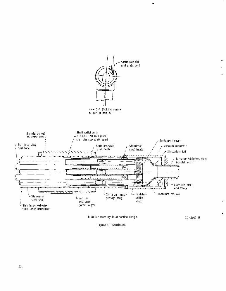
Inlet ______ section temperature gradients. - In most heat-exchanger designs where large temperature differences occur between the heated and heating fluids there exists the potential of overstressing the containment material a t the heated fluid inlet. In the SNAP-8 boiler designs, the stainless-steel header as shown in figure 2(b) has high- temperature NaK on one surface with relatively low-temperature static NaK (cooled by incoming mercury) on the other surface. on the header. To alleviate this possible s t r e s s condition, flow baffles similar to that shown in figure 2(b) a r e placed on the primary NaK side to form a relatively static fluid section which adds an axial resistance to the transfer of thermal energy from the primary flowing NaK to the header. In the original boiler design, two bar r ie rs were provided; however, significant bypass or secondary flow of the primary fluid beyond the baffles w a s possible because of clearances between the baffle and the shell. This flow increased heat transfer in this section of the boiler and contributed to undesirable c i r - cumferential and axial thermal gradients on the shell, which were considered contribu- tory to shell thermal s t r e s s failures which were experienced in th i s area. the'se gradients a revised baffle w a s designed for the Serial Number 4 boiler which w a s integral with the shell and had close clearances between the baffle and tubes (fig. 2(b)). The restricted recirculation flow reduced the temperature gradient across the header and minimized heat transfer to the mercury tubes and therefore reduced the circumfer- ential and radial temperature gradients in this section.
In addition to these modifications, a transient and steady-state thermal analysis of the mercury inlet section (first 45.7 cm (18 in. ) of boiler shell at the mercury inlet end) indicated that an additional thermal resistance w a s necessary to lessen the heat transfer to the liquid mercury and to minimize the associated tube and shell axial thermal gra- dients. tube and surrounding tantalum dome. lar tubes (vacuum insulation) which w e r e positioned as shown in figure 2(b). Test oper- ation of the Serial Number 4 boiler showed, however, that an additional mechanism,
To comply with these
The stainless-steel
1
This could impose significant thermal s t resses
To minimize
The results of this analysis showed the need for insulators on each tantalum The final analysis recommended evacuated annu-
9
natural convection in the section between the stainless-steel header and the end flange, was contributing significant thermal gradients from the top to the bottom of this section. Although no failures resulted from this condition, additional analyses are being per- formed to rectify this condition.
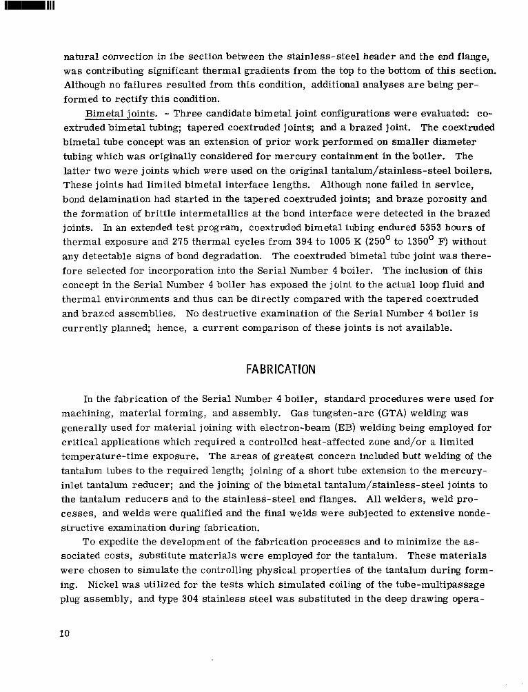
Bimetal joints. - Three candidate bimetal joint configurations were evaluated: co- extruded bimetal tubing; tapered coextruded joints; and a brazed joint. The coextruded bimetal tube concept was an extension of prior work performed on smaller diameter tubing which w a s originally considered for mercury containment in the boiler. The latter two were joints which were used on the original tantalum/stainless-steel boilers. These joints had limited bimetal interface lengths. Although none failed in service, bond delamination had started in the tapered coextruded joints; and braze porosity and the formation of'brittle intermetallics at the bond interface were detected in the brazed joints. In an extended test program, coextruded bimetal tubing endured 5353 hours of thermal exposure and 275 thermal cycles from 394 to 1005 K (250' to 1350' F) without any detectable signs of bond degradation. fore selected for incorporation into the Serial Number 4 boiler. The inclusion of th i s concept in the Serial Number 4 boiler has exposed the joint to the actual loop fluid and thermal environments and thus can be directly compared with the tapered coextruded and brazed assemblies. No destructive examination of the Serial Number 4 boiler is currently planned; hence, a current comparison of these joints is not available.
The coextruded bimetal tube joint w a s there-
FA BR KAT1 ON
In the fabrication of the Serial Number 4 boiler, standard procedures were used for machining, material forming, and assembly. Gas tungsten-arc (GTA) welding was generally used for material joining with electron-beam (EB) welding being employed for critical applications which required a controlled heat-affected zone and/or a limited temperature-time exposure. The a reas of greatest concern included butt welding of the tantalum tubes to the required length; joining of a short tube extension to the mercury- inlet tantalum reducer; and the joining of the bimetal tantalum/stainless-steel joints to the tantalum reducers and to the stainless-steel end flanges. All welders, weld pro- cesses, and welds were qualified and the final welds were subjected to extensive nonde- s truc tiv e examination during fabrication.
sociated costs, substitute materials were employed for the tantalum. were chosen to simulate the controlling physical properties of the tantalum during form- ing. Nickel w a s utilized for the tests which simulated coiling of the tube-multipassage plug assembly, and type 304 stainless steel w a s substituted in the deep drawing opera-
To expedite the development of the fabrication processes and to minimize the as- These materials
10
tion which was required to form the inlet and exit tantalum reducers. These materials were quite effective for these processes and tl-ieir use saved considerable time and ex- pense.
The machining techniques employed were, as mentioned previously, standard and therefore a r e not discussed in detail. The machining of tantalum w a s difficult because of a galling tendency which complicated the trepanning o r cutting of concentric grooves in the tantalum headers surrounding each of the seven tube holes and the machining of the spiral grooves in the multipassage plugs. The trepanning w a s accomplished by the use of a formed electrode and the electrical discharge machine (EDM) process. The tantalum multipassage plug fabrication w a s accomplished through the synchronization of a ball end milling cutter by the use of an indexing head, end table gear train, and work table lead screw to produce the required 15.2-centimeter (6-in. ) pitch. The tool cutting depth w a s small and a profuse flow of cutting oil w a s maintained throughout the machining phase.
Stress analysis of the boiler revealed, however, the presence of relatively high s t r e s s loadings in the a rea of curvatures of the reducers. strength in these areas , i t w a s necessary to employ tantalum sheets which possessed a fine grain structure and relatively high strength. The cold working performed on this component further increased the margin of strength. To maintain th i s margin the electron-beam weld process w a s employed. This prevented overheating of large areas of the reducers, which would have a tendency to produce grain growth and subsequently reduce strength.
cussion. The boiler w a s to be used in a high-temperature liquid-metal system which required a high level of cleanliness. Since many sections of the boiler would be inac- cessible for cleaning after assembly, adequate precautions were taken to assure cleanli- ness of the hardware throughout the fabrication phase. All par ts were solvent cleaned and bagged in plastic after machining or forming to prevent contamination during han- dling and transport to the assembly area. All assembly procedures were performed in a room with a controlled environment. All hardware w a s handled with white gloves to prevent possible contamination from the assemblers' hands.
minimize tube welds. Those sections which contained the plugs were cut to 1. 83-meter (6-ft) lengths to facilitate assembly. positioned, and the tube w a s swaged onto the plug. The resultant close-fitting tube/plug assembly held the plug in position and prevented mercury from flowing over the lands during the operation of the boiler. The w i r e turbulators downstream of the plugs were made from 0. 158-centimeter (1/16-in. ) diameter tantalum/lO-weight-percent-tungsten w i r e on a 5.08-centimeter (2-in. ) pitch. The use of cold-worked tantalum/lO-weight-
The tantalum reducers were originally conceived as being machined from a slab.
To provide adequate material
A chronological sequence of the assembly procedure is detailed in the following dis-
The tantalum tube was obtained in 3.66- to 4.88-meter (12- to 16-ft) lengths to
The plug w a s inserted into a section of tubing and
11
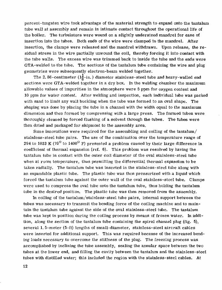
percent-tungsten w i r e took advantage of the material strength to expand onto the tantalum tube wall at assembly and remain in intimate contact throughout the operational life of the boiler. The turbulators were wound on a slightly undersized mandrel for ease of insertion into the tubes. Both end's of the w i r e were clamped to the mandrel. After insertion, the clamps were released and the mandrel withdrawn. Upon release, the re- sidual s t ress in the wire partially unwound the coil, thereby forcing it into contact with the tube walls. The excess wire was trimmed back to inside the tube and the ends were GTA-welded to the tube. The sections of the tantalum tube containing the w i r e and plug geometries were subsequently electron-beam welded together.
sections were GTA-welded together in a dry box. allowable values of impurities in the atmosphere were 5 ppm for oxygen content and 10 ppm for water content. After welding and inspection, each individual tube was packed with sand to limit any wall buckling when the tube was formed to an oval shape. The shaping was done by placing the tube in a channel with the width equal to the maximum dimension and then formed by compressing with a large press. thoroughly cleaned by forced flushing of a solvent through the tubes. The tubes were then dried and packaged for shipment to the assembly area.
stainless-steel tube pairs. The use of the combination over the temperature range of 294 to 1033 K (70' to 1400' F) presented a problem caused by their large difference in coefficient of thermal expansion (ref. 6). This problem w a s resolved by having the tantalum tube in contact with the outer coil diameter of the oval stainless-steel tube when at room temperature, thus permitting the differential thermal expansion to be taken radially. The tantalum tube. was inserted in the stainless-steel tube along with an expandable plastic tube. The plastic tube was then pressurized with a liquid which forced the tantalum tube against the outer wal l of the oval stainless-steel tube. Clamps were used to compress the oval tube onto the tantalum tube, thus holding the tantalum tube in the desired position.
In coiling of the tantalum/stainless- steel tube pairs, internal support between the tubes w a s necessary to transmit the bending force of the coiling machine and to main- tain the tantalum tube against the side of the oval stainless-steel tube. The tantalum tube w a s kept in position during the coiling process by means of frozen water. In addi- tion, along the section of the tantalum tube containing the spiral channel plug (fig. 5), several 1. 5-meter (5-ft) lengths of small-diameter, stainless-steel aircraft cables were inserted for additional support. This was required because of the increased bend- ing loads necessary to overcome the stiffness of the plug. accomplished by inclining the tube assembly, sealing the annular space between the two tubes at the lower end, and filling the cavity between the tantalum and the stainless-steel tubes with distilled water; this included the region with the stainless-steel cables. At
1 The 2.86-centimeter (lg-in. ) diameter stainless-steel tube and heavy-walled end In the welding chamber the maximum
The formed tubes were
Some innovations were required for the assembling and coiling of the tantalum/
The plastic tube w a s then removed from the assembly.
The freezing process w a s
12

the elevated end a reservoir was used to remove or supply water as required to keep the tube completely filled. Cold alcohol w a s then pumped through the inner tantalum tube. carbon dioxide in a container. The water froze from the low end and the excess result- ing from the expansion merely flowed out the open end. When the water w a s completely frozen, the tantalum/stainless-steel tube pairs were coiled while maintaining active flow of the alcohol. tantalum/stainless-steel tube pair be coiled using three different values of radii. Ac- cordingly, different curvature settings were necessary on the coiling machine. Tem- plates, in conjunction with predetermined tangent points along the tube length, were used to guide the coiling of the tubes. Also, three separate groups of tantalum/ stainless-steel tube pairs were coiled, for a total of seven tube pairs differing only in coil radii dimensions. The coiling did not give a uniform pitch to the tubes, so this was done manually by expanding the coils and inserting spacers to maintain the proper spac- ing and support (fig. 6). A fixture w a s used for assembling the tube bundle. The in- dividual pairs were threaded through the fixture brackets one at a time with the small coil diameters being the first. The tube-bundle spacers were positioned and welded (fig. 7). The outside-diameter containment shell w a s coiled separately. The large 12. "-centimeter (5-in, ) outside diameter (0. d. ) tube w a s filled with natural t ree resin to uniformly transmit the bending loads and to maintain a circular tube c ross section while being coiled to the approximate coil diameter. drained from the shell and replaced with water. Utilizing high-pressure water pulses, the 12. 7-centimeter (5-in. ) 0. d. tube coil w a s sized to final dimensions. After coiling, the tube diameter varied to an acceptable 4 . 0 4 0 centimeter (*1/64 in. ). The tube w a s trimmed to length and then cut in segments for ease of handling when threading onto the tube bundle (fig. 8). a solvent through the tubes. assembly area.
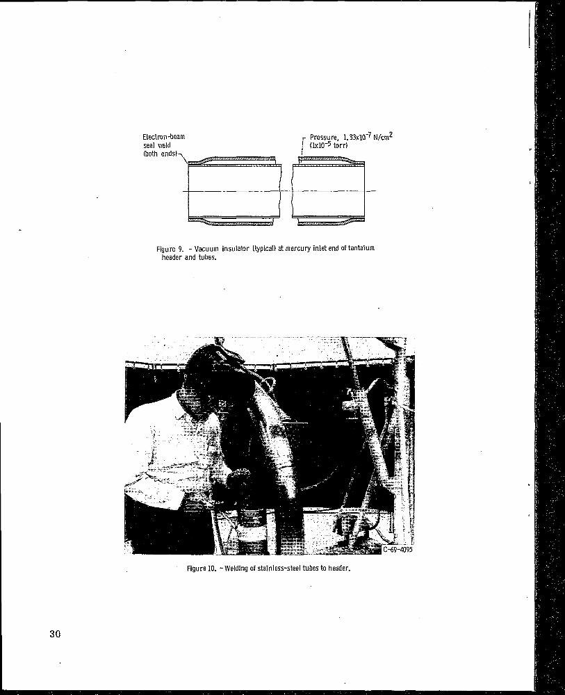
sulators (fig. 9), which were EB-welded in the vacuum chamber, all welding w a s done by the GTA process. During the welding of the stainless-steel tubes to the headers, a positive flow backup gas (argon) at 2.8 newtons per square centimeter (4 psi) was main- tained on the inside of the boiler (fig. 10). When tantalum components were welded during the boiler assembly, a portable glove box (fig. 11) w a s used. The assembly and box were purged with argon until the oxygen concentration in the enclosure w a s less than 10 ppm. Just before welding the tantalum, an a r c w a s struck to a piece of titanium in the box to getter part of the remaining oxygen. On a large tantalum weld, periodic checks of oxygen content in the box were made. Every weld w a s helium-leak and dye- penetrant checked before proceeding to the next operation.
The cooling of the alcohol w a s accomplished by passing the alcohol over frozen
The physical dimensions of the boiler assembly required that each
The t ree resin w a s melted and
The tube segments were thoroughly cleaned by forced flushing of The tubes were then dried and packaged for shipment to the
With the exception of the mercury inlet/outlet subassemblies and the vacuum in-
13

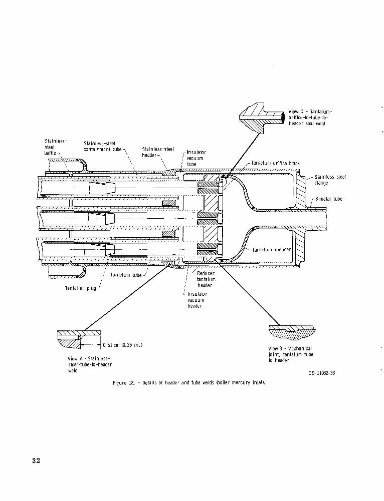
The stainless-steel tube stubs were positioned with 0.64-centimeter (1/4-in. ) of the tube extending from the header (fig. 12, view A). This extension protected the t a n t a l k during welding and allowed a heavy fille'r pass to be made after the full- penetration seal weld. The results can be seen in figure 13.
in the stainless-steel oval coil to position the tantalum tubes at the maximum coil di- ameter. The tantalum tubes were mechanically attached to the headers with a special tool (fig. 12, view B) by radially expanding the tubes into the grooves in the headers (fig. 12). The orifice blocks were inserted into the tube-header assembly and a seal weld joined the orifices and tubes to the tantalum headers (fig. 12, view C). A pre- welded subassembly of the transition dome, bimetal joint, and shell end (figs. 14 and 15) was GTA-welded to the tantalum header. The enclosure and seal weld for the contain- ment of the static NaK at the shell end flange and bimetal joint (fig. 16) utilized the electron-beam weld method. The metallurgical bond between the dissimilar metals (stainless steel and tantalum) of the bimetal tube w a s not imparied. The combination of welding variables resulted in a minimum of sputtering of the metal on the back face of the flange and this was subsequently removed by machining. Zirconium foil, which acts as a getter for possible interstitials, was wrapped around the bimetal joint. The final closure, a short section of 13-centimeter (53-in.) 0.d. tube which completed the shell assembly, was welded in place. The completed boiler is shown in figure 17.
but a great deal of care w a s taken to assure that all steps were correctly completed. Machined par ts that required weld preparations had an offset pilot-diameter step to facilitate their centering and positioning for welding. Mating pieces, as required, were tacked together along the periphery at selected points, followed by full-penetration fu- sion welds. The thicker welds were initially Tusion-welded and then followed by filler welds. On the mercury inlet/outlet transition domes, tantalum electron-beam butt welds were made with a tantalum backup ring to minimize sputtering of the internal weld sur- face.
ultrasonic, o r radiographic inspection, o r partially destructively examined by metallur- gical methods as required. sional accuracies per print and the deviations were recorded. the tube bundle and on the mercury inlet and outlet subassemblies were radiographically inspected and destructively examined to verify welding procedures. Helium leak checks were conducted for each of the containments (mercury, primary NaK, and static NaK) as the assembly progressed to ensure integrity of the welds.
At this point, the tantalum tubes which were pretrimmed to length were repositioned
1
The fabrication and assembly procedure was relatively simple and straightforward,
All materials upon receipt were visually and nondestructively examined by penetrant,
Fabricated and machined par ts were inspected for dimen- Specimens of welds on
14

BOILER PERFORMANCE
The Serial Number 4 boiler w a s tested in the Power Conversion System test facility at the Aerojet Nuclear Systems Company during the time period of March 12, 1970, to May 28, 1970. The testing consisted of 1619.7 hours of accumulated run time and 28 thermal cycles. During this period, extensive boiler mapping w a s accomplished. Mapping w a s performed over the boiler design range (table I) with an inlet NaK temper- ature of 977 K (1300' F) nominal, and over a second range (table II) with an inlet NaK temperature of 922 K (1200' F) nominal which encompassed a proposed new set of de- sign conditions for the Power Conversion System. The second range of cycle conditions was investigated for a reactor-outlet temperature range of 914 to 928 K (1185' to 1210' F), an increased mercury.flow rate of 6400 kilograms per hour (14 120 lb/hr), and a boiler discharge pressure of 100 newtons per square centimeter (145 psia). This range w a s simulated on a per-tube basis with the required number of boiler tubes in- creased from 7 to 12 for the proposed conditions. The performance of the boiler for both sets of conditions w a s excellent. Recorded boiler discharge pressure variations at the design conditions of 977 K (1300' F) NaK inlet temperature and rated mercury flow was less than 4. 7 newton per square centimeter (A psi).
formance over a wide range of operating conditions (ref. 15). following range of independent parameters:
General steady-state mapping of the boiler w a s performed to observe the boiler per- The mapping covered the
Mercury flow, kg/hr (lb/hr) . . . . . . . . . . . . . . . . . 1361 to 5443 (3000 to 12 000) NaK flow, kg/hr (lb/hr) . . . . . . . . . . . . . . . . 11 330 to 22 200 (25 000 to 49 000) NaK inlet temperature, K (OF) 894 to 977 (1150 to 1300) . . . . . . . . . . . . . . . . . .
A ser ies of plots of the data generated a r e shown in figures 18 to 21. Figure 18 shows the overall mercury boiler pressure drop (includes boiler inlet orifice pressure drop) as a function of the independent parameters NaK flow rate, boiler NaK inlet tem- perature, and mercury flow rate. The magnitude of the pressure drop w a s in accord- ance with the computer analysis predictions (fig. 4). The only undesirable performance characteristic w a s a negative slope of the mercury pressure drop as a function of in- creasing mercury flow rates. This condition a r i ses as a result of the restricted flow passages in the plug section and the associated, relatively high, two-phase pressure drop. At low mercury flow rates, boiling is initiated at or before the plug entrance, re- sulting in two-phase pressure loss throughout the plug length. As the flow rate is in- creased the plug pressure drop increases until a point is reached where the liquid/vapor interface is displaced downstream of the plug entrance as a function of the increased flow rate and heat transfer in this region. The movement of the interface downstream lessens the two-phase length in the plug and the associated pressure drop, which results
15

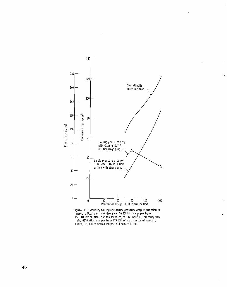
in an inflection of the mercury pressure drop curve and a negative slope as shown in figures 18 and 19. This characteristic had existed on all previous boilers containing a plug section and neither was this characteristic .considered detrimental to the system operation nor w a s a positive pressure slope required in the boiler specifications. This viewpoint has changed, however, as it has been demonstrated that the negative slope characteristic is undesirable to the operation of the system. To correct this problem, a straightforward solution w a s to increase the liquid-phase orifice pressure drop. An analysis of this problem for the proposed 922 K (1200' F) NaK inlet temperature system has been performed and figure 22 illustrates the pressure drop required to ensure a positive pressure slope under all predicted boiling conditions.
pressure drop has been subtracted from the total pressure drop and therefore, rep- resents that pressure drop associated with the preheat, boiling, and superheat phases of the boiler operation. negative slope, the removal of the orifice pressure drop, which has a positive slope as a function of increased flow, accentuates the negative slope, as shown.
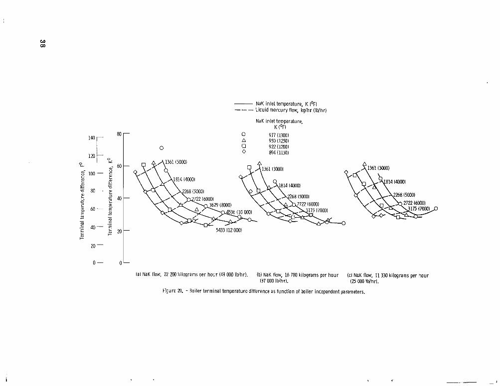
The measured terminal temperature difference (NaK inlet temperature minus mer- cury discharge temperature) as a function of the independent parameters is presented in figure 20. The terminal temperature difference range of 22 to 28 kelvin degrees (40 to 50 Fahrenheit degrees) shown for the design conditions of 5443 kilograms per hour (12 000 lb/hr) mercury flow and 977 K (1300' F) NaK inlet temperature is in accordance with past test experience. The mercury temperatures measured during this test se r ies were obtained from surface thermocouples on the vapor line. This was necessary be- cause of the loss of immersion thermocouples at this location. Pr ior test experience, however, has shown that the mercury vapor stream temperatures a r e approximately 17 kelvin degrees (30 Fahrenheit degrees) higher than that indicated by the surface thermocouple pickups. Applying this correction, the data shown for the terminal tem- perature difference would be in the range 5.6 to 11.1 kelvin degrees (10 to 20 Fahrenheit degrees), which agrees with the design expectations. The pinch-point temperature dif- ference (minimum temperature difference between the NaK and mercury fluids at the liquid/vapor interface) is shown in figure 2 1 as a function of NaK flow rates, boiler NaK inlet temperatures, and mercury flow rates. As illustrated, the pinch-point tempera- ture difference w a s varied over a wide range from about 5.6 to 222 kelvin degrees (10 to 400 Fahrenheit degrees).
The stability of the boiler at both system design conditions, as measured by the fluctuations in the mercury vapor discharge pressure, w a s excellent. The magnitude of pressure variations was less than *1 percent of the discharge pressure at the design conditions (NaK inlet temperature, 977 K (1300' F)) and less than A2 percent at the pro- posed conditions (NaK inlet temperature, 922 K (1200' F)). These magnitudes of pres- sure variations are considered to be representative of a stable once-through boiler. As
16
Figure 19 shows the same data as presented in figure 18 except that the inlet orifice
Since it is characteristic of th i s boiler design to operate with a

the operating conditions were moved off -design in each direction, variations in mercury discharge pressure were obtained. Figure 23 bhows time plots of the boiler outlet pres- sure for the various off -design conditions investigated. lations observed occurred when the mercury flow rate w a s 4912 kilograms per hour (10 830 lb/hr) with a NaK flow rate of 22 000 kilograms per hour (48 500 lb/hr) and with a NaK inlet temperature of 919 K (1194' F) (test condition 7, fig. 23) and coincided with the minimum indicated pinch-point temperature difference of all tests (4. 5 K o r %8' F). At this condition, the oscillations were about i4 percent. All test data within the design ranges of tables I and II showed pressure perturbations too low to respond to the instru- mentation systems used and a r e therefore not shown.
Portions of the boiler mapping were designed to specifically identify the boiler per- formance at the revised 922 K (1200' F) nominal NaK inlet temperature state point. This state point w a s represented with a mercury liquid flow rate of 3629 kilograms per hour (8000 lb/hr) (for the existing seven-tube configuration), a NaK flow rate of 14 740 kilograms per hour (32 500 lb/hr), and a NaK inlet temperature of 922 K (1200' F). These conditions, on a per-tube basis, closely simulated operation at the revised state point. The total mercury pressure drop (including orifice pressure drop) shown in figure 24 as a function of the mercury flow rate and different boiler NaK inlet temperatures again illustrates the negative pressure drop - flow rate slope of the boiler. earlier, this characteristic is easily remedied with the appropriate inlet orifices.
Terminal temperature difference is shown as a function of mercury flow rate and the NaK inlet temperature in figure 25. The general value of this difference is about 25 to 30.6 kelvin degrees (45 to 55 Fahrenheit degrees). When corrected to the equiva- lent of an immersion thermocouple reading, this represents a difference of about 11. 1 kelvin degrees (20 Fahrenheit degrees), which is consistent with the design expec- tations.
Test condition 10 (fig. 23) presents boiler stability data for operation in the vicinity of the revised state point. The general fluctuation of the mercury outlet pressure is l e s s than & percent of the rated pressure and is within the current design requirements. The overall performance of the boiler at the revised power conversion system conditions w a s excellent.
A test w a s conducted to evaluate the response of the system to the normal variations of the boiler NaK inlet temperature over the reactor temperature control deadband for the revised state point. The testing w a s extended over a wider range of NaK inlet tem- perature variations than anticipated to increase the accuracy of the data interpretation, and w a s conducted by changing only the boiler NaK inlet temperature. band temperature extremes for the revised state point a r e 914 to 928 K (1185' to 1210' F).
The maximum pressure oscil-
The performance of the boiler a t these conditions is presented in figures 24 to 26.
As discussed
The reactor dead-
The testing range, however, w a s extended as shown in figures 26(a) and (b)
17

to a wider range of 904 to 941 K (1170° to 1235' F). tem key parameters were in accordance with expectations. As the boiler NaK inlet tem- perature increased (other independent parameters unchanged) the available boiler pinch- point temperature difference increased. This increased the thermal potential at the liquid/vapor interface and caused a shifting of the interface upstream in the plug, de- creasing the boiler inventory and increasing the boiler pressure drop (because of the increased two-phase plug boiling length). As the boiler pressure drop increased, the boiler inlet mercury pressure increased. This added resistance to the mercury pump output was somewhat modified by the increased mercury pump suction head (because the displacement of boiler inventory to the condenser raised the liquid/vapor interface and thus the available head). The overall effect, however, was to slightly lessen the mer- cury flow rate, as shown. This decreased flow rate resulted in less heat input to the working fluid. The reduced available energy to the turbine-alternator resulted in a slight reduction in alternator output power, as shown. exhaust pressure) also w a s reduced because the available coolant flow rate in the heat- rejection loop was constant, whereas the mercury flow rate had been lessened.
The responses of the various sys-
The condenser pressure (turbine
CONCLUDING REMARKS
The successful operation of the Serial Number 4, prototype tantalum/stainless-steel,
Those changes beneficial to the boiler structural integrity and performance include double-containment, mercury boiler verified the design changes incorporated in this unit. the following:
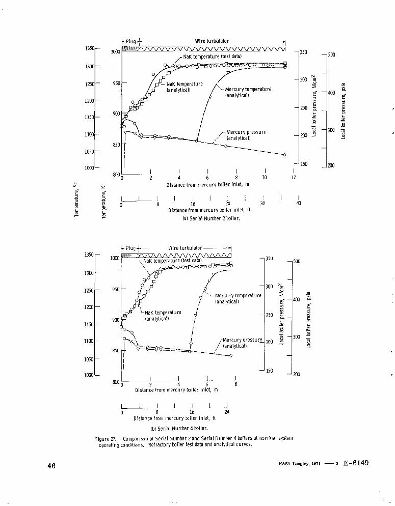
1. For the 977 K (1300' F) system, the effective boiler length was decreased from 11. 3 meters (37 ft) (as used in Serial Number 1, 2, and 3 boilers) to 7 . 6 meters (25 ft) (as used in Serial Number 4 boiler) and the multipassage plug length w a s shortened from 132 centimeters (52 in. ) to 107 centimeters (42 in. ). These changes resulted in no change in overall thermal performance (see fig. 27). However, the two-phase pressure drop was reduced by approximately 28 newtons per square centimeter (40 psi) a t nominal operating conditions.
shell radial ports and associated collector rings (tees) increased tube spacing, revised tube supports, and a coiled-wire flow turbulator 2. 74 meters (9 ft) long in the high-heat- flux section) was modified. uniform NaK shell circumferential temperature field, and reduced variations in the boiler discharge pressure.
tube dimensions used to accommodate the differential thermal expansion of the
2. The primary NaK-side flow geometry (which included inlet and outlet multiple-
This resulted in reduced NaK-side pressure drop, a more
3. The straight-end-section lengths of the boiler were minimized and the flattened
18

tantalum/stainless-steel tubes were increased. expansion bellows a t the boiler mercury inlet and the attainment of a fully coiled boiler assembly .
and the matching of these components to attain relatively uniform pressure drops be- tween tubes was instrumental in achieving the minimum boiling pressure variations.
5. Use of the coextruded bimetal joint as the interface between the tantalum and stainless-steel portions of the boiler permitted a shortened static NaK section and con- tributed to the attainment of a fully coiled boiler. In addition, it is believed that because of the longer bimetallic interface, this joint is inherently more reliable than the other candidate bimetal joints.
6. The fabrication techniques necessary to the coiling of the tube/plug assembly were successfully accomplished with no excessive local deformation of the tantalum tube wa l l at the plug end.
outlet were successfully welded to the boiler stainless-steel end flanges without any sign of joint degradation (the formation of brittle intermetallics as a function of high temper- atures and exposure time). This w a s accomplished by the use of an electron-beam (EB), full-penetration weld which minimized the peak temperature and temperature exposure time at the joint interface.
This permitted the elimination of the
4. Individual flow calibration of the mercury inlet orifices and tube/plug assemblies
7. The coextruded bimetal joints which were used on both the mercury inlet and
Lewis Research Center, National Aeronautics and Space Administration,
Cleveland, Ohio, May 5, 1971, 120-27,
REFERENCES
1. Emmet, W. L. R. ; and Sheldon, L. A. : The Emmet Mercury-vapor Process. Mech. Eng., vol. 46, 1924, pp. 253-285.
2. Hackett, H. N. : Mercury for the Generation of Light, Heat, and Power. Trans. ASME, vol. 64, no. 7, Oct. 1942, pp. 647-656.
3. Smith, A. R. ; and Thompson, L. S. : New Mercury-vapor Power Plant. Steel, vol. 110, no. 2, Jan. 12, 1942, pp. 52-53, 84, 87-88.
4. Gido, R. G. ; Koestel, A. ; Haller, H. C. ; Huber, D. D. ; and Deibel, David L. : Topical Report No. 12. Boiler Development. Rep. ER 4521, TRW, Inc. (AEC Rep. NAA-SR-6304), Apr. 9, 1962.
19
5. Clark, L. T. : A Summary of Literature on Relations Between Wetting and Boiling Mercury Heat Transfer. Rep. AN-766; Aerojet-General Nucleonics, Nov. 1962.
6. Gertsma, Laurence W. ; and Medwid, David W. : Design and Fabrication of a Counterflow Double-Containment Tantalum - Stainless Steel Mercury Boiler. NASA TN D-5092, 1969.
7. Furman, E. R.; Brooks, R. D.; and Harrison, R. W.: Experimental Evaluation of Tantalum/Stainless Steel Mercury Boilers for the SNAP-8 System. Presented at the AIAA Fifth Intersociety Energy Conversion Engineering Conference, Las Vegas, Nev. , Sept. 21-24, 1970.
8. Sellers, A. J. : Forced Convection Mercury Boiling - Experimental Investigation Using a Helical Multipassage Plug Insert in a Once-Through Boiler. Tech. Memo. 4934:67-459, Aerojet-General Corp. , Mar. 31, 1967.
9. Gido, R. G.; and Koestel, Alfred: The SNAP-II Power Conversion System. Top- ical Report No. 17, Mercury Boiling Research Rep. ER-4833, TRW, Inc. (AEC Rep. NAA-SR-6309), Oct. 1962.
10. Sellers, A. J. : Bare Refractory Double Containment Boiler Design Analysis. Tech. Memo 4934:67-477, Aerojet-General Corp. , June 30, 1967.
11. Gertsma, L. W.; Thollot, P. A. ; Medwid, D. W. ; and Sellers, A. J. : The Double Containment Tantalum-Stainless Steel SNAP-8 Boiler. society Energy Conversion Engineering Conference. Vol. 1. IEEE, 1968, pp.
Proceedings of the Inter-
363-369.
12. Poppendick, H. F.; Green, N. D.; Sabin, C. M.; Feigenbutz, L. V.; and Mouritzen, G. : High Acceleration Field Heat Transfer for Auxiliary Space Nu- clear Power Systems. Rep. GLR-42, Geoscience, Ltd. (AEC Rep. SAN-409-29), Jan. 1966.
13: Anon. : Two-Phase Flow Pressure Drop and Heat Transfer in a Multislot Insert in the Entrance of a Boiler Tube. Rep. GLM-61, Geoscience, Ltd. , Nov. 1967.
14. Hsia, Edward S. ; Fuller, R. A. : Shell Side Hydraulic Characteristics of a Full- Scale SNAP-8 Multiple Tube Model Boiler. NASA CR-72830, 1971.
15. Hodgson, J. N. : PCS-1 Testing of March-May 1970. Tech. Memo. 7992:70-633, Aerojet-General Corp. , Aug. 4, 1970.
20

TABLE I. - DESIGN BOILER OPERATING PARAMETERS
[35 kWe; inlet NaK temperature , 977 K (1300' F) nominal.] - NaK inlet temperature , K (OF):
Low . . . . . . . . . . . . . . . . . . . . . . . . . . . . . . . . . . . . . . Nominal . . . . . . . . . . . . . . . . . . . . . . . . . . . . . . . . . . . . High. . . . . . . . . . . . . . . . . . . . . . . . . . , . . . . . . . . . . .
. . . . . . . . . . , . . . . . . . . . . . . .
966 (1280) 980 (1305) 994 (1330) 94.4 (170)
. . . . . . . . . . . . . . . . . . 22 200 (49 000) 2 .1 (3)
. . . . . . . . 533 (500) 179 (260)
. . . . . . . . . . . . . . . . . . . . . . 5580 ( 1 300) 16.7 (<30)
NaK temperature drop, KO (Fo) NaK flow ra te , kg/hr (lb/hr) . . . . . NaK p r e s s u r e drop (maximum), N/cm Mercury inlet temperature , K ( O F )
Mercury exit p ressure , N/cm (psia) . . . . . . . . . . . . . . . . . . . . . . Mercury flow ra te , kg/hr (lb/hr) Termina l temperature difference, (TNaKin - T
Mercury vapor p r e s s u r e variations, percent of mercury
Liquid-mercury car ryover (maximum), percent
i (psi) . , . . . . . . . . . . . . . . . . . . . . . . . . . . . . . . .
2
), KO (Fo) . . . . . . Hgout
discharge p r e s s u r e . . . . . . . . . . . . . . . . . . . . . . . . . . . . . : . , ' t l (s'*t) I I . . . . . . . . . . . . . . . . 4 (,, 4)
TABLE II. - PROPOSED DESIGN BOILER OPERATING PARAMETERS
[92. 8 kWe; inlet NaK temperature , 922 K (1200° F) nominal.] ~~~
NaK inlet temperature , K ( O F ) :
L o w . . . . . . . . . . . . . . . . . . . . . . . . . . . . , . . . . . . . . . . 914(1185) Nominal . . . . . . . . . . . . . . . . . . . . . . . . . . . . . . . . . . . . 922 (1200)
High . . . . . . . . . . . . . . . . . . . . . . . . . . . . . . . . . . . . . . 928 (1210) NaK temperature drop, K O (Fo) . . . . . . . . . . . . . . . . . . . . . . . . . 94. 5 (170)
NaK flow ra te , kg/hr (lb/hr) . . . . . . . . . . . . . . . . . . . . . . . 25 880 (57 050) NaK p r e s s u r e drop (maximum), N/cm (psi) . . . . . . . . . . . . . . . . , . . 2. 1 (3)
Mercury inlet temperature , K ( O F ) . . . . . . . . . . . . . . . . . . . . . . . 450 (350) Mercury exit p ressure , N/cm (psia) . . . . . . . . . . . . . . . . . . . . . . 102 (148) Mercury flow rate , kg/hr (lb/hr) . . . . . . . . . . . . . . . . . . . . . . 6405 (14 120)
2
2
Terminal temperature difference, (TNaKin - T
Mercury vapor p r e s s u r e variations, percent of mercury
), KO (Fo) . . . . . . . <16.7 (<30) Hgo" t
discharge p r e s s u r e . . . . . . . . . . . . . . . . . . . . . , . . . . . . . . < -tl (< *l)
<4 (<4) Liquid-mercury car ryover (maximum), percent . . . . . . . . . . . . . . . . . .- ___~. .
21
CD-10224-22 Figure 1. - SNAP-8 system schematic (design point operation).
22

and dra in port _ _ - ~
Section B-B
(a) Boiler configuration.
Mercury discharge
' CD-11033-33 Figure 2. - Prototype SNAP-8 tantalum/ stainless-steel double-containment mercury boiler (Ser ia l Number 4).
23
View C-C (looking normal to axis of item 5)
*
Stainless-steel collector (tee),
I I
Shel l radial ports .- 3.8-cm (1. %-in.) diam, / six holes spaced 60' apart Tantalum header
/ / Stainless-steel I ,- Stainless-steel ,- Stainless- /' Vacuum insulator I ^ I uval tube
m/stainless-steel
'- Stainless-steel
\ \ \ \ \ \ \ \ \ \=\\ \ , I \
Tantalum m u l t i - L Tantalum \L Tantalum reducer i '\
I Stainless- I i n s u I ato r block steel shel l I or i f i ce Vacuum passage plug.
Stainless-steel-wire turbulence generator
(seven req'd)
(b) Boiler mercury in le t section design.
Figure 2. - Continued.
CD-11030-33
24

Stainless-
>
Stainless-steel header,
Tantalum reducer-
,-Stainless-steel she l l
-3.8-cm (1. %-in. 1 diam, six holes spaced 60° apart
- Tantal urn header
iTantalumlstainless-steel bimetal jo in t
Section D-D (rotated 33' ccw)
(c) Boiler mercury outlet section design.
Figure 2. - Concluded.
25

,- 16 Grooves, 15.2 (6.00) lead equally spaced; lead angle, 71'30' (1,248 rad) ref. based 1
(0.49) 7
, places I
32 places
Section A-A
Figure 3. - Multipassage p lug inser t design. Dimensions are in cm (in. 1.
C D-11031-33

0
Plug inser t Swir l w i re -
1250 LI 0
pi
a 1200- m, 2i
L
&- E 1150-
1100
1050
l3O0 t - x
2 E E
3 c
n
I--
-
I
I- LOW -
Nak in le t
Mercu ry discharge
800 I l l l l l l l l l l
W- L
L n VI W L n
U L U
250 L I 10
Distance f rom boi ler inlet, m
L I I I I d 0 5 10 15 20 25 30
Distance f rom boi ler inlet, f t
F igure 4. - Ser ia l Number 4 boiler predicted axial temperature and pressure pro- files.
27

Oval stainless- steel tube -,
r A i r c r a f t cables
I C D- 11034-33
Figure 5. - Cross section o f tantalumlstainless-steel tube p a i r wi th small-diameter, stainless-steel a i rc ra f t cables inserted fo r coi l ing p lug section.
+
Figure 6. -Method used to establish pitch on tantalumlstainless-steel tube assemblies.
28

Figure 7. -Welding of tube-bundle spacers.
Figure 8. -Assembly fixture with outer shell segment being fitted onto tube bundle.
29
Electmn-beam seal weld
,- Pressure, L33xW7 N/cmZ ! (1x10⁻⁵ torr)
(both ends)-, i \
Figure 9. - Vacuum insulator (typical) at mercury inlet end of tantalum header and tubes.
Figure IO. -Welding of stainless-steel tubes to header.
30
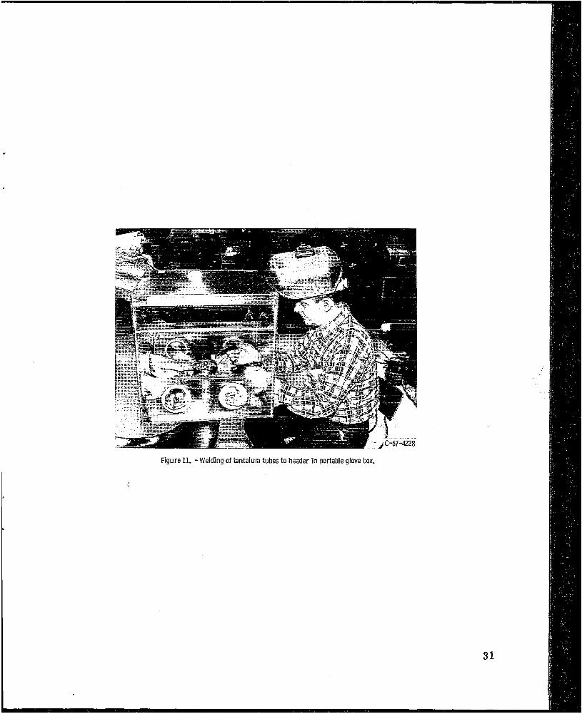
Figure 11. -Welding oftantalum tubes to header in portable glove box.
31
View C - Tantalum- or i f ice -to -t ube-to- header seal weld
/ Tantalum or i f ice block
Stainless- Stainless-steel steel baffle
containment tube Sta in less-steel
,- Stainless-steel
*-Tantalum reducer
I \ L' Reducer I tantalum
/ Tantalum tube-/
Tantalum plug'
/ 0.61 cm (0.25 in. 1
View A - Stainless- steel -tube-to -heade r
L Insu lator vacuum header
View B -Mechanica l joint, tan tal um tube to header
C D- 11032-33 weld
Figure 12. - Details o f header and tube welds (boiler mercu ry inlet).
32

Figure 13. - Stainless-steel header and tube weld. Figure 14. - M e r c u r y in le t subassembly.

Figure 15. -Mercury outlet subassembly.
,- Stainless-steel
r Stainless steel
--
Figure 16. - Electmn-beam weld of stainlesssteel flange to bimetal tube.
34

1 ' Y
C-70-228
Figure 17. - Complete SNAP-8 Ser ia l Number 4 boiler.
35

1 6 0 r 120r
- NaK in le t temperature, K (OF) --- Liquid mercury flow, kg lhr ( Ib lhr)
NaK in let temperature, K OF
0 977 (BOO) n 950 (1250) 0 922 (1200) 0 894 (1150)
(a) NaK flow, 22 200 kilograms per hour (49 OOO (b) NaK flow, 16 780 kilograms per hou r (c) NaK flow, 11 330 kilograms per hour Iblhrl. (37 Mx) IWhrl. (25 Mx) Ibfhr) .
Figure 18. -Total boiler mercury pressure drop as funct ion of independent boiler parameters.

120 -
160 -
100 - 140 -
';i 120- n
N
E, -... z .i 0 L U
L n
NaK in le t temperature, K (OF) --_ Liquid mercury flow, kg lhr (Iblhr)
NaK in let temperature, K (OF)
0 977 (1300) A 950 (1250) 0 922 (1203) 0 894 (1150)
(a) NaK flow, 22 200 kilograms per hou r (49 000 Iblhr). (b) NaK flow, 16 780 kilograms per (c) NaK flow, 11 330 kilograms per hou r hour (37000 Iblhr) . (25 OOO Iblhr).
Figure 19. - Boiler mercury vapor pressure drop as function of boiler independent parameters.
w cn
80 r -
0
NaK in le t temperature, K (OF) --- Liquid mercury flow, kg lh r ( Ib lh r )
NaK in let temperature, K (OF)
0 977 (UOO) A 9% (12%) 0 922 (1200) 0 894 (11%)
5433 (12 OOO)
(a) NaK flow, 22 200 kilograms per h o u r (49 OOO Iblhr) . (b) NaK flow, 16 780 kilograms per h o u r (c) NaK flow, 11 330 kilograms per hour (37 000 Iblhr) . (25 000 Iblhr) .
Figure 20. - Boiler terminal temperature difference as funct ion of boiler independent parameters.

400 -
f . .
250 - NaK inlet temperature, K (OF) --- Liquid mercury flow, kg lh r (Iblhr)
NaK inlet temperature, K (OF)
(a) NaK flow, 22 200 kilograms per hou r (49 OOO (b) NaK flow, 16 780 kilograms per hou r (37 Mx) (c) NaK flow, 11 330 kilograms per lblhr). Iblhr). hou r (25 OOO Ib/hr).
Figure 21. - Boiler pinch point temperature difference as function of boiler independent parameters.
w (D
Overall boi ler pressure drop -,
/ Boil ing pressure drop w i th 0.83 m (2.7 ft) multipassage p lug -,,
ori f ice w i th sharp edge
Liquid pressure drop for 0.127 cm (0.05 in.) diam
-
I I I I I 0 M 40 60 80 100
Percent of design l iqu id mercury flow
Figure 22. - Mercury boi l ing and or i f ice pressure drop as func t ion of mercury flow rate. NaK flow rate, 26 300 kilograms per h o u r (58000 Iblhr); NaK in le t temperature, 929 K (1210° F); mercury flow rate, 6170 kilograms per h o u r (13 600 Iblhr) ; number of mercury tubes, 12; boiler heated length, 6.4 meters (21 R).
40

i
1'
i
-
I I - , I I I 175 I
Nak Inlet temperature, T .: 977 K (1299" F) Mercury flow rate, W : %O kglhr (12 285 Iblhr) NaK flow rate, W : 2$1W kglhr (48 700 Ib lh r l Mercury outlet pFessure, P H b 180.4 Nlcm2 (261.7 psia)
(a) Test condition 1.
w, 170
m 160 165: ' ' , I I , , ,
Tnbp 975 K (1295' F) Wv: 5021 kg lh r (11 070 Iblhr) Wp: 16 870 kglhr (37 xx) Iblhrl
PHC 164.7 Nlcm' (238.9 psia)
(b) Test condition 2.
Wy: 4390 kylhr (9680 Ib lh r l Wp: 12 020 kglhr (26 500 Iblhr)
P H ~ 142.3 N/cm2 (206.4 psia)
IC) Test condition 3.
Wv: 5070 kglhr (11 180 Iblhr) W p 22 OOO kglhr (48 Mo l b lh r )
PH~o: 162.6 N/cm2 (235.8 psia)
(d) Test condition 4.
TnbV 945 K (1241' F) Wv: 4697 kglhr (10 335 Iblhr)
PHb: 150.0 Nlcm2 (217.5 psia)
(e) Test condition 5.
W v 16 780 kglhr (37 OOO Iblhr)
130
0 4 8 12 16 XI 24 28 32 36 40 44 48 Time, sec
TnbV 949 K (12480 F) Wv: 3833 kglhr (84% Iblhr) Wp: 12 250 kglhr (27 OOO Iblhr)
P H ~ : 123.3 Nlcm2 (178.8 psia)
(fl Test condition 6.
Figure 23. - SNAP-8 boiler pressure oscillations (strip-chart recordings).
4 1

T,bv 919 K 11194' F I W,: 4912 kglhr I10 830 Iblhr) Wp: 220Wkglhr148Molblhrl
pHb0: 1520 N l c m 2 i ~ . 4 psial
(gl Test condition 1.
-- 1 l . I , 1
Tnb? 918 K 111920 F I W,: 4291 kglhr 19469 lblhrl Wp: 21 910 kglhr 148 MO lblhrl
pHbO: 134.9 Nlcm2 1195.7 psia)
l h l Test candition 8.
Tnbp 918 K 11199 FI W,: 4320 kglhr 19530 Iblhrl
~Hb0: 134.1 Nlcm'1194.5 psial Wp: 17 OM kglhr (37 600 lblhrl
._ E lil Test condition 9. m N
m " m 2
m
Tnbf 919 K (1194OF) L m
0 m
L
0 - ._ - ._ m
W . 3390 kglhr 17470 Iblhrl W i 12020 kgihr (26 500 lblhrl
PHbo: 106.2 Nlcm2(154.0 psi4 lil Test condition 10
Tnb? 888 K 11139' FI W,: 4140 kglhr 19125 lblhrl
P H 6 126.2 Nlcm2 1183.1 psia)
1kl Test condition 11.
Wp: 22050 kglhr 1486W lblhrl
115 1 10 105
T,bi: 890 K 11147' F) W,: 3670 kglhr 18085 Iblhrl Wp: 169M1kglhr1374CQIblhrl
pHb: 111.5 Nlcm* (161.7 p i a l
IU Test condition 12
$%.; 1 I I i 1 1 I I I 1
12 16 20 24 28 32 36 40 44 48 Time, sec
W,: 2990 kglhr I6590 Iblhrl Wp: 12025 kglhr 126 Mo Iblhrl
P H ~ 91.2 Nl~m~1132.3 psial
Im l Test condition 13.
Figure 23. - Concluded.
T,b? 890 K 11143' FI
42

NaK i n l e t temperature,
K (OF)
0 933 (1220) N 922 (1200)
.g 100r - 70r 911(1180)
M e r c u r y l iquid flow, k g l h r
1- bo00 7000 8000 90W
M e r c u r y l i qu id flow, l b l h r
Figure 24. - Overall boiler m e r c u r y pressure drop var iat ion w i th mercu ry flow rate for revised system state point operation. NaK flow rate, 14 970 ki lograms per h o u r (33 000 Ib lh r ) .
L o) L
NaK in le t temperature,
K (OF)
0 933 (1220) A 922 (1200) 0 911(1180)
3000 3500 4000 M e r c u r y l i qu id flow, k g l h r
_I 4500
u 6OOO 7000 8000 9000
M e r c u r y l i qu id flow, l b l h r
Figure 25. - Boi ler t e rm ina l temperature di f ference var iat ion w i t h m e r c u r y flow rate for revised system state point operation. NaK flow rate, 14 970 ki lograms per h o u r (33 000 Ib lh r ) .
43

. Reactor deadband = 380 r
.- v) * d e V W L 3 v) v) W
L CL
L a,
0 - .- m
100
60 8't 40
d e m
L al
0 M
- .-
70 r
40
n n n n
I 940
_ _ 1 I 900 9 10 920 930
Boi ler NaK in le t temperature, K
L-U 1 I . . I I I 1160 1170 1180 1190 1200 1210 1220 1230
Boi ler NaK in le t temperature, OF
Figure 26. - Response of system variables to reactor deadband temperature var ia- t i o n s for revised system state point operation.
44

- Reactor deadband
Boi ler NaK in le t temperature, K
1 1 1 1 1 1 1 1160 1170 1180 1190 1200 1210 1220 1230 1240
Boi ler NaK in le t temperature, OF
F igu re 26. - Concluded.
45
46
1350-
1300
1250-
1200
1150
1100-
1050
1CN-
-
-
-
-
1 vj
t-PlU9-t- Wi re tu rbu la to r ~
1 3 5 0 ,F NaK temperature (test data)
1350
1300
1250
1200
1150
1100
1050
1000
950
900
CI
850
-
-
-
-
-
-
-
-
M e r c u r y temperature
i
- 4 5 0 1 2 0 0 1 I I I
m O //- 2 4 I 6 8 10 12 LL 0 x Distance f r o m mercu ry boiler inlet, m
r M e r c u r y p r e s s u r e i
1 (analytical)
---0 850
Distance from mercu ry boiler inlet, m
I.. 1 1 I 1 . I 0 8 16 24
Distance from mercu ry boiler inlet, ft
(b) Serial Number 4 boiler.
1
F igu re 27. - Comparison of Ser ia l Number 2 and Ser ia l Number 4 boi lers a t nomina l system operating conditions. Refractory boiler test data and analyt ical curves.
NASA-Langley, 1971 - 3 E-6149

NATIONAL AERONAUTICS AND SPACE ADMINISTRAI ION
WASHINGTON, D. C. 20546
OFFICIAL BUSINESS PENALTY FOR PRIVATE USE $300
FIRST CLASS MAIL
POSTAGE AND FEES PAID NATIONAL AERONAUTICS A N D
SPACE ADMINISTRATION
004 001 C 1 U DEPT OF THE AIR FORCE A F SYSTEMS COMMAND AF WEhPONS LAB (WLOL) .
BTTN: E LOU BOWRAN, CHIEF TECH LIBRARY K I R T L A N D AFB NM 87117 "
0 3 710806 S00903DS
POSTMASTER: If Undeliverable (Section 158 Postal Manual ) Do Not Return
~.~
'The aeronautical and space activities of the United States shall be conducted so as t o contribute . . . t o the expansion of hunzan knowl- edge of phenomena in the at~tiosphere and space. The Administration shall provide for the widest practicable and appropriate dissemination of inforniation concerning its actiflities and the restilts thereof."
-NATIONAL AERONAUTICS AND SPACE ACT OF 1958
NASA SCIENTIFIC AND TECHNICAL PUBLICATIONS
TECHNICAL REPORTS: Scientific and technical information considered important, complete, and a lasting contribution to existing knowledge.
TECHNICAL NOTES: Information less broad in scope but nevertheless of importance as a contribution to existing knowledge.
TECHNICAL MEMORANDUMS: Information receiving limited distribution because of preliminary data, security classifica- tion, or other reasons.
TECHNICAL TRANSLATIONS: Information published in a foreign language considered to merit NASA distribution in English.
SPECIAL PUBLICATIONS: Information derived from or of value to NASA activities. Publications include conference proceedings, monographs, data compilations, handbooks, sotircebooks, and special bibliographies.
TECHNOLOGY UTILIZATION PUBLICATIONS: Information on technology used by NASA that may be of particular interest in commercial and other non-aerospace applications. Publications include Tech Briefs, Technology Utilization Reports and Technology Surveys.
CONTRACTOR REPORTS: Scientific and technical information generated under a NASA contract or grant and considered an important contribution to existing knowledge.
Details on the availability of these publications may be obtained from:
SCI ENTl F IC AND TECHNICAL IN FORMATION OF FlCE
NATIONAL AERONAUTICS AND SPACE ADMINISTRATION Washington, D.C. PO546