Embed Size (px)
Citation preview
www.Fisher.com
D10
0025
X01
2
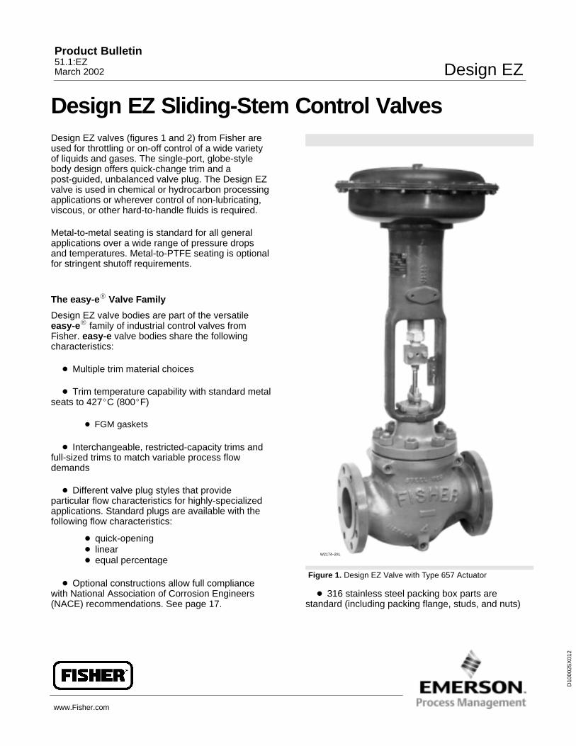
Design EZ Sliding-Stem Control ValvesDesign EZ valves (figures 1 and 2) from Fisher areused for throttling or on-off control of a wide varietyof liquids and gases. The single-port, globe-stylebody design offers quick-change trim and apost-guided, unbalanced valve plug. The Design EZvalve is used in chemical or hydrocarbon processingapplications or wherever control of non-lubricating,viscous, or other hard-to-handle fluids is required.
Metal-to-metal seating is standard for all generalapplications over a wide range of pressure dropsand temperatures. Metal-to-PTFE seating is optionalfor stringent shutoff requirements.
The easy-e� Valve Family
Design EZ valve bodies are part of the versatileeasy-e� family of industrial control valves fromFisher. easy-e valve bodies share the followingcharacteristics:
� Multiple trim material choices
� Trim temperature capability with standard metalseats to 427�C (800�F)
� FGM gaskets
� Interchangeable, restricted-capacity trims andfull-sized trims to match variable process flowdemands
� Different valve plug styles that provideparticular flow characteristics for highly-specializedapplications. Standard plugs are available with thefollowing flow characteristics:
� quick-opening� linear� equal percentage
� Optional constructions allow full compliancewith National Association of Corrosion Engineers(NACE) recommendations. See page 17.
Figure 1. Design EZ Valve with Type 657 Actuator
W2174–2/IL
� 316 stainless steel packing box parts arestandard (including packing flange, studs, and nuts)
Product Bulletin51.1:EZMarch 2002 Design EZ

Design EZProduct Bulletin
51.1:EZMarch 2002
2
Contents
Features 2. . . . . . . . . . . . . . . . . . . . . . . . . . . . . . . . . .
ENVIRO-SEAL� and HIGH-SEAL�Packing Systems 3. . . . . . . . . . . . . . . . . . . . . . .
ENVIRO-SEAL and HIGH-SEALFeatures 4. . . . . . . . . . . . . . . . . . . . . . . . . . . . . . . . . .
Micro-Flute� Valve Plugs forMinimum Leakage 6. . . . . . . . . . . . . . . . . . . . . .
Class VI Shutoff Capabilities 7. . . . . . . . . .
NACE Standard MR0175Compliance 16. . . . . . . . . . . . . . . . . . . . . . . . . . . . .
TablesClass VI Shutoff 6. . . . . . . . . . . . . . . . . . . . . . . . . . . Class VI Trim Materials 6. . . . . . . . . . . . . . . . . . . . . Material Cross Reference 7. . . . . . . . . . . . . . . . . . . Typical Combinations of Metal Trim Parts 8. . . . . Construction Materials & Temperature Limits 9. . Valve Body/Trim Temperature Capabilities 10. . . Bonnet Selection Guidelines 12. . . . . . . . . . . . . . . Maximum Allowable Pressure Drops 12. . . . . . . . Gasket Selection Guidelines 13. . . . . . . . . . . . . . . Maximum Allowable Pressure Drops for
Gasket Materials 14. . . . . . . . . . . . . . . . . . . . . . . Maximum Flow Coefficients 15. . . . . . . . . . . . . . . . Port Diameters, Valve Plug Travel, and
Stem and Yoke Boss Diameters 15. . . . . . . . . . Typical Combinations of Trim Parts (NACE) 15. . Bolting Materials and Temperature Limits
for Bolting Compliance (NACE) 16. . . . . . . . . . .
Ordering Information 17. . . . . . . . . . . . . . . . . .
Dimensions 17. . . . . . . . . . . . . . . . . . . . . . . . . . . . .
Specifications 19. . . . . . . . . . . . . . . . . . . . . . . . . .
ENVIRO-SEAL Packing SystemSpecifications 20. . . . . . . . . . . . . . . . . . . . . . . . . .
Features� Trim Designed for Stability—Post guiding
provides valve plug stability with less chance of asticking valve plug due to non-lubricating or stickyprocess fluids or build-up of entrained solids. Postguiding stabilizes the valve plug at all points in itstravel range to reduce vibration, mechanical noise,and trim wear.
� Performance+ Seat Ring—Flow-straightening,vaned seat ring is available in full port and firstreduction port sizes. It offers superior open- andclosed-loop performance and may be used as adirect replacement for the non-vaned seat ring.Fisher recommends that the Performance+ seat ringbe used for non-viscous, flow-up, liquid applications.
� Compliance with the Clean Air Act—OptionalENVIRO-SEAL packing systems (figure 4) provide asuperior stem seal to prevent the loss of processfluid. The ENVIRO-SEAL packing systems featurePTFE, graphite, or duplex packing with live-loadingfor reduced packing maintenance.
� Reliability—The process fluid flows throughthe trim, flushing away solid deposits above andbelow the guide bushing, thus reducing thepossibility of a sticking valve plug.
� Easy Maintenance—Quick-change trim, with aclamped-in seat ring, reduces the disassembly time.The valve body can stay in the pipeline duringremoval of trim parts for inspection or maintenance.
� Application Flexibility—Low-flowrequirements can be satisfied with standardrestricted-capacity trim or with Micro-Form�,Micro-Flute�, or Micro-Flow� valve plugs. If flowrequirements change, the valve can be converted tofull-sized trim.
� Economy—Streamlined flow passages providegreater capacities than most globe valves of thesame line size.
� Compliance with EuropeanStandards—Valves are available with dimensionsspecified by EN/DIN standards. See figure 8.
� Sour Gas Service Capability—Special trimand bolting materials are available for applicationshandling sour fluids and gases. These constructionscomply with the recommendations of NationalAssociation of Corrosion Engineers (NACE)MR0175. Because of the care exercised by Fisher inprocurement and manufacturing, additional testing

Design EZProduct Bulletin51.1:EZMarch 2002
3
Figure 2. Design EZ Sectional
35A7592-EW7027-2 / IL
and documentation to assure compliance with theNACE standard MR0175 is not required, in mostcases.
ENVIRO-SEAL, HIGH-SEALPacking SystemsThe ENVIRO-SEAL and HIGH-SEAL packingsystems from Fisher offer exceptional sealingcapabilities. These systems easily install in yourexisting valves or can be purchased with newvalves. These systems help you seal your process toconserve valuable process fluid. The longer-life andreliability of these systems also reduce yourmaintenance cost and downtime.
For applications requiring compliance withenvironmental protection regulations, Fisher offersthe unique ENVIRO-SEAL packing system (figure 4)
and, for hazardous service, the ENVIRO-SEALbellows seal system (figure 3). The patentedemission control packing system keeps emissionconcentrations below the EPA 500 ppm requirement.
For a superior stem seal in applications that are notenvironmentally-sensitive, Fisher offers theHIGH-SEAL graphite packing system (figure 4). TheHIGH-SEAL packing system provides superiorsealing at pressure/temperature ratings beyondENVIRO-SEAL limits. ENVIRO-SEAL systems mayalso be applied for superior stem sealing in higherpressure/temperature applications not requiring EPAcompliance.
ENVIRO-SEAL packing systems, available withPTFE, graphite, or duplex packing, and theHIGH-SEAL graphite packing system featurelive-loading and unique packing-ring arrangementsfor long-term, consistent sealing performance.

Design EZProduct Bulletin
51.1:EZMarch 2002
4
ENVIRO-SEAL, HIGH-SEAL Features
� Excellent Sealing Capabilities—The patentedpacking system provides excellent sealing, guiding,and transmission of loading force. The superiorsealing of the ENVIRO-SEAL system can controlemissions to below the EPA (EnvironmentalProtection Agency) minimum of 500 ppm (parts permillion).
� Improved Service Life—ENVIRO-SEAL andHIGH-SEAL system design, very smooth stemsurface, and live-loading combine to give you longerservice with very low maintenance. The externallive-loading provides a constant load over the life ofthe packing material, which greatly reduces oreliminates your need for packing box adjustment andmaintenance.
� Easy Installation in Existing Valves—Allparts needed to install the systems in existing valvesare available in a convenient kit.
� Adaptable to ManyApplications—ENVIRO-SEAL systems areavailable with PTFE or graphite packing for 9.5through 31.8 mm (3/8 through 1-1/4 inch) diametervalve stems. HIGH-SEAL systems with graphitepacking are available for 9.5 through 50.8 mm (3/8through 2-inch) diameter valve stems. StandardENVIRO-SEAL packing systems can be used invacuum service with packing rings in standardorientation. It is not necessary to reverse theENVIRO-SEAL PTFE packing rings.
Figure 3. Design EZ Valve with ENVIRO-SEAL Bellows Seal Bonnet
W5800-2*A/IL
PACKING
ANTI-ROTATORPIN
PURGE-MONITORINGCONNECTION
PROTECTIVESHROUD
BELLOWS
VALVE PLUGCONNECTION
VALVE PLUG

Design EZProduct Bulletin51.1:EZMarch 2002
5
Figure 4. ENVIRO-SEAL and HIGH-SEAL Packing Systems
����������� �����������������
�����������������
W5803–3 / IL
SPRINGS
ANTI–EXTRUSIONRING
LANTERNRING
PACKINGBOXSTUDS
PACKINGRING
VALVEBONNET
����������� �����������������
���������������
SPRING
PACKING
PACKINGBOXSTUD
FOLLOWER
W5801–3 / IL
�����������������������������
�������������������
SPRINGS
FOLLOWER
PACKINGBOXSTUD
PACKING
VALVEBONNET
W5805–5 / IL
����������� �����������������
�������������������
W7018 / IL
Design EZProduct Bulletin
51.1:EZMarch 2002
6
Table 1. Class VI Shutoff AvailabilityType Port Size, Inches Seat Minimum Seat Load
EZ � 4 Metal 300 lbs/lineal inch
Table 2. Class VI Trim Materials
CAGE/SEAT RING TRIM TEMPERATURE LIMITTYPE
CAGE/SEAT RINGRETAINER VALVE PLUG SEAT RING
�C �F
EZ S31600 (316 SST)S31600/CoCr-A (alloy
6) seat w/ standardbeveled seat
S31600 w/ radiusedseat (special design)
Not a limiting factor Not a limiting factor
EZ S31600S31600/CoCr-A seat
and guide w/ standardbeveled seat
S31600 w/ radiusedseat (special design)
Not a limiting factor Not a limiting factor
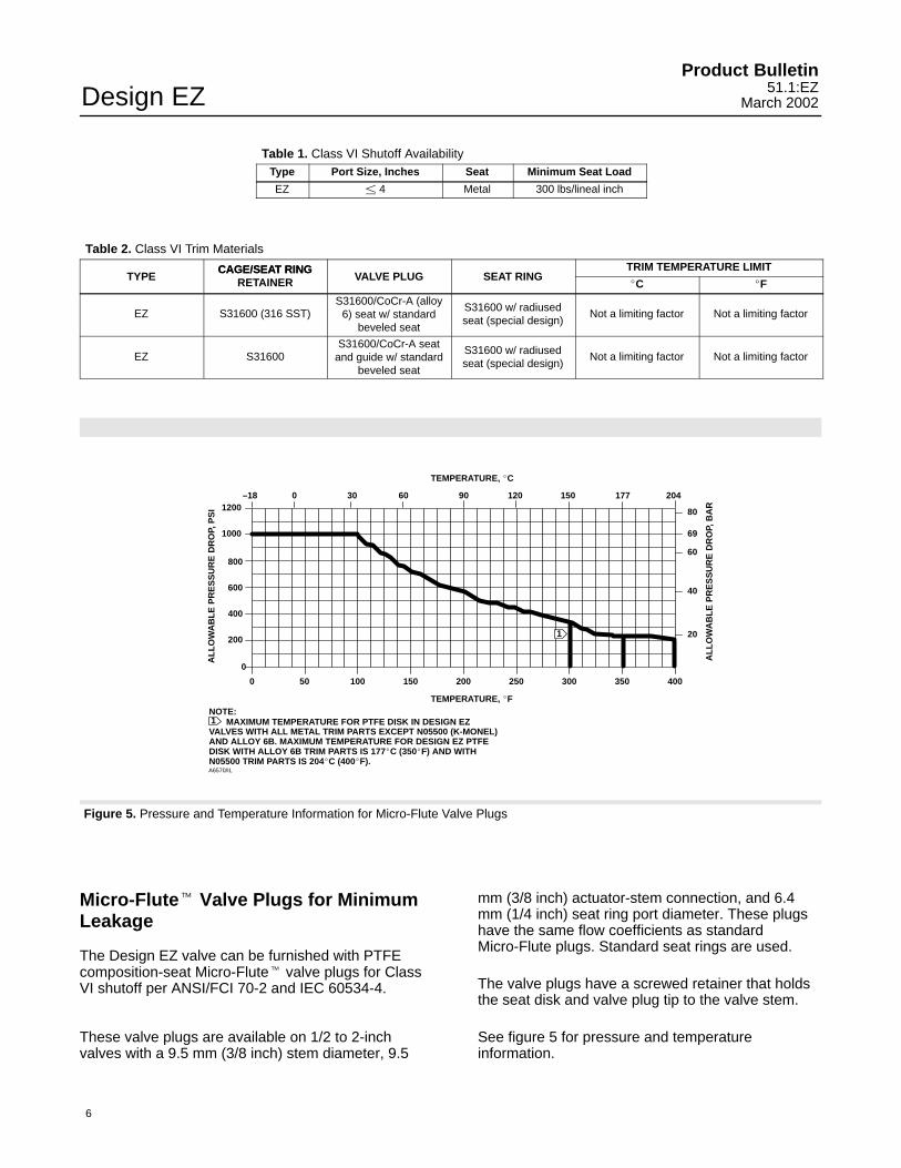
Figure 5. Pressure and Temperature Information for Micro-Flute Valve Plugs
MAXIMUM TEMPERATURE FOR PTFE DISK IN DESIGN EZVALVES WITH ALL METAL TRIM PARTS EXCEPT N05500 (K-MONEL)AND ALLOY 6B. MAXIMUM TEMPERATURE FOR DESIGN EZ PTFEDISK WITH ALLOY 6B TRIM PARTS IS 177�C (350�F) AND WITHN05500 TRIM PARTS IS 204�C (400�F).
0 50 100 150 200 250 300 350 400
0
200
400
600
800
1000
1200
20
40
60
69
80
–18 0 30 60 90 120 150 177 204
TEMPERATURE, �C
TEMPERATURE, �F
1NOTE:
AL
LO
WA
BL
E P
RE
SS
UR
E D
RO
P, P
SI
AL
LO
WA
BL
E P
RE
SS
UR
E D
RO
P, B
AR
1
A6570/IL
Micro-Flute� Valve Plugs for MinimumLeakage
The Design EZ valve can be furnished with PTFEcomposition-seat Micro-Flute� valve plugs for ClassVI shutoff per ANSI/FCI 70-2 and IEC 60534-4.
These valve plugs are available on 1/2 to 2-inchvalves with a 9.5 mm (3/8 inch) stem diameter, 9.5
mm (3/8 inch) actuator-stem connection, and 6.4mm (1/4 inch) seat ring port diameter. These plugshave the same flow coefficients as standardMicro-Flute plugs. Standard seat rings are used.
The valve plugs have a screwed retainer that holdsthe seat disk and valve plug tip to the valve stem.
See figure 5 for pressure and temperatureinformation.

Design EZProduct Bulletin51.1:EZMarch 2002
7
Table 3. Material Cross Reference
Standard Designation Common/TradenameOther Designation
Standard Designation Common/TradenameOther Designation
CB7Cu-1CF8MCoCr-AWC9N04400N05500M35-1
17-4 PH Stainless Steel316 Stainless SteelAlloy 6 HardfacingChrome-Moly SteelMonel 400K-Monel, Alloy K500Monel
R30006S17400S31600S31603S41600WCCAlloy 6B
Alloy 6, Cast17-4 PH Stainless Steel316 Stainless Steel316L Stainless Steel416 Stainless SteelWCC SteelAlloy 6, Wrought
Figure 6. Typical PTFE Seat Trim
2
1
NOTES:ALSO APPLIES TO TRIMS 101C, 127C,
137C, 151C, 153C, 154C, AND 158C.ALSO APPLIES TO TRIMS 104C, 128C,
129C, 139C, 152C, 155C, 156C, AND 157C.
1
2
A6415/IL
PTFE SEATING WITHALL VALVE BODY MATERIALS
(–29�C [–20�F] WITH WCCVALVE BODY)
Class VI Shutoff CapabilitiesDesign EZ valves with metal seat constructions canprovide ANSI/FCI Class VI shutoff capabilities. Seetables 1 and 2.

Design EZProduct Bulletin
51.1:EZMarch 2002
8
Table 4. Typical Combinations of Metal Trim Parts for Equal Percentage (Including Micro-Form), Linear, and Quick Opening Valve Plugs
TrimDesignation
ValvePlug
ValveStem
SeatRing
Seat RingRetainer
Disk Seat andRetainer for
Optional PTFE-SeatConstruction
GuideBushing
101(1)S41600(416 stainless steel)hardened
S31600(316 stainless steel)
S41600hardened
CB7Cu-1(17-4 PHstainless steel)
S41600S17400(17-4 PHstainless steel)
104 S31600(316 stainless steel)
S31600 S31600 CB7Cu-1 S31600 S17400
120 N05500 (K-Monel) N05500 N05500 M35-1 (Monel) N05500 N05500
127S31600 w/CoCr-A(alloy 6)seat & guide
S31600 S31600w/CoCr-A seat
CF8M(316 stainless steel)
- - - Alloy 6B
128 S31600w/CoCr-A seat
S31600 S31600w/CoCr-A seat
CF8M - - - Alloy 6B
129(2) S31600 S31600 S31600 CF8M S31600 Alloy 6B
137S31600w/CoCr-Aseat & guide
S31600 S31600w/CoCr-A seat
CB7Cu-1 - - - S17400
139 S31600w/CoCr-A seat
S31600 S31600w/CoCr-A seat
CB7Cu-1 - - - S17400
1. Standard trim for cast iron, WCC, and WC9 valve bodies, except Micro-Flow and Micro-Flute.2. Standard trim for CF8M valve body.
Table 5. Typical Combinations of Metal Trim Parts for Micro-Flute and Micro-Flow Valve Plugs(These Constructions Do Not Use Guide Bushing)
TrimDesignation
ValvePlug
ValveStem
SeatRing
Seat RingRetainer
Disk Seat andRetainer for
Optional PTFE-SeatConstruction(1)
151S41600(416 stainless steel)hardened
S31600(316 stainless steel)
S41600 hardened CB7Cu-1(17-4 PH stainless steel)
- - -
152(2)
S31600(316 stainless steel)w/CoCr-A (alloy 6)seat, R30006 tip
S31600 S31600 CB7Cu-1 S31600
153 N05500 (K-Monel) N05500 N05500 M35-1 (Monel) N05500
154 S31600 w/CoCr-Aseat, R30006 tip
S31600 S31600w/CoCr-A seat & bore
CF8M(316 stainless steel)
- - -
155 S31600 w/CoCr-Aseat, R30006 tip
S31600 S31600w/CoCr-A seat(3) CF8M - - -
156 S31600 w/CoCr-Aseat, R30006 tip
S31600 S31600 CF8M S31600
157 S31600 w/CoCr-Aseat, R30006 tip
S31600 S31600w/CoCr-A seat(3) CB7Cu-1 - - -
158 S31600 w/CoCr-Aseat, R30006 tip
S31600 S31600w/CoCr-A seat & bore
CB7Cu-1 - - -
1. Micro-Flute constructions.2. Standard trim for Micro-Flow and Micro-Flute constructions in cast iron, WCC, CF8M, and WC9 valve bodies.3. Micro-Flute and Micro-Flow valve plugs have a CoCr-A seat and R30006 tip, but are not recommended for erosive service without the additional use of CoCr-A on the seat and boreof the seat ring.

Design EZProduct Bulletin51.1:EZMarch 2002
9
Table 6. Construction Materials and Temperature Limits
PART MATERIALTEMPERATURECAPABILITIESPART MATERIAL
�C �F
Cast iron valve body Cap screws Steel SAE Grade 5 –29 232(1) –20 450(1)Body-to-
Studs Steel SA-193-B7bonnetbolting.
WCC steel bodyNuts Steel SA-194-2H (lubricated)
–29 427 –20 800bolting.See table Studs Steel SA-193-B7 (standard)16 for Nuts Steel SA-194-2H (standard)
–48 427 –55 800NACEbolting CF8M (316 stainless Studs 304 stainless steel SA-320-B8boltingmaterials
CF8M (316 stainlesssteel) body Nuts 304 stainless steel SA-194-8
–198 38 –325 100
and Studs 316 stainless steel SA-193-B8M (strain hardened)temperatures
Nuts 316 stainless steel SA-194-8M (lubricated)–198 427 –325 800
Seat disk (optional) PTFE –73 204 –100 400
S31600 (316 stainless steel)/graphite(2) –198 593(4) –325 1100(4)
Bonnet and seat ring gasketPTFE-coated N04400 (Monel) (optional for trim 120) –73 149 –100 300
N04400/composition (standard for trims 120 & 153) –73 232 –100 450
Spiral wound gaskets N04400/PTFE (optional for trims 120 & 153) –73 149 –100 300Spiral wound gasketsN06600 (Inconel)/graphite (FGM) standard –198 593(4) –325 1100(4)
S31600 These materials notShim
N04400 (standard for trims 120 & 153)These materials not
limiting factors
Packing flange studs and nuts whenused with standard bonnet
S31600 –198 593 –325 1100
PTFE V-ring –40 232 –40 450Packing (temperatures shown are PTFE/composition –73 232 –100 450material temperature capabilities).
Graphite ribbon/filament –198 538(5) –325 1000(5)See table 8 for proper bonnet selection
Graphite ribbon for high-temperature oxidizing service –198 649 –325 1200
S31600(2) –198 593 –325 1100Packing follower
N04400 (optional for trims 120 & 153) –198 482 –325 900
Packing spring S31600 –198 593 –325 1100
S31600(3) –198 593 –325 1100Lantern ring (for double packing)
N04400 (standard for trims 120 & 153) –198 482 –325 900
S31600(3) –198 593 –325 1100Packing box ring
N04400 –198 482 –325 9001. Temperature limit for bodies with screwed end connections is 208�C (406�F).2. Standard for all trim.3. Standard for all trim except for trim 120 and 153.4. Except 427�C (800�F) for oxidizing service.5. Except 371�C (700�F) for oxidizing service.

Design EZProduct Bulletin
51.1:EZMarch 2002
10
Table 7. Valve Body/Trim Temperature Capabilities for Metal Trim PartsTEMPERATURE CAPABILITIES
VALVE BODYMATERIAL
VALVE BODY SIZE,INCHES
Trim for Equal Percentage(Including Micro-Form), Linear,and Quick Opening Valve Plugs
Trim for Micro-Flute andMicro-Flow Valve Plugs
MATERIAL INCHES
Trim �C �F Trim �C �FTrimDesignation Min Max Min Max
TrimDesignation Min Max Min Max
101 –29 232 –20 450 151 –29 232 –20 450
120 –73 232 –100 450 153 –73 232 –100 450
1/2, 3/4, 1, 1-1/2, or 2 87, 127, 137 –73 232 –100 450 154, 158 –73 232 –100 4501/2, 3/4, 1, 1-1/2, or 285, 86, 128, 129 –73 232(1) –100 450(1) - - - - - - - - - - - - - - -
139, 104 –73 232(1) –100 450(1) 152, 155, 156, 157 –73 149 –100 300
Cast iron 101 –29 232 –20 450 - - - - - - - - - - - - - - -Cast iron104, 139 –73 232(1) –100 450(1) - - - - - - - - - - - - - - -
120 –73 232 –100 450 - - - - - - - - - - - - - - -3 or 4
87, 127 –73 232 –100 450 - - - - - - - - - - - - - - -
85, 86, 128, 129 –73 232(1) –100 450(1) - - - - - - - - - - - - - - -
137 –73 232 –100 450 - - - - - - - - - - - - - - -
101 –29 427 –20 800 151 –29 316 –20 600
104, 139 –29 427(1) –20 800(1) 152, 157 –29 149 –20 300
120 –29 316 –20 600 153 –29 316 –20 600
1/2, 3/4, 1, 1-1/2, or 2 87, 127 –29 260 –20 500 154 –29 427 –20 8001/2, 3/4, 1, 1-1/2, or 286, 128 –29 260(1) –20 500(1) - - - - - - - - - - - - - - -
85, 129 –29 260(1) –20 500(1) 156 –29 149 –20 300
137 –29 427 –20 800 158 –29 427 –20 800
101 –29 427 –20 800 - - - - - - - - - - - - - - -
104, 139 –29 371(1) –20 700(1) - - - - - - - - - - - - - - -
WCC steel 120 –29 316(1) –20 600(1) - - - - - - - - - - - - - - -WCC steel3
87, 127 –29 371 –20 700 - - - - - - - - - - - - - - -
85, 86, 128, 129 –29 371(1) –20 700(1) - - - - - - - - - - - - - - -
137 –29 371 –20 700 - - - - - - - - - - - - - - -
101 –29 427 –20 800 - - - - - - - - - - - - - - -
104, 139 –29 371(1) –20 700(1) - - - - - - - - - - - - - - -
120 –29 316(1) –20 600(1) - - - - - - - - - - - - - - -4
87, 127 –29 338 –20 640 - - - - - - - - - - - - - - -
85, 86, 128, 129 –29 338(1) –20 640(1) - - - - - - - - - - - - - - -
137 –29 371 –20 700 - - - - - - - - - - - - - - -
101 –29 354 –20 670 151 –29 316 –20 600
104 –101 371(1) –150 700(1) 152 –101 149 –150 300
120 –198 316 –325 600 153 –198 316 –325 600
87, 127 –198 260 –325 500 154 –198 593 –325 11001/2, 3/4, 1, or 1-1/2
86, 128 –198 260(1) –325 500(1) - - - - - - - - - - - - - - -
85, 129 –198 260(1) –325 500(1) 156 –198 149 –325 300
137 –101 371 –150 700 158 –101 371 –150 700
CF8M 139 –101 371(1) –150 700(1) 157 –101 149 –150 300CF8M(316 stainless steel) 101 –29 288 –20 550 151 –29 288 –20 550
104 –101 299(1) –150 570(1) 152 –101 149 –150 300
120 –198 316 –325 600 153 –198 316 –325 600
87, 127 –198 260 –325 500 154 –198 593 –325 11002
86, 128 –198 260(1) –325 500(1) - - - - - - - - - - - - - - -
85, 129 –198 260(1) –325 500(1) 156 –198 149 –325 300
137 –101 299 –150 570 158 –101 299 –150 570
139 –101 299(1) –150 570(1) 157 –101 149 –150 300
- Continued -

Design EZProduct Bulletin51.1:EZMarch 2002
11
Table 7. Valve Body/Trim Temperature Capabilities for Metal Trim Parts (Continued)TEMPERATURE CAPABILITIES
VALVE BODYMATERIAL
VALVE BODY SIZE,INCHES
Trim for Equal Percentage(Including Micro-Form), Linear,and Quick Opening Valve Plugs
Trim for Micro-Flute andMicro-Flow Valve Plugs
MATERIAL INCHES
Trim �C �F Trim �C �FTrimDesignation Min Max Min Max
TrimDesignation Min Min Min Max
101 –29 216 –20 420 - - - - - - - - - - - - - - -
104, 139 –101 227(1) –150 440(1) - - - - - - - - - - - - - - -
120 –198 316 –325 600 - - - - - - - - - - - - - - -3
87, 127 –198 377 –325 700 - - - - - - - - - - - - - - -
85, 86, 128, 129 –198 377(1) –325 700(1) - - - - - - - - - - - - - - -
CF8M 137 –101 227 –150 440 - - - - - - - - - - - - - - -CF8M(316 stainless steel) 101 –29 177 –20 350 - - - - - - - - - - - - - - -
104, 139 –101 182(1) –100 360(1) - - - - - - - - - - - - - - -
120 –198 316 –100 600 - - - - - - - - - - - - - - -4
87, 127 –198 371 –100 700 - - - - - - - - - - - - - - -
85, 86, 128, 129 –198 371(1) –100 700(1) - - - - - - - - - - - - - - -
137 –101 182 –100 360 - - - - - - - - - - - - - - -
101 –29 427 –20 800 151 –29 –29 –20 600
104 –29 427(1) –20 800(1) 152 –29 –29 –20 300
120 –29 316 –20 600 153 –29 –29 –20 600
87, 127 –29 260 –20 500 154 –29 –29 –20 1050(2)1/2, 3/4, 1, 1-1/2, or 2
86, 128 –29 260(1) –20 500(1) - - - - - - - - - - - - - - -
85, 129 –29 260(1) –20 500(1) 156 –29 –29 –20 300
137 –29 427 –20 800 158 –29 –29 –20 800(1)
139 –29 427(1) –20 800(1) 157 –29 –29 –20 300
101 –29 427 –20 800 - - - - - - - - - - - - - - -
WC9 chrome moly 104, 139 –29 371(1) –20 700(1) - - - - - - - - - - - - - - -WC9 chrome molysteel 120 –29 316 –20 600 - - - - - - - - - - - - - - -
387, 127 –29 343 –20 650 - - - - - - - - - - - - - - -
85, 86, 128, 129 –29 343(1) –20 650(1) - - - - - - - - - - - - - - -
137 –29 371 –20 700 - - - - - - - - - - - - - - -
101 –29 427 –20 800 - - - - - - - - - - - - - - -
104, 139 –29 371(1) –20 700(1) - - - - - - - - - - - - - - -
120 –29 316 –20 600 - - - - - - - - - - - - - - -4
87, 127 –29 316 –20 450 - - - - - - - - - - - - - - -
85, 86, 128, 129 –29 232(1) –20 450(1) - - - - - - - - - - - - - - -
137 –29 371 –20 700 - - - - - - - - - - - - - - -1. With non-lubricating fluids, temperature is limited to 149�C (300�F).2. For 2-inch valve body, maximum temperature is 466�C (870�F).

Design EZProduct Bulletin
51.1:EZMarch 2002
12
Table 8. Bonnet Selection GuidelinesIN-BODY PROCESS TEMPERATURE LIMITS(1)
BONNET STYLE PACKING MATERIAL�C �F
Plain:� Standard for 1/2-, 3/4-, 1-, and 1-1/2 inch valves with 2-1/8 inch yoke
PTFE V-ring –18 to 232 0 to 4501/2 inch valves with 2-1/8 inch yokeboss diameter� Standard for 2-, 3-, and 4-inchvalves with 2-13/16 inch yoke boss
PTFE/Composition –18 to 232 0 to 450valves with 2-13/16 inch yoke bossdiameter� Optional for 2-, 3-, and 4-inchvalves with 3-9/16 inch yoke bossdiameter
Graphite ribbon/filament 0 to maximum shownin table 6
0 to maximum shownin table 6
Style 1 Cast Extension: PTFE V-ringStyle 1 Cast Extension:� Optional for all valve sizes. PTFE/Composition
–18 to 232 0 to 450�
Check yoke boss diameter Graphite ribbon/filament –46 to –18 and above 232 –50 to 0 and above 450
Style 2 Cast Extension: PTFE V-ringStyle 2 Cast Extension:� Optional for all valve sizes. PTFE/Composition
–18 to 232 0 to 450�
Check yoke boss diameter Graphite ribbon/filament –101 to –18 and above 232 –150 to 0 and above 450
PTFE For exceptional stem sealing capabilities. SeeENVIRO-SEAL bellows seal bonnet
GraphiteBulletin 59.1:070, ENVIRO-SEAL Bellows SealBonnets, for pressure/temperature ratings.
1. These in-body process temperatures assume an outside, ambient temperature of 21�C (70�F). When using any packing at low process temperatures, a cast extension bonnet mayhave to be used to prevent packing damage which could result from the formation of valve stem frost.
Table 9. Maximum Allowable Pressure Drops per Trim Designation for Equal Percentage(Including Micro-Form), Linear, and Quick Opening Valve Plugs
TRIMDESIGNATION
VALVEPLUG
VALVESTEM
SEATRING
SEAT RINGRETAINER
GUIDEBUSHING
SHUTOFFPRESSURE
DROP
FLOWINGPRESSURE
DROPDESIGNATION PLUG STEM RING RETAINER BUSHINGBar Psig Bar Psig
101S41600(416 stainless steel)hardened
S31600(316 stainless steel)
S41600hardened
CB7Cu-1(17-4 PHstainless steel)
S17400(17-4 PHstainless steel)
103 1500 103 1500
104 S31600(316 stainless steel)
S31600 S31600 CB7Cu-1 S17400 21 300 103 1500
120 N05500 (K-Monel) N05500 N05500 M35-1 (Monel) N05500 55 800 103 1500
87, 127S31600 w/CoCr-A(alloy 6)seat & guide
S31600 S31600w/CoCr-A seat
CF8M(316 stainless steel)
Alloy 6B 103 1500 103 1500
86, 128 S31600w/CoCr-A seat
S31600 S31600w/CoCr-A seat
CF8M Alloy 6B 103 1500 103 1500
85, 129 S31600 S31600 S31600 CF8M Alloy 6B 21 300 103 1500
137S31600w/CoCr-Aseat & guide
S31600 S31600w/CoCr-A seat
CB7Cu-1 S17400 103 1500 103 1500
139 S31600w/CoCr-A seat
S31600 S31600w/CoCr-A seat
CB7Cu-1 S17400 103 1500 103 1500

Design EZProduct Bulletin51.1:EZMarch 2002
13
Table 10. Maximum Allowable Pressure Drops per Trim Designation for Micro-Flute and Micro-Flow Valve Plugs
TRIMDESIGNATION
VALVEPLUG
VALVESTEM
SEATRING
SEAT RINGRETAINER
SHUTOFFPRESSURE
DROP
FLOWINGPRESSURE
DROPDESIGNATION PLUG STEM RING RETAINERBar Psig Bar Psig
151S41600(416 stainless steel)hardened
S31600(316 stainless steel)
S41600 hardened CB7Cu-1(17-4 PH stainless steel)
103 1500 103 1500
152
S31600(316 stainless steel)w/CoCr-A (alloy 6)seat, R30006 tip
S31600 S31600 CB7Cu-1 21 300 103 1500
153 N05500 (K-Monel) N05500 N05500 M35-1 (Monel) 55 800 103 1500
87, 154 S31600 w/CoCr-Aseat, R30006 tip
S31600 S31600w/CoCr-A seat & bore
CF8M(316 stainless steel)
103 1500 103 1500
86, 155 S31600 w/CoCr-Aseat, R30006 tip
S31600 S31600w/CoCr-A seat
CF8M 103 1500 103 1500
85, 156 S31600 w/CoCr-Aseat, R30006 tip
S31600 S31600 CF8M 21 300 103 1500
157 S31600 w/CoCr-Aseat, R30006 tip
S31600 S31600w/CoCr-A seat
CB7Cu-1 103 1500 103 1500
158 S31600 w/CoCr-Aseat, R30006 tip
S31600 S31600w/CoCr-A seat & bore
CB7Cu-1 103 1500 103 1500
Table 11. Gasket Selection Guidelines(1)
Gasket Set Seat Ring Gasket Bonnet Gasket SpiralWound Gasket
Shim TemperatureCapabilities
2(2) 316 SST/graphiteflat sheet
316 SST/graphiteflat sheet
N06600 (Inconel)/graphite(3) S31600 –198 to 593�C(4)
(–325 to 1100�F)(4)
3 PTFE-coated N04400(Monel)
PTFE-coated N04400 N04400/PTFE N04400 –73 to 149�C(–100 to 300�F)
4 316 SST/graphiteflat sheet
316 SST/graphiteflat sheet
N04400/composition N04400 –73 to 232�C(–100 to 450�F)
1. See Bulletin 59.1:070, ENVIRO-SEAL Bellows Seal Bonnets, for bellows gasket information.2. FGM gasket set.3. This material should be used for cyclic temperatures or those above 232�C (450�F).4. Except 427�C (800�F) for oxidizing service.
Design EZProduct Bulletin
51.1:EZMarch 2002
14
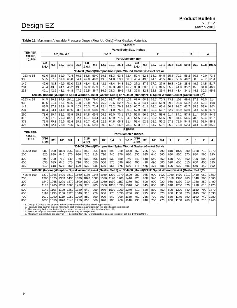
Table 12. Maximum Allowable Pressure Drops (Flow Up Only)(1) for Gasket MaterialsBAR(2)(3)
Valve Body Size, InchesTEMPER- 1/2, 3/4, & 1 1-1/2 2 3 4ATURE,�C(4)(5) Port Diameter, mmC
4.8& 6.4
9.5 12.7 19.1 25.4 4.8& 6.4
9.5 12.7 19.1 25.4 38.1 4.8& 6.4
9.5 12.7 19.1 25.4 50.8 50.8 76.2 50.8 101.6
N04400 (Monel)/Composition Spiral Wound Gasket (Gasket Set 4)
–253 to 3893
67.656.5
68.357.2
69.057.9
72.460.0
76.564.1
58.649.0
59.049.3
59.349.6
61.351.0
63.453.1
72.460.0
52.443.4
52.843.8
53.144.1
54.545.5
55.846.9
70.358.6
55.246.2
70.358.6
49.040.7
73.861.4
149204232
47.643.442.1
48.343.842.6
49.044.143.1
51.046.244.8
53.849.047.6
41.437.936.5
41.837.936.7
42.137.936.9
43.439.338.3
44.840.739.6
51.046.244.8
37.233.832.8
37.233.832.8
37.233.832.8
37.934.533.4
39.335.934.8
49.644.843.4
38.635.234.1
49.645.544.1
34.531.030.3
51.746.945.5
N06600 (Inconel)/Graphite Spiral Wound Gasket (Gasket Set 2) or N04400 (Monel)/PTFE Spiral Wound Gasket (Gasket Set 3)(5)
–253 to 3893149204
94.589.685.581.4
96.291.487.283.1
97.993.188.984.8
104.198.694.589.6
11410810398.6
77.973.870.366.9
79.074.571.468.0
80.075.272.469.0
82.778.675.271.0
87.682.779.375.2
10599.394.590.3
67.663.460.757.9
68.264.161.458.3
68.764.862.158.6
70.366.963.460.7
73.169.666.262.7
10195.891.786.9
69.666.262.760.0
97.292.488.383.4
65.562.158.655.8
11410810397.9
260316371427
78.676.573.871.0
80.477.975.272.4
82.179.376.573.8
86.984.181.478.6
95.292.488.986.2
64.862.760.758.6
65.563.461.459.3
66.264.162.160.0
69.066.964.862.1
73.171.068.366.2
87.684.881.478.6
55.854.552.450.3
56.554.952.851.0
57.255.253.151.7
58.656.555.253.1
61.459.357.255.2
84.181.478.675.8
57.956.554.552.4
81.478.675.873.1
54.552.451.049.0
94.591.788.385.5
PSI(2)(3)
TEMPER- Port Diameter, InchesATURE,�F(4)(5) 3/16
& 1/43/8 1/2 3/4 1 3/16
& 1/43/8 1/2 3/4 1 1-1/2 3/16
& 1/43/8 1/2 3/4 1 2 2 3 2 4
N04400 (Monel)/Composition Spiral Wound Gasket (Gasket Set 4)
–425 to 100200
980820
990830
1000840
1050870
1110930
850710
855715
860720
890740
920770
1050870
760630
765635
770640
790660
810680
1020850
800670
1020850
710590
1070890
300400450
690630610
700635618
710640625
740670650
780710690
600550530
605550535
610550535
630570555
650590575
740670650
540490475
540490475
540490475
550500485
570520505
720650630
560510495
720660640
500450440
750680660
N06600 (Inconel)/Graphite Spiral Wound Gasket (Gasket Set 2) or N04400 (Monel)/PTFE Spiral Wound Gasket (Gasket Set 3)(5)
–425 to 100200300400
1370130012401180
1395132512651205
1420135012901230
1510143013701300
1660157015001430
113010701020970
114510801035985
1160109010501000
1200114010901030
1270120011501090
1520144013701310
980920880840
985930890845
990940900850
1020970920880
10601010960910
1470139013301260
1010960910870
1410134012801210
950900850810
1650156014901420
500600700800
1140111010701030
1165113010901050
1190115011101070
1260122011801140
1380134012901250
940910880850
950920890860
960930900870
1000970940900
10601030990960
1270123011801140
810790760730
820795765740
830800770750
850820800770
890860830800
1220118011401100
840820790760
1180114011001060
790760740710
1370133012801240
1. Design EZ should not be used in flow down service including on-off applications.2. Pressure drop cannot exceed maximum inlet pressure as indicated in the specifications on page 2.3. The trim may be further limited by maximum pressure drops listed in tables 9 and 10.4. Pressure drops at intermediate temperatures may be interpolated.5. Maximum temperature capability of PTFE-coated N04400 (Monel) gaskets as used in gasket set 3 is 149�C (300�F).
Design EZProduct Bulletin51.1:EZMarch 2002
15
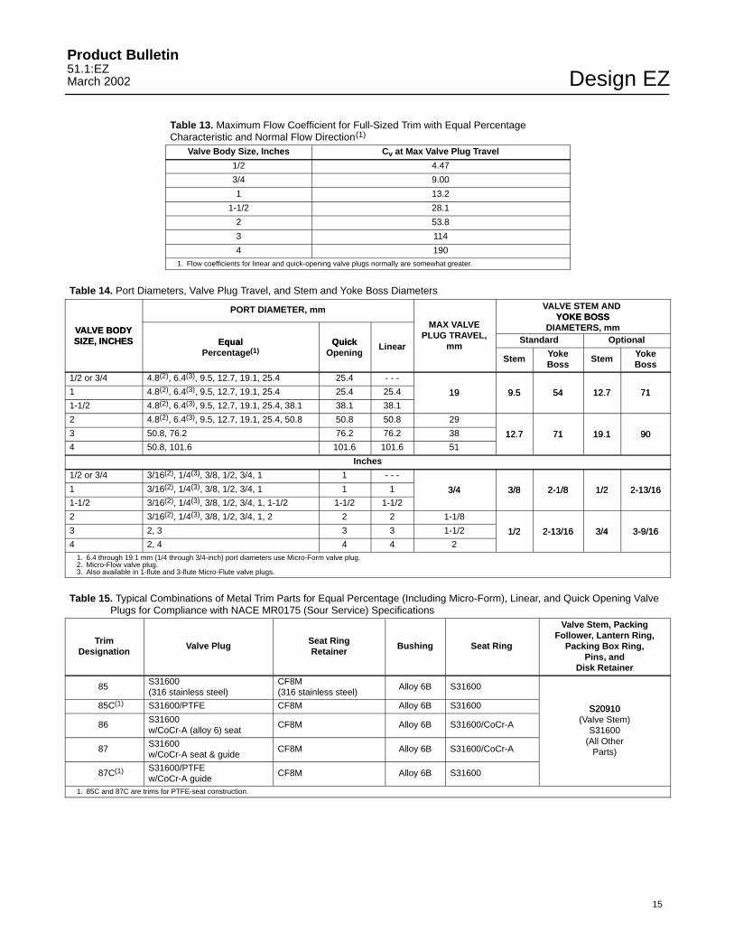
Table 13. Maximum Flow Coefficient for Full-Sized Trim with Equal PercentageCharacteristic and Normal Flow Direction(1)
Valve Body Size, Inches Cv at Max Valve Plug Travel
1/2 4.47
3/4 9.00
1 13.2
1-1/2 28.1
2 53.8
3 114
4 1901. Flow coefficients for linear and quick-opening valve plugs normally are somewhat greater.
Table 14. Port Diameters, Valve Plug Travel, and Stem and Yoke Boss Diameters
PORT DIAMETER, mm VALVE STEM AND YOKE BOSS
VALVE BODYMAX VALVE
YOKE BOSSDIAMETERS, mmVALVE BODY
SIZE, INCHES Equal QuickPLUG TRAVEL, Standard OptionalSIZE, INCHES Equal
Percentage(1)Quick
OpeningLinear mm
Stem YokeBoss
Stem YokeBoss
1/2 or 3/4 4.8(2), 6.4(3), 9.5, 12.7, 19.1, 25.4 25.4 - - -
1 4.8(2), 6.4(3), 9.5, 12.7, 19.1, 25.4 25.4 25.4 19 9.5 54 12.7 711-1/2 4.8(2), 6.4(3), 9.5, 12.7, 19.1, 25.4, 38.1 38.1 38.1
19 9.5 54 12.7 71
2 4.8(2), 6.4(3), 9.5, 12.7, 19.1, 25.4, 50.8 50.8 50.8 29
3 50.8, 76.2 76.2 76.2 38 12.7 71 19.1 904 50.8, 101.6 101.6 101.6 51
12.7 71 19.1 90
Inches
1/2 or 3/4 3/16(2), 1/4(3), 3/8, 1/2, 3/4, 1 1 - - -
1 3/16(2), 1/4(3), 3/8, 1/2, 3/4, 1 1 1 3/4 3/8 2-1/8 1/2 2-13/161-1/2 3/16(2), 1/4(3), 3/8, 1/2, 3/4, 1, 1-1/2 1-1/2 1-1/2
3/4 3/8 2-1/8 1/2 2-13/16
2 3/16(2), 1/4(3), 3/8, 1/2, 3/4, 1, 2 2 2 1-1/8
3 2, 3 3 3 1-1/2 1/2 2-13/16 3/4 3-9/164 2, 4 4 4 2
1/2 2-13/16 3/4 3-9/16
1. 6.4 through 19.1 mm (1/4 through 3/4-inch) port diameters use Micro-Form valve plug.2. Micro-Flow valve plug.3. Also available in 1-flute and 3-flute Micro-Flute valve plugs.
Table 15. Typical Combinations of Metal Trim Parts for Equal Percentage (Including Micro-Form), Linear, and Quick Opening ValvePlugs for Compliance with NACE MR0175 (Sour Service) Specifications
TrimDesignation
Valve Plug Seat RingRetainer
Bushing Seat Ring
Valve Stem, PackingFollower, Lantern Ring,
Packing Box Ring,Pins, and
Disk Retainer
85 S31600(316 stainless steel)
CF8M(316 stainless steel)
Alloy 6B S31600
85C(1) S31600/PTFE CF8M Alloy 6B S31600 S20910
86 S31600w/CoCr-A (alloy 6) seat
CF8M Alloy 6B S31600/CoCr-A
S20910(Valve Stem)
S31600
87 S31600w/CoCr-A seat & guide
CF8M Alloy 6B S31600/CoCr-A(All Other
Parts)
87C(1) S31600/PTFEw/CoCr-A guide
CF8M Alloy 6B S31600
1. 85C and 87C are trims for PTFE-seat construction.
Design EZProduct Bulletin
51.1:EZMarch 2002
16
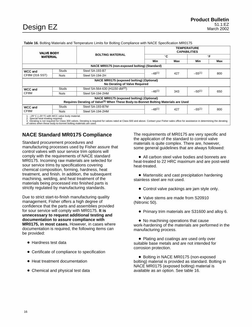
Table 16. Bolting Materials and Temperature Limits for Bolting Compliance with NACE Specification MR0175
VALVE BODY
TEMPERATURECAPABILITIESVALVE BODY
MATERIALBOLTING MATERIAL
�C �FMATERIALMin Max Min Max
NACE MR0175 (non-exposed bolting) (Standard)
WCC and Studs Steel SA-193-B7WCC andCF8M (316 SST) Nuts Steel SA-194-2H
–48(1) 427 –55(1) 800
NACE MR0175 (exposed bolting) (Optional)No Derating of Valve Required
WCC and Studs Steel SA-564-630 (H1150 dbl(2))WCC andCF8M Nuts Steel SA-194-2HM
–46(1) 343 –50(1) 650
NACE MR0175 (exposed bolting) (Optional)Requires Derating of Valve(3) When These Body-to-Bonnet Bolting Materials are Used
WCC and Studs Steel SA-193-B7MWCC andCF8M Nuts Steel SA-194-2HM
–48(1) 427 –55(1) 800
1. –29�C (–20�F) with WCC valve body material.2. Special heat treating required.3. Derating is not required for Class 300 valves. Derating is required for valves rated at Class 600 and above. Contact your Fisher sales office for assistance in determining the deratingof valves when these body-to-bonnet bolting materials are used.
NACE Standard MR0175 ComplianceStandard procurement procedures andmanufacturing processes used by Fisher assure thatcontrol valves with sour service trim options willcomply with the requirements of NACE standardMR0175. Incoming raw materials are selected forsour service trims by specifications coveringchemical composition, forming, hardness, heattreatment, and finish. In addition, the subsequentmachining, welding, and heat treatment of thematerials being processed into finished parts isstrictly regulated by manufacturing standards.
Due to strict start-to-finish manufacturing qualitymanagement, Fisher offers a high degree ofconfidence that the parts and assemblies providedfor sour service will comply with MR0175. It isunnecessary to request additional testing anddocumentation to assure compliance withMR0175, in most cases. However, in cases wheredocumentation is required, the following items canbe provided:
� Hardness test data
� Certificate of compliance to specification
� Heat treatment documentation
� Chemical and physical test data
The requirements of MR0175 are very specific andthe application of the standard to control valvematerials is quite complex. There are, however,some general guidelines that are always followed:
� All carbon steel valve bodies and bonnets areheat-treated to 22 HRC maximum and are post-weldheat-treated.
� Martensitic and cast precipitation hardeningstainless steel are not used.
� Control valve packings are jam style only.
� Valve stems are made from S20910 (Nitronic 50).
� Primary trim materials are S31600 and alloy 6.
� No machining operations that causework-hardening of the materials are performed in themanufacturing process.
� Plating and coatings are used only oversuitable base metals and are not intended forcorrosion protection.
� Bolting in NACE MR0175 (non-exposedbolting) material is provided as standard. Bolting inNACE MR0175 (exposed bolting) material isavailable as an option. See table 16.
Design EZProduct Bulletin51.1:EZMarch 2002
17
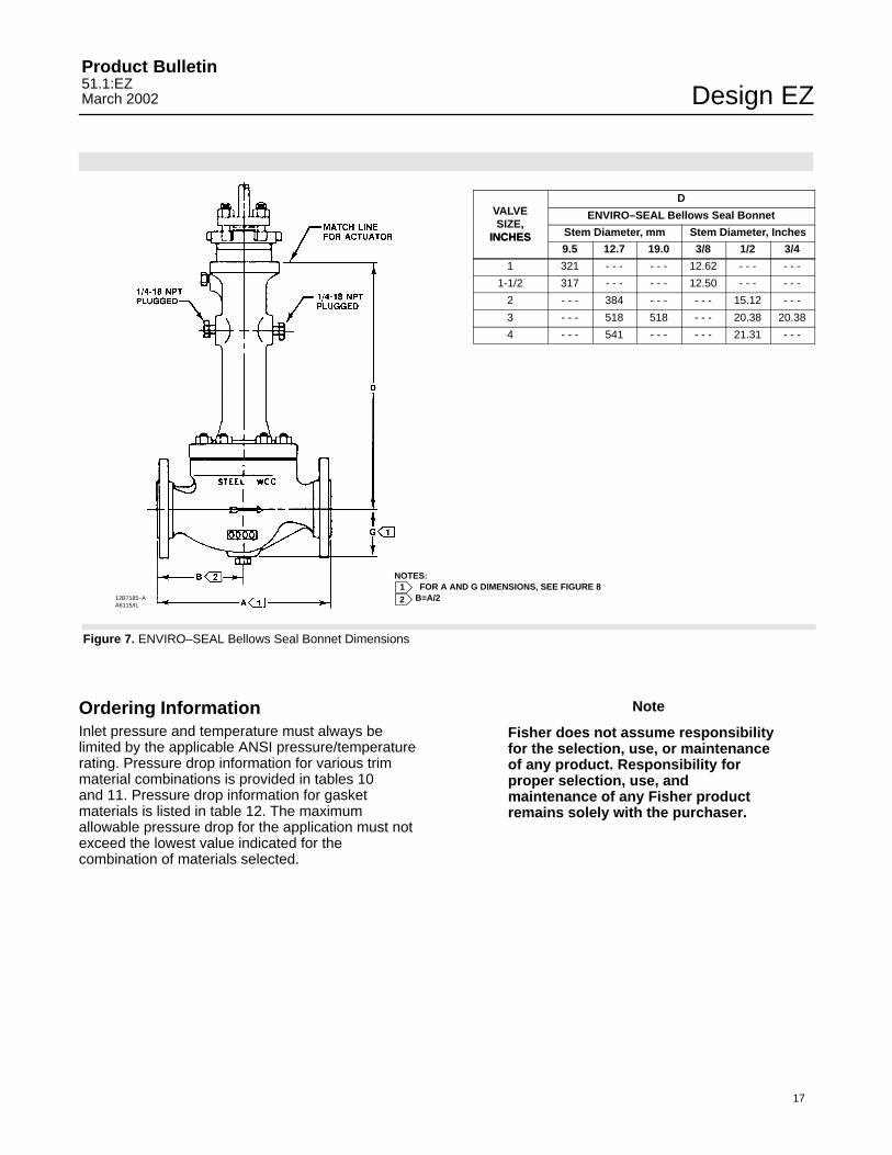
DVALVE ENVIRO–SEAL Bellows Seal BonnetSIZE,
INCHES Stem Diameter, mm Stem Diameter, InchesINCHES9.5 12.7 19.0 3/8 1/2 3/4
1 321 - - - - - - 12.62 - - - - - -
1-1/2 317 - - - - - - 12.50 - - - - - -
2 - - - 384 - - - - - - 15.12 - - -
3 - - - 518 518 - - - 20.38 20.38
4 - - - 541 - - - - - - 21.31 - - -
Ordering InformationInlet pressure and temperature must always belimited by the applicable ANSI pressure/temperaturerating. Pressure drop information for various trimmaterial combinations is provided in tables 10 and 11. Pressure drop information for gasketmaterials is listed in table 12. The maximumallowable pressure drop for the application must notexceed the lowest value indicated for thecombination of materials selected.
Note
Fisher does not assume responsibilityfor the selection, use, or maintenanceof any product. Responsibility forproper selection, use, andmaintenance of any Fisher productremains solely with the purchaser.
Figure 7. ENVIRO–SEAL Bellows Seal Bonnet Dimensions
NOTES:FOR A AND G DIMENSIONS, SEE FIGURE 8
B=A/21212B7185–A
A6115/IL
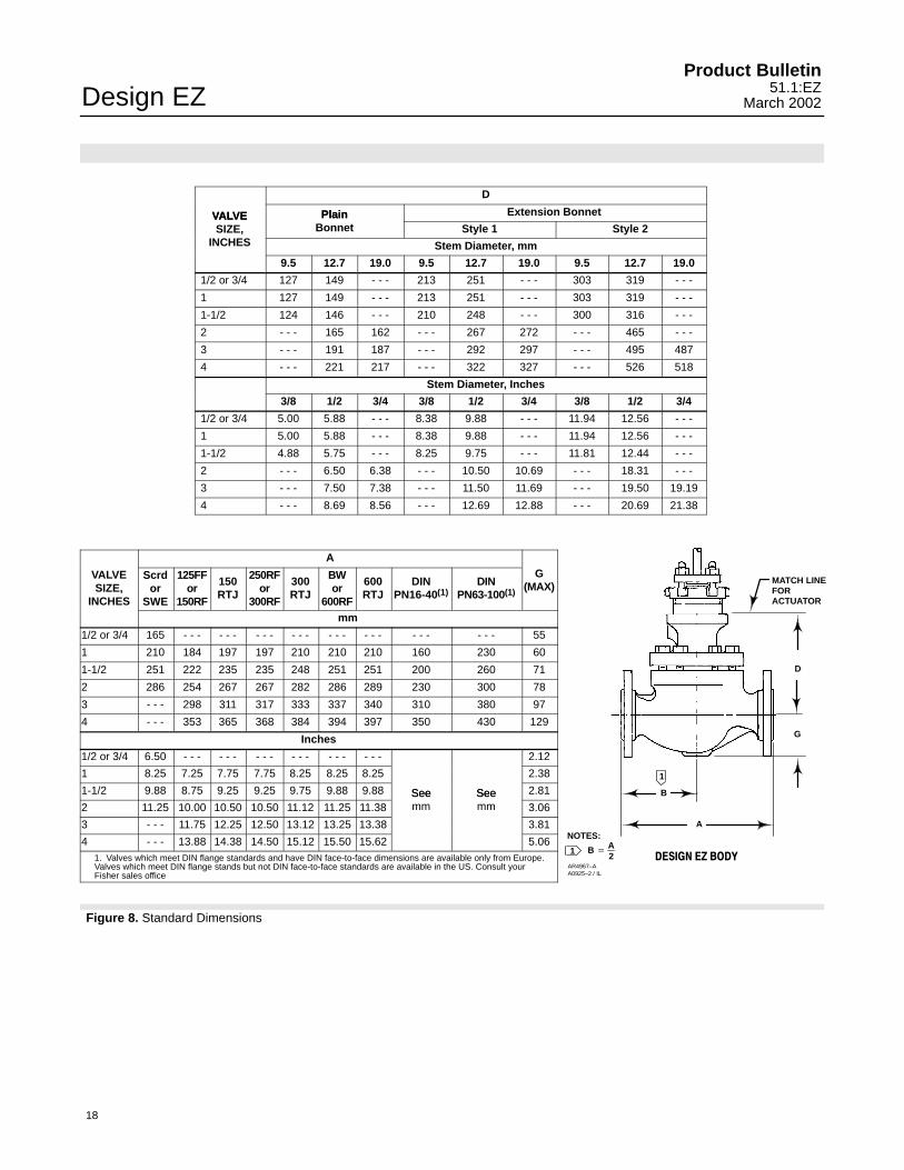
Figure 8. Standard Dimensions
A
G
D
MATCH LINEFORACTUATOR
1
1
B
AR4967–AA0925–2 / IL
NOTES:
B �
A2 �������� ��
Design EZProduct Bulletin
51.1:EZMarch 2002
18
D
VALVE Plain Extension BonnetVALVESIZE,
PlainBonnet Style 1 Style 2
INCHES Stem Diameter, mm
9.5 12.7 19.0 9.5 12.7 19.0 9.5 12.7 19.0
1/2 or 3/4 127 149 - - - 213 251 - - - 303 319 - - -
1 127 149 - - - 213 251 - - - 303 319 - - -
1-1/2 124 146 - - - 210 248 - - - 300 316 - - -
2 - - - 165 162 - - - 267 272 - - - 465 - - -
3 - - - 191 187 - - - 292 297 - - - 495 487
4 - - - 221 217 - - - 322 327 - - - 526 518
Stem Diameter, Inches
3/8 1/2 3/4 3/8 1/2 3/4 3/8 1/2 3/4
1/2 or 3/4 5.00 5.88 - - - 8.38 9.88 - - - 11.94 12.56 - - -
1 5.00 5.88 - - - 8.38 9.88 - - - 11.94 12.56 - - -
1-1/2 4.88 5.75 - - - 8.25 9.75 - - - 11.81 12.44 - - -
2 - - - 6.50 6.38 - - - 10.50 10.69 - - - 18.31 - - -
3 - - - 7.50 7.38 - - - 11.50 11.69 - - - 19.50 19.19
4 - - - 8.69 8.56 - - - 12.69 12.88 - - - 20.69 21.38
A
VALVESIZE,
INCHES
Scrdor
SWE
125FFor
150RF
150RTJ
250RFor
300RF
300RTJ
BWor
600RF
600RTJ
DINPN16-40(1)
DINPN63-100(1)
G(MAX)
mm
1/2 or 3/4 165 - - - - - - - - - - - - - - - - - - - - - - - - 55
1 210 184 197 197 210 210 210 160 230 60
1-1/2 251 222 235 235 248 251 251 200 260 71
2 286 254 267 267 282 286 289 230 300 78
3 - - - 298 311 317 333 337 340 310 380 97
4 - - - 353 365 368 384 394 397 350 430 129
Inches
1/2 or 3/4 6.50 - - - - - - - - - - - - - - - - - - 2.12
1 8.25 7.25 7.75 7.75 8.25 8.25 8.25 2.38
1-1/2 9.88 8.75 9.25 9.25 9.75 9.88 9.88 See See 2.81
2 11.25 10.00 10.50 10.50 11.12 11.25 11.38Seemm
Seemm 3.06
3 - - - 11.75 12.25 12.50 13.12 13.25 13.38 3.81
4 - - - 13.88 14.38 14.50 15.12 15.50 15.62 5.061. Valves which meet DIN flange standards and have DIN face-to-face dimensions are available only from Europe.Valves which meet DIN flange stands but not DIN face-to-face standards are available in the US. Consult yourFisher sales office

Design EZProduct Bulletin51.1:EZMarch 2002
19
SpecificationsValve Sizes
� 1/2, � 3/4, � 1, � 1-1/2, � 2, � 3, and� 4-inch
End Connection Styles(1, 2)
Cast Iron ValvesFlanged: 1 through 4-inch, Class � 125 flat-faceor � 250 raised-face flanges per ASME B16.1Screwed: 1/2 through 2-inch, consistent withASME B16.4Steel and Stainless Steel ValvesFlanged: Class � 150, 300, or 600 raised-face(RF) or ring-type joint (RTJ) flanges per ASME B16.5Screwed or Socket Welding: 1/2 through 2-inch,consistent with ASME B16.11Buttwelding (schedule 40 or 80): 1 through 4-inch,consistent with ASME B16.25
Maximum Inlet Pressure and Temperatures(1, 2)
As listed below, unless limited by maximumpressure drop or material temperature capabilitiesCast Iron ValvesFlanged: Consistent with Class 125B or 250Bpressure-temperature ratings per ASME B16.1Screwed: Consistent with Class 250 per ASMEB16.4Steel and Stainless Steel ValvesFlanged: Consistent with Class 150, 300, and600(3) per ASME B16.34Screwed or Welding: Consistent with Class 600(3)
per ASME B16.34
Maximum Pressure Drops(2)
Same as maximum inlet pressure for specificconstruction defined above, except where further
limited as shown in tables 8, 9, and 11. For softseats on NACE service, see figure 6
Shutoff Classification Per ANSI/FCI 70-2and IEC 60534-4
Metal Seating: Class IV is standard. Class V isoptional.PTFE Composition Seating: Class VI
Construction MaterialsBody and Bonnet: � Cast iron, � WCC steel,� CF8M (316 stainless steel), � WC9 chromemoly steel, or � other materials upon requestTrim Materials: See tables 3, 4, 5, and 14All Other Parts: See tables 6 and 10
Material Temperature Capabilities(2)
Body-Trim Combinations: See table 7Bolting for NACE MR0175 Specification: Seetable 16All Other Parts: See tables 6 and 10
Flow Characteristics� Equal percentage, � quick opening, and� linear. With soft seat, equal percentage isstandard
Flow DirectionUp through the seat ring
Flow Coefficients and Noise Level PredictionsSee table 13 and Catalog 12
Port Diameters and Valve Plug TravelsSee table 14
Yoke Boss and Stem DiametersSee table 14
Typical Bonnet Styles� Plain or � extension. See figure 8 for standarddimensions� ENVIRO-SEAL bellows seal bonnet. See figure3. Also, see Bulletin 59.1:070, ENVIRO-SEALBellows Seal Bonnets, for more information.
-Continued-

Design EZProduct Bulletin
51.1:EZMarch 2002
20
Specifications (Continued)Packing Arrangements
Standard Material: Single PTFE V-ringOptional Materials: See table 6ENVIRO-SEAL Packing Systems: See figure 4.ENVIRO-SEAL Packing Systems in vacuumservice: Standard ENVIRO-SEAL packingsystems can be used in vacuum service withpacking rings in standard orientation. Do notreverse the ENVIRO-SEAL PTFE packing rings.Also, see Bulletin 59.1:061, ENVIRO-SEALPacking Systems for Sliding-Stem Valves, formore information.
Approximate Weights
1/2 inch, 3/4 inch valves: 9 kg (20 lb)
1 inch valve: 11 kg (25 lb)1-1/2 inch valve: 18 kg (40 lb)2 inch valve: 36 kg (80 lb)3 inch valve: 54 kg (120 lb)4 inch valve: 75 kg (165 lb)
Valve Dimensions
See figure 8. � ENVIRO-SEAL bellows sealbonnet dimensions, figure 7
Additional Options
� Lubricator or � lubricator/isolating valve forpacking lubrication and � valve body drain plug
1. DIN (or other) ratings and end connections can usually be supplied; consult your Fisher sales office.2. Do not exceed the pressure/temperature limits in this bulletin. Any applicable standard or code limitations should not be exceeded.3. For temperatures above 427�C (800�F), the Class 600 CF8M (316 stainless steel) valve body must be derated; contact your Fisher sales office for further information. Flanged valves deratedat 38�C (100�F) do not comply with ASME B16.34.
ENVIRO-SEAL Packing System SpecificationsApplicable Stem Diameters
For Design E Valves� 9.5 mm (3/8 inches), � 12.7 (1/2), � 19.1 (3/4),� 25.4 (1), and � 31.8 (1-1/4) diameter valvestems
Maximum Pressure/Temperature Limits(1)
To Meet the EPA Fugitive Emission Standardof 500 PPM(2)
For ENVIRO-SEAL PTFE and ENVIRO-SEALDuplex packing systems: full Class 300 up to232�C (450�F)For ENVIRO-SEAL Graphite packing: 104 bar(1500 psig) at 316�C (600�F)
Construction Materials
PTFE Packing Systems
Packing Ring and Lower Wiper: PTFE V-ring(3)
Male and Female Adaptor Rings: Carbon-filledPTFE V-ringGraphite Packing Systems: Graphite ringsAnti-Extrusion Washer: Filled PTFE (notrequired for graphite packing)Lantern Ring: S31600 (316 stainless steel) (notrequired for graphite packing)Design E ValvesPacking Box Flange: S31600Spring: � 17-7PH stainless steel or � InconelPacking Follower: S31600 lined with carbon-filledPTFEPacking Box Studs: Strain-hardened 316stainless steelPacking Box Nuts: 316 stainless steel SA194Grade 8M
1. Refer to the valve specifications in this bulletin for pressure/temperature limits of valve parts. Do not exceed the pressure/temperature rating of the valve. Do not exceed any applicable codeor standard limitation.2. The Environmental Protection Agency (EPA) has set a limit of 500 parts per million (ppm) for fugitive emissions from a valve in selected VOC (Volatile Organic Compound) services.3. In vacuum service, it is not necessary to reverse the ENVIRO-SEAL PTFE packing rings.

Design EZProduct Bulletin51.1:EZMarch 2002
21

Design EZProduct Bulletin
51.1:EZMarch 2002
22

Design EZProduct Bulletin51.1:EZMarch 2002
23

Design EZProduct Bulletin
51.1:EZMarch 2002
24
Fisher Marshalltown, Iowa 50158 USACernay 68700 France Sao Paulo 05424 BrazilSingapore 128461
The contents of this publication are presented for informational purposes only, and while every effort has been made to ensure their accuracy,they are not to be construed as warranties or guarantees, express or implied, regarding the products or services described herein or their useor applicability. We reserve the right to modify or improve the designs or specifications of such products at any time without notice.
Fisher does not assume responsibility for the selection, use or maintenance of any product. Responsibility for proper selection, use and maintenance of any Fisher product remains solely with the purchaser.
�Fisher Controls International, Inc. 1979, 2002; All Rights Reserved
ENVIRO-SEAL, HIGH-SEAL, easy-e, Micro-Flow, Micro-Flute, Micro-Form, and Fisher are marks owned by Fisher Controls International,Inc., a business of Emerson Process Management. The Emerson logo is a trademark and service mark of Emerson Electric Co. All othermarks are the property of their respective owners.This product may be covered by one or more of the following patents: 5,129,625; 5,131,666; 5,056,757; 5,230,498; and 5,299,812 or underpending patents.
Emerson Process Management
www.Fisher.com