Embed Size (px)
Citation preview

Design & Experimental Validation of MIMOMultiuser Detection for Downlink Packet Data
Dragan Samardzija, Angel Lozano and Constantinos Papadias�
November 14, 2005
Abstract
In single-user MIMO communication, the first-order throughput scaling is determinedby the smallest of the number of transmit and receive antennas. This typically renders termi-nals the constraining bottleneck. In a multiuser downlink, this bottleneck can be bypassedby having the base station communicate with multiple terminals simultaneously, in whichcase the receive antennas at those terminals are effectively pooled in terms of the capac-ity scaling. This, however, requires that the base have instantaneous channel information.Without such information, the structure and statistics of the channel can be exploited toform multiple simultaneous beams towards the various users, but these beams are in gen-eral mutually interfering. This paper proposes the use of multiuser detection to discriminatethe signals conveyed over interfering beams. This approach is formulated and experimen-tally evaluated on an HSDPA MIMO testbed that involves a commercial base station, multi-antenna terminals, and custom ASICs.
�
The authors are with Bell Laboratories (Lucent Technologies), Holmdel, NJ07733, USA.
1

I Introduction
MIMO (multi-input multi-output) schemes utilizing multiple transmit and receive anten-nas are posed to be a major ingredient in the evolutionary process of wireless commu-nication. Widely recognized features associated with MIMO are: spatial diversity, signalenhancements, interference mitigation and spatial multiplexing. The latter, in particular,has driven a lot of the research over the last decade, ever since it was shown in [1, 2]that—in adequate channel conditions—the ergodic capacity (in bits/s/Hz) of a MIMOlink as function of the average SNR (signal-to-noise ratio) behaves as
���SNR ������� � ��������� ��������� SNR ��� � � � (1)
where���
and���
denote the number of transmit and receive antennas, respectively. Thislinear scaling with the number of antennas is a powerful means to achieve high spectralutilization provided that antenna arrays can be effectively deployed.
In actual wireless systems, of course, links do not operate in isolation: each base stationmust actively communicate with a plurality of users and thus a number of MIMO linkshave to coexist. The behavior expressed by (1) can be immediately translated onto a mul-tiuser environment by partitioning either time or frequency onto orthogonal sets, each ofwhich is assigned to a particular user link. Focusing on the downlink, where
�!�indicates
the number of transmit antennas at the base station while�"�
represents the number ofreceive antennas at the terminal, such orthogonal multiplexing incurs only a small loss incapacity if
���$#%���. Unfortunately, the small size and cost sensitivity of mobile termi-
nals precludes the deployment of a large number of antennas thereon and hence the mostlikely scenario for mobile systems corresponds with
���'&(���. (In some cases,
�!�may
be tightly restricted to equal�.) In these conditions, orthogonal multiplexing severely
constrains the capacity.
Without the constraint of time/frequency multiplexing, a downlink with�!�
antennas atthe base and
���antennas at each of ) users can yield a sum capacity that behaves as
���SNR ������� � ����� ) ��� ��������� SNR ��� � � � (2)
whereby the tight restrictions on�!�
become immaterial and the burden of limiting thecapacity shifts to the base station, where
���can be more easily scaled. Unfortunately,
achieving (2) requires that the base station have accurate and instantaneous informationabout the state of the fading channel between each of its antennas and those at each of themobiles [3]–[6]. This represents a total of
�!�+* ) *,���time-varying complex coefficients,
whose instantaneous tracking by the base station is not a viable option in frequency-duplexed systems1.
1In time-duplexed systems, the reciprocity in the channel propagation characteristics makes it feasible
2

Without instantaneous channel state information at the transmitter, simultaneous trans-mission to multiple users becomes challenging. In these conditions, interestingly, an-tenna correlation—often detrimental in MIMO—facilitates the formation of beams thatcan be directed to individual users providing partial isolation between their simultane-ous transmissions. Moreover, this approach (already recognized and incorporated intothe UMTS evolutionary process [7, 8]) results in simple receiver structures. The degree ofuser isolation that can be attained through the composition of beams, however, is directlydetermined by the location of the users in the cell and by the characteristics of their prop-agation channels. Unless )�� ���
, every beam will often illuminate users other than theintended one resulting in significant levels of multiuser interference.
In this paper, we formulate and experimentally evaluate a scheme that provides resilienceto strong multiuser interference when multiple beams are simultaneously active. The cor-nerstone of this scheme is the recognition that well-known MUD (multiuser techniques)[9], developed originally for CDMA (code-division multiple access), can be applied to themitigation and removal of spatial interference. This represents, to some extent, an aban-donment of the idea of simple and basically passive terminals and an embracing of theconcept of smart terminals that actively participate in the task of discriminating transmis-sions to the different users. This conceptual shift is grounded on the rapid improvementin processing power that stems from Moore’s law.
In the remainder of the paper, we describe the MIMO-MUD scheme and we quantify itsbenefits through a series of experiments executed on a testbed that involves a commercialbase station equipped with multiple antennas, terminals also equipped with multiple an-tennas, and specially designed MIMO ASICs (application specific integrated circuits). Inorder to render the experiments specific, the testbed is set up to comply with the HSDPA(high-speed downlink packet access) channel, which is foreseen to become the main ve-hicle for the provision of packet data in UMTS. To the best of our knowledge, these arethe first such reported experiments.
The paper is organized as follows. Having justified the interest in the simultaneous trans-mission to multiple users through parallel beams, in section II we review several well-known MUD approaches and discuss their applicability to the problem of mitigating theeffects of multiuser interference across beams. In Section III, in turn, we briefly describethe key features of UMTS HSDPA and describe in detail its implementation on the MIMOtestbed platform. Finally, Section IV lays down a number of experimental results thatvalidate the applicability of the chosen MIMO-MUD approach.
to track these coefficients instantaneously as long as the Doppler spread is small enough. Note, however,that reciprocity does not necessarily apply to the transceivers and thus careful calibration may be required.Note also that the wide-area communication marketplace is currently dominated by frequency-duplexedsystems.
3

II MIMO-MUD: Formulation
Although not a requirement when MUD is used, we shall limit the number of activeusers to be )�� ���
, which allows for the generation of beams that are orthogonal inorigin [10]. Larger numbers of users can of course be accommodated via time/frequency-multiplexing.
The baseband complex linear model describing the communication between the base sta-tion and the � -th terminal, ����� ��������� � )� , is�� �� ��� ��� � (3)
where � is the (��� * �
) vector received by terminal � , � � is the corresponding additivewhite Gaussian noise vector with one-sided spectral density
��� ������ � � ������
and � is the (��� * ���
) channel random matrix whose ( � ��� )-th entry represents the trans-fer coefficient2 between the
�-th base transmit antenna and the � -th receive antenna at
terminal � . In turn, � is the (��� * �
) transmit vector, common to all users and structured as
� � ! "#%$'&
"�()"(4)
where
()"is the information-bearing signal intended for terminal * while the vector &
"contains the set of deterministic coefficients that, applied to each of the transmit antennas,generate the corresponding beam. Without loss of generality, the &
"’s are chosen such
that� &" � � �
, *+�,� ��������� � )� , and the power radiated for user * is then -"� ����.
()" . ��� . It isimportant to point out that, without instantaneous channel information at the transmitter,the coefficients in the set of vectors &
", */�0� ��������� � )� , cannot depend on the random
matrices ", *1��� ��������� � )� , but only on their distributions.
From the standpoint of user � , we can conveniently rearrange (3) and (4) as
� �2 � & �( �3 465 78:9 ;�<>=@?A9 <AB:CD<FEFCDEG H�I B:C I:J 9 <>=@? �
� ! "FK# � � &"�()"
3 465 79 <AB:C ILG C I CD<FMDC�N� �3O465O7< H 9 8:C (5)
where the interference corresponds to the signals that are being beamed towards termi-nals other than � , orthogonal in origin but—in general—not upon reception because of
2In order to focus on the spatial processing aspects, the channel fading is modelled as frequency-flat.The formulation, nonetheless, can be extended to frequency-selective fading.
4
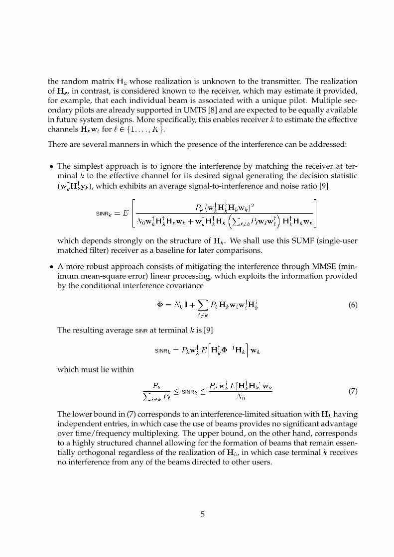
the random matrix � whose realization is unknown to the transmitter. The realizationof � , in contrast, is considered known to the receiver, which may estimate it provided,for example, that each individual beam is associated with a unique pilot. Multiple sec-ondary pilots are already supported in UMTS [8] and are expected to be equally availablein future system designs. More specifically, this enables receiver � to estimate the effectivechannels � &
"for * � � ��������� � )� .
There are several manners in which the presence of the interference can be addressed:
� The simplest approach is to ignore the interference by matching the receiver at ter-minal � to the effective channel for its desired signal generating the decision statistic� &�� �� � � , which exhibits an average signal-to-interference and noise ratio [9]
SINR� � � �� - � � &
�� �� � & � � ���� &�� �� � & � � &
�� �� ����� "FK# � - " &"&�" �� � & �
��
which depends strongly on the structure of � . We shall use this SUMF (single-usermatched filter) receiver as a baseline for later comparisons.� A more robust approach consists of mitigating the interference through MMSE (min-imum mean-square error) linear processing, which exploits the information providedby the conditional interference covariance � ����� � ! "FK
# � -" � &
"&�" �� (6)
The resulting average SINR at terminal � is [9]
SINR� � - � &
�� ��� �� �� $ �� & �which must lie within
- �� "FK# � - " � SINR� � - � &
�� ��� �� � � & ���� (7)
The lower bound in (7) corresponds to an interference-limited situation with � havingindependent entries, in which case the use of beams provides no significant advantageover time/frequency multiplexing. The upper bound, on the other hand, correspondsto a highly structured channel allowing for the formation of beams that remain essen-tially orthogonal regardless of the realization of � , in which case terminal � receivesno interference from any of the beams directed to other users.
5

� The most ambitious approach, and the one embraced in the remainder of the paper, isbased on the joint detection of the signals transmitted on all beams, of which only theintended one is decoded and passed on to the higher layers while the remaining onesare simply discarded. In this case, the average SNR per receive antenna at terminal � issimply
SNR� �
� ��� �)� � �F�� ��� � � � � ��
� " & �" ��� �� � � &
"��� ���
More specifically, the MIMO MUD solution that we propose relies on terminal � using itsknowledge of � &
"��* to perform ML (maximum likelihood) detection as
���($ ������� � �
( ����� � ��� � ��� � � " &"�()" � �
(8)
where �( � is the estimate of the signal
( � , retained and processed, while �( "
, *� � , are thesignals intended for other users, discarded after detection.
III High-Speed Downlink Packet Access MIMO Testbed
A High-Speed Downlink Packet Access
For delay-tolerant data traffic, upcoming releases of UMTS will allocate a fraction of thepower and code space to HSDPA, whose main features are:
� Time multiplexing. Users are time-multiplexed in short frames.� Multicode signaling. The entire HSDPA code space is assigned to the active user. Thus,the transmit signal consists of a superposition of orthogonal codes.� No power control. Power control is disabled.� Link adaptation. The transmit rate is adapted based on feedback from the terminals.� Hybrid ARQ. The link-layer automatic repeat request (ARQ) mechanism is combinedwith the physical-layer forward error correction [11].
6

With the incorporation of MIMO, the possibility of having active users on separate beamsis enabled and, correspondingly, the use of MIMO-MUD becomes alluring. In the re-maining, we validate this idea using a � -MHz MIMO testbed that operates at � � � GHzand supports
��� ��� antennas at the base and�!� ��� antennas at each terminal [12]. The
testbed is currently compliant with the above-described HSDPA features.
In order to test the MIMO-MUD concept under the harshest conditions, trivial beams areemployed: each &
"is identically zero except for the * -th entry, which is set to
�. With that,
the beams give rise to severe interference as no attempt is made to isolate the transmissionto different users.
B Transmitter Implementation
At the base, omnidirectional vertically polarized��� � -wavelength antennas are set � wave-
lengths apart along a line at a height of about � m. As shown in Fig. 1, the transmitter ismounted on a prototype Lucent base station ( � �� ���
���prototype). A prototype mezza-
nine board is used to implement the physical and MAC (medium access control) layers.The rest of the base station, including RF (radio frequency) front-end, backplane and net-work interface, is also used. The RF front-end, in particular, meets the EVM (error vectormagnitude) requirements set by Release 5 of the UMTS specifications.
A FPGA (field programmable gate array) is used to implement the multi-antenna physicallayer transmitter. The corresponding functional block scheme is depicted in Fig. 2 witheach functional block being HSDPA compliant. Up to � independent data streams �
",* � � ��� � � � � � , are passed down from the MAC layer, each intended for a distinct user.
After being independently processed, every stream is radiated out of one of the antennaswith a ��� -bit CRC (cyclic redundancy code) word appended to each data block. Thesedata blocks are encoded using a rate-
��� � turbo code and the desired transmission data rateis realized via a rate matching procedure that performs either puncturing or repetition ofthe encoder outputs. Binary words are then mapped to a particular QAM constellation(both QPSK and 16-QAM are supported by HSDPA) and then assigned to specific length-���
orthogonal channelization (i.e., spreading) codes. In addition, a unique pilot drawnfrom a set of secondary UMTS pilots [8] is assigned to each transmit antenna. The pilotsare mutually orthogonal and orthogonal to the data-carrying spreading codes. The pilotpower is set to
�����of the total radiated power [13]. The same scrambling code is used
at every transmit antenna and the primary and secondary synchronization channels arealso transmitted allowing mobile terminals to achieve chip-level, slot-level and frame-level synchronization and to perform cell search procedures. The above functional blocks(in Fig. 2) are implemented on FPGA Xilinx Virtex II 6000, with the clock rate of 61.44MHz using approximately
� � � of the available logic (i.e., logic slices), for each user (i.e.,
7

transmitted stream). Furthermore, approximately 100 KByte of memory is used per user.
The rate controller in Fig. 2 is closely coupled with the multiuser scheduling that is exe-cuted at the MAC layer. Specifically, the rate controller is responsible for setting, for each� -msec time transmission interval, the rate matching parameters, modulation (QPSK or16-QAM) and number of active spreading codes . Effectively, it optimizes the transmis-sion data rates for a given channel and data traffic conditions. For the experimental re-sults presented in Section IV, QPSK modulation was used with rate-
��� � coding and���
length-���
active spreading codes.
To support multiple users, the MAC layer is implemented on a processor platform. Specif-ically, the multiuser scheduling and Hybrid-ARQ are implemented on a digital signalprocessor (Texas Instruments DSP 6701), while interfacing to an IP (internet protocol)network is implemented on an embedded processor (Motorola PowerPC 8260). The stan-dard HSDPA specifications are retained at the MAC layer and thus only the physical layeris aware of the presence of MIMO.
C Receiver Implementation
As shown in Fig. 3, the terminal antennas are low-profile bow-tie printed dipoles withalternating � � � polarizations occupying vertexes of an
� � ��� � * � � ��� � rectangle with the en-tire array fitting on the back of a laptop. Note that the fifth antenna, which is placed inthe center of the rectangle (in Fig. 3), is vertically polarized and is used for the uplinktransmission (a conventional single transmit antenna uplink is used). Physically differentdownlink and uplink antennas are used to simplify the design by avoiding implementa-tion of an analog antenna coupler (which is otherwise needed when the same antenna isused both for the uplink and downlink, simultaneously).
The functional block scheme of the multi-antenna physical layer receiver is illustratedin Fig. 4, where �� � is the estimate of the transmitted data for terminal � . After the AD(analog-to-digital) conversion, the received signal is sent to the MIMO-MUD ASIC which,in turn, outputs LLRs (log-likelihood ratios) that are then fed to the rate dematcher. Afterdematching, the turbo-decoder ASIC performs iterative decoding. The physical layer isimplemented on � interconnected printed circuit cards that are next described in moredetail.
Card 1 implements the analog RF front-end outputting up to � complex baseband signals,each corresponding to a receive antenna. A heterodyne receiver with a
� � � -MHz IF andnoise figure under
�dB is utilized, after which
���-bit AD conversion takes place.
Card 2 contains the basic processing elements of the multi-antenna receiver: (i) MIMO-
8

MUD ASIC 3 [14] and (ii) turbo decoder ASIC [15]. A block scheme of the MIMO detectoris given in Fig. 5. The detector is based on a bank of despreaders matched to the data-carrying spreading codes, whose outputs are fed into the ML detection that correspondswith (8). In Fig. 5, �
(� � , � � � ���������!��� , is the estimate of the transmitted symbol corre-
sponding to code�
for user � . Furthermore, each LLR corresponds to�
channel bit withan
�-bit resolution.
An estimate of the MIMO channel, essential to the detection process, is obtained from anon-chip estimator. This is illustrated in Fig. 6, where � � denotes the estimate of the ( � ��� )-thentry of the MIMO channel matrix � . The on-chip estimator is based on a bank of de-spreaders corresponding to each of the length- � � � pilot codes. In the case of frequency-flatfading, the presented estimator results in an ML channel estimate (see [13] and referencestherein). To lower the estimation noise, an optional integrator with forgetting factor isavailable. For the experimental results in Section IV, � � .
Card 3, finally, holds the FPGA that acts as interconnect matrix between ADs, MIMO-MUD ASIC and turbo decoder ASIC. Furthermore, it executes (i) synchronization, (ii)frequency offset compensation, (iii) physical channel desegmentation (iv) rate dematch-ing, (v) CRC check, and numerous auxiliary functions. To all of these functions, the useof MIMO is immaterial. The above functions are implemented on FPGA Xilinx Virtex II6000, with the clock rate of 61.44 MHz using approximately � � � of the available logic and70 KByte of memory.
IV MIMO-MUD Experimental Results
Indoor over-the-air measurements, mostly in static conditions, were carried out in a lab-oratory/office environment. The receiver was placed at various locations in the room.QPSK modulation was used with rate-
��� � coding and���
length-���
orthogonal codes. Themeasurements include thermal as well as quantization noise.
We measured FERs (frame error rates) with the � -msec time transmission interval spec-ified for HSDPA. Based on the FER and on the � � � � -MHz chip rate, the throughput � isobtained as
��� � � � � ��� $ �$ � � � ������� � � ������� �This corresponds to a system with ARQ where the frames in error are discarded.
Fig. 7 presents the measured CDF (cumulative distribution) of � for a transmit power of�dBm (
�mW) over � � locations. We show, for
��� ��� and ) ��� terminals, each with�!� � �
,3The MIMO-MUD ASIC is manufactured using 0.18-micron CMOS technology, with 438000 gates, 300
mW core power, and size of 3.7 mm � 3.7 mm.
9

a comparison of SUMF and MIMO-MUD receivers. Also depicted is the throughput for) � �
and��� � �
, for which the SUMF is optimal. Notice the large gains arising from theuse of multiple antenna transmission. It is also worth noticing the value of multi-user de-tection alone, which for example leads to a throughput increase of more than 0.5 Mbps (atthe 50% percentile point) compared to the corresponding single-user optimal transceiver.Fig. 8 presents the average throughput for different transmit power levels. MIMO-MUDresults, at high transmit powers, in an almost � -fold increase in average throughput. Itshould be noted that a higher order constellation could be used to combat the flooringeffect shown in the figure for the single user transceivers. However, multi-user detectionwould still offer some gains, as evidenced by the fact that it has superior performanceeven before flooring starts to occur (e.g. at 0 dBm transmit power). Fig. 9 presents theaverage throughput for
�!� � ��� � � � � � with��� ��� and with
�dBm (solid line) and
���dBm
(dashed line) transmit powers. Fig. 10 presents corresponding results for�"� � � . In both
Fig. 9 and Fig. 10 we see a sizeable improvement in throughput associated with the useof MIMO-MUD, especially when
���is larger than or comparable to
�!�. Although, for
higher���
, the SUMF approaches the MIMO-MUD throughput, this is in part an artifactof the fact that only QPSK is used. With
���-QAM available, we expect the MIMO-MUD
advantage to be largely sustained.
In order to further demonstrate the capabilities of our HSDPA MIMO prototype, we alsoimplemented a video-streaming application (using the Real-Time Streaming Protocol).Video streaming rates of up to 2 Mbps were achieved over the air (the higher layer ARQintroduced only a slight reduction in the overall throughput). In terms of interferencemitigation performance, when using real-time video as each user’s signal, MUD at thereceiver performed very closely to the predicted behaviour and managed to separate theinterfering video signals without any perceived degradation of performance as comparedto each user’s video stream transmitted alone. More information about these experimentscan be found in [16].
V Conclusions
Multiuser detection is a natural approach to signal detection in multiuser environments.Although much of the developments in this area have been motivated by CDMA, mul-tiuser techniques are equally well suited to the spatial processing that arises with theuse of MIMO, where the role of the CDMA spreading sequences is played by the fadingcoefficients between the various transmit and receive antennas.
In this paper, we have applied MUD to the detection of mutually interfering downlinkbeam transmissions aimed at different terminals. Without instantaneous channel stateinformation at the base, these beams cannot be rendered orthogonal at the terminal re-
10

ceivers. Rather than simply enduring their mutual interference, we have proposed tojointly detect the signals transmitted on the intended and unintended beams.
Besides formulating such MIMO-MUD reception, we have experimentally validated theapproach using a testbed that includes a commercial multi-antenna base station, multi-antenna terminals and custom MIMO ASICs. The results confirm the power of MUD,especially when the number of receive antennas at each terminal does not exceed thenumber of transmit antennas at the base.
Besides the application that has constituted the focus of the paper, MIMO-MUD schemescarry over to other multiuser MIMO settings. If, instead of parallel beams, time/frequencymultiplexing is utilized, MIMO-MUD can be applied to mitigate the impact of interfer-ence from neighboring co-channel base stations. Although, in this case, individualizingthe channel estimate for each interfering base station may not always be feasible, joint de-tection of desired and undesired transmissions can be applied to a few dominant neigh-bors. Furthermore, simpler linear MMSE processing can be applied if only the aggregateinterference covariance in (6) can be estimated. Theoretical assessments of the advantageassociated with knowledge of such covariance in MIMO communication can be foundin [17]–[19]. Actually, even before the advent of MIMO systems, earlier pioneering con-tributions had already demonstrated the interference suppression capability of multiplereceive antennas [10, 20, 21].
Acknowledgments
The authors gratefully acknowledge the support and encouragement of many colleaguesled by Theodore Sizer, Reinaldo Valenzuela and Stephen Wilkus, all from Lucent Tech-nologies. The authors are particularly grateful to Peter Bosch, Sape Mullender, SusanWalker, Tran Cuong, Francis Mullany, Eric Beck, Arnold Siegel, Thomas Gvoth and IlyaKorisch for their support. Part of this work was done under the IST project FITNESS,sponsored and funded by the FP5 European research framework.
11

References
[1] G. J. Foschini and M. J. Gans, “On the limits of wireless communications in a fading en-vironment when using multiple antennas,” Wireless Personal Communications, pp. 315–335,1998.
[2] I. E. Telatar, “Capacity of multi-antenna Gaussian channels,” Eur. Trans. Telecom, vol. 10, pp.585–595, Nov. 1999.
[3] W. Yo and J. M. Cioffi, “Sum capacity of a gaussian vector broadcast channel,” IEEE Intern.Symp. on Inform. Theory, p. 498, July 2002.
[4] G. Caire and S. Shamai, “On achievable throughput of a multiantenna Gaussian broadcastchannel,” IEEE Trans. on Inform. Theory, vol. 49, no. 7, pp. 1691–1706, July 2003.
[5] P. Viswanath and D. N. C. Tse, “Sum capacity of vector gaussian broadcast channel anduplink-downlink duality,” IEEE Trans. on Inform. Theory, vol. 49, no. 8, pp. 1912–1921, Aug.2003.
[6] S. Vishwanath, N. Jindal, and A. Goldsmith, “On the capacity of multiple input multipleoutput broadcast channel,” IEEE Intern. Conf. on Communications, vol. 3, pp. 1444–1450, May2002.
[7] K.I. Pedersen, P.E. Mogensen, and J. Ramiro-Moreno, “Application and performance ofdownlink beamforming techniques in UMTS,” IEEE Comm. Magazine, pp. 134–143, Oct. 2003.
[8] “Beamforming enhancements,” TR 25.887 v. 1.3.0, 3rd Generation Partnership Project, Oct. 2002.
[9] S. Verdu, Multiuser Detection, Cambridge University Press, 1998.
[10] J. H. Winters, “On the capacity of radio communication systems with diversity in a Rayleighfading environment,” IEEE J. Select. Areas Commun., vol. 5, no. 5, pp. 871–878, June 1987.
[11] Q. Zhang and S. A. Kassam, “Hybrid ARQ with selective combining for fading channels,”IEEE J. Select. Areas Commun., vol. 17, pp. 867–880, May 1999.
[12] A. Burg, E. Beck, D. Samardzija, M. Rupp, and et al., “Prototype experience for MIMO BLASTover third generation wireless system,” IEEE JSAC Special Issue on MIMO Systems and Appli-cations, vol. 21, no. 3, April 2003.
[13] D. Samardzija and N. Mandayam, “Pilot assisted estimation of MIMO fading channel re-sponse and achievable data rates,” IEEE Transactions on Signal Processing, Special Issue onMIMO, vol. 51, no. 11, pp. 2882–2890, November 2003.
[14] D. C. Garrett, L. M. Davis, and G. K. Woodward, “19.2 Mbit/s 4 x 4 BLAST/MIMO detectorwith soft ML outputs,” IEE Electr. Letters, vol. 39, no. 2, pp. 233–235, Jan. 2003.
[15] M. Bickerstaff, L. Davis, C. Thomas, D. Garrett, and C. Nicol, “A 24 Mb/s radix-4 turbodecoder,” IEEE Intern. Solid-State Circuits Conf., Feb. 2003.
12

[16] IST-FITNESS D3.3, “Description of UMTS MTMR reconfigurability demo,” www.ist-fitness.org.
[17] A. Lozano and A. M. Tulino, “Capacity of multiple-transmit multiple-receive antenna archi-tectures,” IEEE Trans. on Inform. Theory, vol. 48, Dec. 2002.
[18] A. Lozano, A. M. Tulino, and S. Verdu, “Multiple-antenna capacity in the low-power regime,”IEEE Trans. on Inform. Theory, vol. 49, no. 10, Oct. 2003.
[19] A. L. Moustakas, S. H. Simon, and A. M. Sengupta, “MIMO capacity through correlatedchannels in the presence of correlated interferers and noise: a (not so) large N analysis,”IEEE Trans. on Inform. Theory, vol. 49, no. 10, pp. 2545–2561, Oct. 2003.
[20] J. H. Winters, J. Salz, and R. D. Gitlin, “The impact of antenna diversity on the capacity ofwireless communication systems,” IEEE Trans. Commun., vol. 42, no. 2/3/4, pp. 1740–1751,Feb./March/Apr. 1994.
[21] J. H. Winters, “Optimum combining in digital mobile radio with cochannel interference,”IEEE J. Select. Areas Commun., vol. 2, no. 4, pp. 528–539, July 1984.
13
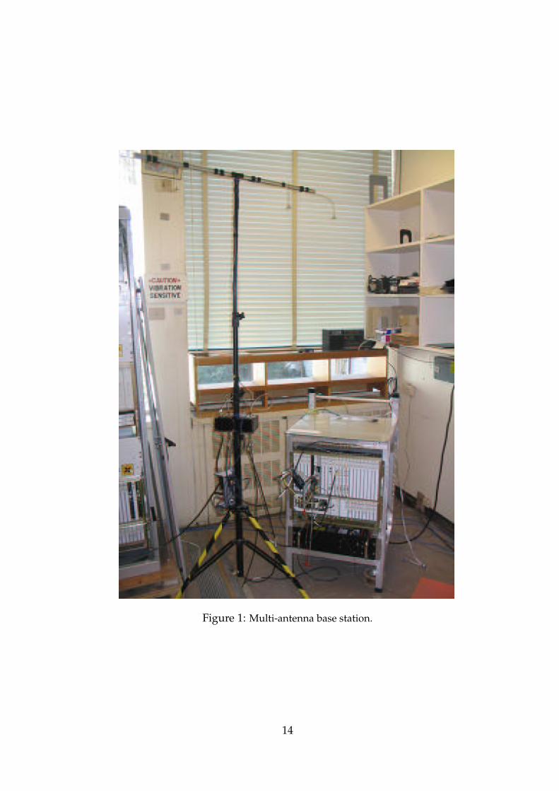
Figure 1: Multi-antenna base station.
14

Figure 2: Functional block scheme of multi-antenna HSDPA physical layer transmitter.
Figure 3: Terminal and receive antenna array.
15

Figure 4: Functional block diagram of multi-antenna HSDPA physical layer receiver.
Figure 5: MIMO detection as implemented on the MIMO-MUD ASIC.
16

Figure 6: MIMO channel estimation as implemented on the MIMO-MUD ASIC.
17

0 0.5 1 1.5 2 2.5 3 3.5 4 4.5 50
0.1
0.2
0.3
0.4
0.5
0.6
0.7
0.8
0.9
1
CD
F
Throughput [Mbps]
MIMO−MUD, nT = 4, n
R = 1
SUMF, nT = 4, n
R = 1
SUMF, nT = 1, n
R = 1
Figure 7: Measured CDF of throughput for � dBm over ��� locations.
18

−10 −8 −6 −4 −2 0 2 4 6 8 100
1
2
3
4
5
6
7
8
Ptx [dBm]
Thr
ough
put [
Mbp
s]
MIMO−MUD, nT = 4, n
R = 1
SUMF, nT = 4, n
R = 1
SUMF, nT = 1, n
R = 1
Figure 8: Measured average throughput vs. transmit power over ��� locations.
19

1 2 3 40
1
2
3
4
5
6
7
8
9
10
Number of receive antennas nR
Thr
ough
put [
Mbp
s]
MIMO−MUD, nT = 4
SUMF, nT = 4
dashed: 10 dBmsolid: 0 dBm
Figure 9: Measured average throughput vs. ��
at � dBm (solid line) and� � dBm (dashed line)
over ��� locations.
20

1 2 3 41
1.5
2
2.5
3
3.5
4
4.5
5
Number of receive antennas nR
Thr
ough
put [
Mbp
s]
MIMO−MUD, nT = 2
SUMF, nT = 2
dashed: 10 dBmsolid: 0 dBm
Figure 10: Measured average throughput vs. ��
at � dBm (solid line) and� � dBm (dashed line)
over ��� locations.
21