Embed Size (px)
Citation preview

International Research Journal of Engineering and Technology (IRJET) e-ISSN: 2395-0056
Volume: 08 Issue: 03 | Mar 2021 www.irjet.net p-ISSN: 2395-0072
© 2021, IRJET | Impact Factor value: 7.529 | ISO 9001:2008 Certified Journal | Page 2222
DESIGN EVALUTION AND OPTIMIZATION OF NOZZLE USED IN DIESEL
ENGINE
AREBOINA SANDEEP1, Mr. J. CHANDRA SEKHAR2, Dr. K. VIJAY KUMAR 3, Dr. M. SREEDHAR REDDY4
1M. TECH Student, Dept. of Mechanical Engineering, MRCE College, Telangana, India 2Assistant Professor, Dept. of Mechanical, Malla Reddy College of Engineering, Telangana, India
3Professor, Dept. of Mechanical, Malla Reddy College of Engineering, Telangana, India 4Principal, Malla Reddy College of Engineering, Telangana, India
---------------------------------------------------------------------***----------------------------------------------------------------------
Abstract - The nozzle is used to convert the chemical thermal energy generated in the combustion chamber into kinetic energy. The nozzle converts the low velocity, high pressure, high temperature gas in the combustion chamber into high velocity gas of lower pressure and temperature. Nozzle is a device designed to control the rate of flow, speed, direction, mass, shape, and/or the pressure of the stream that exhaust from them. Nozzles come in a variety of shapes and sizes depending on the
mission of the rocket, this is very important for the
understanding of the performance characteristics of rocket.
Convergent divergent nozzle is the most commonly used nozzle
since in using it the propellant can be heated in combustion
chamber.
In this thesis the convergent divergent nozzle changing the
different nozzle diameters and different fluids at different
velocities. We modeled convergent divergent nozzle changing
with different nozzle diameters and Analyzed the convergent
divergent nozzle with different mass flow rates to determine
the pressure drop, heat transfer coefficient, and velocity and
heat transfer rate for the fluid by CFD technique.
Key Words: Nozzle, Diesel engine, fuel injector, CREO
software, ANSYS 1. INTRODUCTION
The primary challenges towards developing new
diesel engines for passenger cars lie in the strict future
emission legislation in combination with the customer’s
demands for steadily improving performance. For example,
the emission limitations of Tier 2 Bin 5 require an advanced
after treatment system and a robust combustion process that
minimizes emissions in the process of them being formed.
Advancements in the technology of Diesel Injection (DI)
systems have played in important role in the improvements
that have been made up to this point. Combining the
reduction in nozzle orifice diameters through enhanced flow
characteristics with increased injection pressures provides
an opportunity to develop engines featuring high power
density and reduced emissions. The primary drawback to
these modern spray hole geometries is that they often suffer
a reduction of power output during long term operation.
Other studies have identified these critical formations of
deposits as the main reason for this behavior.
Fig-1.1: A sectional view of fuel injector
Basic mechanisms can be used to explain the
formation and removal of deposits in internal combustion
engines These mechanisms act independently of the location
of formed deposits (e.g. injection nozzles, heat changer) and
of the combustion process (e.g. IDI, DI; diesel or gasoline).
The model described in the study illustrates the
interaction of a wall with the enclosing flow regime. The
transport of particles to the wall is based on the process of
thermophores is this process results in the force of gas
particles in the direction of the temperature depression. It is
amplified with an increasing temperature differential
between wall (cold)and fluid (hot). This process results are
an increasing concentration of deposit-building particles
near the wall.

International Research Journal of Engineering and Technology (IRJET) e-ISSN: 2395-0056
Volume: 08 Issue: 03 | Mar 2021 www.irjet.net p-ISSN: 2395-0072
© 2021, IRJET | Impact Factor value: 7.529 | ISO 9001:2008 Certified Journal | Page 2223
Fig-1.2: Components in fuel injector
High 2 turbulence near the wall may reduce the
force of the aerosol again to a mean value, compensating for
an increased temperature difference. The deposits are
composed of attached particles (solid and liquid) and gas
(Figure 1).
Condensation and adsorption of gaseous
compounds at the cold wall promotes the formation process.
At this point, the growth of the deposits is now mainly
influenced by the sticking, impaction and incorporation of
particles the adsorption of gaseous components and the
chemical reactions (as pyrolysis, dehydration and
polymerization, etc.), lead to the compaction of the deposits].
The removal of deposits has analogous physical mechanisms.
The chemical mechanism is oxidation destroying the
organic compounds in the coating Evaporation and
desorption reduce the gaseous fraction dissolved in the
deposits. Abrasion is caused by strong aerodynamic forces
and breaking-off, due to high temperature changes, resulting
in inhomogeneous extensions of the wall and deposit layer.
The corresponding shearing stresses initiate the
breaking-off process the soluble fraction of the deposits is
washed off by solvents (e.g. water as solvent for salt
compounds)
2. INTRODUCTION TO ANSYS
1) Structural Analysis
ANSYS Autodyn is computer simulation tool for simulating the response of materials to short duration severe loadings from impact, high pressure or explosions.
2) Fluid Dynamics
ANSYS Fluent, CFD, CFX, FENSAP-ICE and related software are Computational Fluid Dynamics software tools used by engineers for design and analysis. These tools can simulate fluid flows in a virtual environment — for example, the fluid dynamics of ship hulls; gas turbine engines (including the compressors, combustion chamber, turbines and afterburners); aircraft aerodynamics; pumps, fans, HVAC systems, mixing vessels, hydro cyclones, vacuum cleaners, etc.
2.1 CFD ANALYSIS OF DIESEL ENGINE NOZZLE
FLUID- DIESEL
Velocity inlet = 200m/s, 300m/s & 400m/s
Fig-2.1: Imported model
Fig-2.2: MESHED MODEL

International Research Journal of Engineering and Technology (IRJET) e-ISSN: 2395-0056
Volume: 08 Issue: 03 | Mar 2021 www.irjet.net p-ISSN: 2395-0072
© 2021, IRJET | Impact Factor value: 7.529 | ISO 9001:2008 Certified Journal | Page 2224
Fig-2.3: SPECIFYING THE BOUNDARIES FOR INLET &
OUTLET
Update
2.2 FLUID- DIESEL
DIESEL ENGINE NOZZLE DIA. 50MM
VELOCITY INLET = 200m/s
PRESSURE
Fig-2.4: PRESSURE
Fig-2.5: VELOCITY
Fig-2.6: HEAT TRANSFER COEFFICIENT
2.3 VELOCITY INLET = 300m/s
Fig-2.7: PRESSURE
Fig-2.8: VELOCITY
International Research Journal of Engineering and Technology (IRJET) e-ISSN: 2395-0056
Volume: 08 Issue: 03 | Mar 2021 www.irjet.net p-ISSN: 2395-0072
© 2021, IRJET | Impact Factor value: 7.529 | ISO 9001:2008 Certified Journal | Page 2225
Fig-2.9: HEAT TRANSFER COEFFICIENT
Fig-2.10: MASS FLOW RATE & HEAT TRANSFER RATE
2.4 VELOCITY INLET = 400m/s
Fig-2.11: PRESSURE
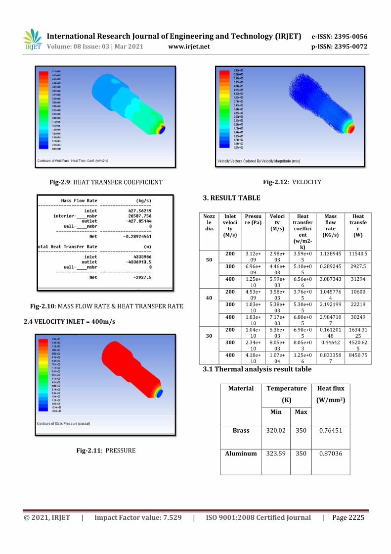
Fig-2.12: VELOCITY
3. RESULT TABLE
Nozzle
dia.
Inlet veloci
ty (M/s)
Pressure (Pa)
Velocity
(M/s)
Heat transfer coeffici
ent (w/m2-
k)
Mass flow rate
(KG/s)
Heat transfe
r (W)
50
200 3.12e+09
2.98e+03
3.59e+05
1.138945 11540.5
300 6.96e+09
4.46e+03
5.10e+05
0.289245 2927.5
400 1.25e+10
5.99e+03
6.56e+06
3.087343 31294
40
200 4.53e+09
3.58e+03
3.76e+05
1.0457764
10600
300 1.03e+10
5.38e+03
5.30e+05
2.192199 22219
400 1.83e+10
7.17e+03
6.80e+05
2.9847107
30249
30
200 1.04e+10
5.36e+03
6.90e+05
0.16120148
1634.3125
300 2.34e+10
8.05e+03
8.05e+03
0.44642 4520.625
400 4.18e+10
1.07e+04
1.25e+06
0.8333587
8450.75
3.1 Thermal analysis result table
Material Temperature
(K)
Heat flux
(W/mm2)
Min Max
Brass 320.02 350 0.76451
Aluminum 323.59 350 0.87036

International Research Journal of Engineering and Technology (IRJET) e-ISSN: 2395-0056
Volume: 08 Issue: 03 | Mar 2021 www.irjet.net p-ISSN: 2395-0072
© 2021, IRJET | Impact Factor value: 7.529 | ISO 9001:2008 Certified Journal | Page 2226
4. CONCLUSIONS Nozzles come in a variety of shapes and sizes
depending on the mission of the rocket, this is very
important for the understanding of the performance
characteristics of rocket. Convergent divergent nozzle is the
most commonly used nozzle since in using it the propellant
can be heated in combustion chamber.
In this thesis the convergent divergent nozzle
changing the different nozzle diameters and different fluids
at different velocities. We modeled convergent divergent
nozzle changing with different nozzle diameters.
By observing the CFD analysis of diesel engine
nozzle the pressure, velocity, heat transfer rate and mass
flow rate values are increases by increasing the inlet
velocities and decreasing the nozzle dia.
By observing the thermal analysis, heat flux is more
for aluminum alloy compared with brass material.
So, it can be concluded the diesel engine nozzle
efficiency were more when the nozzle dia. decreases.
ACKNOWLEDGEMENT The authors express their deep sense of gratitude to Dr. K. VIJAY KUMAR, HOD, Department of Mechanical Engineering, Malla Reddy College of Engineering, Mysammaguda, Hyderabad. For the support extended during the execution of the research. The authors also thank Mr. J. Chandra Sekhar, Assistant Professor (Department of Mechanical Engineering), MRCE, for the help and guidance provided during this work.
REFERENCES
[1] J.B. Heywood, “Internal Combustion Engine
Fundamentals”, McGraw-Hill Book Co, pp 493-494,
1988.
[2] M. Volmajer, B. Kegl, “Experimental and numerical
analysis of fuel flow in the diesel engine injection
nozzle”, Journal of Kones. Combustion Engines, Vol. 8,
No. 1-2, 2001.
[3] D. Ing. H. Tschöke, “Diesel distributor fuel-injection pumps”, Robert Bosch GmbH, pp 12-53, 1999.
[4] B. Challen R. Baranescu, “Diesel Engine Reference Book”
Reed Educational and Professional Publishing Ltd.,
Second Edition, pp.260-301, 1999.
[5] Z. Li, M. Kokkolaras, D. Jung, Panos Y. Papalambros and
D. N. Assanis, “An Optimization Study of Manufacturing
Variation Effects on Diesel Injector Design with
Emphasis on Emissions”, SAE International, 2004.
BIOGRAPHIES
Name: Areboina Sandeep MTech (CAD/CAM) Scholar, Department of Mechanical Engineering, MRCE, MYSAMMAGUDA, HYDERABAD, TELANGANA, INDIA