Embed Size (px)
Citation preview
Purdue UniversityPurdue e-Pubs
Open Access Dissertations Theses and Dissertations
Fall 2013
Design, Development, and Testing of a ConformalPower Control Interface for Thrust VectoringAircraftDavid RozovskiPurdue University
Follow this and additional works at: https://docs.lib.purdue.edu/open_access_dissertations
Part of the Aerospace Engineering Commons, Industrial Engineering Commons, and thePsychology Commons
This document has been made available through Purdue e-Pubs, a service of the Purdue University Libraries. Please contact [email protected] foradditional information.
Recommended CitationRozovski, David, "Design, Development, and Testing of a Conformal Power Control Interface for Thrust Vectoring Aircraft" (2013).Open Access Dissertations. 74.https://docs.lib.purdue.edu/open_access_dissertations/74

Graduate School ETD Form 9 (Revised 12/07)
PURDUE UNIVERSITY GRADUATE SCHOOL
Thesis/Dissertation Acceptance
This is to certify that the thesis/dissertation prepared
By
Entitled
For the degree of
Is approved by the final examining committee:
Chair
To the best of my knowledge and as understood by the student in the Research Integrity and Copyright Disclaimer (Graduate School Form 20), this thesis/dissertation adheres to the provisions of Purdue University’s “Policy on Integrity in Research” and the use of copyrighted material.
Approved by Major Professor(s): ____________________________________
____________________________________
Approved by: Head of the Graduate Program Date
David Rozovski
Design, Development, and Testing of a Conformal Power Interface for Thrust Vectoring Aircraft.
Doctor of Philosophy
Dr. Steven J. Landry
Dr. Barrett S. Caldwell
Dr. Dan DeLaurentis
Dr. Robert W. Proctor
Dr. Steven J. Landry
Abhi Deshmukh 9/26/13

DESIGN, DEVELOPMENT, AND TESTING OF A CONFORMAL POWER CONTROL INTERFACE FOR THRUST VECTORING AIRCRAFT
A Dissertation
Submitted to the Faculty
of
Purdue University
by
David Rozovski
In Partial Fulfillment of the
Requirements for the Degree
of
Doctor of Philosophy
December 2013
Purdue University
West Lafayette, Indiana

ii
ii
This work is dedicated to my Aunt Vicki. She always believed in me and I wish she were
here today. Love you Avee.

iii
iii
ACKNOWLEDGEMENTS
“I’m doing this because I want to do it better... You can design the most amazing thing in
the world, but it takes people to make the dream a reality.”– Adapted from Walt Disney
This document represents over five years of my life and work. And while it is by far my
greatest academic achievement to date, none of it would have been possible without some
very special and unique people.
This accomplishment would not have happened without the patience, guidance, and
support of my adviser, committee chair, and reader Dr. Steven J. Landry. While this
dissertation marks the completion of my Ph.D., I have learned infinitely more from you
than just academics. Your mentorship and generosity have always been unwavering. You
gave me chances that were unimaginable to me for their kindness and generosity and I
cannot thank you enough. I have never enjoyed working with a professor as much as I
have with you and I look very forward to becoming colleagues.
The theme of patience shown to me during this journey has been commonplace, though
without the unwavering support of my Graduate Coordinators, Sandy Morgeson and
iv
iv
Cheryl Barnhart, this dissertation and my graduation would not have been completed. I
cannot thank you both enough for everything that you have done.
If I ever acquire a 1/10th of the knowledge my lead electrical engineer and friend, Ross
Howard has I will be extremely fortunate. Your enthusiasm, perseverance, and ability to
explain the most complex concepts with patience and empathy are incredible qualities
and only a few of the many you possess. The RTI and my dream would not have existed
without you. Thank you. A special thank you to Allison Howard, Ross’s wife, for her
patience as well which was equally if not more important than all of the work that went
into this research.
My lead draftsman, Jason Pavloff, whose attention to detail and ability to truly know
what I meant and not what I said was critical in this project. You helped take a dream and
make it a reality. It was an absolute pleasure working with you.
Verlin Lilly, Dianne Evans, Steve Powers, Jeff Lynch, Kris Davis, and Jerry Carpenter,
were among the few people who really were instrumental in making the RTI a reality. For
one year I had the opportunity and privilege to work with each of you and I can honestly
say that none of this would have ever happened without you. That year was the highlight
of my time at Purdue and I look forward to keeping in touch and hearing about all the
amazing things you all do. Thank you all.
v
v
My co-advisor, committee member, and professor, Dr. Barrett Caldwell, believed in me
from the day I walked into his office and always supported me no matter how difficult
things became. Your encouragement was equally unwavering and taught me to always
shoot for the stars. Thank you!
Many thanks to my committee members, Dr. Dan DeLaurentes and Dr. Robert Proctor
for your patience, time, and insight into making this work possible.
The generosity, helpfulness, and incredible encouragement of my friend John Purcell
made this journey possible. This all started with you and you saw it to the end. Thank you
for everything!
My mentors and friends, Dan Dugan, Robert Erdos, and Paul Kissman, taught me more
about the magic of flight in the time I have worked with them than in all the years
combined before that. The saying “An airplane flies the way it looks” is rarely stated in
full with its last sentence; “if you know what to look for”. You three taught me how to
see. I cannot sufficiently express my gratitude.
The generosity of NASA, Monterey Technologies, and NRC was critical to this research.
The Aerospace Experimental Psychology Community supported me and gave a budding
engineer an opportunity to bloom. Thank you.
vi
vi
My good friend Pat Brunese, if it had not been for you, I'm not sure I would have made it
through grad school. Thank you buddy!
My housemate, flight instructor, and most importantly friend, Matt Dickinson, your
patience, support and motivation were equally key in getting me through this. Thank you!
My mentor and friend, Bud Thompson, believed in me from day one and never gave up.
Thank you for your unwavering support. It has been an incredible journey and has only
just begun!
Last, but certainly not least of all, my Mother, Father, Sister, Aunt, and Grandmother
rooted for me and guided me throughout this journey, my love and appreciation to you all
from the bottom of my heart.
vii
vii
TABLE OF CONTENTS
Page
ABSTRACT.........................................................................................................................x
CHAPTER 1 INTRODUCTION ........................................................................................ 1
1.1Introduction.................................................................................................................1
1.2 Contribution ...............................................................................................................4
CHAPTER 2 BACKGROUND........................................................................................... 6
2.1 Aviation .....................................................................................................................6
2.2 Flight Control History................................................................................................9
2.3 Tiltrotor History .......................................................................................................12
2.4 Consequences ..........................................................................................................21
2.5 Theoretical Overview Established from Master’s Thesis ........................................21
2.6 Initial Design Principle Hierarchy ...........................................................................25
CHAPTER 3 PRIOR WORK ON TILTROTOR INCEPTORS....................................... 28
3.1 History of Mapping Power Inceptors ......................................................................28
3.1.1 Magnum ............................................................................................................29
3.1.2 Haverdings System ...........................................................................................31
3.1.3 Rotational Throttle Interface.............................................................................32
3.2 Genesis of the Rotational Throttle Interface............................................................33
viii
viii
Page
CHAPTER 4 ROTATIONAL THROTTLE INTERFACE .............................................. 40
4.1 Electrical-Mechanical Design..................................................................................41
4.2 Mechanical System Design......................................................................................43
4.3 Multi Mixed- Command Degree of Freedom Control System Design....................44
4.4 Overall Structural Design ........................................................................................51
4.5 Control Box .............................................................................................................60
CHAPTER 5 NASA AMES VERTICAL MOTION SIMULATOR EXPERIMENT...... 64
5.1 Experimental objectives...........................................................................................65
5.2 NASA Thrust Control Lever ...................................................................................66
5.3 RTI/VMS Compatibility ..........................................................................................67
5.4 VMS Bench Testing and Connectivity Verification................................................72
5.5 Experimental Design ...............................................................................................75
5.6 Results......................................................................................................................83
5.7 HQR Results ............................................................................................................83
5.8 Conclusions..............................................................................................................89
5.9 Major Findings, to the Design Principle Hierarchy .................................................90
CHAPTER 6 NATIONAL RESEARCH COUNCIL OF CANADA’S FLIGHT
RESEARCH LAB SIMULATOR EXPERIMENT .......................................................... 94
6.1 Experimental Design ...............................................................................................94
6.2 Approach..................................................................................................................95
6.3 Equipment ................................................................................................................97
6.4 Design ......................................................................................................................97
6.5 Procedure ...............................................................................................................100
6.6 Analysis .................................................................................................................101
ix
ix
Page
6.7 Results....................................................................................................................101
CHAPTER 7 DISCUSSION AND CONCLUSIONS .................................................... 103
7.1 Discussion ..............................................................................................................105
7.2 Consistency of the DPH with other Power Control Interfaces ..............................106
7.3 Conclusions Regarding the DPH ...........................................................................108
CHAPTER 8 CONTRIBUTION, CONCLUSIONS, AND FUTURE WORK .............. 110
8.1 Contribution ...........................................................................................................110
8.2 Conclusions............................................................................................................111
8.3 Future Work ...........................................................................................................113
REFERENCES ............................................................................................................... 116
APPENDICES
Appendix A ................................................................................................................ 120
Appendix B................................................................................................................. 122
Appendix C................................................................................................................. 123
Appendix D ................................................................................................................ 125
Appendix E ................................................................................................................. 126
Appendix F ................................................................................................................. 128
VITA ............................................................................................................................... 133
x
x
ABSTRACT
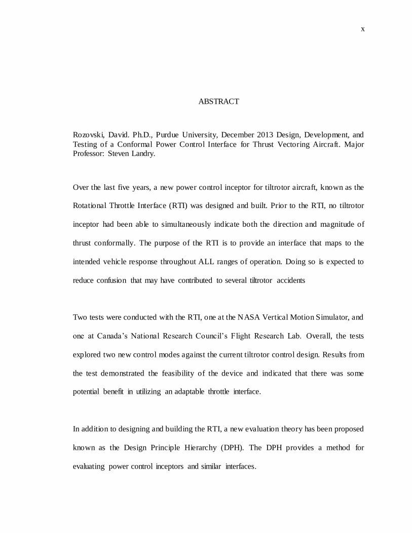
Rozovski, David. Ph.D., Purdue University, December 2013 Design, Development, and
Testing of a Conformal Power Control Interface for Thrust Vectoring Aircraft. Major Professor: Steven Landry.
Over the last five years, a new power control inceptor for tiltrotor aircraft, known as the
Rotational Throttle Interface (RTI) was designed and built. Prior to the RTI, no tiltrotor
inceptor had been able to simultaneously indicate both the direction and magnitude of
thrust conformally. The purpose of the RTI is to provide an interface that maps to the
intended vehicle response throughout ALL ranges of operation. Doing so is expected to
reduce confusion that may have contributed to several tiltrotor accidents
Two tests were conducted with the RTI, one at the NASA Vertical Motion Simulator, and
one at Canada’s National Research Council’s Flight Research Lab. Overall, the tests
explored two new control modes against the current tiltrotor control design. Results from
the test demonstrated the feasibility of the device and indicated that there was some
potential benefit in utilizing an adaptable throttle interface.
In addition to designing and building the RTI, a new evaluation theory has been proposed
known as the Design Principle Hierarchy (DPH). The DPH provides a method for
evaluating power control inceptors and similar interfaces.
1
1
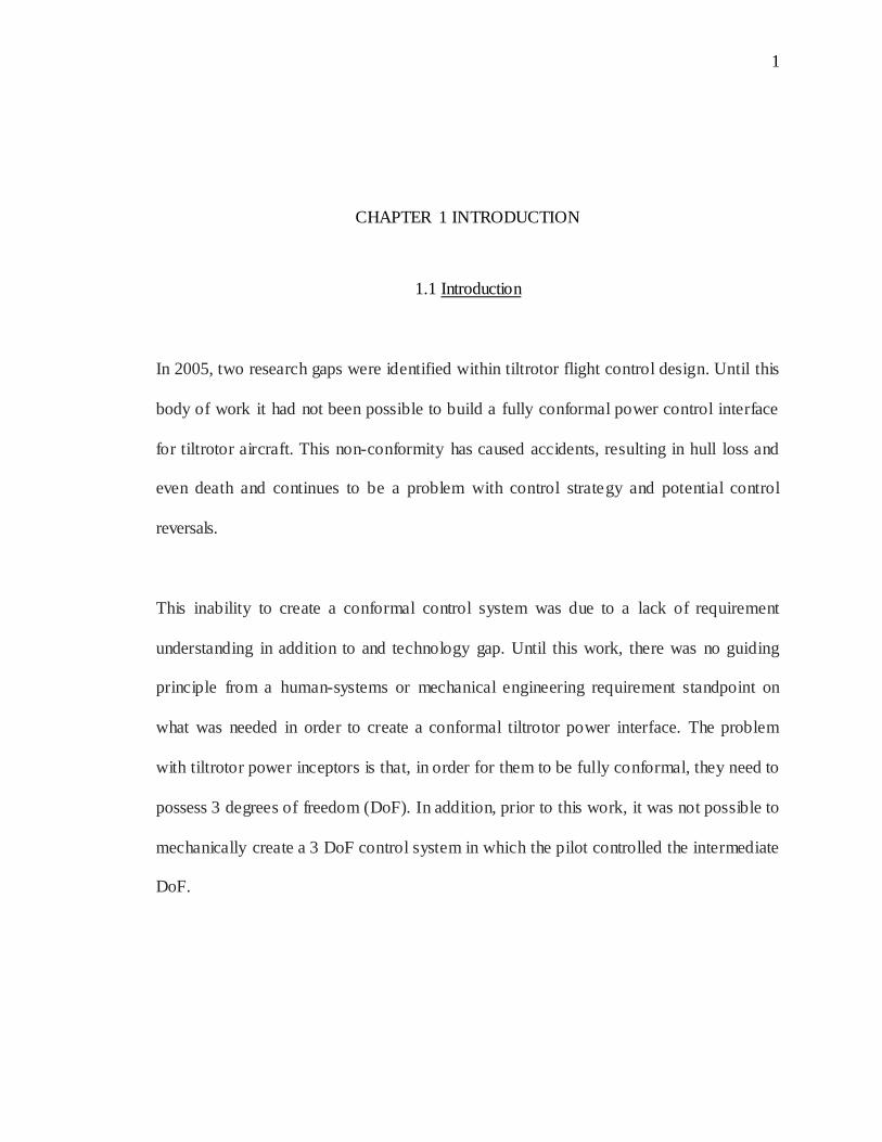
CHAPTER 1 INTRODUCTION
1.1 Introduction
In 2005, two research gaps were identified within tiltrotor flight control design. Until this
body of work it had not been possible to build a fully conformal power control interface
for tiltrotor aircraft. This non-conformity has caused accidents, resulting in hull loss and
even death and continues to be a problem with control strategy and potential control
reversals.
This inability to create a conformal control system was due to a lack of requirement
understanding in addition to and technology gap. Until this work, there was no guiding
principle from a human-systems or mechanical engineering requirement standpoint on
what was needed in order to create a conformal tiltrotor power interface. The problem
with tiltrotor power inceptors is that, in order for them to be fully conformal, they need to
possess 3 degrees of freedom (DoF). In addition, prior to this work, it was not possible to
mechanically create a 3 DoF control system in which the pilot controlled the intermediate
DoF.
2
2
To address both gaps, a new tiltrotor inceptor was designed using a newly proposed
design structure both of which are proposed in this work. RTI construction took
approximately two years. The major technological hurdle in the design was the creation
and implementation of a low weight and robust Concentric Power Transfer Axis (CPTA).
CPTA enables electro-mechanical drive components to be placed downstream and away
from the pilot’s direct interface. This feature reduces the amount of mass the pilot has to
interact with, which in turn improves fine and gross motor accuracy. It is through the
CPTA system that, that for the first time, a third degree of freedom could be
implemented, leading to a fully conformal and congruent tiltrotor power control interface.
To address the design approach principle gap and guide the building of the RTI, the
Design Principle Hierarchy (DPH) was developed. The DPH is intended as a high- level
ordinal and value based system design guide to identify and validate comparative optimal
configurations on both current and future conformal inceptor systems.
Historically controls have been designed to follow cognitive or stimulus-response
mapping (for a detailed discussion of stimulus-response mapping, refer to Proctor & Vu
(2006)). Since all aircraft control systems until the advent of the RTI only possessed 1 or
2 DoFs, this type of purely cognitive or stimulus-response compatibility mapping worked
well as the control movements did not violate ergonomic or other principles. A 3rd DoF
presents itself in tiltrotor power control interfaces, which results in new challenges not
witnessed prior. As inceptor movement complexity increases, the issue of ergonomics,
cognitive mapping, and control strategy, discussed as proprioceptive consistency below,
3
3
become critical. These issues had not previously been addressed, so the creation of a
conformal tiltrotor power control interface was simply not possible. It was only through
the building and testing of the RTI that these additional requirements have been
addressed.
Initial validation of the RTI and DPH was conducted over the course of two experiments:
1. NASA Vertical Motion Simulator (VMS)
2. National Research Council of Canada Flight Research Lab’s (FRL) fixed based
simulator.
Both the VMS and FRL studies were conducted using either trained military test or
research pilots. As the RTI was designed to map to both the direction and magnitude of
thrust, this new drive mode was tested in experimental trials against the current tiltrotor
inceptor baseline. Results from the VMS and FRL studies were conflicting. VMS
findings suggested that the RTI did not prove beneficial to the pilot’s vehicle control.
FRL findings, which occurred after addressing some of the RTI’s mechanical issues,
suggest that the RTI could provide some benefit over the current baseline inceptor.
While additional studies, are needed to conclusively validate both the RTI and DPH, this
work is groundbreaking in that, prior to it, there was no tiltrotor power control interface
that was both conformal and congruently mapped, nor was there a framework that could
guide or evaluate its design.
4
4
1.2 Contribution
The dissertation will make several contributions:
1. Identification of a set of principles for the design of control inceptors;
2. Preliminary evaluations of those principles;
3. The construction of an inceptor for tiltrotor aircraft that conforms to those
principles; which includes the creation and implementation of the CPTA.
The first contribution is expected to have theoretical impact by identifying the cognitive-
ergonomic principles for the design of a tiltrotor power control interface and similar
systems. These principles, if validated, can guide the design of new air vehicle power
inceptors, and may be adopted for use in other vehicles and devices. In addition, these
principles may be used to guide the certification of inceptors in air vehicles.
The inceptor construction and flight simulation testing should have significant practical
implications. It is expected that the new inceptor will be strongly considered as a possible
standard design for tiltrotor vehicles, although additional testing is expected to be needed
in order to confirm its performance benefits. There is clear interest in the inceptor, as
indicated by the support being provided for its design and testing.
In addition, the inceptor design is expected to solve a number of mechanical des ign
problems that have previously prevented its construction, and is expected to represent a
substantial weight savings over current inceptor designs.
The RTI is a fully functional prototype and can be configured to fit into any existing
tiltrotor. In addition to the RTI’s adherence to previously known and newly identified

5
5
human factors principles, the prototype solves several mechanical problems that had
previously defied tiltrotor inceptor designers, all while providing a weight savings of
approximately 10%. (It is expected that the production model would provide an estimated
50% reduction in weight over existing inceptors.)
There are two contributions of this dissertation, both with respect to practical impact and
with respect to the design of controllers for vehicles. This work’s practical impact is
indicated by the interest of members of both the U.S. and Canadian governments, who
have sponsored testing of the device, often at great expense. In addition, the work will
provide better guidance to regulating agencies for the certification of such devices. On a
theoretical level, the proposed research identifies two new critical design principles for
power inceptors, which likely extends to a more general class of controllers.
6
6
CHAPTER 2 BACKGROUND
2.1 Aviation
The design of the control interface is arguably one of the most critical areas of focus in
system design. Without it, or a poor implementation of it, can leave an otherwise ideal
system unmanageable. The first airplane, the Wright Flyer, was the first heavier than air,
powered machine that was able to climb, sustain, and land under its own means. It was
early on that the Wrights recognized the need for proper control.
Even with this recognition, it was not until 1910 that fixed wing flight controls took on
the standardized form that we know today; center stick and rudder pedals/bar. The
creation of what I have coined the Direction and Magnitude Framework (DMF) by
Bleriot in 1910, resulted in the effective and congruent mapping of the flight control
movement to both the vehicle’s intended action and rate at which this intended action will
occur.
With the introduction of the Bell 47 helicopter, 1946 marked the first time the DMF
control configuration was implemented in a different category of aircraft. Since then the
DMF can be found in every Western-certified primary flight control system for both
rotary and fixed wing aircraft.
7
7
Slightly after and parallel to the helicopter’s development, work was initiated by the same
company, Bell, to address the shortcomings of the helicopter’s low forward speed by
combining the positive traits of both the helicopter with its fixed wing counterpart. This
work gave rise to the tiltrotor and after numerous iterations, in 1997, the Bell/Boeing V-
22 Osprey became operational, marking the first mass-produced and certified “tiltrotor”
aircraft.
The Osprey has been plagued with a tumultuous testing history. One of the major issues
faced with the V-22 and prior tiltrotors was how to properly design the power control
interface; should it be a helicopter style collective or a fixed wing style throttle? There
have been numerous iterations, and the current state of the art provides a helicopter style
collective for the civilian Agusta-Westland 609 and an airplane style throttle for the V-22
Osprey.
The final in the case of the V-22 power control interface iteration occurred after three
separate attempts, moving from a collective to a Harrier- like throttle known as the Blotle,
and finally to a six- inch linear throttle similar to those found in fixed wing aircraft. The
evolution of the V-22s power control interface is described in detail later on, but it is
important to highlight that at least one of these transitions was the result o f a crash during
flight test is due at least in part to a design flaw in the control system design (Dugan,
1998). Tiltrotor control systems are unique in that they are one of the few vehicle systems
in the world that have a multi Degree-of-Freedom (DoF) control system.
8
8
Aircraft are extremely unforgiving by nature. In addition to their complexity, it is one of
the only environments in the world where, when things go awry, operators cannot stop
the system to deal with the malfunction. This quality only further compounds the
necessity for proper system and control design.
One can identify many “control levels” of aviation systems beginning with primary basic
control of attitude and power all the way to advanced envelope protection and automated
system management and navigation. While the intermediate levels are expansive, without
a proper foundation in control design, the aircraft, no matter how advanced and
automated it is, can still be rendered ineffective if its system design foundation is weak.
An example of this effect is the control design lag that was found in the initial F-22
Raptor prototype. The control system suffered a relatively small delay from input to
output, on the order of a couple of hundred milliseconds. This, however, was enough for
the pilot’s control bandwidth to exceed the vehicle’s response bandwidth leading to a
Pilot Induced Oscillation (PIO). The PIO event occurred proximal to the ground and
nearly destroyed the aircraft and pilot. The F-22 is one of the most advanced and modern
fighter in the world today, yet a simple delay in the control system nearly left this 5th
generation fighter uncontrollable. This is one example that illustrates the fundamental
importance of proper control design from the ground up.
Today’s aviation control design standards are incredibly well defined with a few
exceptions. One would be hard pressed to find freedoms within the current design

9
9
regulations and guidelines. This has led to a very predicable set of design practices that
can be seen in every modern aircraft since the late ‘40s. While these design practices are
relatively long lived within the existence of aviation, there was a period of time where
flight control design standards where vastly different.
2.2 Flight Control History
The first flight of a powered, heavier than air vehicle occurred at Kitty Hawk on
December 1903 by Orville Wright in the Wright Flyer I. This aircraft used a sliding hip
holster and forward/aft moving controls in order to control roll through wing warping,
and pitch through a canard stabilator. Over the next 7 years, a variety of configurations
were attempted but it was not until 1910, when Bleriot began designing his aircraft, that
the current standard of a center stick and rudder pedal/bar configuration was adopted.
The move to this control design configuration began what today is considered the
standard in aircraft control configuration. By using a center stick and rudder pedal
configuration (Figure 1), the controls directly indicate two very important pieces of
information to the pilot, the direction and magnitude of intended control response.
Another way to state this is that the controls themselves indicate both the direction and
the magnitude (rate) at which the vehicle should respond. This contribution adheres to
what will be referred to in the dissertation as the Direction and Magnitude Framework
(DMF). Another implementation of the center stick is the control yoke configuration that
serves the same purpose with respect to vehicle control and also indicates the same
information to the pilot.

10
10
Figure 1. Center Stick and Rudder Pedal Configuration.
While airplanes have been present the longest of all the heavier than air powered vehicles,
The DMF design implementation has affected every other type of powered heavier than
air vehicle since the transition to a standard set of controls. Even helicopters, which fall
under an entirely different category of aircraft, have been influenced by the DMF and
adhere to this standard.
The DMF became so prevalent that the FAA made specific note of it in Aeronautical
Design Standard parts 23.779, 25.779, 27.779, and 29.779 for normal category fixed
11
11
wing, transport category fixed wing, normal category helicopters, and transport category
helicopters respectively.
This implementation and standardization of control design that ind icates both the
intended vector and magnitude of the aircraft provides a variety of benefits. Positive
transfer of training is promoted due to both the stimulus and response elements being
similar across platforms allowing pilots to transition from one type or category to another
without learning entirely new control schemas (Wickens & Hollands, 2000). Because the
control movements themselves map congruently to the aircraft’s intended response, there
are fewer mental transformations required by the pilot to execute the intended action, thus
allowing for an indirect reduction in workload.
In accordance with the above schema, power control systems also have had FAA design
mandates placed upon them. In fixed wing aircraft, under FAA parts 23 and 25, specific
mention is given to the direction of the throttle (power lever) that it must move forward
(with respect to the aircraft’s firewall) in order to increase power and backwards in order
to decrease. In helicopters, FAA parts 27 and 29 referred to above, require the collective
(power lever) to move up (with respect to the helicopter’s horizontal plane) to add power
and down to reduce it.
12
12
2.3 Tiltrotor History
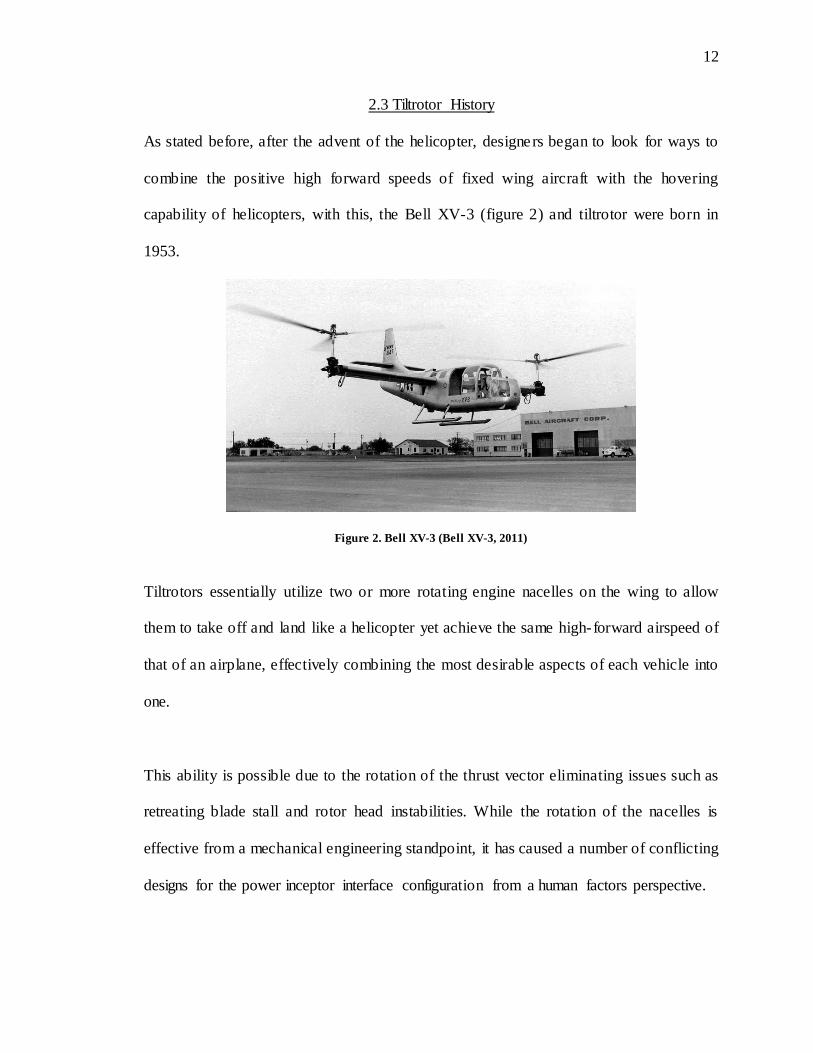
As stated before, after the advent of the helicopter, designers began to look for ways to
combine the positive high forward speeds of fixed wing aircraft with the hovering
capability of helicopters, with this, the Bell XV-3 (figure 2) and tiltrotor were born in
1953.
Figure 2. Bell XV-3 (Bell XV-3, 2011)
Tiltrotors essentially utilize two or more rotating engine nacelles on the wing to allow
them to take off and land like a helicopter yet achieve the same high-forward airspeed of
that of an airplane, effectively combining the most desirable aspects of each vehicle into
one.
This ability is possible due to the rotation of the thrust vector eliminating issues such as
retreating blade stall and rotor head instabilities. While the rotation of the nacelles is
effective from a mechanical engineering standpoint, it has caused a number of conflicting
designs for the power inceptor interface configuration from a human factors perspective.

13
13
The conflict has been driven by the additional degree of freedom thrust the tiltrotor power
vector possess. Until tiltrotor aircraft, all power control systems operated on a single
degree of freedom since the thrust vector direction remained constant. The difference in
these designs existed between fixed-wing and rotary-wing aircraft. The conflict arose
with tiltrotors power control design in whether they followed the convention of an
airplane, whose thrust axis is “forward-aft” from the perspective of the pilot, or a
helicopter, whose thrust axis is primarily “up-down”, (See Figure 3). As both airplane
and helicopter power control interfaces are fixed, they both present incongruences during
different phases of tiltrotor operation. Concrete examples include an airplane style
throttle when the tiltrotor is in helicopter mode (i.e. nacelles pointed up) or a helicopter
style collective when in airplane mode (i.e. nacelles pointed forward).
Figure 3. Airplane Throttle (left) and Helicopter Collective (right) (Rozovski, 2008a)
Because of the tiltrotors unique ability to morph (i.e. rotate its thrust vector), there have
been many attempts to determine the most appropriate inceptor/interface type for tiltrotor
aircraft. The XV-3, discussed above and shown in figure 2, was the first functioning
tiltrotor and utilized a helicopter collective style inceptor interface to control the engines.

14
14
Because the XV-3’s blades were taken from a conventional helicopter, they did not have
the required chord twist (pitch) in the blades in order to make them suitable for both
forward and vertical flight. Because of this limitation, the XV-3 pilot had a switch on the
collective that allowed the pilot to control pitch range of the blades essentially remapping
the collective to both helicopter and airplane mode. Even with this added control, the
XV-3 presented incongruencies in airplane mode as the collective could not rotate in
order to match the nacelle angle. The system, while aerodynamically effective, proved to
be cumbersome for the pilot and was further compounded by the aircraft’s marginal
handling qualities, which were further compounded by its lack of power. In one flight test
report, the complication of the control system was one of four primary critiques of the
vehicle due to its cumbersome complexity (Deckert & Ferry, 1960).
With both the success and shortcomings of the XV-3, other companies saw the potential
for a tiltrotor or tiltwing concept. In early 1960’s Ling-Temco-Vought (LTV) began
experimental flight testing on the LTV XC-142. While a tiltwing as opposed to a tiltrotor,
the idea was similar in that it was designed to combine the positive traits of both a
helicopter and airplane into a single vehicle.
Even in the early 1960s when the aircraft was being built, there was still uncertainty as to
the most appropriate design for a power control inceptor interface for tilt-rotor/wing
aircraft. In the case of the XC-142, designers decided that both throttles and collectives
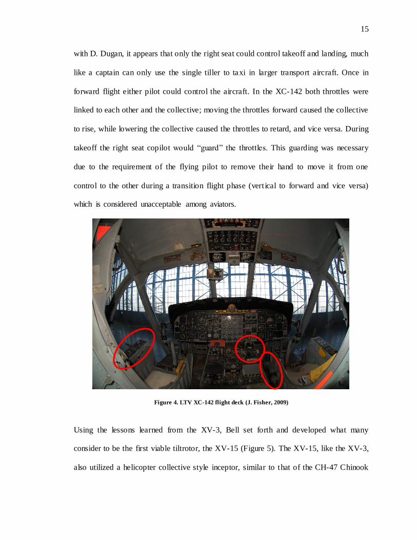
should be present. As viewed in the figure 4 the right seat pilot had both a collective and
set of throttles while the left seat pilot only had throttles. From personal communication
15
15
with D. Dugan, it appears that only the right seat could control takeoff and landing, much
like a captain can only use the single tiller to taxi in larger transport aircraft. Once in
forward flight either pilot could control the aircraft. In the XC-142 both throttles were
linked to each other and the collective; moving the throttles forward caused the collective
to rise, while lowering the collective caused the throttles to retard, and vice versa. During
takeoff the right seat copilot would “guard” the throttles. This guarding was necessary
due to the requirement of the flying pilot to remove their hand to move it from one
control to the other during a transition flight phase (vertical to forward and vice versa)
which is considered unacceptable among aviators.
Figure 4. LTV XC-142 flight deck (J. Fisher, 2009)
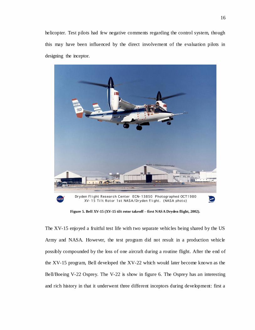
Using the lessons learned from the XV-3, Bell set forth and developed what many
consider to be the first viable tiltrotor, the XV-15 (Figure 5). The XV-15, like the XV-3,
also utilized a helicopter collective style inceptor, similar to that of the CH-47 Chinook
16
16
helicopter. Test pilots had few negative comments regarding the control system, though
this may have been influenced by the direct involvement of the evaluation pilots in
designing the inceptor.
Figure 5. Bell XV-15 (XV-15 tilt rotor takeoff – first NASA Dryden flight, 2002).
The XV-15 enjoyed a fruitful test life with two separate vehicles being shared by the US
Army and NASA. However, the test program did not result in a production vehicle
possibly compounded by the loss of one aircraft during a routine flight. After the end of
the XV-15 program, Bell developed the XV-22 which would later become known as the
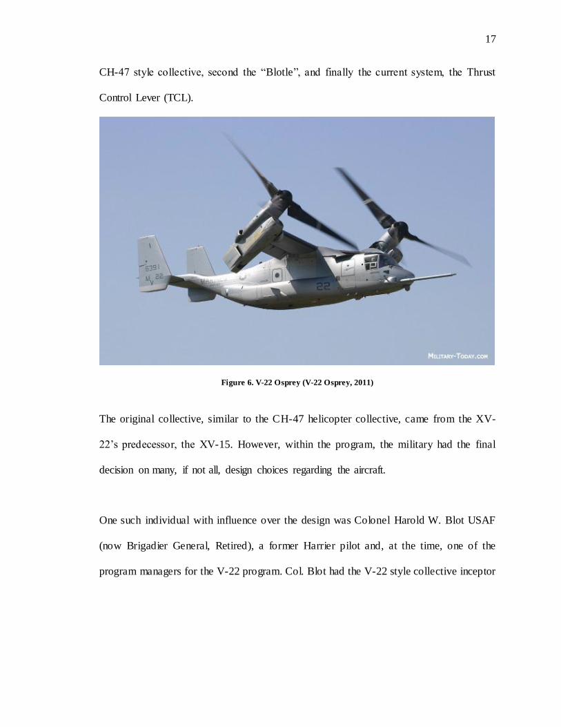
Bell/Boeing V-22 Osprey. The V-22 is show in figure 6. The Osprey has an interesting
and rich history in that it underwent three different inceptors during development: first a
17
17
CH-47 style collective, second the “Blotle”, and finally the current system, the Thrust
Control Lever (TCL).
Figure 6. V-22 Osprey (V-22 Osprey, 2011)
The original collective, similar to the CH-47 helicopter collective, came from the XV-
22’s predecessor, the XV-15. However, within the program, the military had the final
decision on many, if not all, design choices regarding the aircraft.
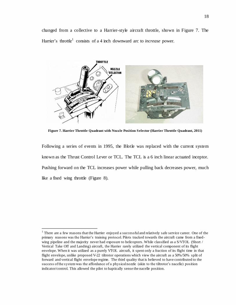
One such individual with influence over the design was Colonel Harold W. Blot USAF
(now Brigadier General, Retired), a former Harrier pilot and, at the time, one of the
program managers for the V-22 program. Col. Blot had the V-22 style collective inceptor
18
18
changed from a collective to a Harrier-style aircraft throttle, shown in Figure 7. The
Harrier’s throttle1 consists of a 4 inch downward arc to increase power.
Figure 7. Harrier Throttle Quadrant with Nozzle Position Selector (Harrier Throttle Quadrant, 2011)
Following a series of events in 1995, the Blotle was replaced with the current system
known as the Thrust Control Lever or TCL. The TCL is a 6 inch linear actuated inceptor.
Pushing forward on the TCL increases power while pulling back decreases power, much
like a fixed wing throttle (Figure 8).
1 There are a few reasons that the Harrier enjoyed a successful and relatively safe service career. One of the
primary reasons was the Harrier’s training protocol. Pilots tracked towards the aircraft came from a fixed-
wing pipeline and the majority never had exposure to helicopters. While classified as a S/VTOL (Short /
Vertical Take Off and Landing) aircraft, the Harrier rarely utilized the vertical component of its flight
envelope. When it was utilized as a purely VTOL aircraft, it spent only a fraction of its flight time in that
flight envelope, unlike proposed V-22 tiltrotor operations which view the aircraft as a 50%/50% split of
forward and vertical flight envelope regime. The third quality that is believed to have contributed to the
success of the system was the affordance of a physical nozzle (akin to the tiltrotor’s nacelle) position
indicator/control. This allowed the pilot to haptically sense the nacelle position.

19
19
Figure 8. Current V-22 power inceptor (Source Unknown)
Parallel to the development of the Bell/Boeing V-22, Bell had also teamed up with
Boeing to create the first civilian certified tiltrotor, the 609, shown in Figure 9. Since the
initial partnership, the Boeing sold its share of the 609 to Agusta who since then has
purchased the 609 outright turning it into the Agusta-Westland or AW 609. The AW-609
is a 7-11 seat tiltrotor designed for executive transport and possible Search and Rescue
(SAR) missions.
Figure 9. BA609 in nacelle up position (90o) and nacelle forward position (0o) (BA609 Images, 2008)
While the V-22 and AW-609 are similar in their configuration, method of operation, and
even flight controls, the AW-609 possesses a helicopter collective style power inceptor
20
20
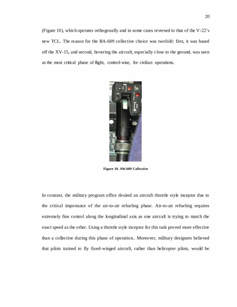
(Figure 10), which operates orthogonally and in some cases reversed to that of the V-22’s
new TCL. The reason for the BA-609 collective choice was twofold: first, it was based
off the XV-15, and second, hovering the aircraft, especially close to the ground, was seen
as the most critical phase of flight, control-wise, for civilian operations.
Figure 10. AW-609 Collective
In contrast, the military program office desired an aircraft throttle style inceptor due to
the critical importance of the air-to-air refueling phase. Air-to-air refueling requires
extremely fine control along the longitudinal axis as one aircraft is trying to match the
exact speed as the other. Using a throttle style inceptor for this task proved more effective
than a collective during this phase of operation.. Moreover, military designers believed
that pilots trained to fly fixed-winged aircraft, rather than helicopter pilots, would be
21
21
transitioned to fly the V-22, making a throttle a more familiar control design, in
retrospect more helicopter pilots have transitioned.
2.4 Consequences
With the design progression of the XV-3 through the V-22 and AW-609, there are a
multitude of consequences that have resulted from the design selections implemented
within each platform (i.e. V-22, AW-609) as well as across them. While design mandates
exist for current vehicle categories such as fixed and rotary wing aircraft, there is little to
no documentation on what the standard should be from a certification or even human
factors perspective on new categories of aircraft such as tiltrotors. By implementing
either a fixed-wing or rotary-wing control interface in a tiltrotor, compromises have to be
made. One system could work well in one flight mode while the other system may work
equally as well in the helicopter mode. Depending on the control style selection, either
these choices can violate stimulus-response (S-R) compatibility in the alternate mode of
which can result in negative transfer of training, can be ergonomically incorrect, and/or
can result in proprioceptive inconsistencies. (The first two principles are established in
human factors literature, the latter two are discussed as part of this dissertation).
2.5 Theoretical Overview Established from Master’s Thesis
S-R compatibility dictates that the intended input should map appropriately to the
intended system response (Fitts & Seeger, 1953). By following this principal, the number
of mental transformations are kept to a minimum and performance should increase
22
22
accordingly relative to a system in which the principal is violated. S-R compatibility is
well-established as critical to good control performance (Proctor & Reeve, 1990).
During the initial development of the DPH and RTI design framework, Stimulus
Response (S-R) Compatibility was used as a guiding stepping-stone. While direct
parallels do not exist between the S-R body of work and off-axis back-driven continuous
control system interfaces, there are applicable take-aways that exist.
Even prior to the development of the tiltrotor itself, work had initiated on relevant issues
that would have far reaching implications on not just aircraft, but all vehicle controls.
Andre, Haskell, and Wickens (1991) noted the importance of compatibility in orthogonal
control systems, specifically calling out aviation. Bertelson (1963) looked at the issue of
orthogonality a few years after the development of the first tiltrotor, although he did not
specifically address aviation; his study focused on orthogonal stimulus response across
perpendicular alignments. Another study conducted by Vince and Mitchel (1946)
focused on participant manipulation of a continuous control interface left to right to
control a vertically aligned continuous display, and found a preference for right to up
pairing.
In all, S-R compatibility has attachments to the DPH and RTI as a parallel though it was
never the intent of this work to expand the S-R body of work. This said, S-R was drawn
in to illustrate one of the feature sets that the RTI and DPH encompass, at a basic level,
the idea or notion that items respond in congruence with the direction of their actioned
23
23
input (i.e. the Direction and Magnitude Framework (DMF)). For a more complete
discussion of Stimulus Response Compatibility, Proctor and Vu’s Stimulus-Response
Compatibility Principles (Proctor & Vu, 2006) offers an excellent foundation on S-R
Compatibility and where the science stands today.
Violations of these principles can result in “negative transfer”, where negative transfer is
defined as “one set of task skills interfering with another set of task skills within the same
environment” (Wickens & Hollands, 2000). In other words, pilots used to flying a
helicopter power inceptor (collective) would demonstrate difficulty utilizing an airplane
power inceptor (throttle) while flying and vice versa.
Negative transfer can lead to increased training costs, pilot error, and even accidents. Due
to a variety of factors, the majority of the pilots transitioning to the V-22 are coming from
a helicopter pipeline. Because of the orthogonality between the control strategies of a
helicopter collective and the V-22’s throttle, it is currently estimated that pilots are
spending 10-100 hours on average in order to relearn the new control strategy for adding
power (Cantrell, 2007). It is this same orthogonality that is thought to cause control
reversals, which can cause pilot error and accidents.
The potential for error and accident due to control reversal problems was demonstrated
by the crash of a V-22 in 1995 when Air Force V-22 vehicle #5 was lost approximately
49 seconds into flight. The controls of vehicle #5, whose inceptor (the Blotle; downward
4-inch arcing travel path) followed the fixed-wing convention, had had two of its three
24
24
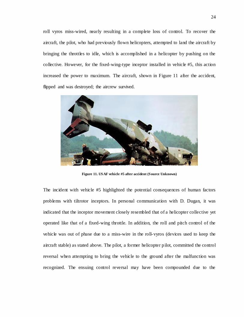
roll vyros miss-wired, nearly resulting in a complete loss of control. To recover the
aircraft, the pilot, who had previously flown helicopters, attempted to land the aircraft by
bringing the throttles to idle, which is accomplished in a helicopter by pushing on the
collective. However, for the fixed-wing-type inceptor installed in vehicle #5, this action
increased the power to maximum. The aircraft, shown in Figure 11 after the accident,
flipped and was destroyed; the aircrew survived.
Figure 11. USAF vehicle #5 after accident (Source Unknown)
The incident with vehicle #5 highlighted the potential consequences of human factors
problems with tiltrotor inceptors. In personal communication with D. Dugan, it was
indicated that the inceptor movement closely resembled that of a helicopter collective yet
operated like that of a fixed-wing throttle. In addition, the roll and pitch control of the
vehicle was out of phase due to a miss-wire in the roll-vyros (devices used to keep the
aircraft stable) as stated above. The pilot, a former helicopter pilot, committed the control
reversal when attempting to bring the vehicle to the ground after the malfunction was
recognized. The ensuing control reversal may have been compounded due to the
25
25
associated workload of the faulty vyros. It was after this incident that the Blotle was
removed and replaced with a 6-inch linear throw throttle.
In order to prevent such incidents in the future, it is necessary, and the goal of this work,
to identify a design for tiltrotor inceptors consistent with human factors best-practice
principles. More generally it is necessary to understand how to drive design evolution to
address continuous control systems that possesses more than 2 degrees of freedom.
2.6 Initial Design Principle Hierarchy
While design mandates in control interfaces exist (FAR regulations), they dictate the
direction of movement of the control interface. While this may work for the majority if
not all current aircraft flight controls, tiltrotor aircraft present a unique challenge in that
their power control inceptor possesses an additional 3rd Degree of Freedom (DoF).
Utilizing current fixed wing or helicopter has proven to be problematic (Dugan, 1998,
Deckert & Ferry, 1960).
Initially, it was believed that only cognitive mapping, effectively the compatibility
between the inceptor’s movement and the effected action, was the critical characteristic.
After some analysis however, it was deemed not to be the case as there are many
successful control interfaces in the world that do not adhere to cognitive mapping
consistent with S-R Compatibility.
26
26
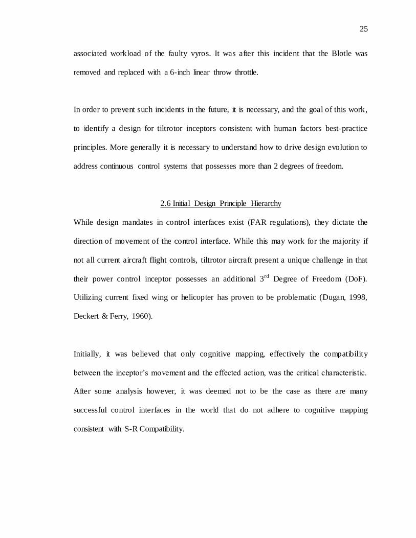
One example of such an interface is the motorcycle throttle control grip (Figure 12). A
motorcycle throttle grip adds power to the system by rolling the top portion of the throttle
aft towards the operator. From the standpoint of human factors, this appears to violate the
principle the stimulus-response compatibility as the motorcycle is propelled in the
opposite direction of the movement of the grip. Moreover motorcycle throttle designs
have not varied in over 50 years and are considered a standard for such vehicles.
Figure 12. Motorcycle throttle grip
In looking at the motorcycle throttle grip further, it was noted that a grip that did meet S-
R compatibility requirement (i.e., top portion rolls forward) would be extremely
uncomfortable. The reason for this being that it would not be ergonomic.
In order to explain the motorcycle throttle grip, both principles were combined giving rise
to the Design Principle Hierarchy or DPH. The DPH was structured as a list of
requirements, as follows:
1. Ergonomics
2. Cognitive Mapping

27
27
The DPH initially was designed as an ordinal system in that each level had to be met
prior to moving on to the next level. In the case of the motorcycle throttle grip, the
ergonomic level was met prior to the cognitive mapping requirement, resulting in a
successful control interface.
28
28
CHAPTER 3 PRIOR WORK ON TILTROTOR INCEPTORS
An interface known as the Rotational Throttle Interface or RTI was developed based on
the DPH. The RTI was able to rotate and map congruently to both the magnitude of
commanded engine thrust and the direction at which this thrust was vectored in tiltrotor
aircraft.
For the design the cognitive-ergonomic requirements were set forth as well as the design
methodology, specification, and requirements for the RTI. This information is presented
in my University of Illinois Master’s Thesis titled “Control Reversal Mitigation and
Situational Awareness Improvement for Tiltrotor Aircraft Pilots via Redesign of the
Thrust/Power Control Interface”. In addition to the document, a plastic stereo- lithography
non-functional RTI prototype was created to do ergonometric evaluations of the system’s
discrete movements and position placement.
3.1 History of Mapping Power Inceptors
While indicated above that the high- level RTI design was accomplished during the
Master’s thesis, it is important to gain an understanding of what has been done prior
regarding map-able throttle design for tiltrotor aircraft. The concept behind a map-able
throttle system is to provide the pilot both an indication of magnitude and direction of

29
29
intended aircraft action. Because tiltrotor aircraft can vary the angle of their engines an
additional degree of freedom is needed in order to accurately depict the engine vector in
this type of inceptor. To date there have been three map-able throttle systems, including
the RTI (chronological order in parenthesis):
1. The Magnum developed by Jim Cheatham (1st)
2. Haverdings’ system out of the Netherlands (3rd)
3. The Rotational Throttle Interface or RTI (2nd)
All three of these systems have been developed independently of a field-able aircraft
design but were specifically designed to address the additional DoF found in tiltrotor
aircraft. This is an important characteristic, as the goal of these three projects was to
standardize tiltrotor power inceptor interface design.
3.1.1 Magnum
The first independent system, known as the Magnum, was designed by Jim Cheatham.
(The name “Magnum” was a tribute to Clint Eastwood, who was one of the first private
investors in civil tiltrotors (D. Dugan personal communication)) Figure 13 a-c depicts the
orientation of the Magnum in reference to the nacelle angles depicted by the model. (The
transposition of figure 13a relative to figures 13b and 13c is unfortunate, but these are the
only three known sequential photos of the Magnum through its full envelope travel range.)
The important design characteristic of the Magnum is the selected pivot point of the unit.
In Figure 13a, the Magnum operates as a collective: as the nacelles rotate forward the
30
30
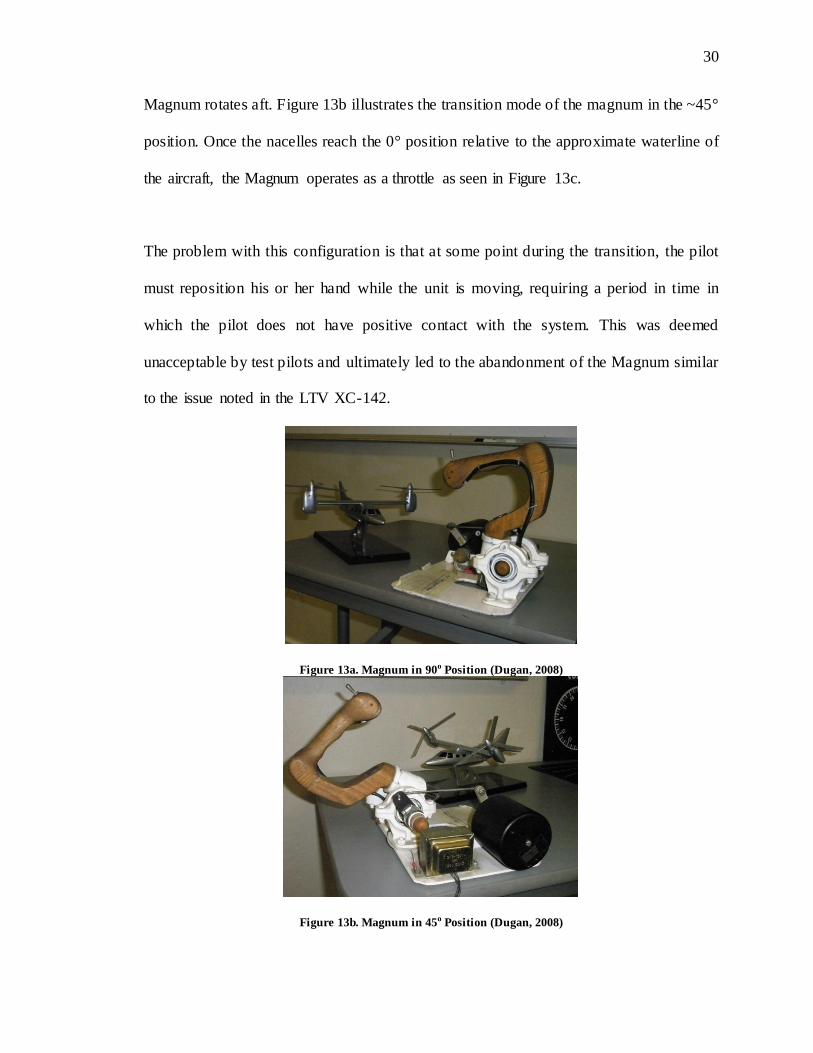
Magnum rotates aft. Figure 13b illustrates the transition mode of the magnum in the ~45°
position. Once the nacelles reach the 0° position relative to the approximate waterline of
the aircraft, the Magnum operates as a throttle as seen in Figure 13c.
The problem with this configuration is that at some point during the transition, the pilot
must reposition his or her hand while the unit is moving, requiring a period in time in
which the pilot does not have positive contact with the system. This was deemed
unacceptable by test pilots and ultimately led to the abandonment of the Magnum similar
to the issue noted in the LTV XC-142.
Figure 13a. Magnum in 90o Position (Dugan, 2008)
Figure 13b. Magnum in 45o Position (Dugan, 2008)
31
31
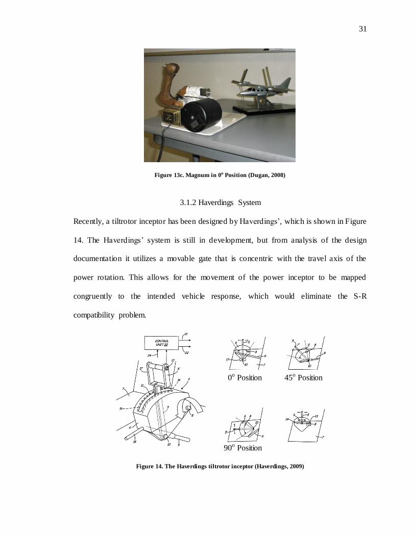
Figure 13c. Magnum in 0o Position (Dugan, 2008)
3.1.2 Haverdings System
Recently, a tiltrotor inceptor has been designed by Haverdings’, which is shown in Figure
14. The Haverdings’ system is still in development, but from analysis of the design
documentation it utilizes a movable gate that is concentric with the travel axis of the
power rotation. This allows for the movement of the power inceptor to be mapped
congruently to the intended vehicle response, which would eliminate the S-R
compatibility problem.
Figure 14. The Haverdings tiltrotor inceptor (Haverdings, 2009)
0o Position
90o Position
45o Position
32
32
However, due to the co- locality of the inceptor and gate movement axis, the pilot has no
way to discern the difference between their own input vs. a nacelle movement. This
sharing of movement axes can cause cross coupling during nacelle transition and power
adjustments, making the pilot unable to discern haptically which component of the
system is moving.
Haverdings’ system presents interesting design choices in that the throttle pos ition is
measured relative to the moving gate. The moving gate is floating and provides no anchor
point to the pilot in reference to throttle position. Pilots can discern neither the current
flight envelope nor the nacelle position/movement without moving full aft and full
forward to interpolate the plane of travel. This interpolation is not only difficult to
imagine, but also nearly impossible to do due to the lack of angular sensitivity of the
pilot’s hand through the forearm and upper arm.
3.1.3 Rotational Throttle Interface
Prior to public disclosure of the design of the Haverdings’ system, development of the
RTI had begun, and a patent had been filed on the design (Haverding, 2009). The
question that emerged for me from the crash of V-22 USAF vehicle #5 was, “why would
a highly trained test pilot commit a control reversal in a vehicle with which they were
apparently familiar?” This ultimately led to a question about what the most appropriate
inceptor is for tiltrotor aircraft.
33
33
3.2 Genesis of the Rotational Throttle Interface
The development of the RTI was guided in part by three systems:
1. Fixed-wing power inceptors
2. Rotary-wing power inceptors
3. Jim Cheatem’s Magnum system
In order to gain a better understanding of what was required to develop a map-able
throttle interface for tiltrotor aircraft, I conducted a complete task analysis of the power
control strategy for both helicopters and airplanes. The logic behind this was that a
tiltrotor was a combination of both vehicle types and the uniqueness of the tiltrotor
system was presented in the intermediate envelope (i.e. the transition phase). That is, if
the intermediate range was the unique component, then gaining a better understanding of
the discrete extreme points of the envelope (i.e. fixed-wing horizontal mode and rotary-
wing vertical mode) would allow for better interpolation of what was needed in-between.
As described previously, both helicopters and airplanes have power inceptors that map
congruently to their intended aircraft response respectively. This congruent mapping is
not a necessary function of the aircraft per se but rather a function of years of
standardization across different categories of aircraft, and is consistent with SR
Compatibility.
This standardization can actually be traced back to 1946 with the marking of two
important events, the first commercially certified helicopter and the creation of the
34
34
direction-magnitude framework (DMF). The DMF is defined as the direction and
displacement amplitude of the control inceptor being directly indicative of the vehicles
response. This means that the direction of the control inceptor displacement is matched to
the vehicle’s response, such that as displacement of the inceptor increases, the faster the
vehicle will move in said direction. The DMF is believed to apply to all controls, not just
the power inceptors that are the focus of this proposal.
Concrete examples of the DMF can be found in every type of fixed and rotary wing
aircraft certified since 1946. Figure 1 illustrates the center stick/cyclic and rudder/tail
rotor pedals found in fixed and rotary wing aircraft respectively which follow the DMF
frame work.
All of these primary controls follow the idea of intended action vector depiction
described above. This requirement is actually indirectly mandated in part 23, 25, 27, and
29 subpart .779 certification standards of the Federal Aviation Administration:
FAR Part §23.779: Motion and Effect of Cockpit Controls (Airworthiness
Standards: Normal, Utility, Aerobatic, and Commuter Category Airlines, 1996)
(a) (1) Primary Control:
Aileron; Right (clockwise) for right wing down.
Elevator; Rearward for nose up.
Rudder; Right pedal forward for nose right.
35
35
(b) (1) Powerplant Controls:
Power or Thrust; Forward to increase forward thrust and rearward to
increase rearward thrust.
Propellers; Forward to increase rpm.
FAR Part §25.779: Motion and Effect of Cockpit Controls (Airworthiness
Standards: Transport Category Airlines, 1990)
(a) (1) Primary Control:
Aileron; Right (clockwise) for right wing down.
Elevator; Rearward for nose up.
Rudder; Right pedal forward for nose right.
(b) (1) Powerplant Controls:
Power or Thrust; Forward to increase forward thrust and rearward to
increase rearward thrust.
Propellers; Forward to increase rpm.
FAR Part §27.779: Motion and Effect of Cockpit Controls
(Airworthiness Standards: Normal Category Rotorcraft, 1984)
(D) (a) Flight controls, including the collective pitch control, must operate
with a sense of motion which corresponds to the effect on the rotorcraft.
36
36
FAR Part §29.779: Motion and Effect of Cockpit Controls
(Airworthiness Standards: Transport Category Rotorcraft, 1984)
(D) (a) Flight Controls, including the collective pitch control:
Must operate with a sense of motion which corresponds to the
effect on the rotorcraft.
While the primary three-axis (roll, pitch, and yaw) controls are identical in both fixed and
rotary wing aircraft, the power control inceptors vary greatly, so much so that the controls
are orthogonal and even reversed in many cases when compared to each other (fixed to
rotary wing). However, even with this difference, each aircraft is able to indicate the
intended vector of action through its control system.
Fixed wing aircraft utilize a throttle oriented along the x-axis in a body-fixed and stability
control coordinate system. Helicopters utilize a collective oriented along the z-axis in a
body-fixed and stability control coordinate system. While there are differences, neither a
fixed wing throttle nor rotary wing collective violates the intended vector or response
concept as described above as they each move in the direction of the intended aircraft
response respectively.
The importance of this standardization is significant. It is this standardization of controls
that allows pilots transitioning from one type of aircraft to another to complete only a
“differences training” without having to relearn the fundamentals of flight. This
standardization found in control design can be seen across almost every mainstream
37
37
vehicle in the western world, including automobiles, motorcycles, boats, airplanes, and
helicopters.
While this standardization has been in place for over 50 years either in practice or as a
request, it seemed logical that building the RTI within these confines would yield the
most positive results. Therefore, emphasis was given to inceptor design techniques that
would minimize the associated learning curve of the new RTI. The RTI had to be
consistent with both helicopter and aircraft inceptors, and it was believed that it also had
to map to the tiltrotor’s intended response throughout all flight envelopes. The system
that resulted was a throttle interface in which the linear axis of throttle travel, common in
both airplanes and helicopters, rotated in order to account for the added degree of
freedom of the nacelle movement.
While the initial design of the RTI is fully documented in my Master’s thesis (Rozovski,
2008a), it is important to have an understanding of the high- level design requirements.
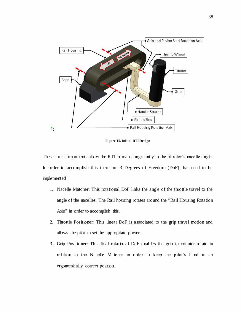
Figure 15 depicts the initial RTI base prototype model. While all parts are labeled, the
items of most importance are:
1. Rail Housing Rotation Axis
2. Rail Housing
3. Grip and Pinion Sled Rotation Axis
4. Grip
38
38
Figure 15. Initial RTI Design
These four components allow the RTI to map congruently to the tiltrotor’s nacelle angle.
In order to accomplish this there are 3 Degrees of Freedom (DoF) that need to be
implemented:
1. Nacelle Matcher; This rotational DoF links the angle of the throttle travel to the
angle of the nacelles. The Rail housing rotates around the “Rail Housing Rotation
Axis” in order to accomplish this.
2. Throttle Positioner: This linear DoF is associated to the grip travel motion and
allows the pilot to set the appropriate power.
3. Grip Positioner: This final rotational DoF enables the grip to counter-rotate in
relation to the Nacelle Matcher in order to keep the pilot’s hand in an
ergonomically correct position.

39
39
Figure 16 depicts a discretized composite graphic of the RTI rotating in relationship to
the nacelle angle.
Figure 16. RTI in 950, 900, 450, and 00 position.
As noted in graphic 16, it is easy to see how the top of the grip rotates aft (in relationship
to the aircraft) as the rail housing rotates forward.
40
40
CHAPTER 4 ROTATIONAL THROTTLE INTERFACE
Moving from the high- level non-functional prototype to a fully functional testable system
was a significant challenge. There were multiple phases to this process. The initial RTI
design requirements were as follows:
1. Meet all ergonomic requirements (necessary in order to satisfy level 1 of the DPH)
2. Allow the RTI to map congruently to the full nacelle range (Level 2 DPH)
3. Ability to interface to off- the-shelf flight simulators (X-Plane (Digital) was
chosen)
4. Ability to interface to future flight simulation systems (i.e. NASA Vertical
Motion Simulator (Analog)
5. Meet or fall below current tilt rotor throttle interface system weight (80 lbs.)
6. Address failure modes which had to be mitigated and completely accounted for.
In order to develop the full system, an independent electrical engineer and independent
engineering draftsman where hired through an external source mechanism.
41
41
4.1 Electrical-Mechanical Design
Due to the limited funding nature of the project, it was decided early on to implement
Certified-Off-The-Shelf (COTS) components as much as possible. This was done in order
to reduce the development cost of custom components
Of the six guidance requirements listed above, items 2, 3, 4, and 6 were focused on the
electromechanical design phase. In satisfying item 2, allowing the RTI to map
congruently to the full nacelle range, some form of actuation was needed. The two
choices that were available were stepper motors and servos. In looking at the cost/benefit
analysis between the two, it was deemed that the use, cost, complexity, and programming
of a stepper motor was significantly less than that of a servo of equal size and capacity. In
addition to this, stepper motors provided significantly higher movement and holding
torque than an equivalently sized and priced servo translating to a smaller actuation
system footprint.
To minimize cost further, two identical COTS industrial grade stepper motors and drive
control units where selected to drive the RTI. The units themselves were highly available,
they were very easy to program, a single size was available that could drive both the rail
housing and grip rotation without having to have different sized motors or drive units.
In order to meet requirement 3, the ability to interface to off-the-shelf flight simulators, I
implemented a USB Analog to Digital (A to D) interface. The electromechanical system
could then be driven using a standard personal computer running Windows 7 interfaced
42
42
through a small C++ software module interfaced to Laminar Research’s X-Plane 9 for the
flight math model.
One of the added benefits of placing an A to D interface between the system computer
and the RTI itself was that the RTI could be driven in an analog direct mode in future
testing such as NASA’s VMS (Req. 4).
The last requirement, item 6 was to address all failure modes. In order to mitigate any
associated failures, it was decided that all control systems would be closed loop with
normally closed signals. This is important because the torque and speed of the motors is
so great that it could easily crush or cut a person if they were to get caught between
moving RTI components. The importance of normally closed signals is that if you use a
normally open system whose failure is indicated by a closed signal (i.e. current is turned
on), if the safety system suffers a physical disconnect (i.e. wire gets cut), the system itself
has no indication that anything is wrong because there is no change to the system state.
With a normally closed system, the same physical disconnect cuts the signal which is the
same action as the tripping the safety system, in turn shutting the system down. Even
systems that were driven open loop due to connectivity limitations had normally closed
safety switches that would close the loop at a specified spot within the actuation range.
Because of the complexity of this system from an electrical engineering standpoint, one
of the concerns was the final connectivity validation. In order to mitigate this, many
systems are typically bench tested in order to ensure proper working with all the

43
43
components. Figure 17 depicts the initial electromechanical drive bench test. Bread
boards were utilized to rapidly prototype any needed circuitry including noise filters.
Figure 17. RTI Initial Bench Test
4.2 Mechanical System Design
As the electrical drive and circuitry system influences the majority of the mechanical
design, it was not until after the electrical requirements were designed and frozen that we
took on the task of designing the mechanical and structural system. There was some
interplay between the two design sides but the predominant driver was the
electromechanical system.
44
44
Because the RTI was designed to be installed into all existing and future tiltrotor aircraft,
analysis of current physical constraints such as size and connectivity requirements were
considered. The RTI is a combination of both a fixed-wing throttle and a rotary-wing
collective, so the physical location of the unit is critical in order to meet the proper
ergonomic placement of both power interfaces. Throttles typically sit higher and further
forward with respect to the pilot than collectives, which often are found lower and further
aft.
4.3 Multi Mixed- Command Degree of Freedom Control System Design
In order to counter rotate the grip (3 DoF), actuation needed to be effected upon the grip
mechanism. Typically, from a mechanical engineering perspective, direct connection to
the motor is what would be recommended. The problem with this is that electric motors
of sufficient power density are not available in a form factor small enough to be feasible.
Implementing a motor of sufficient power adjacent to the grip would mean that the grip
would weigh a minimum of 10-20 lbs. Manipulating this much weight even in a neutrally
buoyant system would cause detriments to fine controllability as larger, less sensitive
muscles in the pilot’s arm need to be employed to make fine adjustments.
In order to still have control of the grip while not increasing its mass by orders of
magnitude, a new design was reviewed that would allow the actuation systems to be
implemented upstream of the system’s three DoFs. This approach was unique in that no
other control system known to date has maintained control of the end point DoFs while

45
45
letting the operator control the intermediate DoF. Another way to look at this is that,
within the RTI, there are three Degrees of Freedom as stated earlier:
1st DoF: Nacelle Angle
2nd DoF: Commanded Power Axis
3rd DoF: Power Grip Counter Rotation
The 1st DoF is controlled by the system itself. In order to mitigate cross-coupling, it was
decided that the pilot would only be allowed to continuously manipulate one DoF; the
Command Power Axis (i.e. throttle/collective). With this requirement, DoFs 1 and 2 had
to be controlled continuously by the system, but directed by the pilot (by discrete switch
as found on the V-22 and AW-609). It is important to note that the 3rd DoF, the power
grip counter rotation is closed- loop controlled by the 1st Degree of Freedom (Rozovski,
2008a) and its rotational position in space is linearly correlated to the angle of the rail
housing (i.e. each angle position on the rail housing corresponds to a specific angle on the
grip).
To accomplish this, a novel mechanism needed to be created. No one has ever created a
mechanical system in which the DoF end points where controlled by the system while
allowing the operator to control the intermediate DoF. The problem the RTI faced was
that, because of the limitations in drive system power density and the issues with
increasing the mass at the grip, all the actuation for the grip had to be transferred through
DoFs 1 and 2. There were multiple design iterations over the course of a year and half to
46
46
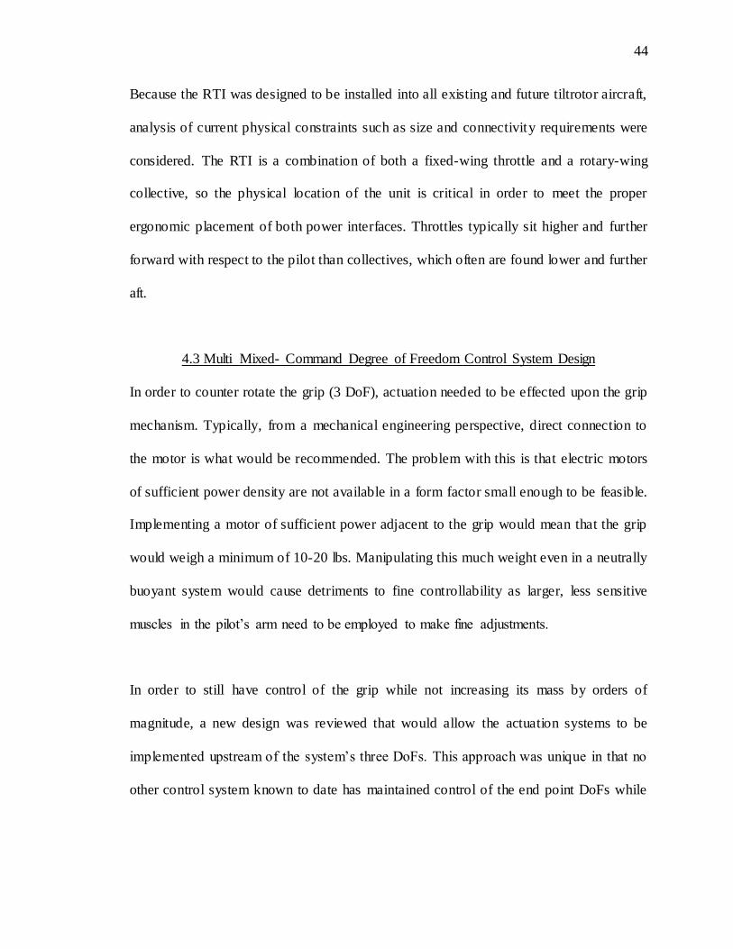
find a mechanism that reduced both mechanical complexity and weight. The system
weight target for the RTI was 40 lbs. or less as the current collective system in the AW-
609 is ~80 lbs. Figures 18, 19, 20, and 21 depict the mechanical system.
Figure 18. RTI Lower half of arm housing
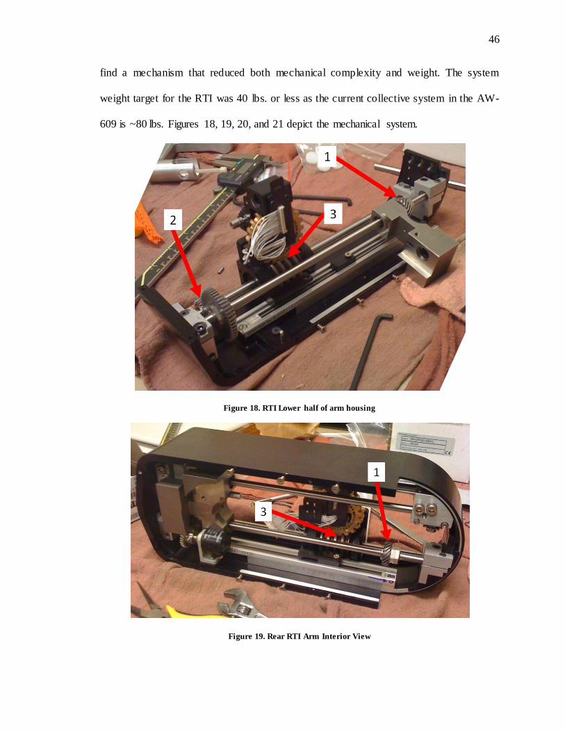
Figure 19. Rear RTI Arm Interior View
47
47
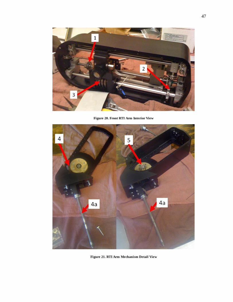
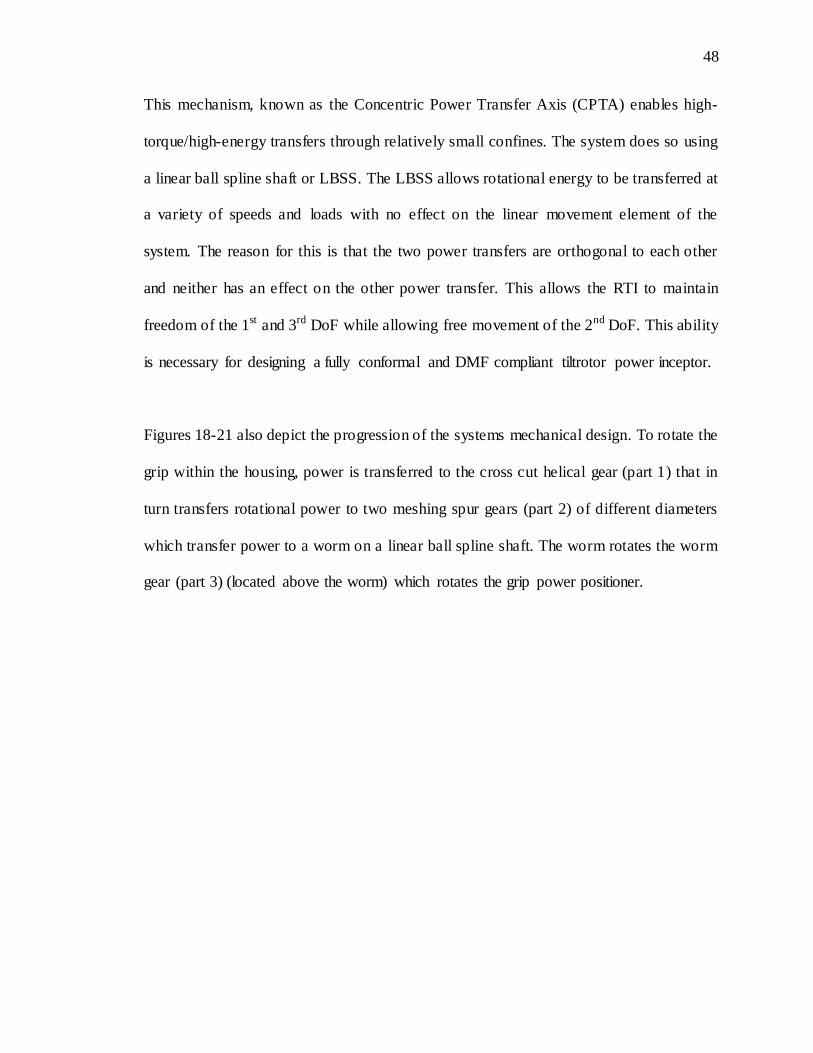
Figure 20. Front RTI Arm Interior View
Figure 21. RTI Arm Mechanism Detail View
48
48
This mechanism, known as the Concentric Power Transfer Axis (CPTA) enables high-
torque/high-energy transfers through relatively small confines. The system does so using
a linear ball spline shaft or LBSS. The LBSS allows rotational energy to be transferred at
a variety of speeds and loads with no effect on the linear movement element of the
system. The reason for this is that the two power transfers are orthogonal to each other
and neither has an effect on the other power transfer. This allows the RTI to maintain
freedom of the 1st and 3rd DoF while allowing free movement of the 2nd DoF. This ability
is necessary for designing a fully conformal and DMF compliant tiltrotor power inceptor.
Figures 18-21 also depict the progression of the systems mechanical design. To rotate the
grip within the housing, power is transferred to the cross cut helical gear (part 1) that in
turn transfers rotational power to two meshing spur gears (part 2) of different diameters
which transfer power to a worm on a linear ball spline shaft. The worm rotates the worm
gear (part 3) (located above the worm) which rotates the grip power positioner.
49
49
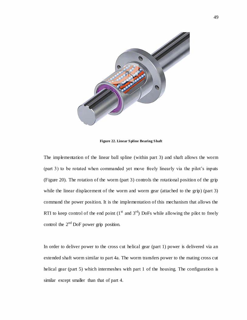
Figure 22. Linear Spline Bearing Shaft
The implementation of the linear ball spline (within part 3) and shaft allows the worm
(part 3) to be rotated when commanded yet move freely linearly via the pilot’s inputs
(Figure 20). The rotation of the worm (part 3) controls the rotational position of the grip
while the linear displacement of the worm and worm gear (attached to the grip) (part 3)
command the power position. It is the implementation of this mechanism that allows the
RTI to keep control of the end point (1st and 3rd) DoFs while allowing the pilot to freely
control the 2nd DoF power grip position.
In order to deliver power to the cross cut helical gear (part 1) power is delivered via an
extended shaft worm similar to part 4a. The worm transfers power to the mating cross cut
helical gear (part 5) which intermeshes with part 1 of the housing. The configuration is
similar except smaller than that of part 4.
50
50
The key importance to the design is transferring power concentrically through the
actuation axes in order to not apply force to other areas. By passing rotational power
through the center of existing rotations, that power can then be routed out downstream
and used to control components of interest. In the case of the power grip (3rd DoF), a
tremendous amount of actuation power was made available by placing a larger motor
upstream of the grip through the described mechanism.
Another novel feature that was implemented was a pilot lockout that impeded the pilot
form back-driving the system. To enable this, worm gear mechanisms are used. The
benefit of a worm gear is that you get tremendous torque advantage due to the natural
reduction the screw provides in addition to the inability to back-drive the system from the
other side of the actuation end. As flight controls need to represent their action and
movement very precisely, it would be detrimental for such a system if it moved without
imparting effect on the control system. As stated before, the rail housing and power grip
are controlled by the system and commanded by the pilot through a discrete switch (as
per spec on the V-22 and AW-609). Since both the rail housing and power grip have such
a long moment arm, it would be very easy for the pilot to move the system uncommanded
by placing force on the unit. This concern is eliminated with the insertion of the worm
gear as the applied force is transferred to the static structure and not the actuation system.

51
51
4.4 Overall Structural Design
With all projects, there are driving factors that influence the design. In the case of the RTI,
there were the six key requirements listed above but in addition, the unit needed to fit
within the aircraft, both physically and aesthetically.
To address weight, cost, esthetics, and structure, aircraft grade aluminum of different
types was used in the RTI’s construction. Aluminum affords a variety of benefits for
rapid prototyping:
1. It is easy to machine
2. Does not corrode readily
3. Can be anodized
Because COTS components were used, both the motors and the motor controllers were
relatively large compared to the RTI as a whole. Due to this, we decided to separate the
RTI electromechanical components from the electrical system and join them though an
electric umbilical cord. The base housing structure was a six-sided structure that used an
internal aluminum sub-frame skeleton for support (Figures 23, 24, and 25).
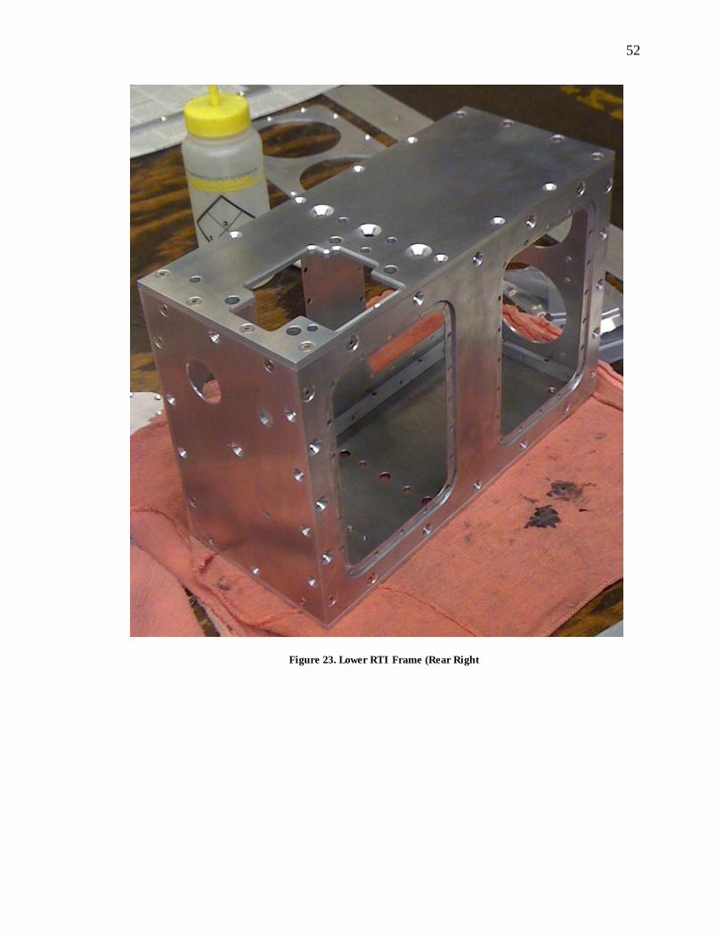
52
52
Figure 23. Lower RTI Frame (Rear Right
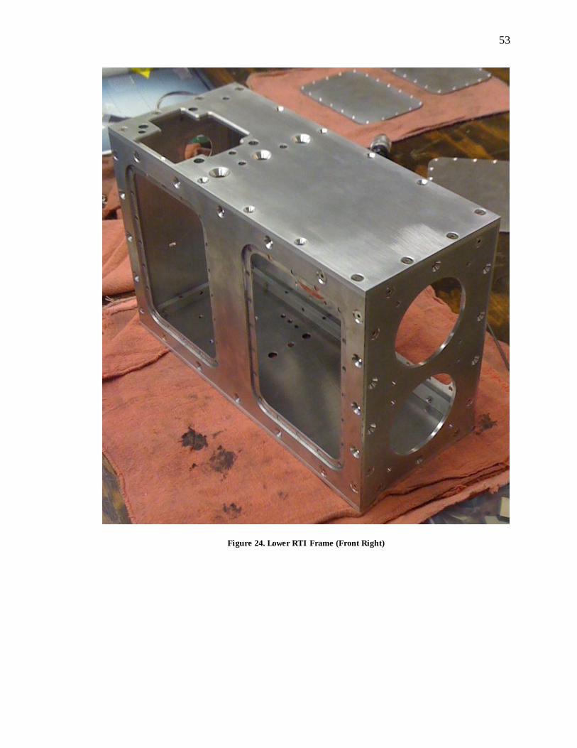
53
53
Figure 24. Lower RTI Frame (Front Right)
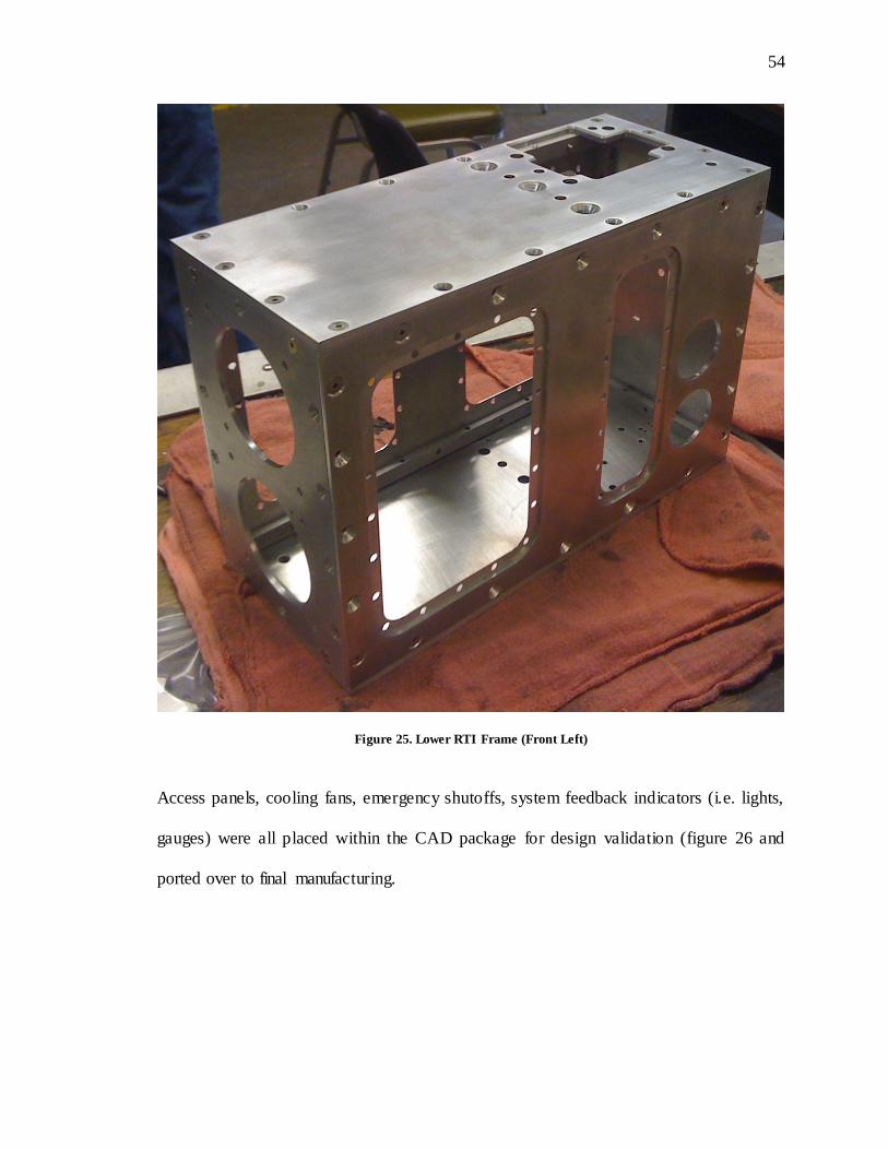
54
54
Figure 25. Lower RTI Frame (Front Left)
Access panels, cooling fans, emergency shutoffs, system feedback indicators (i.e. lights,
gauges) were all placed within the CAD package for design validation (figure 26 and
ported over to final manufacturing.
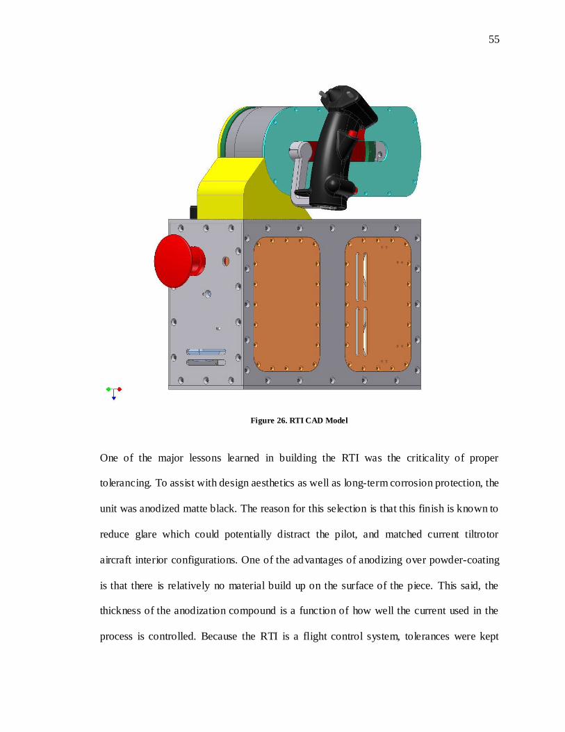
55
55
Figure 26. RTI CAD Model
One of the major lessons learned in building the RTI was the criticality of proper
tolerancing. To assist with design aesthetics as well as long-term corrosion protection, the
unit was anodized matte black. The reason for this selection is that this finish is known to
reduce glare which could potentially distract the pilot, and matched current tiltrotor
aircraft interior configurations. One of the advantages of anodizing over powder-coating
is that there is relatively no material build up on the surface of the piece. This said, the
thickness of the anodization compound is a function of how well the current used in the
process is controlled. Because the RTI is a flight control system, tolerances were kept

56
56
very tight (typically -0”/+0.0005”) in order to eliminate mechanical slop or hysteresis.
Machining tolerances took into account the milling and cutting, however the anodization
was not accounted for, as the process, if done properly, does not leave any material build
up. Unfortunately, this was not what occurred in the case of the RTI. It appears, after post
analysis, that the current was not held constant and exceeded the recommended
specification. This was determined by the fact that the thickness of the anodization well
exceeded any current norm. To compound matters further, critical fit parts were not
masked off due to time constraints allowing the anodizing material to infiltrate high
precision areas.
Fitting of the unit went relatively smoothly as the CAD model was used to do virtual
builds prior to final manufacturing and assembly. Figures 27, 28, 29, and 30 depict a
composite assembly sequence of the RTI build progression.

57
57
Figure 27. Lower RTI Section
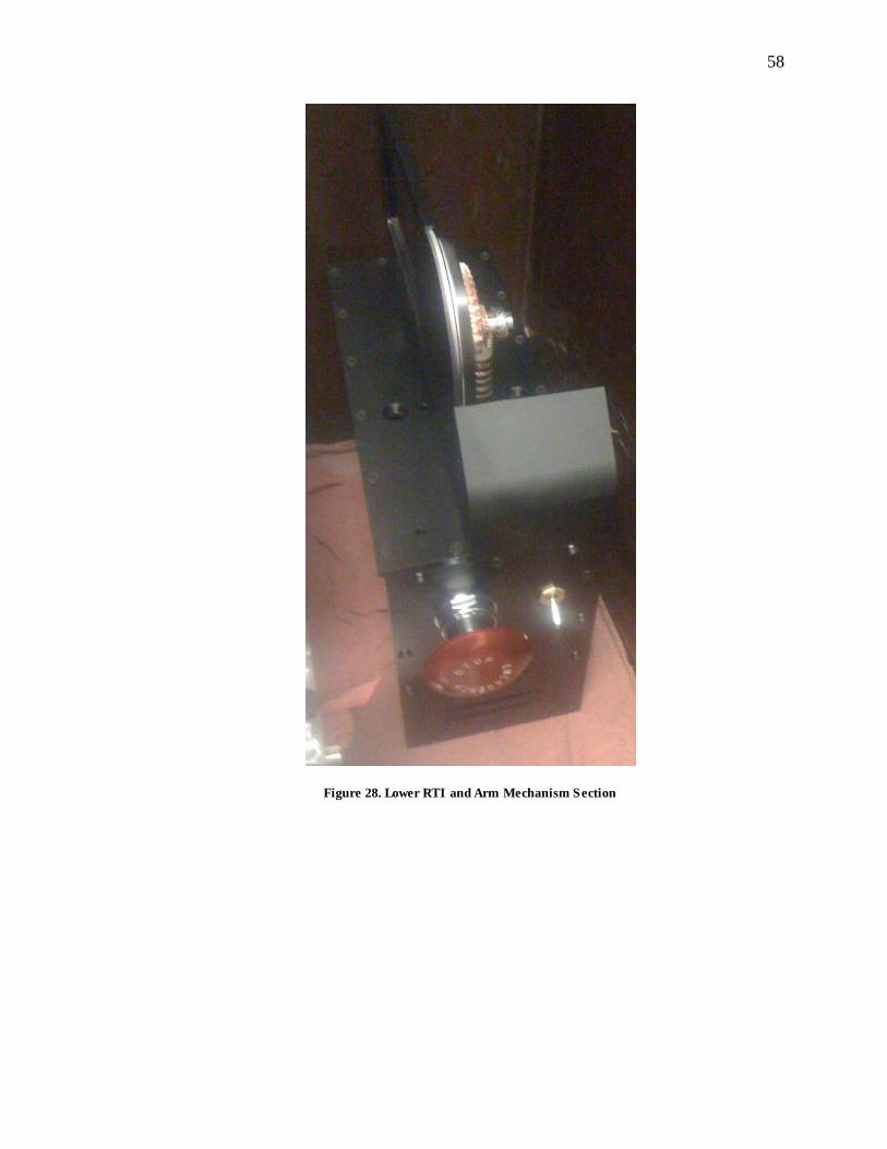
58
58
Figure 28. Lower RTI and Arm Mechanism Section

59
59
Figure 29. Open RTI Mechanical Section
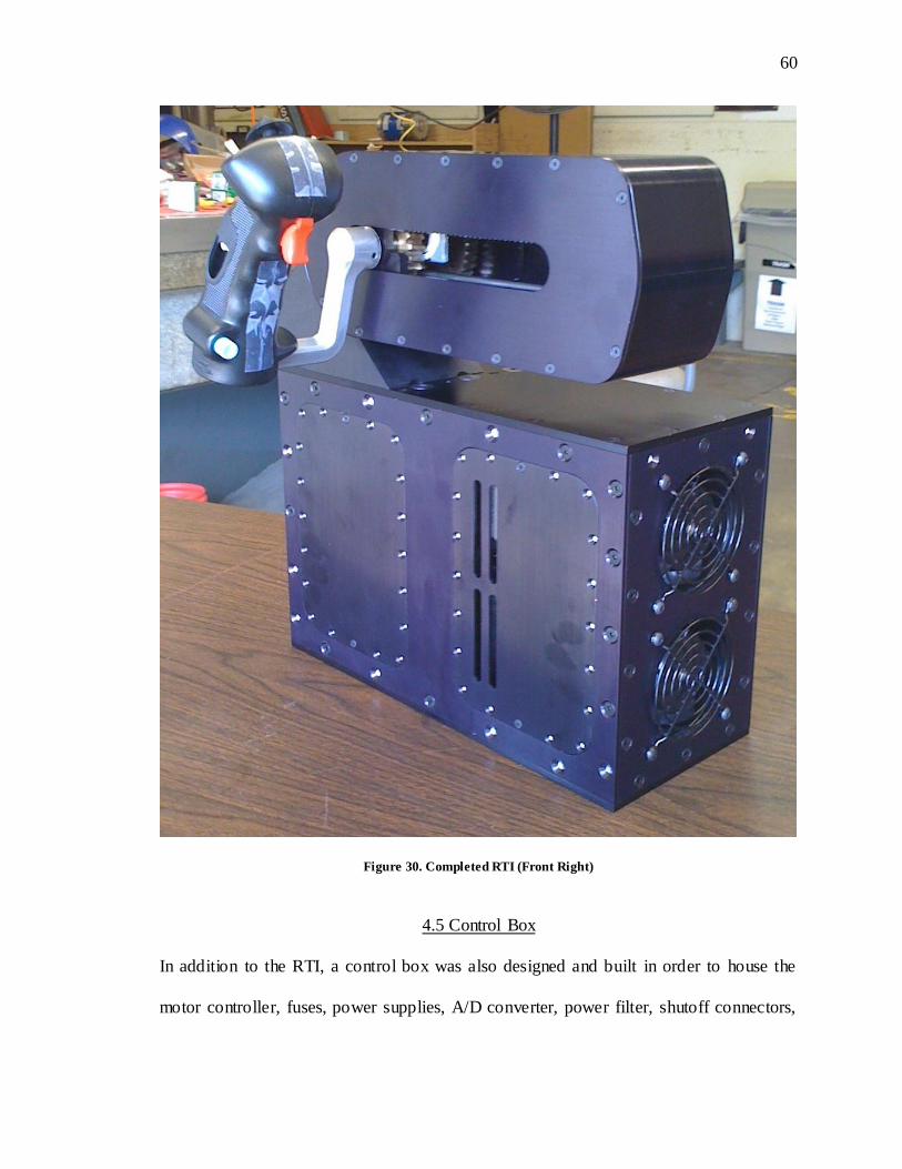
60
60
Figure 30. Completed RTI (Front Right)
4.5 Control Box
In addition to the RTI, a control box was also designed and built in order to house the
motor controller, fuses, power supplies, A/D converter, power filter, shutoff connectors,
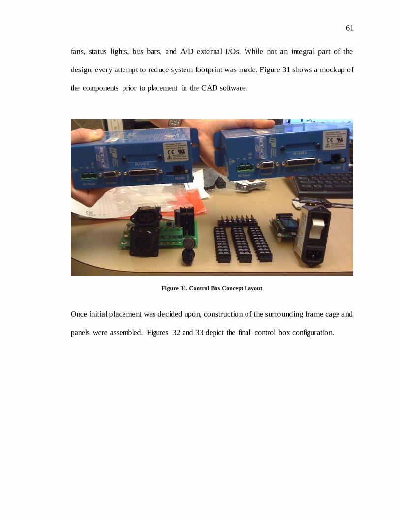
61
61
fans, status lights, bus bars, and A/D external I/Os. While not an integral part of the
design, every attempt to reduce system footprint was made. Figure 31 shows a mockup of
the components prior to placement in the CAD software.
Figure 31. Control Box Concept Layout
Once initial placement was decided upon, construction of the surrounding frame cage and
panels were assembled. Figures 32 and 33 depict the final control box configuration.
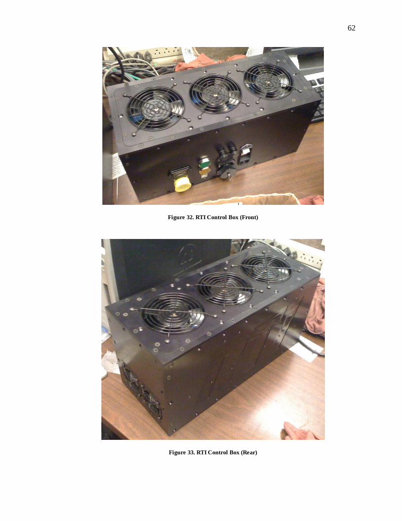
62
62
Figure 32. RTI Control Box (Front)
Figure 33. RTI Control Box (Rear)

63
63
Construction of the fully functional RTI prototype was completed in the summer of 2010,
The final prototype took approximately 18 months to manufacture and assemble and
consisted of more than 350 components. The prototype unit demonstrated a 18% weight
savings with an estimated 50% weight savings in final production over the current BA-
609 collective system (D. King, personal communication, July 10, 2007).
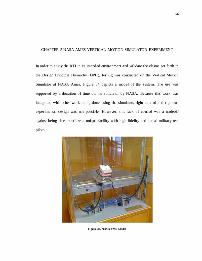
64
64
CHAPTER 5 NASA AMES VERTICAL MOTION SIMULATOR EXPERIMENT
In order to study the RTI in its intended environment and validate the claims set forth in
the Design Principle Hierarchy (DPH), testing was conducted on the Vertical Motion
Simulator at NASA Ames, Figure 34 depicts a model of the system. The use was
supported by a donation of time on the simulator by NASA. Because this work was
integrated with other work being done using the simulator, tight control and rigorous
experimental design was not possible. However, this lack of control was a tradeoff
against being able to utilize a unique facility with high fidelity and actual military test
pilots.
Figure 34. NASA VMS Model
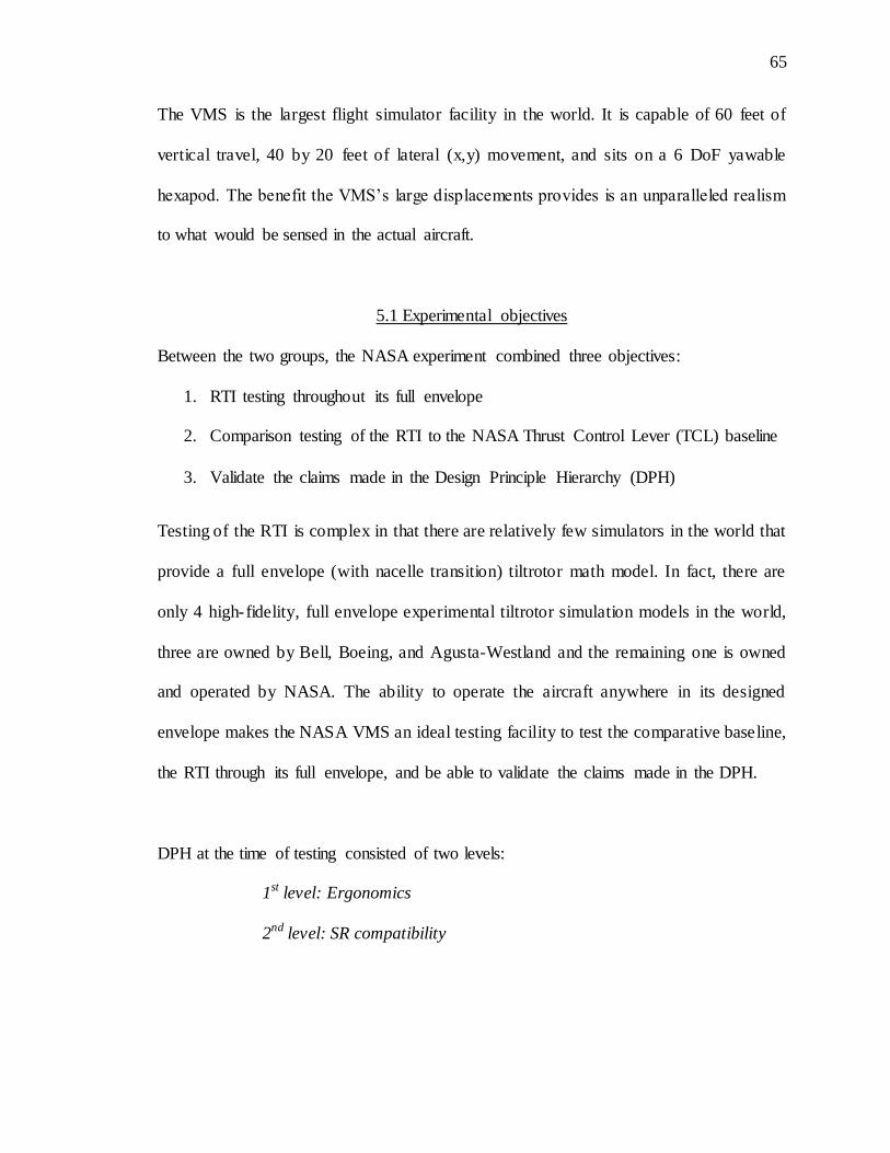
65
65
The VMS is the largest flight simulator facility in the world. It is capable of 60 feet of
vertical travel, 40 by 20 feet of lateral (x,y) movement, and sits on a 6 DoF yawable
hexapod. The benefit the VMS’s large displacements provides is an unparalleled realism
to what would be sensed in the actual aircraft.
5.1 Experimental objectives
Between the two groups, the NASA experiment combined three objectives:
1. RTI testing throughout its full envelope
2. Comparison testing of the RTI to the NASA Thrust Control Lever (TCL) baseline
3. Validate the claims made in the Design Principle Hierarchy (DPH)
Testing of the RTI is complex in that there are relatively few simulators in the world that
provide a full envelope (with nacelle transition) tiltrotor math model. In fact, there are
only 4 high-fidelity, full envelope experimental tiltrotor simulation models in the world,
three are owned by Bell, Boeing, and Agusta-Westland and the remaining one is owned
and operated by NASA. The ability to operate the aircraft anywhere in its designed
envelope makes the NASA VMS an ideal testing facility to test the comparative baseline,
the RTI through its full envelope, and be able to validate the claims made in the DPH.
DPH at the time of testing consisted of two levels:
1st level: Ergonomics
2nd level: SR compatibility
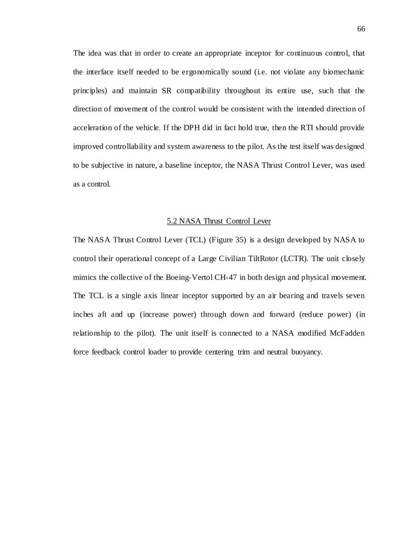
66
66
The idea was that in order to create an appropriate inceptor for continuous control, that
the interface itself needed to be ergonomically sound (i.e. not violate any biomechanic
principles) and maintain SR compatibility throughout its entire use, such that the
direction of movement of the control would be consistent with the intended direction of
acceleration of the vehicle. If the DPH did in fact hold true, then the RTI should provide
improved controllability and system awareness to the pilot. As the test itself was designed
to be subjective in nature, a baseline inceptor, the NASA Thrust Control Lever, was used
as a control.
5.2 NASA Thrust Control Lever
The NASA Thrust Control Lever (TCL) (Figure 35) is a design developed by NASA to
control their operational concept of a Large Civilian TiltRotor (LCTR). The unit closely
mimics the collective of the Boeing-Vertol CH-47 in both design and physical movement.
The TCL is a single axis linear inceptor supported by an air bearing and travels seven
inches aft and up (increase power) through down and forward (reduce power) (in
relationship to the pilot). The unit itself is connected to a NASA modified McFadden
force feedback control loader to provide centering trim and neutral buoyancy.

67
67
Figure 35. NASA VMS TCL
5.3 RTI/VMS Compatibility
Connectivity between the RTI and VMS had to be accomplished. As stated in item four
of the initial six RTI design requirements, I wanted to have the ability to interface to
future and existing flight simulators. In order to do this, I decided that the RTI would be
able to be driven either digitally or analog depending on our requirements. When NASA
offered to provide simulation time on the Vertical Motion Simulator (VMS), the first step
was to gain a better understanding of the Interface Control Document (ICD). The ICD is
the defining communication protocol between the external world and the machine for
which it is written. In the case of the VMS, the system, which was built in 1980, uses
FORTRAN programming language to run the system and the I/Os to the system are
predominantly analog.
Because having the capability to accommodate for analog or digital was deemed an initial
requirement, enabling the RTI to interface to the VMS was more a matter of the physical

68
68
connection than a modification to the interior components or design of the system. To
interface the VMS, the RTI had to have the following I/Os:
1. Nacelle Angle; Input
2. Grip Rotation Angle; Input
3. Throttle Placement: Output
4. Discrete Nacelle Angle Command Switch; Output
5. Continuous Nacelle Angle Command Switch; Output
6. Arm Angle Limit Switches; Internal I/O
7. Internal Emergency Stop; Internal I/O
8. External Emergency Stop; Internal I/O
The nacelle angle input (item 1) provided the angle of the nacelles from the VMS tiltrotor
model to the RTI. This was accomplished through a 0-5 volt analog signal. The signal
itself was closed looped through a single-full-turn rotary potentiometer that provided a 0-
5 volt signal back to verify its position. Calibration of the unit was accomplished through
an engraved protractor on the back of the RTI unit prior to beginning the experimental
trials.
The grip rotation input (item 2) was provided through a linearly interpolated formula
. “m” is the factor modifier for the grip position and
allows the grip angle to be a function of the arm angle. “b” is the offset modifier and sets
the grips initial position. Using “m” or “b”, the grip can be set to any number of positions
and then be driven as a function of the arm angle.

69
69
Throttle placement position was fed out through a linear 150mm potentiometer running
on 0-5 volts. Calibration was done using the end-points of the throttle travel. The RTI has
the ability to produce 5 volts, though, in order to minimize noise and interference, all
signal current was fed in through the VMS and then back out again after being modified
by the sensing potentiometer.
In order to both drive the model’s nacelle angle and have a comparative baseline to
NASA’s TCL, modifications were made to the RTI’s grip (Figure 36) in-house to
accommodate separate discrete and continuous nacelle control switches. The discrete
switch is a spring to center bi-directional 0-5 volt switch. Movement of the discrete
switch commanded a nominal rate of 2.5 degrees per second nacelle transition. The
continuous switch was an Otto stadium style 4-way hat 0-5 volt switch. Even though the
switch was able to move across 2-axes, only the single longitudinal axis was
implemented in the RTI. Movement of the switch commanded a 0-7.5 degrees per second
nacelle transition rate.

70
70
Figure 36. RTI Grip
71
71
During the integration of the RTI into the VMS, an unanticipated failure mode was noted.
In driving the RTI, the VMS system computer would send a start and stop signal to
control the grip angle. The stop was triggered by the position potentiometer’s feedback.
However, if the computer crashed after the start signal was given then sensing of the
position potentiometer would cease and no stop signal could be given. As stated before,
the torque ratings associated with the motors is significantly high. If the RTI hit its
mechanical stops, then it could destroy itself. In order to mitigate this potentially
catastrophic failure mode, limit switches were implemented to control the rail housing’s
position. The limit switches however were connected to the stepper motor position and
speed controller via a normally closed signal. Two independent switches were employed,
one for clockwise (CW) rotation and one for counterclockwise (CCW) rotation. By
implementing the switches in this manner, it could disable driving the system in one
direction to occur but allowed the system to back itself out if needed. In addition, using a
normally closed signal, if the limit switches were disconnected form the system, then the
unit would also shut down. This was advantageous, as in a normally open system, a
disconnect would not register as there would be no system state change.
The last portion of the I/O series was the internal and external emergency stops. Again, as
the motors were capable of tearing the unit apart, safety considerations for the pilot and
system observer needed to be implemented. Two separate emergency shutoffs were
provided. Each one was normally closed and a trip or disconnect between the system and
switch would command a full power-down.
72
72
During RTI assembly, I requested an example of the connector plug that would be used
for the VMS trials. This was done so that the plug could be incorporated physically into
the system, reducing the amount of effort needed to connect the RTI to the VMS. In order
to switch between the digital/analog system, the engineer would simply remove a plug
from the Digital I/O board, bypassing all signals to a pure analog format.
5.4 VMS Bench Testing and Connectivity Verification
While provisions were made to mitigate the connectivity impact of the RTI to the VMS,
calibration and testing needed to occur. As the VMS is a heavily utilized and expensive
resource, projects typically do not have the luxury of validation testing on the motion
beam prior to the experiment. In order to accomplish this task, testing needed to occur on
a test bench. Figure 37 depicts the bench test configuration.
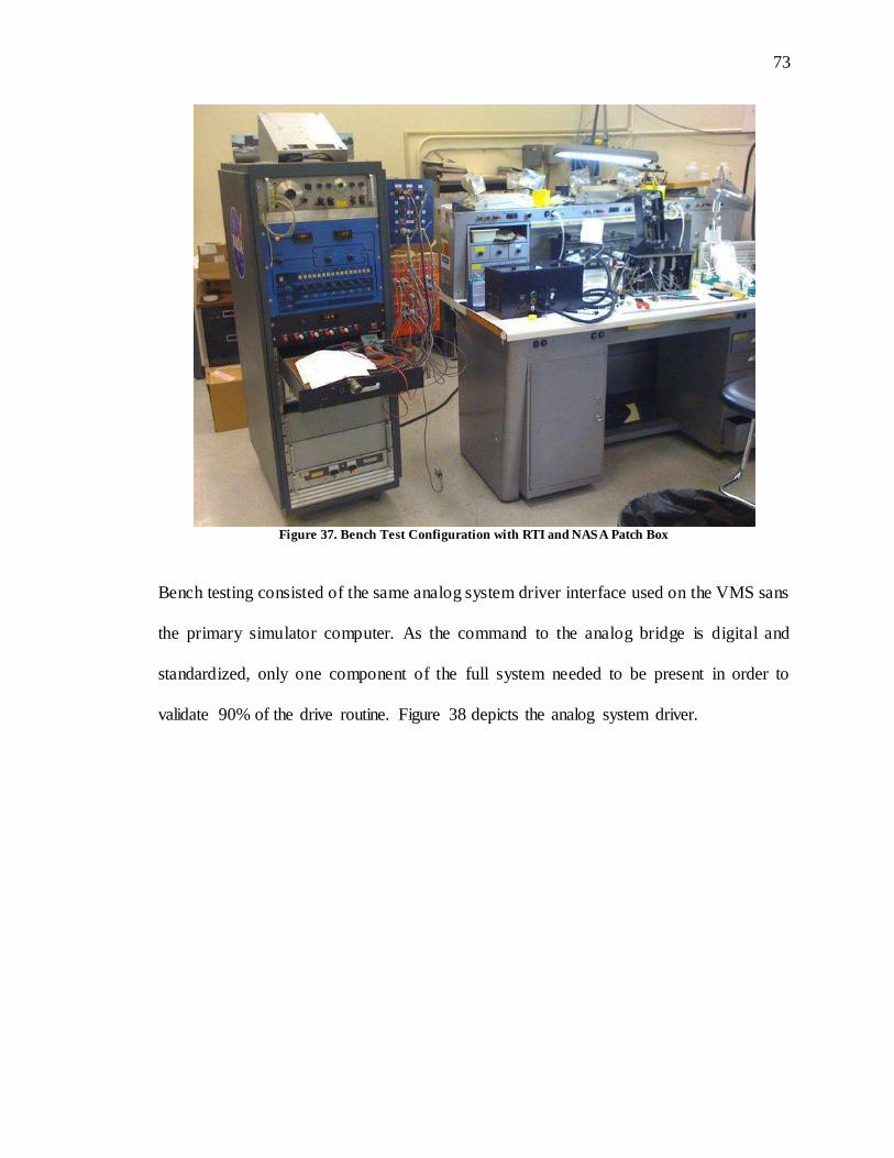
73
73
Figure 37. Bench Test Configuration with RTI and NASA Patch Box
Bench testing consisted of the same analog system driver interface used on the VMS sans
the primary simulator computer. As the command to the analog bridge is digital and
standardized, only one component of the full system needed to be present in order to
validate 90% of the drive routine. Figure 38 depicts the analog system driver.

74
74
Figure 38. NASA VMS A to D Converter Patch Box
The orange and blue patch panel on the right side of the unit are designed to be
configured and moved with the system to the VMS to minimize configuration changes
across system platforms. From the VMS system perspective, the RTI appeared just like
any of the other flight controls the system utilized once coding was complete.
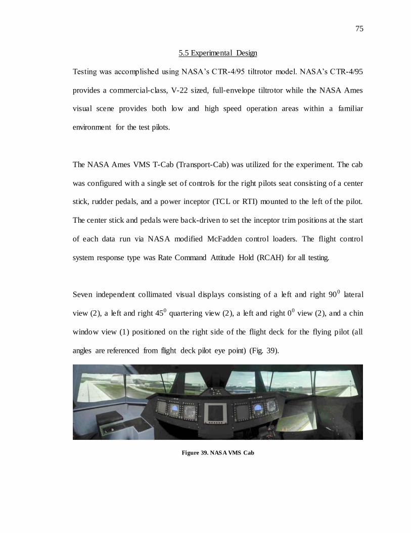
75
75
5.5 Experimental Design
Testing was accomplished using NASA’s CTR-4/95 tiltrotor model. NASA’s CTR-4/95
provides a commercial-class, V-22 sized, full-envelope tiltrotor while the NASA Ames
visual scene provides both low and high speed operation areas within a familiar
environment for the test pilots.
The NASA Ames VMS T-Cab (Transport-Cab) was utilized for the experiment. The cab
was configured with a single set of controls for the right pilots seat consisting of a center
stick, rudder pedals, and a power inceptor (TCL or RTI) mounted to the left of the pilot.
The center stick and pedals were back-driven to set the inceptor trim positions at the start
of each data run via NASA modified McFadden control loaders. The flight control
system response type was Rate Command Attitude Hold (RCAH) for all testing.
Seven independent collimated visual displays consisting of a left and right 900 lateral
view (2), a left and right 450 quartering view (2), a left and right 00 view (2), and a chin
window view (1) positioned on the right side of the flight deck for the flying pilot (all
angles are referenced from flight deck pilot eye point) (Fig. 39).
Figure 39. NASA VMS Cab
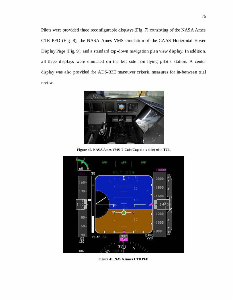
76
76
Pilots were provided three reconfigurable displays (Fig. 7) consisting of the NASA Ames
CTR PFD (Fig. 8), the NASA Ames VMS emulation of the CAAS Horizontal Hover
Display Page (Fig. 9), and a standard top-down navigation plan view display. In addition,
all three displays were emulated on the left side non-flying pilot’s station. A center
display was also provided for ADS-33E maneuver criteria measures for in-between trial
review.
Figure 40. NASA Ames VMS T-Cab (Captain’s side) with TCL
Figure 41. NASA Ames CTR PFD
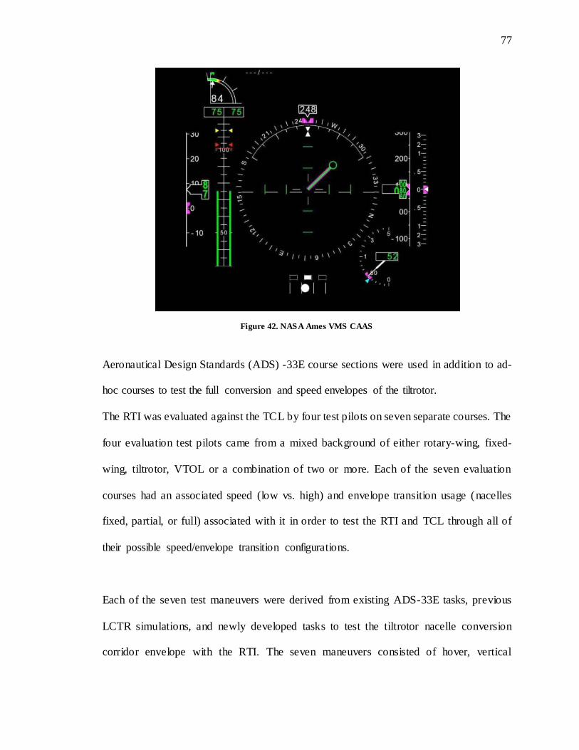
77
77
Figure 42. NASA Ames VMS CAAS
Aeronautical Design Standards (ADS) -33E course sections were used in addition to ad-
hoc courses to test the full conversion and speed envelopes of the tiltrotor.
The RTI was evaluated against the TCL by four test pilots on seven separate courses. The
four evaluation test pilots came from a mixed background of either rotary-wing, fixed-
wing, tiltrotor, VTOL or a combination of two or more. Each of the seven evaluation
courses had an associated speed (low vs. high) and envelope transition usage (nacelles
fixed, partial, or full) associated with it in order to test the RTI and TCL through all of
their possible speed/envelope transition configurations.
Each of the seven test maneuvers were derived from existing ADS-33E tasks, previous
LCTR simulations, and newly developed tasks to test the tiltrotor nacelle conversion
corridor envelope with the RTI. The seven maneuvers consisted of hover, vertical
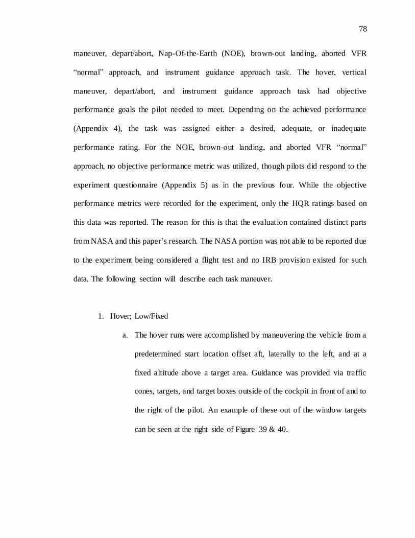
78
78
maneuver, depart/abort, Nap-Of-the-Earth (NOE), brown-out landing, aborted VFR
“normal” approach, and instrument guidance approach task. The hover, vertical
maneuver, depart/abort, and instrument guidance approach task had objective
performance goals the pilot needed to meet. Depending on the achieved performance
(Appendix 4), the task was assigned either a desired, adequate, or inadequate
performance rating. For the NOE, brown-out landing, and aborted VFR “normal”
approach, no objective performance metric was utilized, though pilots did respond to the
experiment questionnaire (Appendix 5) as in the previous four. While the objective
performance metrics were recorded for the experiment, only the HQR ratings based on
this data was reported. The reason for this is that the evaluation contained distinct parts
from NASA and this paper’s research. The NASA portion was not able to be reported due
to the experiment being considered a flight test and no IRB provision existed for such
data. The following section will describe each task maneuver.
1. Hover; Low/Fixed
a. The hover runs were accomplished by maneuvering the vehicle from a
predetermined start location offset aft, laterally to the left, and at a
fixed altitude above a target area. Guidance was provided via traffic
cones, targets, and target boxes outside of the cockpit in front of and to
the right of the pilot. An example of these out of the window targets
can be seen at the right side of Figure 39 & 40.
79
79
2. Vertical Maneuver; Low/Fixed
a. The vertical maneuver was accomplished by executing a vertical climb,
arresting at a specified altitude, and then a descent to the start position
within a specified time while maintaining heading, longitudinal, and
lateral position within specified desired and adequate limits. Guidance
again was provided via simulated traffic cones, targets, and target
boxes oriented in front of and laterally to the right of the pilot.
3. Depart/Abort Maneuver; Low/Partial
a. The depart/abort maneuver began with the aircraft in a hover at a
predetermined fixed location. Using the nacelle rotation, the pilot
accelerated to 40 knots. At 40 knots, using nacelle control, the pilot
decelerated to stop at a hover within a predetermined area. The time to
complete the maneuver, stopping position, and vehicle attitude were
used as performance measures/metrics.
4. Nap-Of-the-Earth; High/Partial
a. Performance of the inceptors in low level flight was evaluated using a
simulated Nap-Of-the-Earth (NOE) task through the NASA Ames
campus. Speed was controlled via nacelle rotation and throttle position.
Speeds ranged from 0 to 85 knots. Figure 11 depicts the simulated
NOE course.
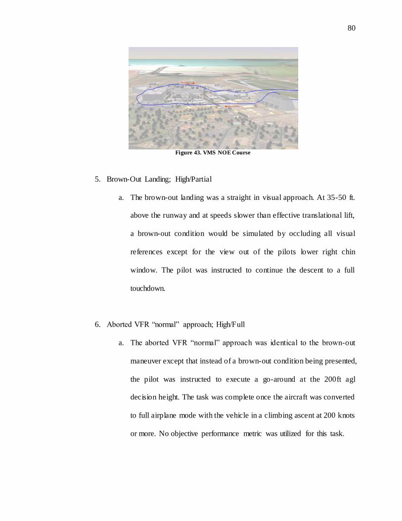
80
80
Figure 43. VMS NOE Course
5. Brown-Out Landing; High/Partial
a. The brown-out landing was a straight in visual approach. At 35-50 ft.
above the runway and at speeds slower than effective translational lift,
a brown-out condition would be simulated by occluding all visual
references except for the view out of the pilots lower right chin
window. The pilot was instructed to continue the descent to a full
touchdown.
6. Aborted VFR “normal” approach; High/Full
a. The aborted VFR “normal” approach was identical to the brown-out
maneuver except that instead of a brown-out condition being presented,
the pilot was instructed to execute a go-around at the 200ft agl
decision height. The task was complete once the aircraft was converted
to full airplane mode with the vehicle in a climbing ascent at 200 knots
or more. No objective performance metric was utilized for this task.

81
81
7. Instrument Guidance Approach; High/Full
a. The instrument guidance approach task was the longest of the seven
maneuvers and was a full visual approach to land with the pilot
beginning on a 450 entry to left downwind for Moffett field. The pilot
was required to convert the aircraft from airplane to helicopter mode
and execute a landing at the runway number markings. No objective
performance metric was utilized for this task.
Pilots flew each course a minimum of three times for practice followed by one trial data
run. At the completion of the run pilots were asked to provide comments based off of an
18 item questionnaire (Appendix 5) and assign a Handling Quality Ratings (HQR) score
to the task. The HQR Scale was developed by Cooper and Harper after World War II and
was designed to provide ratings on the systems being evaluated. The scale, as depicted in
figure 44, is designed to be used only by formally trained test pilots and is broken down
into 4 levels.
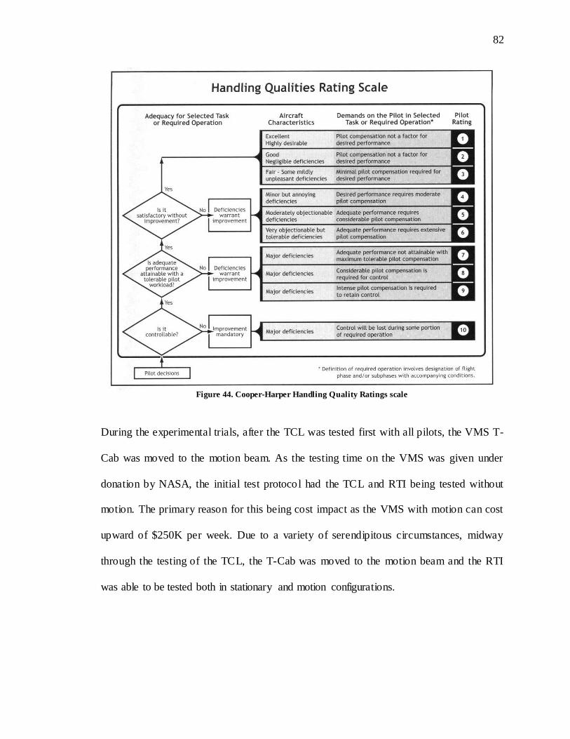
82
82
Figure 44. Cooper-Harper Handling Quality Ratings scale
During the experimental trials, after the TCL was tested first with all pilots, the VMS T-
Cab was moved to the motion beam. As the testing time on the VMS was given under
donation by NASA, the initial test protocol had the TCL and RTI being tested without
motion. The primary reason for this being cost impact as the VMS with motion can cost
upward of $250K per week. Due to a variety of serendipitous circumstances, midway
through the testing of the TCL, the T-Cab was moved to the motion beam and the RTI
was able to be tested both in stationary and motion configurations.
83
83
5.6 Results
From a flight perspective, control was possible throughout helicopter, fixed-wing, and
transition modes with both the baseline TCL and experimental RTI. However some data
illustrated some deficiencies with the RTI that were reflected in the pilot’s comments and
HQRs. Pilots reported three predominant concerns with the thrust control operating the
RTI:
1. The rotation of the RTI with nacelle angle during transition created some
confusion in which way to move the grip to control the throttle.
2. Pilots were not able to distinguish between fine changes in the RTI’s housing
angle making interpretation of exact nacelle position angle difficult. While this
did not have an effect on overall task performance, it was an unexpected finding.
3. Precise throttle control with the RTI was difficult due to an unanticipated binding
of the system along the throttle axis.
These concerns are discussed further in the following sections.
5.7 HQR Results
There were some initial issues with the data collection routine that did not allow for full
collection of all HQR data points. The data presented below is the same data presented at
the 67th American Helicopter Society forum at Virginia Beach (Rozovski & Theodore,
2011). Presentation at this conference was a requirement by NASA in order to use the
VMS.
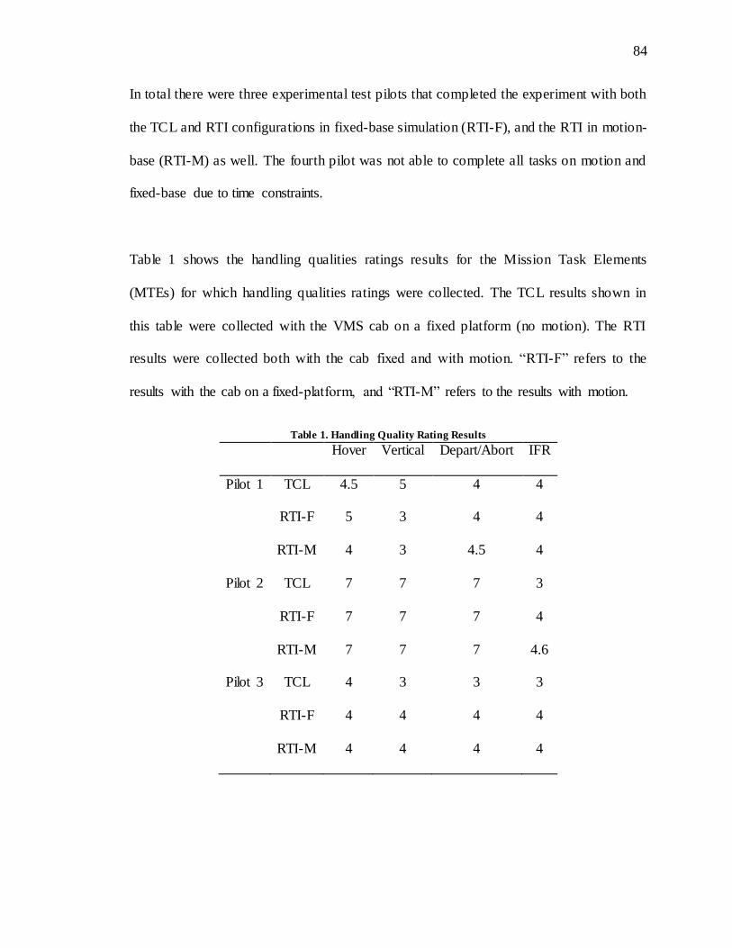
84
84
In total there were three experimental test pilots that completed the experiment with both
the TCL and RTI configurations in fixed-base simulation (RTI-F), and the RTI in motion-
base (RTI-M) as well. The fourth pilot was not able to complete all tasks on motion and
fixed-base due to time constraints.
Table 1 shows the handling qualities ratings results for the Mission Task Elements
(MTEs) for which handling qualities ratings were collected. The TCL results shown in
this table were collected with the VMS cab on a fixed platform (no motion). The RTI
results were collected both with the cab fixed and with motion. “RTI-F” refers to the
results with the cab on a fixed-platform, and “RTI-M” refers to the results with motion.
Table 1. Handling Quality Rating Results
Hover Vertical Depart/Abort IFR
Pilot 1 TCL 4.5 5 4 4
RTI-F 5 3 4 4
RTI-M 4 3 4.5 4
Pilot 2 TCL 7 7 7 3
RTI-F 7 7 7 4
RTI-M 7 7 7 4.6
Pilot 3 TCL 4 3 3 3
RTI-F 4 4 4 4
RTI-M 4 4 4 4
85
85
Pilot 2 was a fixed wing pilot with Harrier experience and was not accustomed to
helicopter flight and collective control systems for hover and low speed tasks,
specifically the rate command attitude hold. The HQ ratings of 7 could therefore be
explained by the pilots training and inexperience with helicopters.
The hover and vertical maneuver task results shown in table 1 did not require any nacelle
angle change and therefore did not include any effects of RTI transition. The results for
these two tasks show a slight degradation in the handling qualities ratings with the RTI
when compared with the TCL. This degradation is also reflected in the pilot comments to
the questions listed in the appendix. The differences in ratings were not a result of RTI
transition as it did not rotate during the hover and vertical maneuvers. The differences
however can be explained by the following:
1. The physical positioning of the RTI is a compromise between a collective and
throttle due to its combination of the two and its transformation via rotation. Pilots
commented that the RTI did not feel as natural as a standard collective, throttle, or
TCL which is also a collective effectively. The reasoning for this is that the linear
displacement of the RTI in either collective or throttle mode does not and cannot
replicate a collective or throttle.
2. All pilots noted some binding or stiction of the RTI’s throttle travel making it
difficult to precisely set and adjust the throttle grip position. Pilots were asked to
comment on the binding, but to try to limit its effects on the handling qualities
ratings. It is still suspected that some of the degradation in HQ ratings with the
86
86
RTI is still due to the binding. The reason for the binding was due to a
manufacturing error. The RTI’s throttle is a sled that moves along two parallel
bars. Due to anodization issues, the travel bars had a center distance that was
shorter than the center distance of the receiving race on the throttle sled assembly.
Due to this mismatch, binding would occur at the extreme points of the throttle
travel due to a wedging effect. The RTI’s throttle, however, experienced little to
no binding in the center ranges as the bars were able to flex to the appropriate
center distances set by the throttle sled assembly.
Binding or high breakout forces can have severe effects on precision control,
requiring very high initial force with low continual force after, something that is
very hard to modulate if not properly supported. This is believed to have
contributed to the degradation in the associated HQRs.
3. A third possible reason was that the orientation of the grip and amount of travel
available between the TCL and RTI grip were different. The TCL motion axis is
also angled slightly aft of vertical, while the RTI motion axis is slightly forward
to match the nacelle trim pitch attitude of 86 degrees for this aircraft on vertical
takeoff as to ensure that the mains always touch first during landing and to
mitigate nose wheel loading on takeoff. The RTI’s straight upward vertical throw
was the focus of many comments regarding ergonomics or comfort, which is
believed to have driven the HQRs downward. Based on the RTI design drivers,
this was not a negotiable feature of the system.

87
87
For the depart/abort and instrument guidance approach tasks that involved nacelle angle
changes and corresponding rotation of the RTI, HQ ratings were generally worse with the
RTI than with the TCL. One factor to keep in mind when considering these results is the
influence of the binding or stiction that was seen with the RTI. As previously mentioned,
pilots were asked try to limit the effect of binding on their handling qualities ratings, or
essentially to provide a handling qualities rating for the RTI if binding had not been
present. Even with this instruction, it is still believed that the binding issue accounts for
some of the degradation with the RTI HQRs and is reflected heavily in the comments.
Another important factor in the degradation of the handling qualities ratings with the RTI
is that pilots experienced some confusion as to which direction to move the grip to add
and remove power during nacelle transition as the flight condition and nacelle angle
changed. This will be discussed in more detail later in this section.
In order to more fully assess the effects of the RTI, it is important to consider the pilot
comments in the evaluation. Typically pilot comments provide a much richer set of data
than just the handling qualities ratings alone. With respect to the binding, the
predominant effect was that it was more difficult to make fine power adjustments along
the throttle axis. Subjective pilot comments further indicated that the magnitude of this
effect was tightly coupled to the aggressiveness of the maneuver. One pilot reported in
the brownout maneuver for the 2nd question inquiry, “not an aggressive maneuver but
able to be as aggressive as wanted to be, precision for RTI was fine.” In contrast, in a
similarly aggressive maneuver, another pilot indicated, “just following the guidance,
aggressive to follow the guidance… with RTI tended to put in too big an input which was
88
88
a function of the binding.” Unfortunately, correction of the binding issue was not possib le
during this test, however it was resolved after and is not considered to be a technical
hurdle of the system. While pilots were asked to try to disregard the b inding in the system,
it still affected HQR ratings and comments throughout the entire evaluation.
For the depart/abort and instrument guidance approach tasks, the RTI vibrated slightly
while the inceptor was converting due to a slight misalignment of the internal gear
mechanisms that controlled the rotation. This was not intended, but did give a positive
outcome where the pilots received a haptic indication that the nacelles were actually
moving via the inceptor vibration, this was noted particularly by the pilots who had no
prior tiltrotor flight. The single pilot with tiltrotor experience was more familiar with the
response of other cues in the cockpit (e.g. outside visuals, motion, and cockpit cues) as to
whether the nacelles were moving. For pilots that are unfamiliar with these
vestibular/visual cues, the only indication of nacelle angle and movement is from an
indicator on the PFD; an example of this symbology can be found in the upper left corner
of the displays in figures 41 and 42.
Pilots commented that neither the rotational position of the RTI nor the RTI grip provided
a precise reading of the nacelle position. Pilots were able to distinguish between gross
position changes and major orientations such as vertical or horizontal, however, they
were not able to sense RTI position with greater than ~20 degrees of accuracy.
89
89
Pilots also commented that they often found themselves trying to move the throttle grip in
the wrong direction to increase and decrease thrust against the direction of travel,
particularly during conversion. Pilots commented that they were often trying to push the
grip in the wrong direction. One possible reason for this issue could be attributed by the
method in which rotary-wing pilots manipulate power settings verses fixed-wing pilots.
In a conventional helicopter, the pilot adds power by pulling with their fingertips, while
in an airplane, power is added by the pilot pushing with their palm. Because the RTI
combines both of these inceptors into a single device, the confusion may lie in that
midway through, the proprioceptive aspect of the control strategy reverses.
One pilot commented that it may be better if the pilot was able to manually control the
conversion of the RTI between helicopter and airplane mode rather than having it
automatically tied to the nacelle angle. This way the pilot would be able to control when
the inceptor transitioned from vertical (helicopter) and horizontal (airplane) modes. This
may eliminate the confusion in which way to move the inceptor in the intermediate
(transition) positions.
5.8 Conclusions
Pilots indicated some deficiencies in the RTI partly due to an unintended binding issue
along the throttle axis. Non-linear binding along the throttle axis causes significant
detriment to the pilots ability to accurately set power control. The conclusions gained
from this study were valuable in understanding the critical components of the design,
construction, execution, and testing of the RTI. The main lessons learned were:

90
90
1. Pilots were able to perform all of the tasks with the RTI throughout helicopter,
airplane, and transition flight modes.
2. The 1:1 mapping of the inceptor angle to the nacelle angle did cause some
confusion during nacelle rotation as to which direction to move the RTI grip to
control power.
3. Fine angular sensitivity was not possible in the RTI within better than 20 degrees
resolution.
4. Haptic feedback from the RTI during nacelle rotation provided an additional
beneficial cue of nacelle movement.
5. Physical placement of the RTI was difficult due to a compromise in fixed-wing
throttle and rotary-wing collective positioning differences.
5.9 Major Findings, to the Design Principle Hierarchy
During testing, deficiencies with the RTI were discovered. Two deficiencies in particular
were noted: first, the pilot was unable to distinguish between small angle changes of the
RTI during RTI movement, and second, the pilot suffered control reversals. While
angular sensitivity is understandable, the control reversal occurrence was not anticipated.
The control reversal appears to be driven by a violation of a previously un-described
phenomenon, proprioceptive consistency.
Proprioceptive consistency is defined here as the individual’s use of specific and
consistent haptic cues that guide them through the proper control strategy. For instance,
91
91
in an automobile, with the individual’s hands at the 10 and 2 o’clock position, the control
inputs to make the car turn left or right remain consistent as well as the haptic or
proprioceptive sensation the individual experiences. This is to say, the force and direction
of force a person perceives on their hand during this event is consistent for each
respective action. Violations to this principle may to drive control reversals, as the
individual erroneously relies on the cue in order to execute their control strategy.
This finding suggests that an additional principle is needed within the DPH for proper
inceptor design: Proprioceptive consistency. To accommodate this new principle, one
would have to make the haptic feel the device consistent across the flight envelope.
However, in order to accommodate this principle, the RTI would have to be placed above
and forward of the individual’s lateral axis shoulder point, which would then violate the
first level of design; ergonomics. The new structure of the design theory would appear as
follows:
1st level: Ergonomics
2nd Level: Proprioceptive Consistency
3rd level: SR compatibility
An alternate solution to resolve this issue is to discretize the RTI’s transition envelope
(Figure 45), reducing the amount of time the pilot spends in the portion of flight where
the proprioceptive inconsistency occurs. Specifically, when the tiltrotor is operating in
helicopter mode, the RTI would represent a helicopter collective, and when the tiltrotor is
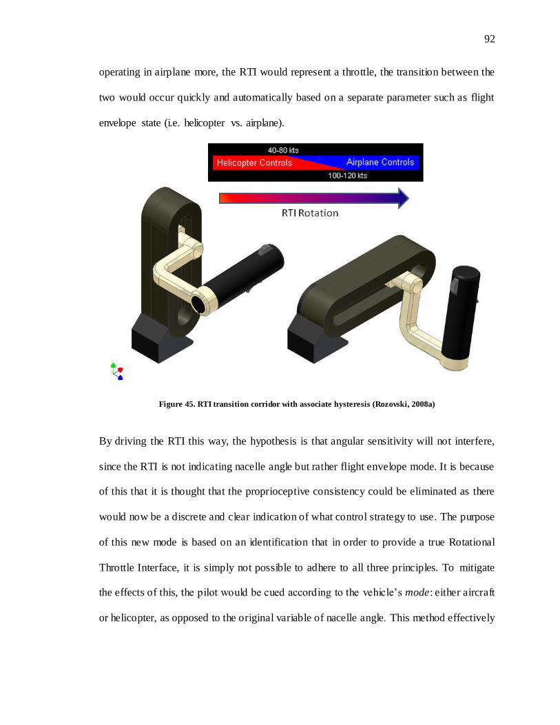
92
92
operating in airplane more, the RTI would represent a throttle, the transition between the
two would occur quickly and automatically based on a separate parameter such as flight
envelope state (i.e. helicopter vs. airplane).
Figure 45. RTI transition corridor with associate hysteresis (Rozovski, 2008a)
By driving the RTI this way, the hypothesis is that angular sensitivity will not interfere,
since the RTI is not indicating nacelle angle but rather flight envelope mode. It is because
of this that it is thought that the proprioceptive consistency could be eliminated as there
would now be a discrete and clear indication of what control strategy to use. The purpose
of this new mode is based on an identification that in order to provide a true Rotational
Throttle Interface, it is simply not possible to adhere to all three principles. To mitigate
the effects of this, the pilot would be cued according to the vehicle’s mode: either aircraft
or helicopter, as opposed to the original variable of nacelle angle. This method effectively

93
93
replicates the design of the XC-142 inceptor configuration, except that there is one
control system, not two, and the pilot does not need to remove his or her hand from the
controller during flight.
94
94
CHAPTER 6 NATIONAL RESEARCH COUNCIL OF CANADA’S FLIGHT RESEARCH LAB SIMULATOR EXPERIMENT
After completion of the flight simulation tests at NASA, the binding was reduced by
approximately 90% by realigning the guide rails. To test the RTI without the majority of
the binding issue, and to evaluate the “two-mode” recommendation from the NASA
evaluation, a second set of flight simulation evaluation were designed and conducted at
the National Research Center of Canada’s Flight Research Laboratory. The experiment
was designed to test the hypothesis of the Proprioceptive Consistency criticality and the
proposed solution of discretization of the RTI control modes (collective vs. throttle) by
reducing the amount of time the pilot spends within the transition mode.
6.1 Experimental Design
The primary question the second follow up experiment was designed to answer was:
1. Does automating the motion of the RTI according to the vehicle’s flight envelope
mitigate or eliminate control confusion? Alternatively does the new mode
possibly increase confusion and control reversals?
Handling Quality Ratings about the inceptor proper were the primary metric used to
evaluate whether the automated transition of the RTI result in superior handling qualities
when compared to the conditions in which the RTI position matches nacelle angle or is
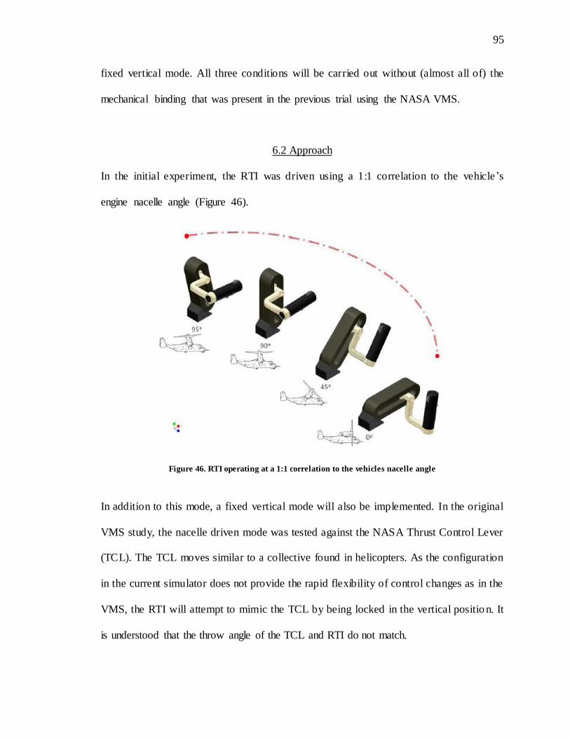
95
95
fixed vertical mode. All three conditions will be carried out without (almost all of) the
mechanical binding that was present in the previous trial using the NASA VMS.
6.2 Approach
In the initial experiment, the RTI was driven using a 1:1 correlation to the vehicle’s
engine nacelle angle (Figure 46).
Figure 46. RTI operating at a 1:1 correlation to the vehicles nacelle angle
In addition to this mode, a fixed vertical mode will also be implemented. In the original
VMS study, the nacelle driven mode was tested against the NASA Thrust Control Lever
(TCL). The TCL moves similar to a collective found in helicopters. As the configuration
in the current simulator does not provide the rapid flexibility of control changes as in the
VMS, the RTI will attempt to mimic the TCL by being locked in the vertical positio n. It
is understood that the throw angle of the TCL and RTI do not match.

96
96
In the present experiment, a new method named “flight envelope” driven mode controls
the RTI via the vehicles flight envelope as opposed to the nacelle angle. While the figure
depicts a vertical and horizontal position, it does not show the intermediate angle
positions that occurs automatically through the transition. Transition would occur at the
following speeds:
1. Collective => Throttle: 120kts
2. Throttle => Collective: 80kts
These speeds where chosen based on feedback during pilot evolutions of the simulated
vehicles flight envelope.
The rationale behind this new mode is to reduce the ambiguity of the intermediate nacelle
ranges by reducing the allowable time within these ranges and allowing the pilot to
operate in a familiar collective or throttle inceptor style environment. It is important to
note that while the RTI does convert automatically at a predetermined range, the nacelles
are still controlled by the pilot through the standard thumb switch and the RTI does not
move until commanded by the flight envelope, rather than the nacelle angle.
In addition to the automation of the transition between flight modes, work to eliminate
the majority of the binding has been completed. The binding described earlier occurred
due to a manufacturing error. Since then, the majority of the binding has been removed
by readjustment of the guide-rails.

97
97
6.3 Equipment
Testing was conducted at FRL using NRC’s fixed-base flight simulator displays. The
simulator consists of a center stick, rudder pedals, and the RTI. Four displays are
configured to provide a forward, 45o left, 45o right, and left chin-window. X-Plane™
v9.70 will drive both the flight model and graphics for the experiment. The flight model
itself is an off the shelf freeware version of the Bell XV-15. The reason for this selection
was that the flight and drag model was determined through pilot testing to form the
closest match to that of a V-22 sized transport aircraft, which is what was utilized in the
prior VMS study. The flight model, RTI control, and data acquisition will be provided via
a Lenovo W700ds ThinkPad while FRL’s flight simulator AMD 64 Athlon X2 3U
computing systems will provide the visuals.
6.4 Design
The independent variables (IV) was the mode in which the RTI operated which consisted
of three levels:
1. Nacelle driven RTI; In this mode the RTI is matched 1:1 with the vehicle’s
nacelle angle. The max nacelle transitions speed is 7.5 degrees per second with a
max range of 950. While the max transition speed is 7.5 degrees for the nacelles,
2.5 degrees per second is typically used as anything above this causes vehicle
controllability issues. This is 2.5 degrees per second is commanded as a max rate
through the digital rocker thumb switch on the RTI. At the minimal 2.5 degree per
second rate, the RTI will remain in transition for 38 seconds in order to fully
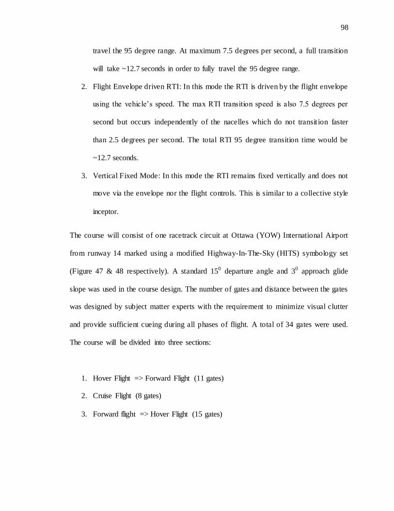
98
98
travel the 95 degree range. At maximum 7.5 degrees per second, a full transition
will take ~12.7 seconds in order to fully travel the 95 degree range.
2. Flight Envelope driven RTI: In this mode the RTI is driven by the flight envelope
using the vehicle’s speed. The max RTI transition speed is also 7.5 degrees per
second but occurs independently of the nacelles which do not transit ion faster
than 2.5 degrees per second. The total RTI 95 degree transition time would be
~12.7 seconds.
3. Vertical Fixed Mode: In this mode the RTI remains fixed vertically and does not
move via the envelope nor the flight controls. This is similar to a collective style
inceptor.
The course will consist of one racetrack circuit at Ottawa (YOW) International Airport
from runway 14 marked using a modified Highway-In-The-Sky (HITS) symbology set
(Figure 47 & 48 respectively). A standard 150 departure angle and 30 approach glide
slope was used in the course design. The number of gates and distance between the gates
was designed by subject matter experts with the requirement to minimize visual clutter
and provide sufficient cueing during all phases of flight. A total of 34 gates were used.
The course will be divided into three sections:
1. Hover Flight => Forward Flight (11 gates)
2. Cruise Flight (8 gates)
3. Forward flight => Hover Flight (15 gates)
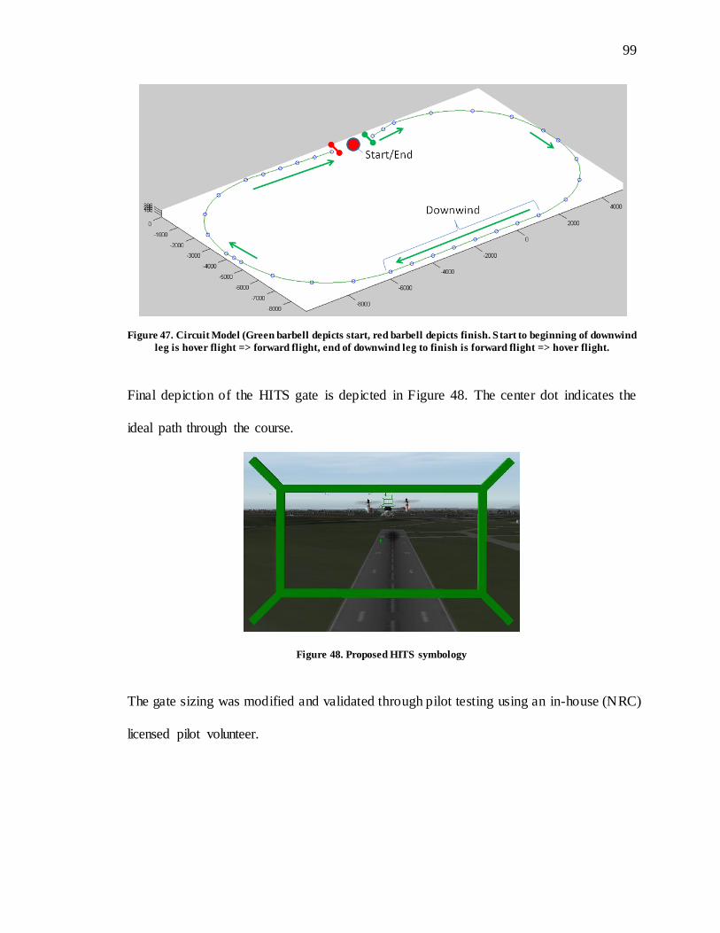
99
99
Figure 47. Circuit Model (Green barbell depicts start, red barbell depicts finish. Start to beginning of downwind
leg is hover flight => forward flight, end of downwind leg to finish is forward flight => hover flight.
Final depiction of the HITS gate is depicted in Figure 48. The center dot indicates the
ideal path through the course.
Figure 48. Proposed HITS symbology
The gate sizing was modified and validated through pilot testing using an in-house (NRC)
licensed pilot volunteer.
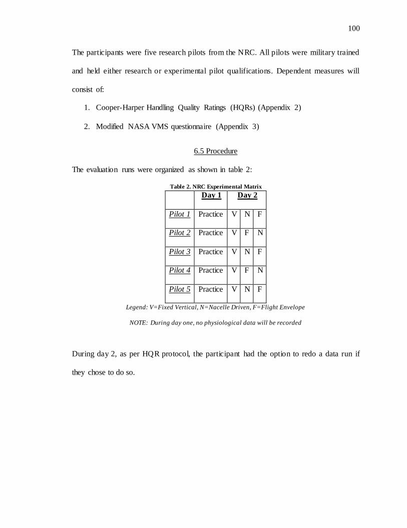
100
100
The participants were five research pilots from the NRC. All pilots were military trained
and held either research or experimental pilot qualifications. Dependent measures will
consist of:
1. Cooper-Harper Handling Quality Ratings (HQRs) (Appendix 2)
2. Modified NASA VMS questionnaire (Appendix 3)
6.5 Procedure
The evaluation runs were organized as shown in table 2:
Table 2. NRC Experimental Matrix
Day 1 Day 2
Pilot 1 Practice V N F
Pilot 2 Practice V F N
Pilot 3 Practice V N F
Pilot 4 Practice V F N
Pilot 5 Practice V N F
Legend: V=Fixed Vertical, N=Nacelle Driven, F=Flight Envelope
NOTE: During day one, no physiological data will be recorded
During day 2, as per HQR protocol, the participant had the option to redo a data run if
they chose to do so.

101
101
6.6 Analysis
As this study is a follow up to the first evaluation done at the NASA Vertical Motion
Simulator (VMS), the same modified NASA VMS questionnaire and Cooper-Harper
Handling Quality Ratings (HQR) scale will be used. The analysis of the HQRs and
questionnaire will be reported in raw format in accordance with the original study.
6.7 Results
In the end, only three of the five NRC test pilots were able to complete the task. One test
pilot indicated after beginning the experiment that he had no rotary wing experience and
was not able to maintain control of the aircraft in the low speed flight regime. Another
pilot was not able to complete the trials due to an RTI failure. The failure rendered the
RTI unavailable to continue further testing and the failure details are discussed in
Appendix 6.
The remaining three evaluation test pilots all had a combination of fixed and rotary wing
backgrounds. HQR results are shown in Table 3:
Table 3. NRC FRL RTI HQR Evaluation Scale
Fixed Vertical Flight Envelope Driven Nacelle Angle Driven
Pilot 1 5 5 4
Pilot 2 3 5 3
Pilot3 4.5 4 4
102
102
In pilot comments, it was suggested that the RTI in Nacelle Angle Driven Mode would be
the most desirable if further training was permitted. One of the confounding factors
within this evaluation was the problematic flight model. Creating a proper tiltrotor flight
model is problematic in that it requires not only a rotary and fixed wing flight model, but
a transition between the two models as well. Due to the complexity of such models, there
are intensive US ITAR regulations that are imposed on them. As the simulation test was
conducted in Canada, it was not possible to obtain a fully compliant model. Instead, a
generic, off-the-shelf model was used.
As proper tiltrotor models are complex, commercially available models get around this
complexity by using a piece-wise model. The deficiencies in these models do not come
from the individual pieces themselves, but the discontinuity between them. In the
evaluation, pilots commented on the increased workload during the transition times. As
the course was relatively short and transitions were the focus of the evaluation, this is
believed to have significant effect on HQR results and pilot comments.

103
103
CHAPTER 7 DISCUSSION AND CONCLUSIONS
The initial drive for this follow on work was to address the control confusion reported in
the VMS phase I experiment by implementing a new control mode called the Flight
Envelope Driven (FED) Mode. By driving the RTI using the flight envelope as a metric
as opposed to the nacelle angle, It was hypothesized that the time in the confusion
causing intermediate area would be reduced, thereby mitigating potential control input
errors.
In distilling the pilot comments, however, it was reported that the FED mode was
considered the least favorable and most confusing of the three. Pilots stated that the FED
mode caused confusion as to where they were in the nacelle range, although comments
did not suggest control movement confusion.
Pilots stated that the FED mode did not provide any new information to them and caused
confusion. The hypothesized reason for this is that the RTI moved in the same manner as
when being driven by the nacelles, but was in fact being driven by an entirely different
variable; airspeed. In one instance a pilot flew the entire course at 730 nacelle because
they stopped transitioning the nacelles forward after the FED mode completed its
conversion to fixed-wing mode. It is this that made me believe that even in the FED
104
104
mode the pilot still considers the RTI to be driven by the nacelles and not the flight
envelope mode.
While the fixed vertical mode provides additional information over the Nacelle Angle
driven mode, it did not provide incongruent information like the FED. Pilots commented
that with additional practice, the Nacelle Angle Driven mode would be the preferred
mode. The reasoning behind this is that the back driven movement may cause confusion
initially because the pilot is not used to it, but through learning, the movement of the RTI
could provide desired additional information about where the nacelles are. In contrast, the
FED mode caused confusion because the movement was not only confusing, but counter
indicative of what the pilot believed to be happening.
The final suggested rank order from comments and HQRs appeared to favor the
following order:
1. Nacelle Angle Driven
2. Fixed Vertical
3. Flight Envelope Driven

105
105
7.1 Discussion
Over the course of the two experiments conducted, no changes were made to the RTI’s
mechanical system itself except to eliminate binding. However, the Design Principle
Hierarchy (DPH) Theory did undergo major changes. Initially the DPH consisted of a
single level:
1. S-R Compatibility
However, a review of other power control inceptors indicated that there was an additional
level that was primary to the S-R Compatibility design constraint, which was ergonomics.
The new DPH was structured as follows:
1. Ergonomics
2. S-R Compatibility
The RTI initially was built using the 2 level structure seen above. At the completion of
the functional prototype build, the RTI underwent phase I testing the NASA VMS. The
testing, indicated that there was confusion during the RTI transitions phases possibly due
to the way pilots add or reduce power with a helicopter collective or airplane throttle.
Through this finding the DPH was updated once again adding a third level. The 3 rd
iteration of the DPH was structured as follows:
1. Ergonomics
2. Proprioceptive Consistency
3. S-R Compatibility
Using the understating garnered from the VMS study, a third mode called Flight
Envelope Driven (FED) mode was created in which the RTI transitioned based on the

106
106
flight envelope as opposed to the nacelles. It was believed that this mode would reduce
the amount of time the pilot was in the range of ambiguity, which caused the reported
initial confusion. In testing this new mode, the evaluation test pilots reported that the new
FED mode, the one created to address the shortcomings of the nacelle angle driven mode,
was in fact less desirable than the nacelle angle driven mode or the fixed vertical mode in
which the RTI did not move. It appears the mismatch of the RTI movement given the
nacelle angle resulted in confusion. Because of this the DPH was updated for a fourth
time to the following structure:
1. Ergonomics
2. S-R Compatibility
3. Proprioceptive Consistency
7.2 Consistency of the DPH with other Power Control Interfaces
The change was initiated after an ordinal effect was noted in mapping the RTI modes and
other existing control systems to the DPH. Table 4 shows the tested RTI modes and other
control systems with respect to the DPH Requirements:
Table 4. DPH Model Evaluation
Ergonomics Mental Model
Proprioceptive Consistency
Notes Rank O rd.
RTI Nacelle Angle Driven 2 of 3 met in order 1
RTI Fixed Vertical 2 of 3 met out of order 2
RTI Flight Envelope Driven Only 1 req met 3
Voith Schnieder Integrated Prop Control 3 of 3 met in order 1
Voith Schnieder Separated Prop Control 2 of 3 met out of order 3
Diesel-Electric Locomotive Throttle 3 of 3 met in order 1
Steam Locomotive Throttle Only 1 req met out of order 2

107
107
Table 4 we see seven different control systems, including the three separate RTI modes.
The rank order (1 being most desirable, 3 being least) is parsed by control grouping
(separated by border boxes). There are three control groups:
1. RTI
2. Voith Schnieder prop control (used for tugboats)
3. Train throttle system
It is believe that both the order in which the three levels are met and the number of total
achieved requirements dictates how suitable the inceptor is. In the case of the RTI, we
can see a positive correlation to the rank order, the DPH ordinal and value effect, and the
comments the pilot’s made concerning the nacelle angle driven mode being the most
desirable while the FED mode was the least. Similarly, the DPH can be applied to
currently existing inceptors such as the Voith Schnieder prop controller and train throttle
systems. In doing so we see that the newer Voith integrated controller fares better over
the separated legacy system and that diesel electric throttle systems are better suited than
the legacy steam controllers.
The reordering of the DPH was not simply done to suit the ordinal and value based
structure of the current theory but was done as a result of the findings on the phase II
work. Initially the current proprioceptive consistency 3rd level, which was previously
level 2, was organized that way because it was thought, due to the elicited comments in
the phase I VMS work that proprioceptive consistency superseded the S-R Compatibility.
This was thought due to the confusion being caused as a result of the intermediate
108
108
transition phase where the RTI switches from a helicopter collective to a throttle. It was
noted that there was a possible bias in the phase I experiment which may have resulted in
to some of the comments. In the phase II experiment the suggested rank order changed
significantly and S-R Compatibility superseded proprioceptive consistency.
7.3 Conclusions Regarding the DPH
In further review of the levels, potential effects can be seen in control system use:
1. Ergonomics: If the ergonomic level is not met, system adoption typically will not
be seen unless there is nothing else to replace it. The reason for this is that the
system would be uncomfortable to use, causing it to be rejected it prior to
mainstream adoption.
2. S-R Compatibility: If the S-R Compatibility requirement is violated, adoption is
possible, although control reversals seem likely. Additional training may be able
to reduce the problem. However, stress reversion can occur, such as seen in
USAF vehicle 5, if negative transfer of training from other systems exists.
3. Proprioceptive Consistency: Much like S-R Compatibility violation, if
proprioceptive consistency is violated, the potential for control reversal also
exists. This, however, is not due to negative transfer of training but instead the
inability to distinguish of which way to move the interface. It is believed however
that with proper training this too can be overcome. It is important to note that in
order to have proprioceptive inconsistency, a third DoF needs to be present. Most
control systems in the world only possess two DoFs making this type of violation
rare.
109
109
The DPH prescribed here is a first cut definition of a potential design guidance principle.
The two evaluations are not exhaustive and caution in interpreting these results is
warranted. The DPH itself is an outline and further research is required to validate it. The
purpose of the DPH is to be used to evaluate future and existing control system designs
from a human factors perspective.

110
110
CHAPTER 8 CONTRIBUTION, CONCLUSIONS, AND FUTURE WORK
8.1 Contribution
The practical impact of this work is expected to be significant. Tiltrotors are part of
military aviation, and will soon be utilized in commercial and general aviation. Until now,
it was not possible to create a functional control inceptor that met the Direction and
Magnitude Framework found in all existing certified western aircraft. The RTI not only
demonstrated this ability but it did so with a ~18% weight savings in the prototype alone
and an estimated 50% weight savings in a production model system. Furthermore, new
variable thrust vehicles are being developed such as the Eurocopter X3, Sikorsky X2, and
the Piasecki SpeedHawk. A fully developed and tested inceptor for such vehicles, with
evidence suggesting its superiority to existing inceptors, would be of great practical
significance.
The theoretical contribution centers on the design principles hierarchy described above.
The identification of the ergonomic consideration, along with the S-R Compatibility and
proprioceptive compatibility requirements, is expected to add clarity to new controller
interface design, particularly for vehicles. In addition, the identification of a new
principle, proprioceptive consistency, is a critical finding not previously described in the
111
111
literature. The resulting three- level set of principles for inceptor/controller design should
provide fundamental guidance to human factors practitioners involved in controller and
inceptor design.
8.2 Conclusions
This work encompasses two significant contributions:
1. Creation of the first DMF conformal power inceptor for tiltrotor aircraft
2. Creation of the first movement specific control design criteria to assist designers,
the DPH.
In completion of the work to this point, it is evident why a conformal tiltrotor power
interface was such a challenge. Work needed to be accomplished in the areas of
mechanical, electrical, and human factors engineering prior to it being possible to create
such a system. While the developed mechanical system is robust, and may even seem
obvious, it took years of work to understand how to provide and relinquish control of
distinct Degrees of Freedom within the system without violating existing design
principles.
While the RTI only possess 3 DoF total, the use of the CPTA principle is generalizable
and can be transferred to other multi DoF designs. This contribution is significant in that
prior to this, power density was the identified technical hurdle and has still yet to be
overcome. The CPTA removed this barrier.

112
112
Tiltrotor flight test is considered by some to be one of the riskiest of all flight test types.
The creation and implementation of the RTI not only trends with the DMF established as
early back as 1910, but also with the direction of the industry. Much like the progression
of early instruments to modern glass displays, the move from a single DoF tiltrotor power
inceptor to a 3 DoF RTI follows this suit in that it also provides additional and relevant
information to the pilot, with the similar goal of reducing workload and increasing safety.
It is believed that the RTI has benefits yet it will take further redesigns and evaluations to
perfect the system for use in tiltrotor aircraft
In parallel to this design and evaluation effort, a structured approach was developed.
While the RTI could have been designed in a void, its integration not only into the flight
deck, but the knowledge base as well was deemed important if not critical. Lack of a
structured approach was necessary, and its importance is evident in the past history of
tiltrotor control interfaces.
There are a number of approaches in control design methodology and evaluation such as
from an aerospace perspective on control harmony, or a mechanical engineering
standpoint on linkage complexity and hysteresis. However, there are none that approach
control design from a human system perspective specifically to the movements of the
control itself. While each perspective may be important by itself, if a control system fails
outside of the existing designed evaluation criteria, the flaw will not only go
undiscovered, but the system could suffer detrimental consequences during its use.
113
113
Much like other design and evaluation methods, the DPH is not intended to be all
encompassing. The focus of the DPH is designed to add an additional layer of evaluation
to augment existing design metrics hopefully leading engineers one step closer to a
systematic and fully encompassing multi-part approach for human in the loop control
design.
8.3 Future Work
Much like the work of this paper, the future work has two focuses that need further
examination. While the RTI suggested benefit, the testing utility of the system itself has
believed to have been exhausted. In order to gain additional data and further evaluate a
conformal throttle interface for tiltrotor aircraft, a new RTI would have to be built and
subsequent flight testing would have to be performed.
Work from a mechanical engineering standpoint needs to be undertaken in order to
identify and address all failure modes. During this the complexity of the RTI needs to be
reduced. The current inception of the system is comprised of over 350 individual parts. In
initial analysis, it is believed that a second generation of RTI could reduce that count
down to less than a hundred. This decrease in mechanical complexity is directly
correlated to the types of failures the system could sustain, a critical factor in flight
worthy systems.
Due to the cost of the RTI and the initial development being primarily self- funded, a
passive counter-weight system was used. In order to implement the RTI in a dual-pilot
114
114
flight deck, an active counterweight and connection system would need to be developed
to conformally link both systems. These systems already implemented in a similar
fashion on the BAE active stick systems, typically cost >$100K per axis on their own
without the full control system itself. In contrast, the RTI cost was ~$60K. The
implementation of an active system would allow each pilot to have an understanding of
what the other was doing by having their RTI mimic the others movements. This is
currently not possible in the RTI’s current inception as the complex rotations do not
allow for a purely mechanical cross linkage.
In order to validate these advancements, additional high-fidelity flight simulations and
actual tiltrotor flight tests would need to occur. This is problematic in that the US military
is the only operator of certified tiltrotor aircraft and with the vehicle being used heavily in
operational theatres, using one for flight test is difficult at best at this time.
In addition to the RTI, the DPH needs further evaluation. The current inception of the
hierarchy has been developed solely under the pretense of tiltrotor power inceptors.
While the DPH is designed to evaluate such inceptors, the true test of the DPH would be
evaluations for current and future inceptor designs with operational testing and
longitudinal tracking of said inceptors performance.
While entirely new control designs are rare, NASA is currently looking at new control
concepts for the lunar and mars lander vehicles, each of which have multiple DoF
systems. Earthbound, both Sikorsky and Eurocopter are developing new multi-DoF
115
115
VTOL aircraft that will require new control interface systems. Any of these new systems
could be evaluated by the DPH to see if it holds up to non-tiltrotor systems.
Regardless of what system it is tested on, the DPH will need to be evaluated further on
both new and existing ones in order to validate its claims. Even through the design
process and two evaluations, the DPH changed its form each time. Without the
understanding of how other evaluations would affect its structure, it is not possible to say
if the qualities and order of them are properly laid out.

REFERENCES
116
116
REFERENCES
Airworthiness Standards: Transport Category Rotorcraft, F.A.R. §23.779 (1996). FAA.
Airworthiness Standards: Transport Category Rotorcraft, F.A.R. §25.779 (1990). FAA.
Airworthiness Standards: Transport Category Airlines, F.A.R. §27.779 (1984a). FAA.
Airworthiness Standards: Transport Category Rotorcraft, F.A.R. §29.779 (1984b). FAA.
Andre, A.D., Haskell, I., & Wickens, C.D. (1991). S-R compatibility effects with
orthogonal stimulus and response dimensions. In Proceedings of the Human Factors
Society 35th Annual Meeting (pp. 1546-1550). Santa Monica, CA: Human Factors Society.
BA609 Images. (2008). Retrieved April 5, 2008, from
http://www.bellagusta.com/airbagallery.cfm
Bell XV-3. (2011). Retrieved January 7, 2011, from http://pixdaus.com/pics/
1240945990SYg9mYh.jpg

117
117
Bertelson, P. (1963). S-R relationships and reaction times to new versus repeated signals
in a serial task. Journal of Experimental Psychology, 65, 478-484.
Boulet, J. (1984). History of the helicopter as told by its pioneers 1907-1956. (1st ed.).
Editions France-Empire.
Cantrell, M. (2007, January). Osprey rising. Military Officer MOAA, 50-55.
Deckert, W. H., & Ferry, R. G., (1960). Limited flight evaluation of the XV-3 aircraft.
(AFFTC-TR-60-4).
Dugan, D. (1998). Designing the V-22 tiltrotor: a flight test pilot’s perspective. Vertiflite
Summer, 44(3), 32-36.
Dugan, D. (2008). Magnum Controller, Jim Cheatem
Fisher, J. (2009) XC-142 Flight Deck, Wright Patterson Air Force Base.
Fitts, P.M., & Seeger, C.M. (1953). S-R compatibility: Spatial characteristics of stimulus
and response codes. Journal of Experimental Psychology, 46(3): 199-210.

118
118
Harrier Throttle Quadrant (2011). Retrieved February 3rd, 2011, from
http://simhq.com/forum/ubbthreads.php/topics/2141214/ReHarrierthrottleandnozzl
e.html
Haverdings, H. (2009). U.S. Patent Pending. Washington, DC: U.S. Patent and
Trademark Office.
Motorcycle Grip. (2011). Retrieved January 7, 2011, from
http://www.superbike.co.uk/imageBank/h/hot%20grips%20Bandit.jpg
Proctor, R. W., & Reeve, T. G., (1990). Stimulus-Response Compatibility. Amsterdam
North-Holland.
Proctor, R. W., & Vu, K. L. (2006). Stimulus-response compatibility principles. (1st ed.),
Florida: Taylor & Francis.
Rozovski, D., (2008a). Control Reversal Mitigation and Situational Awareness
Improvement for Tiltrotor Aircraft Pilots via Redesign of the Thrust/Power Control
Interface. Unpublished master thesis, University of Illinois, Urbana-Champaign, Illinois.
Rozovski, D. (2008b). U.S. Patent Pending. Washington, DC: U.S. Patent and Trademark
Office.

119
119
Rozovski, D., & Theodore, C. R. (2011). Evaluation of the rotational throttle interface
for converting aircraft utilizing the NASA Ames vertical motion simulator. American
Helicopter Society 67th Annual Forum, Virginia Beach, VA.
V-22 Osprey. (2011, January 7). Retrieved January 7, 2011, from
http://www.military-today.com/helicopters/bellboeingv22osprey.jpg
Vince, M. A., & Mitchell, M. J. H. (1946). Direction of movement of machine controls.
II. Ministry of Supply Report No. SM 2861.
Wickens, C.D. & Hollands, J.G. (2000) Engineering psychology and human performance
(3rd ed.). New Jersey: Harper Collins.
XV-15 tilt rotor takeoff – first NASA Dryden flight. (2002, February 6). Retrieved April 5,
2008, from http://www.dfrc.nasa.gov/gallery/photo/XV-15/HTML/ECN-13850.html

APPENDICES
120
120
Appendix A
Pilot Questionnaire
Task Performance
1. Describe ability to meet DESIRED / ADEQUATE performance standards.
2. Describe aggressiveness / precision with which task is performed.
3. If trying for DESIRED performance resulted in unacceptable oscillations, did decreasing your goal to
ADEQUATE performance alleviate the problem?
Aircraft Characteristics
4. Describe any objectionable controller force or motion characteristics, particularly with the Thrust
Controller (TCL).
5. Describe predictability of initial aircraft response and ability to precisely control thrust.
6. Describe any objectionable oscillations or tendency to overshoot.
7. Describe any non-linearity of TCL response.
Demands on the Pilot
8. Describe overall TCL control strategy in performing the task (cues used, scan, etc.).
9. Describe any control compensation you had to make to account for deficiencies in the aircraft or TCL.
10. Describe any modifications you had to make to what you would conside r “normal” Thrust control
technique in order to make the aircraft behave the way you wanted.
Miscellaneous
11. How natural were the TCL inceptor motions required to perform the task?
12. Were there any undesirable characteristics of the Thrust Controller?

121
121
13. (RTI only) Did the rotation of the RTI with nacelle angle make it easier or harder to accomplish the
maneuver?
14. (RTI only) Comment on the suitability of using position of the RTI arm and grip as a cue of nacelle
position.
15. Comment on anything else related to the TCL.
Assign HANDLING QUALITIES RATING for overall task.
16. Using the Cooper-Harper rating scale, please highlight your decision-making process and adjectives
that are best suited in the context of the task. If assigned HQR is Level 2, briefly summarize any
deficiencies that make this configuration unsuitable for normal accomplishment of this task, i.e., justify
why the procuring activity should reject this configuration as a means to accomplish this task.
17. What was the critical sub-phase of the task (e.g., entry, steady-state, exit) or major determining factor in
the overall Handling Quality Rating (HQR) – with respect to the Thrust Controller?
18. Did the Thrust Controller have a significant impact on the assigned HQR?
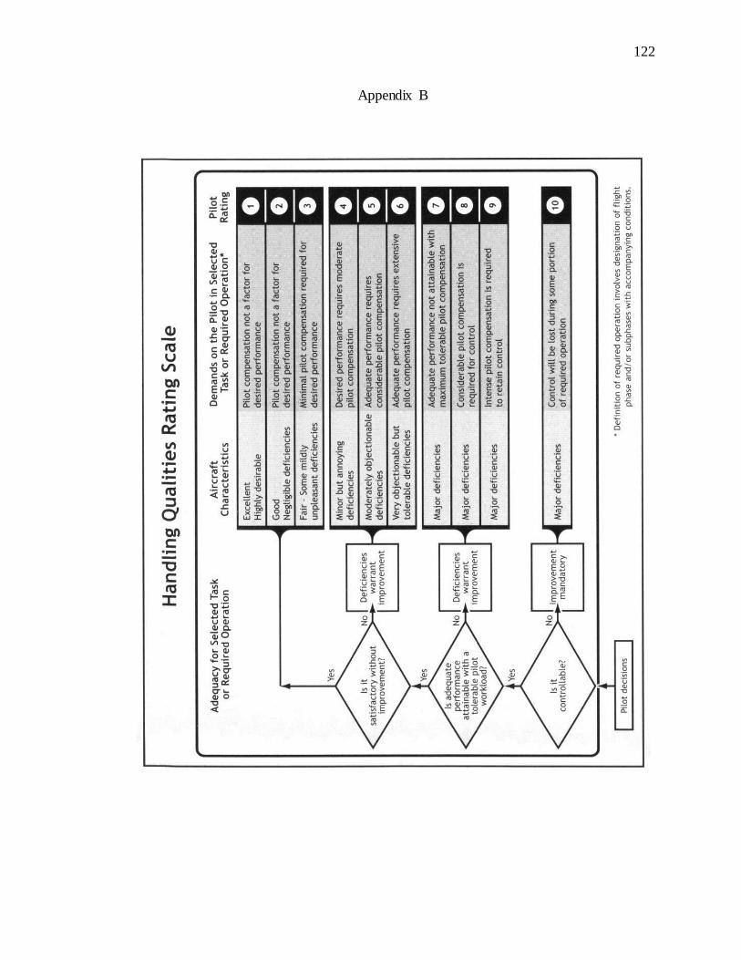
122
122
Appendix B
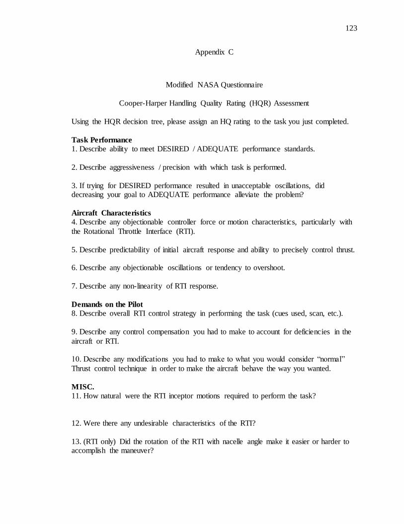
123
123
Appendix C
Modified NASA Questionnaire
Cooper-Harper Handling Quality Rating (HQR) Assessment
Using the HQR decision tree, please assign an HQ rating to the task you just completed.
Task Performance
1. Describe ability to meet DESIRED / ADEQUATE performance standards.
2. Describe aggressiveness / precision with which task is performed.
3. If trying for DESIRED performance resulted in unacceptable oscillations, did decreasing your goal to ADEQUATE performance alleviate the problem?
Aircraft Characteristics
4. Describe any objectionable controller force or motion characteristics, particularly with
the Rotational Throttle Interface (RTI).
5. Describe predictability of initial aircraft response and ability to precisely control thrust. 6. Describe any objectionable oscillations or tendency to overshoot.
7. Describe any non-linearity of RTI response.
Demands on the Pilot
8. Describe overall RTI control strategy in performing the task (cues used, scan, etc.).
9. Describe any control compensation you had to make to account for deficiencies in the
aircraft or RTI. 10. Describe any modifications you had to make to what you would consider “normal”
Thrust control technique in order to make the aircraft behave the way you wanted.
MISC.
11. How natural were the RTI inceptor motions required to perform the task?
12. Were there any undesirable characteristics of the RTI?
13. (RTI only) Did the rotation of the RTI with nacelle angle make it easier or harder to accomplish the maneuver?

124
124
14. (RTI only) Comment on the suitability of using position of the RTI arm and grip as a cue of nacelle position.
15. Comment on anything else related to the RTI.
Assign HANDLING QUALITIES RATING for overall task.
16. Using the Cooper-Harper rating scale, please highlight your decision-making process
and adjectives that are best suited in the context of the task. If assigned HQR is Level 2, briefly summarize any deficiencies that make this configuration unsuitable for normal
accomplishment of this task, i.e., justify why the procuring activity should reject this configuration as a means to accomplish this task.
17. What was the critical sub-phase of the task (e.g., entry, steady-state, exit) or major determining factor in the overall Handling Quality Rating (HQR) – with respect to the
RTI? 18. Did the RTI have a significant impact on the assigned HQR?

125
125
Appendix D
NRC-FRL Performance Standards
RTI Trial HQR Criteria
1. Gate Criteria: There is a 4-gate tolerance over the entire course. Desired: < 4 Gates Missed Adequate: > 4 Gates Missed
2. Pitch Attitude Criteria: There is a vehicle pitch attitude tolerance over the
course of the flight. Desired: Pitch Attitude = 10 Deg. Adequate: Pitch Attitude = 15 Deg.
3. Downwind Leg Velocity Criteria: There is a flight velocity tolerance for the
downwind leg. Desired: Velocity = 250 kts. +/- 2 kts. Adequate: Velocity = 250 kts. +/- 4 kts.
4. Cyclic control stop criteria: There is a time based tolerance for cyclic control
over the flight. Desired: 3 seconds at cyclic stop Adequate: 8 seconds at cyclic stop
5. Landing Criteria: There are both landing spot and landing success tolerances for
the flight.
A. Landing Spot
Desired: Before threshold markings Adequate: Between threshold marking and runway intersection
B. Landing Success
All Crash Scenarios: HQR > 7

126
126
Appendix E
NRC-FRL Questionnaire
Task Performance
1. Describe ability to meet DESIRED / ADEQUATE performance standards.
2. Describe aggressiveness / precision with which task is performed.
3. If trying for DESIRED performance resulted in unacceptable oscillations, did decreasing your goal to ADEQUATE performance alleviate the problem?
Aircraft Characteristics
4. Describe any objectionable controller force or motion characteristics, particularly with
the Thrust Controller (TCL).
5. Describe predictability of initial aircraft response and ability to precisely control thrust. 6. Describe any objectionable oscillations or tendency to overshoot.
7. Describe any non-linearity of TCL response.
Demands on the Pilot
8. Describe overall TCL control strategy in performing the task (cues used, scan, etc.).
9. Describe any control compensation you had to make to account for deficiencies in the
aircraft or TCL. 10. Describe any modifications you had to make to what you would consider “normal”
Thrust control technique in order to make the aircraft behave the way you wanted.
MISC.
11. How natural were the TCL inceptor motions required to perform the task?
12. Were there any undesirable characteristics of the Thrust Controller?
13. (RTI only) Did the rotation of the RTI with nacelle angle make it easier or harder to accomplish the maneuver?
14. (RTI only) Comment on the suitability of using position of the RTI arm and grip as a cue of nacelle position.
15. Comment on anything else related to the TCL.

127
127
Assign HANDLING QUALITIES RATING for overall task.
16. Using the Cooper-Harper rating scale, please highlight your decision-making process
and adjectives that are best suited in the context of the task. If assigned HQR is Level 2, briefly summarize any deficiencies that make this configuration unsuitable for normal
accomplishment of this task, i.e., justify why the procuring activity should reject this configuration as a means to accomplish this task.
17. What was the critical sub-phase of the task (e.g., entry, steady-state, exit) or major determining factor in the overall Handling Quality Rating (HQR) – with respect to the
Thrust Controller? 18. Did the Thrust Controller have a significant impact on the assigned HQR?
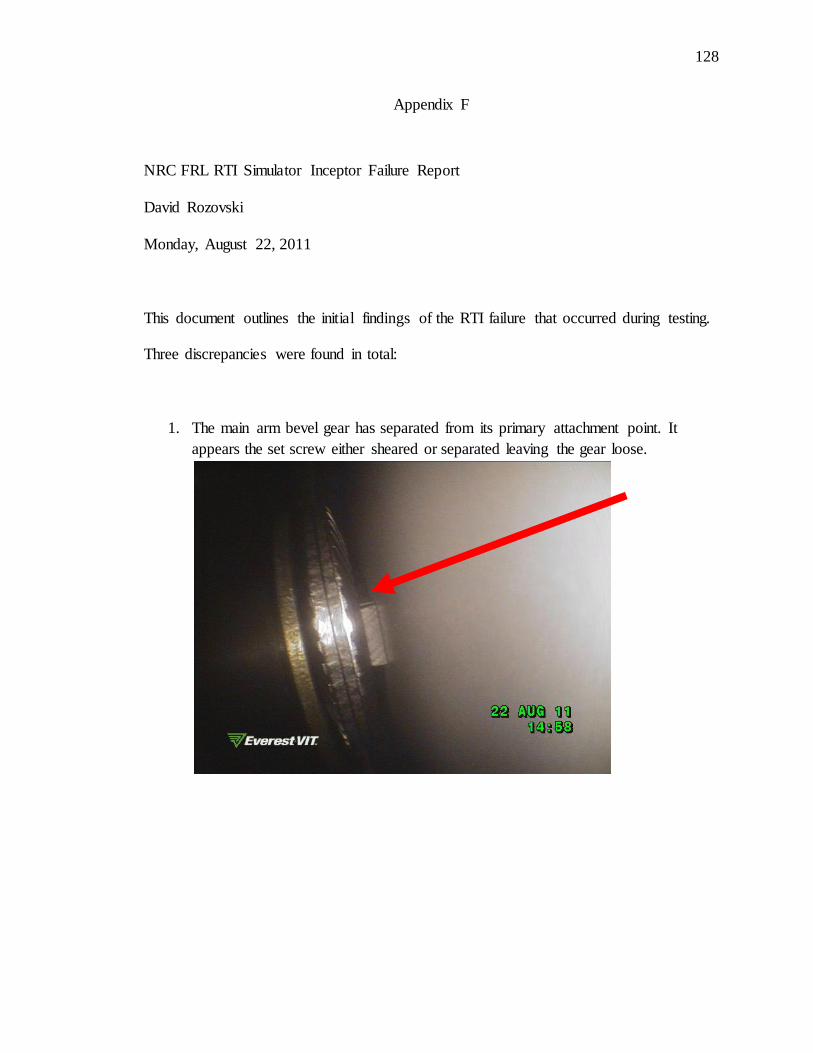
128
128
Appendix F
NRC FRL RTI Simulator Inceptor Failure Report
David Rozovski
Monday, August 22, 2011
This document outlines the initial findings of the RTI failure that occurred during testing.
Three discrepancies were found in total:
1. The main arm bevel gear has separated from its primary attachment point. It
appears the set screw either sheared or separated leaving the gear loose.
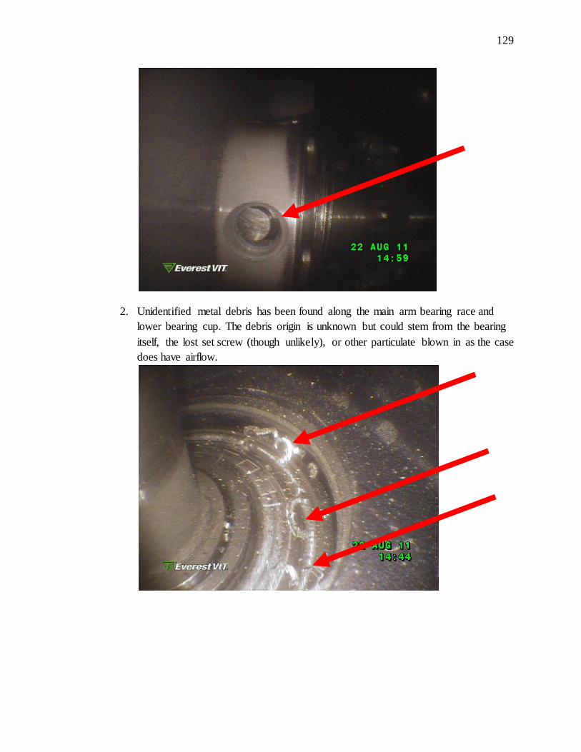
129
129
2. Unidentified metal debris has been found along the main arm bearing race and
lower bearing cup. The debris origin is unknown but could stem from the bearing
itself, the lost set screw (though unlikely), or other particulate blown in as the case
does have airflow.
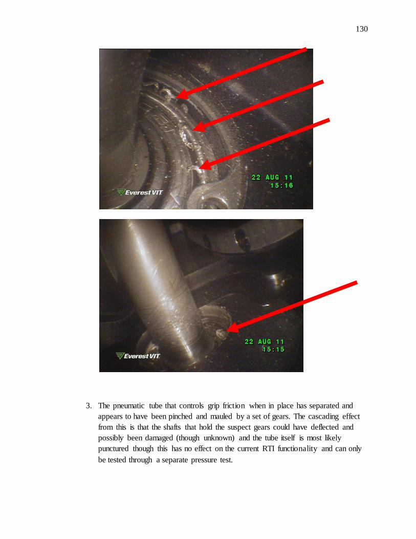
130
130
3. The pneumatic tube that controls grip friction when in place has separated and
appears to have been pinched and mauled by a set of gears. The cascading effect
from this is that the shafts that hold the suspect gears could have deflected and
possibly been damaged (though unknown) and the tube itself is most likely
punctured though this has no effect on the current RTI functionality and can only
be tested through a separate pressure test.
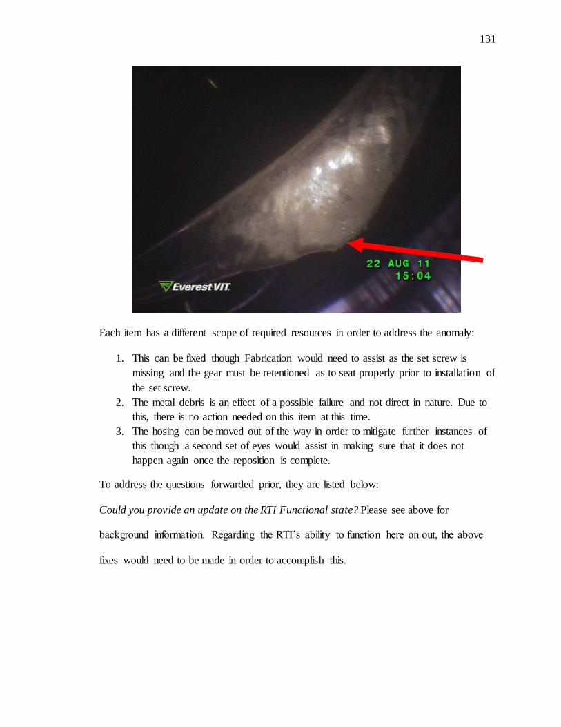
131
131
Each item has a different scope of required resources in order to address the anomaly:
1. This can be fixed though Fabrication would need to assist as the set screw is
missing and the gear must be retentioned as to seat properly prior to installation of
the set screw.
2. The metal debris is an effect of a possible failure and not direct in nature. Due to
this, there is no action needed on this item at this time.
3. The hosing can be moved out of the way in order to mitigate further instances of
this though a second set of eyes would assist in making sure that it does not
happen again once the reposition is complete.
To address the questions forwarded prior, they are listed below:
Could you provide an update on the RTI Functional state? Please see above for
background information. Regarding the RTI’s ability to function here on out, the above
fixes would need to be made in order to accomplish this.
132
132
Has the device been assessed and a failure-mode identified? Yes
How long will it take to repair it? If these are the only issues, I estimate one (1) to two (2)
weeks.
Can the repaired device be utilized reliably for NRC simulator trials assumed to require
another 25-hours of operation? I honestly do not know the answer to this. I am surprised
that the RTI has both made it this far and has had the failures it has. None of the issues
listed above were in my immediate scope of concern, I was more concerned about the
shaft flex and breakage so it is hard to make an estimation on this question. I can say I
certainly hope so.
Please let me know if you have any further questions. Thank you.
Sincerely,
David Rozovski

VITA
133
133
VITA
David Rozovski Academic Education
Ph.D. Industrial Engineering – Aviation Human Factors Purdue University - West Lafayette, IN, USA, December 2013
Doctoral Thesis; Human Factors Engineering & Control Design Research; “Design, Development, and Testing of a Conformal Power Control Interface for
Thrust Vectoring Aircraft”
M.S. Human Factors University of Illinois - Urbana-Champaign Urbana, IL, USA, May 2008
Master’s Thesis; Human Factors Engineering & Control Theory Research; “Control-Reversal Mitigation and Situational Awareness Improvement for
Tiltrotor Aircraft Pilots via Redesign of the Thrust/Power Control Interface”
B.S. Psychology
Linfield College - McMinnville, OR, USA, January 2005
Senior Thesis; Aviation Psychology and Human Factors Research: “Vacuum Failure Detection and Visual Factors that Affect Pilot Recognition Times in IMC
Conditions for Single Engine Aircraft”
Aeronautic Education
Multi-Engine Commercial Rating - West Lafayette, IN, USA, October 2010
Commercial (Fixed-Wing) Certificate - West Lafayette, IN, USA, October 2010
Chilean Fixed-Wing Instrument Rating Validation - Santiago, Chile, May 2010
Complex Endorsement - West Lafayette, IN, USA, June 2009
Instrument (Fixed-Wing) Rating - West Lafayette, IN, USA, May 2009
High-Performance Endorsement - Hayward, CA, USA, July 2006
Chilean Helicopter PPL Validation - Santiago, Chile, March 2006
Helicopter Private Pilot Certificate - Newberg, OR, USA, September 2005
Chilean Fixed-Wing PPL SEL Validation - Santiago, Chile, March 2005
Tail-wheel Endorsement - McMinnville, OR, USA, September 2004
Basic Aerobatics Maneuver Course - McMinnville, OR, USA, May 2004
Fixed-Wing Private Pilot Certificate SEL - McMinnville, OR, USA, April 2004
134
Aircraft Flown To Date
33 Distinctive Types (28 fixed-wing / 5 rotary-wing)
515 Hours (385 hours fixed-wing / 130 hours rotary-wing)
Military Aircraft Bell TH-57B/C Sea Ranger Beechcraft T-6A Texan II
North American T-28 Trojan North American T-6 Texan
Naval Aircraft Factory N3N Experimental Aircraft
Bell 205 NRC Fly-By-Wire Bell 206 Instrumented Platform
Extra 300L Instrumented Platform Rotary-Wing
Eurocopter EC-120 Schweizer 300C/CBi
Hughes 269 Multi-Engine Fixed-Wing
Ford 5-AT-B Tri-Motor (1933) Beechcraft Baron B-58E
Piper Seneca PA-34 Aerobatic Fixed-Wing
Yakovlev Yak-52 American Champion Citabria
Fixed-Wing Civilian Single Engine Land Cirrus SR-20 Beechcraft Bonanza BE-36
Piper Tomahawk PA-38 Cherokee PA-28
Arrow PA-28 Archer PA-28
Diamond DA-40
Cessna C-150 C-152 Aerobat
C-172 Skyhawk C-182 Skylane C-185 Skywagon
C-206 Super Skywagon C-T-210 Turbo Centurion
Fixed-Wing Gliders Grob G 103 Twin Astir
Xiamango Motor Glider Schweizer 2-33