Embed Size (px)
DESCRIPTION
Design delivrables
Citation preview

7/21/2019 Design Deliverables
http://slidepdf.com/reader/full/design-deliverables 1/11
UM Design Deliverables Page 1 of 11
DESIGN DELIVERABLES APRIL 2014
As part of the deliverables for formal UM review at each of the major phases of design listed below, the Design Professional shall submit this"Design Deliverables" document to the University's Design Coordinator. On the "Design Deliverables" document, the Design Professional shallindicate the status of each required item (a check mark is interpreted to mean that an item has been included in the deliverables). On or attached tothe "Design Deliverables" document, the Design Professional shall identify all items NOT included in the review package.
Note that design deliverables for the Design Development phase are to include all items listed in the Design Development column of the "DesignDeliverables" table AND, except as specifically stated to the contrary in the table, all items listed in the Schematic Design column of the table (whichare to have been further developed during Design Development).
Note that design deliverables for the Construction Document phase are to include all items listed in the Construction Document column of the"Design Deliverables" table AND, except as specifically stated to the contrary in the table, all items listed in the Schematic Design column and allitems listed in the Design Development column of the table (which are to have been further developed during the Construction Document phase).
ITEM SCHEMATIC PHASE DESIGNDEVELOPMENT
PHASE
CONSTRUCTION DOCUMENT
PHASE
G ENERAL D ESCRIPTION
1. Scope of work narrative
2. Comparison of capacities (see"Building Interior" for area
comparison) to program 3. List of applicable building codes
on drawing title sheet
4. Building code review (describemeans of compliance for majorcode issues and building systems)
5. List of anticipated building codevariance requests
6. Anticipated building and spaceoccupancy schedules
(continued)
14. Description of construction phasing
15. Description of any proposed occupancywithin construction area
16. Description of water & vaporcharacteristics of roof & exterior walls
17. Documentation on drawings asrequired by building codes (specifically toinclude indication of maximum allowable
number of people in each room) 18. List of all code variances (on drawings
cover sheet)
19. When special inspection or testing isrequired by building code, a separately
bound “Statement of Special Inspections”as stipulated by building code
20. If multiple bid packages, clearindication of scope of each release
(continued)
7/21/2019 Design Deliverables
http://slidepdf.com/reader/full/design-deliverables 2/11
UM Design Deliverables Page 2 of 11
ITEM SCHEMATIC PHASE DESIGNDEVELOPMENT
PHASE
CONSTRUCTION DOCUMENT
PHASE
G ENERAL D ESCRIPTION
(continued)
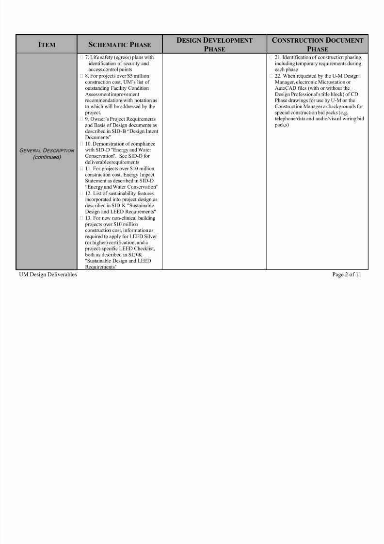
7. Life safety (egress) plans withidentification of security andaccess control points
8. For projects over $5 millionconstruction cost, UM’s list ofoutstanding Facility ConditionAssessment improvementrecommendations with notation asto which will be addressed by the
project.
9. Owner’s Project Requirementsand Basis of Design documents as
described in SID-B “Design IntentDocuments”
10. Demonstration of compliancewith SID-D "Energy and WaterConservation". See SID-D fordeliverables requirements
11. For projects over $10 million
construction cost, Energy ImpactStatement as described in SID-D“Energy and Water Conservation"
12. List of sustainability features
incorporated into project design asdescribed in SID-K "SustainableDesign and LEED Requirements"
13. For new non-clinical building projects over $10 millionconstruction cost, information asrequired to apply for LEED Silver(or higher) certification, and a
project-specific LEED Checklist, both as described in SID-K"Sustainable Design and LEED
Requirements"
21. Identification of construction phasing,including temporary requirements duringeach phase
22. When requested by the U-M DesignManager, electronic Microstation orAutoCAD files (with or without theDesign Professional's title block) of CDPhase drawings for use by U-M or theConstruction Manager as backgrounds forspecial construction bid packs (e.g.telephone/data and audio/visual wiring bid
packs)

7/21/2019 Design Deliverables
http://slidepdf.com/reader/full/design-deliverables 3/11
UM Design Deliverables Page 3 of 11
ITEM SCHEMATIC PHASE DESIGNDEVELOPMENT
PHASE
CONSTRUCTION DOCUMENT
PHASE
S PECIFICATIONS
1. System & material narrativedescription
2. Outline or preliminary specificationsindicating project specific features of majorequipment as well as component materials,e.g. “welded Schedule 40 steel pipe”,“quarter sawn oak”, etc. w/ same sectionnumbering as final specification
3. Complete specification including draftfront end documents
4. List of items which are sole-sourced ordual-sourced and justification for notspecifying three acceptable products
5. For items listed in UM's "PreferredManufacturers List", a table of specifieditems that are NOT indicated in UM'sPML, and the justification for specifyingthese items
6. For door hardware sets that requireelectricity, indicate the proposed sequence
of operations for the hardware
S I TE
1. Site plans, to include thefollowing: a. Existing conditions
b. Demolitionc. Building outline(s)d. Future expansione. Site entrancef. Roads & drivewaysg. Parking locationsh. Bus stop/shelter (if required)
i. Loading dock location j. Waste/recycling collectionlocationsk. Walkway locationsl. Stairway locationsm. Emergency telephone locationsn. Utility requirementso. Site utilities
p. Preliminary grading planq. Soil retention work, if needed
(continued)
5. General dimensions & elevations
6. Permanent exterior signage
7. Parking/roadway plans & elevations
8. Vehicle & pedestrian traffic controls (ifrequired)
9. Grading plan
10. Site lighting plans, simulations,specifications, equipment cut sheets and
photometrics (as defined in DesignGuideline 16521)
11. Concept details of site fixtures &equipment
12. Utility plans, elevations & details forlocal governing agency approval
13. Sanitary sewer flow calculations forOSEH approval
14. Plan to address existinghazardous/contaminated materials, ifapplicable
(continued)
18. Extent of construction area
19. Area traffic plan, if existingroads/walks are impacted
20. Site development phasing
21. Construction site access
22. Staging area
23. Construction signage
24. Site details, including hardscape
25. Profiles for underground utilities
26. Pipe sizes
27. Connection details
28. Copy of local government reviewcomments on utilities and modifications inright(s)-of-way

7/21/2019 Design Deliverables
http://slidepdf.com/reader/full/design-deliverables 4/11
UM Design Deliverables Page 4 of 11
ITEM SCHEMATIC PHASE DESIGNDEVELOPMENT
PHASE
CONSTRUCTION DOCUMENT
PHASE
S I TE
(continued)
2. Site plan for public use (seeSID-H)
3. Storm water management plan
4. Preliminary site lighting plan
15. Soil erosion and sedimentation control plan (for both construction and occupancy)
16. Soil erosion and sedimentation control"Design & Review Checklist" described inUM Design Guidelines Section 02215
17. Dewatering plan
L ANDSCAPING
1. Existing conditions
2. Landscaping concept
3. Existing irrigation
4. Planting plan
5. Irrigation plan
6. Protection for existing trees andsignificant plantings during construction
7. Soil preparation & plantingspecifications
8. Guying diagrams
9. Piping diagrams
10. Pipe sizes 11. Landscape and irrigation details and
legends
S TRUCTURAL
1. Structural scheme plans
2. Written description
3. Foundation plan
4. Typical floor framing plan
5. Framing plans at unique features
6. Main member sizing
7. Structural sections
8. Definition of control joints
9. Beam, column & slab schedules
10. Mechanical and electrical concretehouse keeping pads
11. Foundation details
12. Structural details
13. Structural notes
14. Structural calculations
B UILDING E XTERIOR
E NVELOPE
1. Typical elevations
2. Fenestration layout
3. Material designations
4. Overall building cross-sections
5. Roof layout
6. All building elevations w/dimensionalheights
7. Typical wall sections
8. Parapet & coping details
9. Roof & drainage plan
10. Exterior door details
11. Typical window details
12. Details of unique features
13. Expansion joint locations
14. Large scale building cross-sections
15. Roof-mounted equipment
16. Roof details
17. Exterior details
18. Flashing details
19. Control joint definition & details

7/21/2019 Design Deliverables
http://slidepdf.com/reader/full/design-deliverables 5/11
UM Design Deliverables Page 5 of 11
ITEM SCHEMATIC PHASE DESIGNDEVELOPMENT
PHASE
CONSTRUCTION DOCUMENT
PHASE
B UILDING I NTERIOR
1. Typical floor plans (min 1/16"scale) w/ legends
2. Floor plans for room numbering& public use (see SID-H)
3. Demolition plans
4. All room numbers (comply withDesign Guidelines Section 10400)
5. Area use identification & area insquare ft.
6. Mechanical, electrical & otherservice closets & rooms
7. Circulation paths
8. Area tabulations compared to program requirements
9. Show flexibility for expansion& alterations
10. Preliminary layout of majorspaces w/ fixed equipment
11. All floor plans (min 1/16" scale)
12. Enlarged plans at elevation changes(such as stairs
13. Enlarged plans at toilet rooms
14. Reflected ceiling plans
15. Wall types, fire ratings, smoke controlzones
16. Plan to address existing hazardousmaterials, if applicable
17. Fixed seating
18. Defined seating, serving, & kitchenfacilities
19. Equipment & furniture layouts 20. Important interior elevations
21. Details of unique features
22. Details of fixed equipment
23. Preliminary finish schedule
24. Preliminary door schedule
25. Informational signage
26. Dimensioned floor plans
27. Enlarged plans
28. Partition details
29. Interior details
30. Interior elevations
31. Finish schedules
32. Door & hardware schedules
33. Room signage
34. Schedule of proposed movableequipment that is NOT indicated ondocuments (for reference)
35. Schedule of lab fixtures (turrets, etc.),
if applicable
E LEVATORS
1. Elevator locations
2. Equipment room locations
3. Elevator shaft section
4. Equipment description
5. Dimensioned plans
6. Sections & details of hydrauliccylinder, if applicable
7. Description of shaft sump pits
8. Elevator car & equipment supportdetails
9. Description of controls & fixtures
10. Door & frame details
11. Interior details including lighting
HVAC
1. Identify all systems (continued)
9. Overall building air flow diagram
indicating air handlers, exhaust fans, duct
risers, and duct mains
(continued)
21. Detailed piping and duct design with
all sizes indicated (continued)

7/21/2019 Design Deliverables
http://slidepdf.com/reader/full/design-deliverables 6/11
UM Design Deliverables Page 6 of 11
ITEM SCHEMATIC PHASE DESIGNDEVELOPMENT
PHASE
CONSTRUCTION DOCUMENT
PHASE
HVAC
(continued)
2. One-line diagrams for each air,hydronic, steam, condensate andall other HVAC related systems,and other materials as required todescribe the fundamental designconcept for all mechanical systems
3. Indication of the amount ofredundancy for all major pieces ofmechanical equipment, e.g. “two
pumps 100% capacity each”
4. Major equipment locations
5. Air intake & discharge locations
6. Gross HVAC zoning, andtypical individual space zoning(e.g. VAV boxes per office =?)
7. Mechanical legend
8. Special occupancy zones
10. Plans indicating shaft, chase, recessrequirements
11. Duct layout for typical spaces
12. Equipment schedules (majorequipment)
13. Equipment locations (w/enlargedmechanical plans)
14. Indication of typical locations of firedampers, smoke dampers, and combinationF/S dampers
15. Control diagrams (concept form) for all
mechanical and plumbing systems 16. Outline of major control sequences of
operation
17. M/E smoke control schemes
18. Preliminary floor plans of mechanicalrooms w/all components and requiredservice access areas drawn to scale
19. Preliminary calculations
20. Meter locations and types
22. Floor plans w/ all components andrequired service access areas drawn toactual scale. On the plans, indicate ductsizes and air flow quantities relative toeach room, including CFM in and out ofall doors. Indicate location of control
panels
23. Lab air valves and volume control boxes (note that each is to be identified by a unique number assigned by theengineer). Provide a schedule thatindicates the control sequence that appliesto each room (room #, room descriptor,control sequence #)
24. Detailed floor plans of mechanicalrooms w/ all components and requiredservice access areas drawn to actual scale
25. Cross-sections through mechanicalrooms and areas where there areinstallation/coordination issues (tightspace, zoning of utilities). Indicaterequired service access areas
26. In common mechanical space,
indication of space zoning by system
27. Connection to fire alarm & campuscontrol systems
28. Equipment details, includingstructural support requirements
29. Penetration/sleeve details
30. Installation details
31. Duct construction schedule (on thedrawings), indicating materials and
pressure class for each duct system (continued)

7/21/2019 Design Deliverables
http://slidepdf.com/reader/full/design-deliverables 7/11
UM Design Deliverables Page 7 of 11
ITEM SCHEMATIC PHASE DESIGNDEVELOPMENT
PHASE
CONSTRUCTION DOCUMENT
PHASE
HVAC
(continued)
32. Detailed controls drawings, includingclear differentiation of traderesponsibility for control, fire, and control
power wiring
33. Detailed sequences of operationincluding the specific setpoints for allcontrol loops that will result in attainmentof the required design criteria, as well asalarm setpoints and time delays
34. Design calculations
P LUMBING & P IPING
1. One-line (riser) diagrams forevery plumbing system (e.g.
domestic water, sanitary, storm,gas, RODI, etc.) and othermaterials as required to describethe fundamental design concept forall plumbing systems
2. Indication of the amount ofredundancy for all major pieces ofmechanical equipment, e.g. “two
pumps 100% capacity each”
3. Main water supply, storm, andsanitary leads
4. Major equipment locations 5. Restroom location(s)
6. Plumbing legend
7. Updated design criteria for each plumbing system (including set points,
water quality levels, etc.)
8. Preliminary piping plans (domestic & process) with indication of required serviceaccess areas
9. Meter locations
10. Back flow prevention locations
11. Fixture schedules, to include labfixtures
12. Equipment schedules (majorequipment)
13. Preliminary floor plans of mechanical
rooms w/all components and requiredservice access areas drawn to scale
14. Water riser diagram, includingassumed fixture counts per floor
connection
15. Waste and vent riser diagramsincluding assumed fixture counts perfloor connection
16. Foundation drains
17. Detailed piping design with all pipesizes indicated
18. Typical plumbing details, includingstructural support requirements
19. Water heating piping details
20. Penetration/sleeve details
21. Design calculations
F IRE P ROTECTION
(M ECHANICAL )
1. One-line diagrams for each fire protection system, and othermaterials as required to describethe fundamental design concept forall fire protection systems
2. Report documenting adequacyof utility
(continued)
7. Location of test headers and firedepartment connections
8. Preliminary piping plans
9. Preliminary floor plans of mechanicalrooms w/all components and requiredservice access areas drawn to scale
10. Fire pump sizing calculations
11. Fire protect. service entrance details
12. Fire protection plans (incl. header andriser layout) with indication of anyrequired service access areas
13. Detailed piping design with all major pipe sizes indicated
(continued)

7/21/2019 Design Deliverables
http://slidepdf.com/reader/full/design-deliverables 8/11
UM Design Deliverables Page 8 of 11
ITEM SCHEMATIC PHASE DESIGNDEVELOPMENT
PHASE
CONSTRUCTION DOCUMENT
PHASE
F IRE P ROTECTION
(M ECHANICAL )
(continued)
3. Connection to utility
4. Location of fire pump andcontroller, jockey pump andsprinkler valves
5. Sprinkler legend
6. Optional F.P. systems
14. Location of all sprinkler zone valves,drains, and fire hose connections
15. Zoning extents, for areas where thecontractor will size the piping
16. Typical sprinkler installation details,including structural support details
17. Penetration/sleeve details
18. Design calculations
L IGHTING
1. Electrical symbols legend
2. General drawing notes
3. General photometric levels
4. Fixture, lamp, and controls
descriptions 5. Preliminary interior lighting
plans
6. Preliminary outdoor lighting plans
7. Typical interior lighting and control plans
8. Outdoor lighting and control plans
9. Fixture types and schedule
10. Control system and control devicedescriptions
11. Typical photometric calculations
12. Dimming, daylighting and low voltagecontrol zones
13. Interior and outdoor lighting plans,including control systems and devices,lighting panels, switching and circuiting
14. Lighting control system schematics
and wiring diagrams 15. Lighting control system detailed
sequences of operation
16. Installation details, includingstructural support details
17. Normal lighting photometriccalculations
18. Emergency lighting photometriccalculations on 2’ x 2' grid for State BFSapproval
19. General notes on conduit and wire
sizes for 20 amp single phase lighting branch circuits
E LECTRICAL P OWER
D ISTRIBUTION
1. Electrical demolition
2. One-line and riser diagramswith equipment ratings
3. Manhole, duct bank, and building entry locations
4. Exterior equipment locations
5. Substation, generator and ATSdescriptions
(continued)
9. Manhole, duct bank, and building entry plans and details
10. Normal power riser diagram withcircuit breaker, fuse, conduit and wire sizes
11. Emergency power riser diagram withcircuit breaker, fuse, conduit and wire sizes
12. Grounding riser diagram (continued)
22. Details of power service to building
23. Detailed power plans, including primary cable raceways, feeder conduits,electrical loads, duplex and specialreceptacles, and circuiting
24. Emergency power system plans,
controls, and details (continued)

7/21/2019 Design Deliverables
http://slidepdf.com/reader/full/design-deliverables 9/11
UM Design Deliverables Page 9 of 11
ITEM SCHEMATIC PHASE DESIGNDEVELOPMENT
PHASE
CONSTRUCTION DOCUMENT
PHASE
E LECTRICAL P OWER
D ISTRIBUTION
(continued)
6. Substation, generator, andelectric room locations
7. Preliminary substation andgenerator room plans
8. Electrical load calculations based on watts/sf
13. Substation standard detail
14. Substation front elevation
15. List of equipment on emergency power
16 Electrical load calculations
17. Panel schedules
18. Preliminary short circuit and protectivedevice coordination study
19. Electrical equipment location plans
20. Typical electrical outlet location plans
21. Plan for temporary power duringconstruction.
25. Connections to other buildingsystems, including fire alarm and HVACsystems
26. Details of non-standard electricalinstallations
27. Final short circuit, coordination andarc flash hazard study
28. Conduit and wire sizes for services,feeders, and special branch circuits (otherthan 20 amp single phase)
29. General notes on conduit and wiresizes for 20 amp single phase branch
circuits
30. Notes identifying locations ofseparate and shared neutrals
31. MCC elevations
32. Grounding details
33. Roof, wall and floor penetrationdetails
F IRE ALARM AND
E MERGENCY
C OMMUNICATIONS
1. System descriptions
2. FA and EC panel locations
3. MOSCAD panel location
4. Preliminary FA and EC device
and appliance location plans
5. Riser diagrams
6. Auxiliary panel, remote panel, deviceand appliance location plans including pullstations, smoke detectors, horns, speakers,
strobes, etc. 7. MOSCAD standard detail
8. Detailed FA and EC panel, device andappliance location plans including ductdetectors, fire/smoke dampers, sprinklerflow and tamper switches, monitor and
control modules, door hold-opens, doorlock releases, etc.
9. Strobe light candela ratings
10. Risk analyses required by NFPA-72
11. General notes on conduit and wiresizes
12. Details of connections to HVAC, fire pump, fire suppression, door hold-open,door lock, and MOSCAD systems
(continued)

7/21/2019 Design Deliverables
http://slidepdf.com/reader/full/design-deliverables 10/11
UM Design Deliverables Page 10 of 11
ITEM SCHEMATIC PHASE DESIGNDEVELOPMENT
PHASE
CONSTRUCTION DOCUMENT
PHASE
F IRE ALARM AND
E MERGENCY
C OMMUNICATIONS
(continued)
13. MOSCAD antenna location plans andinstallation details
14. Detailed sequences of operationand/or alarm matrix
C OMMUNICATIONS
( INCLUDING V OICE ,
D AT A, & V IDEO
S YSTEMS )
1. Manhole, duct bank , and building entry locations
2. Building Entrance (BE) andlocal Telephone Room (TR)locations
3. Riser diagram
4. Preliminary cable tray plans
5. BE and TR locations, sizes, and doorswings
6. Backboard locations in BE and TR’s
7. Raceway and grounding riser diagrams
8. Conduit and cable tray plans withconduit and cable tray sizes
9. Material cut-sheets
10. List of equipment to share telecom
rooms 11. BE and TR heat loads
12. Typical voice, data and video outletlocation plans
13. Emergency phone locations and types(wall or pedestal)
14. Courtesy phone locations
15. Detailed voice, data and video outletlocations
16. Details of telecommunications serviceto the building
17. Floor box schedule
18. Conduit, outlet box and floor boxinstallation details
19. Power outlet locations in the BE and
TR’s 20. Locations of non-telecom equipment
in the BE and TR’s
S ECURITY ( INCLUDING
CCTV AND C ARD
ACCESS C ONTROL
S YSTEMS )
1. System descriptions
2. Panel locations
3. Preliminary device location
plans
4. Riser diagrams
5. Equipment location plans
6. Security office layout
7. Card access control equipment closetlayout and elevations
8. Detailed equipment location plans
9. Equipment schedules
10. Concealed and exposed raceways
11. Wiring diagrams 12. Installation details
13. Detailed sequences of operation
A/ V AND S PECIAL
S YSTEMS
1. System descriptions
2. Panel locations
3. Preliminary device location plans
4. Riser diagrams
5. Equipment descriptions
6. A/V equipment location plans
7. Clock and other equipment location plans
8. Detailed equipment location plans
9. Equipment schedules
10. Wiring diagrams
11. Installation details (includingcabinets, hangers, and connection boxes)
12. Detailed sequences of operation
7/21/2019 Design Deliverables
http://slidepdf.com/reader/full/design-deliverables 11/11
UM Design Deliverables Page 11 of 11
ITEM SCHEMATIC PHASE DESIGNDEVELOPMENT
PHASE
CONSTRUCTION DOCUMENT
PHASE
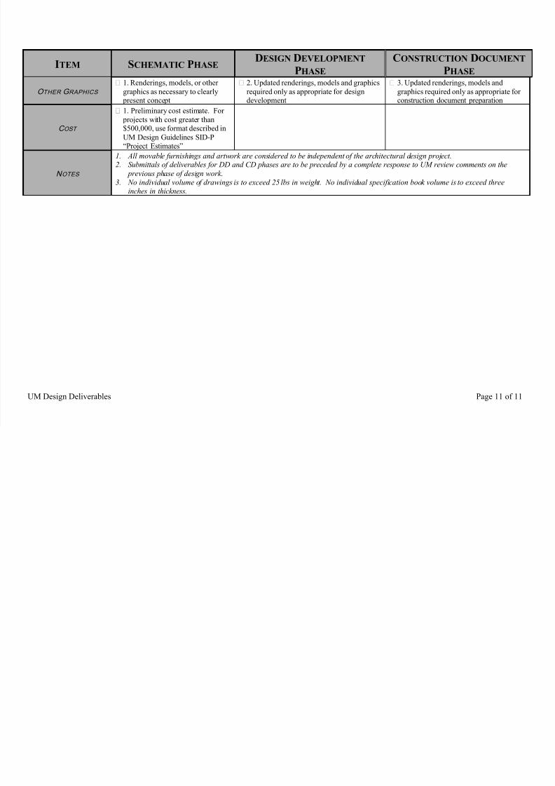
O THER G RAPHICS
1. Renderings, models, or othergraphics as necessary to clearly
present concept
2. Updated renderings, models and graphicsrequired only as appropriate for design
development
3. Updated renderings, models andgraphics required only as appropriate for
construction document preparation
C OST
1. Preliminary cost estimate. For projects with cost greater than$500,000, use format described inUM Design Guidelines SID-P“Project Estimates”
N OTES
1. All movable furnishings and artwork are considered to be independent of the architectural design project.2. Submittals of deliverables for DD and CD phases are to be preceded by a complete response to UM review comments on the
previous phase of design work.3. No individual volume of drawings is to exceed 25 lbs in weight. No individual specification book volume is to exceed three
inches in thickness.