Embed Size (px)
Citation preview
Design criteria and recent developments i-nlarge-capacity Wemco flotation cells
by P. KIND*, Ph.D. (Clausthal), B.Sc. (Visitor)
SYNOPSIS
The scaling-up of the large flotation cells that have been developed during the past few years has been based onhydrodynamic considerations and has resulted in a 500 ft3 cell unit. Plant results on a porphyry copper ore showthat the 500 ft3 unit is equivalent to the previously used 300 ft3 model.. .
Plant tests on the use of 300 ft3 flotation cells for the recovery of phosphate, particularly from the coarse sizefractions, are also described.
SAMEVATTING
Die skaalvergroting van die groot flottasieselle wat in die loop van die afgelope paar jaar ontwikkel is, is op hidro-dinamiese oorwegings gegrond en het gelei tot 'n seleenheid van 500 vt3. Aanlegresultate vir porfierkoperertshet getoon dat die eenheid van 500 vt3 gelyk staan met die model van 300 vt3 wat vroeer gebruik is.
Aanlegtoetse in verband met die gebruik van flottasieselle van 300 vt3 vir die herwinning van fosfaat, veral uitdie growwe groottefraksies, word ook beskryf.
INTRODUCTION
The Wemco flotation cell of todaystarted as the Fagergren flotationcell, which was invented in theearly 1930's by William Fagergrenin Utah, U.S.A. Up to 1948 it wasmarketed by Cyanamid, and sincethen by Wemco, now a Division ofEnvirotech Corporation, Menlo Park,California, U.S.A.
The Fagergren was characterizedby its deep multi-piece squirrel-cage rotor and squirrel-cage shroud.In 1967/1968, Wemco developed andpatented a new one-piece deep rotorand a one-piece stator (U.S. patent3,491,880), sold under the trademark 1+ 1. Fig. 1 shows the con-
conventional mechanism
~0
Im...~
('I +
b8...,03
..~
1 + 1 rotor.stator
mJr1 "I:
.
,.t.,
+
Fig. I-Wemco mechanisms
*Wemco Europe, Division of Envirotech,France.
ventional Fagergren impeller andthe 1+ 1 star rotor-disperser. Until1967, Wemco cell sizes ranged from1 to 60 £t3.
In 1967, the 300 ft3 cell wasdeveloped and successfully comparedin a parallel industrial test againstthe 60 ft3 cells. In 1970, the first500 ft3 cell (no. 144) was tested inthe flotation of iron ore in NorthAmerica.
PRINCIPLE
...t.,
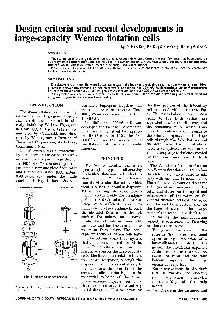
The Wemco flotation cell is anopen-trough type, self-aeratingmechanical flotation cell, which isshown in Fig. 2. The mechanismconsists of a star-like rotor, whichrotates inside the shroud or disperser.When operating, the rotor createsa fluid vortex inside the standpipeand in the draft tube, this vortexbeing at a sufficient vacuum toinduce air into the standpipe throughthe air inlet from above the cellsurface. The induced air is mixedinside the rotor-stator zone withthe pulp that has been sucked intothe rotor from below. The large-capacity Wemco flotation cells havea false-bottom draft-tube systemthat enhances the circulation of thepulp. It permits a low rotor sub-mergence, even for the large-capacitycells. The three-phase mixture leavesthe shroud (disperser) through thedisperser apertures in radial direct-ion. The new disperser fulfils theshrouding effect perfectly, since thetangential velocity of the three-phase mixture imparted on it bythe rotor is converted to an entirelyradial direction. This is shown by
JOURNAL OF THE SOUTH AFRICAN INSTITUTE OF MINING AND METALLURGY
the flow pattern of the laboratorycell, equipped with 1+ 1 parts (Fig.3). The particle-loaded air bubblesrising to the froth surface areseparated outside the disperser, andthe remaining pulp, which flowsdown the tank walls and returns tothe rotors, is separa,ted in the largecells through the false bottom andthe draft tube. The conical statorhood is to quieten the cell surfaceand to keep any turbulence createdby the rotor away from the frothlayer.
The function of the mechanismin a Wemco flotation cell is thereforethreefold: to circulate pulp, to mixpulp with air, and to draw in air.These functions depend on the shapeand geometric dimensions of therotor and stator, on the speed andsubmergence of the rotor, on thevertical distance between the rotorand the real tank bottom and, forthe large cell sizes, on the engage-ment of the rotor in the draft tube.
As far as the pulp-circulationcapacity is concerned, the followingrelations can be stated.
- The greater the speed of therotor tip (by increased rotationalspeed or by installation of alarger-diameter rotor), thegreater the circulation capacity.
- A decrease in the clearance be-tween the rotor and the tankbottom improves the pulp-circulation capacity.
- Rotor engagement in the drafttube is essential for effectivepulp circulation; otherwise,short-circuiting of the pulpoccurs.
- An increase in the tip speed and
MARCH 1976 345
,rWEIR LEVEL
"r")
'~ ,ROTOR
"ISU~~fRGENCE
.11. ;!' " I In: 1jJ "" :
I Ri;'. } -ROTOR TOP
!I i
/., 1 I: /'
..TUBE~r-yr L-"d--.J--r:"\ .' '-ADJUSTABLE COLLAR
'.,-u u- .. Lf-- .. --u.. ~j u { '-FALSE BOTTOM
AIR INLET DUCT~__--STAND PIPE: --! "-
--., "---(-
.HOODt
iDISPERSER
a. decrease in the distance be-tween the rotor and the tankbottom increases the power con-sumption.
Concerning aeration character-istics, the relations listed below canbe expected.
- The greater the speed of therotor tip, the greater the volumeof induced air.
- The lower the submergence ofthe rotor, the greater the volumeof induced air.
- The lower the specific gravity andthe viscosity of the flotationpulp, the greater the quantityof induced air.
Obviom::ly, an optimum conditionis to be found for the variousparameters mentioned above. Thisis particularly true for the flotation ofcoarse particles, where a greaterturbulence is required to keep thecoarser solids in suspension, butit is limited by the reduced stabilityof the particle/air-bubble unit, Fur-ther, large air bubbles would berequired.
SCALE-UP CONSIDERATION
When flotation cells are scaled upfrom a given size to larger units, the
346 MARCH 1976
i'"1-
4
(, MOTOR
I>.
_..~ :
I J'---+--'
~
Fig. 2-Wemco I+ I flotation cell
Fig. 3-Wemco laboratory cell with I+ I parts
JOURNAL OF THE SOUTH AFRICAN INSTITUTE OF MINING AND METALLURGY
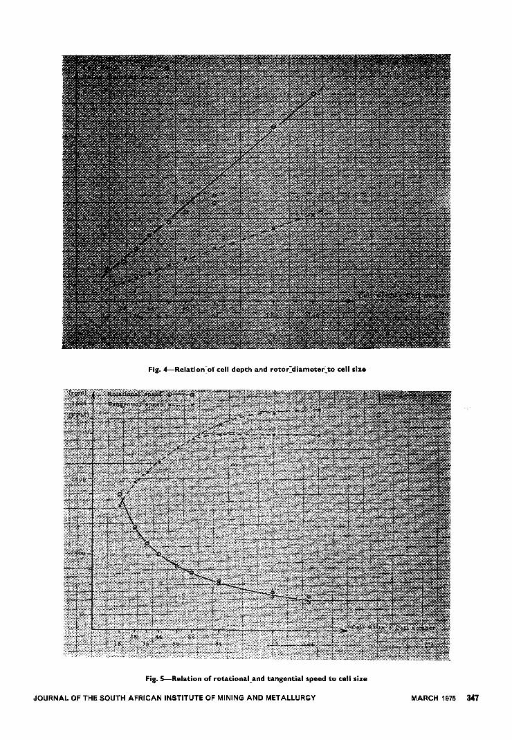
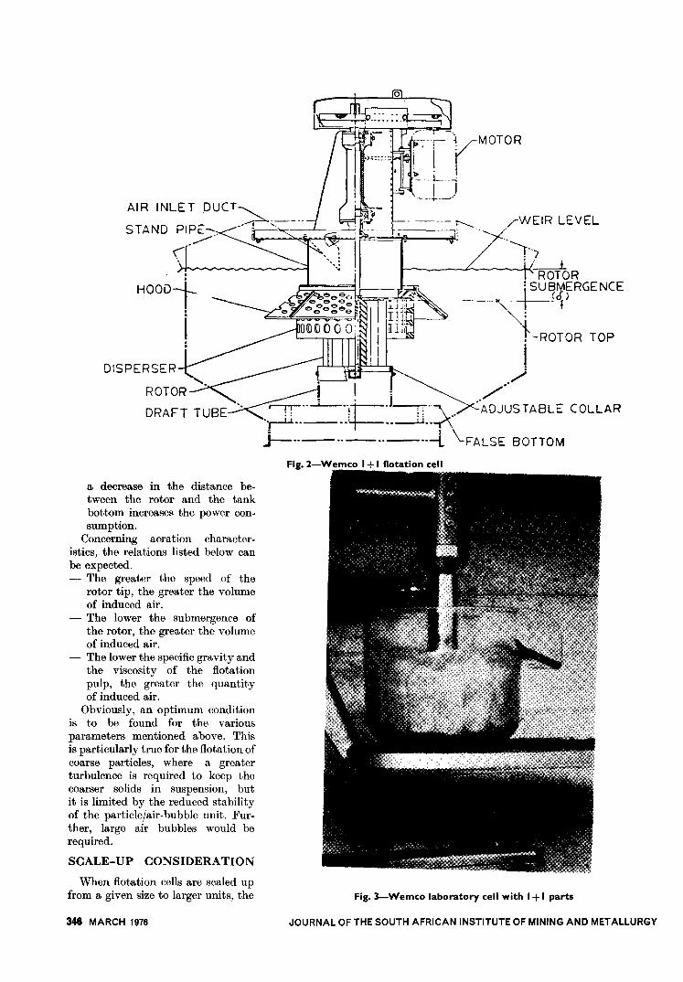
Fig. 4-Relation:of cell depth and roto(diamete(to cell size
Fig. 5-Relation of rotationa'-and tangential speed to cell size
JOURNAL OF THE SOUTH AFRICAN INSTITUTE OF MINING AND METALLURGY MARCH 1976 347
specific capacities of the mechanismswith regard to pulp circulation, airdispersion, and air induction mustbe maintained. Only if this is donecan one expect to process largequantities of a given raw materialin a larger cell with the samemetallurgical results.
If the width of the cell is regardedas a basic parameter of the celltank (also being the size number ofWemco flotation cells), the depth ofthe cell is scaled up in a linearway (Fig. 4). This means that abigger cell is also a deeper cell. Thelength of the tank, i.e., the distancebetween two mechanisms, can varybetween 75 and 100 per cent of thetank width, depending on the appli-cation. The ratio of blade height torotor diameter remains almost con-stant, with values of 1,14 and 1 forthe 1 ft3 and the 500 ft3 modelrespectively. As shown in Fig. 4,the diameter of the star rotorincreases linearly with the widthof the cell, which corresponds to aconstant ratio of impeller diameterto cell width.
Once the geometric parameters
348 MARCH 1976
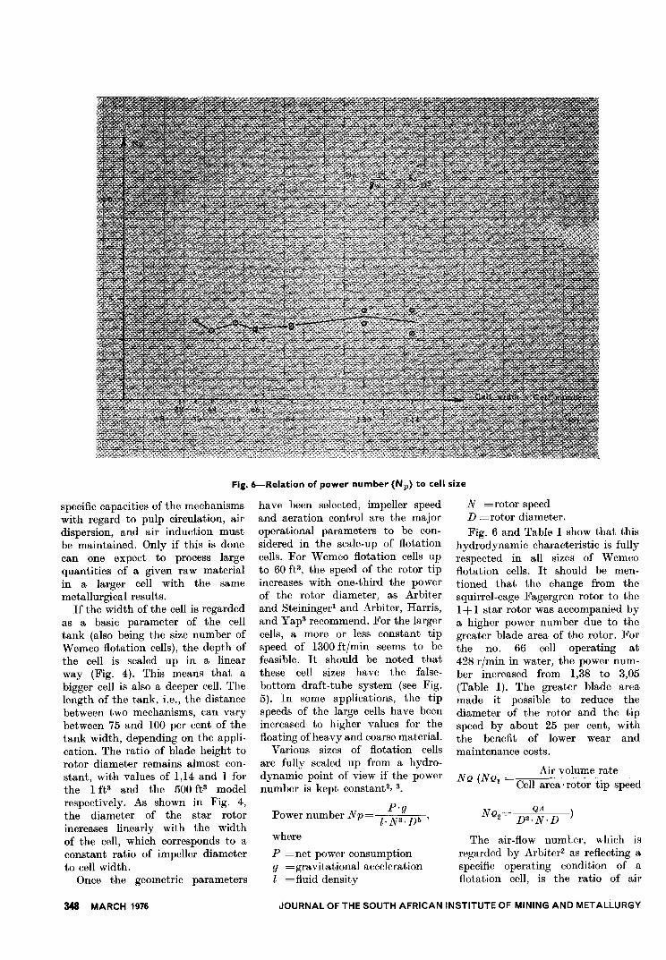
Fig. 6-Relation of power number (Np) to cell size
have been selected, impeller speedand aeration control are the majoroperational parameters to be con-sidered in the scale-up of flotationcells. For Wemco flotation cells upto 60 ft3, the speed of the rotor tipincreases with one-third the powerof the rotor diameter, as Arbiterand Steiningerl and Arbiter, Harris,and Yap3 recommend. ]'or the largercells, a more or less constant tipspeed of 1300 ft/min seems to befeasible. It should be noted thatthese cell sizes have the false-bottom draft-tube system (see Fig.5). In some applications, the tipspeeds of the large cells have beenincreased to higher values for thefloating of heavy and coarse material.
Various sizes of flotation cellsare fully scaled up from a hydro-dynamic point of view if the powernumber is kept constant2,3.
Power number NpP'g
l. N3. D5 'where
P =net power consumptiong =gravitational accelerationl =fluid density
N =rotor speedD =rotor diameter.Fig. 6 and Table I show that this
hydrodynamic characteristic is fullyrespected in all sizes of Wemcoflotation cells. It should be men-tioned that the change from thesquirrel-cage Fagergren rotor to the1+ 1 star rotor was accompanied bya higher power number due to thegreater blade area of the rotor. Forthe no. 66 cell operating at428 r/min in water, the power num-ber increased from 1,38 to 3,05(Table I). The greater blade areamade it possible to reduce thediameter of the rotor and the tipspeed by about 25 per cent, withthe benefit of lower wear andmaintenance costs.
NQ (NQlAir volume rate
Cell area' rotor tip speed
QANQ2-
D2.N.D
The air-flow numter, which isregarded by Arbiter2 as reflecting aspecific operating condition of aflotation cell, is the ratio of air
JOURNAL OF THE SOUTH AFRICAN INSTITUTE OF MINING AND METALLURGY
IN3 D" p* Pr/s3 ft" h.p. ft Ibis
865,52 0,06735 0,8 440,19578,01 0,177896 1,2 660,28343,00 0,648405 3,0 1650,72253,64 1,357270 4,2 2311,00137,39 7,5 4126,80159,22 4,208727 8,5 4677,04
52,73 17 9354,0872,51 20,692469 20 1l004,8031,86 24 13205,7652,73 47,675169 29 15956,96
362,63 1,357271 5,3 2916,27I
362,63 4,915 ! 4728
ImpellerSize D N N
ft r/min r/s
36 0,583 57244 0,708 50056 0,917 42066 1,063 38084 1,333 310-
325120 1,833 225-
250141 2,166 190-
225------
--1,0~166 1+ I 42866 conv. 1,375 428
QAQA* - QA
ft3/min D'ft/mill TT-N-D3
12,5 36,8 35,2 x 10-323 45,88 41,2544 52,32 43,3170 61,95 48,97
125 70,34 54,31140 78,79 57,93260
I
77,38 59,75310 92,26 64,1l400 85,26 65,83540 115,10 75,23 I
ImpellerSize D N TT.N-D
ft r/min ft/mill
36 0,583 572 104544 0,708 500 11l256 0,917 420 120866 1,063 380 126584 1,333 310- 1295
325 1360120 1,833 225- 1295
250 1439144 2,166 190- 1295
225 1530
ACell
Cell surfaceSize surface ft'
---36 36 X 36 944 44x 44 13,4456 56 X 56 21,7766 66 X 66 30,2584 84 X 84 49,00
120 120 X 90 75,00
144 144 X 108 108,00
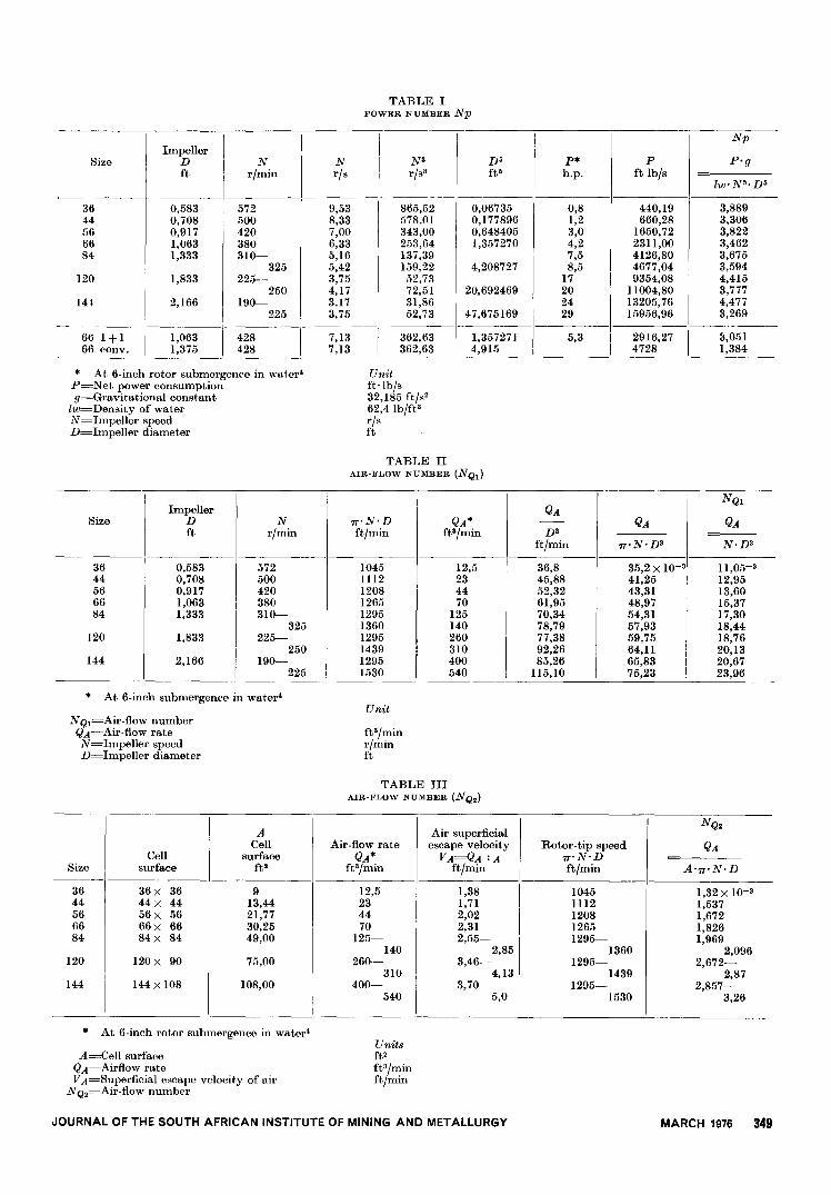
TABLE IPOWER NUMBER Np
9,538,337,006,335,165,423,754,173,173,75
1-~:~~
--
Np
P-g
lw- N3. D"----
3,8893,3063,8223,4623,6753,5944,4153,7774,4773,269.0_-
11,0511,384
* At 6-inch rotor submergence in water'P=Net power consumptiong=Gravitational constant
lw=Density of waterN=Impeller speedD=Impeller diameter
Unitft.lb/s32,185 ft/sa62,4 Ib/ft3r/sft
TABLE IlAIR-FLOW NUMBER (NQl)
NQl
QA
---N-D3
1l,05-312,9513,6015,3717,3018,4418,7620,1320,6723,96
* At 6-inch submergence in water'Unit
N Ql=Air-flow numberQA=Air-flow rateN=Impeller speedD=Impeller diameter
ft3/minr/minft
TABLE IIIAIR-FLOW NUMBER (N Q,)
I
Air superficialescape velocity
VA=QA :Aft/mill
1,381,712,022,312,55-
2,853,46-
4,133,70-
5,0
Rotor-tip speedTT-N.Dft/mill
10451112120812651295-
13601295-
14391295-
1530
NQ'
QAAir-flow rateQA*
ft3/min
12,5234470
125-140
260-310
400-540
*At 6-inch rotor submergence in water'
Unitsft'ft3/minft/mill
A=Cell surfaceQA=Airflow rateVA=Superficial escape velocity of air
NQ,=Air-flow number
JOURNAL OF THE SOUTH AFRICAN INSTITUTE OF MINING AND METALLURGY MARCH 1976
A-TT-N.D
1,32 X 10-31,5371,6721,8261,969
2,0962,672-
2,872,857-
3,26
349
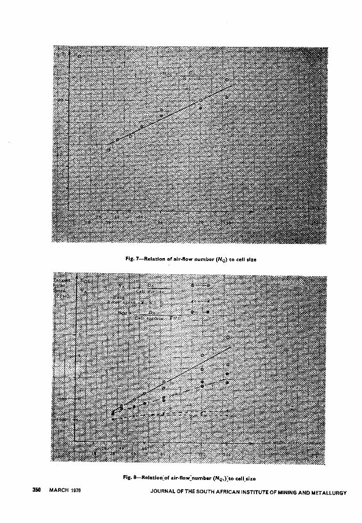
Fig. 7-Relation of air-flow number (NQ) to cell size
Fig. 8-Relation=of air-flow=number (NQ1»)O cell)ize
350 MARCH 1976 JOURNAL OF THE SOUTH AFRICAN INSTITUTE OF MINING AND METALLURGY
Rougher
Fine feed
Size Distn Cum.mesh % %(+)20 1,0 1,0
-20 +28 1,9 2,9-28 +35 7,6 10,5-35 +48 18,8 29,3-48 +65 27,1 56,4
(-)65 43,6 100,0
Solids in Phosphate (BPL*), % BPL*Feed rate feed recovery
ton/h % Feed Concentrate %
120 17 27,4 53,6 91,3170 22 26,0 58,7 88,2200 25 28,0 59,9 89,3200 25 21,7 51,9 87,1170 27 22,5 58,2 85,7
velocity (air volume rate to squareof impeller diameter, or air volumerate to cell surface) to the tangentialvelocity of the impeller. Tables 11and III and Figs. 7 and 8 show thevarious parameters.
The air-flow number increaseswith increasing cell size because theair velocity increases faster than thetangential speed of the rotor. Thisis related to the scale-up of thetank geometrics, which is character-ized by a linear scale-up of the celldepth. On the other hand, constantair intensity of the cell volume isrequired. In other words, at naturalaeration capacity, the air in ano. 120 cell would escape faster thanthat in a no. 66 cell.
Arbiter2 has shown with Balmatflotation that, only when the aerationis restricted, can plant results bereproduced in laboratory and pilotcells. From his investigation, it alsoappears that the same metallurgicalresults can be obtained in Wemcocells having the following air-flownumbers:
2-litre laboratory cell:NQ=I-2xlO-3
1 ft3 pilot cell:N Q=I,9-2,3 X 10⁻³
61 ft3 plant cell:N Q=2,7 X 10⁻³.
The magnitude of the N Q values ofArbiter's investigation and those inthe tables of this paper differ sincethe latter are related to the starrotor in water while the other data2are related to a squirrel-cage rotorin industrial flotation pulp.
RECENT DEVELOPMENTSAND TESTS
In spite of the recent progress inthe hydrodynamics of flotation-celldesign, major development workshould still be done in industrialplants. Wemco's work during thelast few years has been directed intwo distinct directions.
One was the development oflarge-capacity flotation cells, whichhas now resulted in the 500 ft3cell. It is obvious that lower primaryores need bigger installations, andconsequently larger equipment. Theneed for automatic operation of theseplants favours the trends towardsbigger units. The 500 ft3 cell witha daily unit capacity of up to 830 tjdof an average porphyry copper ore
is now being used in various plantsin North America. It should fulfilthe requirement of even the largestmill of today to accommodate onlyone flotation line to one grindingcircuit.
The other development wasdirected towards the use of large-capacity cells for the flotation ofcoarse particles, especially of phos-phates.
Flotation Tests at Brewster Plant
At the Haynsworth Mine atBradley, Florida, of the AmericanCyanamid Co., a nine-month testusing three no. 120 Wemco cells wascarried out to determine whetherlarge-capacity cells can be used toup-grade fine and coarse feed ofFlorida phosphate, about whichCustred, Degner, and LongS, 6 havereported.
Since the flotation feed in thesize range of 20 to 150 mesh is theundersize of the preceding up-grading steps such as washing,screening, cycloning, and hydraulicclassification, and since no crushingand milling steps are involved, theflotation feed is coarser than in most
other mineral applications. Theminus 150 mesh fraction is discardedas slimes, and the 20 to 150 meshfraction is classified by hydraulicsizers and vibrating screens into acoarse flotation feed (minus 20plus 35 mesh) and into a fineflotation feed (minus 35 plus 150mesh).
In the rougher flotation, thephosphate is floated separately inthe coarse and fine circuit, usingcrude fatty acid, fuel oil, andammonia for pH 9 to 9,5. Thetwo rougher froth products are thencombined, acid-washed, and sub-jected to a common cleaner circuit,where silica is floated with aminesand where the phosphate reports tothe cell underflow.
The tests were conducted forroughing only, both on the fine andcoarse feed. The test unit consistedof three no. 120 by 90 by 53 Wemcocells (300 ft3 unit cell volume) withdouble overflow and skimmers, andwith feed and discharge box andautomatic level control. Table IVsummarizes the size distribution ofthe fine and coarse feed, and Table Vgives the results of several months'
ROUGHER FLOTATION FEED" - SIZE DISTRIBUTION OF SOLIDS (% by mass - by screenfraction)
TABLE IV
circuit
Coarse feed
Distn%
Cum.
%4,28,6
15,928,926,915,5
4,212,828,757,684,5
100,0
*Rotor submergence=9 in
* Rotor speed=210 r/min
THREE-CELL ROUGHER FLOTATION CIRCUIT" - PERFORMANCE ON FINE FEED (Operatingcondition A)
TABLE V
JOURNAL OFTHE SOUTH AFRICAN INSTITUTE OF MINING AND METALLURGY
* Bone phosphate of lime
MARCH 1976 351
Rotor
I
Operating (top) Rotor Feed Solids in Phosphate (BPL*), % Phosphatecondition submergence speed rate feed
I
recoverym r/min ton/h % Feed Concentrate %
---A 9 210 120 20 26,4 58,1 85,9Bt 9 210 120 20 31,0 56,0 90,4C 13 210 120 20 27,8 56,8 87,8D 13 235 120 20 33,0 64,3 88,7D 13 235 180 25 30,2 62,9 88,3
TABLE VI
THREE-CELL ROUGHER FLOTATION CIRCUIT" - PERFORMANCE ON COARSE FEED
* Bone phosphate of lime
t False-bottom modification(See text for details)
operation on the fine feed at210 r/min (1208 ft/min, 6,14 m/s) anda rotor submergence of 9 inches. Thefeed rate was varied between 120and 200 ton/h and the solids con-centration between 17 and 27 percent by mass.
The metallurgical results achievedin the test unit on fine feed were thesame as obtained in the air cellsoperating in this plant. However,it was possible to increase the solidsconcentration to 27 per cent in thefeed, whereas it had up to thenbeen 17 per cent solids.
The test results obtained on thecoarse feed are shown in Table VI.In the first test scries on the coarsefeed, the operating conditions (A)were the same as for the fine feed.The result was that the same gradeof concentrate as in the plant couldbe obtained, but that the recoverycould not be achieved (85,9 percent for the test unit, 88,5 per centfor the plant). The 300 ft3 cellscould therefore not duplicate theplant results under standard opera-ting conditions, although the condi-tions were sufficient to give goodresults on the fine feed.
In order to improve the recoveryon the coarse feed, the test cellswere modified by covering the gapbetween the false bottom of twoadjacent cells with a plate called a'false-bottom extension plate'. Thismodification resulted in a continuousfalse bottom for the three cells andis referred to as operating conditionB. The test results show an improve-ment in recovery, most likely be-cause of better circulation of thepulp and better suspension of thecoarse material. However, the gradeof the concentrate was lower.
Then, in order to improve thegrade of the concentrate, the entire
352 MARCH 1976
mechanisms were lowered by 4inches, and the rotor submergencewas consequently increased from9 to 13 inches. This modificationresulted in an improved grade ofconcentrate but lower recovery. Thelast modification was to increasethe rotor speed from 210 to 235 r/min(1208 to 1352 f/min or 6,14 to6,87 m/s), which brought the re-covery to the plant value (88,5per cent) while the grade of theconcentrate of the test cells wasthe same or up to 3 per cent higherthan that of the plant cells. Further-more, the throughput could beincreased without any major lossin grade and recovery by 50 percent to 180 ton/h.
A final test consisted of feedingthe fine feed into the test unit andoperating at 235 r/min with thelowered mechanism and the con-tinuous false-bottom. At a feedrate of 200 ton/h, 30 per centsolids, and 24,4 per cent phosphatein the feed, a concentrate of 58,6p~r cent bone phosphate of lime(BPL) at a recovery of 86,2 percent was obtained.
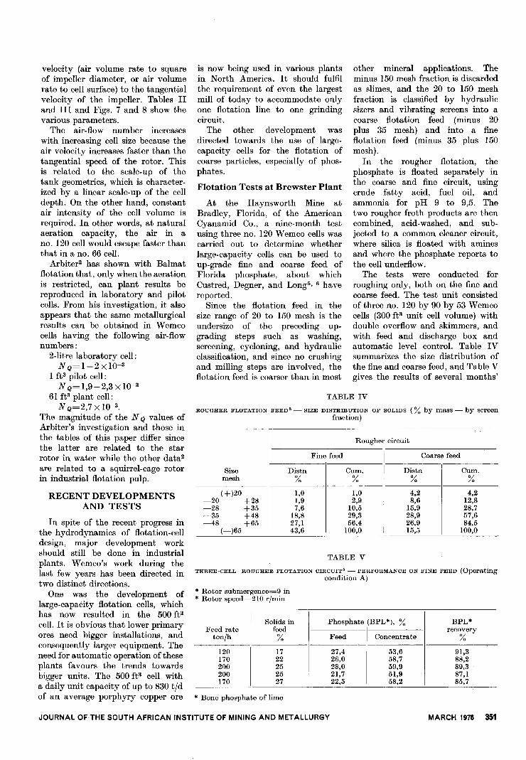
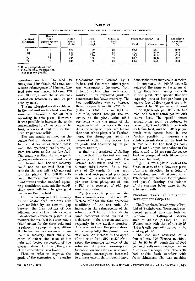
Fig. 9 shows the power and air-flow characteristics of the no. 120Wemco ce1l5 for the four operatingconditiom of the test unit. Anincrease in the submergence of therotor from 9 to 13 inches at thesame rotational speed resulted ina decrease in the aeration and con-sequently in the air-flow number.At the same time, the power draw,and consequently the power inten-sity, rose. An increase in the speedof the rotor from 210 to 235 r/minraised the pumping capacity of therotor and the power commmption.Since the aeration rate also increased,the power consumption increasedto a lesser extent than it would have
done without an increase in aeration.In summary, the 300 ft3 test cells
achieved the same or better metal-lurgy than the existing air cellsin the plant. The specific flotationcapacity (tons of feed per hour persquare foot of floor space) could beincreased by 50 per cent. It wentup to 0,65 ton/h per ft2 with finefeed, and to 0,59 ton/h per ft2 withcoarse feed. The specific powerconsumption could be reduced tobetween 0,27 and 0,36 h.p. per ton/hwith fine feed, and to 0,42 h.p. perton/h with coarse feed. It wasfurther possible to increase thesolids concentration in the feed to30 per cent for fine feed (as com-pared with 18 per cent solids in theplant), and to 25 per cent for coarsefeed (as compared with 16 per centsolids in the plant).
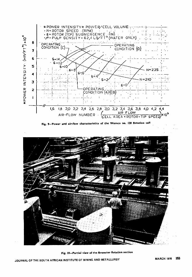
Fig. 10 shows a partial view of theflotation area of the Brewster plantafter recomtruction. In a total oftwenty-four no. 120 Wemco cells,1260 ton/h are treated for roughingand partial cleaning, the balanceof the cleaning being done in theexisting air cells.
Flotation Tests at PhosphateDevelopment Corp. Ltd
The Phosphate Development Corp.Ltd of Phalaborwa, Transvaal, con-ducted parallel flotation tests tocompare the metallurgical perform-ance of 300 ft3 (8,4 m3) no. 120Wemco cells with that of the 50 ft3(1,4 m3) cells currently in use in theexisting planV.
The test unit consisted of afour-cell no. 120 Wemco machine,120 by 90 by 53, consisting of feedbox - 2 cells - connection box-2 cells - discharge box. The cellshad double froth overflow withfroth skimmers. The test machine
JOURNAL OF THE SOUTH AFRICAN INSTITUTE OF MINING AND METALLURGY
..Q
"* POWER INTENSITYe POWEFVCEL~-VOLUME-;--:-'--:--'--+-"' :-oN=ROTORSPEED-(RPM)
, .,; ; ,:: ,;: :-:_-
o~=ROTOR(TOP) SUBMERGENCE .(IN} , -:-' :_-~- - :,_~_L,o.
'P=P~LP DENSITY=,62,4 LEVFT3(W~TER ONLY) . ,;- :" .~
,:.
-HOPERATrNG---u_L'_H_-_h__:_-"_H" '-"'~"_:'-' - 0-- -- .-- : --_:, --,--- '.
CONDITION (C) " ; .-'
.OPERATING:- --':-'---:-.-'
-' CONDITION (DJ:. - w' . 0..
x 8.......181r-LL~I-
7
6
>- 5
~=14. S=12
&=10- 0"
,,:6=8 N=2J-S -T-
.
;' - -- -.. --:"""'--- . -- ;--~--
.. ..
:....(j)
ZWr-Z
0::w~0Q...
~ -, .h___,__-,--- -, .., :. - - - ,------&=4
, ,,-
,- : 5=2 ..':. ..~: ,.:.u, ',:~:::1.- :'6-='0', -, ,~-~-:
-:~".-;-"
OPERATlNG'_': : : -:,~- ::',::,
,F~NDITION (A)f(8r~--:':-~---j~:~-:-r--~~'
,L--:<_i. -\ ,-3 ._-:-:-_:_-::- -,- '::":n~+h:--"-
-,
, ,-
2 : -: I' - - 0,-- - ---n -_u--,
I: :. ---I-: : -
-"
...- --- I
- - '.. - - .' j"'---'--
,
" 1,6 1,8 2,0 2,2 2,4 2,6 2,8 3,0 3,2 3,4 3,6 3,8 4,0 4)2 4.4
AIR-FLOW NUMBER -, f.. AIR FLOW '\ s\CELL AREA x ROTOR-TIP SPEE:DjXIO
Fig. 9-Power and air-flow characteristics of the Wemco no. 120 flotation cell
Fig. IO-Partial view of the Brewster flotation section
JOURNAL OF THE SOUTH AFRICAN INSTITUTE OF MINING AND METALLURGYMARCH 1976 353
Four 300 ft' Wemco ce
Condition of four p.~., %Test 300 ft'no. Wemco cells Feed Conc. Tail.
2F Standard no. 120 rotor, 14,7 25,7 8,7220 r/min, 1300 flmin,9 in rotor submergence
3F No. 144 A rotor, 220 17,6 29,2 10,7rlmin, 1500 flmin, 131 inrotor submergence
6F As in 3F plus additional 12,4 24,9 6,4small-hole diffuserc linder
Two rows 0 1250 t ce s 1 erencein recovery
p.~., % p.~. 300 ft'I recovered cells-50
Feed Conc. Tail. % ft' cells
14,7 26,6 7,4 68,8 -7,1
17,6 28,7 10,5 63,6 -1,7
12,3 23,9 6,7 63,6 +1,5
I
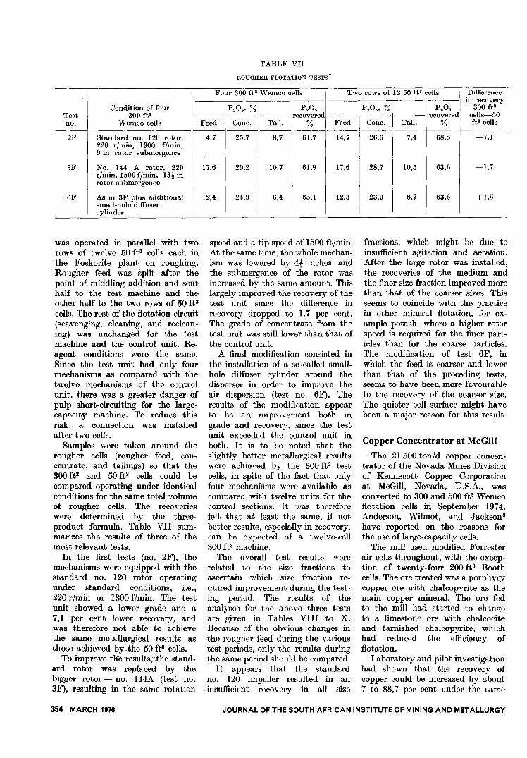
TABLE VII
ROUGHER FLOTATION TESTS?
y
lls
p.~.recovered
%61,7
61,9
65,1
f f 3 D'ffiII
was operated in parallel with tworows of twelve 50 ft3 cells each inthe Foskorite plant on roughing.Rougher feed was split after thepoint of middling addition and senthalf to the test machine and theother half to the two rows of 50 ft3cells. The rest of the flotation circuit(scavenging, cleaning, and reclean-ing) was unchanged for the testmachine and the control unit. Re-agent conditions were the same.Since the test unit had only fourmechanisms as compared with thetwelve mechanisms of the controlunit, there was a greater danger ofpulp short-circuiting for the large-capacity machine. To reduce thisrisk, a connection was installedafter two cells.
Samples were taken around therougher cells (rougher feed, con-centrate, and tailings) so that the300 ft3 and 50 ft3 cells could becompared operating under identicalconditions for the same total volumeof rougher cells. The recoverieswere determined by the three-product formula. Table VII sum-marizes the results of three of themost relevant tests.
In the first tests (no. 2F), themechanisms were equipped with thestandard no. 120 rotor operatingunder standard conditions, i.e.,220 r/min or 1300 f/min. The testunit showed a lower grade and a7,1 per cent lower recovery, andwas therefore not able to achievethe same metallurgical results asthose achieved by,. the 50 ft3 cells.
To improve the results; the stand-ard rotor was replaced by thebigger rotor - no. 144A (test no.3F), resulting in the same rotation
354 MARCH 1976
speed and a tip speed of 1500 ft/min.At the same time, the whole mechan-ism was lowered by 4t inches andthe submergence of the rotor wasincreased by the same amount. Thislargely improved the recovery of thetest unit since the difference inrecovery dropped to 1,7 per cent.The grade of concentrate from thetest unit was still lower than that ofthe control unit.
A final modification consisted inthe installation of a so-called small-hole diffuser cylinder around thedisperser in order to improve theair dispersion (test no. 6F). Theresults of the modification appearto be an improvement both ingrade and recovery, since the testunit exceeded the control unit inboth. It is to be noted that theslightly better metallurgical resultswere achieved by the 300 ft3 testcells, in spite of the fact that onlyfour mechanisms were available ascompared with twelve units for thecontrol sections. It was thereforefelt that at least the same, if notbetter results, especially in recovery,can be expected of a twelve-cell300 ft3 machine.
The overall test results wererelated to the size fractions toascertain which size fraction re-quired improvement during the test-ing period. The results of theanalyses for the above three testsare given in Tables VIII to X.Because of the obvious changes inthe rougher feed during the varioustest periods, only the results duringthe same period should be compared.
It appears that the standardno. 120 impeller resulted in aninsufficient recovery in all size
fractions, which might be due toinsufficient agitation and aeration.After the large rotor was installed,the recoveries of the medium andthe finer size fraction improved morethan that of the coarser sizes. Thisseems to coincide with the practicein other mineral flotation, for ex-ample potash, where a higher rotorspeed is required for the finer part-icles than for the coarse particles.The modification of test 6F, inwhich the feed is coarser and lowerthan that of the preceding tests,seems to have been more favourableto the recovery of the coarser size.The quieter cell surface might havebeen a major reason for this result.
Copper Concentrator at McGill
The 21 500 ton/d copper concen-trator of the Nevada Mines Divisionof Kennecott Copper Corporationat McGill, Nevada, D.S.A., wasconverted to 300 and 500 ft3 Wemcoflotation cells in September 1974.Anderson, Wilmot, and Jackson8have reported on the reasons forthe use of large-capacity cells.
The mill used modified Forresterair cells throughout, with the excep-tion of twenty-four 200 ft3 Boothcells. The ore treated was a porphyrycopper ore with chalcopyrite as themain copper mineral. The ore fedto the mill had started to changeto a limestone ore with chalcociteand tarnished chalcopyrite, whichhad reduced the efficiency offlotation.
Laboratory and pilot investigationhad shown that the recovery ofcopper could be increased by about7 to 88,7 per cent under the same
JOURNAL OF THE SOUTH AFRICAN INSTITUTE OF MINING AND METALLURGY

+48 28,2
I
13,5448-100 16,8 21,58
100-200 14,1 20,29200-400 12,7 11,87
-400 28,2 9,9
otal (assay)' 100,0 14,7
tal (recalco)1 (14,6)
12,8 37,88 37,718,0 39,20 17,016,0 34,78 12,913,4 19,06 10,139,8 17,20 22,3
100,0 26,6 100,0
(26,9)
' 9,60 38,9710,62 69,64
7,32 80,954,02 83,805,4 66,24
7,4 68,8
(7,98)
Feed, %
Mass p.O.
23,1 15,419,7 23,714,5 23,611,9 17,330,8 13,6
100,0 17,6
(17,89)
Difference inp.O. recovery 300
recovery fta-50 ftaMass p.O. % cells
28,1 11,5 35,2 -0,618,4 15,2 58,2 -6,813,2 11,9 73,1 -2,310,1 7,4 78,9 -3,030,2 8,6 65,2 -2,4
100,0 10,7 61,9 -1,7
(10,94)
11,5 35,813,7 65,011,6 75,4
7,6 81,98,8 67,6
10,5 63,6
(10,89)
--Mass p.O.
-----11,5 38,921,2 39,617,3 37,014,6 26,935,4 19,7
100,0 29,2
(30,17)
23,1 15,4 0,7 39,4 31,119,7 23,7 21,0 39,0 20,214,5 23,6 18,2 35,6 13,211,9 17,3 16,1 24,1 9,330,8 13,6 35,0 18,4 26,2
100,0 17,60 100,0 28,7 100,0
(17,89) (28,81)
TABLE XROUGHER FLOTATION - TEST 6F1
I
Difference inFeed, % Concentrate, % Tailings, % p.o. recovery 300
--- recovery fta-50 ftaMesh
IMass p.O. Mass p.O. Mass p.O. % cells
+48 28,8 10,70 11,9 35,81 32,9 6,68 46,18 + 13,9148-100 19,9 15,49 21,5 34,84 19,2 7,46 65,94 + 4,98
100-200 18,7 14,61 22,3 25,26 14,1 8,15 65,26I
-10,00200-400 11,3 12,95 16,3 19,37 18,8 5,35 81,06 - 4,90
-400 21,3 10,6 28,0 15,90 15,0 5,9 70,5 -05,18---
Total (assay) 100,0 12,4 100,0 24,9 100,0 6,4 65,1 + 1,5
Total (recalco)] (12,62) (24,99) (6,67)
50 fta cells
+48 28,8 10,40 8,6 38,27 34,948-100 20,6 15,61 18,0 35,79 21,7
100-200 17,5 14,25 22,2 26,23 15,9200-400 10,2 13,37 16,6 19,71 8,1
-400 22,9 10,6 34,6 15,9 19,4
Total (assay)I
100,0 12,3 100,0 23,9 100,0
Total (recalc.)1 (12,49) (24,33)
JOURNAL OF THE SOUTH AFRICAN INSTITUTE OF MINING AND METALLURGY
7,72 32,278,30 60,965,96 75,264,50 85,965,2 75,68
6,7 63,6
(6,82) i ..
300 fta cells
Feed, % Tailings, %Difference inrecovery 300
fta-50 ftacellsMeah
+4848-100
100-200200-400
-400---Total (assay)
Total (recalc.),
Mass p.O.
TABLE VIIIROUGHER FLOTATION - TEST 2F1
Concentrate, %
Mass I P.0. Mass
25,717,014,113,429,8
13,722,119,512,310,1
14,7
10,515,414,312,547,3
38,638,933,920,816,6
33,615,013,312,126,0
100,0
(14,69)
100,0I,
257
I (25:35)
100,0
5:) fta cells
(8,83)
T
To
p.O.
p.o.recovery
%9,8
13,09,85,26,4
38,1461,8369,9576,9559,61
- 0,83- 7,81-11,00- 6,85
- 6,63
8,7 61,70 - 7,1
300 fta cells
Meah
+4848-100
100-200200-400
-400
Total (assay)
I
Total (recalco)
50 fta cells
+48
I
48-100100-200200-400
-400
Total (assay)
Total (recalco)
300 fta cells
TABLE IXROUGHER FLOTATION - TEST 3F1
Concentrate, % Tailings, %
MARCH 1976 355
-- - --I
2750 2750 220000,988 0,988 0,9880,305 0,239 0,30024,640 23,420 21,63069,1 75,8 69,632,8 31,6 32,036,2 37,9 N/At
37,549 41,190 N/A
3,641
TEST ROW300 FT3 CELLS
Flotation Feed
~;eetions 5 - 6
WFinalCone.
2nd Scavenger
Final'TAi 1
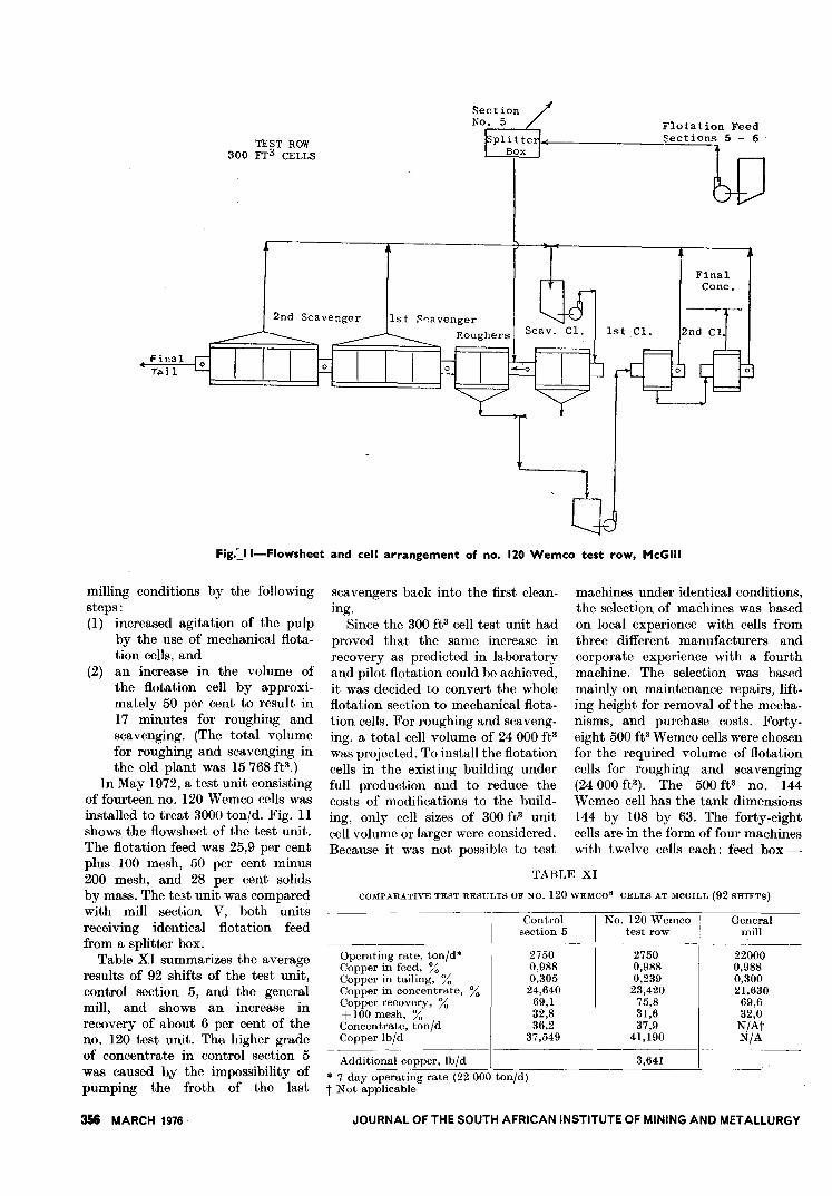
Fig.::"II-Flowsheet and cell arrangement of no. 120 Wemco test row, McGiII
milling conditions by the followingsteps:(1) increased agitation of the pulp
by the use of mechanical flota-tion cells, and
(2) an increase in the volume ofthe flotation cell by approxi-mately 50 per cent to result in17 minutes for roughing andscavenging. (The total volumefor roughing and scavenging inthe old plant was 15768 fP.)
In May 1972, a test unit consistingof fourteen no. 120 Wemco cells wasinstalled to treat 3000 ton/d. Fig. IIshows the flowsheet of the test unit.The flotation feed was 25,9 per centplus 100 mesh, 50 per cent minus200 mesh, and 28 per cent solidsby mass. The te3t unit was comparedwith mill section V, both unitsreceiving identical flotation feedfrom a splitter box.
Table XI summarizes the averageresults of 92 shifts of the test unit,control section 5, and the generalmill, and shows an increase inrecovery of about 6 per cent of theno. 120 test unit. The higher gradeof concentrate in control section 5was caused b.y the impossibility ofpumping the froth of the last
356 MARCH 1976
scavengers back into the first clean-ing.
Since the 300 ft3 cell test unit hadproved that the same increase inrecovery as predicted in laboratoryand pilot flotation could be achieved,it was decided to convert the wholeflotation section to mechanical flota-tion cells. For roughing and scaveng-ing, a total cell volume of 24 000 it3was projected. To install the flotationcells in the existing building underfull production and to reduce thecosts of modifications to the build-ing, only cell sizes of 300 ft3 unitcell volume or larger were considered.Because it was not possible to test
machines under identical conditions,the selection of machines was basedon local experience with cells fromthree different manufacturers andcorporate experience with a fourthmachine. The selection was basedmainly on maintenance repairs, lift-ing height for removal of the mecha-nisms, and purchase costs. Forty-eight 500 it3 Wemco cells were chosenfor the required volume of flotationcells for roughing and scavenging(24000 it3). The 500 ft3 no. 144Wemco cell has the tank dimensions144 by 108 by 63. The forty-eightcells are in the form of four machineswith twelve cells each: feed box-
TABLE XI
Controlsection 5
COMPARATIVE TEST RESULTS OF NO. 120WEMCO. CELLS AT MC GILL (92 SHIFTS)
Generalmill_J I
No. 120 Wemco
I
test row- --
Operating rate, ton/d*Copper in feed, %Copper in tailing, %Copper in concentrate, %Copper recovery, %+ 100 mesh, %Concentrate, ton/dCopper Ib/d
----Additional copper, Ib/d
* 7 day operating rate (22 000 ton/d)t Not applicable
JOURNAL OF THE SOUTH AFRICAN INSTITUTE OF MINING AND METALLURGY
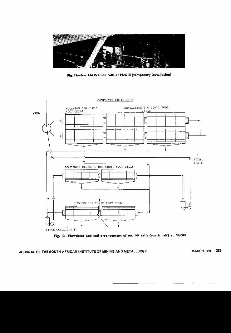
Fig. 12-No. 144 Wemco cells at McGiII (temporary installation)
COMPLETED SOUTH R~LF
FEED
ROUGHERS 500 CUBICFOOT CELLS
SCAvLNGERS 500 CUBIC FOOTCELLS
"0
FINAL
TAILS
SCAvLNGER CLEA~~RS 200 CUBIC FOOT CELLS
0
0 ~\ I
~
CMCLEANER 300 cv IC FOOT CELLS
FINAL CONCENTRATE
Fig. I3-Flowsheet and cell arrangement of no. 144 cells (south half) at McGiII
JOURNAL OF THE SOUTH AFRICAN INSTITUTE OF MINING AND METALLURGY MARCH 1976 357
0,594 0,5940,04 0,04
16,39 14,030,58 0,4816,9 21,0
0,108 0,14635,5 35,9
82,4 76,241,0 40,1
TABLE XII
COMPARATIVE RESULTS OF NO. 144 WEMCO8 - CELL SECTION AND FORRELTER AIR-CELL
SECTION
North half of plantForrester air cells
HeadCopper, %Insoluble copper, %
ConcentrateCopper, %MoS., %Insolubles, %
TailingCopper, %+ 100 mesh, %
RecoveryCopper, %MoS., %
4 cells - connection box - 4 cells -connection box - 4 cells - dis-charge box.
Fig. 12 shows no. 144 Wemco cellson a temporary installation duringthe construction period. Fig. 13shows the flowsheet and cell arrange-ment for one half of the new flotationplant. The rougher concentrate iscleaned twice in open circuits offour 300 ft3 cells each. The scavengerconcentrate is cleaned in eight200 ft3 cells and is then subjectedto the same two-stage cleaning a'!the rougher concentrate.
As shown in Fig. 13, the twoparallel rows have one commoncentral froth launder 3 ft wide andone outer launder 2 ft wide with adepth of from 4 to 8 ft. The walk-ways are above the cell surface andthe froth launder, and permit asubstantial saving in floor space.All cells have slide-gate air controlto throttle air back both for the300 and the 500 ft3 cells.
Table XII compares the results ofthe completed half of the plantwith the old half of the plant. Theseresults confirm the findings of theno. 120 300 ft3 test row, i.e., animprovement in the recovery ofcopper by about 6 per cent andin the grade of concentrate by about2 per cent.
Hydrometallurgy
A recent development is the pos-sible use of flotation machines inthe field of hydrometallurgy. Theleach reactors used in Anaconda'sArbiter process at Anaconda, Mon-tana, for the ammonium leachingof copper concentrate will be equip-ped with Wemco no. 144 mechan-
358 MARCH 1976
South half of plantNo. 144 Wemco cells
isms. More details are expected tobe reported elsewhere at a laterdate.
CONCLUSIONS
The following conclusions canbe drawn.1. The plant results now available
indicate that the metallurgyand specific flotation capacity ona porphyry copper ore are thesame for the 500 ft3 Wemcono. 144 flotation cell as for the300 ft3 Wemco no. 120 flotationcell. Other units of the 500 ft3size are in operation in NorthAmerica on the flotation ofiron ore (reverse silica float). Itmight be expected that 500 ft3will soon be the favourite cellsize for roughing and scavengingin new large-capacity concen-trators. The 300 ft3 model mightbe used more exten'!ively as acleaner in future big mills.
2. It has become possible to floatcoarse phosphate in 300 ft3 cellsby modification of the standardcell. In one case, the designimpeller speed was increasedby 10 per cent; in anothercase, a higher tip speed wasachieved by the use of anoversize impeller. In both cases,the submergence of the rotorwas increased. The3e resultsmight be of interest to flotationplants with modern grinding-cyclone circuits. In cases of diffi-culties with classification whenthe grinding-mill product isdischarged direct into the flota-tion cell, the increased suspen-sion capacity of the loweredmechanism could help to trans-
3.
port this eoarse materialthrough the flotation cell. Itis to be noted that the rotor stilloperates above the cell bottomand above the trash material.Dangerous rotor impacts arestill avoided, and this is furtherfacilitated by the flexible, all-polymer 1+1 rotor-stator,which has no metallic core.The example of the McGillcopper concentrator, where thewalkways are installed abovethe froth launders, might be ofgeneral interest in the saving offloor space.To avoid the manual operationof flotation machines, there is,at least in North America, anincreased tendency to equipboth dart valves of flotationcells with automatic level con-trols. When there is a powerfailure, the level controls auto-matically shut off the celldischarge and avoid emptyingof the flotation cells.
4.
ACKNOWLEDGEMENTS
The author wishes to thank theBrewster Phosphate Company, theKennecott Copper Corporation, theNevada Mines Division, and thePhosphate Development CorporationLtd for permission to use materialfor this paper.
REFERENCESl. ARBITER, N., and STEININGER, J.
Hydrodynamiques des machines deflottation. Congres de Cannes, 40J.
2. ARBITER, N., and WEISS, N. L.Design of flotation ce~ls and circuits.8ME preprint 70-B-89.
3. ARBITER, N., HARRIS, C. C., andYAP, R. F. A hydrodynamic approachto flotation scale-up. Paper D-19, 8thInternational Mineral Processing Con-gress, Leningrad, 1968.
4. DEGNER, V. R. Internal CompanyReports. Final Report R-73-004-Wemco (I + I) mechanism air transferand rotor power. 23rd Aug., 1973.
5. CUSTRED, U. K., DEGNER, V. R., andLONG, E. W. Recent advances incoarse particle recovery utilizing largecapacity flotation machines. S.M.E.Fall Meeting. 22nd-25th Sep., 1974.Acapulco, Mexico.
6. Wemco on the job. G981-16.7. PHOSPHATE DEVELOPMENT CORPORA-
TION LTD. Phalaborwa, Transvaal.Research Dept., Research report no. 83.
8. ANDERSON, M. A., WILMOT, C. I.,and JACKSON, C. E. A concentratorimproveme.n.t .and modernisation pro-gramme utIlIzIng large-volume flotationmachines. S.M.E. Upper PenninsulaSection, Houghton, Michigan, V.S.A.3rd May, 1974.
9. Wemco on the job. G881-25.
JOURNAL OF THE SOUTH AFRICAN INSTITUTE OF MINING AND METALLURGY
Discussion of the above paperD. A. Ireland*
The design of the Impala Concen-trator incorporates sixteen identicalrun-of-mine milling units in parallel,each with its own independentflotation circuit. The flow in all theflotation circuits is identical, con-sisting simply of roughing andcleaning. However, in the firstfour units installed, the roughersections each consist of three parallelbanks of 16 Wemco no. 66 cellswhilst, from No. 5 unit onwards, asingle row of ten no. 120 roughercells was installed for each unit. Inall other respects the circuits are thesame. The roughing is followed bycleaning in no. 44 cells.
Initially, the no. 66 units wereall equipped with squirrel-cage mech-anisms, but these have now largelybeen replaced with 1+ 1 mechanisms.
This design of independent parallelflotation circuits is obviously wellsuited to the testing of reagents,circuits, and cell performance sinceclassical statistical methods of com-parison are easily applied.
As soon as the first circuit wasinstalled with the no. 120 roughers,comparative tests were made of theseunits with and without froth skim-mers, and against the no. 66 cellswith squirrel-cage mechanisms andwith 1+ 1 mechanisms.
A study of the metallurgicalresults obtained on Impala orerevealed that there was no statisticaldifference in flotation performance
(i) between the no. 66 cells equip-ped with squirrel-cage and 1+1mechanism,
(ii) between the no. 120 cells withand without froth skimmers,and
(iii) between the no. 120 and theno. 66 cells.
It was found that the larger cellsconsumed 25 per cent less powerper unit cell volume than the no.66 cells with 1+ 1 mechanisms whilstgiving essentially the same metal-lurgical results. Experience hasshown that fewer man hours arerequired in the maintenance andoperation of the larger cells.
Dr Kind has pointed out and
*Impala Platinum Limited.
clearly shown from the results oftests that an optimum conditionis to be found for the various para-meters he has mentioned. He hasalso said that, despite the recentprogress in the field of hydro-dynamics in the design of flotationcells, the major development workmust still be done in industrialplants. I must agree with him onthis and I am certain that thereis still much to be gained by suchdevelopment and optimization.
My thanks are due to theManaging Director of Impala Platin-um Limited for permission to makethis contribution.
R. J. Adcockt
The use of extremely coarsegrinds and the presence of materialsof high specific gravity such asmagnetite, which are both conduciveto settlement at the bottom of thetank, has led to research work byWemco in the D.S.A. as well as byFraser & Chalmers Equipment inSouth Africa. Coarse grinds in thisinstance are defined as those havingless than 40 per cent minus 200 meshin the flotation feed. Examples ofthis are the 32 to 35 per cent minus200 mesh feed of a copper plant inArizona at which modifications tothe tank were carried out, and agrind of 35 to 40 per cent minus 200mesh at Palabora Mining Company,at which rotor dimensions werealtered.
Research work has centred roundchange in the design characteristicsof the rotor dimensions and theshape of the tank bottom.
Dimensional Changes in the Rotor
At the Palabora Mining Company,where the coarse feed is furtheraggravated by the high percentageof magnetite, and hence wheresanding problems have occurred,it was felt necessary to lengthen therotor so that the suction of the rotorwould penetrate deeper into thesand bed. The dimensions of therotor in use were 660 mm diameterand 470 mm length. The rotor
--tFraser & Chalmers Equipment (Pty)Limited.
JOURNAL OF THE SOUTH AFRICAN INSTITUTE OF MINING AND METALLURGY
rotated at a speed of 220 r/min,which is equivalent to 7,6 m/soThis-sized rotor was unsatisfactoryand had the following detrimentaleffects on the flotation cell.(a) A sand bed formed and covered
the false bottom, preventingcirculation of the pulp.
(b) Because of the sand bed, high-density layers at the base of therotor caused high wear at thispoint, leading to short rotorlife.
(c) Because of inefficient circulationof pulp, the air drawn wasbelow the requirements, result-ing in insufficient froth depths.
The length of the rotor was thenincreased to 584 mm, the rotorspeed and diameter being maintainedas before. In the tests carried out,these large rotors were installedin two connecting cells, and thetests to date have been in operationfor eight months. The observationsmade are as follows.(1) The sand bed is now almost
non-existent except in the cellcorners, which can be describedonly as natural settlement. Theside intakes and suction holesof the false bottom are com-pletely free of sand.
(2) The air induction has beenincreased by 25 to 30 per cent,resulting in an increase in thefroth depth from 50 mm tobetween 125 and 150 mm.
(3) Indications are that, owing tothe elimination of the heavydensity at the bottom of thecell, rotor life will show anincrease.
It should be noted that, as thetests were carried out in two cellsin a rougher/scavenger bank con-taining 22 cells, it was not possibleto measure the effect on recovery.
Tanks with Sloping Bottoms
The design of tanks with slopingbottoms originated in the Arizonacopper complex. These have beeninstalled in various concentrators inthis area. Wemco claim the bestinstallation has been in Florida oncoarse phosphate rock. It is atpresent not possible to make adirect comparison in that tanks of
MARCH 1976 359
SECTION THRO' STANO"RO TANK.
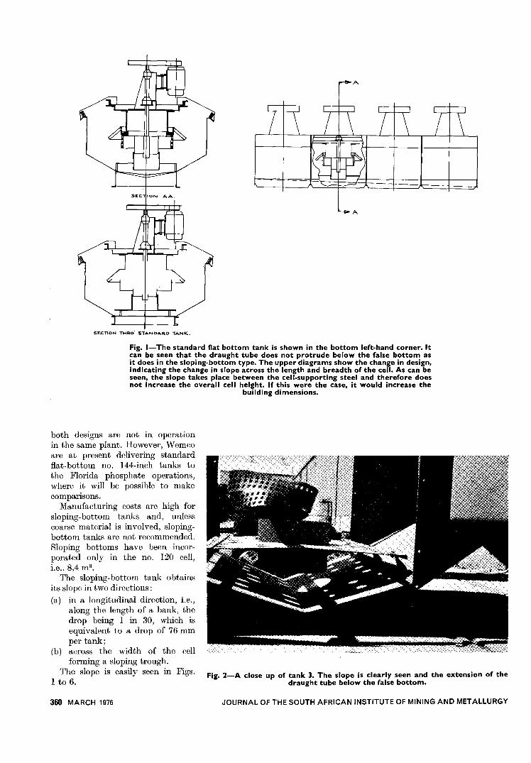
Fig. I-The standard flat bottom tank is shown in the bottom left-hand corner. Itcan be seen that the draught tube does not protrude below the false bottom asit does in the sloping-bottom type. The upper diagrams show the change in design,indicating the change in slope across the length and breadth of the cell. As can beseen, the slope takes place between the cell-supporting steel and therefore doesnot increase the overall cell height. If this were the case, it would increase the
building dimensions.
both designs are not in operationin the same plant. However, Wemcoare at present delivering standardflat-bottom no. 144-inch tanks tothe Florida phosphate operations,where it will be possible to makecomparIsons.
Manufacturing costs are high forsloping-bottom tanks and, unlesscoarse material is involved, sloping-bottom tanks are not recommended.Sloping bottoms have been incor-porated only in the no. 120 cell,i.e., 8,4 m3.
The sloping-bottom tank obtainsits slope in two directions:(a) in a longitudinal direction, Le.,
along the length of a bank, thedrop being 1 in 30, which isequivalent to a drop of 76 mmper tank;
(b) across the width of the cellforming a sloping trough.
The slope is easily seen in Figs.1 to 6.
360 MARCH 1976
Fig. 2-A close up of tank 3. The slope is clearly seen and the extension of thedraught tube below the false bottom.
JOURNAL OF THE SOUTH AFRICAN INSTITUTE OF MINING AND METALLURGY
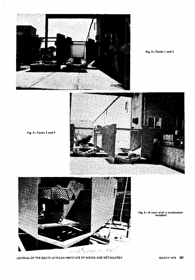
Fig. 3- Tanks I and 2
Fig. 4- Tanks 3 and 4
Fig. 5-A tank with a mechanisminstalled
JOURNAL OF THE SOUTH AFRICAN INSTITUTE OF MINING AND METALLURGY MARCH 1976 361
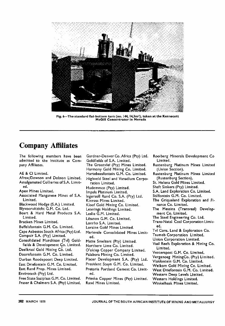
Fig. 6- The standard flat-bottom tank (no. 144, 14,3m3), taken at the KennecottMcGiII Concentrator in Nevada
Company AffiliatesThe following members have beenadmitted to the Institute as Com-pany Affiliates.
AE & Cl Limited.AfroxjDowson and Dobson Limited.Amalgamated Collieries ofS.A. Limit-
ed.Apex Mines Limited.Associated Manganese Mines of S.A.
Limited.Blackwood Hodge (S.A.) Limited.Blyvooruitzicht G.M. Co. Ltd.Boart & Hard Metal Products S.A.
Limited.Bracken Mines Limited.Buffelsfontein G.M. Co. Limited.Cape Asbestos South Africa (Pty) Ltd.Compair SA (Pty) Limited.Consolidated Murchison (Tvl) Gold-
fields & Development 10. Limited.Deelkraal Gold Mining Co. Ltd.Doornfontein G.M. Co. Limited.Durban Roodepoort Deep Limited.East Driefontein G.M. Co. Limited.East Rand Prop. Mines Limited.Envirotech (Pty) Ltd.Free State Saaiplaas G.M. Co. Limited.Fraser & Chalmers S.A. (Pty) Limited.
Gardner-Denver Co. Africa (Pty) Ltd.Goldfields of S.A. Limited.The Grootvlei (Pty) Mines Limited.Harmony Gold Mining Co. Limited.Hartebeesfontein G.M. Co. Limited.Highveld Steel and Vanadium Corpo-
ration Limited.Hudemmco (Pty) Limited.Impala Platinum Limited.Ingersoll Rand Co. SA (Pty) Ltd.Kinross Mines Limited.Kloof Gold Mining Co. Limited.Lennings Holdings Limited.Leslie G.M. Limited.Libanon G.M. Co. Limited.Lonrho S.A. Limited.Loraine Gold Mines Limited.Marievale Consolidated Mines Limit-
ed.Matte Smelters (Pty) Limited.Northern Lime Co. Limited.O'okiep Copper Company Limited.Palabora Mining Co. Limited.Placer Development S.A. (Pty) Ltd.President Stern G.M. Co. Limited.Pretoria Portland Cement Co. Limit-
ed.Prieska Copper Mines (Pty) Limited.Rand Mines Limited.
Rooiberg Minerals Development CoLimited.
Rustenburg Platinum Mines Limited(Union Section).
Rustenburg Platinum Mines Limited(Rustenburg Section).
St. Helena Gold Mines Limited.Shaft Sinkers (Pty) Limited.S.A. Land Exploration Co. Limited.Stilfontein G.M. Co. Limited.The Griqualand Exploration and Fi-
nance Co. Limited.The Messina (Transvaal) Develop-
ment Co. Limited.The Steel Engineering Co. Ltd.Trans-Natal Coal Corporation Limic-
ed.Tvl Cons. Land & Exploration Co.Tsumeb Corporation Limited.Union Corporation Limited.Vaal Reefs Exploration & Mining Co.
Limited.Venterspost G.M. Co. Limited.Vergenoeg MiningCo. (Pty) Limited.Vlakfontein G.M. Co. Limited.Welkom Gold Mining Co. Limited.West Driefontein G.M. Co. Limited.Western Deep Levels Limited.Western Holdings Limited.Winkelhaak Mines Limited.
362 MARCH 1976 JOURNAL OF THE SOUTH AFRICAN INSTITUTE OF MINING AND METALLURGY