Embed Size (px)
Citation preview
NASA Technical Memorandum 83664
Design Considerations for a 1 O-kW Integrated Hydrogen-Oxygen Regenerative Fuel Cell System
Mark A. Hoberecht, Thomas B. Miller, Lorra L. Rieker, and Olga D. Gonzalez-Sanabria Lewis Research Cenrer Cleveland, 04io
Prepared for the Nineteenth Intersociety Energy Conversion Engineering Conference cosponsored by the ANS, ASME, SAE, IEEE, AIAA, ACS, and AIChE San Francisco, California, August 19-24, 1984
https://ntrs.nasa.gov/search.jsp?R=19840014955 2018-07-14T06:14:56+00:00Z
Page 1 o f 4
DESIGN CONSIDERATIONS FOR A 10-kW INTEGRATED HYDROGEN-OXYGEN
REGENERATIVE FUEL CELL SYSTEM
Mark A. Hoberecht, Thomas 8. M i l l e r , Lo r ra L. Rieker, and Olga D . Gonzalez-Sanabrla
Na t iona l Aeronaut ics and Space A d m i n i s t r a t i o n Lewis Research Center Cleveland, Ohio 44135
ABSTRACT
I n t e g r a t i o n o f an a l k a l i n e f u e l c e l l subsystem w i t h an a l k a l i n e e l e c t r o l y s i s sub- system t o form a regenerat ive f u e l c e l l ( R F C ) system f o r l ow-ea r th -o rb i t (LEO) a p p l i c a t i o n s cha rac te r i zed by r e l a t i v e l y h i g h o v e r a l l r o u n d - t r i p e l e c t r i c a l e f f i c i e n c y . l ong l i f e , and h igh r e l i a b i l i t y i s p o s s i b l e w l t h present s t a t e - o f - t h e - a r t technology. A h y p o t h e t i c a l 10-kW system i s be ing computer modeled and s tud ied based on data f rom ongoing con- t r a c t u a l e f f o r t s i n both t h e a l k a l i n e f u e l c e l l and a l k a l i n e water e l e c t r o l y s i s areas. The a l k a l i n e f u e l c e l l technology i s be ing developed under an NASA-LeRC program w i t h Uni ted Technologies Corporat ion (UTC), u t i l - i z i n g advanced c e l l components and standard S h u t t l e - O r b i t e r system hardware. The a l ka - l i n e e l e c t r o l y s i s technology i s t h a t o f L i f e Systems, Inc . (LSI) , which uses a s t a t i c water vapor feed technique and scaled-up c e l l hardware being developed under an NASA-LeRC program. This paper addresses t h e computer- a ided study o f t h e performance, operat ing, and design parameters o f t h e h y p o t h e t i c a l sys tem.
INTRODUCTION
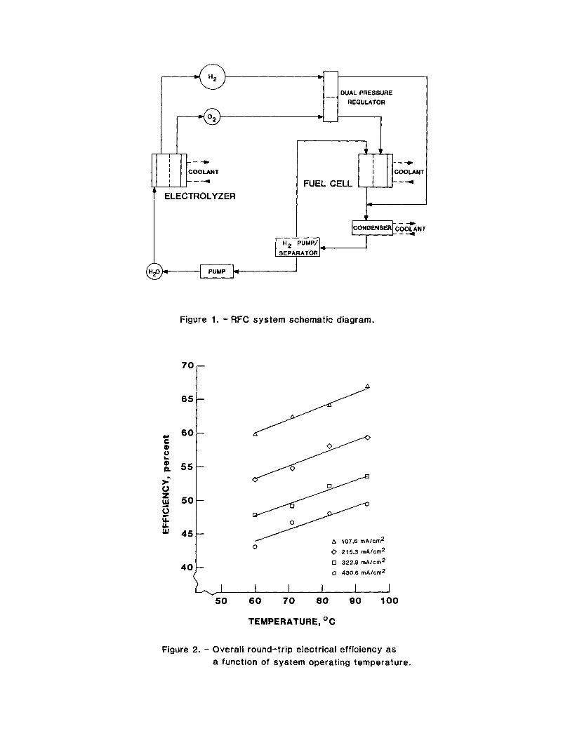
A simple schematic diagram o f t he hypo- t h e t i c a l 10-kW RFC system i s shown i n F ig . 1. The system cons is t s o f e l e c t r o l y s i s and f u e l c e l l stacks, reac tan t s torage tanks, a dual-pressure r e g u l a t o r , condenser, hydrogen pump/separator, and water pump. Coolant loops a re l oca ted i n t h e e l e c t r o l y s i s s tack, f u e l c e l l stack, and condenser. A u x i l i a r y plumbing and c o n t r o l s a re n o t inc luded.
Hydrogen, oxygen, and water a re t h e com- mon reactants . Dur ing t h e d a y l i g h t p o r t i o n o f a l ow-ea r th -o rb i t cyc le , t he e l e c t r o l y s i s subsystem w i l l r ece i ve power f rom an e x t e r n a l source, t y p i c a l l y a s o l a r a r ray , and produce hydrogen and oxygen f r o m water. E l e c t r o l y s i s occurs a t h igh pressure, and product gases en te r t h e storage tanks c o n t a i n i n g a f i x e d amount o f water vapor based on t h e temper- a ture, pressure, and e l e c t r o l y t e concen- t r a t l o n o f t h e e l e c t r o l y s i s stack. A dual-pressure r e g u l a t o r reduces t h e
pressure be fo re t h e humid.if ied gases a r e d e l i v e r e d from the storage tanks t o t h e fuel c e l l subsystem. Here, hydrogen and oxygen r e a c t t o form water d u r i n g the e c l i p s e p o r t j o n o f an o r b i t , d e l i v e r i n g power t o t h e spacecraf t bus. Oxygen en te rs t h e f u e l c e l l stack d i r e c t l y , w h i l e hydrogen enters a r e - c y c l e l oop downstream o f t h e f u e l c e l l stack. The purpose o f t h i s r e c y c l e l oop i s t o remove product water as vapor from t h e hydrogen s ide o f t h e f u e l c e l l stack. The hydrogen gas l e a v i n g t h e f u e l c e l l conta ins an amount o f water vapor based on t h e temper- a tu re , pressure, and e l e c t r o l y t e concen- t r a t i o n o f t h e f u e l c e l l stack. This gas stream mixes w i t h the incoming hydrogen from t h e s torage tank and t h e r e s u l t i n g stream enters t h e condenser, where i t s temperature i s reduced and a c e r t a i n f r a c t i o n o f t he water vapor i s condensed. The gas and l i q u i d phases o f t h i s stream a r e separated i n the hydrogen pump/separator. The gas i s r e c i r c u - l a t e d through t h e f u e l c e l l stack t o remove a d d i t i o n a l product water as vapor, w h i l e t h e l i q u i d water i s pumped t o h igher pressure and d e l i v e r e d t o i t s storage tank. The c y c l e i s repeated as l i q u i d water enters the e lec- t r o l y s i s stack and product gases a re formed once again.
PERFORMANCE. OPERATING. AND OESIGN PARAMETERS
The goal i n energy s torage system design i s t o develop a system w i t h an optimum combi- n a t i o n o f o v e r a l l r o u n d - t r i p e l e c t r i c a l e f - f i c i e n c y , l i f e , r e l i a b i l i t y , and both g r a v i m e t r i c and vo lumet r l c energy densi ty , f o r t he t o t a l spacecraf t e l e c t r i c a l power system f o r a s p e c i f i c m iss ion a p p l i c a t l o n . The energy s torage system i s j u s t one p o r t i o n o f t h e e l e c t r i c a l power system, b u t i t s per- formance parameters can have major i m p l i - ca t i ons f o r t he o the r two p o r t i o n s o f t h e system; the energy convers ion system and t h e power management, d i s t r i b u t i o n , and c o n t r o l system. Weight i s a key des ign c r i t e r i o n f o r t h e e n t i r e e l e c t r i c a l power system. An energy storage system w i t h h igh o v e r a l l r o u n d - t r i p e l e c t r i c a l efficiency w i l l m i n i - mize energy convers ion system wejght (1 ) and, i n the case o f a s o l a r a r ray , lessen i t s area as w e l l . Th is has a d i r e c t e f f e c t upon drag and reboost f u e l requirements f o r t he t o t a l spacecraf t . A h i g h vo l tage system w i l l
Page 2 o f 4
decrease the requ l red c u r r e n t f o r a g i ven power l e v e l and thus mlnlmlze conductor weight throughout a l l p o r t l o n s o f t h e e l e c t r l c a l power system. Another major des ign c r l t e r i o n i s l i f e - c y c l e cos t . An energy storage system w i t h l ong l i f e w l l l mlnlmlze l l f e - c y c l e cos t due t o the reduced number o f energy storage system rep lace- ments. This holds t r u e f o r t h e o the r two p o r t l o n s o f t he e l e c t r l c a l power system as we1 1.
Performance o f t h e h y p o t h e t l c a l 10-kW RFC system I s determined f rom I t s ope ra t i ng parameters; temperature, c u r r e n t dens i t y , pressure, and e l e c t r o l y t e concent ra t ion . Operat ing temperature and c u r r e n t d e n s l t y have t h e most s l g n i f l c a n t Impact upon energy s to rage system performance. Low opera t i ng temperatures w i l l reduce chemical degradat ion o f I n t e r n a l c e l l components and extend l l f e , w h i l e low c u r r e n t d e n s l t l e s w l l l m in imize e lec t rochemlca l degradation, improve o v e r a l l r o u n d - t r i p e l e c t r i c a l e f f i c i e n c y , and a l s o extend l l f e ( 2 ) . Therefore, h l g h o v e r a l l r o u n d - t r i p e l e c t r l c a l e f f l c l e n c y and long l l f e can be achieved by opera t l ng t h e energy s to rage system a t r e l a t i v e l y low l e v e l s o f temperature and c u r r e n t dens i t y .
Energy storage system des ign parameters r e l a t e t o system c o n f i g u r a t i o n and a r e se lec ted t o o b t a i n maxlmum r e l l a b i l i t y w i th mlnlmum p a r a s i t i c power losses. Th ls can be achleved through s i m p l i c i t y o f des lgn f o r thermal and f l u l d s management, and by a re - d u c t i o n i n t h e t o t a l number o f a n c i l l a r y hardware components. Novel I n t e g r a t i o n techniques f o r the f u e l c e l l and e l e c t r o l y z e r cou ld a l s o be o f b e n e f i t . System des ign con- s i d e r a t i o n s Inc lude the a p p l l c a b l e mass and energy balances which must be eva lua ted be fo re f i n a l s e l e c t i o n o f proper system design parameters can be made. From a thermal management s tandpo in t , t h l s i nvo l ves t h e q u a n t l t y o f waste heat be ing removed f rom t h e t h r e e separate coo lan t loops, I t s d l s t r i - b u t i o n t o o the r p a r t s o f t he system r e q u l r l n g heat a t var ious t imes d u r l n g a cyc le , and i t s eventua l d e l i v e r y t o a r a d i a t o r . Thermal sha r ing and m in im iz ing heat losses a r e o f p r imary concern. From a f l u i d s management s tandpo ln t , t h e mass f l o w r a t e o f t h e hydro- gen r e c y c l e stream I n the f u e l c e l l subsystem I s a major c o n t r i b u t o r t o t h e t o t a l p a r a s i t i c power l oss o f t he system. A condenser temperature which reduces t h l s mass f l o w r a t e t o a reasonable l e v e l i s necessary. I n f a c t , i n c o r p o r a t i o n o f a n c i l l a r y hardware com- ponents which minlmlze p a r a s i t i c power losses throughout the R F C system, w h i l e s t i l l main- t a i n i n g r e l i a b l e performance, i s o f paramount Importance.
Eva lua t i on o f gas, e l e c t r o l y t e . and water management i s a l s o necessary be fo re s e l e c t l o n o f app rop r ia te system des ign para- meters can be achieved. Humid i f ied gases must always be maintained a t temperatures above t h e i r respec t i ve dew p o i n t s i n o rder t o avo ld condensat ion and I t s i nhe ren t prob- lems. Dry ing o f t he gases and subsequent regenera t ion o f water vapor can thus be avoided. E l e c t r o l y t e temperatures, pres- sures, and concent ra t lons determine bo th t h e q u a n t i t y o f water vapor i n t h e gas streams and the amount o f d i sso l ved gases i n t h e l l q u l d streams o f t h e e l e c t r o l y s i s and f u e l c e l l subsystems. These temperatures, pres- sures, and concent ra t ions must be managed p r o p e r l y i n o rder t o avo ld e v o l u t i o n o f d i s - solved gases f rom l i q u l d so lu t i ons , which would necess i ta te gas adso rp t i on o r recombl- na t i on . Taking I n t o account t h e performance, opera t lng , and des ign parameters, i n con- j u n c t i o n w i t h t h e approp r ia te mass and energy balances and gas, e l e c t r o l y t e , and water management techniques I s a d e t a i l e d and lengthy process. However, a computer program used t o model t h e h y p o t h e t i c a l 10-kW RFC system l n d l c a t e s t h a t a system f o r LEO ap- plications w l t h an o v e r a l l r o u n d - t r i p e lec- t r i c a l e f f i c i e n c y o f g rea te r than 59 percent, l l f e g rea te r than 70 000 h r . and h i g h r e l l a b l l l t y I s w i t h i n p resent s ta te -o f - the- a r t technology.
COMPUTER MODEL
A computer program developed a t NASA- LeRC u t i l l z l n g a se r ies o f v a r i a b l e I n p u t parameters I s used t o model t h e system. The I n p u t Inc ludes bo th t h e opera t i ng and design parameters f o r t h e h y p o t h e t i c a l 10-kW RFC system, w l t h performance parameters generated as ou tpu t . The key opera t i ng parameters i n c l u d e temperature, c u r r e n t dens i t y , pres- sure, and e l e c t r o l y t e concen t ra t i on f o r the f u e l c e l l and e l e c t r o l y s i s subsystems. The temperature and c u r r e n t d e n s i t y a r e assumed t o be equal f o r each subsystem and changed f o r each separate run o f t h e program. The pressure and e l e c t r o l y t e concen t ra t i on o f each subsystem a r e Independent o f one another and f i xed . The major des ign parameter I s t h e condenser temperature, which has a d l r e c t Impact on mass and energy balances and gas, e l e c t r o l y t e , and water management consider- a t l o n s f o r t he e n t l r e RFC system. Th is parameter I s a l lowed t o vary w l t h l n each run o f t he program.
A m a t r i x o f runs I s made w i t h t h e computer program a t var ious l e v e l s o f temper- a t u r e and c u r r e n t d e n s l t y i n order t o gener- a t e d l f f e r e n t values f o r o v e r a l l r o u n d - t r i p e l e c t r i c a l e f f i c i e n c y , l l f e , g r a v l m e t r l c energy dens i t y , and vo lumet r i c energy dens l t y .
Page 3 o f 4
P l o t s o f these f o u r performance parameters versus t h e two opera t i ng parameters f rom t h e m a t r i x o f runs a re shown i n F igs. 2 t o 9.
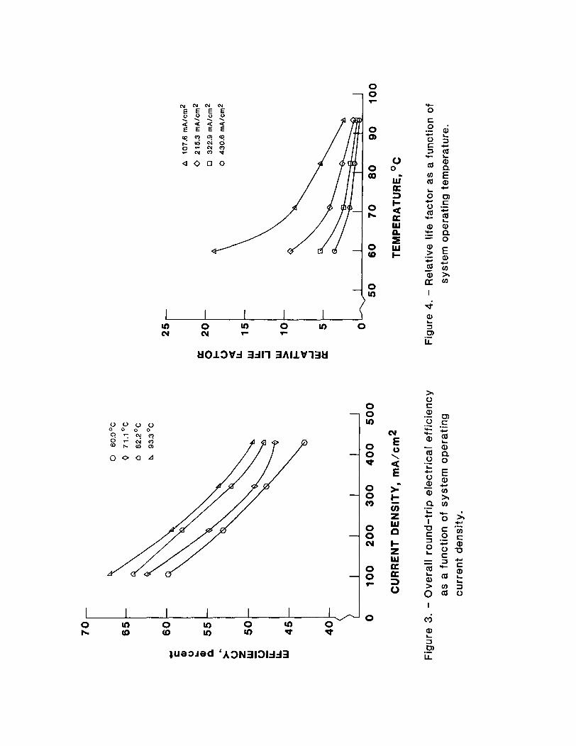
The e f f i c i e n c y p l o t s ( f i g s . 2 and 3) i n d i c a t e t h a t o v e r a l l r o u n d - t r i p e l e c t r i c a l e f f i c i e n c y increases as temperature i n - creases, bu t decreases as c u r r e n t d e n s i t y Increases. The temperature e f f e c t i s due t o Improved r e a c t i o n k i n e t i c s w i t h i n c r e a s i n g temperature. The c u r r e n t d e n s i t y e f f e c t r e s u l t s f rom l a r g e r p o l a r i z a t i o n losses with i n c r e a s i n g c u r r e n t d e n s i t y . For t h i s m a t r i x of runs, t h e e f f i c i e n c y range i s between 43.1 percent and 66.9 percent .
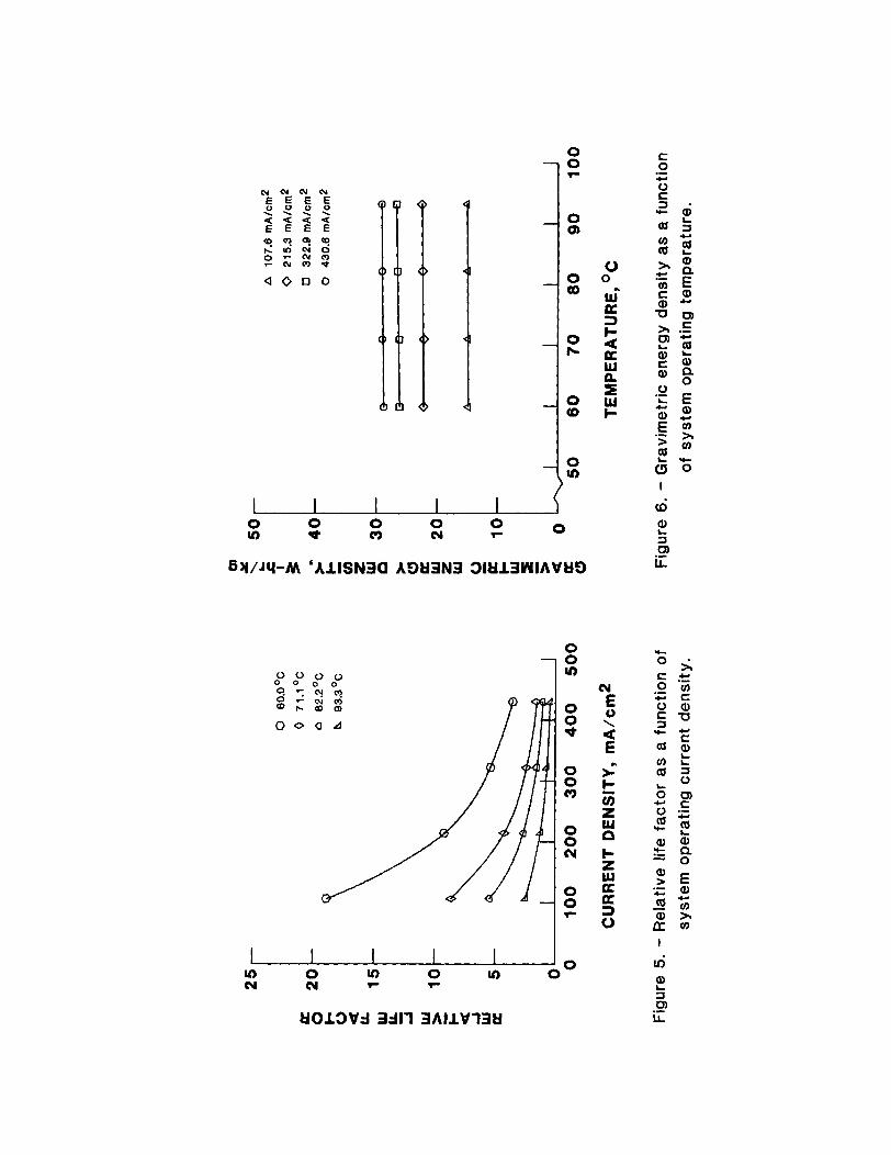
The l i f e p l o t s ( f i g s . 4 and 5 ) show t h a t t h e r e l a t i v e l i f e f a c t o r decreases as bo th temperature and c u r r e n t d e n s i t y increase. Thls i s due t o t h e accelerated chemical and e lect rochemical degradat ion o f i n t e r n a l c e l l components w i t h i nc reas ing temperature and c u r r e n t dens i t y . End o f l i f e i s s imply de f i ned as t h e system dropping ou t o f I t s s p e c i f i e d vo l tage r e g u l a t i o n range. The t o t a l l l f e f o r t h e h y p o t h e t l c a l 10-kW RFC system w i t h present technology ranges between 2000 and 75 000 h r , which approx imate ly co r - responds t o a r e l a t i v e l l f e f a c t o r o f between 0.5 and 20.0.
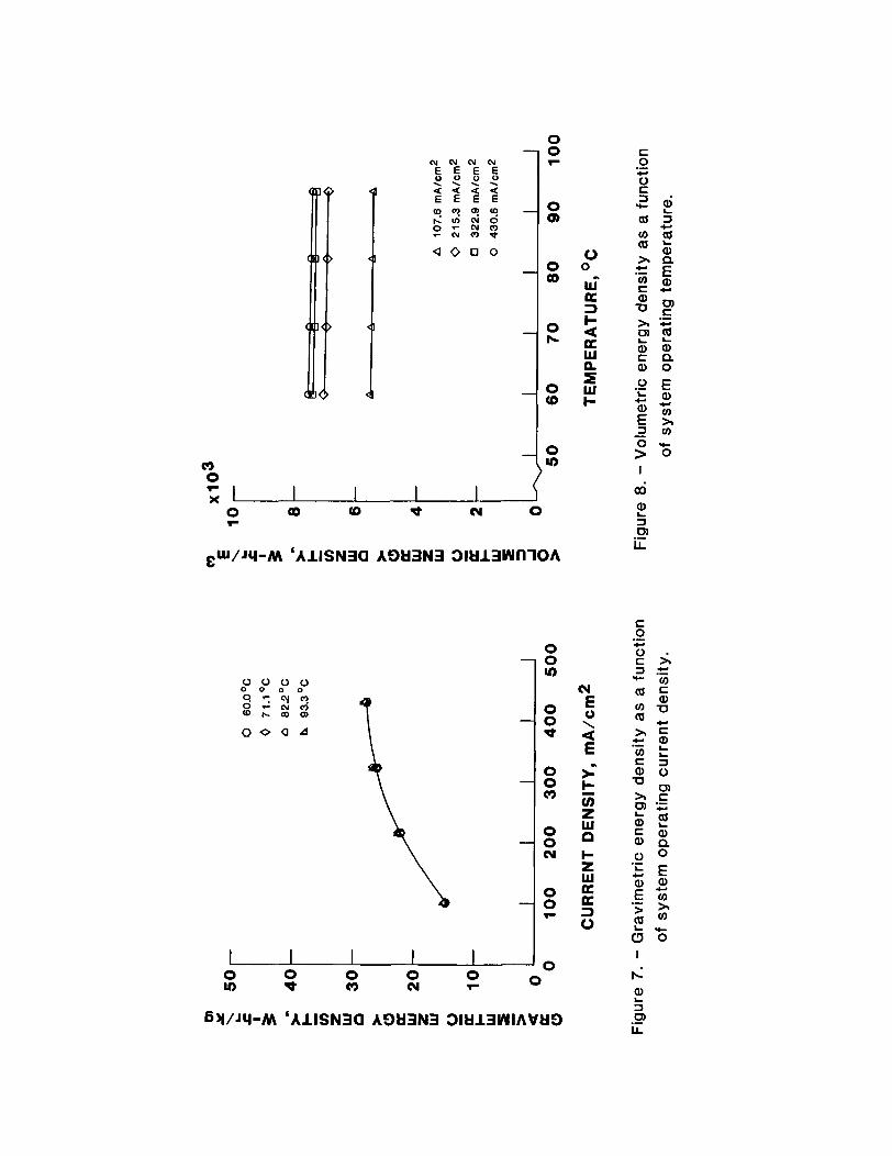
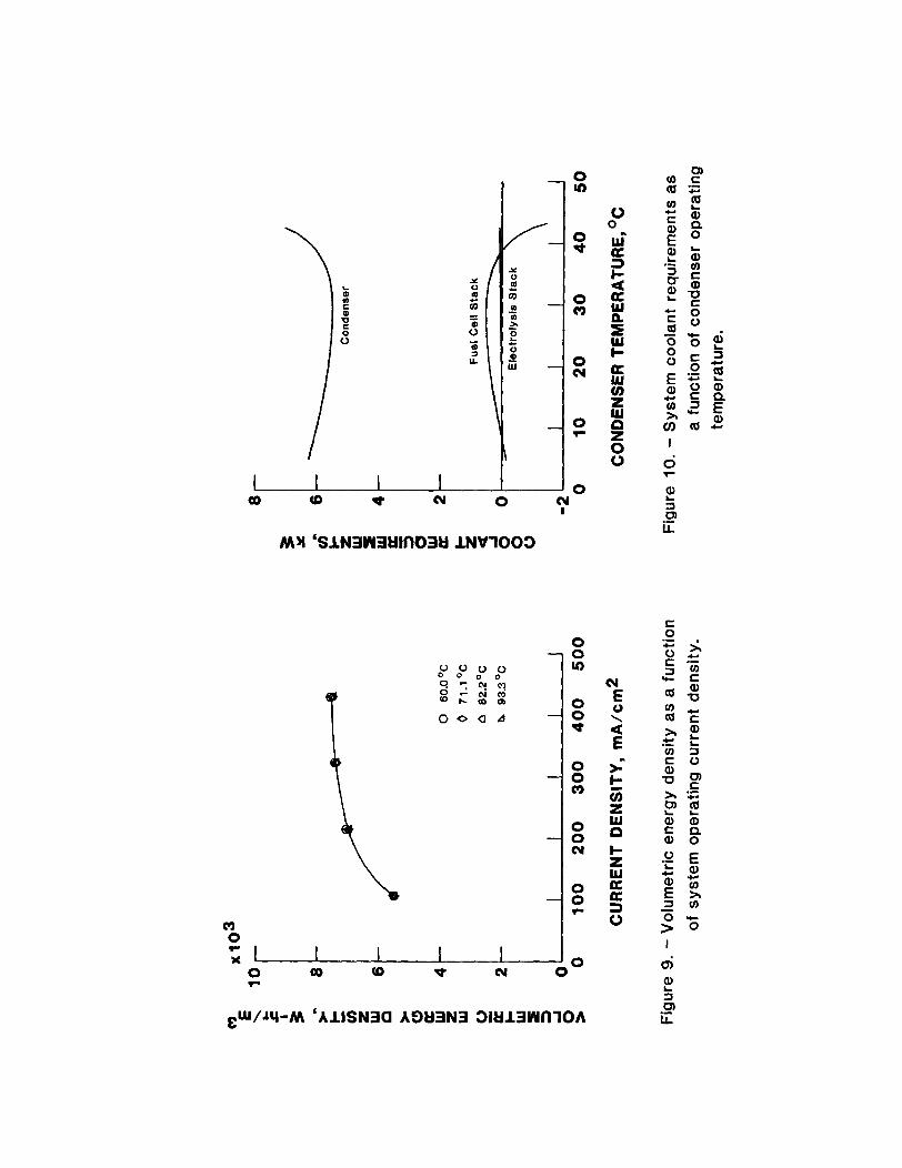
The g r a v i m e t r i c and vo lumet r l c energy d e n s i t y p l o t s ( f l g s . 6 t o 9) revea l t h e i n - crease i n bo th these performance parameters w l t h i nc reas ing c u r r e n t dens i t y , w h i l e temperature has l i t t l e e f f e c t . Current dens i t y , as opposed t o temperature, has a s i g n i f i c a n t i n f l u e n c e on the t o t a l number o f c e l l s per stack, which I s r e f l e c t e d i n t h e weight and volume values. For t h i s m a t r i x o f runs, t h e g r a v l m e t r l c energy d e n s i t y range i s f rom 14.8 W-hr/kg t o 29.1 W-hr/kg, w h i l e t h e vo lumetr ic energy dens i t y range i s between 5450 W-hr/m3 and 7535 W-hr/m3.
The t o t a l o f these performance p l o t s taken together may serve as a u s e f u l t o o l f o r s e l e c t i o n o f an optimum RFC system. a p p l i c a t i o n s , t h i s system should y t e l d h i g h o v e r a l l r o u n d - t r i p e l e c t r i c a l e f f i c i e n c y , l ong l i f e , and h i g h r e l l a b l l i t y . P r e l i m i n a r y i n s p e c t i o n o f t h e p l o t s revea ls t h a t f o r a se lected case opera t i ng a t a temperature o f 60.0" C and a c u r r e n t d e n s i t y o f 107.6 mA/cm2, both r e l a t i v e l y low values, t h e h y p o t h e t i c a l 10-kW RFC system w i l l have an o v e r a l l r o u n d - t r i p e l e c t r i c a l e f f i c l e n c y o f 59.8 percent, l i f e o f approximately 73 000 h r , g rav lme t r l c energy d e n s i t y o f 14.8 W-hr/kg, and vo lumetr ic energy d e n s i t y o f 5500 W-hr/mJ ( t a b l e 1 ) . t r a d e o f f s remain t o be performed be fo re f i n a l system eva lua t i on I s completed.
For LEO
Only t h e des ign
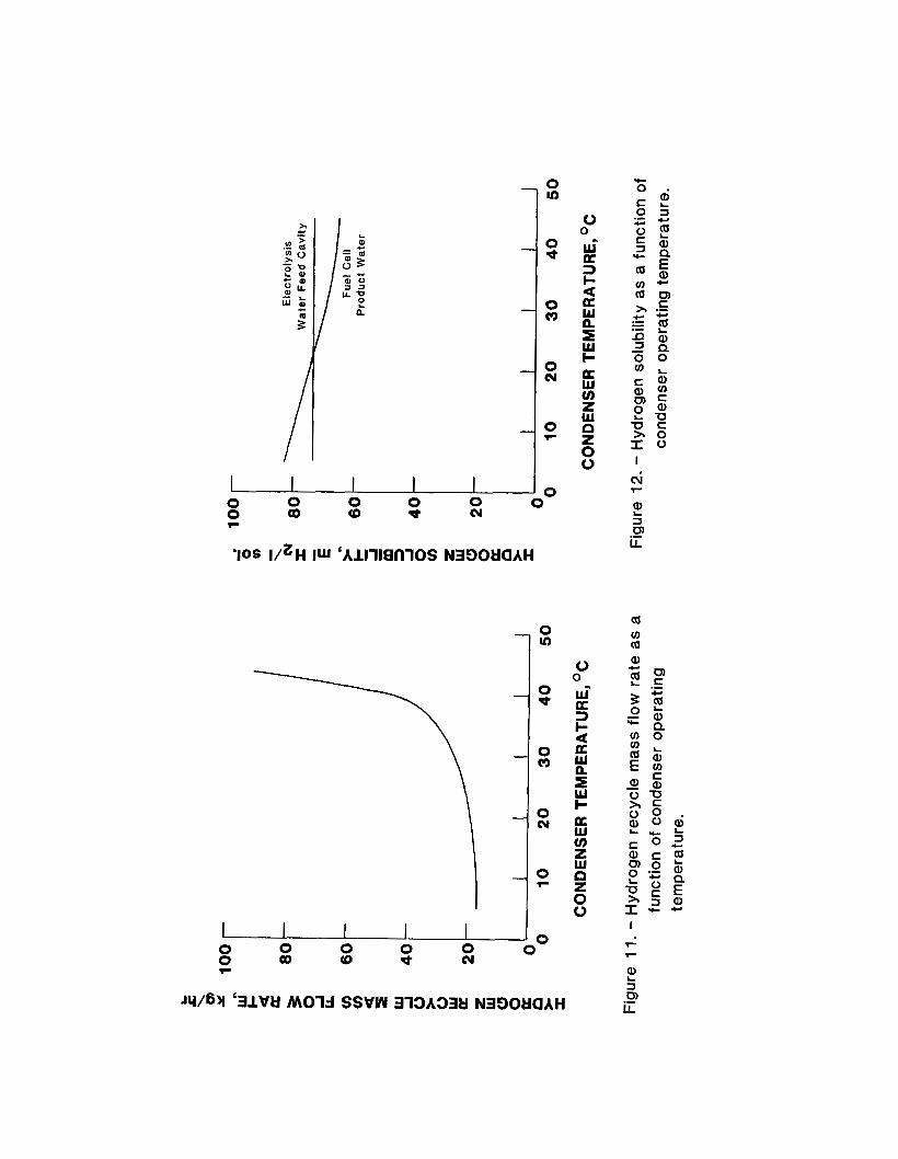
One s e r i e s o f des ign t r a d e o f f s i nvo l ves t h e m a s s and energy balances f o r t h e system, c h i e f l y t h e t h r e e separate coolant requ i re - ments and t h e f u e l c e l l subsystem hydrogen r e c y c l e stream mass f l o w r a t e . P l o t s o f these des ign parameters versus condenser temperature a r e shown i n F igs . 10 and 11 f o r t h e se lec ted case. coo lan t requirements o f t h e e l e c t r o l y s l s stack, f u e l c e l l stack, and condenser. A t condenser temperatures approaching t h e dew p o i n t temperature o f t h e hydrogen r e c y c l e stream, 47.7" C, t h e r e c y c l e r a t e becomes so l a r g e t h a t t h e f u e l c e l l subsystem coo lan t requirements a r e borne t o t a l l y by t h e con- denser. Thus, a t condenser temperatures above 39.0" C, heat would have t o be suppl ied t o t h e f u e l c e l l i n o rde r t o ma in ta in i t s ope ra t i ng temperature. S i m i l a r l y , a t con- denser temperatures below 8.7" C, heat again would have t o be d e l i v e r e d t o the f u e l c e l l t o ma in ta in I t s o p e r a t i n g temperature, i n t h i s instance due t o t h e hydrogen r e c y c l e stream being so low i n temperature. F igu re 11 shows t h e Inc reas ing hydrogen r e c y c l e stream mass f l o w r a t e requirement w i t h i n - creas ing condenser temperature. T h i s f l o w r a t e becomes p r o h i b i t i v e l y l a r g e as t h e con- denser temperature approaches t h e dew p o i n t temperature o f t h e hydrogen recyc le stream. These t rends combine t o l i m i t t h e system opera t i ng range f o r t h e condenser temperature t o between 8.7" and 39.0" C, where t h e coo lan t requirements a re shared by a l l coo lan t loops.
gas, e l e c t r o l y t e , and water management con- s i d e r a t i o n s f o r t h e system, s p e c i f i c a l l y t h e q u a n t i t y o f d l sso l ved hydrogen I n t h e f u e l c e l l product water once i t enters the e lec- t r o l y s i s water feed c a v i t y . dep ic t s t h e constant hydrogen s o l u b i l i t y i n t h i s c a v i t y , which i s ma in l y a f u n c t i o n o f pressure and e l e c t r o l y t e concentrat ion; and t h e decreasing hydrogen s o l u b i l i t y I n t h e f u e l c e l l product water as t h e condenser temperature increases. For t h i s se lected case, hydrogen e v o l u t i o n f rom t h e e l e c t r o l y - s i s feed s o l u t i o n w i l l no t t ake p lace when condenser temperatures a re above 22.9" C. The p r a c t i c a l l i m i t f o r t h e condenser temper- a t u r e i s thus i n t h e range 22.9" t o 39.0' C , where a l l coo lan t requirements and the hydro- gen r e c y c l e stream mass f l o w r a t e are m i n i - mized, and d i sso l ved hydrogen remains i n s o l u t i on.
F igu re 10 dep ic t s t h e
Another design t r a d e o f f i nvo l ves t h e
F igure 12
CONCLUSIONS
The major requirements o f any energy s torage system f o r l ow-ea r th -o rb i t a p p l i - ca t i ons a re h i g h o v e r a l l r o u n d - t r i p e l e c t r i - c a l e f f i c i e n c y , l ong l i f e , and h i g h
Page 4 o f 4
r e l i a b i l i t y . these requirements through proper e v a l u a t i o n o f system t r a d e o f f s and f i n a l s e l e c t i o n o f system opera t i ng and design parameters. A computer program developed a t NASA-LeRC used t o model a h y p o t h e t i c a l 10-kW RFC system i n d i c a t e s t h a t a system w i t h an o v e r a l l r o u n d - t r i p e l e c t r i c a l e f f i c i e n c y o f 59.8 percent, l i f e g rea te r than 70 000 h r , and h i g h r e l i a b i l i t y i s poss ib le w i t h present s ta te -o f - the -a r t technology.
An RFC system i s a b l e t o meet REFERENCES
1. R. E. MARTIN, "E lect rochemical Energy Storage f o r an O r b i t l n g Space Stat ion, I1 Unl ted Technologies Corporat ion, Power Sys tems D i v i s i on, NASA CR-165436, FCR-3142 (Dec. 1981). 2. M. A. HOBERECHT, and D. W. SHEIBLEY, " L i f e Considerat ions o f Hydrogen-Oxygen Regenerative Fuel C e l l Systems f o r Energy Storage i n Low-Earth-Orbit App l i ca t i ons , " Extended Abstracts , vo l . 83-2. E l e c t r o - chemical Soc ie ty F a l l Meeting, pp. 197-198. Washington, D.C. (1983).
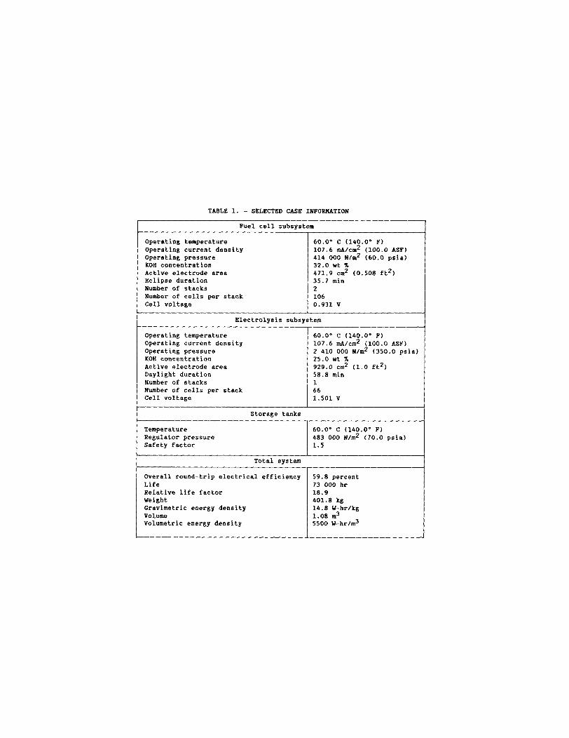
TABLE 1. - SELECTED CASE INFORMATION
Temperature Regulator pressure Safety factor
Fuel cell subsystem I
60.0" C (140.0" F) 483 000 N/m2 (70.0 psia) 1.5
Operating temperature Operating current density Operating pressure KOH concentration Active electrode area Eclipse duration Number of stacks Number of cells per stack Cell voltage
60.0' C (140.0° P) 107.6 mA/cm2 (100.0 ASF) 414 000 N/m2 (60.0 psia) 32.0 ut X 471.9 cm2 (0.508 ft2) 35.7 min 2 106 0.931 V
1
Electrolysis subsystem
Operating temperature Operating current density Operating pressure KOH concentration Active electrode area Daylight duration Number of stacks Number of cells per stack Cell voltage
60.0" C (140.0" F) 107.6 mA/cm2 (100.0 ASF) 2 410 000 N/m2 (350.0 psia) 25.0 wt X 929.0 cm2 (1.0 ft2) 58.8 min 1 66 1.501 V
Overall round-trip electrical efficiency Life Relative life factor Weight Gravimetric energy density Volume Volumetric energy density
59.8 percent 73 000 hr 18.9 401.8 kg 14.8 U-hr/kg 1.08 m3 5500 W-hrlm3
. t '
m - -
Figure 1. - RFC system schematic diagram.
DUAL PRESSURE REGULATOR
? O r
I I I I COOLANT
--*
I I
--4
' ELECTROLYZER
65
u 60 c al 0 L
55
i ,+ I --+ I I COOLAN1 I --+ FUEL CELL !
4
A 107.6 mAlcm2
o 215.3 mAlcm2
o 322.9 mA/cm2
o 430.6 mAlcm2
0
1 50 60 7 0 80 90 100
TEMPERATURE, OC
Figure 2. - Overall round-trip electrical efficiency as a function of system operating temperature.
o o a d
0 0
pc w n I w I-
C
Y - I . -
a b
L @ @ zcp
0 -
I
x
0 0 m
0 0 t
0 0 1 c') 0 0
0 0 i F
0 \ a E
N N N C Y . 5$!{ a a a a E E E E
- 0 r
- 0 Q,
- 0 0
- 0 IC
- 0 (D
- 0 v)
. a 0 0 0
- 0 r
- 0 Q,
- 0 0
- 0 IC
- 0 (D
- 0 v)
r v) 0 u) O 0
r F u) 0 N N
0 0
cu E
a E
0 \
I
ui
tlO13V3 3311 3 A l l W 7 3 t i
c3 0
1 I I I I
0 0 u)
0 0 t
0 0 c3
0 0 cy
0 0 r
0 0 0
F 0 0 0 0 u) t c3 cy
6YIJl4-M ‘ A I I S N 3 Q AOL13N3 31L113W1AWO
cy E
a E G i5
n
0 \
c z W
c z W K
3 0
a
- 0
-
rn 0 r X I
- cy I
t cy 0
M Y ‘SlN3W3Lll~O3tl l N V l 0 0 3
- 0 v)
0 - 0
P
0 - 0
(3
0 - 0
cy
0 0 r
o o a ~
0 0
w“ K 3 c 4 K W
w c K w v) z w 2 0 0
B
n
f a LA .-
0 0 0 0 0 Qo (0 t <rl
0 0 r
-10s V Z H lu 'Alll18fllOS N39OWAH
0 0 w" a 3 I- d a w n 5 w c
I
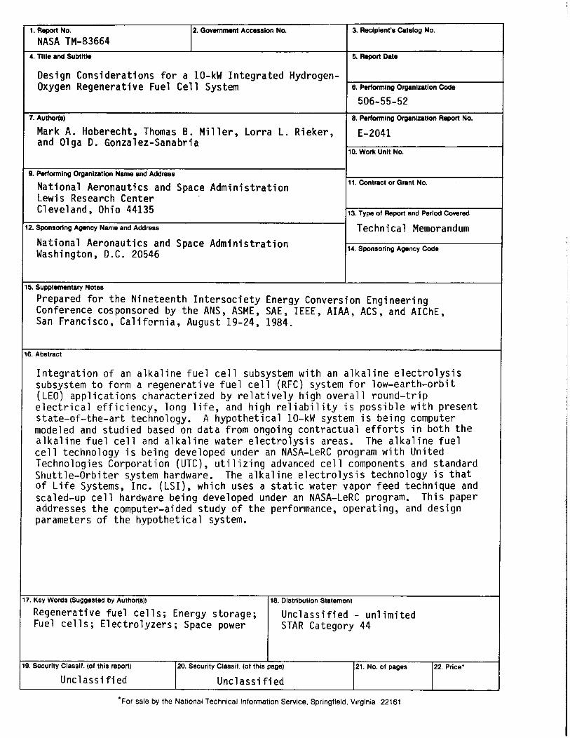
1. Report No. 2. Government Accession No.
NASA TM-83664 4. Titie and Subtitle
Design Considerat ions f o r a 10-kW I n t e g r a t e d Hydrogen- Oxygen Regenerative Fuel C e l l System
7. Author(a)
Mark A. Hoberecht, Thomas B. M i l l e r , Lor ra L. Rieker, and Olga D. Gonzalez-Sanabria
3. Recipient's Catalog No.
5. Report Date
6. Performing Organization Code
506-55-52 8. Performing Organization Report No.
E-2041
10. Wotk Unit No.
11. Contract or Grant No.
Technical Memorandum
Q. Pwforming Organization Name and Address
Nat iona l Aeronaut ics and Space Admin i s t ra t i on Lewis Research Center C1 eve1 and , Ohio 44135
12. Sponsoring Agency Name and Address
17. Key Words (Suggested by Author@))
Regenerat ive f u e l c e l l s ; Energy storage; Fuel c e l l s ; E l ec t ro l yze rs ; Space power
Nat ional Aeronaut ics and Space Admin i s t ra t i on Washington, D.C. 20546
18. Distribution Statement
Unc lass i f i ed - un l i m i t ed STAR Category 44
14. Sponsoring Agency Code 1
19. Security Classif. (of this report)
Uncl ass i f i ed
I 15. Supplementary Notes
Prepared f o r t h e Nineteenth I n t e r s o c i e t y Energy Conversion Engineer ing Conference cosponsored by t h e ANS, ASME, SAE, IEEE, A I A A , ACS, and AIChE, San Francisco, C a l i f c r n i a , August 19-24, 1984.
20. Security Classif. (of this page) 21. No. of pages 22. Price'
Unc 1 ass i f i ed
I n t e g r a t i o n o f an a l k a l i n e f u e l c e l l subsystem w i t h an a l k a l i n e e l e c t r o l y s i s subsystem t o form a regenera t ive f u e l c e l l (RFC) system f o r low-ear th-orb i t (LEO) a p p l i c a t i o n s charac ter ized by r e l a t i v e l y h igh o v e r a l l r ound- t r i p e l e c t r i c a l e f f i c i e n c y , long l i f e , and h i g h r e l i a b i l i t y i s p o s s i b l e w i t h p resent s ta te-of - the-ar t technology. A hypo the t i ca l 10-kW system i s be ing computer modeled and s tud ied based on da ta f rom ongoing con t rac tua l e f f o r t s i n bo th t h e a l k a l i n e fue l c e l l and a l k a l i n e water e l e c t r o l y s i s areas. c e l l technology i s be ing developed under an NASA-LeRC program w i t h Un i ted Technologies Corporat ion (UTC), u t i 1 i z i n g advanced c e l l components and standard Shu t t l e -Orb i te r system hardware. of L i f e Systems, Inc. (LSI) , which uses a s t a t i c water vapor feed technique and scaled-up c e l l hardware be ing developed under an NASA-LeRC program. Th is paper addresses t h e computer-aided s tudy o f t h e performance, operat ing, and des ign parameters o f t h e hypo the t i ca l system.
The a l k a l i n e f u e l
The a l k a l i n e e l e c t r o l y s i s technology i s t h a t
IIIUI