Embed Size (px)
Citation preview
Design & Co-design of Embedded Systems
Hardware-Software Co-verification
Maziar Goudarzi
Fall 2005 Design & Co-design of Embedded Systems
2
Today Program
Introduction to Hardware-Software Co-verification Techniques
A Methodology for HW-SW Co-simulation using SystemC
Fall 2005 Design & Co-design of Embedded Systems
3
Validation
Validation vs. verificationApproaches to validation
Emulation Simulation (co-simulation) Formal verification
Fall 2005 Design & Co-design of Embedded Systems
4
Validation (cont’d)
Simulation cannot ensure correctness, but still useful
Heterogeneity Weakly heterogeneous
Lumped, GP computing systems. Simple control systems
Can be simulated by extending HDL simulators Strongly heterogeneous
Cellular phones, avionics Require specialized simulation environments
Fall 2005 Design & Co-design of Embedded Systems
5
Co-Validation
Simulator features for weakly heterogeneous systems Adequate timing accuracy Fast execution Visibility of internal registers for
debugging
Fall 2005 Design & Co-design of Embedded Systems
6
Co-Validation (cont’d)
Strategy 1: Use HDL simulator + HDL models for processor and ASICs Long HW simulation time for each
instruction: accuracy vs. speed tradeoff
Fall 2005 Design & Co-design of Embedded Systems
7
Co-Validation (cont’d)
Strategy 2: avoid processor HDL model Use HW/SW comm. Protocol SW is compiled and communicates with
the HDL simulator which models ASIC HDL simulator is bottle-neck Internal registers not visible
Fall 2005 Design & Co-design of Embedded Systems
8
Validation (cont’d)
Strategy 3: Emulate HW on a re-configurable platform Automatic partitioning tools to minimize
system-simulation time have been developed
Visibility of internal states is limited => probable slow debugging
Fall 2005 Design & Co-design of Embedded Systems
9
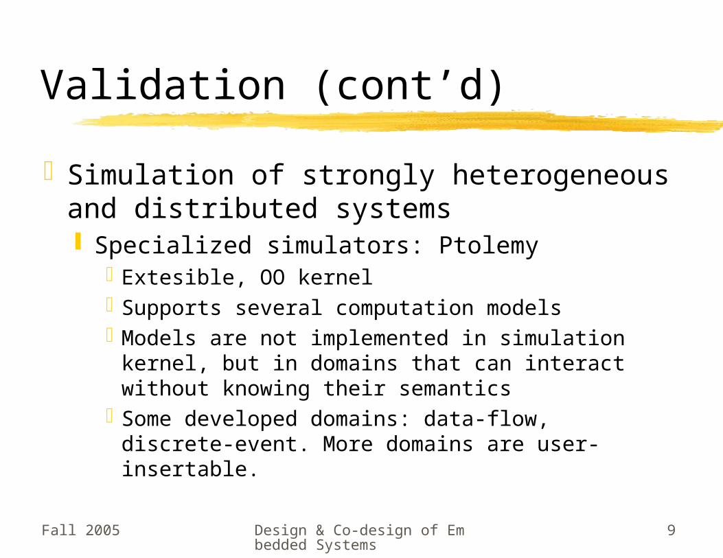
Validation (cont’d)
Simulation of strongly heterogeneous and distributed systems Specialized simulators: Ptolemy
Extesible, OO kernelSupports several computation modelsModels are not implemented in simulation
kernel, but in domains that can interact without knowing their semantics
Some developed domains: data-flow, discrete-event. More domains are user-insertable.
Hardware-Software Co-verification
Methodology for HW/SWCo-simulation in SystemC
Fall 2005 Design & Co-design of Embedded Systems
11
Topics
IntroductionDesign FlowProcessor ModelsImplementation: 8051Conclusion
Reference:
L. Semeria & A. Ghosh, “Methodology for Hardware/Software Co-Verification in C/C++”, in ASP-DAC 2000
Reference:
L. Semeria & A. Ghosh, “Methodology for Hardware/Software Co-Verification in C/C++”, in ASP-DAC 2000
Fall 2005 Design & Co-design of Embedded Systems
12
Introduction
Shrinking device sizes => all digital components on a single chip
Software is traditionally fully tested after hardware is fabricated => long TTM
Integrating HW and SW earlier in the design cycle => better TTM
Co-simulation involves Simulating a processor model along with
custom HW (usually described in HDL)
Fall 2005 Design & Co-design of Embedded Systems
13
Introduction (cont’d)
Heterogeneous co-simulation environments (C-VHDL or C-Verilog) RPC or another form of inter-process
communication between HW and SW simulators
High overhead due to high data transmission between the simulators
Fall 2005 Design & Co-design of Embedded Systems
14
Introduction (cont’d)
Recently HW synthesis techniques from C/C++ are more investigated Eliminates C to HDL translation for synthesis
=> higher productivityReduces translation timeEliminated bugs introduced during this
translation Easier verification by
re-using testbenches developed during system validation phase
enabling HW-SW co-verification and performance estimation at very early stages of design
Fall 2005 Design & Co-design of Embedded Systems
15
Introduction (cont’d)
In this paper, authors present How HW-SW co-verification is
performed in a C/C++ based environment
HW and SW are both described in C++ (SystemC)Other C/C++ based approaches: PTOLEMY,
and CoWare N2C,
Methodology for HW/SWCo-verification in SystemC
Design Flow
Fall 2005 Design & Co-design of Embedded Systems
17
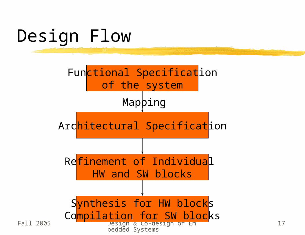
Design Flow
Functional Specificationof the system
Architectural Specification
Mapping
Refinement of Individual HW and SW blocks
Synthesis for HW blocksCompilation for SW blocks
Methodology for HW/SWCo-verification in SystemC
Processor Models
Fall 2005 Design & Co-design of Embedded Systems
19
Processor Models
Bus Functional Model (BFM)Instruction-Set Simulator (ISS)
Fall 2005 Design & Co-design of Embedded Systems
20
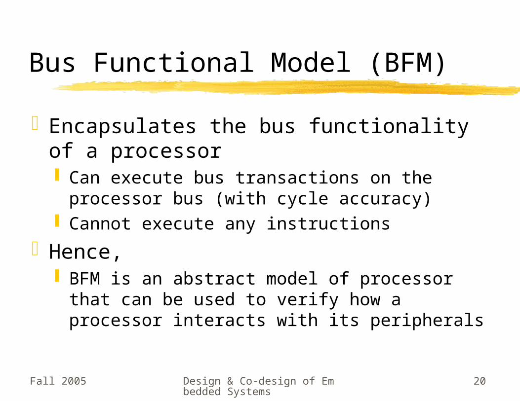
Bus Functional Model (BFM)
Encapsulates the bus functionality of a processor Can execute bus transactions on the
processor bus (with cycle accuracy) Cannot execute any instructions
Hence, BFM is an abstract model of processor that
can be used to verify how a processor interacts with its peripherals
Fall 2005 Design & Co-design of Embedded Systems
21
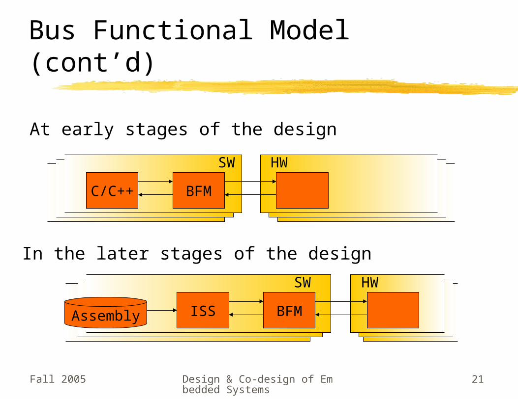
Bus Functional Model (cont’d)
SWSW HWHWHWSW
C/C++ BFM
At early stages of the design
In the later stages of the design
SWSW HWHWHWSW
ISS BFMAssembly
Fall 2005 Design & Co-design of Embedded Systems
22
Design of the BFM
Is a SystemC module Ports of the module correspond to the pins of
the processor Methods of the module provide an API
(application programming interface) for the software/ISSThey depend on the type of communication
between HW and SW
BFM functionality is modeled as a set of concurrent FSMs
Fall 2005 Design & Co-design of Embedded Systems
23
Memory-mapped IO
Peripherals are located on a portion of CPU address space
BFM provided methodsvoid bfm_read_mem(sc_address, sc_data *, int)
void bfm_write_mem(sc_address, sc_data, int)
SW (without ISS) explicitly calls these functions to access HW
When using ISS, SW calls device drivers. Device drivers are run in the ISS and at proper
time call these functions
Fall 2005 Design & Co-design of Embedded Systems
24
Interrupt-driven IO
An interrupt controller is implemented in BFM It is made sensitive to the CPU interrupt lines
In case of an interrupt, the corresponding ISR is called
ISRs are registered by these BFM methodsvoid bfm_register_handler(sc_interrupt,
void (*handler)(sc_interrupt))
Interrupts may be masked/change behavior using configuration ports
Fall 2005 Design & Co-design of Embedded Systems
25
Configuration ports,Access to internal registers
CPUs often have configuration ports for Multiple modes of operation Multiple timers/serial modes Masked interrupts etc
BFM methods to access these registersvoid bfm_read_reg(sc_register, sc_data*, int nb)
void vfm_write_reg(sc_register, sc_data, int nb)
BFM usually doesn’t model general-purpose registers of the CPU (although it can)
Fall 2005 Design & Co-design of Embedded Systems
26
Timers and Serial Ports
Normally, controllers for these timers and serial ports are implemented within BFM
They are configured using configuration ports and registers Previously mentioned functions are used
They may issue interrupts to the CPU
Fall 2005 Design & Co-design of Embedded Systems
27
Performance Estimation Functions
BFM keeps track of bus transactions Can report number of clock cycles spent for
each bus transaction Reporting can be taken after each transaction
or at the end of simulation Tracking is enabled using
void bfm_enable_tracing(int level)
level is used to define multiple levels of trackingEven debug information can be produced by the BFM
Fall 2005 Design & Co-design of Embedded Systems
28
HW/SW Synchronization
Normal BFM methods are blocking SW execution is suspended until the bus
transaction is done This essentially serialized SW and HW
executionA flag can be set in the BFM to make SW
execute in parallel with HW i.e. BFM methods return immediately
SW can wait for a specific number of clock cycles by calling void bfm_idle_cycle(int)
Fall 2005 Design & Co-design of Embedded Systems
29
Processor Model
Bus Functional Model (BFM)Instruction-Set Simulator (ISS)
Fall 2005 Design & Co-design of Embedded Systems
30
Instruction-Set Simulator
ISS: a processor model capable of simulating execution of instructions
Different types of ISS for different purposes Usage 1: Verification of applications written in
assembly-codeFor fastest speed: translate target assembly
instructions into host processor instructions• Is not cycle-accurate. Specially for pipelined and
superscalar architectures
Fall 2005 Design & Co-design of Embedded Systems
31
ISS (cont’d)
Different types of ISS … (cont’d) Usage 2: Verification of timing and interface
between system componentsUsed in conjunction with a BFMISS should be timing-accurate in this usage
• ISS often works as an emulator• For performance estimation usage, ISS is to
provide accurate cycle-counting• To have certain speed improvements, ISS should
provide necessary hooks (discussed later)
Fall 2005 Design & Co-design of Embedded Systems
32
Integrating an ISS and a BFM
ISS + BFM => complete processor modelCycle-accurate ISS + (already cycle-
accurate) BFM => cycle-accurate processor model
Typical units of an ISS Fetch, Decode, Execute Execute unit performs calls to BFM to access
memory or configuration registers Fetch unit performs calls to BFM to read
instructions
Fall 2005 Design & Co-design of Embedded Systems
33
Integrating an ISS and a BFM (cont’d)
For more complex architectures (pipelined, superscalar) Other units must be modeled
Cache, prefetch, re-order buffer, issue, …Many units may need to call BFM functions
ISS may need to provide BFM with certain memory-access functions (discussed later)
Fall 2005 Design & Co-design of Embedded Systems
34
Techniques to speedup simulation
Reduce activity on memory bus Most applications: 95% of memory traffic is
attributed to instruction and data fetches Memory access previously verified? => no need to
simulate it again during co-simulationPut instruction memory (and/or data memory) inside
ISSWhat to do for external devices accessing instr./data
memory?• BFM must be configured to recognize them and call
corresponding ISS method to access instr/data• ISS must provide the above methods• ISS must implement a memory map, where certain
addresses are directly accessed, while others through bus cycles
Fall 2005 Design & Co-design of Embedded Systems
35
Techniques to speedup simulation (cont’d)
Turn off clocks on modules All clocked components activate by
clock edgeMost of time the component is not
addressed => activation and simulation (even a limited part of each process) is wasteful => turn off clocks when not necessary
How to do it?BFM generated bus clock, only when
devices on the bus are addressed
Methodology for HW/SWCo-verification in SystemC
Implementation: 8051
Fall 2005 Design & Co-design of Embedded Systems
37
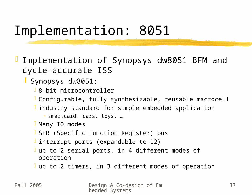
Implementation: 8051
Implementation of Synopsys dw8051 BFM and cycle-accurate ISS Synopsys dw8051:
8-bit microcontrollerConfigurable, fully synthesizable, reusable macrocellindustry standard for simple embedded application
• smartcard, cars, toys, …Many IO modesSFR (Specific Function Register) businterrupt ports (expandable to 12)up to 2 serial ports, in 4 different modes of operationup to 2 timers, in 3 different modes of operation
Fall 2005 Design & Co-design of Embedded Systems
38
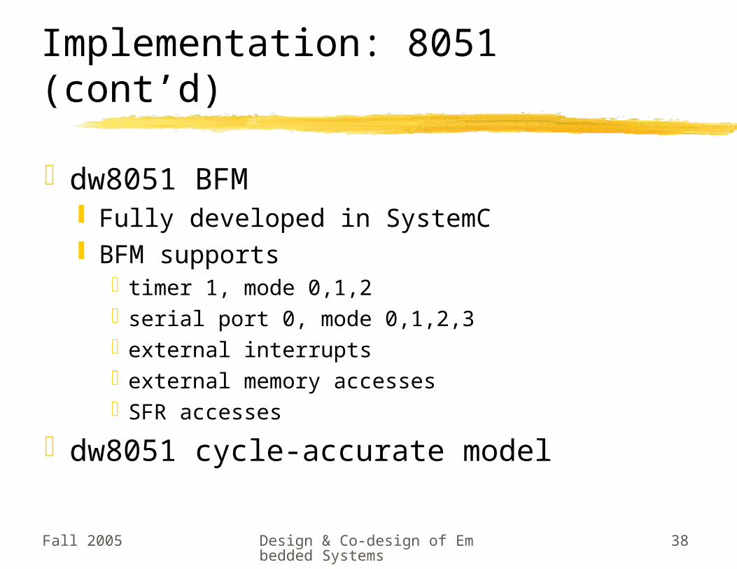
Implementation: 8051 (cont’d)
dw8051 BFM Fully developed in SystemC BFM supports
timer 1, mode 0,1,2serial port 0, mode 0,1,2,3external interruptsexternal memory accessesSFR accesses
dw8051 cycle-accurate model
Fall 2005 Design & Co-design of Embedded Systems
39
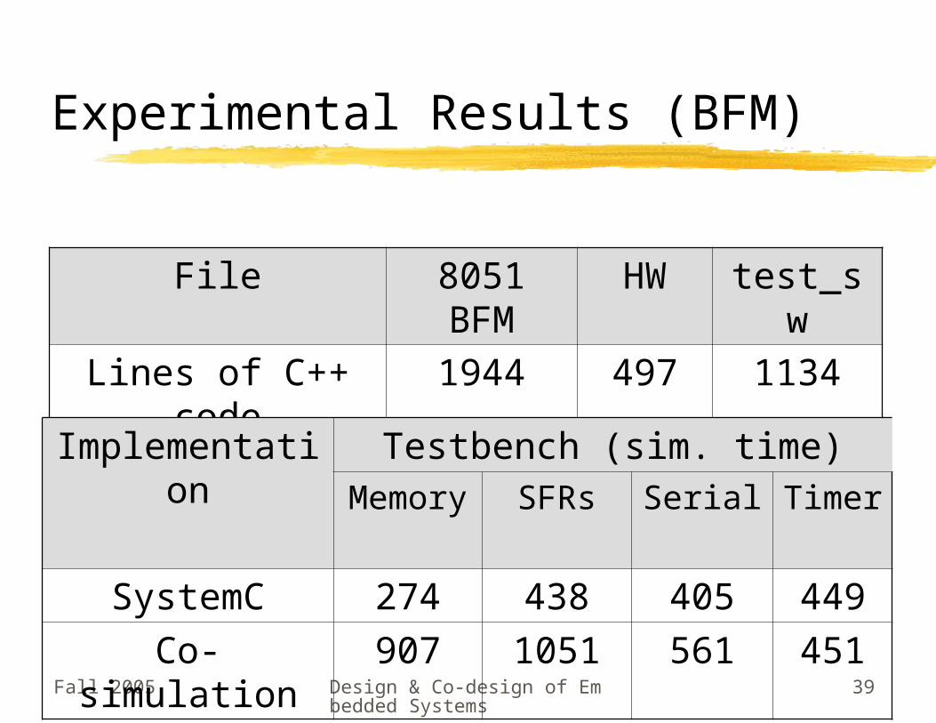
Experimental Results (BFM)
File 8051 BFM
HW test_sw
Lines of C++ code
1944 497 1134
Implementation
Testbench (sim. time)Memor
ySFRs Serial Timer
SystemC 274 438 405 449Co-simulation 907 1051 561 451
Fall 2005 Design & Co-design of Embedded Systems
40
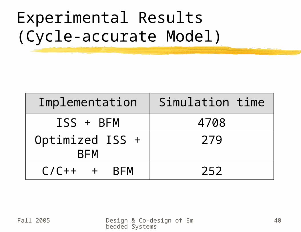
Experimental Results (Cycle-accurate Model)
Implementation Simulation timeISS + BFM 4708
Optimized ISS + BFM
279
C/C++ + BFM 252
Fall 2005 Design & Co-design of Embedded Systems
41
What we learned today
Ghosh et al co-verification strategy, using SystemC, was presented C/C++ models are very efficiently compiled on
today architectures No overhead for C-HDL interfacing is introduced Performance estimates can be obtained from
model C++ allows use of OO techniques to create BFM
and ISS, which enables re-use of them for subsequent generations of the processor