Embed Size (px)
Citation preview
1REV 0 -A - 2005281155 L-A2-459
Robert H. Peterson Co. • 14724 East Proctor Avenue • City of Industry, CA 91746 Robert H. Peterson Co. • 14724 East Proctor Avenue • City of Industry, CA 91746 Robert H. Peterson Co. • 14724 East Proctor Avenue • City of Industry, CA 91746
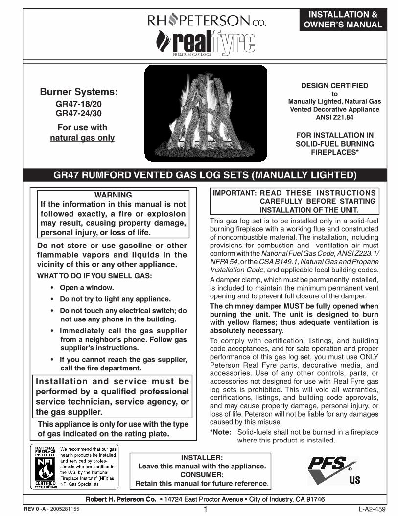
This gas log set is to be installed only in a solid-fuel burning fireplace with a working flue and constructed of noncombustible material. The installation, including provisions for combustion and ventilation air must conform with the National Fuel Gas Code, ANSI Z223.1/NFPA 54, or the CSA B149.1, Natural Gas and Propane Installation Code, and applicable local building codes.A damper clamp, which must be permanently installed, is included to maintain the minimum permanent vent opening and to prevent full closure of the damper.The chimney damper MUST be fully opened when burning the unit. The unit is designed to burn with yellow flames; thus adequate ventilation is absolutely necessary.To comply with certification, listings, and building code acceptances, and for safe operation and proper performance of this gas log set, you must use ONLY Peterson Real Fyre parts, decorative media, and accessories. Use of any other controls, parts, or accessories not designed for use with Real Fyre gas log sets is prohibited. This will void all warranties, certifications, listings, and building code approvals, and may cause property damage, personal injury, or loss of life. Peterson will not be liable for any damages caused by this misuse.*Note: Solid-fuels shall not be burned in a fireplace
where this product is installed.
IMPORTANT: READ THESE INSTRUCTIONS CAREFULLY BEFORE STARTING INSTALLATION OF THE UNIT.
Do not store or use gasoline or other flammable vapors and liquids in the vicinity of this or any other appliance.WHAT TO DO IF YOU SMELL GAS:
• Open a window.
• Do not try to light any appliance.
• Do not touch any electrical switch; do not use any phone in the building.
• Immediately call the gas supplier from a neighbor’s phone. Follow gas supplier’s instructions.
• If you cannot reach the gas supplier, call the fire department.
WARNINGIf the information in this manual is not followed exactly, a fire or explosion may result, causing property damage, personal injury, or loss of life.
This appliance is only for use with the type of gas indicated on the rating plate.
Installation and service must be performed by a qualified professional service technician, service agency, or the gas supplier.
INSTALLER:Leave this manual with the appliance.
CONSUMER:Retain this manual for future reference.
INSTALLATION & OWNER’S MANUAL
GR47 RUMFORD VENTED GAS LOG SETS (MANUALLY LIGHTED)
FOR INSTALLATION INSOLID-FUEL BURNING
FIREPLACES*
DESIGN CERTIFIEDto
Manually Lighted, Natural GasVented Decorative Appliance
ANSI Z21.84
For use withnatural gas only
Burner Systems:GR47-18/20GR47-24/30
2REV 0 -A - 2005281155 L-A2-459
TABLE OF CONTENTS
GETTING STARTEDIMPORTANT PRE-INSTALLATION AND FIREPLACE SAFETY INFORMATION ������������������������������������������������������� 3FIREPLACE OPERATING SAFETY INFORMATION ��������������������������������������������������������������������������������������������������� 4SPECIFICATIONS�������������������������������������������������������������������������������������������������������������������������������������������������������� 5DAMPER CLAMP INSTRUCTIONS ���������������������������������������������������������������������������������������������������������������������������� 7GR47 BURNER REPLACEMENT PARTS LIST ������������������������������������������������������������������������������������������������������������ 8
INSTALLATIONINSTALLATION ���������������������������������������������������������������������������������������������������������������������������������������������������������� 9
INSTALL BURNER �������������������������������������������������������������������������������������������������������������������������������������������������� 9PREPARE GRATE AND CENTER ����������������������������������������������������������������������������������������������������������������������������� 10LAVA GRANULES/COALS (optional) ������������������������������������������������������������������������������������������������������������������������ 11SAND PLACEMENT ���������������������������������������������������������������������������������������������������������������������������������������������� 12BLACK EMBERS PLACEMENT ������������������������������������������������������������������������������������������������������������������������������� 12GRATE PLACEMENT �������������������������������������������������������������������������������������������������������������������������������������������� 13LOG SET PLACEMENT������������������������������������������������������������������������������������������������������������������������������������������ 15
USE, CARE, & SERVICELIGHTING INSTRUCTIONS ������������������������������������������������������������������������������������������������������������������������������������� 16
FOR YOUR SAFETY, READ BEFORE LIGHTING ������������������������������������������������������������������������������������������������������� 16TO SHUT OFF GAS TO THE APPLIANCE ����������������������������������������������������������������������������������������������������������������� 16
CLEANING AND SERVICING ����������������������������������������������������������������������������������������������������������������������������������� 17FLAME DESCRIPTION ��������������������������������������������������������������������������������������������������������������������������������������������� 17TROUBLESHOOTING ����������������������������������������������������������������������������������������������������������������������������������������������� 18WARRANTY ������������������������������������������������������������������������������������������������������������������������������������������������������������� 20
3
IMPORTANT PRE-INSTALLATION AND FIREPLACE SAFETY INFORMATION
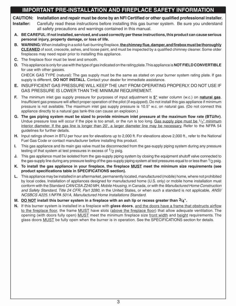
A. BE CAREFUL: If not installed, serviced, and used correctly per these instructions, this product can cause serious personal injury, property damage, or loss of life.
B. WARNING: When installing in a solid-fuel-burning fireplace, the chimney flue, damper, and firebox must be thoroughly CLEANED of soot, creosote, ashes, and loose paint, and must be inspected by a qualified chimney cleaner. Some older fireplaces may need repair prior to installing this appliance.
C. The fireplace floor must be level and smooth.D. This appliance is only for use with the type of gas indicated on the rating plate. This appliance is NOT FIELD CONVERTIBLE
for use with other gasses.CHECK GAS TYPE (natural): The gas supply must be the same as stated on your burner system rating plate. If gas supply is different, DO NOT INSTALL. Contact your dealer for immediate assistance.
E. INSUFFICIENT GAS PRESSURE WILL KEEP THE UNIT FROM OPERATING PROPERLY. DO NOT USE IF GAS PRESSURE IS LOWER THAN THE MINIMUM REQUIREMENT.
F. The minimum inlet gas supply pressure for purposes of input adjustment is 5" water column (w.c.) on natural gas. Insufficient gas pressure will affect proper operation of the pilot (if equipped). Do not install this gas appliance if minimum pressure is not available. The maximum inlet gas supply pressure is 10.5" w.c. on natural gas. (Do not connect this appliance directly to a natural gas tank-this can cause an explosion.)
G. The gas piping system must be sized to provide minimum inlet pressure at the maximum flow rate (BTU/hr). Undue pressure loss will occur if the pipe is too small, or the run is too long. Gas supply pipe must be 1/2" minimum interior diameter. If the gas line is longer than 20', a larger diameter line may be necessary. Refer to the NFPA 54 guidelines for further details.
H. Input ratings shown in BTU per hour are for elevations up to 2,000 ft. For elevations above 2,000 ft., refer to the National Fuel Gas Code or contact manufacturer before installing this product.
I. This gas appliance and its main gas valve must be disconnected from the gas-supply piping system during any pressure testing of that system at test pressures in excess of 1/2 psig.
J. This gas appliance must be isolated from the gas-supply piping system by closing the equipment shutoff valve connected to the gas-supply line during any pressure testing of the gas-supply piping system at test pressures equal to or less than 1/2 psig.
K. To install the gas appliance in your fireplace, the fireplace MUST meet the minimum size requirements (see product specifications table in SPECIFICATIONS section).
L. This appliance may be installed in an aftermarket, permanently located, manufactured (mobile) home, where not prohibited by local codes. Installation of appliances designed for manufactured home (U.S. only) or mobile home installation must conform with the Standard CAN/CSA Z240 MH, Mobile Housing, in Canada, or with the Manufactured Home Construction and Safety Standard, Title 24 CFR, Part 3280, in the United States, or when such a standard is not applicable, ANSI/NCSBCS A225.1/NFPA 501A, Manufactured Home Installations Standard.
M. DO NOT install this burner system in a fireplace with an ash lip or recess greater than 3/4".N. If this burner system is installed in a fireplace with glass doors, and the doors have a frame that obstructs airflow
to the fireplace floor, the frame MUST have slots (above the fireplace floor) that allow adequate ventilation. The opening (with doors fully open) MUST meet the minimum fireplace size front width and height requirements. The glass doors MUST be fully open when the burner is in operation. See the SPECIFICATIONS section for details.
CAUTION: Installation and repair must be done by an NFI Certified or other qualified professional installer. Installer: Carefully read these instructions before installing this gas burner system. Be sure you understand
all safety precautions and warnings contained in this manual.
GETTING STARTED
4
FIREPLACE OPERATING SAFETY INFORMATION
A. Adults shall be present when this gas appliance is operating. This unit shall not be left burning when unattended or while anyone is sleeping.
B. Keep the area of the gas burner system clear and free from combustible materials, gasoline, and other flammable vapors and liquids.
C. DO NOT use this appliance if any part has been underwater. Immediately call a qualified service technician to inspect the appliance and to replace any part of the control system and any gas control that has been underwater. Attempted operation may result in fire or explosion resulting in property damage, personal injury or loss of life.
D. A fireplace screen must be in place when the system is burning. Provisions for adequate combustion air must be maintained. Unless other provisions for combustion air are provided, the screen shall have an opening(s) for introduction of combustion air. Combustion air is adequate when all flames curl into the fireplace and away from the screen. When a glass fireplace enclosure (door) is used, the glass doors MUST be fully open when the burner is in operation.
E. Do not remove the rating plates or the warning tags. These are an integral safety and identification component of this appliance.
F. Be sure to read the CLEANING AND SERVICING and FLAME DESCRIPTION sections.
5
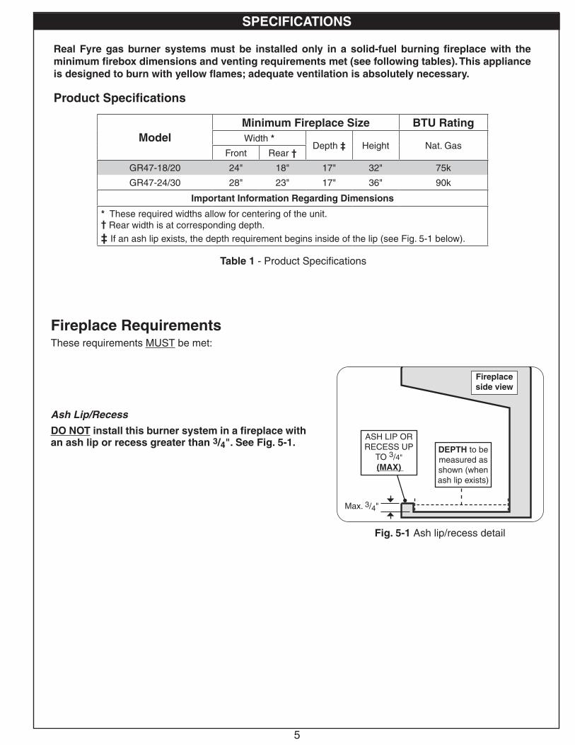
Real Fyre gas burner systems must be installed only in a solid-fuel burning fireplace with the minimum firebox dimensions and venting requirements met (see following tables). This appliance is designed to burn with yellow flames; adequate ventilation is absolutely necessary.
SPECIFICATIONS
Product Specifications
ModelMinimum Fireplace Size BTU RatingWidth *
Depth ‡ Height Nat. GasFront Rear †
GR47-18/20 24" 18" 17" 32" 75k
GR47-24/30 28" 23" 17" 36" 90k
Important Information Regarding Dimensions
* These required widths allow for centering of the unit.† Rear width is at corresponding depth.‡ If an ash lip exists, the depth requirement begins inside of the lip (see Fig. 5-1 below).
Table 1 - Product Specifications
Fireplace side view
Max. 3/4"
ASH LIP OR RECESS UP
TO 3/4"(MAX)
DEPTH to be measured as shown (when ash lip exists)
Fig. 5-1 Ash lip/recess detail
Fireplace RequirementsThese requirements MUST be met:
Ash Lip/Recess
DO NOT install this burner system in a fireplace with an ash lip or recess greater than 3/4". See Fig. 5-1.
6
SPECIFICATIONS (cont.)
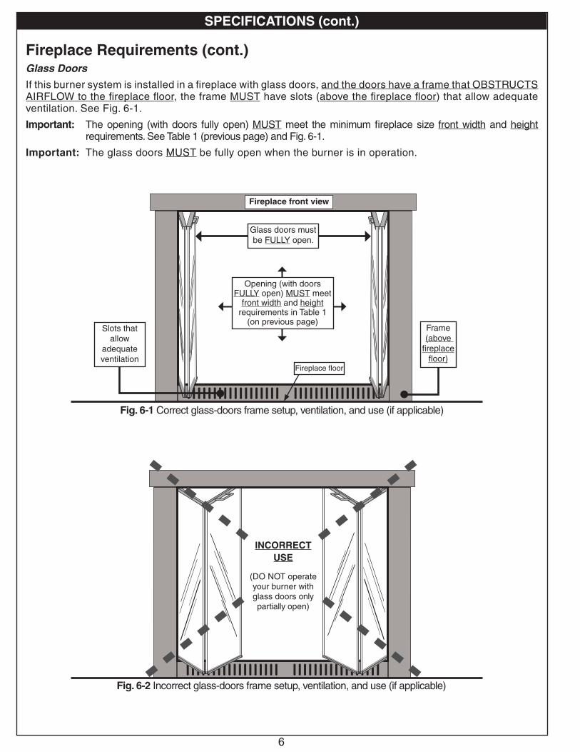
Fireplace Requirements (cont.)Glass Doors
If this burner system is installed in a fireplace with glass doors, and the doors have a frame that OBSTRUCTS AIRFLOW to the fireplace floor, the frame MUST have slots (above the fireplace floor) that allow adequate ventilation. See Fig. 6-1.
Important: The opening (with doors fully open) MUST meet the minimum fireplace size front width and height requirements. See Table 1 (previous page) and Fig. 6-1.
Important: The glass doors MUST be fully open when the burner is in operation.
Fig. 6-1 Correct glass-doors frame setup, ventilation, and use (if applicable)
Fireplace front view
Fireplace floor
Frame(above
fireplace floor)
Slots that allow
adequate ventilation
Glass doors must be FULLY open.
Opening (with doors FULLY open) MUST meet
front width and height requirements in Table 1
(on previous page)
Fig. 6-2 Incorrect glass-doors frame setup, ventilation, and use (if applicable)
INCORRECT USE
(DO NOT operate your burner with glass doors only partially open)
7
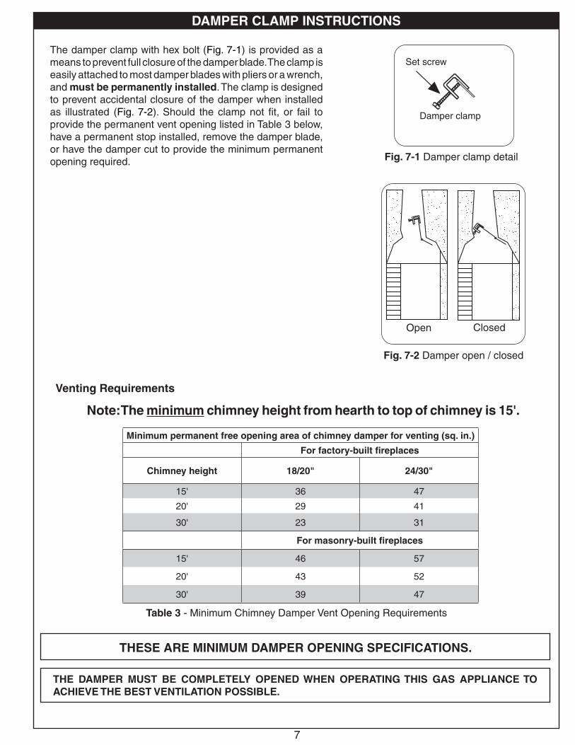
Damper clamp
Set screw
Open Closed
DAMPER CLAMP INSTRUCTIONS
Fig. 7-1 Damper clamp detail
Fig. 7-2 Damper open / closed
The damper clamp with hex bolt (Fig. 7-1) is provided as a means to prevent full closure of the damper blade. The clamp is easily attached to most damper blades with pliers or a wrench, and must be permanently installed. The clamp is designed to prevent accidental closure of the damper when installed as illustrated (Fig. 7-2). Should the clamp not fit, or fail to provide the permanent vent opening listed in Table 3 below, have a permanent stop installed, remove the damper blade, or have the damper cut to provide the minimum permanent opening required.
Note: The minimum chimney height from hearth to top of chimney is 15'.
Table 3 - Minimum Chimney Damper Vent Opening Requirements
Venting Requirements
THE DAMPER MUST BE COMPLETELY OPENED WHEN OPERATING THIS GAS APPLIANCE TO ACHIEVE THE BEST VENTILATION POSSIBLE.
THESE ARE MINIMUM DAMPER OPENING SPECIFICATIONS.
Minimum permanent free opening area of chimney damper for venting (sq. in.)
For factory-built fireplaces
Chimney height 18/20" 24/30"
15' 36 47
20' 29 41
30' 23 31
For masonry-built fireplaces
15' 46 57
20' 43 52
30' 39 47
8
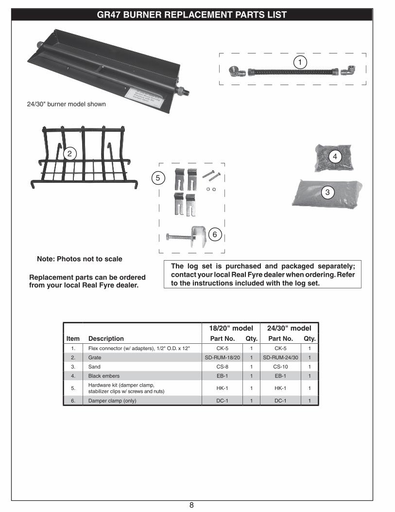
GR47 BURNER REPLACEMENT PARTS LIST
Note: Photos not to scale
Replacement parts can be ordered from your local Real Fyre dealer.
24/30" burner model shown
18/20" model 24/30" modelItem Description Part No. Qty. Part No. Qty.
1. Flex connector (w/ adapters), 1/2" O.D. x 12" CK-5 1 CK-5 1
2. Grate SD-RUM-18/20 1 SD-RUM-24/30 1
3. Sand CS-8 1 CS-10 1
4. Black embers EB-1 1 EB-1 1
5.Hardware kit (damper clamp, stabilizer clips w/ screws and nuts)
HK-1 1 HK-1 1
6. Damper clamp (only) DC-1 1 DC-1 1
The log set is purchased and packaged separately; contact your local Real Fyre dealer when ordering. Refer to the instructions included with the log set.
3
42
6
5
1
9
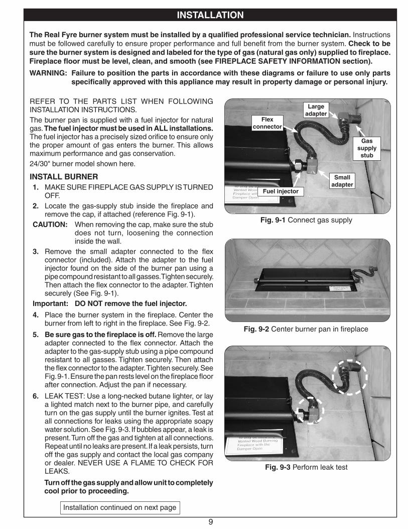
REFER TO THE PARTS LIST WHEN FOLLOWING INSTALLATION INSTRUCTIONS. The burner pan is supplied with a fuel injector for natural gas. The fuel injector must be used in ALL installations. The fuel injector has a precisely sized orifice to ensure only the proper amount of gas enters the burner. This allows maximum performance and gas conservation.24/30" burner model shown here.
INSTALL BURNER1. MAKE SURE FIREPLACE GAS SUPPLY IS TURNED
OFF.2. Locate the gas-supply stub inside the fireplace and
remove the cap, if attached (reference Fig. 9-1).CAUTION: When removing the cap, make sure the stub
does not turn, loosening the connection inside the wall.
3. Remove the small adapter connected to the flex connector (included). Attach the adapter to the fuel injector found on the side of the burner pan using a pipe compound resistant to all gasses. Tighten securely. Then attach the flex connector to the adapter. Tighten securely (See Fig. 9-1).
Important: DO NOT remove the fuel injector.
4. Place the burner system in the fireplace. Center the burner from left to right in the fireplace. See Fig. 9-2.
5. Be sure gas to the fireplace is off. Remove the large adapter connected to the flex connector. Attach the adapter to the gas-supply stub using a pipe compound resistant to all gasses. Tighten securely. Then attach the flex connector to the adapter. Tighten securely. See Fig. 9-1. Ensure the pan rests level on the fireplace floor after connection. Adjust the pan if necessary.
6. LEAK TEST: Use a long-necked butane lighter, or lay a lighted match next to the burner pipe, and carefully turn on the gas supply until the burner ignites. Test at all connections for leaks using the appropriate soapy water solution. See Fig. 9-3. If bubbles appear, a leak is present. Turn off the gas and tighten at all connections. Repeat until no leaks are present. If a leak persists, turn off the gas supply and contact the local gas company or dealer. NEVER USE A FLAME TO CHECK FOR LEAKS.
Turn off the gas supply and allow unit to completely cool prior to proceeding.
The Real Fyre burner system must be installed by a qualified professional service technician. Instructions must be followed carefully to ensure proper performance and full benefit from the burner system. Check to be sure the burner system is designed and labeled for the type of gas (natural gas only) supplied to fireplace. Fireplace floor must be level, clean, and smooth (see FIREPLACE SAFETY INFORMATION section).
WARNING: Failure to position the parts in accordance with these diagrams or failure to use only parts specifically approved with this appliance may result in property damage or personal injury.
INSTALLATION
Fig. 9-2 Center burner pan in fireplace
Fig. 9-1 Connect gas supply
Installation continued on next page
Fig. 9-3 Perform leak test
Large adapter
Gas supply stub
Small adapter
Fuel injector
Flex connector
INSTALLATION
10
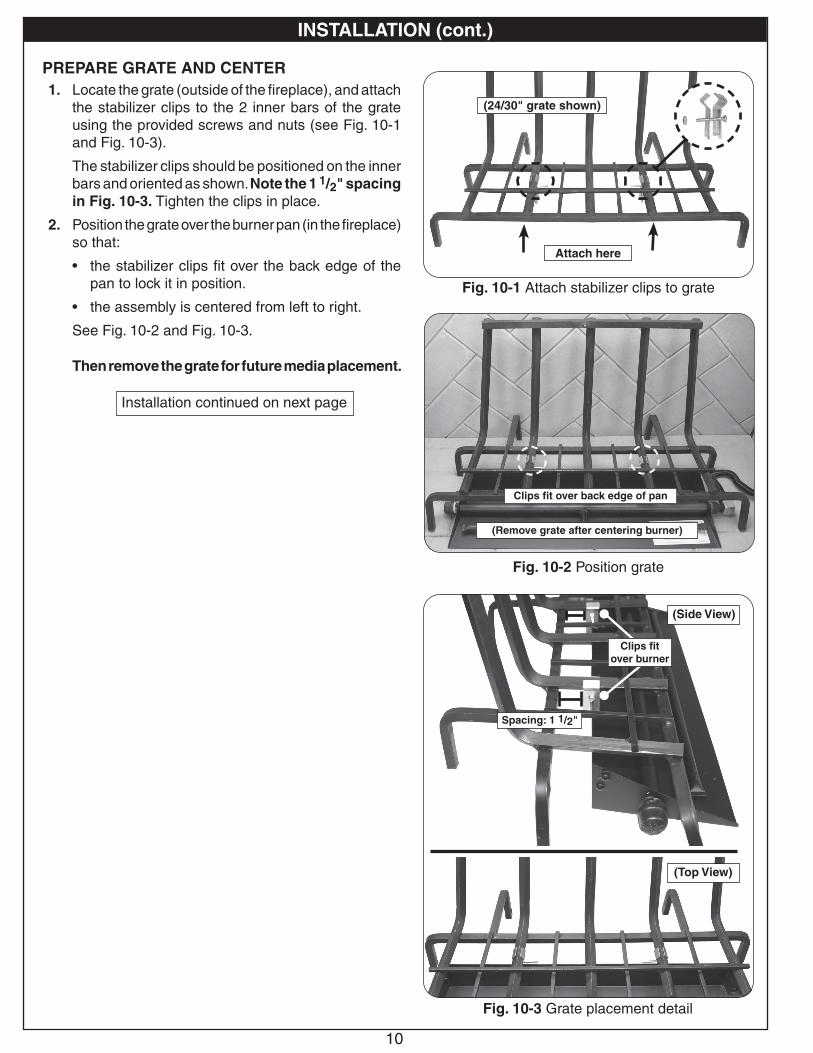
INSTALLATION (cont.)
Fig. 10-1 Attach stabilizer clips to grate
Fig. 10-2 Position grate
(24/30" grate shown)
Fig. 10-3 Grate placement detail
Installation continued on next page
PREPARE GRATE AND CENTER1. Locate the grate (outside of the fireplace), and attach
the stabilizer clips to the 2 inner bars of the grate using the provided screws and nuts (see Fig. 10-1 and Fig. 10-3).
The stabilizer clips should be positioned on the inner bars and oriented as shown. Note the 1 1/2" spacing in Fig. 10-3. Tighten the clips in place.
2. Position the grate over the burner pan (in the fireplace) so that:
• the stabilizer clips fit over the back edge of the pan to lock it in position.
• the assembly is centered from left to right.
See Fig. 10-2 and Fig. 10-3.
Then remove the grate for future media placement.
(Remove grate after centering burner)
Clips fit over back edge of pan
(Top View)
(Side View)
Spacing: 1 1/2"
Clips fit over burner
Attach here
11
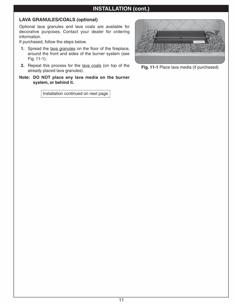
LAVA GRANULES/COALS (optional)Optional lava granules and lava coals are available for decorative purposes. Contact your dealer for ordering information.If purchased, follow the steps below.
1. Spread the lava granules on the floor of the fireplace, around the front and sides of the burner system (see Fig. 11-1).
2. Repeat this process for the lava coals (on top of the already placed lava granules).
Note: DO NOT place any lava media on the burner system, or behind it.
INSTALLATION (cont.)
Installation continued on next page
Fig. 11-1 Place lava media (if purchased)
12
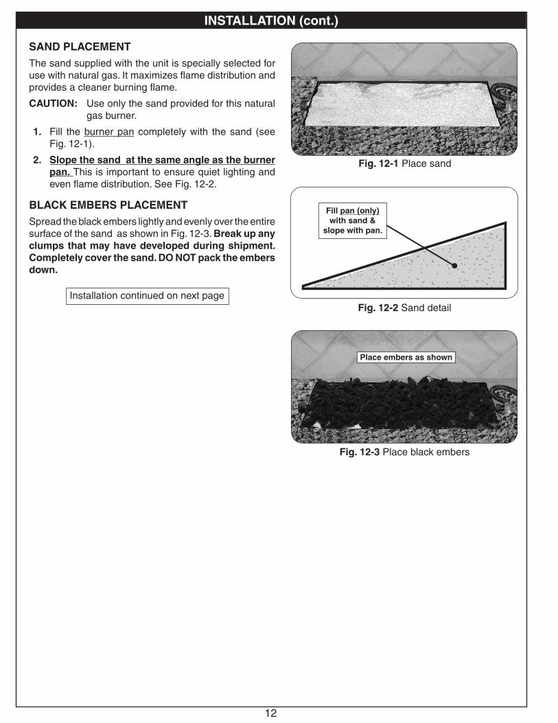
SAND PLACEMENTThe sand supplied with the unit is specially selected for use with natural gas. It maximizes flame distribution and provides a cleaner burning flame.
CAUTION: Use only the sand provided for this natural gas burner.
1. Fill the burner pan completely with the sand (see Fig. 12-1).
2. Slope the sand at the same angle as the burner pan. This is important to ensure quiet lighting and even flame distribution. See Fig. 12-2.
BLACK EMBERS PLACEMENTSpread the black embers lightly and evenly over the entire surface of the sand as shown in Fig. 12-3. Break up any clumps that may have developed during shipment. Completely cover the sand. DO NOT pack the embers down.
INSTALLATION (cont.)
Installation continued on next page
Fig. 12-3 Place black embers
Place embers as shown
Fig. 12-1 Place sand
Fig. 12-2 Sand detail
Fill pan (only) with sand &
slope with pan.
13
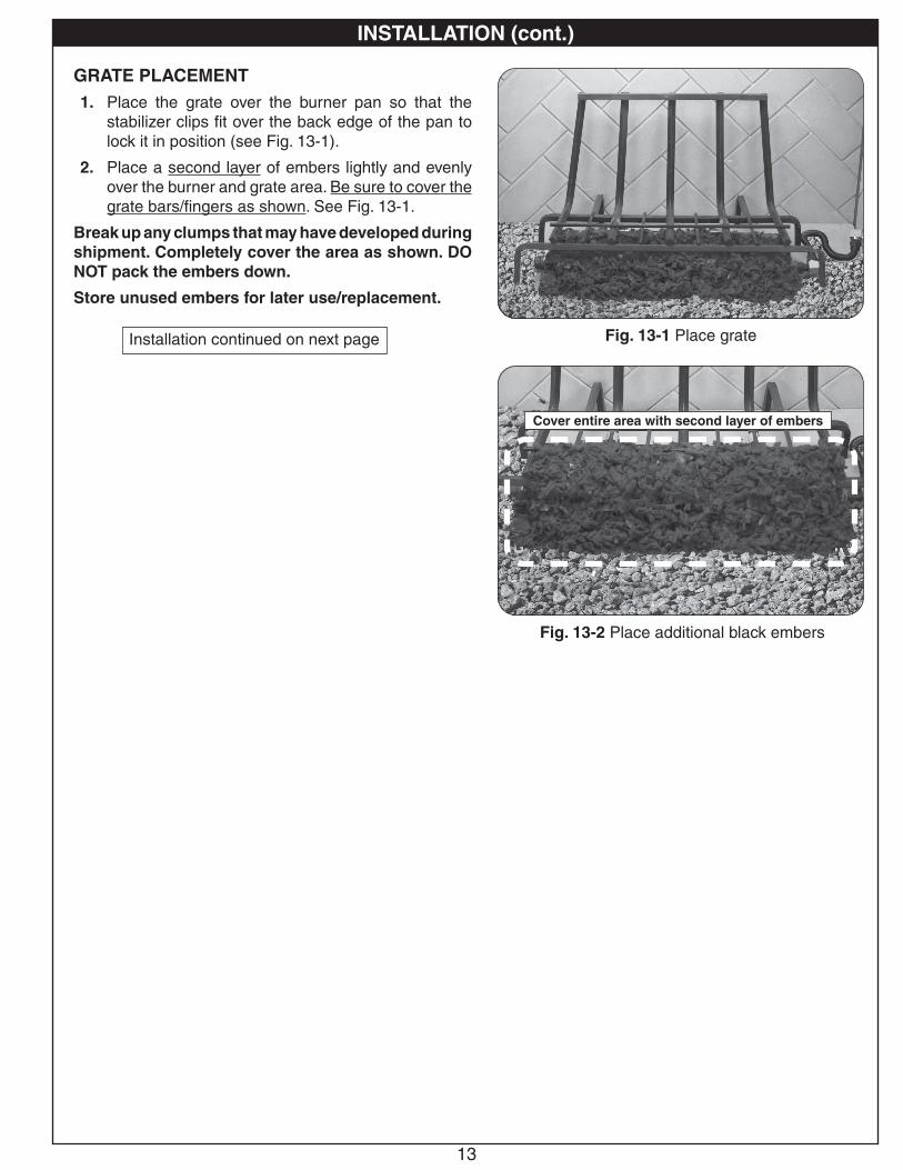
GRATE PLACEMENT1. Place the grate over the burner pan so that the
stabilizer clips fit over the back edge of the pan to lock it in position (see Fig. 13-1).
2. Place a second layer of embers lightly and evenly over the burner and grate area. Be sure to cover the grate bars/fingers as shown. See Fig. 13-1.
Break up any clumps that may have developed during shipment. Completely cover the area as shown. DO NOT pack the embers down.
Store unused embers for later use/replacement.
INSTALLATION (cont.)
Fig. 13-1 Place grateInstallation continued on next page
Fig. 13-2 Place additional black embers
Cover entire area with second layer of embers
14
INSTALLATION (cont.)
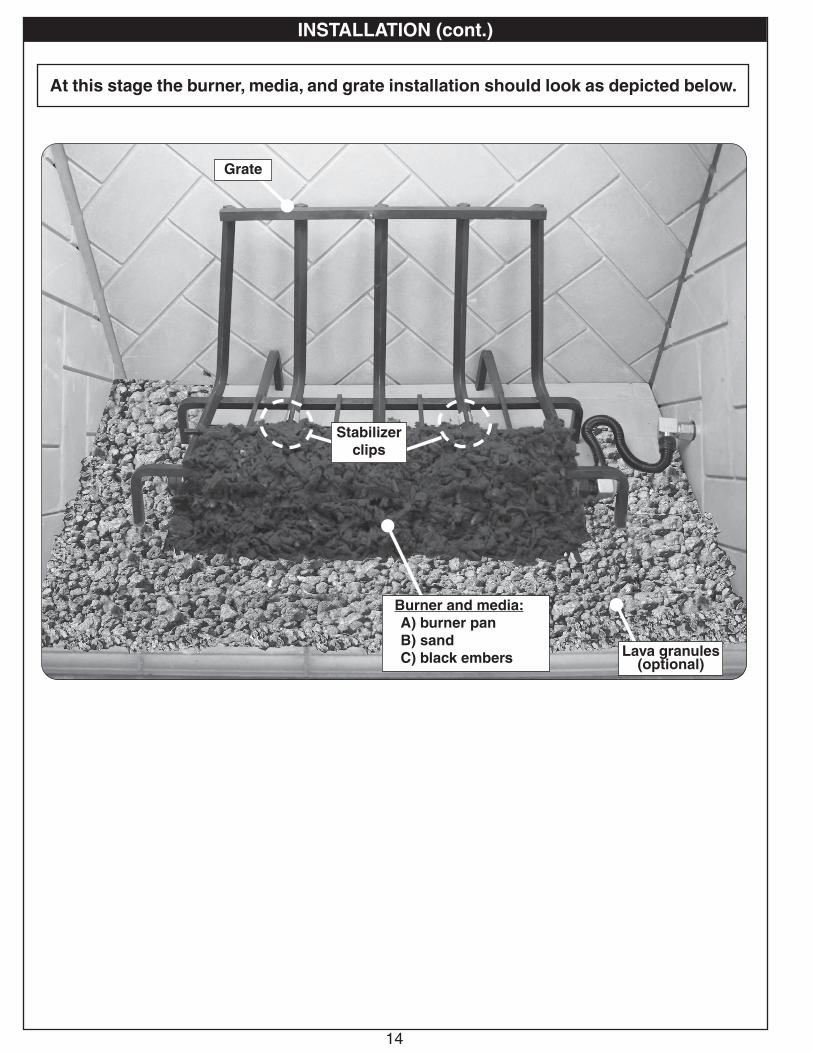
At this stage the burner, media, and grate installation should look as depicted below.
Stabilizer clips
Burner and media:A) burner panB) sandC) black embers Lava granules
(optional)
Grate
15
INSTALLATION (cont.)
CAUTION: BURN HAZARD! Logs will remain hot for some time after use. If you need to reposition any log to maintain the proper layout, use heat-resistant gloves or allow logs adequate time to cool before handling.
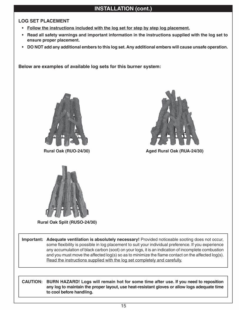
LOG SET PLACEMENT• Follow the instructions included with the log set for step by step log placement.
• Read all safety warnings and important information in the instructions supplied with the log set to ensure proper placement.
• DO NOT add any additional embers to this log set. Any additional embers will cause unsafe operation.
Below are examples of available log sets for this burner system:
Important: Adequate ventilation is absolutely necessary! Provided noticeable sooting does not occur, some flexibility is possible in log placement to suit your individual preference. If you experience any accumulation of black carbon (soot) on your logs, it is an indication of incomplete combustion and you must move the affected log(s) so as to minimize the flame contact on the affected log(s). Read the instructions supplied with the log set completely and carefully.
Rural Oak (RUO-24/30)
Rural Oak Split (RUSO-24/30)
Aged Rural Oak (RUA-24/30)
16
1. STOP! Read the safety information above.
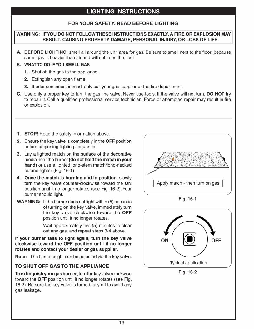
2. Ensure the key valve is completely in the OFF position before beginning lighting sequence.
3. Lay a lighted match on the surface of the decorative media near the burner (do not hold the match in your hand) or use a lighted long-stem match/long-necked butane lighter (Fig. 16-1).
4. Once the match is burning and in position, slowly turn the key valve counter-clockwise toward the ON position until it no longer rotates (see Fig. 16-2). Your burner should light.
WARNING: If the burner does not light within (5) seconds of turning on the key valve, immediately turn the key valve clockwise toward the OFF position until it no longer rotates.
Wait approximately five (5) minutes to clear out any gas, and repeat steps 3-4 above.
If your burner fails to light again, turn the key valve clockwise toward the OFF position until it no longer rotates and contact your dealer or gas supplier.
Note: The flame height can be adjusted via the key valve.
TO SHUT OFF GAS TO THE APPLIANCETo extinguish your gas burner, turn the key valve clockwise toward the OFF position until it no longer rotates (see Fig. 16-2). Be sure the key valve is turned fully off to avoid any gas leakage.
WARNING: IF YOU DO NOT FOLLOW THESE INSTRUCTIONS EXACTLY, A FIRE OR EXPLOSION MAY RESULT, CAUSING PROPERTY DAMAGE, PERSONAL INJURY, OR LOSS OF LIFE.
A. BEFORE LIGHTING, smell all around the unit area for gas. Be sure to smell next to the floor, because some gas is heavier than air and will settle on the floor.
B. WHAT TO DO IF YOU SMELL GAS
1. Shut off the gas to the appliance.
2. Extinguish any open flame.
3. If odor continues, immediately call your gas supplier or the fire department.
C. Use only a proper key to turn the gas line valve. Never use tools. If the valve will not turn, DO NOT try to repair it. Call a qualified professional service technician. Force or attempted repair may result in fire or explosion.
FOR YOUR SAFETY, READ BEFORE LIGHTING
Fig. 16-2
Fig. 16-1
Apply match - then turn on gas
LIGHTING INSTRUCTIONS
Typical application
OFFON
USE, CARE, & SERVICE
17
CLEANING AND SERVICING
Note: Discoloration is common on the grate after burning.
Note: Servicing may be necessary to ensure proper operation and burn characteristics.
Always shut off the gas to the appliance while performing service work.
Allow the appliance to cool before servicing.
Installation, service, and repair must be done by an NFI Certified or other qualified professional service technician. The appliance should be examined before use, and must be inspected at least annually to prevent burner shutdown, sooting, odors, etc. It must be checked for clean burning operation with the correct tools to service this unit. More frequent servicing may be required. It is imperative that all components and compartments, burner(s), and circulating air passageways of the appliance be kept clean and free of all obstructions (as applicable).
In addition, a periodic examination and cleaning of the fireplace venting system should be conducted by a qualified professional service technician.
Any safety screen or guard removed for servicing must be replaced prior to operating this appliance.
Verify proper operation after servicing.
If, after a period of use, the flames start to exhibit unusual shapes and behavior, or the burners fail to ignite smoothly, the burner may require cleaning or servicing. If this happens, it is recommended to contact the nearest dealer to get the appliance serviced.
DO NOT remove the rating plates or the warning tags. These are an integral safety and identification component of this appliance.
We recommend following these instructions at the beginning of each fireplace season and as needed throughout the year, depending on your usage pattern and the environmental conditions in your home.
FLAME DESCRIPTION
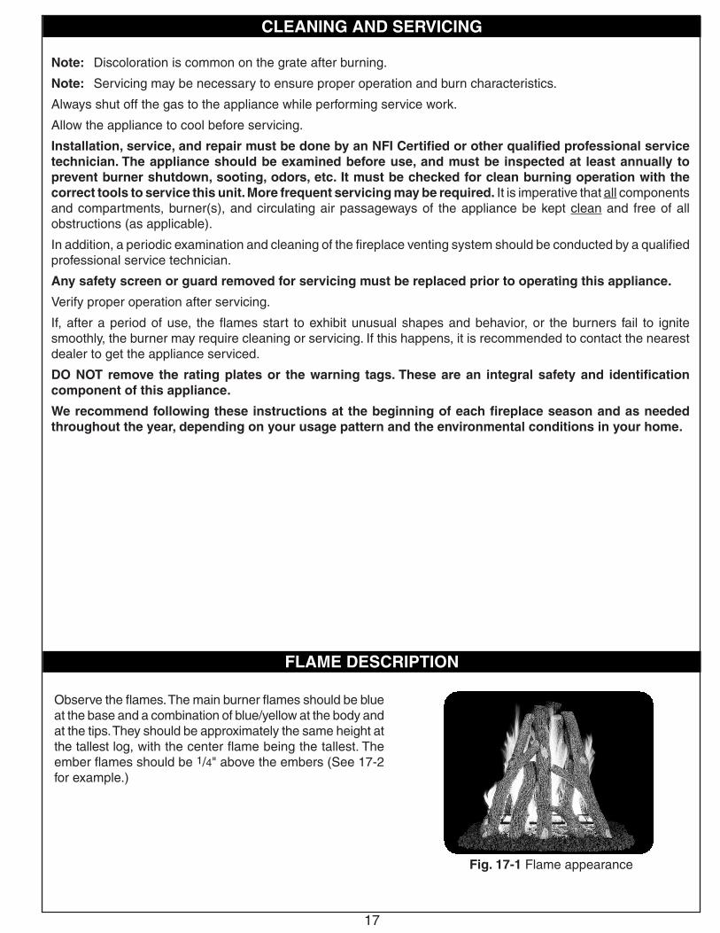
Fig. 17-1 Flame appearance
Observe the flames. The main burner flames should be blue at the base and a combination of blue/yellow at the body and at the tips. They should be approximately the same height at the tallest log, with the center flame being the tallest. The ember flames should be 1/4" above the embers (See 17-2 for example.)
18
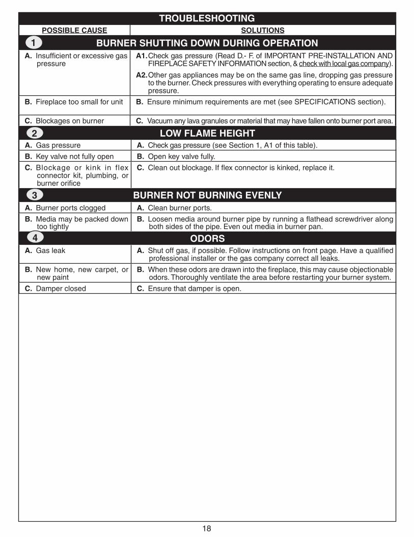
POSSIBLE CAUSE SOLUTIONS
BURNER SHUTTING DOWN DURING OPERATIONA. Insufficient or excessive gas
pressureA1. Check gas pressure (Read D.- F. of IMPORTANT PRE-INSTALLATION AND
FIREPLACE SAFETY INFORMATION section, & check with local gas company).
A2. Other gas appliances may be on the same gas line, dropping gas pressure to the burner. Check pressures with everything operating to ensure adequate pressure.
B. Fireplace too small for unit B. Ensure minimum requirements are met (see SPECIFICATIONS section).
C. Blockages on burner C. Vacuum any lava granules or material that may have fallen onto burner port area.
TROUBLESHOOTING
1
LOW FLAME HEIGHTA. Gas pressure A. Check gas pressure (see Section 1, A1 of this table).
B. Key valve not fully open B. Open key valve fully.
C. Blockage or kink in flex connector kit, plumbing, or burner orifice
C. Clean out blockage. If flex connector is kinked, replace it.
BURNER NOT BURNING EVENLYA. Burner ports clogged A. Clean burner ports.
B. Media may be packed down too tightly
B. Loosen media around burner pipe by running a flathead screwdriver along both sides of the pipe. Even out media in burner pan.
ODORSA. Gas leak A. Shut off gas, if possible. Follow instructions on front page. Have a qualified
professional installer or the gas company correct all leaks.
B. New home, new carpet, or new paint
B. When these odors are drawn into the fireplace, this may cause objectionable odors. Thoroughly ventilate the area before restarting your burner system.
C. Damper closed C. Ensure that damper is open.
2
3
4
19
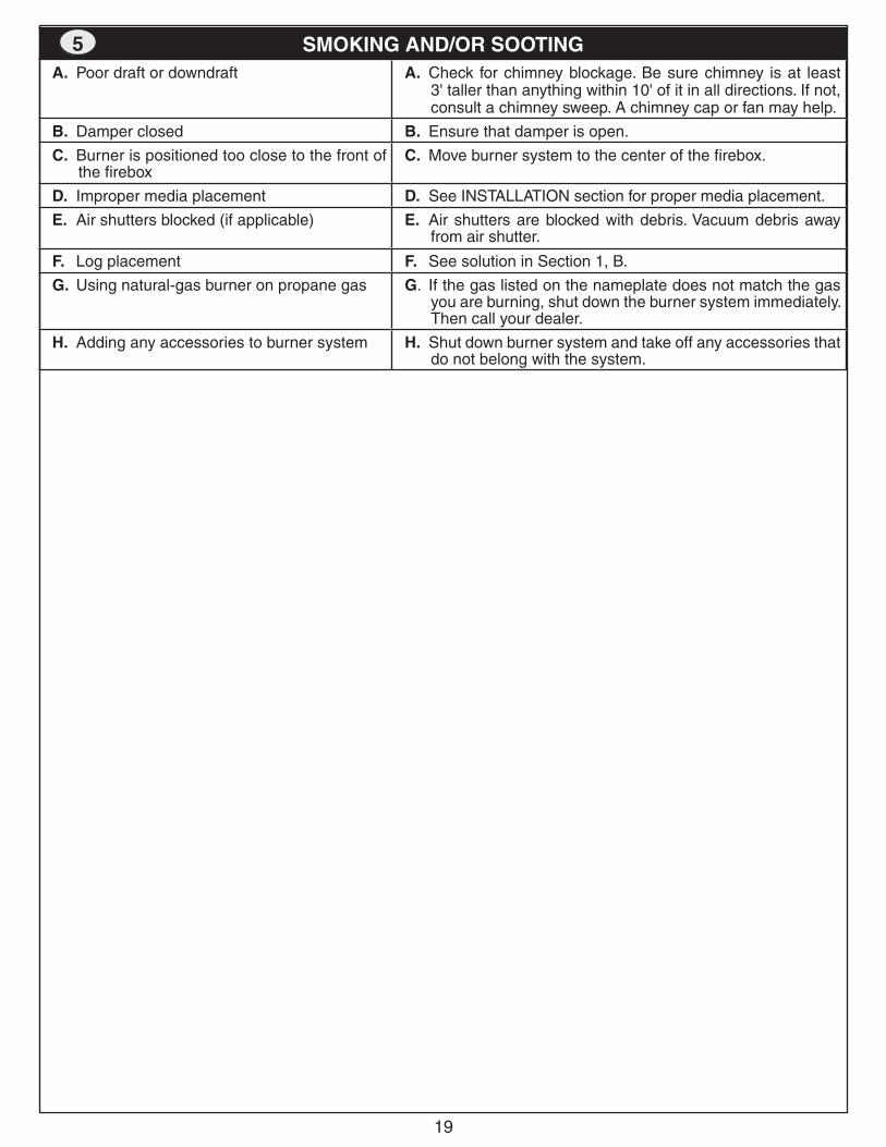
SMOKING AND/OR SOOTINGA. Poor draft or downdraft A. Check for chimney blockage. Be sure chimney is at least
3' taller than anything within 10' of it in all directions. If not, consult a chimney sweep. A chimney cap or fan may help.
B. Damper closed B. Ensure that damper is open.
C. Burner is positioned too close to the front of the firebox
C. Move burner system to the center of the firebox.
D. Improper media placement D. See INSTALLATION section for proper media placement.
E. Air shutters blocked (if applicable) E. Air shutters are blocked with debris. Vacuum debris away from air shutter.
F. Log placement F. See solution in Section 1, B.
G. Using natural-gas burner on propane gas G. If the gas listed on the nameplate does not match the gas you are burning, shut down the burner system immediately. Then call your dealer.
H. Adding any accessories to burner system H. Shut down burner system and take off any accessories that do not belong with the system.
5
20Robert H. Peterson Co. • 14724 East Proctor Avenue • City of Industry, CA 91746
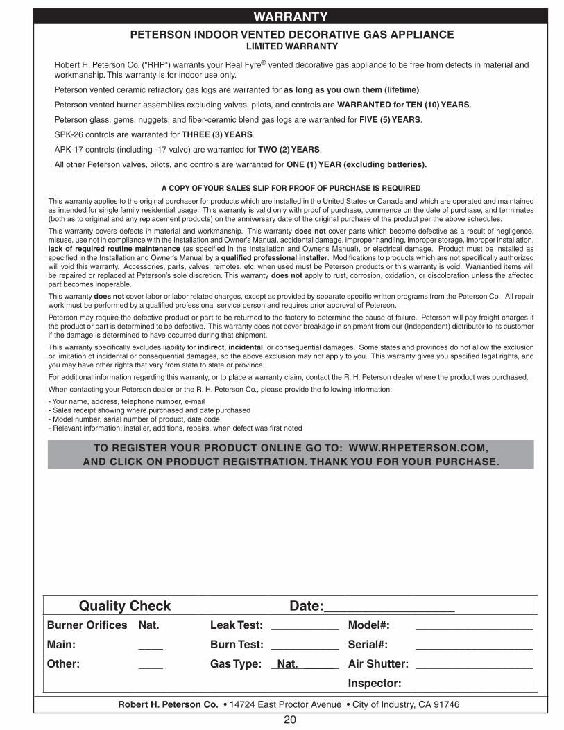
Quality Check Date:_________________Burner Orifices Nat. Leak Test: ___________ Model#: ___________________
Main: ____ Burn Test: ___________ Serial#: ___________________
Other: ____ Gas Type: Nat. _____ Air Shutter: ___________________
Inspector: ___________________
A COPY OF YOUR SALES SLIP FOR PROOF OF PURCHASE IS REQUIRED
This warranty applies to the original purchaser for products which are installed in the United States or Canada and which are operated and maintained as intended for single family residential usage. This warranty is valid only with proof of purchase, commence on the date of purchase, and terminates (both as to original and any replacement products) on the anniversary date of the original purchase of the product per the above schedules.
This warranty covers defects in material and workmanship. This warranty does not cover parts which become defective as a result of negligence, misuse, use not in compliance with the Installation and Owner’s Manual, accidental damage, improper handling, improper storage, improper installation, lack of required routine maintenance (as specified in the Installation and Owner’s Manual), or electrical damage. Product must be installed as specified in the Installation and Owner’s Manual by a qualified professional installer. Modifications to products which are not specifically authorized will void this warranty. Accessories, parts, valves, remotes, etc. when used must be Peterson products or this warranty is void. Warrantied items will be repaired or replaced at Peterson’s sole discretion. This warranty does not apply to rust, corrosion, oxidation, or discoloration unless the affected part becomes inoperable.
This warranty does not cover labor or labor related charges, except as provided by separate specific written programs from the Peterson Co. All repair work must be performed by a qualified professional service person and requires prior approval of Peterson.
Peterson may require the defective product or part to be returned to the factory to determine the cause of failure. Peterson will pay freight charges if the product or part is determined to be defective. This warranty does not cover breakage in shipment from our (Independent) distributor to its customer if the damage is determined to have occurred during that shipment.
This warranty specifically excludes liability for indirect, incidental, or consequential damages. Some states and provinces do not allow the exclusion or limitation of incidental or consequential damages, so the above exclusion may not apply to you. This warranty gives you specified legal rights, and you may have other rights that vary from state to state or province.
For additional information regarding this warranty, or to place a warranty claim, contact the R. H. Peterson dealer where the product was purchased.
When contacting your Peterson dealer or the R. H. Peterson Co., please provide the following information:
- Your name, address, telephone number, e-mail- Sales receipt showing where purchased and date purchased- Model number, serial number of product, date code- Relevant information: installer, additions, repairs, when defect was first noted
TO REGISTER YOUR PRODUCT ONLINE GO TO: WWW.RHPETERSON.COM,AND CLICK ON PRODUCT REGISTRATION. THANK YOU FOR YOUR PURCHASE.
PETERSON INDOOR VENTED DECORATIVE GAS APPLIANCELIMITED WARRANTY
Robert H. Peterson Co. ("RHP") warrants your Real Fyre® vented decorative gas appliance to be free from defects in material and workmanship. This warranty is for indoor use only.
Peterson vented ceramic refractory gas logs are warranted for as long as you own them (lifetime).
Peterson vented burner assemblies excluding valves, pilots, and controls are WARRANTED for TEN (10) YEARS.
Peterson glass, gems, nuggets, and fiber-ceramic blend gas logs are warranted for FIVE (5) YEARS.
SPK-26 controls are warranted for THREE (3) YEARS.
APK-17 controls (including -17 valve) are warranted for TWO (2) YEARS.
All other Peterson valves, pilots, and controls are warranted for ONE (1) YEAR (excluding batteries).
WARRANTY