Embed Size (px)
Citation preview

Version 2011 © European Aluminium Association ([email protected]) 1
Design – Case study: Bonnet and boot lid Table of contents 6 Case study: Bonnet and boot lid .................................................................................................. 2
6.1 Introduction ........................................................................................................................ 2 6.1.1 Purpose of a Bonnet system ........................................................................................... 2 6.1.2 Purpose of a Boot lid ..................................................................................................... 3
6.2 Design Aspects ................................................................................................................... 3 6.2.1 Design Boundary Conditions for Bonnet and Boot Lid ..................................................... 3 6.2.2 Requirements for Bonnet components ............................................................................ 8 6.2.3 Prioritisation Matrix for Outer Skin Panel ..................................................................... 10 6.2.4 Conclusions: ............................................................................................................... 17 6.2.5 Overall conclusions of concept evaluation ..................................................................... 20 6.2.6 Comparison of “state of the art” systems ....................................................................... 21
6.3 Conclusions from bonnet and boot lid case study ................................................................. 25

Version 2011 © European Aluminium Association ([email protected]) 2
6 Case study: Bonnet and boot lid
6.1 Introduction Bonnet and Boot lid form a sub-segment of vehicle “closures”, which also contains doors and tail gate. Bonnet and boot lid usually do not directly open onto the passenger cell which greatly reduces the importance (weighting) of certain of the functional requirements normally associated with closures such as passenger safety, air tightness, low cycle fatigue strength etc. Legislation for new vehicle registrations in Europe, the United States of America and Japan all include requirements for pedestrian safety. EuroNCAP (European New Car Assessment Program) and other independent vehicle assessment bodies have been instrumental in increasing public awareness of the effectiveness of design for pedestrian safety. Additionally, their test results are factored into the insurance ratings that are delivered for new vehicles. The objective of these measures is to reduce the number of road accident fatalities and the severity of injuries sustained by pedestrians involved in a collision with a vehicle in urban traffic. Impact frequency and seriousness of injury has been studied for many years, resulting in rating systems and improved design. One such study based on 246 passenger car / pedestrian collisions (Bosch Automotive Handbook 4th Edition 1998) clearly shows that the bonnet zone accounts for a substantial proportion of the risk associated with pedestrian safety.
This is the major difference between bonnet and boot lid safety functional requirements. Bonnet and boot lid systems influence the following performance measures:
Overall vehicle mass Fore / aft weight distribution Height of vehicle centre of gravity (the bonnet and the boot lid are usually located
above the C of G of the vehicle, hence weight reduction is beneficial) Vehicle drive-by noise intensity.
6.1.1 Purpose of a Bonnet system The bonnet system is an access panel to the engine compartment to enable maintenance of power train, drive belts, battery, fluid levels and lamp units. It is fundamentally a reinforced skin panel with many safety and quality requirements.

Version 2011 © European Aluminium Association ([email protected]) 3
6.1.2 Purpose of a Boot lid The boot lid system is an access panel to a rear storage compartment often enabling access to auxiliary systems such as spare wheel, tool box, jack and rear light units. It is fundamentally an opening reinforced skin panel.
6.2 Design Aspects
6.2.1 Design Boundary Conditions for Bonnet and Boot Lid The boundary conditions for commencing a new design process using aluminium can be identified and analysed by grouping together requirements using affinity matrix methods. Bonnet and boot lid are treated separately and are then compared to highlight major differences.
Vehicle quality Occupant Safety
Pedestrian Safety
Torsional Stiffness Frontal CrashCollapse
Noise Attenuation
Child Head Impact Criterion
Low mass(Ease of opening)
Frontal CrashMaintain integrity with hinges etc.
Bonnet Leading Edge geometry
Flutter Resistance (Bending stiffness)
Adult Head Impact Criterion
Corrosion Resistance
Bonnet (Hood)
Dent Resistance(Palm Print)
Dent Resistance(Hail Stone and
Stone Chip)
Styling
Tight radii on hemmed panel
edges
Excellent painted surface quality
Stretch Flanges
Good Shape: Low strain doubly curved
surfaces
Frontal CrashRetention of loosed
components
Manufacturing
Paint drain features
Outer panelDent resistance during assembly
Outer panelClean sheared
edges
Outer panelNo Lüder lines or
other visual defects resulting from stretch forming
Inner panelGauling resistance
Low massWeight distribution
Low massVehicle Centre of
Gravity

Version 2011 © European Aluminium Association ([email protected]) 4
Vehicle quality Occupant Safety
Torsional Stiffness RearCrashCollapse
Low mass(Ease of opening)
Corrosion Resistance
General
Dent Resistance(Palm Print)
Styling
Tight radii on hemmed panel
edges
Excellent surface quality
Stretch Flanges
Good Shape: Low strain doubly curved
surfaces
Manufacturing
Paint drain features
Outer panelDent resistance during assembly
Outer panelClean sheared
edges
Boot (Trunk lid)
Corrosion resistance
Seal Surface
Corrosion resistance
Cut edges & holes
Auxilliary
Electrical resistanceLighting earth return
Outer panelNo Lüder lines or
other visual defects resulting from stretch forming
Inner panelGauling resistance
Low massVehicle Centre of
Gravity
Vehicle quality
Occupant Safety
Pedestrian Safety
Torsional Stiffness Frontal CrashCollapse
Noise Attenuation
Child Head Impact Criterion
Low mass(Ease of opening)
Frontal CrashMaintain integrity with hinges etc.
Bonnet Leading Edge geometry
Flutter Resistance (Bending stiffness)
Adult Head Impact Criterion
Corrosion Resistance
Bonnet (Hood)
Dent Resistance(Palm Print)
Dent Resistance(Hail Stone and
Stone Chip)
Styling
Tight radii on hemmed panel
edges
Excellent painted surface quality
Stretch Flanges
Good Shape: Low strain doubly
curved surfaces
Frontal CrashRetention of
loosed components
Manufacturing
Paint drain features
Outer panelDent resistance during assembly
Outer panelClean sheared
edges
Outer panelNo Lüder lines or
other visual defects resulting
from stretch forming
Inner panelGauling resistance
Low massWeight distribution
Low massVehicle Centre of
Gravity
Vehicle quality
Occupant Safety
Torsional Stiffness RearCrashCollapse
Low mass(Ease of opening)
Corrosion Resistance
General
Dent Resistance(Palm Print)
Styling
Tight radii on hemmed panel
edges
Excellent surface quality
Stretch Flanges
Good Shape: Low strain doubly
curved surfaces
Manufacturing
Paint drain features
Outer panelDent resistance during assembly
Outer panelClean sheared
edges
Boot (Trunk lid)
Corrosion resistance
Seal Surface
Corrosion resistance
Cut edges & holes
Auxilliary
Electrical resistance
Lighting earth return
Outer panelNo Lüder lines or
other visual defects resulting
from stretch forming
Inner panelGauling resistance
Low massVehicle Centre of
Gravity
Main functional differences between Bonnet and Boot Lid

Version 2011 © European Aluminium Association ([email protected]) 5
Main conclusions from affinity matrix analysis:
The bonnet has more safety (pedestrian and passenger) and vehicle quality (manufacturing and in-service performance) requirements than the boot lid.
An aluminium bonnet may improve fore / aft weight distribution Both seem to have similar manufacturing boundary conditions
From this point onwards we will just focus on the bonnet system. Design options assessment Aluminium enjoys the advantage of being available in a wide range of product forms that may closely represent the output from topological optimisation tools. Each product form possibility may be combined with the intrinsic properties of aluminium in order to identify the most suitable design space for this application. Herring-bone diagrams are a good way to start to develop a Design Failure Modes and Effects Analysis (DFMEA). They are also a good starting point for identification of the key design requirements, wishes and constraints in order to assist the selection of candidate materials, product forms and assembly methods, etc.
Potential solutions
Outer panel6xxx
Laminated 6/7XXXSheet Steel
Inner panel5xxx6xxx
Laminated 5/5/7XXX
High performance Plastic /
CompositesThin-walled Casting
Sheet Steel
Bonnet (Hood)
Elastic limit
Shape Characteristics
Low density
Corrosion resistance
N-value
R-value
Material Characteristics
Swages
Manufacturing
Tooling cost
Stamping
Face Spot Welds
Finishing
Section collapse Initiation features« Bird Beak »
Self Pierce Rivet
Cycle Time
Paint Bake Response
Hem f lange capabilities
Flanged holes
Anti-f lutter mastic
Total elongation
Electro Coating
PaintingSurface Roughness
Conversion coating
Lubricated and non-lubricated f riction co-ef ficients
Blanking & punching
Stretched Skin
Drawn inner panel
Flanged panel edges
Rope hem f langed upper edge skin panel
Flat hem f langed front edges skin panel
Stretcher Strain defects
Surface hardness
Fatigue resistance
Adhesive bonding
Surface quality post forming
Desired characteristics and manufacturing techniques arranged in a herring-bone diagram.
Whole vehicle system considerations Pedestrian impact energy is absorbed by a sequence of different mechanisms. In most cases, the leg of the pedestrian is first impacted by the bumper system (lower leg impact is a safety critical load case for the pedestrian that is entirely managed by the bumper system). Initial contact with the pedestrian is therefore at a point below the centre of gravity of the head and torso causing rotation. At relatively low velocity impacts (<= 40km/h) the tendency is for the head to impact the bonnet or the lower part of the windscreen.

Version 2011 © European Aluminium Association ([email protected]) 6
The height, weight and age of the pedestrian all play a role in the kinematics of the event and in his ability to survive. Most fatalities for the younger population are related to brain damage caused by head impact on the bonnet. For older people additional risks include rupture of arteries in the lower limbs and pelvis from bumper and bonnet leading edges. All major insurance and regulating authorities have studied this topic in order to put in place a range of measures to reduce mortality rates and the severity of injury resulting from pedestrian impacts. These studies have produced test procedures and systems to rank and regulate vehicles for pedestrian safety.
Evaluation of pedestrian safety for a bonnet must be carried out in the context of its surrounding elements:
Vehicle styling, size (wrap around distance “WAD”) and under bonnet clearance to other elements (considered as hard points).
Local bonnet stiffness is influenced by mounting point stiffness such as hinges, bump stops and latches.
This is better understood by superimposing the kinematics of a dummy onto the test conditions.

Version 2011 © European Aluminium Association ([email protected]) 7
Source: Institut für Kraftfahrzeuge, RWTH Aachen University, Dr J Bovenkerk
Version 2011 © European Aluminium Association ([email protected]) 8
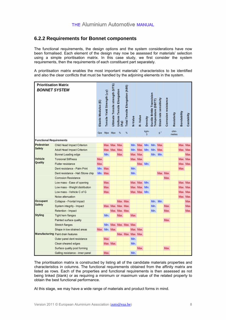
6.2.2 Requirements for Bonnet components The functional requirements, the design options and the system considerations have now been formalised. Each element of the design may now be assessed for materials’ selection using a simple prioritisation matrix. In this case study, we first consider the system requirements, then the requirements of each constituent part separately. A prioritisation matrix enables the most important materials’ characteristics to be identified and also the clear conflicts that must be handled by the adjoining elements in the system.
Gpa Mpa Mpa % %kgm-
3 S-1 ohm-metres
Child Head Impact Criterion Max. Max. Max. Min. Max. Min. Min. Max. Max. Max.
Adult Head Impact Criterion Max. Max. Max. Min. Max. Min. Min. Max. Max. Max.
Bonnet Leading edge Min. Max. Max. Max. Min. Min. Max.
Torsional Stiffness Max. Max. Max. Max. Max.
Flutter resistance Max. Max. Min. Max. Max.
Dent resistance - Palm Print Min. Max. Min. Max.
Dent resistance - Hail /Stone chip Min. Max. Min. Max. Max.
Corrosion Resistance Max.
Low mass - Ease of opening Max. Max. Max. Min. Max. Max.
Low mass - Weight distribution Max. Max. Max. Min. Max. Max.
Low mass - Vehicle C of G Max. Max. Max. Min. Max. Max.
Noise attenuation Max. Max.
Collapse - Frontal Impact Max. Max. Min. Min. Max.
System integrity - Impact Max. Max. Max. Max. Min. Max. Max.
Retention - Impact Max. Max. Max. Min. Max. Max.
Tight hem flanges Min. Max. Max.
Painted surface quality Max.
Stretch flanges Min. Max. Max. Max. Max.
Shape in low strained areas Max. Min. Max. Max. Max.
Paint drain features Max. Max. Max. Max.
Outer panel dent resistance Max. Min.
Clean sheared edges Max. Max. Min.
Surface quality post forming Max. Max.
Galling resistance - inner panel Max. Min.
Manufacturing
Occupant Safety
Vehicle Quality
Pedestrian Safety
Styling
N-V
alu
e
R-
Va
lue
De
ns
ity
Functional Requirements
Bo
nd
ab
ility
Ca
sta
bilt
y
Du
cti
le B
ritt
le T
ran
sis
ion
T
em
pe
ratu
re (
DB
TT
)
Str
ain
ra
te s
en
sit
ivit
y
Co
rro
sio
n r
es
ista
nc
e
To
tal T
en
sile
Elo
ng
ati
on
(A
80
)Prioritisation Matrix
BONNET SYSTEM
Re
sis
tiv
ity
Ela
sti
c M
od
ulu
s (
E)
Te
ns
ile Y
ield
Str
en
gth
(
y)
Ult
ima
te T
en
sile
str
en
gth
(U
TS
)
Un
ifo
rm T
en
sile
Elo
ng
ati
on
(A
g)
The prioritisation matrix is constructed by listing all of the candidate materials properties and characteristics in columns. The functional requirements obtained from the affinity matrix are listed as rows. Each of the properties and functional requirements is then assessed as not being linked (blank) or as requiring a minimum or maximum value of the related property to obtain the best functional performance. At this stage, we may have a wide range of materials and product forms in mind.
Version 2011 © European Aluminium Association ([email protected]) 9
Some parameters such as ‘r’ and ‘n’ value may enable deeper sections or tighter features to be stamped into sheet material. If extra depth is feasible from the packaging constraints, then these columns may well influence torsional stiffness and head impact performance, in which case, a maximum value is desired, but if packaging is limited, then these parameters may not be considered linked for such a stamping. DBTT can be a serious problem for certain grades of steel undergoing large deformation at low temperature. Since our main focus here is on designing with aluminium, this column can be ignored. In this case the resistivity column is totally blank. The judgement (or result of experience / analysis or test) indicates that this property does not apply for the load cases or product requirements that have been identified for this part. Blank columns may be collapsed to enable other conclusions to be obtained.

Version 2011 © European Aluminium Association ([email protected]) 10
6.2.3 Prioritisation Matrix for Outer Skin Panel The outer skins of the bonnet and boot lid are very shallow, doubly curved shell surfaces. The stiffness behaviour of the unsupported areas of theses panels to loading is dominated by their elastic modulus and thickness. Flat sheet "Oil Canning" stiffness ~ E * t2
Flat sheet bending / buckling stiffness ~ E * t3
Out of plane sheet stiffness from the above relationships is not high enough to provide useful energy absorption for head impact.
Most of the initial phase of impact energy absorption from a pedestrian head form is delivered through dynamic effects. A second phase includes more complex effects as time progresses such as panel buckling, stress stiffening of the panel in tension and engagement of the inner panel. Transient dynamic Finite Element analysis techniques are used to model the complex interactions between a validated head-form model and bonnet system. However, some basic principles can be derived from simple mechanics that is helpful in understanding why aluminium hoods are so effective for pedestrian protection. Phase I A well known criterion (HIC - Head Injury Criterion), is used to study the relationship between head impact severity and the probability of injury. HIC takes into account the progression of the resultant head acceleration curve with time. It is used to evaluate the pedestrian protection performance of vehicles.
Version 2011 © European Aluminium Association ([email protected]) 11
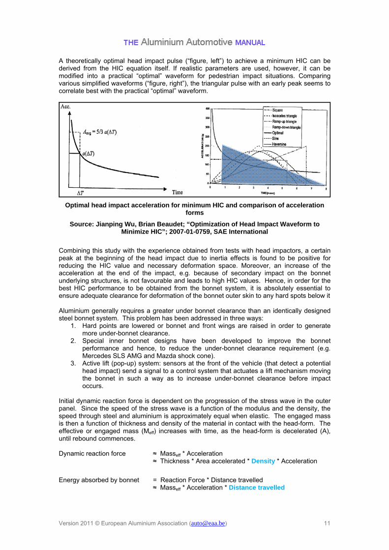
A theoretically optimal head impact pulse (“figure, left”) to achieve a minimum HIC can be derived from the HIC equation itself. If realistic parameters are used, however, it can be modified into a practical “optimal” waveform for pedestrian impact situations. Comparing various simplified waveforms (“figure, right”), the triangular pulse with an early peak seems to correlate best with the practical “optimal” waveform.
Optimal head impact acceleration for minimum HIC and comparison of acceleration forms
Source: Jianping Wu, Brian Beaudet; “Optimization of Head Impact Waveform to Minimize HIC”; 2007-01-0759, SAE International
Combining this study with the experience obtained from tests with head impactors, a certain peak at the beginning of the head impact due to inertia effects is found to be positive for reducing the HIC value and necessary deformation space. Moreover, an increase of the acceleration at the end of the impact, e.g. because of secondary impact on the bonnet underlying structures, is not favourable and leads to high HIC values. Hence, in order for the best HIC performance to be obtained from the bonnet system, it is absolutely essential to ensure adequate clearance for deformation of the bonnet outer skin to any hard spots below it Aluminium generally requires a greater under bonnet clearance than an identically designed steel bonnet system. This problem has been addressed in three ways:
1. Hard points are lowered or bonnet and front wings are raised in order to generate more under-bonnet clearance.
2. Special inner bonnet designs have been developed to improve the bonnet performance and hence, to reduce the under-bonnet clearance requirement (e.g. Mercedes SLS AMG and Mazda shock cone).
3. Active lift (pop-up) system: sensors at the front of the vehicle (that detect a potential head impact) send a signal to a control system that actuates a lift mechanism moving the bonnet in such a way as to increase under-bonnet clearance before impact occurs.
Initial dynamic reaction force is dependent on the progression of the stress wave in the outer panel. Since the speed of the stress wave is a function of the modulus and the density, the speed through steel and aluminium is approximately equal when elastic. The engaged mass is then a function of thickness and density of the material in contact with the head-form. The effective or engaged mass (Meff) increases with time, as the head-form is decelerated (A), until rebound commences. Dynamic reaction force ≈ Masseff * Acceleration ≈ Thickness * Area accelerated * Density * Acceleration
Energy absorbed by bonnet = Reaction Force * Distance travelled ≈ Masseff * Acceleration * Distance travelled

Version 2011 © European Aluminium Association ([email protected]) 12
Phase II One of the interesting properties of aluminium is its low elastic modulus. This property can be very useful if it delays the onset of plastic deformation which has a much lower tangent modulus than elastic deformation. When the impacted area of the outer panel starts to stretch locally, the ratio of elastic to plastic strain plays an important role in the reaction force generated and hence the energy absorbed. Overall bonnet stiffness is derived from the inner and outer panels and their local reinforcements and hinges. Considering the bonnet alone, the inner panel contributes most to the stiffness from its section properties. The Mercedes SLS AMG demonstrates well the high pressure differential that can be seen on long bonnets. They have succeeded in limiting the deformation to a smooth band toward the rear third of the bonnet.
Mercedes SLS AMG - Role of stiffness when subjected to air pressure loading
Source: Aachen Body Engineering Days 2009: Carsten Pech - Daimler AG
Other factors specific to aluminium Hemming Hemming is routinely carried out in aluminium and steel bonnet manufacture. Specially prepared versions of standard automotive alloys are used for panels requiring flat hemming (bonnets, boot lids and doors).

Version 2011 © European Aluminium Association ([email protected]) 13
The outer and inner panels of the bonnet and boot lid are typically attached together using a hemming operation at the edges. The front and upper edges are always hemmed by folding the outer panel around the inner panel. For the left and right edges design solutions exist where the inner panel is folded around the outer panel. During hemming the outer surface of the material is plastically stretched. The plastic strain coming from the hemming operation adds to any existing strain introduced into the flange region during the panel stamping operations (pre-strain). As the total plastic strain increases, the visible surface of the bent material progressively roughens until, for regions with high levels of stamping strain, fine surface cracks become visible. The internal bend radius is one of the most critical factors influencing the level of plastic strain introduced by hemming. Visual quality of the hemmed edge is also a function of its orientation with respect to the rolling direction of the blank. For this reason, alloys are usually assessed at three or more different angles to the rolling direction for a range of internal bend radii and levels of pre-strain.
Design considerations for visible hemmed edges
1. Select only specially prepared alloys that deliver guaranteed hemming performance. 2. Avoid high forming strains (10-15%) in region of panel to be hemmed. 3. The thinner the panel to be hem-formed the better the appearance of the edge. 4. Lower strength alloys tend to deliver better hemming performance 5. Clad and fusion cast materials combine excellent hemming performance with high
strength core materials.

Version 2011 © European Aluminium Association ([email protected]) 14
Source: Aachen Body Engineering Days 2009:C. Bassi - Novelis Fusion Technology (for cladding aluminium)
Hemming Performance Improvement possible from Cladding technologies
Source: Bad Nauheim 2009 - C. Lahaye Aleris Clad Technology
Dent Resistance Dent resistance is split into two categories; quasi-static and dynamic. Quasi-static (very low speed) dent resistance is necessary to avoid plastic deformation from handling operations in the assembly plant and from palm or finger tip pressure during normal opening and closing operations. Dynamic dent resistance is necessary to limit or eliminate local dents from high speed impacts of free road surface stone chips and other flying objects. Quasi-static (QS) dent resistance is the more important of the two because it directly influences manufacturing costs and scrap rates of skin panels. QS dent resistance of a product can be defined as the force needed to create a permanent dent (with a depth of 0.1 mm for example). One test set up forces a spherical punch into the

Version 2011 © European Aluminium Association ([email protected]) 15
surface of a stamped cup which has been arranged to have a curved surface in contact with the punch. The yield strength of the surface to be tested is a function of forming strain and artificial ageing condition. The force required to produce the specified permanent residual deformation is quoted as its dent resistance.
Test set up for ranking QS dent resistance
Source: Dr C Lahaye for Aleris Aluminium Duffel BVBA
For 6xxx alloys the following relationship was derived between the mechanical properties of the material, the geometry of the product and the static dent resistance:
071.0349.12.0
431.1 ***113.0 rRtcetanresisdentStatic p
Work hardening and artificial ageing from a typical automotive paint bake cycle can increase the yield stress of a typical 6016 grade by 100MPa or more, resulting in a dent resistance two to three times higher than is available from the initial blank.

Version 2011 © European Aluminium Association ([email protected]) 16
0
50
100
150
200
250
300
350
400
450
0 50 100 150 200 250 300 350 400 450
Sta
tic
de
nt
resi
sta
nce
(N
)
6xxx
6xxx, bake hardened
071.0349.12.0
431.1 ***113.0 rRt p
0
50
100
150
200
250
300
350
400
450
0 50 100 150 200 250 300 350 400 450
Sta
tic
de
nt
resi
sta
nce
(N
)
6xxx
6xxx, bake hardened
071.0349.12.0
431.1 ***113.0 rRt p
Correlation of test with predicted values holds good (dashed red lines indicate ±5% of perfect correlation) for both pre- and post-aged 6xxx grades.
Version 2011 © European Aluminium Association ([email protected]) 17
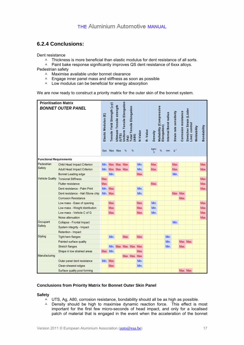
6.2.4 Conclusions: Dent resistance
Thickness is more beneficial than elastic modulus for dent resistance of all sorts. Paint bake response significantly improves QS dent resistance of 6xxx alloys.
Pedestrian safety Maximise available under bonnet clearance Engage inner panel mass and stiffness as soon as possible Low modulus can be beneficial for energy absorption
We are now ready to construct a priority matrix for the outer skin of the bonnet system.
Gpa Mpa Mpa % %kgm-
3% mm S-1
Child Head Impact Criterion Min. Max. Max. Max. Min. Max. Max. Max.
Adult Head Impact Criterion Min. Max. Max. Max. Min. Max. Max. Max.
Bonnet Leading edge Min. Max. Min.
Torsional Stiffness Max. Max.
Flutter resistance Max. Max. Max.
Dent resistance - Palm Print Min. Max. Min. Max.
Dent resistance - Hail /Stone chip Min. Max. Min. Max. Max.
Corrosion Resistance Max.
Low mass - Ease of opening Max. Max. Min. Max.
Low mass - Weight distribution Max. Max. Min. Max.
Low mass - Vehicle C of G Max. Max. Min. Max.
Noise attenuation Max.
Collapse - Frontal Impact Min.
System integrity - Impact
Retention - Impact
Tight hem flanges Min. Max. Max. Min.
Painted surface quality Min. Max. Max.
Stretch flanges Min. Max. Max. Max. Max. Min. Max.
Shape in low strained areas Max. Min. Max.
Max. Max. Max.
Outer panel dent resistance Min. Max. Min.
Clean sheared edges Max. Min.
Surface quality post forming Max. Max.
Vehicle Quality
Styling
Manufacturing
Occupant Safety
Ma
liab
ility
(C
om
pre
ss
ive
E
lon
ga
tio
n)
Inte
rna
l Be
nd
ra
diu
s
Functional Requirements
Pedestrian Safety
Prioritisation Matrix
BONNET OUTER PANELE
las
tic
Mo
du
lus
(E
)
Te
ns
ile Y
ield
Str
en
gth
(
y)
Ult
ima
te T
en
sile
str
en
gth
(U
TS
)U
nif
orm
Te
ns
ile E
lon
ga
tio
n
(Ag
)T
ota
l Te
ns
ile E
lon
ga
tio
n
(A8
0)
N-V
alu
e
R-
Va
lue
De
ns
ity
Str
etc
he
r S
tra
in (
Lü
de
r L
ine
) c
on
tro
l
We
lda
bili
ty
Str
ain
ra
te s
en
sit
ivit
y
Bo
nd
ab
ility
Co
rro
sio
n r
es
ista
nc
e
Conclusions from Priority Matrix for Bonnet Outer Skin Panel Safety
UTS, Ag, A80, corrosion resistance, bondability should all be as high as possible. Density should be high to maximise dynamic reaction force. This effect is most
important for the first few micro-seconds of head impact, and only for a localised patch of material that is engaged in the event when the acceleration of the bonnet

Version 2011 © European Aluminium Association ([email protected]) 18
skin is at its peak. This can be achieved more efficiently through engagement of the inner panel mass. Other effects dominate the energy absorption afterwards, hence low density is usually judged more beneficial for weight reduction.
Low, as-delivered, yield strength is usually accompanied by a high n- value (work hardening exponent); both are beneficial for good final panel geometry.
Yield strength is increased by forming strain and age hardening of 6xxx alloys during the paint bake cycle. High post forming yield strength is beneficial for the most severe cases of head impact. N-value and BH parameters should be maximised for the outer skin.
Quality
6xxx alloys are recommended for ‘A’ class painted surfaces in order to avoid the formation of stretcher strain (Lüder line) marks.
E and Yield strength requirements for global vehicle stiffness
◦ Global vehicle torsional and bending stiffness is decoupled from the bonnet system.
Bonnet stiffness is obtained through section properties and material thickness.
◦ Vibration stiffness is obtained from careful design of bonnet inner panel and anti-flutter mastic connecting it to the outer surface. Mastic properties and bead size are chosen so as to avoid print through or witness marks on the visible painted surface. The resulting stiffness is designed to be high enough to avoid visible flutter resulting from aerodynamic effects.
Considering the priority matrix for the inner panel of the bonnet system.

Version 2011 © European Aluminium Association ([email protected]) 19
Gpa Mpa Mpa % %kgm-
3% mm S-1
Child Head Impact Criterion Max. Max. Max. Min. Max. Max. Max.
Adult Head Impact Criterion Max. Max. Max. Min. Max. Max. Max.
Bonnet Leading edge Min. Max. Max. Max. Min.
Torsional Stiffness Max. Max.
Flutter resistance Max. Max.
Dent resistance - Palm Print Min. Max. Min. Max.
Dent resistance - Hail /Stone chip Min. Max. Min. Max.
Corrosion Resistance Max.
Low mass - Ease of opening Max. Max. Max. Max. Min. Max.
Low mass - Weight distribution Max. Max. Max. Max. Min. Max.
Low mass - Vehicle C of G Max. Max. Max. Max. Min. Max.
Noise attenuation Max.
Collapse - Frontal Impact Max. Max. Min.
System integrity - Impact Max. Max. Max. Max. Max.
Retention - Impact Max. Max. Max. Max. Max.
Tight hem flanges Min. Max. Max. Min.
Painted surface quality Max.
Stretch flanges Min. Max. Max. Max. Max. Min.
Shape in low strained areas Max. Min. Max. Max. Max.
Paint drain features Max. Max. Max. Max.
Outer panel dent resistance Max. Min.
Clean sheared edges Max. Max. Min.
Surface quality post forming Max. Max.
Galling resistance - inner panel Max. Min. Min.
Manufacturing
Occupant Safety
Functional Requirements
Pedestrian Safety
Vehicle Quality
Styling
To
tal T
en
sile
E
lon
ga
tio
n (
A8
0)
N-V
alu
e
Fri
cti
on
co
eff
icie
nt
We
lda
bili
ty
Bo
nd
ab
ility
R-
Va
lue
De
ns
ity
Ma
liab
ility
(C
om
pre
ss
ive
Inte
rna
l Be
nd
ra
diu
s
Str
ain
ra
te s
en
sit
ivit
y
Co
rro
sio
n r
es
ista
nc
e
Ult
ima
te T
en
sile
s
tre
ng
th (
UT
S)
Un
ifo
rm T
en
sile
E
lon
ga
tio
n (
Ag
)
Prioritisation Matrix
BONNET INNER PANEL
Ela
sti
c M
od
ulu
s (
E)
Te
ns
ile Y
ield
Str
en
gth
(
y)
Conclusions from Priority Matrix for Bonnet Inner Panel
Safety UTS, Ag, A80, corrosion resistance, bondability should all be as high as possible. Low as delivered yield strength is usually accompanied by a high n- value (work
hardening exponent); both are beneficial for good stretch capability. Yield strength is increased by forming strain and age hardening of 6xxx alloys during
the paint bake cycle. High post forming yield strength is beneficial for the most severe cases of head impact. N-value and BH parameters should be maximised if possible for the inner panel, however, deeper sections may be possible for non-heat treatable 5xxx alloys.
R-value should be high for the draw operation, although these panels tend to be quite shallow stampings.
Quality E and Yield strength requirements for global vehicle stiffness.
◦ Global vehicle torsional and bending stiffness is decoupled from the bonnet system.
Bonnet stiffness is obtained through section properties and material thickness.
◦ Vibration stiffness is obtained from careful design of bonnet inner panel and anti-flutter mastic connecting it to the outer surface. Mastic properties and bead size are chosen so as to avoid print through or witness marks on the visible painted surface. The resulting stiffness is designed to be high enough to avoid visible flutter resulting from aerodynamic effects.
Version 2011 © European Aluminium Association ([email protected]) 20
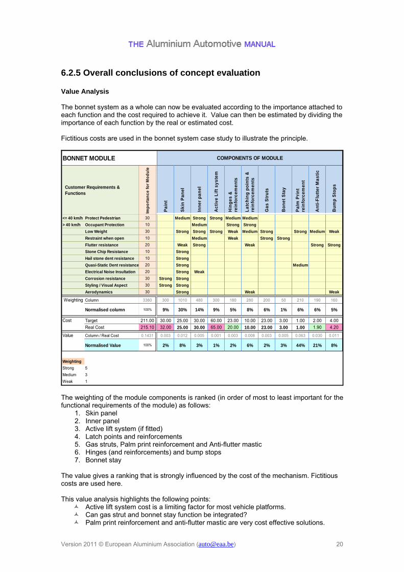
6.2.5 Overall conclusions of concept evaluation Value Analysis The bonnet system as a whole can now be evaluated according to the importance attached to each function and the cost required to achieve it. Value can then be estimated by dividing the importance of each function by the real or estimated cost. Fictitious costs are used in the bonnet system case study to illustrate the principle.
<= 40 km/h Protect Pedestrian 30 Medium Strong Strong Medium Medium
> 40 km/h Occupant Protection 10 Medium Strong Strong
Low Weight 30 Strong Strong Strong Weak Medium Strong Strong Medium Weak
Restraint when open 10 Medium Weak Strong Strong
Flutter resistance 20 Weak Strong Weak Strong Strong
Stone Chip Resistance 10 Strong
Hail stone dent resistance 10 Strong
Quasi-Static Dent resistance 20 Strong Medium
Electrical Noise Insultation 20 Strong Weak
Corrosion resistance 30 Strong Strong
Styling / Visual Aspect 30 Strong Strong
Aerodynamics 30 Strong Weak Weak
Column 3360 300 1010 480 300 180 280 200 50 210 190 160
Normalised column 100% 9% 30% 14% 9% 5% 8% 6% 1% 6% 6% 5%
Target 211.00 30.00 25.00 30.00 60.00 23.00 10.00 23.00 3.00 1.00 2.00 4.00
Real Cost 215.10 32.00 25.00 30.00 65.00 20.00 10.00 23.00 3.00 1.00 1.90 4.20
Column / Real Cost 0.1431 0.003 0.012 0.005 0.001 0.003 0.008 0.003 0.005 0.063 0.030 0.011
Normalised Value 100% 2% 8% 3% 1% 2% 6% 2% 3% 44% 21% 8%
Weighting
Strong 5
Medium 3
Weak 1
BONNET MODULE
Weighting
Value
Pa
lm P
rin
t re
info
rce
me
nt
An
ti-F
lutt
er
Ma
sti
c
COMPONENTS OF MODULE
Hin
ge
s &
re
info
rce
me
nts
La
tch
ing
po
ints
&
rein
forc
em
en
ts
Ga
s S
tru
ts
Inn
er
pa
ne
l
Ac
tiv
e L
ift
sy
ste
m
Imp
ort
an
ce
fo
r M
od
ule
Customer Requirements & Functions
Cost
Pa
int
Sk
in P
an
el
Bo
ne
t S
tay
Bu
mp
Sto
ps
The weighting of the module components is ranked (in order of most to least important for the functional requirements of the module) as follows:
1. Skin panel 2. Inner panel 3. Active lift system (if fitted) 4. Latch points and reinforcements 5. Gas struts, Palm print reinforcement and Anti-flutter mastic 6. Hinges (and reinforcements) and bump stops 7. Bonnet stay
The value gives a ranking that is strongly influenced by the cost of the mechanism. Fictitious costs are used here. This value analysis highlights the following points:
Active lift system cost is a limiting factor for most vehicle platforms. Can gas strut and bonnet stay function be integrated? Palm print reinforcement and anti-flutter mastic are very cost effective solutions.
Version 2011 © European Aluminium Association ([email protected]) 21
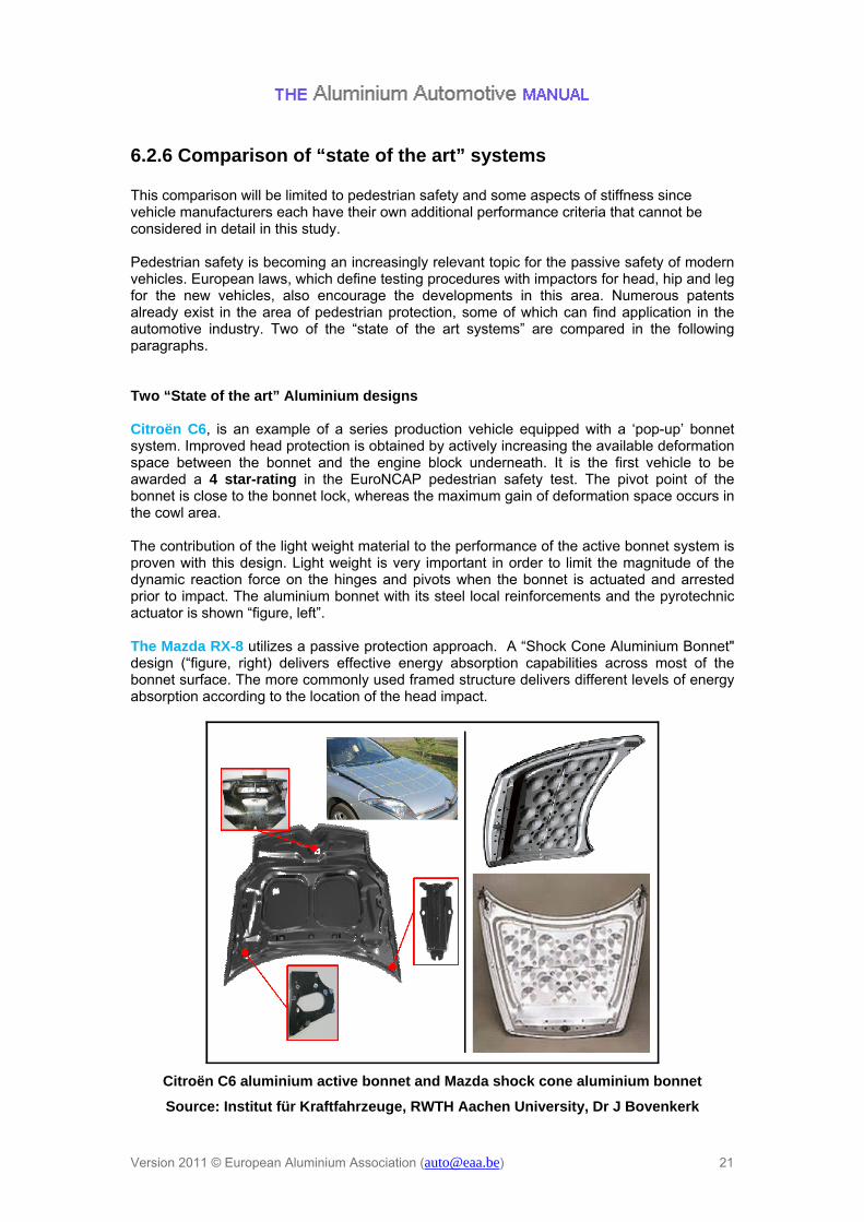
6.2.6 Comparison of “state of the art” systems This comparison will be limited to pedestrian safety and some aspects of stiffness since vehicle manufacturers each have their own additional performance criteria that cannot be considered in detail in this study. Pedestrian safety is becoming an increasingly relevant topic for the passive safety of modern vehicles. European laws, which define testing procedures with impactors for head, hip and leg for the new vehicles, also encourage the developments in this area. Numerous patents already exist in the area of pedestrian protection, some of which can find application in the automotive industry. Two of the “state of the art systems” are compared in the following paragraphs. Two “State of the art” Aluminium designs Citroën C6, is an example of a series production vehicle equipped with a ‘pop-up’ bonnet system. Improved head protection is obtained by actively increasing the available deformation space between the bonnet and the engine block underneath. It is the first vehicle to be awarded a 4 star-rating in the EuroNCAP pedestrian safety test. The pivot point of the bonnet is close to the bonnet lock, whereas the maximum gain of deformation space occurs in the cowl area. The contribution of the light weight material to the performance of the active bonnet system is proven with this design. Light weight is very important in order to limit the magnitude of the dynamic reaction force on the hinges and pivots when the bonnet is actuated and arrested prior to impact. The aluminium bonnet with its steel local reinforcements and the pyrotechnic actuator is shown “figure, left”. The Mazda RX-8 utilizes a passive protection approach. A “Shock Cone Aluminium Bonnet" design (“figure, right) delivers effective energy absorption capabilities across most of the bonnet surface. The more commonly used framed structure delivers different levels of energy absorption according to the location of the head impact.
Citroën C6 aluminium active bonnet and Mazda shock cone aluminium bonnet
Source: Institut für Kraftfahrzeuge, RWTH Aachen University, Dr J Bovenkerk

Version 2011 © European Aluminium Association ([email protected]) 22
Comparing Aluminium with Steel bonnets Test and analysis results show that the stiffness and the pedestrian protection potential of a bonnet are linked. A study comparing an aluminium and a steel bonnet [Roberto Puppini, Roger Hardy, et al., “Concepts of protection to address child and adult head impacts”, APROSYS report AP-SP34-004R, Deliverable D3.4.2C] is referred to here in order to assess the effect of different materials on the stiffness and pedestrian safety. This study compares the Citroën C6 aluminium bonnet with the Fiat Stilo steel bonnet (“figure, upper”). Different load cases have been studied for obtaining the lateral, transversal and torsional stiffness values. The stiffness test results obtained by applying the defined loads to both the outer and inner sheets of the two bonnets are shown in “figure, lower”. By inspection it is clear that a higher stiffness is always obtained from the steel bonnet. The steel bonnet, in contrast to the aluminium bonnet, has not been optimised for pedestrian protection requirements. The outstanding performance of the Citroën C6 in pedestrian protection results from a combination of the aluminium material properties, optimised bonnet geometry and other measures such as the active lift mechanism increasing the available deformation space. Without structural optimisation for aluminium, the aluminium bonnet would deliver inferior results in some areas, owing to a secondary head impact with the engine block.

Version 2011 © European Aluminium Association ([email protected]) 23
C6
Material Aluminium
Outer sheet
1.20 mm
Inner sheet
1.00 mm
Stilo
Material Steel
Outer sheet
0.70 mm
Inner sheet
0.65 mm
0
100
200
300
400
500
600
0 1 2 3 4 5 6 7 8 9 10 11 12 13 14
For
ce [N
]
Lateral
Deflection [mm]
0
100
200
300
400
500
600
0 1 2 3 4 5 6 7 8 9 10 11 12 13 14
Transversal
Deflection [mm]
For
ce [N
]
0
20
40
60
80
100
120
0 2 4 6 8 10 12 14 16 18 20 22 24 26 28 30
Deflection [mm]
Torsional
For
ce [N
]
Stiffness tests on Citroën C6 and Fiat Stilo bonnet
Source: Roberto Puppini, Roger Hardy, et al., “Concepts of protection to address child and adult head impacts”, APROSYS report AP-SP34-004R, Deliverable D3.4.2C

Version 2011 © European Aluminium Association ([email protected]) 24
Performance evaluation A reference study was carried out on two identical bonnets, one made of aluminium, the other of steel, in order to evaluate the pedestrian protection performance implications related to the materials used. The tests were conducted on a vehicle that was available at the time of the study with both steel and aluminium bonnet versions, which enables a pure material comparison. The testing procedure specified by EEVC-WG 17 was used with both child and adult head impactors to assess the energy absorbing behaviour of the bonnets with the aim of determining which material is most favourable. Unfortunately, the bonnet design was not optimised for pedestrian impact. While the steel bonnet consists of 0.7 mm thick IF-Rephos steel (outer) and 0.6 mm deep-drawing steel (inner), the aluminium bonnet consists of 1.0 mm thick 6000 series aluminium for both the outer and inner panels. Two test locations are compared for the steel and aluminium bonnet.
Steel and aluminium acceleration curves for two specially chosen impact locations on the bonnet
Source: Dominik Schwarz, Harald Bachem, Edward Opbroek; “Comparison of steel and aluminium hood with same design in view of pedestrian head impact”; 2004-01-1605,
SAE International
A secondary impact on the underlying structure takes place during the impact of adult head location 1 (AH-L-1). This leads to a higher first acceleration peak for the steel version and a higher secondary acceleration peak for aluminium version. The aluminium version absorbs less energy during the first impact peak than the steel version. As a result, the relative velocity, acceleration and HIC in the secondary impact are higher for the aluminium version. On the other hand, the impact of child head location M2 (CH-M-2) reveals no significant secondary impact on the underlying structure. As for AH-L-1, there is a higher initial acceleration peak for the steel version and more deformation for the aluminium version. However, the calculated HIC value for the aluminium version is lower in this case because of the absence of a secondary acceleration peak. This study demonstrates the influence of a secondary impact with the underlying structure on the HIC value. When designing a bonnet with aluminium:
1. Ensure that sufficient deformation space is available in order to avoid significant secondary impacts.
a. “Pop up” bonnet b. Lower under bonnet “hard” points
2. Maximise bonnet static stiffness a. Check for loss of stiffness b. Avoid discontinuities in section stiffness.
3. Maximise bonnet dynamic stiffness a. Maximise outer skin yield strength

Version 2011 © European Aluminium Association ([email protected]) 25
b. Involve inner structure mass as early as possible in most critical clearance locations
6.3 Conclusions from bonnet and boot lid case study A constructive solution can be found for both steel and aluminium. The general assumption that either aluminium or steel bonnets is always better for pedestrian head impact is proven to be invalid. The focus should be on optimising the structure according to the material properties and the deformation space available.