Embed Size (px)
Citation preview
Design Basic- system
Emergency Exit Control

The DORMA Design Basic System as electrical locking system in emergency exit doors comes with all the elegance of our System 55 modular design. The newly developed independent emergency exit system for concealed flush mounting provides reliable emergency exit control for individual doors wherever a network solution is either not necessary or not possible.The DORMA Design Basic System for the prevention of the door abuse in emergency
exit and escape routes (as prescribed e.g. by prEN 13637 consists of an emergency pushbutton, a keyswitch, a control unit, a power supply unit (or optional power supply by others) and an door locking device. Also available as an optional extra is an emergency escape lock with automatic locking action compliant with e.g. German insurance regulations. The emergency exit system can also be operated via an access control system.
DORMA Emergency Exit Control
Design Basic System
2
2Extremely attractive solution for providing reliable emergency exit control, even in buildings with only a few emergency exit doors.
2Easy to fit with installation in deepset standard flushmounting device boxes.
2System 55 suitable for combination with all DORMA cover trims (“frames”) and similar components of many other leading international suppliers such as GIRA Berker, Merten,
Jung.
2Internal wiring via plugin ribbon cable.
2Monitoring module LEDs instantly indicate door status.
2Locking/unlocking via integrated keyswitch and momentary contact control mechanism.
2Illuminated emergency pushbutton under transparent lens with antitamper contact for effective protection against misuse.
Benefits
DORMA emergency exit control systems comply with the German EltVTR code of practice [“Requirements for electrical locking systems on doors in emergency escape routes”] and provisional European standard prEN 13637.
Approval certification
Additional information concerning many of our products is available from a range of electronic media (Internet, CDROM). The abbreviated codes beside the computer icon b are the search terms.
b
Design Basic System, GB Design Basic System, GB
Independent emergency exit control for individual doors DORMA Design Basic System
Securely locked during everyday use, yet quick and easy to open in the event of an emergency. These are the most important requirements that have to be met by doors in emergency exit and escape routes.Electronic emergency exit control systems are best suited to reconciling the associated criteria.
Simply safe and secure
�Design Basic System, GB
Data and features
TL-ST S 55
TL-N S 55 UP
TL-S 55 UP
24
12
20
85
0-
12
00
mm
24 V DC 0.5 Aby others
or230 V AC +/-10 %
RZ 01
TV
SVP 5000
TS
RM
AS or BL
TG/TEGMA/BMAPFS
DesignBasic System
TL-ST S 55TL-S 55 UP
TL-N S 55
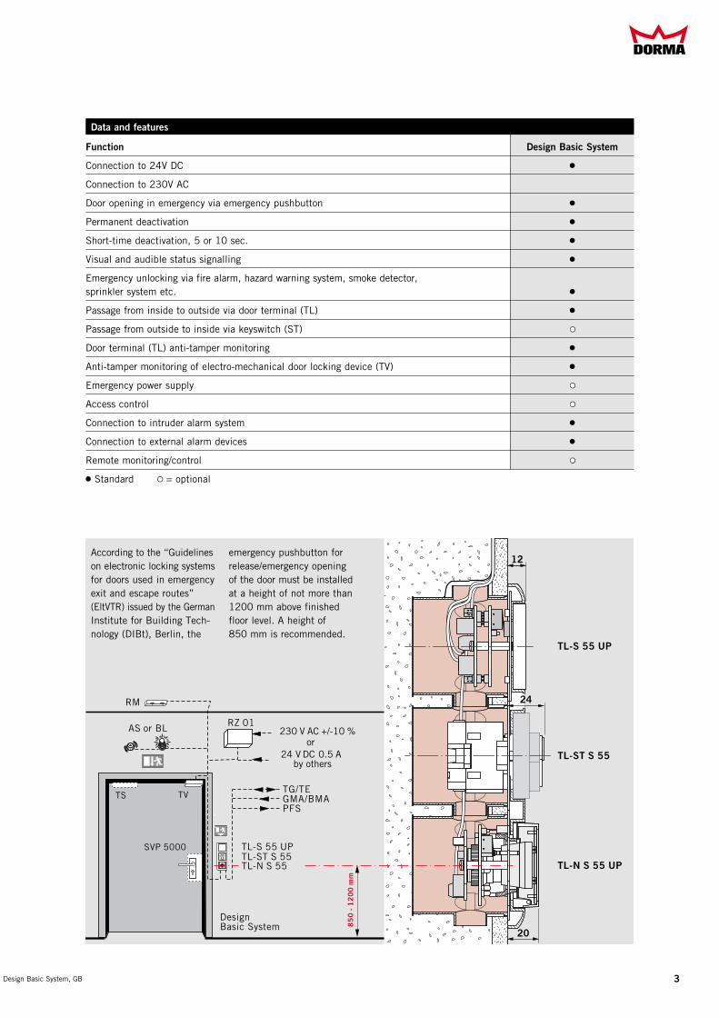
According to the “Guidelines on electronic locking systems for doors used in emergency exit and escape routes” (EltVTR) issued by the German Institute for Building Technology (DIBt), Berlin, the
emergency pushbutton for release/emergency opening of the door must be installed at a height of not more than 1200 mm above finished floor level. A height of 850 mm is recommended.
Function Design Basic System
Connection to 24V DC 2
Connection to 230V AC
Door opening in emergency via emergency pushbutton 2
Permanent deactivation 2
Shorttime deactivation, 5 or 10 sec. 2
Visual and audible status signalling 2
Emergency unlocking via fire alarm, hazard warning system, smoke detector, sprinkler system etc. 2
Passage from inside to outside via door terminal (TL) 2
Passage from outside to inside via keyswitch (ST) 2§
Door terminal (TL) antitamper monitoring 2
Antitamper monitoring of electromechanical door locking device (TV) 2
Emergency power supply 2§
Access control 2§
Connection to intruder alarm system 2
Connection to external alarm devices 2
Remote monitoring/control 2§
2 Standard § = optional
X3
X4
X7
X2B S
S1
S2
PFSTET1/T2
AV
ON 151716 18 7 6 5 4 3
X9X8
X6
Sabo GMA
4142 3 202 3 3 4 5 1
X1
S1
S2S B
B A
X7
X15X16
X14S3
X13 X4
3 16 1 4241 6 5 4
10a2 2 10
42
41X1
Sabo
3
17
20
15
16
3
4
3
5
4
6
5
7
1
8
1
2
3
GMA
PFS
TV
TE
X2
X6
X7
GND
GNDGND+24 V DC+24 V DC
+24 V DC+24 V DC+24 V DC
+24 V DCCNCNO
+24 V DC
+24 V DC
GND
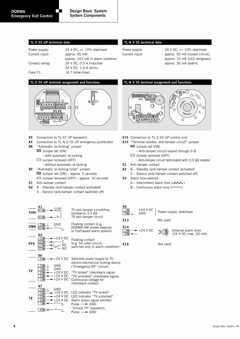
TV anti-tamper circuit/line resistance 3.3 kÖ TV anti-tamper circuit
Floating contact (e.g. DORMA RM smoke detector or fire/hazard alarm system)
Switched power supply to TV electro-mechanical locking device (“Emergency Off” circuit)
“TV locked” checkback signal, “TV unlocked” checkback signal, Continuous voltage for checkback contact
Floating contact (e.g. for video circuit, switches only in alarm condition)
3,3 kÖ
16
13
X14
X16
X13
X4
GND+24 V DC
+24 V DC
Power supply, stabilised
Not used
External alarm siren(24 V DC; max. 50 mA)
Not used
LED indicator “TV locked”, LED indicator “TV unlocked”, Alarm (piezo signal emitter) Pulse GND “Unlock TV” keyswitch, Pulse GND
4
DORMA TS 9�
Gleitschienen- Türschließersystem
DORMA Emergency Exit Control
Design Basic System System Components
Design Basic System, GB Design Basic System, GB
TL-S 55 UP terminal assignment and functions TL-N S 55 terminal assignment and functions
Power supply: 24 V DC, +/ 10% stabilisedCurrent input: approx. 50 mA (closed circuit), approx. 15 mA (LED red/green), approx. 30 mA (alarm)
Power supply: 24 V DC, +/ 10% stabilisedCurrent input: approx. 95 mA/ approx. 143 mA in alarm conditionContact rating: 24 V DC, 0.5 A inductive 24 V DC, 1.0 A ohmicFuse F1: 1A T (slowblow)
TL-N S 55 technical dataTL-S 55 UP technical data
X� Connection to TLST UP keyswitch X4 Connection to TLN S 55 UP emergency pushbutton X8 “Automatic relocking” jumper Jumper set (ON) – with automatic relocking Jumper removed (OFF) – without automatic relocking X9 “Automatic relocking timer” jumper Jumper set (ON) – approx. 5 seconds Jumper removed (OFF) – approx. 10 seconds S1 Antitamper contact S2 B – Standby (antitamper contact activated) S – Service (antitamper contact switched off)
X15 Connection to TLS 55 UP control unit X15 “Terminal resistor, antitamper circuit” jumper Jumper set (ON) – Antitamper circuit looped through 0 Ö Jumper removed (OFF) – Antitamper circuit terminated with 3.3 kÖ resistor S1 Antitamper contact S2 B – Standby (antitamper contact activated) S – Service (antitamper contact switched off) S� Alarm tone selector A – Intermittent alarm tone ( ) B – Continuous alarm tone ( )
Scheibe eindrücken
push for emergency
055734-01-1-40 DORMA GmbH + Co. KG
X1X6
X3
X4
X9X8
X7X2
B S
S1
S2
10,5
30
Scheibe eindrücken
push for emergency
055734-01-1-40 DORMA GmbH + Co. KG
X1X6
X3
X4
X9X8
X7X2
B S
S1
S2
10,5
30
Scheibe eindrücken
push for emergency
055734-01-1-40 DORMA GmbH + Co. KG
X1X6
X3
X4
X9X8
X7X2
B S
S1
S2
10,5
30
Scheibe eindrücken
push for emergency
055734-01-1-40 DORMA GmbH + Co. KG
X1X6
X3
X4
X9X8
X7X2
B S
S1
S2
10,5
30
5Design Basic System, GB
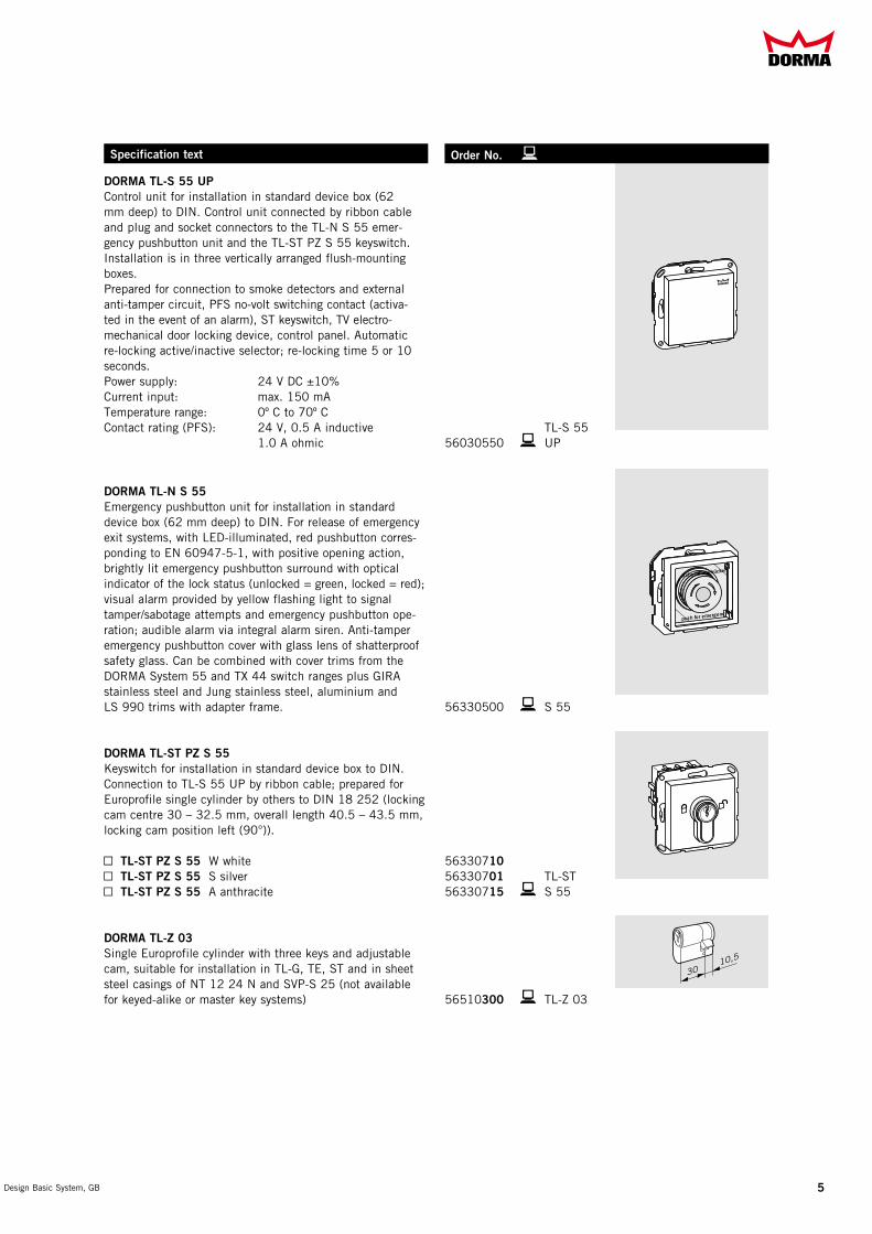
DORMA TL-S 55 UP Control unit for installation in standard device box (62 mm deep) to DIN. Control unit connected by ribbon cable and plug and socket connectors to the TLN S 55 emergency pushbutton unit and the TLST PZ S 55 keyswitch. Installation is in three vertically arranged flushmounting boxes.Prepared for connection to smoke detectors and external antitamper circuit, PFS novolt switching contact (activated in the event of an alarm), ST keyswitch, TV electromechanical door locking device, control panel. Automatic relocking active/inactive selector; relocking time 5 or 10 seconds.Power supply: 24 V DC ±10%Current input: max. 150 mATemperature range: 0º C to 70º CContact rating (PFS): 24 V, 0.5 A inductive TLS 55 1.0 A ohmic 56030550 bUP
DORMA TL-N S 55 Emergency pushbutton unit for installation in standard device box (62 mm deep) to DIN. For release of emergency exit systems, with LEDilluminated, red pushbutton corresponding to EN 6094751, with positive opening action, brightly lit emergency pushbutton surround with optical indicator of the lock status (unlocked = green, locked = red); visual alarm provided by yellow flashing light to signal tamper/sabotage attempts and emergency pushbutton operation; audible alarm via integral alarm siren. Antitamper emergency pushbutton cover with glass lens of shatterproof safety glass. Can be combined with cover trims from the DORMA System 55 and TX 44 switch ranges plus GIRA stainless steel and Jung stainless steel, aluminium andLS 990 trims with adapter frame. 56330500 bS 55
DORMA TL-ST PZ S 55 Keyswitch for installation in standard device box to DIN. Connection to TLS 55 UP by ribbon cable; prepared for Europrofile single cylinder by others to DIN 18 252 (locking cam centre 30 – 32.5 mm, overall length 40.5 – 43.5 mm, locking cam position left (90°)).
Y TL-ST PZ S 55 W white 56330710Y TL-ST PZ S 55 S silver 56330701 TLSTY TL-ST PZ S 55 A anthracite 56330715 bS 55
DORMA TL-Z 0� Single Europrofile cylinder with three keys and adjustable cam, suitable for installation in TLG, TE, ST and in sheet steel casings of NT 12 24 N and SVPS 25 (not available for keyedalike or master key systems) 56510�00 bTLZ 03
Specification text Order No. b

6
DORMA Emergency Exit Control
Design Basic System System Components
Design Basic System, GB Design Basic System, GB
Specification text Order No. b
DORMA TV 1xx Electromechanical door locking device (failsafe principle) with antitamper and door monitoring contacts, integrated positiveaction monitoring for active/inactive status. Housed in painted anticorrosion and antitamper metal enclosure. Supply includes mountings, shim set and full set of screw fixings. Max. holding force per “Requirements for electrical locking systems on doors in emergency escape routes” (German EltVTR code of practice) with loadindependent jamfree unlocking.
Power supply: 24 V DC ± 10%Current input max.: 250 mAContact rating: 24 V DC, 0.5 A inductive 24 V DC, 1.0 A ohmicRecommended cabling: IY (ST) Y4 x 2 x 0.6 mmDimensions (W x H x D): approx. 190 x 58 x 87 mm
TV 101 silver 56022101 bTV 1xx
DORMA TV-Z01 Shim set to compensate for installation tolerances when mounting the DORMA TV 1xx electromechanical door locking device. 2 shims 1 mm thick, 1 shim 3 mm thick.
DORMA TV 2xx Electromechanical door locking device (failsafe principle) with antitamper and door monitoring contacts, integrated positiveaction monitoring for active/inactive status. Housed in painted anticorrosion and antitamper metal enclosure.Supply includes amatureplate (also for fire doors) and full set of screw fixings. Max. holding force per “Requirements for electrical locking systems on doors in emergency escape routes” (German EltVTR code of practice) with loadindependent jamfree unlocking.
Power supply: 24 V DC ± 10%Current input max.: 200 mAContact rating: 24 V DC, 0.5 A inductive 24 V DC, 1.0 A ohmicRecommended cabling: IY (ST) Y4 x 2 x 0.6 mmDimensions (W x H x D): approx. 190 x 58 x 87 mm
TV 201 silver 56022201 bTV 2xx
DORMA TVZ-1xx Mounting unit for installation of DORMA TV 1xx / TV 2xx electromechanical door locking device on flushclosing doors. Galvanised steel angle bracket with painted cover; screw fixings tamperprotected.
Dimensions (W x H x D): approx. 190 x 58 x 87 mm
TVZ 101 silver 56522201 bTVZ1xx
For further device details and colours, see TV technical brochure

TV
508
7Design Basic System, GB
Specification text Order No. b
DORMA TV 5xx Electro-mechanical door locking device with integrated checkback signal contacts for monitoring active/inactive status. Supplied with rebated or flanged strike plate and full set of screw fixings. Max. holding force per “Requirements for electrical locking systems on doors in emergency escape routes” (German EltVTR code of practice) with load-independent jam-free unlocking.
Power supply: 24 V DC ± 5%Current input max.: 160 mAContact rating: 24 V DC, 0.5 A inductive 24 V DC, 1.0 A ohmicRecommended cabling: I-Y (ST) Y4 x 2 x 0.6 mmDimensions (W x H x D)without strike plate: approx. 23 x 134 x 39 mm
With rebated strike plate 30 x 48 x 220 x 3 mmfor over-rebated doorsY TV 501 ISO 6 (LH) 15150124Y TV 502 ISO 5 (RH) 15150224 bTV 5xx
With flanged strike plate 25 x 300 x 3 mmfor flush-closing doorsY TV 505 ISO 6 (LH) 15150524Y TV 506 ISO 5 (RH) 15150624 bTV 5xx
With flanged strike plate 25 x 300 x 3 mm with latch guide for flush-closing doors Y TV 507 ISO 6 (LH) 15150724Y TV 508 ISO 5 (RH) 15150824 bTV 5xx
DORMA TV-Z 510 Mortise latch matched to TV 50xfor installation in the door leaf.Y Forend dimensions: 24 x 110 x 3 15198124Y Forend dimensions: 24 x 110 x 3, edges rounded 15198224Y Forend dimensions: 28 x 110 x 3 15198128Y Forend dimensions: 20 x 110 x 3 15198120 bTV-Z 500
PSU-24 Switched power supply unit to EN 60950 for installation in standard device box l 65 mm.Input voltage: 24V AC ± 10%, 50/60 HzOutput voltage: 24V DCMax. output current: 0.5 ADimensions: 51 x 51 x 24 mm (max. diagonal 55 mm) 56030101 bPSU-24
RZ-01 Power supply unit in IP 21 plastics enclosure with LED indicator showing operating status.Input voltage: 230V AC ± 10%, 50/60 HzOutput voltage: 24V DCMax. output current: 0.6 ADimensions (W x H x D): approx. 160 x 80 x 50 mm 56030100 bRZ-01
NT 24-1.5 power supply unit Power supply unit in IP 21 plastics enclosure with LED indicator showing operating status.Input voltage: 230V AC ± 15%, 50/60 HzOutput voltage: 24V DCMax. output current: 1.5 ADimensions (W x H x D): approx. 200 x 120 x 75 mm 56332100 bNT 24-1.5
8
DORMA Emergency Exit Control
Design Basic System Cover Trims
Design Basic System, GB Design Basic System, GB
Specification text Order No. b
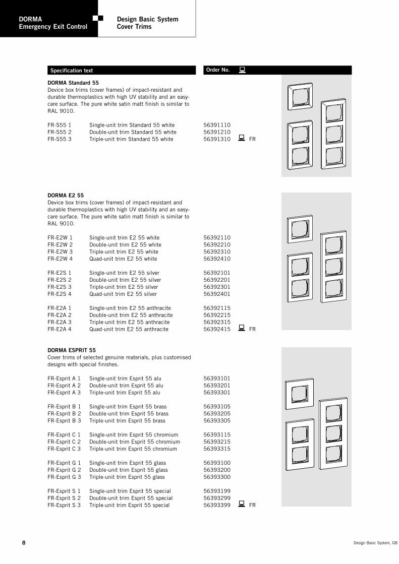
DORMA Standard 55 Device box trims (cover frames) of impact-resistant and durable thermoplastics with high UV stability and an easy-care surface. The pure white satin matt finish is similar to RAL 9010.
FR-S55 1 Single-unit trim Standard 55 white 56391110FR-S55 2 Double-unit trim Standard 55 white 56391210FR-S55 3 Triple-unit trim Standard 55 white 56391310 bFR
DORMA E2 55 Device box trims (cover frames) of impact-resistant and durable thermoplastics with high UV stability and an easy-care surface. The pure white satin matt finish is similar to RAL 9010.
FR-E2W 1 Single-unit trim E2 55 white 56392110FR-E2W 2 Double-unit trim E2 55 white 56392210FR-E2W 3 Triple-unit trim E2 55 white 56392310FR-E2W 4 Quad-unit trim E2 55 white 56392410
FR-E2S 1 Single-unit trim E2 55 silver 56392101FR-E2S 2 Double-unit trim E2 55 silver 56392201FR-E2S 3 Triple-unit trim E2 55 silver 56392301FR-E2S 4 Quad-unit trim E2 55 silver 56392401
FR-E2A 1 Single-unit trim E2 55 anthracite 56392115FR-E2A 2 Double-unit trim E2 55 anthracite 56392215FR-E2A 3 Triple-unit trim E2 55 anthracite 56392315FR-E2A 4 Quad-unit trim E2 55 anthracite 56392415 bFR
DORMA ESPRIT 55 Cover trims of selected genuine materials, plus customised designs with special finishes.
FR-Esprit A 1 Single-unit trim Esprit 55 alu 56393101FR-Esprit A 2 Double-unit trim Esprit 55 alu 56393201FR-Esprit A 3 Triple-unit trim Esprit 55 alu 56393301
FR-Esprit B 1 Single-unit trim Esprit 55 brass 56393105FR-Esprit B 2 Double-unit trim Esprit 55 brass 56393205FR-Esprit B 3 Triple-unit trim Esprit 55 brass 56393305
FR-Esprit C 1 Single-unit trim Esprit 55 chromium 56393115FR-Esprit C 2 Double-unit trim Esprit 55 chromium 56393215FR-Esprit C 3 Triple-unit trim Esprit 55 chromium 56393315
FR-Esprit G 1 Single-unit trim Esprit 55 glass 56393100FR-Esprit G 2 Double-unit trim Esprit 55 glass 56393200FR-Esprit G 3 Triple-unit trim Esprit 55 glass 56393300
FR-Esprit S 1 Single-unit trim Esprit 55 special 56393199FR-Esprit S 2 Double-unit trim Esprit 55 special 56393299FR-Esprit S 3 Triple-unit trim Esprit 55 special 56393399 bFR

�Design Basic System, GB
Specification text Order No. b
DORMA TX 44 Reinforced cover trims of robust material for theft-proof installation. Either the transparent hinged cover or the seal set will be required in order to achieve class of protection IP 44 (splash-proof enclosure) for use in wet rooms or outdoor areas.
FR-TX44 W 1 Single-unit trim, IP 44 white 56394110FR-TX44 W 2 Double-unit trim, IP 44 white 56394210FR-TX44 W 3 Triple-unit trim, IP 44 white 56394310FR-TX44 W KDT Transparent hinged cover, white 56399010
FR-TX44 S 1 Single-unit trim, IP 44 silver 56394101FR-TX44 S 2 Double-unit trim, IP 44 silver 56394201FR-TX44 S 3 Triple-unit trim, IP 44 silver 56394301FR-TX44 S KDT Transparent hinged cover, silver 56399001
FR-TX44 A 1 Single-unit trim, IP 44 anthracite 56394115FR-TX44 A 2 Double-unit trim, IP 44 anthracite 56394215FR-TX44 A 3 Triple-unit trim, IP 44 anthracite 56394315FR-TX44 A KDT Transparent hinged cover, anthracite 56399015 bFR
Set of seals for System 55 components 56399000
DORMA Design Column 1.4 m Including TX 44 quad-unit trim for the integration of System 55 components. The empty boxes can also be used to incorporate any function from the water-protected TX 44 range of switches and devices. Either the transparent hinged cover or the seal set will be required in order to achieve class of protection IP 44 (splash-proof enclosure) for use in wet rooms or outdoor areas.
Design Column 1.4 m incl. TX 44 quad-unit trim, pure white 56395010Design Column 1.4 m incl. TX 44 quad-unit trim, silver 56395001Design Column 1.4 m incl. TX 44 quad-unit trim, anthracite 56395015

10
DORMA Emergency Exit Control
Design Basic System Circuit Diagram
DORMA Emergency Exit Control
Safety Information
Design Basic System, GB Design Basic System, GB
PFSTET1/T2A
VO
N151716 18 7 6 5 4 3
X4
X9X8
X7X2
PFSTET1/T2A
VO
N151716 18 7 6 5 4 3
X4
X9X8
X7X2
X1X6
Sabo GMAX3
4142 3 202 3 3 4 5 1
S1
X5
X2
41
42
1
2
2
3
4
5
1
18
19X124
VD
C/m
ax.2
50
mA
I - Y (ST) Y 4 x 2 x 0.8Install cable in protective trunking
TL-S 55 UP
TV 1xx
X1X6
X3
X4
X9X8
X7 X2
B A
X15X16
X7
X14S3
X13 X4
TL-N S55 UP
2P1
TL-ST S55
24 V DC+15% / -10%
TL-S 55 UP
GMA
X1
PFSTET1/T2
AV
ON
151716 18 7 6 5 4 3
X4
X9X8
X7X2
PFSTET1/T2
AV
ON
151716 18 7 6 5 4 3
X4
X9X8
X7X2
191819a
5 14 23
X6
SaboX3
4142 3 202 3 3 4 5 1
TL-S 55 UP
TV 50x
I - Y (ST) Y 4 x 2 x 0.8Install cable in protective trunking
X1
11
DORMA Emergency Exit Control
Safety Information
Design Basic System, GB
DORMA emergency exit control systems have been developed and manufactured in accordance with the state of the art and generally recognised safety regulations. The systems comply with German code of practice “Guide-lines on electric locking systems for doors used in emergen-cy exits and escape routes” (EltVTR, December 1997 edition) published in bulletin 5/98 of the German Institute for Building Technology (DIBt), Berlin. Their suitability has been verified by the MPA NRW (Material Testing Authority), Dortmund, and the VdS (Association of Property Insurers), Cologne.
The installer and owner/operator must ensure compliance with the following requirements as these devices must not be allowed to prevent the unhindered escape of persons in the event of an emergency.
UseEmergency exit control systems are electric locking systems for doors in emergency exits and escape routes. They are designed to prevent the improper use of emergency exits. When installing and using DORMA emergency exit control systems, it is essential that proper consideration is given to the technical data and local conditions.
Preliminary building enquiry / Planning application / Approval procedure Emergency exit systems are often covered by existing building regulations.
In addition, the requirements according to prEN 13637 should also be regarded as ancillary regulations that need to be incorporated within the building approval process for the project in hand.
Planning and installationsAn emergency exit control system consists at least of the following components: Door terminal/door management sys-tem (TMS) and an electro-mechanical locking device (TV).
The following may also be connected to the emergency exit control, depending on the system design: Keyswitch or access control system, monitoring and control unit, emer-gency escape/anti-panic lock with automatic locking action (either switch-monitored or of motor lock design), flashing lamp or external alarm siren, automatic swing door operator, power supply unit/power pack, fire and/or hazard detection and alarm system and smoke detectors/switches.
The electro-mechanical locking device may only be used on emergency exits in conjunction with DORMA-approved products.
The door terminal (for local anti-panic release/emergency opening of door) must be installed in the immediate vicinity of the door handle so that the centre of the emergency pushbutton is at a height of 850 to max. 1200 mm above finished floor level.
The emergency-open pushbutton must be indicated by means of an “Emergency exit” sticker. This sticker should be positioned so that the arrow points towards the emergency-open pushbutton.
In buildings with automatic fire extinguishing equipment, fire alarm and other hazard warning systems, anti-abuse emergency escape doors which are electrically locked must be automatically released for escape on response/activation of these systems.
If, during building occupancy, there is a constantly manned control centre with a direct view of the emergency escape doors, the release operation can, instead, be performed from this position.
The properties and characteristics of the fire and smoke check doors (fire resistance time, smoke retention/sealing function and automatic closing action) must not be impaired by the installation of the electro-mechanical locking device.
In Germany, modifications made to fire doors/barriers rendered necessary for installation of the electro-mechanical locking device, which go beyond the permissible modifications cited in bulletin 1/1996 of the DIBt, require general approval from the building inspectorate responsible and also indivi-dual approval from the local building authority. Similar regulations invariably apply in other countries and compliance with these is mandatory.
Only DORMA replacement parts or DORMA-approved accessories may be used.
Any work on electrical equipment not operating on protective low voltage must always be performed by suitably qualified electricians.
Installation, commissioning and maintenance work may only be performed by qualified personnel authorised by DORMA.
The keys for the door terminal and emergency exit control box must be kept secure. Keys for products not operating on protective low voltage may only be handed over to suitably qualified electricians.
Relevant regulations In Germany compliance with the following standards and directives (current version) must be ensured:
X DIBt Bulletin 5/98 – Guidelines on electric locking systems for doors used in emergency exits and escape routes (EltVTR)
X DIBt Bulletin 1/96 – Changes and modifications to fire doors/barriers
X DIN VDE 0100, 0800, 0815 Regulations governing the installation of electrical equipment
X DIN 0833 – Parts 1–3 Requirements in respect of hazard alert systems for fire, intrusion and robbery
X German building regulations list A, Part 1
X Special building regulations
Compliance with similar and more far-reaching national or regional regulations, standards, guidelines and directives must be ensured.
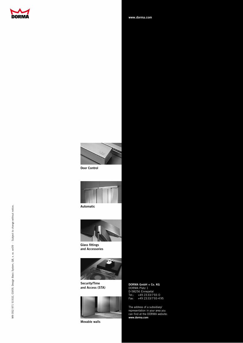
Door Control
Automatic
Glass fittings and Accessories
Security/Time and Access (STA)
Movable walls
WN
05
2 9
71
51
53
2,
03
/09
, D
esig
n B
asic
Sys
tem
, G
B,
x. x
x. x
x/0
9
· S
ubje
ct t
o ch
ange
wit
hout
not
ice.
www.dorma.com
DORMA GmbH + Co. KG DORMA Platz 1 D-58256 Ennepetal Tel.: +49 2333/793-0 Fax: +49 2333/793-495
The address of a subsidiary/ representation in your area you can find at the DORMA website: www.dorma.com