Embed Size (px)
Citation preview

DESIGN ASPECTS AND PERFORMANCE CHARACTERISTICS OF RADIAL FLOW ENERGY DISSIPATORS
by
Khosrow Meshgin Walter L. Moore
Research Report Number l16-2F
Performance of Circular Culverts on Steep Grades
Research Project 3-5-69-116
conducted for
The Texas Highway Department
in cooperation with the U. S. Department of Transportation
Federal Highway Administration
by the
CENTER FOR HIGHWAY RESEARCH
THE UNIVERSITY OF TEXAS AT AUSTIN

PREFACE
The research work presented herein is the final report on Research
Project No. 3-5-69-116, entitled '~erformance of Circular Culverts on Steep
Grades - Part III Exploratory Study of Energy Dissipator for Culvert
Outlets." The authors wish to thank the Texas Highway Department and the
U. S. Department of Transportation Federal Highway Administration for pro-
viding financial support, and The University of Texas Center for Highway
Research for providing general assistance and advice. Special thanks go to
Messrs. Samuel V. Fox, William J. Dallas, and Frank Johnson, staff members
of THD and the Federal Highway Administration, who showed a continuing
interest in the project throughout its duration. The authors wish to
express their sincere appreciation to Dr. Frank D. Masch, Dr. Carl W.
Morgan, Dr. E. Gus Fruh, and Dr. Paul A. Jensen, faculty members, The
University of Texas at Austin, for their comments and critical review of
the manuscript.
Special thanks go to Mr. Edward H. Bruce for his laboratory assis-
tance and model construction. Sincere thanks is expressed to Engineering
students Messrs. Phillip C. Cook, Emede Garcia, and Carlos Vargas for
data collection and reduction, and for drafting assistance. Special
acknowledgment is due to Mrs. Patricia L. Harris for typing and proof-
reading the final manuscript. Finally appreciation is expressed to all
individuals and agencies who were instrumental in the preparation and
completion of this report.
The opinions, findings, and conclusions expressed in this publi-
cation are those of the authors and not necessarily those of the Federal
Highway Administration.
Khosrow Meshgin Walter L. Moore
ii

ABSTRACT
The present investigation was undertaken to explore the feasibility
and performance characteristics of a radial flow basin for use as a flow
energy dissipator, and to develop design concepts applicable to highway
culverts. The radial flow energy dissipator incorporated a vertically
curved drop section which induced radial supercritical flow in a rapidly
flared basin where an arc of a circular hydraulic jump was formed. High
pressures were developed when the flow impinged on the beginning of the
basin floor, thus forcing the flow to spread laterally and stay in contact
with the flared wingwalls of the stilling structure.
Experimental investigations indicated the effectiveness of the
radial flow energy dissipator in stabilizing the jump, reducing the energy
of high-velocity flow, and spreading the flow within the basin. The sensi
tivity of the performance characteristics of the structure to variations in
such parameters as the flaring angle of wingwalls, the ratio of the width of
downstream channel to the culvert diameter, and the height of the drop from
the culvert outlet to thehnrizontal basin floor were explored. Furthermore,
the adaptability of the dissipator to rectangular as well as trapezoidal
downstream channel was investigated.
Based on the experimental results and a semi-analytical treatment
of the hydraulic characteristics of the radial flow basin a design proce
dure was developed which may be followed for the selection of the important
dimensions of a radial flow dissipator under a given set of field conditions.
A simplified form of the circular hydraulic jump equation was obtained
which was the basis for the design procedure.
iii

SUMMARY
This fourth report dealing with a new type energy dissipator for
use at highway culvert outlets includes laboratory measurements of the
hydraulic performance of the dissipator as well as concepts developed for
the design of the culvert and dissipator using the new concept.
The dissipator uses basic physical principles in a new way to
cause the flow from a relatively narrow culvert to be spread in width
as it passes through the structure. The flow can be released at a depth
and width corresponding closely with that of the downstream channel. The
resulting reduction in potential for concentrated local scour that often
occurs at culvert outlets will reduce or eliminate the need for expensive
maintenance that often occurs at such locations. The stilling basin con
tains no obstructions which might catch debris or drift and clog the
structure.
General concepts and procedures are described for determining the
geometric design of the structure, but at the present time this requires
a rather high level of competence in hydraulic theory and designs.
iiia

IMPLEMENTATION STATEMENT
The investigation has shown that the principle of the circular
hydraulic jump can be incorporated into an energy dissipator for cul
vert outlets to produce a structure that appears to be practical and
to have certain advantages over other types of energy dissipators. Its
principle advantages are:
1. The relatively narrow flow as confined by the culvert can
be spread to a width that is compatible with the downstream
channel.
2. The radial flow between the flared walls of the stilling
basin, which resul~s in the formation of a segment of a
circular hydraulic jump, provides stability of the jump
over a range of tailwater elevations.
3. The structure is open at the top and has no barriers to
catch drift or debris and clog the structure.
A one-third scale model of the radial flow energy dissipator
designed for a four by four-foot box culvert operated satisfactorily and
gave some confidence that the concepts and procedures developed for the
design of the structure are valid. In order to implement the knowledge
developed by the research, the following steps should be taken:
1. A site for a field installation should be selected and a
structure carefully designed according to the principles
developed. In building the field installation, provision
should be made for gaining information about the performance
iiib

of the structure without the necessity of having an observer
on the spot. For example, several piezometers located in
the bottom along the centerline of the structure could con
nected to transparent manometer wells treated with cork dust
to record the maximum stage. A periodic check of these mano
meters would indicate the water levels obtained within the
structure. Another suggestion would be to construct a
longitudinal trench one or one-half foot wide and two to
three feet deep immediately downstream from the structure
and fill it with layers of materials selected to have
increasing resistance to the scour. Periodic observations
of this trench would indicate the degree of scour protection
achieved by the structure.
2. The design procedures should be examined more carefully and
more specific directions prepared so the structures can be
designed by personnel with more limited hydraulic experience.
3. An economic study should be made to compare the total cost
of the culvert dissipator system proposed here with that of
alternate types of designs.
4. Under some situations it may be desirable to lead the flow
from a short culvert under the highway into an open trape
zoidal chute leading to an energy dissipation structure
near the bottom of the embankment slope. For these condi
tions, it will be necessary to explore methods for
utilizing the radial flow energy dissipator with the flow
entering from a trapezoidal upstream channel.
iiic

It is believed that the employment of the type of energy dissipa
tor developed here will result in reduced maintenance expense for
correcting problems of local scour at culvert outlets and may result in
less total cost for the culvert dissipator combination than experienced
for other types of designs.
iiid

TABLE OF CONTENTS
PREFACE.
ABSTRACT.
SUMMARY •••••
IMPLEMENTATION STATEMENT .
LIST OF ILLUSTRATIONS.
GLOSSARY OF SYMBOLS. • .
CHAPTER 1
CHAPTER 2
INTRODUCTION
Ob ject ive • . • •
Scope of Investigation .•
ENERGY DISSIPATION .
Height and Length of Hydraulic Jump • •
Location of Hydraulic Jump .•.•••
Conjugate Depths for Different Channel Shapes
Energy Losses in Hydraulic Jump
Existing Energy Dissipators • . • .
Drop Structure - Stilling Basins
Ungrouted Rock - Lined Depression.
Bucket Type Dissipators ••••
Impact Type Energy Dissipators
Saint Anthony Fall Basin .
Radial Flow Dissipator .
Development of Radial Flow Surface Curve Equation •
iv
Page
ii
iii
. iiia
• . • iiib
. . .
vi
viii
1
2
3
5
5
7
8
12
13
13
13
15
18
20
22
25

CHAPTER 3
CHAPTER 4
CHAPTER 5
Page
MODEL CONSTRUCTION AND EXPERIMENTAL RESULTS .. 29
Model Construction. . . 29
Experimental Procedure. 35
Limiting Froude Number Ft for Valid Experimentation. 42
Rectangular Downstream Channel. 45
Stability of the Hydraulic Jump. 45
Velocity Distribution and Reduction. . 52
Water Surface Profile. . . 68
Trapezoidal Downstream Channel. 74
Stability of the Hydraulic Jump. 76
Velocity Distribution and Reduction. 81
Water Surface Profile. . . . .
DESIGN PROCEDURE FOR PROTOTYPE RADIAL FLOW DISSIPATORS.. •.••.•..
88
90
Hydraulic Design of Culverts. • . 91
Width, Height, and the Radius of Curvature of Entrance Channel . . . • • . . . . 92
Stilling Basin Dimensions 101
CONCLUS IONS. . 114
BIBLIOGRAPHY 118
APPENDICES . • . 120
v

Figure No.
2-1
2-2
2-3
2-4
2-5
2-5
2-7
2-8
3-1
3-2
3-3
3-4
3-5
3-6
3-7
3-8 to 3-11
3-12
3-13 to 3-24
3-25 to 3-28
LIST OF ILLUSTRATIONS
Title Page
Definition Sketch for the Circular Jump. 11
Vertical Drop Basin. . . 14
Solid Roller Bucket Type Basin 16
Slotted Roller Bucket. 17
Bradly-Peterka Basin . 19
Contra-Costa Energy Dissipator 19
S. A. F. Stilling Basin. . . . 21
Radial Flow Energy Dissipator. 23
Schematic Layout of Model with Trapezoidal Downstream Channel. . .. ............. 30
Sectional View of Rectangular Channel Basin. 32
Sectional View of Trapezoidal Channel Basin. 33
Photographic View of Entrance Channel and Stilling Basin Layout for Trapezoidal Downstream Channel. . . . . 37
Location of Velocity Measurements for Rectangular and Trapezoidal Channels . . . . . • . . . . . . . . . . . 40
Location of Water Surface Measurements in Rectangular Channel for g 300 and g = 22.5 0 . 41
Froude Number Ft
vs. Pressure. . . . 43
Plot of Y2/ Yt vs. x/Yt for REC Arrangements.
Plot of Y2/Yt vs. Ft
for Arrangement REC 3 .
Velocities in Downstream Channel for REC
. • .48 - 51
53
Arrangements. . . . . . . . . • . ....... 55 - 66
Water Surface Profile of Flow for REC Arrangements ...•.• . • . . . . . . .70 - 73
vi

Figure No.
3-29
3-30
3-31
3-32 to 3-36
4-1
4-2
4-3
4-4
4-5
lA
lB
2B
3B
4B
5B
6B
Title
Water Surface Profile of Flow Along the Centerline of Trapezoidal Downstream Channel (Arr. TRAP 1, 2) ..
Water Surface Profile of Flow Along the Centerline of Trapezoidal Downstream Channel (Arr. TRAP 4) ...
Water Surface Profile of Flow Along the Centerline of Trapezoidal Downstream Channel (Arr. TRAP 5) •••
Velocities in Downstream Channel for TRAP Arrangements . • . . . •
Schematic Representation of Culvert Installation and Dissipating Structure .••.•••••••.•.
A Typical Dissipating Structure with Trapezoidal Downstream Channel Indicating Flow Variables
Graph of F t vs. Yt/R
plot of y vs. Fl· 0
Graph of m vs. r . . 0
Flow Chart for Program Cube.
Typical Highway Culvert Installation and Energy Dissipator . . • . • . ..•
Radial Flow Stilling Basin - Plan View
Radial Flow Stilling Basin - Elevation View.
View of the Transitional Section and the End Sill.
Photographic View of the Model at Balcones Center.
Relative Velocity Pattern in Downstream Channel .•
vii
Page
77
78
79
• .82 - 86
94
97
100
• 103
106
· 123
• 126
130
131
132
• 139
· 142

a r
a'
A c
b'
B
c
C
D
D s
E
g
h
h. J
GLOSSARY OF SYMBOLS
Normal component of acceleration directed toward the center of curvature
Projected length of the edge of triangular converging walls on a horizontal plane
Critical cross sectional area of flow
Cross sectional area of flow before the jump
Cross sectional area of flow after the jump
Width or diameter of culvert, also width of entrance channel
Average width of channel or culvert
Bottom width of the downstream channel
Base length of triangular converging walls, also a constant
Chezy coefficient
Circular pipe diameter
Hydraulic depth on end sill
Specific energy of flow
Energy loss through hydraulic jump
Energy of flow upstream of hydraulic jump
Froude number in a channel
Froude number at the point of tangency of entrance channel
Froude number at the top of entrance channel
Froude number before hydraulic jump
Acceleration of gravity
Piezometric head
Height of hydraulic jump
viii

H
H s
K
L. J
L
L x
m
n
Q
r
r a
Height of drop in drop structure stilling basin
Transitional loss from the radial flow basin to the downstream channel
Height of end sill
Proportionality constant
Proportion of the depth of flow to the center of gravity before the jump
Proportion of the depth of flow to the center of gravity after the jump
Length of the jump
Length of the stilling basin
Distance along the centerline of channel from the leading edge of the jump to the section of velocity measurement
Slope of the curves of Yo vs, Fl
Manning coefficient
Pressure head on flow media
Pressure head on the bed of entrance channel
Hydrostatic pressure forces acting on the sides of a segment of circular jump
Hydrostatic pressure force acting on the upstream section of a segment of circular jump
Hydrostatic pressure force acting on the downstream section of a segment of circular jump
Discharge
Radius of curvature of an element of streamline
Radial distance from the intersection of the flaring wingwalls to the beginning of radial flow stilling basin
Ratio of r2
to rl
Radial distance from the origin of coordinates to the leading edge of a circular jump
ix

R
R c
S c
T
v
v s
x
x
Radial distance from the origin of coordinates to the end of a circular jump
Radius at any point of the radial flow field also, the radius of the vertical curvature of entrance channel
Critical hydraulic radius of flow
Critical slope of flow
Slope of the total energy line
Slope of the channel bottom
Proportionality constant
Average flow velocity, also measured velocity in the downstream channel
Index mean velocity at the beginning of radial flow basin
Mean velocity in the downstream channel
Mean velocity an the end sill
Mean velocity at the top of the entrance channel
Mean flow velocity before the jump
Mean flow velocity after the jump
Distance along the centerline of channel from the beginning of the flared wingwalls to the leading edge of the jump
Dixtance from the reference section to the section of water surface profile measurements
Critical depth of flow
Depth of water standing behind a water fall also, index flow depth at the beginning of radial flow basin
Normal depth of flow
Mean flow depth on end sill
Mean depth of flow at the top of entrance channel
Ratio of Y2 to YI
Depth of flow before hydraulic jump
x

z
z
y
9
Depth of flow after hydraulic jump
Depth of flow in the downstream channel or tailwater depth
Average flow depth in a channel
Elevation of any point with respect to a reference section
Height of drop of entrance channel
Vertical angle of intersection of entrance channel and the horizontal bottom of radial flow basin, also proportionality constant
Specific weight of water
Angle between the flaring wingwalls and the centerline of channel of radial flow basin
Density of water
xi

CHAPTER 1
INTRODUCTION
Drainage culverts under highways are a major source of maintenance
expense in SOllie areas due to the frequent occurrence of scour and erosion
in the vicinity of the culvert outlet. A culvert, because of its hydraulic
characteristics, increases the velocity of flow over that in the natural
channel. High velocities are most damaging just downstream from the cul
vert and the erosion potential at this point is a feature to be considered
in culvert design. Improved methods for reducing this local scour and
erosion will result in considerable reduction in the cost of building and
maintaining highways. Conventional methods of attacking the erosion prob
lem utilize sills, baffles, and impact walls for dissipating the high
velocity energy of the culvert flow. These methods are of limited effec
tiveness, however, because the flow leaving the energy dissipating
structure is usually confined to a narrow stream of about the same width as
the culvert.
The engineer working in a particular area should determine the need
and the type of energy dissipators ,for use at culvert outlets. As an aid
in evaluating this need, culvert outlet velocities should be computed.
These computed velocities can be compared with outlet velocities of alter
nate culvert designs, existing culverts in the area, or the natural stream
velocities. It should be noted that the increased kinetic energy in the
culvert is not the only factor in causing damage in the vicinity of the
culvert outlet, but also an additional cause of the damage is the
1

2
concentration of the flow into a deep and narrow stream of water within the
culvert. The rapid drawdown in the water surface elevation of the concen-
trated flow at the culvert outlet is accompanied by an additional increase
in the kinetic energy of flow. Therefore, the dissipation of excess energy
should be associated with the lateral spreading of the flow to reduce the
flow depth and diminish scour potential at the culvert outlet.
Objective
A new type energy dissipator based on the principle of the circular
hydraulic jump could be designed which is very effective in dissipating
energy and spreading the width of the flow before it is discharged into the
downstream channel. The structure makes use of an abrupt vertical curva
ture to induce radial flow in a rapidly flared basin where an arc of a
circular hydraulic jump is formed. High pressures are developed when the
flow impinges on the beginning of the basin floor. These pressures force
the flow to spread laterally and stay in contact with the flared wingwalls
of the stilling basin.
The new energy dissipator is expected to be especially useful in
regions of steep topography because of the following important advantages:
(1) The flow entering the channel is spread to a width of several times
that of the culvert, thus reducing the flow depth and the concentrated
attack on the downstream channel, (2) the geometry of the basin produces
greater stability of the hydraulic jump thus permitting it to function effec
tively as an energy dissipator over a considerable range of tailwater levels,
(3) the hydraulic jump created in this structure has a shorter length than
that of a comparable parallel flow jump, thus resulting in a reduced length
of the basin, (4) there are no walls or blocks within the basin which

3
would catch drift and impair its operation, and (5) the structure is self
cleaning and there is no danger of debris accumulation within the stilling
basin.
Model studies were undertaken in the present investigation to demon
strate the satisfactory performance of the radial flow dissipator in
stabilizing the jump and reduciDg the high velocity of the flow for a wide
range of geometrical variables. The sensitivity of the performance of the
basin to such variables as the flaring angle of wingwalls in the basin, the
ratio of the width of downstream channel to the width of the beginning of
the basin, and the total height of the drop from the culvert outlet to the
basin floor were explored. Also, the adaptability of a trapezoidal down
stream channel with a transition section from the basin to downstream
channel was studied by model simulation.
Another objective of the research reported herein was to develop a
semi-analytical design procedure for the proper selection of the appropriate
dimensions of such a structure under given set of field conditions. The
field conditions included such features as design discharge, topography,
natural channel dimensions, and highway embankment cross section. The
design procedure was based on the application of the circular hydraulic
jump equation.
Scope of Investigation
Since knowledge of the effectiveness and sensitivity of different
dimensional variables in the performance of radial flow energy dissipator
was a necessity in development of a design procedure, several geometric
configurations of this structure were constructed and tested in the
4
hydraulic laboratory during the course of experimentation. Nine different
configurations of the model were tested. The basic parameters varied in
constructing these geometrical configurations included: the horizontal
0000. angles of wingwalls of 10 , 15 , 22.5 , and 30 ; the ratlos of the width of
the downstream channel to the width or diameter of the culvert of 1, 2, and
4; and the ratios of the height of drop, from the culvert outlet to basin
floor, to the culvert width of 1 and 3. The experiments were performed in
models with rectangular as well as trapezoidal downstream channels. Five
models having a trapezoidal downstream channel incorporated a transition
section and an end sill.
Experimental procedure included determination of the position of
the jump for a wide range of tailwater levels, velocity measurements down-
stream from the hydraulic jump, and water surface profiles of the super-
critical flow within the basin. Velocities were measured at three
different transverse sections in the downstream channel. Water surface
profile measurements were made along radial lines to demonstrate the
efficiency of the spreading action of flow within the basin.
A systematic procedure was developed to enable the engineer to
design an effective radial flow energy dissipator at the outlet of highway
culverts. A simplified circular jump equation was derived and its applica-
tion was the basis for the design procedure. Based on the proposed method,
a prototype structure was designed for a set of known field conditions. A
model having a scale ratio of 1/3 of the suggested prototype structure was
constructed and tested.

CHAPTER 2
ENERGY DISSIPATION
The excessive energy at the outlet of many hydraulic structures
requires some type of energy dissipating device which can modify the energy
of high-velocity flow and prevent or minimize scour, erosion, and under
mining of the structure. This excessive energy could be dissipated by the
internal friction and turbulence or the external energy dissipation by
friction between the contact surface of structure and water.
The basic principle involved in different types of energy dissipa
tors is the conversion of the kinetic energy of flow into turbulent energy,
and ultimately into heat energy. One of the most efficient methods of
dissipating energy is by creation of a hydraulic jump in the flow medium.
Besides dissipating energy the hydraulic jump may increase piezometric head,
extract air from a closed conduit, and increase uplift force.
Since the investigation reported in this research work deals speci
fically with the application of a particular type of hydraulic jump, a
review of the various aspects of this energy dissipating method was made.
Height and Length of the Hydraulic Jump
The height of the jump is defined as the difference between the
depth of water upstream and downstream from the jump. It is designated as:
h j = Y2 - Yl (2.1)
where Yl
and Y2
are the depths of flow before and after the jump
respectively.
5

6
There is not as yet any analytical method to determine the length of
the hydraulic jump, however, some experimental work has been conducted for
a small range of Froude number, using relations between, L/Yl' L/Y2' or
L/(Y2 - Y 1)' and F l' where L. is the length of the jump and Fl is the J
Froude number upstream from the jump. Comparison of the length of hydraulic
jump in different shapes of channel cross section indicates that the short-
est length occurs in the rectangular channel. The existence of a reverse
flow in the sloped sides of channels causes longer jump lengths and more
energy dissipation. The flatter the side slopes the higher the reverse
flow, hence the longer is the jump length.
"k Silvester (1) proposed a general equation expressing the jump
length as follows:
(2.2)
where K and ~ are constants and should be determined experimentally by
plotting graphs of Lj/Yl versus (F l - 1) on logarithmic paper.
USBR (2) developed the following equation for rectangular channel
with Fl < 15:
L. J
(2.3)
Argyropoulos (3) developed a graph for a triangular channel which
yielded:
L. J
(2.4)
* Numbers in parenthesis refer to the similarly numbered items in the Bibliography.

7
Kindsvater (4) proposed the following equation for a circular
section:
L. J
(2.5)
where Y2 ~ pipe diameter.
Rajaratnam (5) stated that although the pressure distribution is not
hydrostatic in the complete body of the jump, the pressure profile on the
bed is essentially the same as the mean water surface profile, except in a
small portion near the toe of the jump where the pressure profile is some-
what higher. On the basis of this statement and through utilization of
existing data and some experimental work, Rajaratnam developed a generalized
profile for the water surface of hydraulic jump in a smooth level rectangular
channel with FI > 4.
Sadler and Higgins (6) proposed an experimental relationship express-
ing the length of the jump for the case of radial hydraulic jump in a hori-
zontal bottom basin. They indicated that:
L. J
(2.6)
where T is a constant having an average value of 4.0.
Location of Hydraulic Jump
The hydraulic jump will form only when pressure plus momentum per
unit time after the jump equals the pressure plus momentum per unit time
before the jump at a distance approximately equal to the length of the jump
between the sections. The pressure plus momentum term consists of two
components. The first component is the momentum of the flow passing

8
through the channel section per unit time, and the second is the total
pressure force acting at the channel section. It is an important design
factor to know where the jump occurs. This can be predicted, within reason-
able limits, depending upon the accuracy with which the friction losses can
be estimated. One method of determining where the pressure plus momentum
quantities are equal within a channel reach is by backwater-curve
computations.
Conjugate Depths for Different Channel Shapes
Solution of conjugate depths for hydraulic jump in rectangular,
triangular, trapezoidal, and parabolic channels may be given in terms of
upstream Froude number. In the case of the radial hydraulic jump, however,
the solution of conjugate depths is given in terms of upstream Froude
number and the ratio of the radial distance from the toe of the jump to the
radial distance from the end of the jump. The radial distance is measured
from the origin of coordinates to the section of jump in question. Usually
in the design of hydraulic jump type energy dissipators the following infor-
mation is sought: The ratio of the conjugate depths, the energy losses, and
the length of the jump.
A general solution begins with the application of the momentum
principle to a horizontal channel bed, neglecting frictional losses,
assuming uniform velocity distribution upstream and downstream of the jump,
and considering hydrostatic pressure distribution. The general momentum
equation in this case is as follows:
(2.7)

9
where
Al Cross sectional area of flow before the jump.
A2 Cross sectional area of flow after the jump.
I
Kl = Proportion of the depth of flow to the center of gravity
before the jump.
K2 Proportion of the depth of flow to the center of gravity
after the jump.
Q Discharge.
g Acceleration of gravity.
and
Froude number before the jump
Through the application of equations 2.7 and 2.8 the following jump
equations are determined:
a)
b)
c)
d)
~ (/1 + 8F 12 - 1) in a rectangular channel
/2)5/2 Yl
I (Y 2)2 K2
Yl
where
b
K
b
2F 2 1
in a triangular channel
- 1 2
'" 2.5F l [1 _ /1)3/ 2 ] Y2
in a first degree parabolic channel
I I
b 2 b l Yl (~) Kl Fl (1 - b ' Y ) b l 2 2 in a trapezoidal channel
average width
lIb -+-.-3 6 b '
::: bottom width.
(2.8)
(2.9)
(2.10)
(2.11)
(2.12)

10
e) A theoretical radial hydraulic jump equation is proposed by Koloseus
and Ahmad (7) as follows:
1 2 2 r - r + 2 + 6Fl 6Fl 3 0 2 0
Y - 2r + 1 Y - 2r + 1 Yo + (2r + 1) o (2.13)
0 0 r 0 0 0 0
The variables shown in equation 2.13 are represented in Figure 2-1.
Koloseus and Ahmad made the following assumptions in deriving the equation
for a sector of an entire radial jump on a horizontal surface: (1) The
liquid is incompressible; (2) the flow is radial and steady; (3) the
frictional shear along all solid boundaries in the region of the jump is
negligible in comparison with other forces involved; (4) the energy coeffi-
cient and momentum coefficient are equal to one; (5) the pressure distri-
bution is hydrostatic before and after the jump; (6) there is no air
entrainment within the jump and the vertical acceleration of fluid is
negligible; and (7) the profile of the jump is straight line. It is note-
worthy that as rl
and r2
approach infinity, ro = 1.0 which corresponds to
a segment of the circular jump with parallel sides. Equation 2.13 then
reduces to the classical jump equation for a rectangular channel:
y = o ~ (/1 + 8F 12 - 1) (2.14)
It should be recalled that all of the conjugate depth equations
were derived on the basis of assumptions that the floor is horizontal, and
frictional losses are negligible. However, in dealing with the hydraulic
jump in steep sloping channels, consideration should be given to the weight
of water when the momentum principle is applied. In channels with mild

11
Q
I
l
/
2
y
x
Figure 2-1 DEFINITION SKETCH FOR THE CIRCULAR JUMP

12
slope, the effect of the weight of water in momentum equation is not appre-
ciable and hence it could be neglected.
Several methods have been attempted to include the frictional losses
in conjugate depth computations, but their effect is usually unimportant,
and they could safely be neglected.
Energy Losses in Hydraulic Jump
The general expression for determining the relative energy losses
for all shapes of horizontal channel is:
V 2 2
EL 1
V2
Yl + - - Y - 2g 2g 2 (2.15)
El + 2 Yl Vl / 2g
where
V average flow velocity,
EL specific energy loss,
El = specific energy upstream of the jump, and
g = acceleration of gravity.
Silvester (1) plotted the energy losses from the above equation for
various channel shapes against Fl
, resulting in graphs of EL/El versus Fl.
It is observed, from these graphs, that all channel shapes (except circular
with Y2 > diameter) give a greater percentage of energy loss than the
rectangular channel for any given Froude number. This difference is due to
the type of velocity distribution pattern and the recirculation of flow on
the sloping sides of the channel.

13
Existing Energy Dissipators
Many types of energy dissipators have been used throughout the
world, and usually the design of each has varied quite radically to meet
the problem at hand. Normally, the dissipation of energy is initiated
within a stilling basin defined as a structure in which all or part of the
hydraulic jump, or any other energy-reducing action, is confined. Several
of these energy dissipating basins are briefly explained as follows:
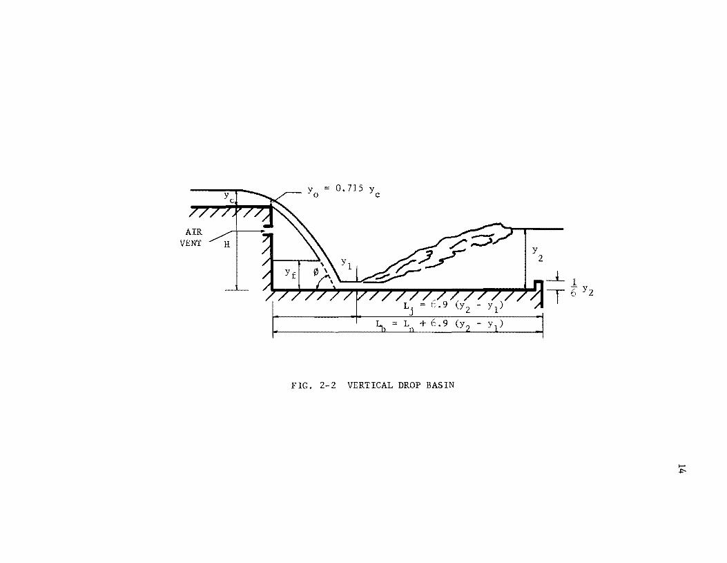
Drop Structure Stilling Basins: A drop structure is sometimes used
to change the slope of a canal from steep to mild. The drop could be verti-
calor inclined, rectangular or trapezoidal and is especially applicable to
steep topography. Figure 2-2 shows a typical drop structure stilling basin.
Experimental investigation by Rand (8) indicated that for vertical drop
basins:
Y2 3.07
Yl ( /H)0.465
and Yc
(2.16 )
Yc [ Y Y
- 3 ] ~ Yf
(----.1:) 2 + 2 (~) Y2 Yf
(2.17)
where
Yc critical depth,
Yf depth of water standing behind the fall, and
H height of drop in the structure.
Ungrouted Rock-Lined Depression: This type of basin is provided at
the outlet of culverts. The basin consists of a depression with an
ungrouted rock-lined bottom having a positive gradual slope at the upstream
portion of the basin and an adverse slope at the downstream portion of the
VENT
y =O.715y o c
Y 2
-Ll ~"'-+""''''''''''''~'''''''''''''''''''''''''''''''''9111111!'''''''''1~ T 6" y 2
FIG. 2-2 VERTICAL DROP BASIN

15
basin terminating to the outlet channel bottom elevation. The ungrouted
bottom permits the complete drainage of the left-over pool after a flood.
The dissipation of energy is accomplished when the culvert flow is
discharged at a downward angle into the basin.
Bucket Type Dissipators: The bucket type energy dissipator is used
when the streambed is composed of rock. Because of a relatively short
length of structure, marked economy is observed in its construction over
many other kinds of comparable structures. The bucket type dissipators are
mostly used at the outlet of large hydraulic structures such as dams with
the primary purpose of either dissipating the energy of flow in the bucket
or to deflect the flow as far away from the outlet of the struct~re as
possible. Some of the more commonly used bucket type energy dissipators
are:
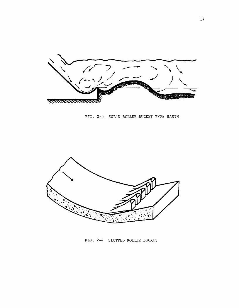
(a) Solid Roller Buckets - The basin consists of a bucket like
apron with a concave, circular profile of large radius, and a
lip which deflect the high-velocity flow away from the stream
bed as shown in Figure 2-3. Energy dissipation results from
the intersection of a ground roller in the bucket and a sur
face roller on the water surface created through the deflect
ing property of the lip of the bucket. The basin has the
disadvantage that at high-velocity flow the material is moved
backward to the bucket and may be trapped and become erosive.
It is mostly used in flood control structures where the
bucket is not in constant contact with water.

16
(b) Slotted Roller Bucket Basin - The slotted roller bucket was
designed to reduce the intensity of violent ground and surface
rollers mentioned in solid roller buckets hence diminishing
the deposition potential of loose material within the bucket.
Figure 2-4 shows a sketch of a typical slotted roller bucket.
The part of the flow which is discharged through the slots is
spread laterally and is lifted away from the channel bottom
downward from the slots. Consequently, the flow is expanded
and distributed over a greater area after passing through the
slots, providing less flow concentration than occurs with a
solid roller bucket.
(c) Trajectory Bucket Basin - When the tailwater conditions are
such that it is difficult to form a satisfactory hydraulic
jump for protection against scouring at the outlet structure
then the flow could be deflected as far as possible from the
end of the structure by the so called trajectory bucket. The
trajectory bucket basin forces the jet of water to leave the
stream-bed by deflecting its direction upward, creating a
trajectory impacting with the stream-bed at some distance
downstream from the end of the basin. In this type of basin
the elevation of the bottom of the bucket is usually higher
than the stream-bed elevation.
(d) Tunnel Deflectors - Tunnel deflectors are utilized to deflect
the high-velocity flow as far as possible away from the tunnel
outlet. They are constructed in areas where the stream-bed
17
--~~-----~~-~~---------~--~---~-------~,
FIG. 2-3 SOLID ROLLER BUCKET TYPE BASIN
FIG. 2-4 SLOTTED ROLLER BUCKET

18
below the tunnel is composed of firm rock which can resist
scour damage. Generally, the operation of tunnel deflectors
should be confined to emergency or infrequent use.
Impact Type Energy Dissipators: This type of dissipator is used
for a flow with specific energy in excess of 2D (where D is the outlet
pipe diameter at basin1s entrance). The dissipator is constructed in such
a manner that all or most of the flow is forced to change direction locally,
and then discharged in the original direction into a concrete basin. Two
well known impact type energy dissipators are Bradly-Peterka (9) and
Contra-Costa (10) basins.
(a) Bradly-Peterka Basin - This basin is only effective when Fl
is greater than three in which the entire flow impacts with a
hanging baffle installed in the basin. Energy dissipation is
initiated when the flow strikes the vertical hanging baffle
and changes its direction. A sketch of Bradly-Peterka basin
is shown in Figure 2-5. This structure requires no tailwater
for its effective operation in dissipating the energy
although sufficient tailwater depth may improve the perfor
mance of the basin by reducing the outlet velocities.
(b) Contra-Costa Energy Dissipator - This dissipator consists of
a trapezoidal basin with two impact walls across it as shown
in Figure 2-6. The upstream impact wall has a height which
is half as much as the height of the downstream wall. The
least desirable feature of this stilling basin occurs when the
entering flow into the basin is completely submerged by the

19
FIG. 2-5 BRADLY - PETERKA BASIN
FIG. 2-6 CONTRA-COSTA ENERGY DISSIPATOR

20
tailwater. Debris accumulation within the basin may be anti
cipated for certain discharge conditions.
Saint Anthony Fall Basin: Principally, the SAF basin has been used
for drainage structures where relatively small quantities of flow are
expected. The dissipation of energy is accomplished through the formation
of a hydraulic jump within the basin. Through the addition of stilling
basin appurtenances the SAF basin can considerably reduce the length of
the conventional hydraulic jump type stilling basins. Figure 2-7 shows
the general configuration of the SAF basin. The component parts of this
basin are:
1. a steep chute, with chute blocks at its downstream end,
2. a trapezoidal apron with baffle blocks,
3. an end sill which extends for the full width of the basin, and
4. the basin training walls which may be parallel or divergent.
It should be noted that in most of the basins discussed so far, the unde
sirable characteristic is debris accumulation, especially in impact type
energy dissipators.
Several other special stilling basins are in use throughout the
world which have performed very satisfactory for their intended purpose.
Elevatorski (11) compiled the description of some of the more commonly
known of these basins such as: sluiceway stilling basin, jet-diffusion
basin; free-jet basin; and Bahavani stilling basin. Modified shapes and
dimensions of stilling basin appurtenances such as chute blocks, baffle
blocks, and end sills have been used to improve the performance and to
reduce the length of the basin. An example of this type of modification

.11'
<
.. -
Half - Plan
I~ L
B/3 "I
I lD
I [[J
I _ B
l __ -- - -- - - [B---
I
I [[]
I []
11 n'
Centerline Section
Side Wall
-
21
"V(50
, '.'
-
~
\ \ \ \ \
\ \
Cut-Off Wall ~ , _ ... _..1
FIG. 2-7 SAF STILLING BASIN

is the Bahavani stilling basin in India which utilized T-shaped floor
blocks.
22
Radial Flow Dissipator: The original laboratory experimental inves
tigations of a radial flow energy dissipator was conducted by Aguirre (12).
In this dissipator the culvert flow dropped along a steep chute, which
ended at its intersection with the horizontal bottom of the stilling basin.
As the flow impinged on the horizontal bottom, it was forced to spread
rapidly, thus avoiding separation from the flared wingwalls. In this pro
cess the flow was changed from parallel to radial flow, and again to
parallel flow in the downstream channel.
The combination of this supercritical radial flow and the required
tailwater depth resulted in the formation of a hydraulic jump whose leading
edge was approximately a circular arc. The required tailwater for such a
hydraulic jump could be substantially varied while the location of the
jump itself varied over a relatively short distance. Figure 2-8 shows a
general sketch of a Radial Flow Dissipator. The geometric parameters used
in the design of this dissipator were:
b width of entrance channel,
B width of downstream channel,
L projected length of flared wingwalls on a plane parallel to
the centerline of the channel,
Z height of drop of curved channel section,
~ deflection angle between the tangent to the downstream end of
the curved channel section and the horizontal bottom basin,
and
Q angle between the flaring wingwalls and the centerline of
the channe 1.

23
T B
b
Plan
_i Elevation
FIG. 2-8 RADIAL FLOW ENERGY DISSIPATOR

24
Aguirre conducted experiments on eight different geometric arrangements of
this energy dissipator which included Bib ratios of 4 and 6 and G values
of 30 and 45 degrees.
Wear (13) investigated by model simulation, the effect of a partial
transverse sill or an abrupt rise, located near the downstream end of the
apron of a radial flow basin, on the performance of this type of dissipator.
He reported on the hydraulic performance of radial flow basins independently
incorporating four different rise heights, two sill locations, and sills
with or without 450
beveled face. Wear concluded that an abrupt rise as
part of a radial flow energy dissipator permitted efficient operation of
the basin with low values of downstream tailwater depth. Furthermore,
significantly lower values of tailwater depth were required to stabilize the
jump within the basin as the rise height was increased.
The adaptability of radial flow energy dissipator for use with cir
cular or box culvert was further explored by Moore and Meshgin (14), who
investigated the performance of the basin with some modifications of the
shape of the curved-drop channel such as a "V" shaped cross section and
sloping of the flaring wingwalls backward in order that they were contin
uation of the two planes forming the "V" section at the bottom end of the
drop. The possibility of eliminating the curved drop and replacing it with
a simple vertical wall was also studied. Although this arrangement per
formed well when the falling jet impinged on the apron in the proper place,
an increase in Froude number caused the impingement point to shift down
stream resulting in very unsatisfactory performance. It was concluded from
this investigation that the relative simplicity of construction was a
strong argument in favor of the structural arrangements with the simple

25
curved drop and straight horizontal elements incorporating a box or a
circular culvert.
Aguirre, Wear, and Moore all concluded that the radial flow energy
dissipator stabilized the jump, reduced the outlet velocity, and permitted
efficient operation of the basin over a high range of tailwater variations.
Development of the Radial Flow Surface Curve Equation
An equation for free surface radial flow was originally developed
by Davis (15) and later it was slightly revised by Sadler and Higgins (6).
The basic approach to the development of this equation was through the
application of the specific energy relationship in open channels and the
use of classical Chezy equation to evaluate the average channel velocity.
The derivation of the radial flow surface curve by Sadler and Higgins (6)
is as follows: E
2 Y + V /2g (2.18)
Assuming that the hydraullc radius is equal to the depth of radial flow
and the head loss at a section is the same as for uniform flow, the Chezy
equation becomes:
(2.19)
where
E specific energy of the flow,
V mean velocity of the flow,
C Chezy coefficient,
Y depth of flow at distance R, and
Sf slope of the total energy line.
Differentiating equation (2.18) with respect to R yields:

dE dR
dY V -+dR g dV dR
The total specific energy at any subsequent cross section is:
E
where
R radius at any point of the radial flow field, and
S slope of the channel bottom. o
Differentiation of equation (2.21) results in:
dE dR
Equating equation (2.20) and (2.22):
dE dY V dV dR dR + g dR
From continuity principle:
hence,
V ~ 2nRY
dV = ~ (1. + 1. dY) dR 2nRY R Y dR
26
(2.20)
(2.21)
(2.22)
(2.23)
(2.24 )
(2.25)
Direct substitution of equations (2.19), (2.24), and (2.25) in equation
(2.23) results in:
dE dR
s o 4
2 2 2 3 c n R Y
Introducing the Froude number as:
dY dR 222
4n R Y g (2.26 )

into equation (2.26) and solving for dY/dR.
or
S + F2 (-::&z + ~) ocR
dR 1 _ F2
dy - == S + -,,-:=--dR 0
(..£. _ s - X) C2 0 R
27
(2.27)
(2.28)
(2.29)
For horizontal channel bottom (8 = 0) and frictionless flow condition o
(g/c2
= 0) equation (2.29) becomes:
dY dR
2 2 When F » 1.0 then F /(F - 1) approaches unity and hence,
or
integrat ing:
dy = dR
Y R
dY dR -:= -
Y R
(2.30)
(2.31)
(2.32)
(2.33)
After introducing boundary conditions the solution of equation (2.33)
Ids:
(2.34)
where YI
and RI are known flow depth and radius respectively.

28
Equation (2.34) indicates that constant velocity prevails every-
where within the radial flow field if the assumptions made in its derivation
hold true.
In the case of flow with boundary friction, high Froude number
(Fl
» 1.0), and constant C, Davis (15) derived the following radial flow
surface curve:
(2.35)

CHAPTER 3
MODEL CONSTRUCTION AND EXPERIMENTAL RESULTS
Model Construction
The experimental work was conducted in the Hydraulic Laboratory of
the Civil Engineering Department of The University of Texas using an
apparatus similar to the one used by Aguirre (12) and Wear (13). The
schematic layout of this apparatus with trapezoidal downstream channel is
shown in Figure 3-1. Certain improvements were made in the previous struc-
tural arrangement for better performance of the model such as utilization
of a large head tank open at the top and containing several transverse
screens and baffles to damp out the flow disturbances from the supply pipe.
A horizontal circular culvert, six inches in diameter and three feet long,
conveyed the water from the stilling tank to a six inch wide rectangular
channel. The six inch rectangular section is referred to as an entrance
channel throughout this report. The circular culvert was formed from a
piece of aluminum sheet metal rolled to a 0.5 foot diameter. The sheet
metal was rolled in such a manner that it formed a butt joint held in
place with tape and placed at the top of the pipe thus preventing any
possible leakage. An adjustable sluice gate installed at the upstream end
of the pipe controlled the depth of flow in the model culvert.
The connection from the circular conduit to the entrance channel
was a sudden expansion. The entrance channel had a vertically curved bot-
o tom with a tangent section intersecting at a 60 angle with the horizontal
bottom of the stilling basin. The radius of curvature of the curved
29

Baffles and Filters
Sluice Gate
Circular Culvert
Entrance Channel
Stilling and Control Tank
Converging Wall
Sloping Sides
Exit Channel
Control Gate
FIG. 3-1 SCHEMATIC LAYOUT OF MODEL WITH TRAPEZOIDAL DOWNSTREAM CHANNEL

31
section of entrance channel was nine inches. The stilling basin was a di
verging structure with six inch upstream width and flaring vertical wing
walls setat various horizontal angles which terminated to either a
rectangular or a trapezoidal downstream channel.
The downstream channel was 8.5 feet long as measured from the begin
ning of the flared wingwalls along the channel centerline. This was 3.0
feet longer than the downstream channel used by Aguirre and Wear which
helped to minimize any possible influence of the downstream control gate on
the flow conditions in the model. A six inch flap gate at the end of the
downstream channel controlled the tailwater depth.
The required flow for the experiments was supplied through a low
head pump from the laboratory sump directly into the laboratory distribu
tion system. Flow was regulated by a three inch gate valve and measured by
a calibrated-in-place three inch elbow meter. A precision differential
water manometer with a vernier reading to the nearest 0.001 foot was used
to determine the piezometric head difference from the elbow meter.
Several geometric configurations of the model were constructed and
tested during the course of experimentation. Three basic parameters were
altered in constructing different configurations of the model. These
parameters were the horizontal angle of the flaring wingwalls, the bottom
width of the downstream channel, and the drop height of the entrance
channel. The experiments were performed in models with rectangular as well
as trapezoidal downstream channels. The schematic representation of the
rectangular and trapezoidal channel models are shown in Figures 3-2 and
3-3 respectively.

Receiving __ - Channel
Entrance Channel
,.-_-- Wing'Wal1
Basin Floor
FlG. 3-2 SECTIONAL VIE" oF RECfANGULAR CHANNEL BASIN

conver:ging Wall
Sloping Side
Basin Floor
End Sill
Channel Bottom
FIG. 3-3 SECTIONAL VIEW OF TRAPEZOIDAL CHANNEL BASIN

The model with rectangular downstream channel incorporated the
following dimensional variations: The ratios of the width of entrance
channel to the width of the downstream channel were two and four; the
000 flaring wingwalls were set at horizontal angles of 10 , 15 , 22.5 , and
300 measured with respect to the channel centerline. The height of the
drop of entrance channel was six inches in all geometric arrangements.
In the case of the trapezoidal downstream channel the following
modifications were made to observe the performance characteristics of
34
different structures: The ratios of the bottom width of downstream channel
to the width of entrance channel were one and two. The flaring wingwalls
had 300
horizontal angles measured from the channel centerline. The length
of the stilling basin along the channel centerline was twenty-six inches.
The downstream channel side slopes were 2:1 in all structures. Two abrupt
rises, 0.75 inch and 1.50 inches in height, were constructed at the end of
the stilling basin. Two different drop heights of the entrance channel
were used for this model, six inches, and eighteen inches.
The transition from the stilling basin to the trapezoidal down-
stream channel consisted of a pair of converging triangular walls. The
base of each converging wall was located on the stilling basin bottom and
its apex was fixed at the point of intersection of the flared wingwalls and
the side slopes of the trapezoidal channel. The surface area of each wall
was changed by either decreasing or increasing the wall's base length.

Experimental Procedure
Nine different geometric configurations of the model were tested
to demonstrate the efficiency and performance of the energy dissipating
structure. As stated previously, the geometric parameters varied con-
sisted of 9, Bib, ss, H , clb, and Z, where 9, Bib, and Z were defined s
previously, and
ss side slopes of the downstream channel,
35
H sill height of the end of the stilling basin in inches, and s
clb ratio of the base length of converging walls to the width
of the entrance channel.
The combination of different geometric parameters used in the model
and the designation given to each one are indicated in Table 3-1. A photo-
graphic view of the entrance channel and the stilling basin layout for a
trapezoidal downstream channel is shown in Figure 3-4.
Jump stability, velocity distribution, and water surface profile
measurements were made to determine the nature and degree of the spreading
action, energy dissipation, and performance of the basin. Radial water
surface profile measurements were obtained within the stilling basin in the
case of the rectangular downstream channel. For the trapezoidal channel
model the profile measurements were only recorded along the centerline of
the channel.
The stability of the hydraulic jump was determined in terms of the
longitudinal movement in jump position as the result of variation in the
tailwater depth. The position of the jump was defined by the distance
along the basin centerline from a section at the beginning of the flared
wingwalls to the leading edge of the jump.

TABLE 3-1 DESIGNATION AND CHARACTERISTICS OF VARIOUS GEOMETRIC ARRANGEMENTS
It,deg. B Side Hs,in. c/b Z,in. Ft b Slope Yt Y1 Y2 r 1
*REC 1 10 2 vert. 0.0 6 2.56 0.225 0.490 1. 82 0.510 2.42 0.480 2.92
3.125 0.211 0.619 1.82 0.528 2.42 0.510 2.92
REC 2 15 4 vert. 0.0 6 1.12 0.306 0.519 1.33 0.461 1.93 0.414 2.43
2.56 0.225 0.489 1. 33 0.414 1.93 0.368 2.43
REC3 22.5 4 vert. 0.0 6 2.01 0.257 0.453 1.01 0.416 1.61 0.363 2.11
1.91 0.278 0,460 1.01 0.403 1.61 0.367 2.11
2.56 0.225 0.441 1.01 0.412 1.61 0.356 2.11
1.86 0.302 0.486 1.01 0.460 1.61 0.402 2.11
REC4 30 4 vert. 0.0 6 1.11 0.314 0.532 0.83 0.458 1.43 0.377 1. 93
3.125 0.211 0.724 0.83 0.523 1.43 0.414 1.93
2.56 0.225 0.407 0.83 0.360 1.43 0.325 1.93 0.424 1>.83 0.414
**TRAP 1 30 1 2:1 2.25 2.25 6
TRAP 2 30 1 2:1 0.75 2.50 6
TRAP 3 30 2 2:1 0.75 2.50 6
TRAP 4 30 2 2:1 0.75 1.80 6
TRAP 5 30 2 2:1 1.50 L=:l 18
* "REC" indicates rectangular downstream channel. ** "TRAP" indicates trapezoidal downstream channel.
2.56 0.225
2.56 0.225 0.115 O. 395/~ 1.86 0.302 0.170 0.40511
2.56 0.225
2.56 0.225 0.109 0.293/~
1.86 0.300 0.083 0.313/~
1.86 0.260 0.235 O. 353/~
NOTE: (1) Values marked IF are influenced by the sill, and therefore may not agree with a calculated value.
0.83 0.83
1.13
1.73 0,83 1.23 1.58
1.73
(2) YI can be obtained by applying the continuity and energy equations based on known values of Ft and Yt.
36
4.' 2
2.62 3.42 3.92 3.22 3.42 4.42
2.11 2.51 3.01 2.11 2.56 3.01
2.43 2.43
2.13
2.63 1.83 2.23 2.58
2.63

37
(a) With Flow
(b) Without Flow
FIG. 3-4 PHOTOGRAPHIC VIEW OF ENTRANCE CHANNEL AND STILLING BASIN
LAYOUT FOR TRAPEZOIDAL DOWNSrR~~ SECTION

38
The position of the jump was determined through the application of
a Lory type point gage mounted on a rigid carriage instrument which could
be easily moved back and forth in the longitudinal as well as transverse
directions. The point gage was placed along the basin centerline over the
leading edge of the jump. A calibrated tape, placed on a longitudinal
track, facilitated the determination of the position of the leading edge
of the jump with respect to the reference section. Since constant fluct
uations of the leading edge of the jump could not be prevented, a visual
temporal average for each reading was recorded as the jump position in
each test run.
A piezometer was placed at the beginning of the stilling basin
bottom along the centerline of the channel. This piezometer could deter
mine the pressure variations of the flow at the entrance of the stilling
basin. A flexible plastic tube connected the piezometer to an open
manometer. The pressure readings obtained at this section were especially
helpful in determining the limiting Froude number at which the flow would
spring free from the bottom of the entrance channel.
The control of the jump position at various sections was accom
plished by means of a six inch flap gate placed at the end of the down
stream channel. The flap gate was used to increase or decrease the
tailwater depth thus changing the position of the jump. Tailwater depth
measurements were made by means of the previously mentioned point gage
which was used to locate the jump position.
Velocity measurements were obtained for the purpose of ~dicating
the efficiency, the spreading action, and the degree of velocity reduction

39
in the jump. A Pitot tube mounted on a sliding carriage was used for
velocity measurements. The Pitot tube was placed parallel to the channel
centerline and measured the velocity head at 0.03 foot and 0.4Y2 from the
bottom of the channel. The flow velocity on the sloping face of the trape
zoidal downstream channel was measured as close to the bottom as possible.
Prior to making the velocity measurements, a discharge with a suitable
Froude number was selected and provided for the test run under consideration.
The hydraulic jump was then stabilized at three different positions for
rectangular downstream channel set up, located at x = 0.4 ft., x = 1.0 ft.,
and x = 1.5 ft., where, x was the distance along the centerline of channel
from the beginning of the flared wingwalls to the leading edge of the jump.
In trapezoidal downstream channel model, the converging walls and the
abrupt rise acted as a contraction which forced the jump to form within the
stilling basin independent of the tailwater depth.
The Pitot tube used during the course of this investigation was
connected to a differential water manometer, the accuracy of which was to
the nearest + 0.001 ft. Figure 3-5 shows the typical location of velocity
measurements for the rectangular as well as the trapezoidal models.
In order to study the degree of angular uniformity and the effect
of the flaring wingwalls on the spreading action of the supercritical
flow in the basin, water surface profiles were determined along radial
lines by direct measurement of water depth within the basin. Typical
location of these radial lines are shown in Figure 3-6. A Lory type "A"
point gage resulting in readings to the nearest + 0.002 ft. was used to
measure the depth of water. The radial lines used as reference were the

2.50 1
2.00' 1.50 1
x ~
-C) -0 ...j"
0
0 ...j"
Ci . 0
>:Q --0 ...j" . 0
\ 0 ...j"
Lead Edge of 0
Hydraulic Jump ')
~ Points of Velocity Measurement (a) Bib == 4.0
Rectangular Section
4.00' 3.00'
2.20'
Hydraulic Jump
(b) Bib = 2.0
Trapezoidal Section
FIG. 3-5 LOCATION OF VELOCITY MEASUREMENTS FOR RECTANGULAR
AND TRAPEZOIDAL CHANNELS
40

\ \ \
\ \
bI ~}: ~~-------+---' " , ,
I I I
(a) ~ = 4, 9 = 30°
==:::-___ I I I
(b) B b
4, 9
41
B --
-B--
FIG . 3-6 LOCAT ION OF WATER SURFACE MEASUREMENT S IN RECTANGULAR CHANNEL ° 0 FOR 9 = 30 and 9 = 22.5

42
centerline and several s~netrical lines. The s~netrical lines for 9
300 were set at 100, 200
, and 300
from the channel centerline; for 9
000 0 000 0 they were set at 5 , 10 , 15 , and 22.5 ; for 9 ~ 15 at 5 , 10 , and 15 ;
a a a and for 9 ~ 10 at 5 and 10 .
Along the wingwalls an oscillating high wave was formed which
caused a decrease in the accuracy of the depth reading to ± 0.003 ft. As
the supercritical flow advanced downstream into the rectangular channel,
some shock waves were formed which reduced the accuracy of depth reading
to + 0.01 ft. The shock waves are usually found in supercritical flow in
channels of no n linear alignment or non prismatic sect ion.
Since the general configuration of the trapezoidal section was such
that the jump was formed primarily due to the contraction in the stilling
basin with hardly any tailwater requirements, the radial profile of the
supercritical flow was not determined for this configuration. The
hydraulic jump in this case was normally formed close to the beginning
section of the flared wingwalls within the basin. A noticeable increase
in the tailwater depth forced the jump to move upstream and eventually
submerged it.
Limiting Froude Number Ft for Valid Experimentation
Several undesirable characteristics were observed when the Froude
number (F t ) exceeded a certain limit. One of the most important of these
characteristics is indicated in the graph of pressure at the beginning of
the stilling basin vs. Froude number at the entrance channel in Figure 3-7.
Study of this graph indicated that when Ft
was increased to 2.56 for the
geometrical arrangement which was tested, there was a sudden decrease in

43
0 .6 Ci r cula r Cu lvert
Bi b = 2 c: Q = 100 .... '" Z = 611
<II 0 . 5 '" '" .s= ....
"-' 0
bO c: .... 0 . 4 ~
c: .... bO
" '" '" .s= .... .... 0. 3 OJ
... '" .... OJ ~
"-' 0
.... 0 . 2 '" '" '" c: ....
'" ... ~
'" '" 0 .1 '" ... '"
O ~. ______ ~ ______ ~ ______ ~ ______ ~
1. 0 2. 0 4. 0 5. 0
"fIG. J - 7 FROUDE NUMIlER Ft
vs . PRE SSURE

44
pressure quickly approaching atmospheric or zero gage pressure. This was
attributed to the fact that above this limiting Ft
, separation between the
flow and channel bottom at the downstream portion of the entrance channel
took place. This separation of flow defeated the purpose of proper design
of the curvature of entrance channel. It was expected to have a negative
pressure beneath the nappe when separation of flow occurred. In this case,
however, when the separation occurred the overfalling jet was completely
aerated; that is, the upper and lower nappe surfaces were subject to full
atmospheric pressures. The negative pressure would be only due to the
removal of the air from underneath the nappe by the overfalling jet. For
other design values of Ft
proper dimensions of the structure could be
determined to avoid any serious problem. Another undesirable feature of
high Ft
in this experiment was an extremely rough surface which occurred
on the flow because of sudden expansion from the circular conduit to the
rectangular entrance channel. This factor affected the degree of uniformity
of the supercritical flow in the stilling basin.
Because of the above mentioned features) the range of valid experi-
mentation was limited to Ft
of less than or equal to 2.56 when value of Z
was six inches. A graph similar to Figure 3-7 for a Z value of eighteen
inches showed a limiting Ft
of 2.25. It should be noted, however, that
higher Froude numbers (Ft
) could be used if the design of the curvature of
the entrance channel is changed to suit the particular range of F in mind. y
The design of the curvature of entrance channel is dependent upon the mag-
nitude of the allowable negative pressure on the bed of entrance channel
and its detailed procedure is outlined in the next chapter. Previous
experimental work showed that higher limits of Ft
could be tolerated if a
box culvert was used instead of the circular pipe when the dimensions of
the entrance channel were unchanged.
45
Discussion of the performance characteristics and factors influenc
ing basin design is treated separately for rectangular and trapezoidal
downstream channel models to prevent complications in the analyses of the
results. An overall comparison of the two models would be made with
special emphasis on advantages or disadvantages of each model after they
are discussed separately.
I - Rectangular Downstream Channel
Three basic performance characteristics are of interest in the
study of rectangular downstream channel basins. These characteristics are
the degree of stability of the hydraulic jump, the degree of velocity
reduction when flow passes over the basin, and the general appearance of
water surface profile. A detailed study of each one of these factors is
followed:
Stability of the Hydraulic Jump: The criterion chosen for deter
mination of the stability of the jump was the change in the position of
the jump when flm, condition was subject to a change in tailwater depth
keeping all other parameters constant. The position of the jump was indi
cated by distance x, where x was the distance along the centerline from
beginning of the basin to the leading edge of the jump. An increase in
tailwater depth corresponded to a decrease in the magnitude of x, and a
decrease in tailwater depth corresponded to an increase in the magnitude
of x.

46
\~en the tailwater continued to increase, the hydraulic jump moved
upstream until the jump was completely submerged. After the jump "as sub-
merged, a further increase in the tailwater depth did not affect the posi-
tion of the jump. On the other hand, if the tailwater depth continued to
decrease, it reached a value in which the jump was completely eliminated.
When the jump was eliminated a series of shock waves appeared on the
downstream channel. Therefore, the effectiveness of this type of geometric
arrangement was dependent upon an upper and lower limits of the tailwater
dep th.
Experimental as well as analytical investigations of this type of
basin configuration revealed that the required depth of tailwater to stabi-
lize the hydraulic jump at a certain position (x) depended on Vt
, Yt' and g.
Where, V and y were the mean velocity and the depth of flow at the up-t t
stream end of the entrance channel respectively, and g was the acceleration
of gravity.
These variables were combined to obtain the dimensionless para-
meters Y2/ Yt' x/Yt' and Ft· Ft is the Froude number at the upstream end of
the entrance channel, and Y2 is the sequent depth of the hydraulic jump.
The computation of Ft
was based on the mean velocity of flow at the end of
the circular conduit. The mean velocity was determined by using Yt as the
depth of flow inside the circular conduit. The dimensionless parameters
Y2/ Yt' x/Yt' and Ft are especially advantageous in the analysis of results
and the graphical representation of the variables.
Experimental procedures established for the study of the stability
of the hydraulic jump required determination of the functional relation-
ships between YZ/y and x/y for constant values of F and y lb. These t t t t

functional relationships are presented graphically on plots of Y2/ Yt vs.
X/Yt for a given Ft
in Figures 3-8 through 3-11. Different values of Ft
were selected ?y either changing the discharge and keeping Yt unchanged,
or by keeping the discharge unchanged and varying Yt'
47
The degree of the stability of hydraulic jump at any given section
of the basin is indicated by the slope of the curve of Y2/ Yt vs. x/Yt at
that section. The slope of the curve could be determined from a tangent
to the curves at the intended section. Study of the general pattern of
these curves indicated that as x/y increased the slope of the curve t
decreased until it became nearly horizontal. It should be noted that the
stability of the jump was directly related to the absolute value of the
slope of the curves of Y2/ Yt vs. x/Yt' The higher the absolute value of
the slope the more stable was the jump position. Furthermore, it was inter-
esting to note that, within the stilling basin the absolute value of the
slope was quite high. As soon as the jump moved downstream outside the
region of wingwalls, the magnitude of slope decreased rapidly approaching
zero. This pattern of variation in the absolute value of slope was an
indication of the effectiveness of the basin and flaring wingwalls in
stabilizing the jump. The position of the end of the wingwalls was marked
in every curve for the purpose of comparing jump stability within the basin
and downstream from the basin. Analyses of these curves also indicated
that when the jump moved downstream, leaving the stilling basin, the slope
of the curve did not immediately reach its limiting low value. This was
an indication of the radial flow effectiveness in stabilizing the jump even
when it was moved outside the basin. Of course, this stabilizing effect
did not continue to exist if the jump continued moving downstream.

48
3 .5 r--------------------------------------------,
3.0
End of Wingwalls
2.5
2.0 2.56 3. 125
1.5
1.0 o 5 15 20
FIG. 3-8 PLOT OF Y2/Yt
vs. x/Yt
FOR ARRANGEMENT REel

2.5
2.0
1.5
1.0
0.5
o o 5 10
x/y t
15
End of Wingwa 11s
F t
2.
FIG. 3-9 PLOT OF Y2/Yt vs. x/Yt FOR ARRANGEMENT REC2
49
20

2 . 5
2.0
1.5
1.0
0.5
End of Wingwalls
Ft~ 2.56
~ 2 .01 1. 91
o~--------~--------~--------~--------~ o 5 10 15 20
FIG. 3- 10 PLOT OF Y2/Y vs. x/y FOR ARRANGEMENT REC) t t
50

51
2.5
2 .0
End of wingwalls
1.5 a = 0.0
Y2/ V , t 2.56
l.0
0.5
O~ ______ ~ ______ ~~ ______ ~ ______ ~ o 5 10 15 20
FIG . 3-11 PLOT OF Y /y vs. x/y FOR ARRANGEMENT REC4 2 t t

52
Eventually, at some point in the downstream channel the jump was com-
pletely eliminated.
In order to investigate the effect of Froude number (Ft
) on the
stability of hydraulic jump a graph of Y2/ Yt vs. Ft
was prepared as shown
in Figure 3-12. The values used in plotting the curves of this figure
were interpolated from the curves of Figure 3-10 and should not be inter-
preted as original data. The most effective range of F , resulting in a t
large variation of Y2/ Yt for constant values of x/Yt
, occurred when Ft
was
smaller than 2.0. Since this effective range of Ft
was only investigated
in arrangement REC 3 a general statement with regard to its importance
cannot be made at this time. On the other hand, examination of Figures
3-8 to 3-11 indicated the effectiveness of Ft
on jump stability. As
shown in these figures, the absolute slope of the curves within the basin
Increased as Ft
decreased for a given position of the jump.
The comparison of the relative jump stability characteristic of
each geometric arrangement tested in this experimental study could be made
from the curves of Y2/ Yt vs. x/Yt' So far as the stability criterion was
concerned, arrangement REC 3 appeared to be the most effective basin fol-
lowed by arrangement REC 4. Arrangement REC 1 was not particularly suit-
able for radial jump energy dissipation as it did not provide sufficient
expansion of flaring wingwalls which in turn limited the opportunity for
full radial flow development.
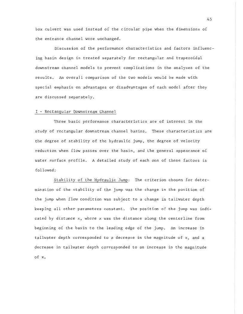
Velocity Distribution and Reduction: Velocity measurement were
obtained at 0.03 foot and 0.4 Y2 from the channel bottom at the downstream
channel to determine the transverse velocity distribution and gain some

2.5 --0-- x/Yt 2
---l::r- x / Y t 4
--D-- x/Yt = 6
--0- x/Yt = 8
2.0
1.5
1.0
0.5
O~--------~----------~ __________ ~ __________ ~ 1.0 1.5 2.0
F t
2.5
FIG. 3-12 PLOT OF Y2/Yt
vs. Ft
FOR ARRANGEMENT REC3
3.0
53

54
knowledge of the degree of velocity reduction within the basin. The proce-
dure followed in making the velocity measurements was to set the flow at a
particular Froude number (Ft
) and stabilize the position of the jump by
adjusting the tailwater depth. Three different jump positions were tested
in each experiment. The leading edge of the jump for these positions was
set at 0.4, 1.0, and 1.5 ft. from the beginning of the flaring wingwalls.
The transverse sections downstream from the jump at which the velocity
measurements were made are indicated by the distance x + L. Parameter x x
was defined previously and L was the distance along the centerline of x
channel from the leading edge of the jump to the section at which velocities
were measured. Distance x + L is shown in Figures 3-13 through 3-24. The x
relative importance of velocity at each section in these figures is indi-
cated by a dimensionless parameter, V/V. The plotted velocities were m
measured at three different transverse sections. These figures facilitated
the comparison of general pattern and magnitude of velocities for a given
Ft
and a fixed jump position. The measurements of velocity were obtained
for Ft
equal to 1.12, 1.86, and 2.56.
It should be noted that in all velocity measurements the Pitot
tube was placed in a longitudinal direction parallel to the channel
centerline. Therefore, the measured velocities at Some points could have
been slightly lower than the actual velocities. Within the center section
of the channel the velocity direction was nearly parallel to the Pitot
tube and the measured velocities in this region coincided with actual
velocities. In regions close to the channel walls, however, some discre-
pancy from the true velocity was expected. This discrepancy was not
appreciable for the purpose of this experimental work and could be safely
neglected.

-
-
, !l
Leading edge of the Jump
, ~
Leading Edge of the Jump
1. 12 55
Pitot Tube at 0.03'
x + L 1.5 2.0 2.5 3.0 3.5
v/V
x
m o o 2
Pitot Tube at 0.4 Y2
.tI r' ~. t r
\ 1'. ~
o 2 4
" IT 1/ -I
'r
'., 2 4 6
4 6-·-6 ----
x + L 1.5 2.0 2.5 3.0 3.5 x
/ V
~ /' l
r 1 !
/
" .......... " ........
r ......... r--.... J\
......
0 2 4 6-· o Z 4 6 -----
v/V 0 2 4 6 m
FIG. 3-13 VELOCITIES IN DOWNSTREAM CHANNEL FOR
ARRANGEMENT REe2

--
-
-
Ft
= 2.56
Pitot Tub e at O.OJ '
x + L 1.5 2.0 2.5 3.0 x
1/
"' ) I A 1 "\
"' ~
Lead ing Edge o f th e Jump
Leading Edge of the Jump
V/V m o
./ /'
o 2
Pitot Tube at 0.4 Y2
,i.. ...-""{
o 2 4
", 2 4 6
I~
x + L 1.5 2.0 2.5 3. 0 x
V
........
v/V m o
/' V
.......... ..........
o 2
/' ,,'"
).,
T I , , \ "
o 2 4
V' V
r- .....
2 4 6
FIG. J-14 VELOCITIES IN DOHNSTREAM CHANNEL FOR
ARRANGEMENT REC2
56
4 _ . -
6 ---
4 6

-
- ,
-
j} Leading Edge of the Jum p
" /I
Leading Edge of the Jum p
1. 12 57
Pi tot Tube at 0.03'
x + Lx 1 5 2 0 2 5 3.0 3.5
v/v m o
o 2
Pit ot Tube at 0.4 Y2
v:
o 2 4
'i v
I",
P ~ V'
~.
~ 1'-. , ro.
2 4 -"-4 ----6
x + L 1.5 2.0 2.5 3.0 3.5 )(
~ \
V/v m o
L
"\ '-"-
o 2
j IT
r
1 "
r-" o 2 4
""\.. ).,
,;/
--. r-. 2 4 6
......... 1-
4 6 -·-
FIG. 3-15 VELOCITIES IN DOW NSTREAM CHANNEL FOR
ARRANGEMENT REC2

--
--
58
P i t o t Tube at 0. 0 3 '
x + L 1.5 2 0 2.5 3.0 3. 5 x
II Lead ing Ed e of g the Jum p
~l Leading Edge of the Jump
v/V m
o o 2
Pitot Tube at 0.4 Y2
x + L 1 5 x
v/V m
o
2 0
1/1
"
o 2
..
I"
o 2 4
2.5
o 2 4
".
2 4 6
~
j
3 0
, 1\,
,.l
2 4 6
1 1 I
FIG. 3-16 VELOCITIES IN DOWNSTREAM CHANNEL FOR
ARRANGEMENT REC2
~
J
} V
4 (,
8
, V
3 .5
I"---r-.... V ......
10 -
4 _ . _

- '" , -
Lead ing Edge of Jum p
Pitot Tube at 0.03 '
x + L 1.5 2 . 0 2 . 5 3.0
the
x + L
X
v/V m o
I"--
! o 2
I'-.
/'
/'
A , 1", i'.. V. p
/ 1/ '-'
o 2 4
Pitot Tube at 0 . 4 YZ
r
1\ II"
2 4 6
1 5 2 0 Z 5 3 . 0
-/ V .., l/ r'-- '-
'" r·~ -
Leading Edge of Jump
the
v/V m
/
o
V i/ o 2
\
/ J
I o 2 4
1/
Z 4 6
• Ind icat es Negative Velocity
FIG. 3-17 VELOCITIES IN DOWNSTREAM CHANNEL FOR
ARRANG EMENT REC3
59
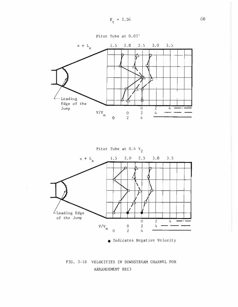
x + L x
-- )
Le ading Edge of the Jump
x + L x
Ft
= 2.56
Pit ot Tube at 0.03'
1. 5 2. 0 2 . 5 3.0 3.5
v/V m o
......... j'--,
I / ,/1
o 2
p
.1,
k [;,
V-~
o 2 4
.P
2 4
4
Pitot Tube at 0.4 Y2
1.5 2.0 2. 5 3.0 3.5
I
I
-/ /" r'
'/ L, \
""'-" \ l\
- Ii
Leading Edge of th e Jump
v/v
V m 0
I IJr
o 2
/ )
{ o 2 4
If
2 4 _.-4 ----
• Indicates Negative Ve loc i ty
FIG. 3-18 VELOCITIES IN DOWNSTREAM CHANNEL FOR
ARRANGEMENT REC3
60

--
-
-
F ~ 1. 86 t
Pitot Tube at 0.03'
x + L x 1.5
Leading Edge of the Jump
v/v m o
2.0
o 2
1/"
\ \
2.5
/
~
"\ o 2 4
~
/
l~' .L..>
Pitot Tube at 0.4 YZ
x + L 1 5 2 0 2 5 x
/' ",/ "--'
""" ./ ./ /
\ L ........
3.0
V
i'..
2 4 C
3 0
/
"'" -\.. "' r, ....... '" h
Leading Edge of the Jump
v/V m 0
o z
o 2 4
Z 4 6
3.5
3 5
4 _._
• Indicates Negative Velocity
FIG. 3-19 VELOCITIES IN DOWNSTREAM CHANNEL FOR
ARRANGEMENT REC 3
61

2.56
Pitot Tub e a t 0.03 '
x + L 1 5
-~ -
Lead ing Ed e of g Jump
t he V/ V
m o
2 0
....
......:. ., \
o 2
-
Pitot Tu be a t 0.4 Y2
x + L
-~ -
Lead ing Edge o f t he J ump V/ V
1.5
"
)
m 0
2. 0
\
/
o 2
L
~
2 5
r
~
?
1 '" .:r
/ o 2 4
2. 5
'\,
/1
~ P
o 2 4
j
3 0
\ ;1
2 4 , o
3.0
\,
11/
2 4
3 5
3.5
FIG. 3- 20 VELOCITIES IN DOWNSTREAM CHANNEL FOR
ARRANGEMENT REC3
6 2

x +
Leading Edge of the Jump
v/ v
x + L x
Lead ing Edge o f the Jump
v/v m
Pitot Tube at 0.03 '
1.5 2.0 2.5
o 2 4 _ . -
m o 2 4 6 - __ _
2 4 6 8 o
Pit ot Tube at 0.4 Y2
1.5
o
2.0
o 2 4
\
2 6
2. 5
o 4 8
2 6
4 -'-
FIG . 3- 21 VELOCITIES IN DOWNSTREAM CHPu~NEL FOR
ARRANGEMENT REC4
63

Leading Edge of the Jump
Leading, Edge of the Jump
x + L x
v/V
x + L x
v/V m
2. 56
Pitot Tube at 0 .03'
1.5
m
o 1
2.0 2.5
o 1 2 _ . o 1 2 3 ---2 3 4 5
Pitot Tube at 0.4 Y2
1.5
o 1
2.0
o 2
2.5
o 1 2 3
1 2 _ ._ J __ _
FIG. 3-22 VELOCITIES IN DOWNSTREAM CHANNEL FOR
ARRANGEMENT REC4
64

Leading Edge of the Jump
Le ad ing Edge of ehe Jump
F e 1. 12
Pieoe Tube at 0.03'
v / v m
1.5
o
2.0
o 2 24 6
Picot Tube at 0.4 Y2
v /v m
1.5
o 2
2.0
o 2 4 6
2.5
o 2 4 6 8
2.5
o 2 4 6 8
3.0
4 -·-8 --
3.0
4 - · -8 --
• Indicates Negative velocity
FIG. 3-23 VELOCITIES IN DOWNSTREAM CHANNEL FOR
ARRANGEMENT REC4
6s
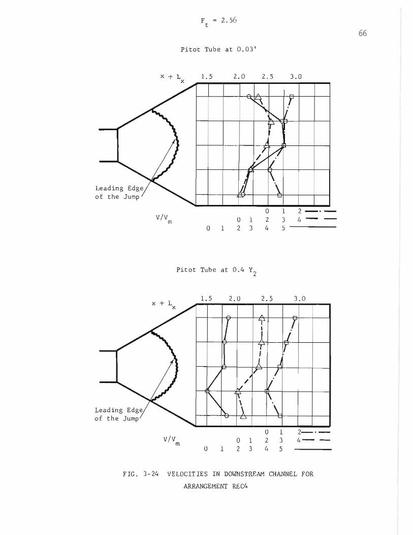
x +
v/v m
v/v
Pitat Tube at 0.03 '
1.5
o 1
2. 0 2.5
o 012 234
Pi t a t Tub e at 0.4 Y2
1. 5
m o 1
2.0
o 1 2 3
2.5
o 1 2 3 4 5
1
3.0
2 -·-
3.0
2-·-4--
FIG. 3- 24 VELOCITIES IN DOWNSTREAM CHANNEL FOR
ARRANGEMENT REC4
66

67
It was expected that the centerline velocities would be consider-
ably higher than the velocities measured near the sides of the channel.
However, this general expected pattern was violated in arrangement REC 2
as shown in Figures 3-13 to 3-16. These figures indicated that the
velocity ratios, V/V , along the centerline were Im,,-rer than those near the m
sides of the channel. The general velocity pattern for arrangement REC 1
was similar to REC 2. This type of velocity variation indicated that when
the flaring angle in the stilling basin was reduced to small magnitudes the
velocity ratios (V/V ) increased from the centerline of the channel toward m
the sides at any transverse section. The deviation from the expected
velocity pattern in arrangements REC 1, and REC 2 could be attributed to
the insufficient divergence of the flared wingwalls which did not allow full
development of radial flow. It was, furthermore, possible that the velo-
cities in the vicinity of centerline of the channel where the measurements
were taken had still been under the influence of jump turbulence and radial
flow characteristics, while near the sides velocities were resulted from
purely parallel flows.
In view of the above discussion, arrangements REC 1, and REC 2
were not suitable basins as far as velocity reduction was concerned. The
best structures were arrangements REC 4 followed by REC 3 for redUCing the
velocity and yet maintaining a fairly uniform velocity distribution in the
downstream channel.
The magnitude of V/V was generally decreased as the position of m
the jump was moved downstream. However, the decrease in V/V was not an m
indication of lower velocity (V) for more downstream position of the jump.

68
The velocities for the downstream jump positions were significantly higher
than velocities for the upstream jump positions. This variation in velo-
city was not indicated by V/V because the value of V increased at a m m
faster rate than the value of V as the jump position moved downstream.
The statement that the velocity increased as the jump moved downstream was
confirmed by the magnitudes of the evaluated velocities complied in test
data.
The symmetry of the velocity distribution about the centerline was
substantially disturbed in some test runs. The distribution of velocity
was skewed to one side of the channel. This skewness could be due to small
deviations in the symmetry of channel geometry, or the nonprismatic nature
of channel cross section. Arrangement REC 4 performed with very little
skewness of velocity distribution profile. Small values of flaring angle
could also contribute to the shifting of velocity distribution profile.
The effect of Ft
on the downstream velocity was such that, within
the range of experimentation, an increase in Ft
caused an increase in the
ratio of V/V provided that the channel geometry and the position of the m
jump were llnchanged.
Water Surface Profile: The degree of angular uniformity of flow
was estimated from the water surface profile within the basin when tail-
water conditions were such that no hydraulic jump was formed in the basin.
In order to determine the degree of the angular uniformity, the flow
profile measurements were made along radial distances in each arrangement.
The radial lines, along which the flow depth measurements were obtained,
o 0 0 0 0 were set at 5 , and 10 for arrangement REC 1; 5 , 10 , and 15 for REC 2;
o 0 0 0 0 15 , and 22.5 for REC J; 10 , 20 , and 30 for REC 4. The

69
channel centerline was used as the reference for setting off the radial
lines. Flow profile measurements were also taken along the centerline for
all arrangements.
Several representative water surface profiles are shown in Figures
3-25 through 3-28. These figures indicate the surface profiles for all
arrangements operating at Ft
of 2.56. The study of these figures revealed
that normally, at any given section, the flow depth on the centerline was
slightly higher than the intermediate lines. Furthermore, the depth of
flow decreased as the flow advanced downstream which was the characteristic
of radial flow basin. A relatively high flow depth was observed adjacent
to the flaring wingwalls, especially in the beginning portion of the basin.
The existence of this high flow depth could be attributed to an intense
pressure build-up in radial direction and the wall effect when the flow
entered the basin from the entrance channel. This high pressure diminished
as the flow advanced dOw~stream and a rapid decrease in the depth of flow
at the sides of the basin subsequently resulted.
Minor deviations in the uniformity of flow depth was observed in
all transverse sections within the stilling basin. The nonuniformity of
flow depth was mainly due to the upstream disturbance and the sudden
expansion of the circular conduit to rectangular channel. Other factors
such as boundary effects and the pressure distribution of flow within the
basin also contributed to the slight nonuniformity of water depth within
the basin.
Generally speaking, the radial flow basin maintained a fairly uni
form spreading of the flow except for a high wave formation near the
upstream portion of the flaring wingwalls. Comparison of Figures 3-25 to

w
""' E 0 w w 0
PO
C .... '" '" '" <l! > 0
.D < ~ 0
"' "" ""' 0
.c w P-<l!
Q
70
0.4
0.2
o
0.4
0.2
o-~~ 0 0-4)
4) 0
0
Ft
2.56
0.4
100 R
0.2
O~ ________ ~ ______ ~~~ __ ~ __ ~~ ______ ~ 1.0 1.5 2.0 2.5 3.0
x, oft.
FIG. 3-25 WATER SURFACE PROFILES OF FLOW FOR
ARRANGEMENT RECl

0.4
0.2
o
. .... 4-l
s 0.4 a .... .... a
J:Q
c: -rl tI')
CIj J:Q
(l) 0.2 ? a
..Cl <: ) a ,..., ~
4-l 0 a ..c::: ....
0.4
0.2
o
0 0- ~~ ~ -0-
Ft = 2.56
o--._..l..t:"_
1.0 1.5 2.0 2.5
X, ft.
FIG. 3-26 WATER SURFACE PROFILES OF FLOW FOR
ARRANGEMENT REC2
71
0
3.0

0.4
0.2
o
~
E 3 0.4 .w o 1'0
c: 'M [fJ
ell 1'0
~ 0.2 o ~
o
0.4
0.2
o 1.0
~0~150L 4-. --0-' ::z::.~. ~.~::t=.-:::::g
0---
-----0---
Ft
= 2.56
1.5 2.0 2.5
x, ft.
FIG. 3-27 WATER SURFACE PROFILE OF FLOW FOR
ARRANGEMENT REC3
-0
72
3.0

. .u 4-l
~
6 0 .u .u 0
t:C1
t::: -,..; til co
t:C1
0)
:> 0
~ ~ 0
...-l
"'" 4-l 0
..c: .u P-O) Q
73
0.4
0.2
o ~----------------------------------------~
0.4
0.2 <t 0 0- -0-
~ 0
0
Ft
= 2.56
0.4
30° R
0.2
o ~--------~--------~----------~--------~ 1.0 1.5 2.0 2.5
x, ft.
FIG. 3-28 WATER SURFACE PROFILES OF FLOW FOR
ARRANGEMENT REC4
3.0

74
3-28 indicated that the best spreading action with continuous decrease in
the flow depth along the radial lines, the best symmetry of flow profile
about the centerline, and the smallest depth of waves adjacent to the
flaring side walls were provided by arrangement REC 2.
II - Trapezoidal Downstream Channel
Since many natural as well as artificial channels, in the interest
of economy and bank stability, are trapezoidal, a study of flow perfor
mance of this type of downstream channel with a connection to a radial
flow basin was needed. For this reason five different geometric arrange
ments were tested during this experimental study. The most difficulty in
the selection of proper geometric dimensions was encountered in the design
of a workable transition from the stilling basin to the trapezoidal down
stream channel. A systematic method for estimating the general perfor
mance of any transition design in this case was not available prior to this
experimental work. Therefore, several design configurations were
considered and analyzed. The analysis was primarily based on construction
possibilities and economical considerations. The principal interest in
this study was centered around the trapezoidal downstream channel having
2:1 side slopes. The length of the basin along the centerline as well as
the flaring angles of the wingwalls were fixed at 26 inches and 300
respectively in all arrangements.
Hydraulic performance of three structural configurations were of
interest. These three structures had Bib ratios of 1, 2, and 2 corres
ponding to Z values of 6, 6, and 18 inches respectively. After choosing
Bib and Z values, the variable dimensions such as the base length of the

triangular converging walls and the height of the abrupt rise at the end
of the stilling basin were adjusted for the best basin performance.
75
The first visual observation was made on the hydraulic performance
of an arrangement without any abrupt rise. The performance of this basin
was extremely unsatisfactory. The flow of water with high kinetic energy
entered the basin and advanced downstream until it came into contact with
the converging walls. A considerable turbulence accompanied by shooting
of water in the air was created as the result of the contraction of the
converging walls in the direction of flow. This undesirable feature could
only be eliminated by a tailwater control. The tailwater depth had to be
high enough to ensure the formation of a hydraulic jump within the stilling
basin. However, in actual field situations the required tailwater depth
could not always be maintained. Since this type of arrangement exhibited
a high scour potential with relatively low energy dissipation its practi
cality for the purpose of this investigation was ruled out.
In order to eliminate the aforementioned undesirable characteristic,
it was decided to incorporate an abrupt rise at the end of the basin.
Several different sill heights were experimentally investigated. On the
basis of satisfactory performance, sill heights of 0.75 inch and 1.5 inches
were selected for arrangements with Z values of 6 and 18 inches respectively.
The abrupt rise at the end of the basin along with the contraction effects
of the converging walls forced the formation of the hydraulic jump within
the basin independent of the tailwater depth. This was especially
advantageous since the tailwater could not be controlled always to a
desirable depth under field conditions.

76
The effect of the magnitude of c/b in water surface profil~s of the
two structures showed that the hydraulic performance of the basin was not
too sensitive to changes in c/b within the range of experimentation. c was
the base length of the triangular converging walls. Based on the low
sensitivity to c/b and construction advantages, specific values of c/b
were selected for each arrangement.
Three arrangements were considered practical for actual construc
tion purposes and satisfactory hydraulic performance. TRAP 1 was undesir
able because the end sill was too high and would require unnecessary exca
vation for the apron. TRAP 3 was undesirable because c was too large
giving a flatter slope to the triangular transition surface and causing
the flow to climb higher on the outside walls. The satisfactory arrange
ments were TRAP 2, 4, and 5 shown in Table 1. The c/b ratios for these
arrangements were 2.5, 1.80, and 2.25 respectively. A detailed study of
the performance of these three arrangements follows. In the study of the
performance of the trapezoidal downstream basin, the jump stability, the
degree of velocity reduction of flow passing through the basin, and the
shape of the water surface profile were of interest.
Stability of the Hydraulic Jump: So far as the jump stability was
concerned, arrangements TRAP 2, 4, and 5 performed with satisfactory
results. The hydraulic jump was formed in each arrangement independent
of tailwater requirements within the allowable range of Ft' Figures 3-29,
30, and 31 show the locations of the jump when Y2 was larger than or equal
to the tailwater depth. It should be noted that for different values of
Ft
in all arrangements the leading edge of the jump was positioned within
the upper section of the stilling basin. Any tailwater depth lower than
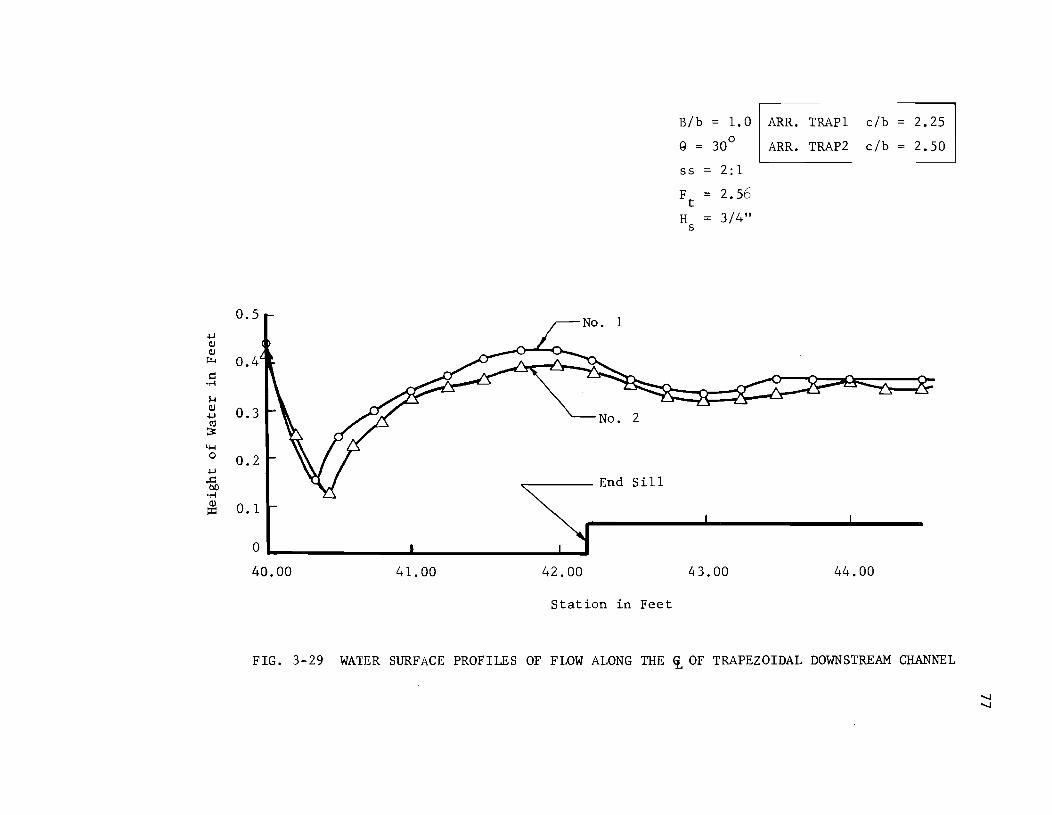
B/b = 1.0 ARR. TRAP1 c/b 2.25
9 = 30° ARR. TRAP2 c/b 2.50
88 2:1
Ft
2.56
H 3/4" 8
0.5 .j..J Q) Q) ~ 0.4 r:: .~
H Q) 0.3 .j..J C1j No. 2 ~
4-l 0 0.2
.j..J
..c: 00 ~--- End Sill .~
Q) o. 1 ::t::
0
40.00 41.00 42.00 ~3.00 44.00
Station in Feet
FIG. 3-29 WATER SURFACE PROFILES OF FLOW ALONG THE i OF TRAPEZOIDAL DOWNSTREAM CHANNEL

.!..I Q) Q)
t:t..
~ 'r-!
J.j Q)
.!..I t'i! :3 ll-I
° .!..I ..r::: co
'r-! Q)
::I:
0.5
0.2
End Sill
0.1
0 40.00 41.00 42.00
Station in Feet
43.00
Bib = 2
g = 30°
88 = 2:1
clb = 1. 8
H '" 3/4" 8
Z = 6/1
ARRANGEMENT TRAP 4
44.00
FIG. 3-30 WATER SURFACE PROFILES OF FLOW ALONG THE ~ OF TRAPEZOIDAL DOWNSTREAM CHANNEL

~ OJ OJ
""" ~ .~
1-4 OJ ~ (\:I
;3::
4-l 0
~
.c: 00 .~
w ::t:
0.4
0.3
0.2
0.1
0 40.00 41.00
B b = 2
g = 30°
55 = 2:1
H = 1±-" 5 2
Z = 18"
ARRANGEMENT TRAP 5
42.00 43.00
Station in Feet
44.00
FIG. 3-31 WATER SURFACE PROFILE OF FLOW ALONG THE ~OF TRAPEZOIDAL DOWNSTREAM CHANNEL

80
Y2 did not affect the position of the jump. When the tailwater depth
became lower than Y2' supercritical flow in the downstream channel
resulted with a Froude number close to unity. However, since the down-
stream Froude number was close to unity,there would be no danger of scour-
ing damage in the immediate vicinity of the basin within the downstream
channel. When the tailwater depth was increased to a value greater than
Y2' the jump was moved upstream and finally became submerged.
In the discussion of the stability of the hydraulic jump for a
rectangular downstream channel the effectiveness of the radial flow basin
was pointed out. This effectiveness was especially apparent in TRAP
arrangements when the jump was formed within the radial flow basin. Since
in arrangements TRAP 2, 4, and 5 it was impossible for the jump to leave
the basin and move into the downstream channel, the stabilizing effects of
the radial flow basin were always present. The effect of Ft
on the posi
tion of the hydraulic jump is shown in Figure 3-30. The water surface pro-
files indicating the jump positions for Ft
of 1.86 and 2.56 in arrangement
TRAP 4 are shown in this figure. The jump position for Ft
of 2.56 was
more upstream than that of F equal to 1.86. This indicated that as F t t
decreased from its limiting value, the jump position moved downstream
within the basin. The limiting value of Ft
was previously defined as the
Froude number at which the free fall flow would take place.
Comparison of Figures 3-30 and 3-31 showed that an increase in the
height of drop of entrance channel (2) placed the leading edge of the jump
farther upstream in the basin. This behavior was attributed to the fact
that when Ft
was constant, an increase in 2 increased the Froude number at

81
the beginning of the flared wingwalls because of the increased kinetic
energy at this section.
Another factor in locating the position of the jump was the com-
bined contraction influence of the converging walls and the abrupt rise in
the flow. Contraction influence was defined as the ability of flow to be
converged when the fluid advanced through the transition zone in the basin.
The contraction influence was a function of Bib, clb, ss, Q, and H. An s
increase in the contraction influence moved the jump upstream. This
effect is observed in the position of the jump in Figures 3-29 and 3-30.
The effect of Bib on the jump position was hence apparent from its effect
on contraction influence. The smaller the ratio of Bib, the higher the
contraction influence, thus the more upstream the jump position. For this
reason the jump position was more upstream in arrangement TRAP 2 than
arrangement TRAP 4 for the same Ft as indicated in Figures 3-29 and 3-30.
Velocity Distribution and Reduction: Velocity measurements were
obtained at 0.03 foot, 0.4Y3' and 0.8Y3 from the channel bottom in trape-
zoidal channel. It is noteworthy that the depth Y3 was not necessarily
the same as the sequent depth, Y2' of the hydraulic jump. The procedure
followed in obtaining the velocity measurements was essentially the same
as the procedure used for the rectangular channel section. All velocity
measurements were made under the condition of no tailwater control. Three
transverse sections were considered for velocity measurements. These
sections were located at 2.0, 3.0, and 4.0 feet, along the centerline of
the channel, from the beginning of the flared wingwalls. The relative
velocity magnitudes of vlv in these sections are shown in Figures 3-32 m
through 3-36. Velocity measurements were obtained for Ft of 1.86 and 2.56

B/b
Q
ss
H s c/b
Z
1. 86
Pitot Tube at 0.03'
Leading Edge of the Jump----__ ~
1
30°
2: 1
= 3/4"
2.5
= 6" x +
Leading Edge of I the Jump
2.0
V/V m
0
Pitot Tube at 0.4 Y3
L 2.0 x
82
3.0 4.0
3-'-0 1 2 3 --
1 2 3
3.0 4.0
V/V m
o 1 2 3---0123--
o 1 2 3
FIG. 3-32 VELOCITIES IN DOWNSTREAM CHANNEL FOR
ARRANGEMENT TRAP2

B/b ==
9 ==
ss
H S
c/b
Z ""
Leading Edge of the Jump
1
30°
2:1
3/4 11
2.5
6"
2.56
Pitot Tube at 0.03'
x + L x
V/V m
Pitot Tube
x+
2.0
0
at 0.4 Y3
2.0
83
3.0 4.0
0 1 2 3-,-0 1 2 3 --
1 2 3
3,0 4.0
o 1 2 3 _._ o 1 2 3--
o 1 2 3
FIG. 3-33 VELOCITIES IN DOWNSTREAM CHANNEL FOR
ARRANGEMENT TRAP2

Bib 2
9 30°
S8 2: 1
H 3/4" S
c/b 1.80
Z = 6"
Pitot Tube at 0.03'
2.0
v/v m
0 1
Pitot Tube at 0.4 Y3
x + L 2.0 x
v/v m
o 1
2
2
3.0
0 3
3.0
o
1
1
4.0
2
4.0
o 2 3
3---
FIG. 3-34 VELOCITIES IN DOWNSTREAM CHANNEL FOR
ARRANGEMENT TRAP4
84
1 3 _.---
1 2 3 _.-

B/b
9
S8
c/b
Z
2
Leading Edge of the Jump'
300
2: 1
3/4"
1.80 II
F = 2.56 t
Pitot Tube at 0.03'
2.0
V/V m
0
Pitot Tube at 0.4 Y3
x + 2.0
1
85
3.0 4.0
0 1 2 3-·-
0 1 2 3 --2 3
J.O 4.0
o 1 2 3 _.-V/V
m o 3
1 2 3 o 1 2
FIG. 3-35 VELOCITIES IN DOWNSTREAM CHANNEL FOR
ARRANGEMENT TRAP4

Bib 2
Q 30°
ss 2:1
H 1.5" s
clb 2.25
Z 18 ft
Pitot Tube at 0.03 1
2.0 3.0
v/V 0 1 2 m 0 1 2 3
Pitot Tube at 0.4 Y3
x + L 2.0 3.0 x
v/v m o 1 2
o 1 2 3
4.0
0 3
4.0
FIG. 3-36 VELOCITIES IN DOWNSTREAM CHANNEL FOR
ARRANGEMENT TRAP5
86
1 2 3-'---
3-'-

87
in arrangements TRAP 2 and 4. In arrangement TRAP 5 the velocities were
obtained only for Ft of 1.86 since Ft
of 2.56 was out of the range of
experimental validity. The uniformity of the velocity distribution in the
downstream channel could be observed in Figures 3-32 to 3-36. Several
interesting features of these figures are noteworthy. The velocity ratio
V/V was fairly uniform in any transverse section for given hydraulic and m
geometric conditions. The velocity distributions for a given flow condi-
tion in the three transverse sections of the downstream channel were similar
to each other. Furthermore, the velocity pattern and magnitude was almost
the same for experimental results obtained at 0.03 ft., 0.4Y3' and 0.8Y3'
This was an indication of the velocity uniformity in transverse, longitu-
dinal, and vertical directions.
The effect of Ft
on the velocity magnitude was rather small,
especially in arrangement TRAP 2. When Ft
was changed from 1.86 to 2.56,
a noticable velocity variation could not be detected in this arrangement.
In arrangement TRAP 4, an increase in Ft
decreased the magnitude of V/Vm
slightly. This, of course, was due to the combined effect of the changes
in V as well as Vm when Ft
was varied. The effect of F on V/V in trape-t m
zoidal channel was opposite to that indicated by the performance of the
rectangular downstream channel. In the rectangular downstream channel, an
increase in Ft
increased V/Vm
' Comparison of Figures 3-34 to 3-36 showed
a close agreement in the velocity distributions and magnitudes of V/V m
between arrangements TRAP 4 and 5. This agreement became more pronounced
as the flow advanced downstream.
A relatively high degree of velocity reduction was observed in all
experiments. The downstream channel velocities varied within a small range

in all geometric configurations. However, the velocities upstream from
the jump varied considerably from arrangements TRAP 2 and 4 to arrange
ment TRAP 5 for the same Ft' The velocity upstream from the jump was
much higher in arrangement TRAP 5 than that of TRAP 2 and 4. Hence the
best velocity reduction was observed in arrangement TRAP 5.
The velocity distribution and uniformity of arrangements TRAP 2,
88
4, and 5 indicated a satisfactory performance on each of these three basins.
Depending on the availability of geometric dimensions either one of these
basins could be used efficiently.
Water Surface Profile: The general appearance of water surface
profile along the channel centerline for arrangements TRAP 2, 4, and 5 are
shown in Figures 3-29, 3-30, and 3-31 respectively. The hydraulic jump was
followed by a critical section created over the crest of the abrupt rise.
Under the condition of no tailwater control, the depth of flow in the
downstream channel was close to the critical depth. The critical depth
represents the state of flow at which the specific energy is minimum for a
given discharge. Since a supercritical flow could not occur immediately
downstream from the dissipating structure, a severe scour and erosion
potential would not be anticipated.
The effect of Ft
on the water surface profile is shown in Figure
3-30. An increase in Ft caused a decrease in the depth of water. Of
course, this type of variation is apparent from the energy relationships
within the flow median. The water surface profile was rather uniform in
all experiments.
The purpose of this type of stilling basin was to allow the uniform
spreading of water before the jump occurs. Hence, the length of the basin

89
had to be such that the water spread uniformly upstream from the jump. The
closer the leading edge of the jump to the vertical face of the abrupt rise,
the more efficient the performance of the basin. The situation would also
allow satisfactory performance of the basin when the tailwater depth was
higher than the sequent depth Y2. Of course, the economic consideration
was also a controlling factor in selecting the length of the basin. No
attempt was made in this investigative work to test the effect of the
basin length in the hydraulic performance of the structure. However, it is
anticipated that the longest possible length within the region of wingwalls
would have the best performance. The reason being the full development of
radial flow within the region of flared wingwalls.
The depth of water in the trapezoidal section, when Ft
equaled 2.56,
was highest in arrangement TRAP 2 and lowest in arrangement TRAP 5. Accord
ing to the results obtained and analyzed in this report, the general per
formance of the trapezoidal basin was preferred to that of a rectangular
downstream channel basin. This evaluation was based on the tailwater
requirements, the velocity reduction, and the jump stability. Besides these
advantages, the trapezoidal downstream channel basin could be effectively
operated on a larger range of discharges. The basin for trapezoidal down
stream channel is self cleaning and there would be no danger of debris
accumulation within it. The high turbulence within the basin carries any
debris or sediment material into the downstream channel.
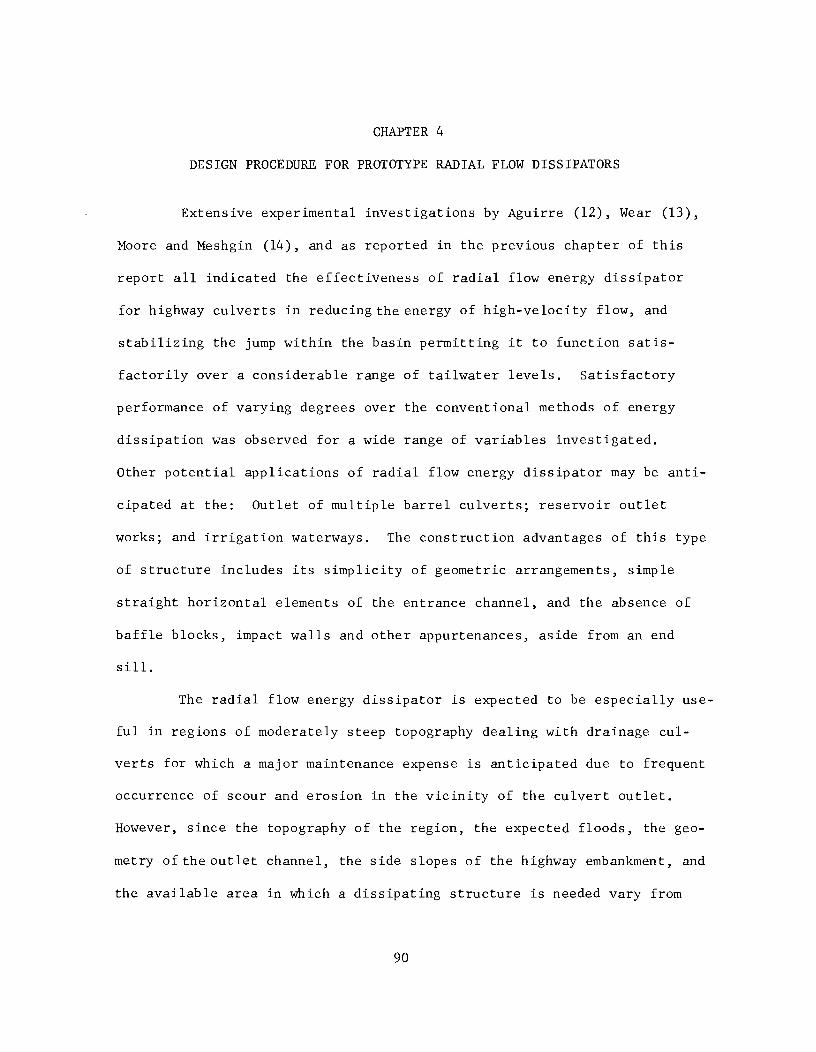
CHAPTER 4
DESIGN PROCEDURE FOR PROTOTYPE RADIAL FLOW DISSIPATORS
Extensive experimental investigations by Aguirre (12), Wear (13),
Moore and Meshgin (14), and as reported in the previous chapter of this
report all indicated the effectiveness of radial flow energy dissipator
for highway culverts in reducing the energy of high-velocity flow, and
stabilizing the jump within the basin permitting it to function satis
factorily over a considerable range of tailwater levels. Satisfactory
performance of varying degrees over the conventional methods of energy
dissipation was observed for a wide range of variables investigated.
Other potential applications of radial flow energy dissipator may be anti
cipated at the: Outlet of multiple barrel culverts; reservoir outlet
works; and irrigation waterways. The construction advantages of this type
of structure includes its simplicity of geometric arrangements, simple
straight horizontal elements of the entrance channel, and the absence of
baffle blocks, impact walls and other appurtenances, aside from an end
sill.
The radial flow energy dissipator is expected to be especially use
ful in regions of moderately steep topography dealing with drainage cul
verts for which a major maintenance expense is anticipated due to frequent
occurrence of scour and erosion in the vicinity of the culvert outlet.
However, since the topography of the region, the expected floods, the geo
metry of the outlet channel, the side slopes of the highway embankment, and
the available area in which a dissipating structure is needed vary from
90

91
one situation to another, a standardized design of radial flow energy
dissipator may not be advisable. For this reason and based on experimental
and analytical results a procedure is recommended in this chapter which
helps the engineer in designing an effective radial flow energy dissipator
under given set of field conditions.
When the existing field conditions, expected drainage, and the
highway dimensions are kno,Yn, and scour or erosion is anticipated, the
engineer is faced with the selection of a proper culvert size and its
slope, required height, width, and the radius of curvature of entrance
channel, the angle and the height of the flaring wingwalls, the length of
the basin, and a workable Bib ratio. Upon choosing the aforementioned
dimensions a suitable transition from the stilling basin to the downstream
channel such as an end sill for rectangular downstream channel and the
triangular converging walls incorporating an end sill for trapezoidal
downstream channel may be recommended to improve the performance of the
basin and to make the proper connection between the stilling basin and the
downstream section. In the following articles a systematic approach to the
selection of these dimensional variables is discussed and analyzed.
Hydraulic Design of Culverts
The hydraulic of conventional culverts are thoroughly discussed in
many hydraulic structure books and publications which include charts for
selecting a culvert size at a given set of conditions. No attempt is made
to cover all phases of culvert design in this section and the designer is
referred to Chow (16) for detailed procedure in design of highway culverts.
Since the inlet flow line elevation is fixed, the outlet flow line elevation

92
must be selected in such a manner that sufficient height of drop is
provided. Any outlet flow line elevation above the minimum required
elevation governed by the drop height is permissible provided that it is
economically feasible. After choosing the culvert outlet flow line eleva
tion for a given highway cross section, the slope and the required size
of the culvert may be determined. Two types of slope, namely mild or
steep, may result. If the selected slope of the culvert is mild, critical
depth of flow may be assumed to exist at the outlet of the culvert. How
ever, if the slope is steep and the culvert is long, a normal depth may be
used as the depth of flow at the outlet of the culvert. For short culverts
and steep slopes, one of the conventional methods of water surface profile
determination must be followed to estimate the expected depth of flow at
the top of the vertical drop.
Width, Height, and the Radius of Curvature of Entrance Channel
The selection of the size of the culvert would determine the width
of the entrance channel. This width must be the same as the width of the
box culvert or the diameter of the circular culvert used under the highway.
If the circular culvert is recommended, then, the connection between the
culvert and the entrance channel should be an abrupt expansion. The
entrance channel must have a rectangular cross section at every transverse
section having a height of side walls at least equal to the depth of flow
plus an appropriate freeboard. The height of the side walls must also be
such that the vertical distance from the surface of the embankment on the
side slopes of the road to the top elevation of the side walls at any
section does not exceed two feet. This is a general recommended limit by

93
Highway Departments and exceptions in exceeding this limit are permissible
where existing conditions indicate another acceptable solution; however,
any such exceptions should be based on the results of thorough engineering
study. Figure 4-1 shows a typical culvert installation and the radial flow
energy dissipating structure.
In choosing the height of drop of the entrance channel several fac
tors are of primary importance. Some of these factors are: the shortest
horizontal distance from the beginning of the entrance channel to the
centerline of the highway; the extent that the highway fill can be excavated
for placing the dissipating structure; the available distance from the
highway centerline to the highway right-of-way line; and finally the outlet
flow line elevation of the culvert and the elevation of the bottom of the
basin. Furthermore, the height of drop should be sufficient to cause
enough pressure build-up in the flow as it impinges on the stilling basin
floor to cause the desired lateral spreading of the flow. Based on experi
mental results, a minimum height of one times the culvert width or diameter
is recommended as the lower limit of drop height. The process of selecting
a feasible drop height calls for a trial solution of the problem. Based on
the given conditions, several drop heights must be chosen and examined at
first to determine their economic and hydraulic feasibility. After com
paring several workable solutions, the most advantageous one may be adpated.
Since a wide range of the values of drop height could be used in this type
of structure and still result in an effective energy dissipator, the
choice of a suitable height can be determined by engineering judgment and
economical considerations.

Highway <t
\
Inlet Outlet
z
Stilling Basin
Max. 2'
Top jI'----- Wingwa 11s
Downstream Channel
FIG. 4-1 SCHEMATIC REPRESENTATION OF CULVERT INSTALLATION AND DISSIPATING STRUCTURE
R.O.W.

95
In design of a workable entrance channel the proper selection of
the radius of vertical curvature for the drop is of primary importance.
Too small a radius of curvature may cause excessive negative pressure on
the bottom of the entrance channel or separation of the flow from the
lower boundary, thus impairing the operation of the stilling basin. By
limiting the negative pressure head to a minimum of approximately -1.5Yt'
Aguirre (12) recommended a mathematical relationship shown in equation
(4.1) for determination of the radius of curvature R of the vertical drop.
R
y F2 t t
2.5 (4.1)
He assumed that the top of the vertical drop is the critical section so far
as negative pressure is concerned. Upon this basis, Aguirre recommended
a radius of curvature for the model operating at a specific Froude number
(F t ). However, the experimental results discussed in the previous
chapter indicated that the circular culvert model could not be operated at
this design Ft. At design Ft
the free fall, or separation, of flow
occurred and as indicated before,the limiting Froude number (Ft
) was some-
what less than the design value. Application of equation (4.1) would
result in the computation of a radius of curvature which is insufficient
for proper hydraulic performance of the entrance channel. Because of the
aforementioned reasons a curvature design procedure is recommended
assuming that the critical section for the occurrence of maximum negative
pressure is the lower portion of the vertical curve. It should be noted
that these pressures cannot be accurately calculated by elementary means,
but if the assumption of a free, or irrotional vortex is made a functional
relationship may be obtained suggesting an approach to the evaluation of

96
pressure head on the curved channel bottom. This assumption is a reason-
able one, since losses must be small over the short length of entrance
channel, and the turbulent approaching flow usually has a uniform trans-
verse velocity distribution which is the characteristic of irrotational
flow. Considering the above assumptions, the derivation of the functional
relationship expressing the pressure on the channel bottom (P2) of the
entrance channel is as follows: The simplified Euler's equation in polar
coordinates applied to any element of fluid streamline may be represented
by:
dh dr
a r
g (4.2)
where r is the radius of curvature of the element of streamline, h is the
piezometric head at r, a is the normal component of acceleration directed r
toward the center of curvature, and V is the mean velocity of flow. Inte-
grating equation (4.2) between points I and 2 shown in Figure 4-2 the
following would result:
or
2 JR+y'L dr
R rg
V2
L (R + Y) og R g e
(4.3)
(4.4 )
where R is the radius of curvature of entrance channel, and Y is the depth
of flow on the entrance channel. Since,
(4.5)
where z is the elevation of the point in question with respect to a
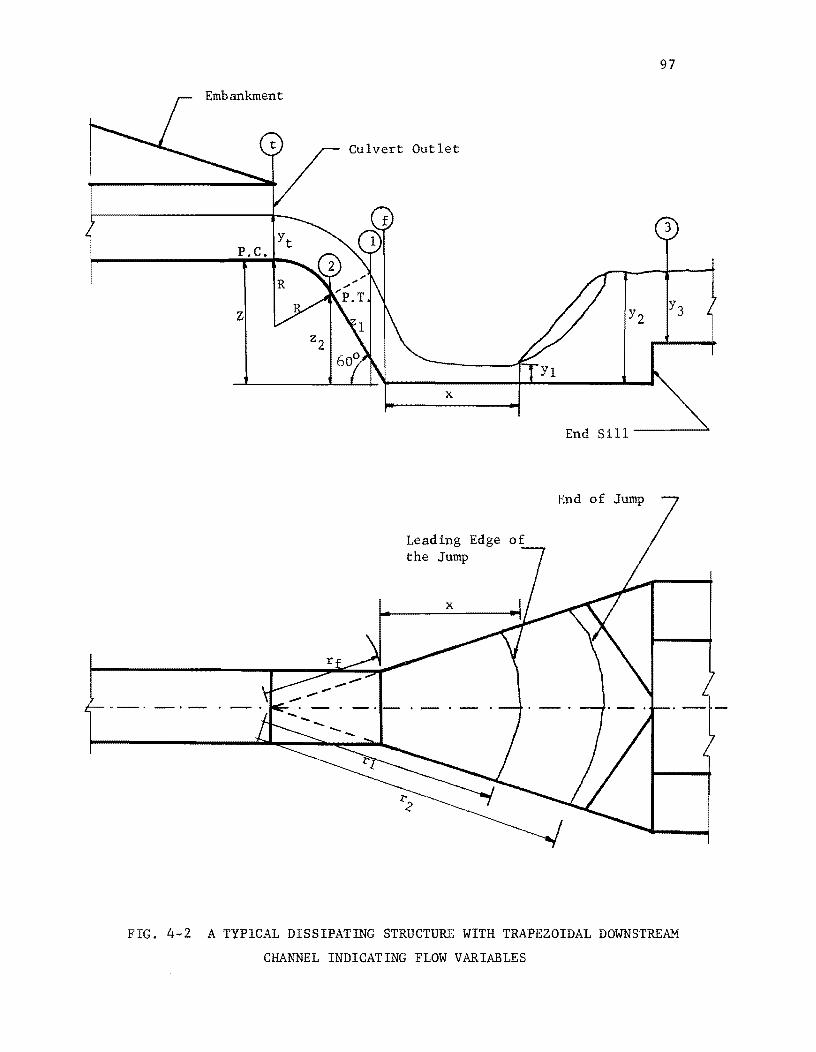
Embankment
P.C.
z
Culvert Outlet
x
Leading Edge the Jump
x
97
3
Y2
End Sill-----"
End of Jump
FIG. 4-2 A TYPICAL DISSIPATING STRUCTURE WITH TRAPEZOIDAL DOWNSTREAM
CHANNEL INDICATING FLOW VARIABLES

98
reference plane, substitution of equation (4.5) into equation (4.4) gives,
PI P2 V2 R Y - + 2 - Log (-+-) y 1 Y - 22 = g e R (4.6)
where PI and P2 are pressures at points 1 and 2 respectively. Since the
pressure at point 1 is atmospheric, p/y can be dropped
(4.6). Substitution of (2 - 22
) = Y Cos 600
1: Y into 1 2
results in:
V2 Y P2
2 Y (R + Y)
Log R g e
or in dimensionless form:
Y/2 - P2/ Y
2 V /g
(R + Y) Loge R
The negative pressure head P2/ Y may be represented as:
P2
Y - c Y
from equation
equation (4.6)
(4.7)
(4.8)
(4.9)
where c is a constant. Substituting equation (4.9) into equation (4.8) it
becomes:
or
(0.5 + c)Y 2
V /g
0.5 + c
F2 pt
L (R + Y) oge R (4.10)
L (R + Y) oge R (4.11)
Where F is the Froude number at the point of tangency of entrance channel pt
and Fpt ~ Ft' Y = Yt' therefore:

99
0.5 + c 2
Log e
R + Yt ( R ) (4.12)
Ft
In order to estimate the approximate value of c, the limiting Froude num-
ber (Ft
) from Figure 3 - 7, the corresponding flow depth, and the magni-
tude of the radius of curvature of entrance channel in the model were
applied to equation (4.12). The value of c was hence determined to be
unity. Substitution of numerical value of c in equation (4.12) results
in: R + y
L ( t) oge R (4.13)
Since Ft
and Yt are known quantities, direct application of equation (4.13)
results in the evaluation of the radius of curvature R. Values of Ft
versus yt/R computed from equation (4.13) are plotted in Figure 4 - 3 for
a limited range of variables. Wherever applicable this graph may be used
instead of equation (4.13) to simplify mathematical computations.
Experimental results showed that the most effective geometric con-
figuration is the one in which the beginning of the vertical curve of the
entrance channel is located at exactly the end of the culvert under the
highway. Because of performance characteristics and ease of construction,
therefore, the point of curvature of entrance channel must be tied to the
outlet of the culvert. The vertical curve of the entrance channel must be
connected to the bottom of the stilling basin by a short straight section
which is tangent to the vertical curve and intersect the stilling basin
bottom at an angle of 600
• The 600
angle was used in all the model studies
and was chosen arbitrarily with consideration for the fact that it was
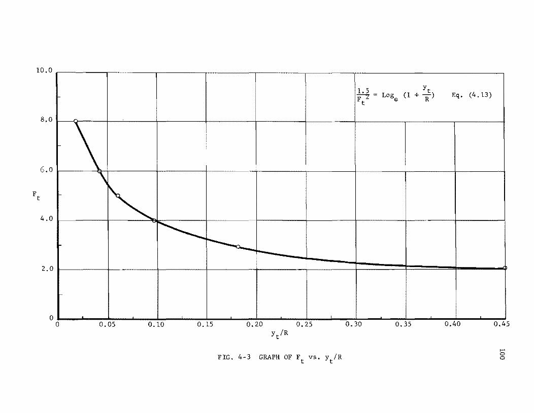
10.0
t-
8.0
6.0
\ -
~ 4.0
~ ~ -
2.0
-
o • o 0.05 0.10 0.15 0.20 0.25
FIG. 4-3 GRAPH OF Ft
VS. Yt/R
1.5 Log (1 -:;;;-'Z = F
t e
0.30 0.35
Yt + -) R
Eq. (4.13)
0.40 0.45
I-' o o

101
desirable to make the angle as large as possible to promote spreading
action and avoid construction problems.
Stilling Basin Dimensions
Since the model studied in this investigation made use of a circu-
lar hydraulic jump, a review of this type of jump and its potential appli-
cation is presented. The knowledge of functional relationships in this
type of jump is an essential feature of proper stilling basin design.
When supercritical flow spreads radially on a horizontal surface a circular
hydraulic jump may occur. The theoretical analysis of circular hydraulic
jump is based on the application of the continuity and momentum principles
applied to a sector of the jump. The component parts of the circular
jump along with the forces acting on a section of the jump confined by an
angle dQ are shown in Figure 2-1. The variables used in the derivation of
the sequent depth relationships are also shown in the same figure. The
assumptions made in the derivation of circular jump equation as outlined
in Chapter 2 are that: (1) the incompressible radial flow exists; (2) the
friction shear along all solid boundaries in the jump region is negligible;
(3) the energy and momentum coefficients are unity; (4) the hydrostatic
pressure distribution prevails before and after the jump; (5) and the
profile of the jump is a straight line. The derivation of the sequent
depth equation is as follows:
I PI 1= ~ 2
yYl rl
dQ (4.14 )
I P21 = 1:
2 r2
dQ 2 yY2

102
(4.15 )
where Pl
, P2
, P ,and P are forces acting on the surfaces shown in sl s2
Figure 2-1. Applying momentum principle,
Pl
- P2
+ 2Psl
Sin (~Q) (4.16)
For small angles, . dQ dQ
Sm (""2) = ""2.
Direct substitution of continuity equation into equation (4.16 ) and its
simplification results in:
2 r
2 y
(1.) r
2 [ 1 +
Y Y2 ] 2V
l r
l Yl 1 - - (-.1.) 2 + (- - 1) (-.1.)2 +- (r - 1) (4.17)
rl Yl 3 r
l Yl Yl gY l 2 Y2
Froude number upstream from the jump, and substituting them into equation
(4.17) results in:
ro - 1 2
2r + 1 Yo o
ro + 6F~ + 2
2r + 1 Yo + r o 0
(2r + 1) o
o (4.18)
It is desirable to obtain a simplified form of equation (4.18) so
that it can be more readily applied to design situations. A simplified
circular jump equation may be obtained by plotting numerous values of Yo
and Fl for different values of roo These values are determined for a
practical range of variables by a FORTRAN IV computer algorithm run on
CDc-6600 computer and plotted in Figure 4-4. The Newton-Raphson iterative
technique was the basis for this computer solution. Other information
concerning the computer program such as description of variables, flow
chart, and program write-up are shown in Appendix A. Several features of
Figure 4-4 are noteworthy and helpful in indicating that a simple

103
11.0
10.0
9.0
B.O
7.0
>: ~
>. 6.0 II
->;
5.0
4.0
3.0
2.0
3.0 5.0 7.0 9.0 11.0 13.0 15.0
FIG. 4·4. PLOT OF Yo VS. F1

104
relationship between y , r , and Fl exists for the range of variables of o 0
common interest. These features are that: (1) a linear functional rela-
tionship is present between Yo and Fl for a specified ro; (2) the curves
having r of 1.0 through 8.0 all intersect at a common point; and (3) the o
angle confined between any two consecutive r curves decreases in somewhat o
a uniform rate as r increases. Based on these indications, linear equao
tions of a straight line of the form:
(4.19)
where m is the slope of the curve and c is the intercept of y axis are o
fitted to the curves of Figure 4-4. It is fortuitous that the following
relationship holds true for the range of r under consideration: o
m + c 1.0 (4.20)
The reason for validity of equation (4.20) is that the point of intersec-
tion of all curves coincide with a point having Yo and Fl coordinates of
1, and 1. This condition, hence, suggests that:
or
1 - m (1 - F ) 1
(4.21)
(4.22)
Since the angle confined between any two consecutive r curves o
appears to change in a systematic manner, a relationship between rand m o
must exist. This relationship could be detected from the graph of m
versus r. Therefore, values of m as a function of r are plotted in a o 0

illS
Log - Log graph paper as shown in Figure 4-5. The equation of the curve
passing through the plotted points in Figure 4-5 is found to be:
m 1.54 -0.47
r o
(4.23)
Substitution of equation (4.23) into equation (4.22) results in the follow-
ing simplified version of equation (4.18).
-0.47 1 - 1.54 ro (1 - Fl ) (4.24)
The error resulting in computation of y from equation (4.24) was o
less than 3% of that computed from equation (4.18) for the range of var-
iables shown in Figure 4-4. This error is within the acceptable limits for
hydraulic jump computations.
Through the application of equations (2.6) and (4.24), proper
stilling basin dimensions such as the length, the flaring angle and the
height of the wingwalls are determined. The flaring angle of wingwalls
and the length of the basin are first selected in a trial process, with
some controlling factors. These factors are as follows: The flaring angle
9 must be within an effective range of 150
to 450
, which was determined
experimentally, and the maximum allowable length of the basin is fixed by
the geometry and properties of the area under consideration. With these
limitations in mind, an arbitrary length is selected. Since Band bare
known parameters, for a trial value of length, the angle 9 could be com-
puted from the geometry of the basin.
Upon selection of the first trial values of basin length (L) and
the flaring angle g, the values of Yf and Vf
must be computed. Yf and Vf

106
3.0
1.S4r -0.47 m =
0
2.0
.......
1.0 .-< 0.9 ~
UJ 0.8 :>
0 0.7 :>-<
~
0 0.6 <J.)
:> H ::i O.S
U
() ....
'~
" ~ "'-~l
"""< '\ "'< ~ ~ <J.)
..c .i-J
0.4 ~
0
<J.)
0.-0
.-< 0.3 CIl
~
E
0.2
0.1
1 2 3 4 S 6 7 8 9 10
r2 r =
0 r 1
FIG. 4-S GRAPH OF m vs. r 0

107
are the index depth and average flow velocity at the beginning of the
basin. This information may be attained through the application of
Bernoulli's and continuity equations. Bernoulli's equation is applied
between the upstream end of the entrance channel (section t) and the
beginning of the basin (section f), neglecting losses occurring in this
channel segment. Sections t and f are shown in Figure 4-2. Since the
pressure at both sections is atmospheric, ply terms are dropped from
Bernoulli's equation resulting in:
2 V
t -2 +y +2
g t (4.25)
where 2 is the height of drop of entrance channel. All parameters in
equation (4.25) are known quantities except Yf. This equation must, there
fore, be solved in order that the numerical value of Yf may be determined.
Applying the continuity equation,
Q (4.26 )
the magnitude of Vf
is evaluated. rf
is the radial distance from the
intersection of flaring wingwalls to the beginning of the stilling basin.
The next step is to decide where the leading edge of the jump is
to occur. The jump may at first be assumed to occur at x = 0, Yf' 2Yf'
3yf , etc. It might be necessary to use different increments in variation
of x instead of Yf
• The incremental variation of Yf
is merely a recommen-
dation and need not be exactly followed. Intermediate values may be used
for more accurate results if necessary. The computation starts by assum-
ing that the leading edge of the jump is at the beginning of the basin

108
(x = 0). Then, Fl which is the Froude number upstream from the jump may
be evaluated. Since Fl
, rl
, Yl are now known quantities, simultaneous
solution of equations (2.6) and (4.24) results in values of Y2 and r 2 •
Upon determination of the value of Y2
, the water surface elevation should
be compared to that of the tailwater level. If close agreement is present
between these two values, then, the assumed value of x indicates the true
section at which the jump occurs, if the two values of depth do not
compare closely then the next recommended value, i.e. x = Yf
, should be
tried. This process must continue until the intended agreement is attained
between the sequent depth of hydraulic jump and available tailwater depth.
It should be noted that when x = 0, then Yf Yl and Vf = VI' which are
already determined quantities. However, if x > 0 values of rl
and Yl
should be determined prior to the simultaneous solution of equations (2.6)
and (4.24). Equation (2.34) may be used for this purpose assuming that
the boundary frictional losses of supercritical flow within the basin are
negligible. This equation states that:
(4.27)
When the position of the jump is fixed at a specified distance x, rl
could be determined from the geometry of structure and Yl
is evaluated
from equation (4.27). Hence, the necessary information upstream from the
jump is known and solution of equations (2.6) and (4.24) results in the
values of Y2 and r 2 •
It should be recalled that the computations of basin dimensions so
far are based on the first trial value of basin length. A check in the

validity of trial value of the length is therefore a necessity. The
length of the basin may be computed mathematically from the following
functional relationship:
109
L (4.28 )
It is not always necessary that the entire body of the jump be confined
within the basin. For this reason a shorter length (L) may be recom
mended as computed by equation (4.29)
L (4.29 )
Equation (4.29) can be used as the lower limit of the basin's length. If
the computed value of L agrees with the originally selected value, then
the design is completed; if not, a new trial value of L must be selected,
and the computations repeated until a satisfactory result is attained.
When the final selection of L is made and basin computations are completed,
Y2 plus an appropriate freeboard determines the minimum required height of
the wingwalls. The freeboard of the basin is the vertical distance from
the top of the flaring wingwalls to the water surface at design conditions.
This distance should be sufficient to prevent waves or fluctuations in
water surface from overflowing the sides. Since the height of freeboard
will depend upon the design discharge, a general value may not be
recommended. Chow (16) has recommended approximate rules for determing
the freeboard and the height of bank for lined canals and the designer may
refer to them in estimating appropriate freeboard heights.
When tailwater conditions are such that a hydraulic jump cannot be
created within the basin, primarily due to the effects of tailwater depth,

110
an end sill or an abrupt rise must be incorporated into the structure.
Experimental studies have shown that the end sill Can force the jump to
form within the basin and, furthermore, the height of the sill plays an
important part in stabilizing the jump at a particular position.
Bernoulli's equation may be used between the downstream end of the jump
and the downstream channel to determine the feasibility of a recommended
sill height.
The first step in carrying out the flow computations with regard
to sill height is the determination of the critical depth of flow on the
brink of the abrupt rise. The following equation may be used for this
purpose
D s
2 (4.30)
where D and V are the hydraulic depth and the mean velocity on the sill s s
respectively. In the case of rectangular channel section D = Y , where s s
Y is the mean flow depth on the sill. Upon recommending a sill height, s
the computation of the actual depth of flow on the sill may be carried out
through the application of Bernoulli's equation and consideration of the
following assumptions: (1) the sequent depth of the hydraulic jump occurs
upstream from the face of the sill, and (2) the losses due to the abrupt
rise are equal to one approaching velocity head (i.e. V~/2g). Bernoulli's
equation used for this purpose has the form:
Y3 + Hs + HL (4.31)
where Y3 and V3 are the flow depth and velocity in the downstream channel,

III
Hs is the sill height, and HL represents losses due to the abrupt rise.
Substitution of the loss term into equation (4.31) and its simplification
results in:
(4.32)
Equation (4.32) must be solved for value of Y3. If there is not any posi
tive value of Y3 which satisfies equation (4.32) then the sill height is
too large and a smaller trial value is selected and the computations
repeated. This process continues until a desirable height of sill is
attained. When Y3 is smaller than Yc the flow would go through the criti
cal depth at the brink and the height of the downstream channel sides in
the immediate vicinity of the sill should be equal to y plus an appropric
ate freeboard. If Y3 is larger than Yc' then the available depth of
downstream channel must be Y3 plus the necessary freeboard.
The aforementioned design procedure is for rectangular downstream
channel. The same procedure with certain modifications based on experi-
mental observation is recommended for the design of a stilling basin with
a trapezoidal downstream channel. The basic difference in the latter case
is the design of a workable transition from the stilling basin to the
trapezoidal downstream channel. It should be noted that in the design of
stilling basin dimensions for rectangular channel, B was the bottom width
of the channel. When encountering computations of the trapezoidal channel
basin the bottom width of the trapezoidal channel could be used as B
wherever applicable. The recommended transition from the stilling basin
to the downstream channel is a pair of symmetrically placed triangular

112
converging walls and an end sill. The method for the computations of the
height of sill should be similar to that outlined for rectangular channel.
The triangular converging walls must be located such that the apex
of the triangular surface coincides with the point of intersection of the
top of side slope of downstream channel with the plane of the flared
wingwalls. One edge of the triangular wall, referred to as a' , should be
placed along the side slope of the channel at the beginning of the trape-
zoidal section. This edge (a') must start at the apex of the triangular
wall and terminate on the stilling basin bottom. The base of the triangu-
lar converging walls is set on the horizontal bottom of the stilling basin.
It was experimentally determined that the performance of the basin was not
too sensitive to this base length within the experimental range. For this
reason a general rule is recommended for the selection of the magnitude of
this dimension. This rule states that the base length of the converging
walls should be approximately equal to the projected length of a' on a
horizontal plane when the horizontal angle confined within them is less
o than or equal to 45. If the magnitude of the angle exceeds this upper
limit a shorter base length should be selected such that a 450
angle is
maintained. The third edge of the triangular wall could easily be deter-
mined from the geometry of the basin, thus completing the selection of
the dimensions of the transition segment. It is realized that this is a
conservative design, however, in the absence of any other method it could
be used with satisfactory results. The triangular walls are preferred to
a sudden contraction between the stilling basin and the downstream channel
for economy of construction.

113
The design procedure developed in this chapter is intended to help
the engineer to undertake the design of an effective radial flow energy
dissipator. Based on this procedure a prototype culvert installation and
energy dissipating structure was designed for a set of field conditions
which were provided by Texas Highway Department. A model of the energy
dissipating structure having a scale ratio of 1:3 was constructed and
tested at Balcones Research Center, The University of Texas at Austin.
The details of this installation with the experimental results are shown
in Appendix B.

CHAPTER 5
CONCLUSIONS
Laboratory experimental investigations showed the effectiveness of
the radial flow energy dissipator in stabilizing the jump, reducing the
energy of high-velocity flow, and spreading the flow within the basin for
a range of Ft
of less than or equal to approximately 2.6. It should be
noted that higher values of Ft
could be used effectively if the magnitude
of the radius of the curvature of entrance channel is changed to suit the
particular range of design Froude number. The sensitivity of the perfor-
mance of the structure to such variables as the flaring angle of wingwalls,
the ratio of the width of downstream channel to the culvert diameter, and
the total height of the drop from the culvert outlet to the basin floor
were explored. Also, the adaptability of the dissipator to rectangular
and trapezoidal downstream channels was investigated. Three basic para-
meters were varied in constructing nine different configurations of the
model. These parameters included the horizontal angles of wingwalls of
000 0 10 , 15 , 22.5 , and 30 ; the ratios of the width of the downstream
channel to the diameter of the culvert of 1, 2, and 4; and the ratios of
the height of drop, from the culvert outlet to basin floor, to the culvert
diameter of 1 and 3.
Experimental information on the effective range of variables for
satisfactory performance of the basin together with a semi-analytical
treatment of the hydraulic characteristics of the radial flow basin led
to the development of a design procedure which may be used for the selection
114

115
of the important dimensions of a radial flow dissipator under a given set
of field conditions.
The comparison of the relative jump stability characteristic of
the various structures showed that the trapezoidal downstream arrangements
TRAP 2, TRAP 4, TRAP 5 performed with satisfactory results. The hydraulic
jump was formed in each of these structures independent of tailwater
requirements within the experimental range of F. In structures with a t
rectangular downstream channel, arrangement REC 3 appeared to be the most
effective basin followed by arrangement REC 4. Arrangement REC 1 was not
particularly suitable for radial flow energy dissipation as it did not
provide sufficient expansion of flaring wingwalls for full radial flow
development.
From the point of view of velocity reduction and uniformity of
distribution in the downstream channel, all of the TRAP arrangements
exhibited a high degree of velocity reduction and uniformity. The down-
stream channel velocities varied within a small range in all TRAP geometric
configurations. However, the velocities upstream from the jump varied
considerably from arrangement TRAP 2, 3, and 4 to arrangement TRAP 5 for
the same Ft. So far as the rectangular downstream channel structures
were concerned, the best basins were arrangements REC 4 followed by REC 3
for reducing the velocity and yet maintaining a fairly uniform velocity
distribution in the downstream channel. The effectiveness and efficiency
in velocity reduction and distribution of arrangement REC 1 was considered
to be unsatisfactory.
Generally speaking, the radial flow basins maintained a fairly
uniform spreading of the flow except for a high wave and spray formation

116
near the upstream portion of the flaring wingwalls. Experiments indicated
that the best spreading action with continuous decrease in the flow depth
along the radial lines, the best symmetry of flow profile about the cen-
terline, and the smallest depth of waves adjacent to the flaring side walls
were provided by arrangement REC 2. Other arrangements also performed
satisfactorily in this respect and the observed difference in performance
between the various structural configurations were relatively small. The
depth of water in the REC arrangements were measured along radial lines
while in the TRAP arrangements were only measured along the basin center-
line since the hydraulic jump was always formed automatically and indepen-
dent of tailwater requirements within the basin.
The overall comparison of the performance of various geometric
arrangements indicated that the radial flow energy dissipator could be
effectively utilized for a range of flaring angle of wingwalls between 150
o to 45 , the Bib ratios of 2 to 4, and the height of drop of entrance
channel in excess of one culvert diameter or width. Experiments showed
that the structures having the transition section between the basin and
the trapezoidal downstream channel which consisted of a pair of triangular
converging walls and an end sill performed satisfactorily. Furthermore,
the basin performance was not too sensitive to the size of the triangular
converging walls within the range of the experimental investigation. The
trapezoidal channel basin could not operate efficiently without an end
sill.
According to the results obtained and analyzed, the general perfor-
mance of the basins with trapezoidal downstream channel was preferred to
that of rectangular downstream section. This evaluation was based on the
tailwater requirements, the velocity reduction, and the jump stability.

The stilling basin for trapezoidal channel is self-cleaning and there
would be no danger of ordinary debris accumulating within it.
117
Since model simulation proved the effectiveness of a radial flow
basin, a design procedure was developed for the selection of the dimensions
of such structure for a prototype energy dissipator. Due to the fact that
the model used in this investigation made use of a circular hydraulic jump,
the theoretical analysis of this type of jump was undertaken and a circular
jump equation was derived. The development of the circular hydarulic jump
equation was based on the application of the continuity and momentum
principles applied to a sector of the jump. A simplified form of this
equation was obtained through graphical and mathematical analyses. The
application of this equation was the basis for the design procedure.
A trial and error process was followed in the design of various
dimensions of a prototype basin. The design outline gave consideration to
the selection of culvert size and slope, entrance channel dimensions,
stilling basin components, and downstream channel improvements. A theore
tical equation was presented for the determination of the vertical radius
of curvature of the entrance channel. This equation results in the
evaluation of a radius of curvature for an entrance channel with minimum
undesirable characteristics due to the negative pressure head on the
channel bed.

BIBLIOGRAPHY
1. Silvester, R., "Hydraulic Jump in all Shapes of Horizontal Channels," Proceedings, ASCE, Journal Hydraulic Division, Vol. 90, No. HY 1, January 1964.
2. U. S. Bureau of Reclamation, Progress Report II, "Research Study on Stilling Basins, Energy Dissipators, and Associated Appurtenances," Hydraulic Laboratory Report Hyd. - 399, June 1955.
3. Argyropoulos, P. A., "Theoretical and Experimental Analysis of the Hydraulic Jump in Parabolic Flume," Seventh Conference, LA. H. R. Paper D12, Vol. ii, 1957.
4. Kindsvater, C. E., "Hydraulic Jump in Enclosed Conduits," M. S. Thesis, State University of Iowa, 1936.
5. Rajaratnam, N., "Profile of the Hydraulic Jump," Proceedings, ASCE, Journal Hydraulic Division, Vol. 94, No. HY 3, May 1968.
6. Sadler, C. D. and M. S. Higgins, "Radial Free Surface Flow," M. S. Thesis, Massachusetts Institute of Technology 1963.
7. Koloseus, H. J. and D. Ahmad, "Circular Hydraulic Jump," Proceedings, ASCE, Journal Hydraulic Division, Vol. 95, No. HY 1, January 1969.
8. Rand, W., "Flow Geometry at Straight Drop Spillways," Proceedings, ASCE, September 1955.
9. Bradly, J. N. and A. J. Peterka, "Hydraulic Design of Stilling Basins," Proceedings, ASCE, Journal Hydraulic Division, Vol. 83, No. HY 5, October 1957.
10. Keirn, D. R., "The Contra-Costa Energy Dissipator," Proceedings, ASCE, Journal Hydraulic Division, Vol. 88, No. HY 2, March 1962.
11. Elevatorski, E. A., Hydraulic Energy Dissipators, McGraw-Hill Book Co., New York, 1959.
12. Aguirre, R. G., "Radial Flow Energy Dissipator for Culvert Outlets," Ph. D. Dissertation, The University of Texas at Austin, January 1968.
l3. Wear, R. R., Flow and Texas at
"Culvert Outlet Energy Dissipator Incorporating a Transverse Sill," M. S. Thes is, The Univers ity Austin, January 1968.
118
Radial of

119
14. Moore, W. L. and K. Meshgin, "Adaptation of Radial Flow Energy Dissipator for Use with Circular or Box Culverts," Center for Highway Research, The University of Texas at Austin, December 1969.
15. Davis, W. B., "Transition Phenomena in Radial Free Surface Flow," M. S. Thesis, Massachusetts Institute of Technology 1958.
16. Chow, V. T., Open-Channel Hydraulics, Mc-Graw Hill Book Co., New York, 1959.

APPENDICES
120

APPENDIX A
DESCRIPTION OF PROGRAM CUBE
Program CUBE, written in FORTRAN IV, is an algorithm for the solu
tion of the circular hydraulic jump cubic equation (4.18). The Newton
Raphson iterative technique is the basis for this computer solution.
Notation and description of variables, the flow chart, and the program
write-up are shown in this appendix.
121

FORTRAN Notations
R(I)
F (K)
I
K
y
G
DG
122
NOTATION AND DESCRIPTION OF VARIABLES - PROGRAM CUBE
Input Parameters
General Notations
r a
g
dg
Description
Ratio of the radial distance from the intersection of flared wingwalls to the end of the jump to the radial distance to beginning of jump.
Froude number upstream from the jump.
Integer indicating the range of variat ion of r .
a
Integer indicating the range of variation of Fl.
Ratio of the depth of flow after the jump to depth fa flow before the jump.
Equation (4.18).
First derivative of equation (4.18).

i '" 1
r 1.5+0.5(i - 1) o
k 1
F 1 == 1. 5 + (k - 1)
10
Compute g
Compute dg
FIG. 1A - FLOW CHART FOR PROGRAM CUBE
No
Yes
No
No
k=k+1
Ouptut r
o
Output F1, ro
k ;: 1,
i i+1
123
Yes
Yes
Yes
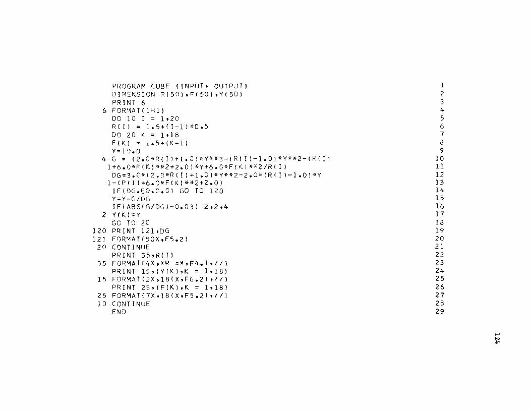
PROGRAM CUBE (INPUT, OUTPUT) DIMENSION R(50),F(50),Y(501 PRINT 6
6 FOR:'~AT( IHl) DO 10 I = 1,20 R(l) = 1.5+(1-11*0.5 DO 20 K = 1918 F(K) = 1.5+(K-l) Y=10.0
4 G = (2.0*R(I)+I.C)*Y**3-(R(I)-1.0)*Y**2-(RCII 1 + 6 • 0 * F ( K ) * * 2 + 2 • 0 ) * Y + 6 • C * F ( K ) ** 2 1 R ( I I DG=3.0*(Z.O*R(I)+1.01*Y**2-2.0*(Rlll-l.01*Y
1-(P(II+6.0*FIK)**2+2.01 IF(DG.EG.O.O) GO TO 120 Y=Y-G/DG IF(ABS(G/DGI-O.03) 2,2,4
2 Y(KI=Y GO TO 20
120 PRINT 121,DG 12J FOR~AT(50X,F5.2)
2 () CON TI NllE PRINT 35,R( I)
35 FOR~AT{4X,*R =*,F4.1,111 PRINT 15,(Y(K),K = 1,181
15 FORMAT(2X,r8(X,F6.21 ';/1 PRINT 25,(F(KI,K = 1,18)
25 FORMAT(7X,18(X,F5.2),II) 10 CONTINUE
END
1 2 3 4 5 6 7 8 9
10 11 12 13 14 15 16 17 18 19 20 21 22 23 24 25 26 27 28 29

APPENDIX B
DESIGN AND EXPERIMENTAL RESULTS OF A TYPICAL
CULVERT AND ENERGY DISSIPATOR INSTALLATION
In order to investigate the validity and workability of the design
procedure outlined in Chapter 4, several dimensional configurations for
two prototype structures were selected based on a set of existing field
conditions provided by Texas Highway Department. The information supplied
by the above agency included such features as the topography of the area,
road dimensions of highway crossing, design discharge, and the available
headwater depth at culvert inlet. The recommended design details of one
of these structures is outlined herein to serve as a guide to those using
the design procedure described in Chapter 4.
Statement of the Problem
A design discharge of 120 cfs is delivered to a highway crossing.
The highway dimensions, culvert inlet elevation, downstream natural
channel elevation, and the available headwater depth are shown in Figure lB.
The natural channel had a trapezoidal cross section with 1.5:1 side slopes.
Design a culvert and a radial flow energy dissipator at the culvert outlet.
As shown in Figure lB:
Inlet Flow Line Elevation 87. 0'
Road Surface Elevation 100.0'
Downstream Flow Line Elevation 82.3'
Available Headwater Depth 5.0'
Available Tailwater Depth 1.5'
125

\. 75'
i
~ 22' ·1· 22'
~ 2B)
4' x 4' + x 100'-
Concrete Culvert ~=5~,Tr~------------~~~~~~------------~~~-F.L. 87.0' 0.4% slope F. L. El. 86.6' wingwa11 e 1.
E1. 81.3'
Scale: 1" IS'
FIG. 1B TYPICAL HIGHWAY CULVERT INSTALLATION AND ENERGY DISSIPATOR

127
Design Procedure
Stepwise method of computations includes (I) design of culvert
dimensions, (II) design of entrance channel components, (III) selection of
stilling basin dimensions, and (IV) design of transition section from the
stilling basin to the trapezoidal downstream channel. Detail computations
of each step is as follows:
Step I - Culvert Design: Assume the first trial value of a box
culvert having square-edged entrance and:
b
d
4'
4'
g b
120 4
Culvert width
Culvert height
30
From chart 17-29, page 498, Chow (16), Hid 1.25, where H is the head-
water depth. Therefore,
H 1.25d 1.25 (4) 5.0'
Since the computed headwater depth is equal to the available headwater
depth, the trial box size of 4' x 4' is recommended as the actual culvert
size to be used. Computing the critical depth within the box culvert
results:
Yc ~:ff. b
2 g
A = by 4 x 3 c c
A 12.0 R
c c p 10.0
1 (120)2
(4)2(32.2) 3.0'
critical depth of flow in culvert
2 12 ft. crit ical area in culvert
1.2' critical hydraulic radius

n == 0.012 Manning roughness coefficient for concrete pipe
128
S c
(_----.:lQ~n ----:,.-;-:-) 2/3
1.49 A R
2 Manning equation - critical slope of flow
S c
c c
r 120 (.012) ]
L 1.49 (12) (1.2)2/3
Assume S 0.4% a
AR2/3 Q n
b 8/3 1.49 (S ) 1/2 (b) 8/3 a
2 0.0049 or 0.49/0
Slope of the culvert
120 (.012)
1.49 (.063 ) (40)
From charts Yn
in page 130 Chow (1G), b 0.82
0.38
0.82 (4) 3.28' Normal depth of flow in culvert
Since S S a < c'
Final culvert design details are:
Critical depth of flow occurs at the outlet of culvert just upstream of entrance channel.
Culvert Inlet F. L. Elevation == 87.0'
Culvert Outlet F. L. Elevation 86.6 '
Culvert Size 4' X 4' X 100'
Slope of Culvert (Mild) 0.4%
Flow Depth at Culvert Outlet 3.0'
Step II - Entrance Channel Components: Assume the maximum allow-
able negative pressure head on the curved section (P2/ Y ) to be - Y t' and
the point of curvature of the entrance channel vertical curve start at
exactly the outlet of the culvert, then:

1.0 and y t
129
3.0 feet
Determine the magnitude of the radius of curvature (R) from equation (4.13)
as follows:
1.5 1 Loge (1 + ~)
R 0.86 ft.
Note that the minimum required radius is 0.86 ft.; however, the geometry
of the area requires a larger radius. Thus a radius of 3.5 ft. is
recommended.
Use R 3.5'
Deflection angle between the tangent section to the downstream end of entrance channel vertical curve and horizontal stilling basin bottom.
The height of the wingwalls and the width of the entrance channel along
with other pertinent information are shown in Figures 2B and 3B.
Step III - Stilling Basin Design: The beginning width of the
basin is set as the width of entrance channel which is 4' while the end
width of the basin is fixed by the geometry of the area to be 11.8' which
is the top width of the downstream channel. Select the first trial value
of basin length (L) along the centerline by letting L
basin's geometry compute,
tan Q 3.9 12
0.325
12.0'. From the
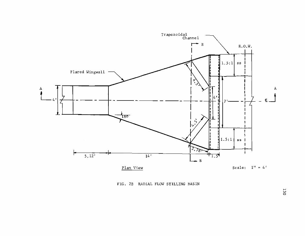
Flared Wingwall
5.12'
Plan View
Trapezoidal Channel
r-- B
I
I ~0' , I I I
I "
I\;< ~
FIG. 2B RADIAL FLOW STILLING BASIN
1.5:1 55
I I I A I
¢.~ 4' I I 7'---I I I I I I
I I I I 1.5: 1 55 I I I
Scale: 1" 4'

4'
E1. 86.6'
, r 3.0
~ __ \ Embankment 3:1
-....------ ----.... Top of Wingwalls
- El. 85.8' - -........
F181.3'
k·64' ~ 14'
Elevation View-Section AA
FIG. 3B RADIAL FLOW STILLING BASIN
R.O.W. I I I I I I I ........ ~------I
2'-.... - I I
Scale 1" = 4'

132
End Sill
1. 51
2 I
11
Triangular Walls
\. 3.G5 I
·1-41 3.65
·1 Section BB
FIG. 4B VIEW OF THE TRANSITIONAL SECTION AND THE END SILL

133
Flared angle of wingwalls
Set the elevation of the horizontal bottom of stilling basin at 81.3 1 to
account for a II end sill. Now the index depth at the beginning of the
basin could be determined by using Bernoullils equation between this
section and the outlet of culvert, neglecting frictional losses, as
follows:
v2
c + Yc + Z 2g
2 (Q/by f)
2g
2 (120~ + 3.0 + 5.3
900 --2 + Yf 2g Y
f
Solving for Yf
results:
1.28 1 The index depth at the beginning of basin
From the geometry of the basin:
b 2 Sin 9
Radial distance from the intersection of the flared wingwalls to the beginning of basin.
4.0 r = -~..;...;:.--f 2 Sin 180
6.5 1
Assuming negligible boundary friction for supercritical flow equation
(4.27) may be evaluated as follows:
6.5 (1. 28) = 8 .31 constant
Using equation (4.26):

(360)Q 360 (120) 2 TT (36) 8. 31
22.9 fps
134
Supercritical velocity at the beginning of bas in.
Since x is the distance along the centerline from the beginning of the
basin to the leading edge of the jump, then
Assume x = 0, and 2Yf' where Yf
= 1.28, and compute the sequent depth of
the hydraulic jump (Y2
) and the radial distance to the end of the jump (r2)
through the simultaneous solution of equations (2.6) and (4.24) as follows:
Case 1: When x = 0
2.29
(32.2 (1.28,)
1.28'
6.5'
22.9 fps
3.57 Froude number upstream from the jump.
Substituting above numerical values and simplifying equations (4.24) and
(2.6) one gets:
12.2 Y2 1.28+ 0.47 From equation (4.24)
r 2
r2
Y2 -0.35 + ~ From equation (2.6)
Solving for r 2 and Y2"

Case II:
r 2 = 18.8'
Y2 4.35'
18.8 - 6.5 12.3'
When x = 2y f
2.56'
Jump length
rl
rf
+ x = 6.5' + 2.56' 9.06'
r f Y f 8.31 0.92' Yl rl
= 9.06
v = 1
22.9 s
22.9 4 2 -;:========= = • /32.2 (0.92)
135
Substitut above numerical values and simplifying equations (4.24) and
(2.6) results in:
Y2
Y2
Solving r 2 and Y2'
From equation (4.24)
r2
-1.34 + ""4 From equation (2.6)
21. 2'
Y = 3.94' 2
r = 21.3 - 9.06 1
11. 24 I
The assumed length of the basin of 12' would be small if the jump had to

136
occur downstream from x = 2Yf' In order to accommodate the transition
section and also provide a factor of safety for jump confinement within the
basin, total basin length of 14' is recommended. Figures 2B, 3B, and 4B
show the details of basin dimensions. Step III computation indicate the
approximate position of the leading edge of the jump. As shown in these
figures:
L 14'
Height of Wingwalls 4.5'
The recommended height of the wingwall would provide sufficient freeboard
for safe operation of the basin.
Step IV - Design of the Transition Section and the End Sill: It
should be noted that so far the computations were conducted on the basis
of a rectangular downstream channel. The selection of the dimensions of
converging triangular walls is based on the recommendations outlined in
Chapter 4. The base length of the triangular wall is 4.5' which is equal to
the projected length of the edge of the triangular surface along the side
slope of the downstream channel on the bottom of the basin. The apex of
the triangular wall is set at elevation 84.3' which is the point of inter-
section of the flared wingwalls and the side slope of trapezoidal down-
stream channel. The details of the transition section are shown in
Figures 2B, 3B, and 4B.
The height of the sill (H ) was previously assumed to be 1.0' in s
order that the elevation of the bottom of stilling basin could be computed.
The workability of the assumed height must now be checked. Application of

equation (4.32) determines the depth of flow on the sill as follows:
2 V3 - + Y3 + H 2g s
Equation (4.32)
l37
Average velocity on the sill
When the leading edge of the jump is at x 2Yf' calculations showed that
Y2 3.94' and hence,
3.94
Above relationship results in Y3 1.35' when the height of the sill is
1.0'. Thus, the recommended height of the sill is:
H s
1.0' Sill height
The critical depth of flow on the sill is calculated as follows:
Ycs (7 + 1.5 Ycs ) D 7 + 3 Ycs
9. 120 V cs A Y (7 + 1. 5
c
(120)2
Yc )
V2 cs
2g
Critical hydraulic depth on sill
Critical velocity on sill
D
2
Ycs (7 + 1.5 Ycs )
2(7+3y) cs
y could be solved by trial and error to be: cs
1. 8' Critical depth of flow on sill

138
Since y >Y3 the flow would go through critical depth at the brink and cs
the depth of downstream channel in the vicinity of the stilling basin
should be 2.5' to provide sufficient depth for flow plus freeboard. Since
the allowable tailwater depth is only 1.5', an improvement in the down-
stream trapezoidal channel is recommended to maintain the required height
plus freeboard as shown in Figures 2B and 3B.
Experimental Results
In order to determine the effectiveness and performance character-
istics of the recommended structure, a model of this energy dissipator
having a scale ratio of 1:3 was constructed and tested at Balcones Research
Center, The University of Texas at Austin. A photographic view of the
model with and without flow is shown in Figure 5B. The discharge was
delivered to a stilling tank from a 6" diameter supply pipe and was
measured by a sharp crested weir after it left the dissipating structure.
The stilling tank was 4' x 4' X 8' having a transverse screen within it to
damp out the flow disturbance. A horizontal box culvert 8.0' long con-
veyed the flow from the tank to the entrance channel. All entrance
channel, stilling basin, and downstream cross section dimensions were
1/3 of the ones recommended in the design section. A 16' horizontal
trapezoidal downstream channel was constructed to minimize the downstream
effects on the performance of the dissipating structure.
The experimental procedure included the measurements of the depth
of flow at the outlet of the box culvert, the position of the leading edge
of the jump, the sequent depths of the hydraulic jump, the depth of flow
in the downstream channel, and the velocities in transverse as well as

(a) With Flow (b) Without Flow
FIG. sa PHOTOGRAPHIC VIEW OF THE MODEL AT BALCONES CENTER

140
longitudinal sections of the downstream channel. Although it was desir-
able to have a discharge of 7.5 cfs; however, the pumps and the piping
arrangements limited the flow delivery to maximum of 5.0 cfs. Hence, the
experiments were conducted within the available range of discharge.
Satisfactory performance was observed for the range of flow
variables tested as shown in Table lB. The hydraulic jump was formed
within the basin as anticipated. Froude numbers Ft
in excess of design
values were provided to test the effective performance of the dissipator.
As shown in Table lB, Ft
of 1.71 resulted in satisfactory performance.
Velocity measurements were obtained at 0.03 foot and at 0.4Y3
from the channel bottom in the downstream channel to determine the trans-
verse velocity distribution and the degree of velocity reduction within
the basin. The relative velocity ratio V/V at each section is shown in m
Figure 6B. The velocity ratio V/V was fairly uniform in any transverse m
section for a given set of hydraulic conditions. A relatively high degree
of velocity reduction was observed in all experiments. Analyses of
velocity profiles showed that for sections farthest downstream the
velocities were reduced to an approximate range of 25 to 65 percent of
Vt
• The general performance of the structure was satisfactory as a
radial flow energy dissipator.

141
TABLE 1B
Design Data Experimental Results
Q = 7.5 cfs Q = 4.8 cfs Q = 4.8 cfs Q = 4.0 cfs Q = 4.0 cfs
Ft = 1.0 Ft 1.08 Ft 1.71 Ft = 1.05 Ft = 1.57
Yt 1.0' Yt 0.70' Yt
0.517' Yt = 0.64' Yt = 0.48'
x = 0.9' x = 1. 5' x = 1. 9' x = 1.50' x = 1.6 '
Y1 0.2' Y1 0.23' Y1 0.22' Y1 = 0.23 ' Y1 = 0.19'
Y2 1. 3' Y2 0.89' Y2 0.95' Y2 = 0.83' Y2 = 0.89'
Y3 0.45' Y3 0.51' Y3 = 0.53' Y3 0.40' Y3 = 0.40'
Ys 0.6' Ys 0.56' Ys
= 0.61' Ys 0.49' Ys = 0.57'

Leading Edge of the Jump
5'
Leading Edge of the Jump
5'
v/V m
v/V m
1. 08, Q 4.8 cfs
Pitot Tube at 0.03'
3' 3'
\
----+-- - fe----
o 1 2
Pitot Tube at 0.4Y3
3'
/
o 1
3'
, \ ~
I
o 2
142
1 '
1-
l'
1 '
o 1--
o 1 2
o 3
1 2
FIG. 6B RELATIVE VELOCITY PATTERN IN DOWNSTREAM CHANNEL