Embed Size (px)
Citation preview
Tailor Made Concrete Structures – Walraven & Stoelhorst (eds)© 2008 Taylor & Francis Group, London, ISBN 978-0-415-47535-8
Design approach for diaphragm action of roof decks in precast concretebuilding under earthquake
L. Ferrara & G. TonioloDepartment of Structural Engineering, Politecnico di Milano, Milan, Italy
ABSTRACT: The response of a structure to earthquake relies on the diaphragmatic behaviour of slabs at bothstorey and roof level. Cast-in-situ r/c slabs can easily behave as rigid diaphragm. The same holds for slabs builtwith precast elements and completed through in situ casting, provided peripheral ties and suitable reinforcementat connections with vertical elements is provided. Long span roofing of precast r/c industrial buildings generallyconsist of “panel elements” connected through mechanical devices, without any cast-in-situ completion, or eveninterposed with skylights. Diaphragm action can be still relied upon if the in plane rotational equilibrium ofelements can be guaranteed by forces at peripheral connections: for this case a simplified design approach isproposed and validated in this paper.
1 INTRODUCTION
Seismic design of building structures is aimed atproviding lateral-force resisting systems with suffi-cient strength, stiffness and ductility to ensure a safebehaviour during earthquakes. In the whole procedurea key role is played by the diaphragm behaviour offloor and roof systems, which transfer seismic forcesat each level in a uniform way to the vertical elementsof the resisting system. Poor building behavioursand even collapses due to improperly designed anddetailed diaphragms and connections were reportedin several earthquakes during last decades. For exam-ple, the collapse of several parking structures duringNorthridge earthquake (1994) was rightly attributedto a neglected/underestimated diaphragm flexibility.This deficiency caused drift demands for which theelements of the gravity load resisting system were notdesigned and which increased second order effects ofgravity loads (Fleischmann et al., 1998; Wood et al.,2000; Farrow and Fleischmann, 2003; Fleischmannand Farrow, 2004).
The in-plane stiffness of floor and roof systemsgenerates structure redundancy towards earthquakeactions, and consequently provides restraint of uncou-pled equilibrium deformations of vertical subsys-tems. This gives rise to compatibility forces in thediaphragm, besides equilibrium forces.The magnitudeof compatibility forces depends on the in-plane dis-tribution and orientation of vertical subsystems and
on their relative stiffness. In order to properly andeffectively generate diaphragm action, the requiredstiffness of horizontal subsystems must be accompa-nied by sufficient strength to withstand the resultingcompatibility forces.
Two main issues have hence to be considered in theseismic design of diaphragms: the proper evaluationof in-plane seismic forces, namely their values anddistribution along the height of the building, and howthese forces are transmitted to vertical elements, whichresist the lateral actions.
The present study is focused on precast one storeybuildings, as widely used for industrial and commer-cial halls.
Floor and roof systems normally employed in pre-cast structures consist of an assembly of panels suchas double-tee units, connected to each other by pointconnections along the slab edges. Since these elementspossess a large in-plane stiffness, seismic design ofprecast diaphragms is essentially a connection designproblem (Clough, 1982; Davies et al., 1990). Also spe-cial roof elements are employed, made of thin walledfolded plates of different shapes, normally 2.5 m wideand up to 20–25 m long, laid in alternatively withskylights (Fig. 1) These elements are connected tothe beams through pins or other suitable mechanicaldevices, which, besides preventing from the loss ofseating during earthquake induced, have to be designedto transmit in-plane diaphragm forces, according toa suitable design model as illustrated in forthcoming
963
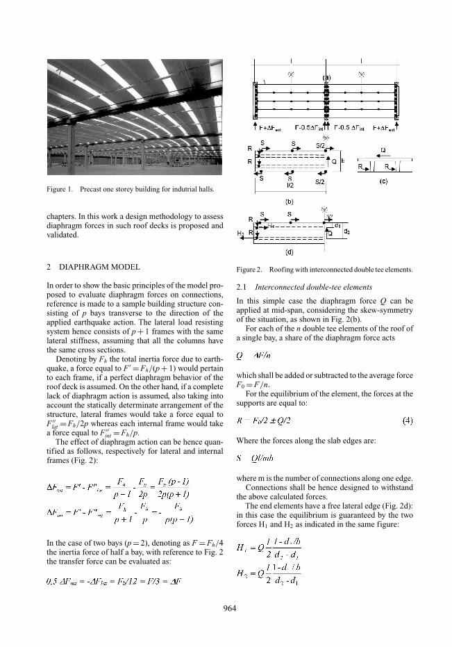
Figure 1. Precast one storey building for indutrial halls.
chapters. In this work a design methodology to assessdiaphragm forces in such roof decks is proposed andvalidated.
2 DIAPHRAGM MODEL
In order to show the basic principles of the model pro-posed to evaluate diaphragm forces on connections,reference is made to a sample building structure con-sisting of p bays transverse to the direction of theapplied earthquake action. The lateral load resistingsystem hence consists of p + 1 frames with the samelateral stiffness, assuming that all the columns havethe same cross sections.
Denoting by Fh the total inertia force due to earth-quake, a force equal to F ′ = Fh/(p + 1) would pertainto each frame, if a perfect diaphragm behavior of theroof deck is assumed. On the other hand, if a completelack of diaphragm action is assumed, also taking intoaccount the statically determinate arrangement of thestructure, lateral frames would take a force equal toF ′′
lat = Fh/2p whereas each internal frame would takea force equal to F ′′
int = Fh/p.The effect of diaphragm action can be hence quan-
tified as follows, respectively for lateral and internalframes (Fig. 2):
In the case of two bays (p = 2), denoting as F = Fh/4the inertia force of half a bay, with reference to Fig. 2the transfer force can be evaluated as:
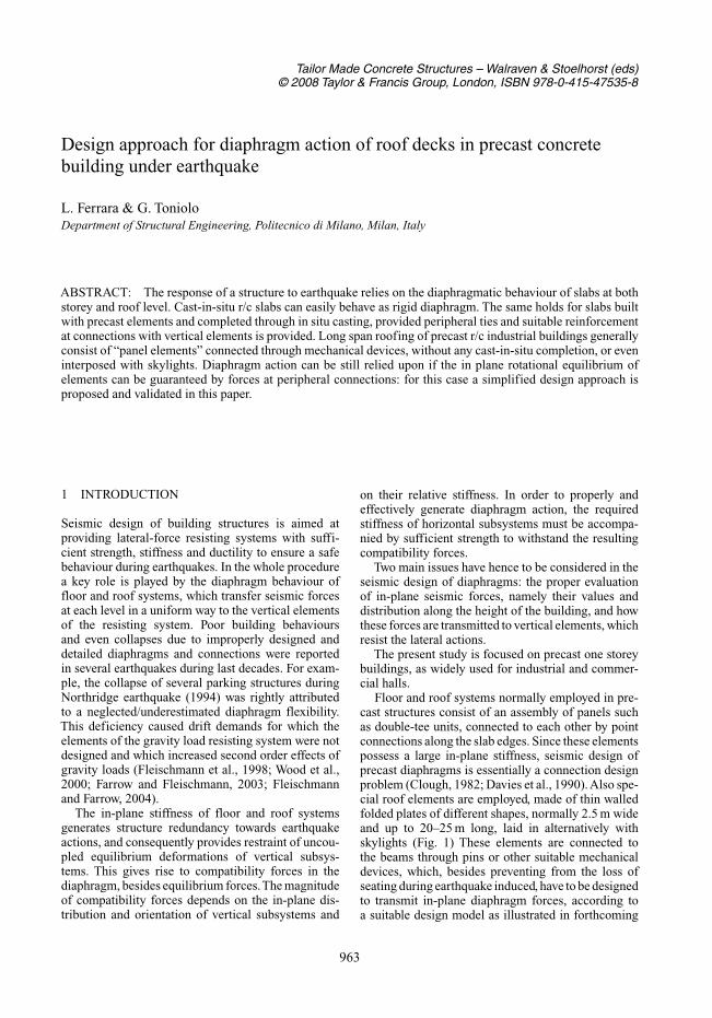
Figure 2. Roofing with interconnected double tee elements.
2.1 Interconnected double-tee elements
In this simple case the diaphragm force Q can beapplied at mid-span, considering the skew-symmetryof the situation, as shown in Fig. 2(b).
For each of the n double tee elements of the roof ofa single bay, a share of the diaphragm force acts
which shall be added or subtracted to the average forceF0 = F/n.
For the equilibrium of the element, the forces at thesupports are equal to:
Where the forces along the slab edges are:
where m is the number of connections along one edge.Connections shall be hence designed to withstand
the above calculated forces.The end elements have a free lateral edge (Fig. 2d):
in this case the equilibrium is guaranteed by the twoforces H1 and H2 as indicated in the same figure:
964
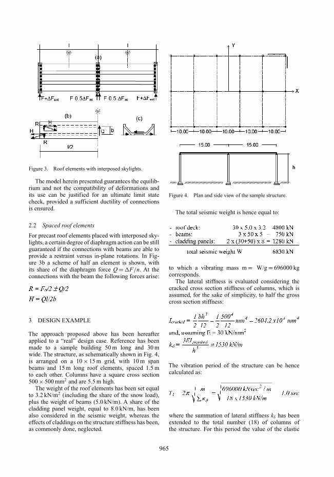
Figure 3. Roof elements with interposed skylights.
The model herein presented guarantees the equilib-rium and not the compatibility of deformations andits use can be justified for an ultimate limit statecheck, provided a sufficient ductility of connectionsis ensured.
2.2 Spaced roof elements
For precast roof elements placed with interposed sky-lights, a certain degree of diaphragm action can be stillguaranteed if the connections with beams are able toprovide a restraint versus in-plane rotations. In Fig-ure 3b a scheme of half an element is shown, withits share of the diaphragm force Q = �F/n. At theconnections with the beam the following forces arise:
3 DESIGN EXAMPLE
The approach proposed above has been hereafterapplied to a “real” design case. Reference has beenmade to a sample building 50 m long and 30 mwide. The structure, as schematically shown in Fig. 4,is arranged on a 10 × 15 m grid, with 10 m spanbeams and 15 m long roof elements, spaced 1.5 mto each other. Columns have a square cross section500 × 500 mm2 and are 5.5 m high.
The weight of the roof elements has been set equalto 3.2 kN/m2 (including the share of the snow load),plus the weight of beams (5.0 kN/m). A share of thecladding panel weight, equal to 8.0 kN/m, has beenalso considered in the seismic weight, whereas theeffects of claddings on the structure stiffness has been,as commonly done, neglected.
Figure 4. Plan and side view of the sample structure.
The total seismic weight is hence equal to:
to which a vibrating mass m = W/g = 696000 kgcorresponds.
The lateral stiffness is evaluated considering thecracked cross section stiffness of columns, which isassumed, for the sake of simplicity, to half the grosscross section stiffness:
The vibration period of the structure can be hencecalculated as:
where the summation of lateral stiffness kδ has beenextended to the total number (18) of columns ofthe structure. For this period the value of the elastic
965
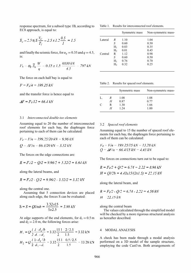
response spectrum, for a subsoil type 1B, according toEC8 approach, is equal to:
and finally the seismic force, forαg = 0.35 and q = 4.5,is:
The force on each half bay is equal to
and the transfer force is hence equal to
3.1 Interconnected double-tee elements
Assuming equal to 20 the number of interconnectedroof elements for each bay, the diaphragm forcepertaining to each of them can be calculated:
The forces on the edge connections are:
along the lateral beams, and
along the central one.Assuming that 5 connection devices are placed
along each edge, the forces S can be evaluated:
At edge supports of the end elements, for d1 = 0.5 mand d2 = 2.0 m, the following forces arise:
Table 1. Results for interconnected roof elements.
Symmetric mass Non-symmetric mass-
Lateral R 1.10 1.04S 0.60 0.50H1 0.03 0.35H2 0.01 0.45
Central R 1.12 0.98S 0.60 0.50H1 0.76 0.70H2 0.32 0.25
Table 2. Results for spaced roof elements.
Symmetric mass Non-symmetric mass-
L. R 1.08 1.08H 0.87 0.77
C R 1.30 1.66H 1.24 1.00
3.2 Spaced roof elements
Assuming equal to 15 the number of spaced roof ele-ments for each bay, the diaphragm force pertaining toeach of them can be calculated:
The forces on connections turn out to be equal to:
along the lateral beam, and
along the central beamThe values calculated through the simplified model
will be checked by a more rigorous structural analysisas hereafter described.
4 MODAL ANALYSIS
A check has been made through a modal analysisperformed on a 3D model of the sample structure,employing the code Cast3 m. Both arrangements of
966
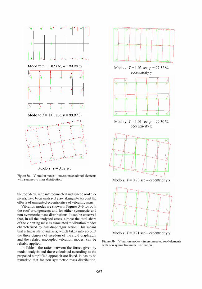
Figure 5a. Vibration modes – interconnected roof elementswith symmetric mass distribution.
the roof deck, with interconnected and spaced roof ele-ments, have been analyzed, also taking into account theeffects of uninented eccentricities of vibrating mass.
Vibration modes are shown in Figures 5–6 for boththe roof arrangements and for either symmetric andnon-symmetric mass distributions. It can be observedthat, in all the analyzed cases, almost the total shareof the vibrating mass is associated to vibration modescharacterized by full diaphragm action. This meansthat a linear static analysis, which takes into accountthe three degrees of freedom of the rigid diaphragmand the related uncoupled vibration modes, can bereliably applied.
In Table 1 the ratios between the forces given bymodal analysis and those calculated according to theproposed simplified approach are listed. It has to beremarked that for non symmetric mass distribution,
Figure 5b. Vibration modes – interconnected roof elementswith non symmetric mass distribution.
967
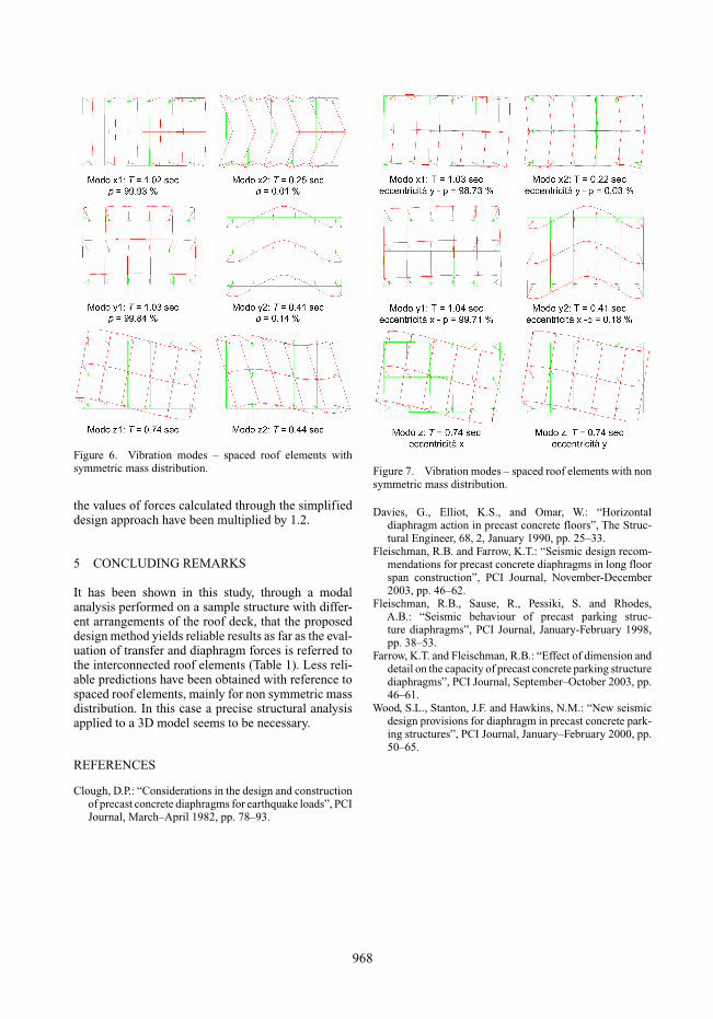
Figure 6. Vibration modes – spaced roof elements withsymmetric mass distribution.
the values of forces calculated through the simplifieddesign approach have been multiplied by 1.2.
5 CONCLUDING REMARKS
It has been shown in this study, through a modalanalysis performed on a sample structure with differ-ent arrangements of the roof deck, that the proposeddesign method yields reliable results as far as the eval-uation of transfer and diaphragm forces is referred tothe interconnected roof elements (Table 1). Less reli-able predictions have been obtained with reference tospaced roof elements, mainly for non symmetric massdistribution. In this case a precise structural analysisapplied to a 3D model seems to be necessary.
REFERENCES
Clough, D.P.: “Considerations in the design and constructionof precast concrete diaphragms for earthquake loads”, PCIJournal, March–April 1982, pp. 78–93.
Figure 7. Vibration modes – spaced roof elements with nonsymmetric mass distribution.
Davies, G., Elliot, K.S., and Omar, W.: “Horizontaldiaphragm action in precast concrete floors”, The Struc-tural Engineer, 68, 2, January 1990, pp. 25–33.
Fleischman, R.B. and Farrow, K.T.: “Seismic design recom-mendations for precast concrete diaphragms in long floorspan construction”, PCI Journal, November-December2003, pp. 46–62.
Fleischman, R.B., Sause, R., Pessiki, S. and Rhodes,A.B.: “Seismic behaviour of precast parking struc-ture diaphragms”, PCI Journal, January-February 1998,pp. 38–53.
Farrow, K.T. and Fleischman, R.B.: “Effect of dimension anddetail on the capacity of precast concrete parking structurediaphragms”, PCI Journal, September–October 2003, pp.46–61.
Wood, S.L., Stanton, J.F. and Hawkins, N.M.: “New seismicdesign provisions for diaphragm in precast concrete park-ing structures”, PCI Journal, January–February 2000, pp.50–65.
968