Embed Size (px)
Citation preview

Design and Use of Containers for Cryogenic Liquids Cryogenic liquid containers of a nominal 165 liter (43.6 gal.) capacity from three domestic manufacturers were tested and compared.
Walter Shattes, The BOC Group, Technical Center, 100 Mountain Ave., Murray Hill, New Providence, NJ 07974.
INTRODUCTION
The use of cryogenic liquid containers for gas delivery and storage is increasing because they take up only one fourth the floor space of high pressure compressed gas cylinders holding the equivalent gas volume, require less frequent connection changes and consistently deliver a high purity product. Because of recent changes in design and con- struction, the BOC Group Inc. felt that a practical evalua- tion and a comparison of various manufacturers’ liquid containers were appropriate.
Containers of 165 liter (43.6 gal.) nominal capacity were obtained from three US. manufacturers. They are re- quired to meet DOT 4L specifications with a DOT service pressure of 1.379 MPa (200 psig). Design specifications are given in Table I. These containers included units with stainless steel outer shells from all three manufacturers as well as carbon steel outer shells from two of them. The evaluation consisted of both performance tests and tests to determine the capacity to withstand physical abuse as well as an examination of the design and construction details of each.
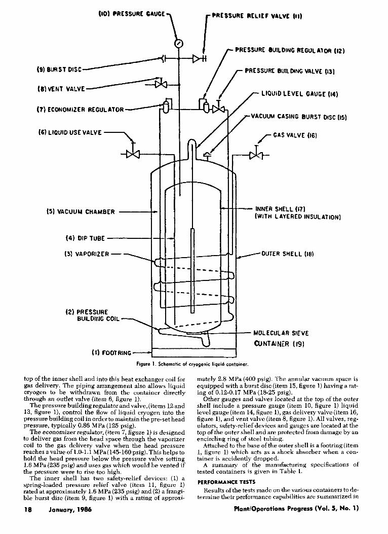
A schematic diagram for a typical cryogenic liquid con- tainer is shown in Figure 1. The inner shell (item 17, figure 1) that holds the liquid cryogen, is made of 304 stainless steel, while the outer shell (item 18, figure 1) is
made of either stainless or carbon steel. The outside wall of the inner shell is wrapped with alternating layers of alu- minum foil and glass-fiber paper to minimize radiative heat transfer to the inner shell. The annular region (item 5, figure 1) between the shells is evacuated for increased thermal isolation. In addition, a perforated pan (item 19, figure 1) is attached to the outer wall of the inner shell and is used to hold molecular sieve in order to maintain the in- tegrity of the vacuum by adsorbing residual gases. Since molecular sieves are not effective in adsorbing hydrogen, a small packet of palladium oxide is provided to adsorb re- sidual hydrogen gas. The palladium oxide is held in a packet formed by folding a fine mesh screen. Support con- nections between shells are at the top and bottom. The top support is a neck tube that also provides access to the liq- uid reservoir. The configuration of the lower support varies with the manufacturer.
Two heat exchanger coils are soft soldered to the inner wall ofthe outer shell and convert liquid cryogen from the inner shell to gas. The shorter heat exchanger is the pres- sure building coil (item 2, figure 1). It takes cryogen di- rectly from the bottom ofthe inner shell and delivers gas to the region above the liquid to provide a pressure head for product delivery. The longer heat exchanger is the vapori- zer ( i tem 3, figure 1) . Liquid cryogen is conducted through a dip tube (item 4, figure 1) from the bottom to the
Manufacturer
Diameter Height Weight (nominal) Weight of Contents
Argon Nitrogen Oxygen
Argon Nitrogen Oxygen
Gas Equivalent (NTP)
Cont. Gas Delivery Rate Normal Daily Evaporation Rate (% of Capacity)
Nitrogen Oxygen of Argon
Rated DOT Service Pressure Inner Container Burst
Vacuum Jacket Burst Disc Rating
Disc Rating
TABLE I. MANUFACTURER’S SPECIFICATION
A B
51 cm (20 in) 152 crn (60 in) 113 kg (250 Ib)
201.9 kg (445 Ib) 119.8 kg (264 lb) 169.2 kg (373 Ib)
51 cm (20 in) 161 cm (63 112 in) 113 kg (250 Ib)
201.9 kg (445 Ib) 119.8 kg (264 Ib) 169.2 kg (373 lb)
120 m3 (4320 CF) 101 m3 (3640 CF) 125 rn3 (4500 CF) 9.0 m3/hr (325 CFH)
120 m3 (4320 CF) 101 rn3 (3640 CF) 125 m3 (4500 CF) 9.7 m3/hr (350 CFH)
2.2%lday 2.2%/day 1.5%/day 1.5%/day 1.379 MPa (200 psig)
2.785 MPa (400 psig)
1.379 MPa (200 psig)
2.785 MPa (400 psig)
103-124 kPa (15-18 psig)
172 kPa (25 psig)
C
51 cm (20 in) 158 cm (62 114 in) 113 kg (250 Ib)
202.8 kg (447 Ib) 119.9 kg (264 Ib) 169.2 kg (373 Ib)
120 m3 (4320 CF) 101 m3 (3640 CF) 125 rn3 (4500 CF) 6.9 m3/hr (250 CFH)
2.4%/day 1.5%lday 1.379 MPa (ZOO psig)
2.620 MPa (380 psig)
124 kPa (18 psig)
Want/Operations Progress (Vol. 5, No. 1) Jonuory, 1986 17
15) VACUUM CHAMBER
(4) DIP TUBE
(3) VAPORIZER - 1
(2) PRESSURE - BULDlfJG COIL
(1) FOOTRING -
410) PRCSSURE GAUGE
PRESSURE 8UILDING REGUL A1
PRESSUK BUILDNC VALVE
(7) ECONOMIZER REGULATOR
(6) LtQUlO USE VALVE
-- d b
* - - - - - - - _ _ _ + r
---- -- - -___ -
c-
MOLECULAR SIEVE
CuNTAlNER (19)
LtOUlO LEVEL GAUGE 114)
/- VACUUM CASING BURST DISC (IS)
/- T
(WITH LAYERED INSULATION) It INNER SHELL (17) (WITH LAYERED INSULATION)
/OUTER SHELL (lei
Figure 1. Schematic of cryogenic liquid container.
top of the inner shell and into this heat exchanger coil for gas delivery. The piping arrangement also allows liquid cryogen to be withdrawn from the container directly through an outlet valve (item 6, figure 1).
The pressure building regulator and valve,(items 12 and 13, figure l ) , control the flow of liquid cryogen into the pressure building coil in order to maintain the pre-set head pressure, typically 0.86 MPa (125 psig).
The economizer regulator, (item 7, figure 1) is designed to deliver gas from the head space through the vaporizer coil to the gas delivery valve when the head pressure reaches a value of 1.0-1.1 MPa( 145-16Opsig). This helps to hold the head pressure below the pressure valve setting 1.6 MPa (235 p i g ) and uses gas which would be vented if the pressure were to rise too high.
The inner shell has two safety-relief devices: (1) a spring-loaded pressure relief valve (item 11, figure 1) rated at approximately 1.6 MPa (235 psig) and (2) a frangi- ble burst disc (item 9, figure 1) with a rating of approxi-
18 January, 1986
mately 2.8 MPa (400 psig). The annular vacuum space is equipped with a burst disc (item 15, figure 1) having a rat- ing of 0.12-0.17 MPa (18-25 psig).
Other gauges and valves located at the top of the outer shell include a pressure gauge (item 10, figure 1) liquid level gauge (item 14, figure l) , gas delivery valve (item 16, figure l), and vent valve (item 8, figure 1). All valves, reg- ulators, safety-relief devices and gauges are located at the top of the outer shell and are protected from damage by an encircling ring of steel tubing.
Attached to the base of the outer shell is a footring (item 1, figure 1) which acts as a shock absorber when a con- tainer is accidently dropped.
A summary of the manufacturing specifications of tested containers is given in Table I.
PERFORMANCE TESTS Results ofthe tests made on the various containers to de-
termine their performance capabilities are summarized in
Plant/Operotions Progress (Vol. 5, No. 1)
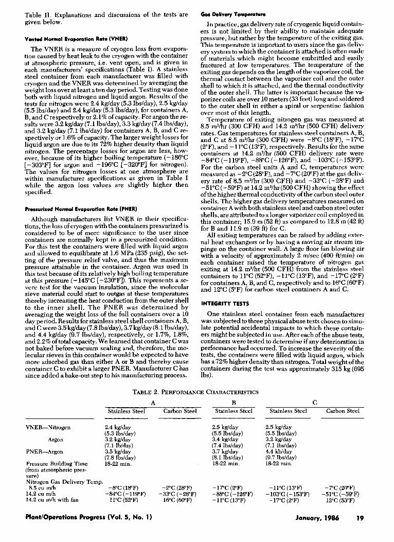
Table 11. Explanations and discussions of the tests are given below.
Vented Normal Evaporation Rote (VNER)
The VNER is a measure of cryogen loss from evapora- tion caused by heat leak to the cryogen with the container at atmospheric pressure, i.e. vent open, and is given in each manufacturers' specifications (Table I). A stainless steel container from each manufacturer was filled with cryogen and the VNER was determined by averaging the weight loss over at least a ten day period. Testing was done both with liquid nitrogen and liquid argon. Results of the tests for nitrogen were 2.4 kglday (5.3 lbdday), 2.5 kglday (5.5 lbdday) and 2.4 kglday (5.3 lbdday), for containers A, B, and C respectively or 2.1% of capacity. For argon the re- sults were 3.2 kglday (7.1 lbs/day), 3.3 kglday(7.4 lbs/day), and 3.2 kglday (7.1 lbs/day) for containers A, B, and C re- spectively or 1.6% of capacity. The larger weight losses for liquid argon are due to its 72% higher density than liquid nitrogen. The percentage losses for argon are less, how- ever, because of its higher boiling temperature (- 186°C [-303"FI for argon and -196°C [-320"F] for nitrogen). The values for nitrogen losses at one atmosphere are within manufacturer specifications as given in Table I while the argon loss values are slightly higher then specified.
Pressurized Normal Evaporation Rote (PNER)
Although manufacturers list VNER in their specifica- tions, the loss ofcryogen with the containers pressurized is considered to be of more significance to the user since containers are normally kept in a pressurized condition. For this test the containers were filled with liquid argon and allowed to equilibrate at 1.6 MPa (235 psig), the set- ting of the pressure relief valve, and thus the maximum pressure attainable in the container. Argon was used in this test because of its relatively high boiling temperature at this pressure (-145°C [-230"F]). This represents a se- vere test for the vacuum insulation, since the molecular sieve material could start to outgas at these temperatures thereby increasing the heat conduction from the outer shell to the inner shell. The PNER was determined by averaging the weight loss of the full containers over a 10 day period. Results for stainless steel shell containers A, B, and C were 3.5 kglday(7.8 lbdday), 3.7 kglday(8.1 lbdday), and 4.4 kglday (9.7 lbdday), respectively, or 1.7%, 1.8%, and 2.2% of total capacity. We learned that container C was not baked before vacuum sealing and, therefore, the mo- lecular sieves in this container would be expected to have more adsorbed gas than either A or B and thereby cause container C to exhibit a larger PNER. Manufacturer C has since added a bake-out step to his manufacturing process.
Gas Delivery Temperature
In practice, gas delivery rate of cryogenic liquid contain- ers is not limited by their ability to maintain adequate pressure, but rather by the temperature of the exiting gas. This temperature is important to users since the gas deliv- ery system to which the container is attached is often made of materials which might become embrittled and easily fractured at low temperatures. The temperature of the exiting gas depends on the length of the vaporizer coil, the thermal contact between the vaporizer coil and the outer shell to which it is attached, and the thermal conductivity of the outer shell. The latter is important because the va- porizer coils are over 10 meters (33 feet) long and soldered to the outer shell in either a spiral or serpentine fashion over most of this length.
Temperature of exiting nitrogen gas was measured at 8.5 m3/hr (300 CFH) and 14.2 m3/hr (500 CFH) delivery rates. Gas temperatures for stainless steel containers A, B, and C at 8.5 m3/hr (300 CFH) were -8°C (18"F), -17°C (PF), and -11°C (13"F), respectively. Results for the same containers at 14.2 m3/hr (500 CFH) delivery rate were -84°C (-119"F), -88°C (-126"F), and -103°C (-153°F). For the carbon steel units A and C, temperatures were measured as -2°C (28"F), and -7°C (20°F) at the gas deliv- ery rate of 8.5 m3/hr (300 CFH) and -33°C (-28°F) and -51°C (-59°F) at 14.2 m3/hr (500 CFH) showing the effect of the higher thermal conductivity of the carbon steel outer shells. The higher gas delivery temperatures measured on container A with both stainless steel and carbon steel outer shells, are attributed to a longer vaporizer coil employed in this container; 15.9 m (52 ft) as compared to 12.8 m (42 ft) for B and 11.9 m (39 ft) for C.
All exiting temperatures can be raised by adding exter- nal heat exchangers or by having a moving air stream im- pinge on the container wall. A large floor fan blowing air with a velocity of approximately 2 m/sec (400 Wmin) on each container raised the temperature of nitrogen gas exiting at 14.2 mYhr (500 CFH) from the stainless steel containers to 11°C (52"F), -11°C (13"F), and -17°C (2°F) for containers A, B, and C, respectively and to 16°C (60°F) and 12°C (5°F) for carbon steel containers A and C.
INTEGRITY TESTS
One stainless steel container from each manufacturer was subjected to three physical abuse tests chosen to simu- late potential accidental impacts to which these contain- ers might be subjected in use. After each of the abuse tests, containers were tested to determine if any deterioration in performance had occurred. To increase the severity of the tests, the containers were filled with liquid argon, which has a 72% higher density than nitrogen. Total weight of the containers during the test was approximately 315 kg (695 lbs).
TABLE 2. PERFORMANCE CHARACTERISTICS
A B Stainless Steel Carbon Steel Stainless Steel
VNER-Nitrogen 2.4 kg/day
Argon 3.2 kg/day
PNER-Argon 3.5 kg/day
Pressure Building Time 18-22 min. (from atmospheric pres- sure) Nitrogen Gas Delivery Temp. 8.5 cu m/h -8°C (18°F) -2°C (28°F)
14.2 cu m/h -84°C (-119°F) -33°C (-28°F) 14.2 cu m/h with fan 11°C (52°F) 16°C (60°F)
(5.3 Ibslday)
(7.1 lb/day)
(7.8 Ibslday)
2.5 kg/day (5.5 lbs/day) 3.4 kg/day (7.4 lbs/day) 3.7 kglday (8.1 lbs/day) 18-22 min.
-17°C (2°F) -88°C (- 126°F) - 11°C (13°F)
C Stainless Steel Carbon Steel
2.5 kg/day (5.5 Ibs/day) 3.2 kg/day (7.1 lbdday) 4.4 kblday (9.7 lbs/day) 18-22 min.
- 11°C ( 13°F) -7°C (20°F) -103°C (-153°F) -51°C (-59°F)
-17°C (2°F) 12°C (53°F)
January, 1986 19 Plant/Operations Progress (Vol. 5, No. 1)

30 cm (1 ft) Drop Test
The first impact test was a drop from 30 cm (1 ft) to simulate an accidental fall from a crane or other lifting de- vice during moving or positioning of the container. Each container was lifted 30 cm (1 ft), tilted at an angle [see Fig- ure 21 so that the container would impact a flat steel plate with the edge of its footring, and return to an upright posi- tion after impact. Each container was dropped four times with impacts at approximately 90" intervals on the footring.
All containers had shock adsorbing capability built into the footring. Container A used an all metal structure whose cross section was in the shape of a "C", while containers B and C used rubber mounts between the footring and outer shell. All shock adsorbers proved effective as evidenced by the superficial damage done to each container in this test.
Following the four drops, the containers were checked for internal damage by measuring the argon VNER. No changes in cryogen evaporation rate were found, indicat- ing that no functional damage was sustained by interior parts.
Tip-Over Test
The same three stainless steel containers were refilled with argon and then subjected to a tip-over test. Each was tipped four times onto a steel plate with impact occurring at approximately 90" intervals around the circumference.
Some minor denting was noted in the shoulder region of each after the test. Measurements of argon VNER, how- ever, indicated that no substantial damage was incurred by interior parts. Figure 2. Contoiner in position for 30 cm (1 ft.) drop test.
Figure 3. Container striking steel plate after being dropped off a 1.2 m (4 ft.) platform.
20 January, 1986 Plant/Operations Progress (Vol. 5, No. 1)

Figure 4. Top of container in Figure 3 after impact. Note distortion of protective ring ond lack of damage to valves and gauges.
1.2 Meter (4 ft) Drop Test
The most severe abuse test was a drop from 1.2 meters (4 ft) onto a steel plate with the containers impacting on their side or their upper protective ring [Figure 31. This test was a simulation of an accidental fall from a truck or a loading dock.
Damage consisted of minor denting of the outer shell and distortion of the protective ring [Figure 41. No damage was sustained by any valves, gauges, etc.
After this test the cumulative effect of the abuse tests on all three units was evaluated by measuring their VNER as well as their ability to be pressurized and deliver gas. From the results of these tests, we were able to conclude that no damage had been done to intedor parts that was se- vere enough to adversely affect the performance of the containers.
Internal Examination
Following the physical abuse tests, the internal parts were examined to determine effects of the abuse tests on internal parts that did not show up in the performance tests, and to examine design and engineering differences.
Container C was found to have sustained a broken inner shell base support, which was made of reinforced epoxy, and some distortion of the inner shell neck support. The base support damage could be expected to eventually cre- ate deterioration in performance due to sideways motion of the inner shell with subsequent pinching of the vapori- zer and pressure building coils.
Plant/Operations Progress (Vol. 5, No. 1)
Container A had a 19 mm (3/4 in) stainless steel angle iron 3.2 mm (1/8 in) thick welded to the inside of the outer shell at the shoulder, container B had pie-shaped sections of stainless steel welded to the top inside surface of the outer shell, while container C had no such reinforcements. The effectiveness of these internal supports could not be evaluated from our tests, however.
Weldments on the stainless steel inner shell of contain- ers A and B were bright and clean while those of container C were discolored. Similarly the soft soldering of the heat exchanger coils in A and B was well done while the solder joints in C were not as well made and some flux remained on the surfaces.
Design and engineering information is given in Table 111.
CONCLUSION
Cryogenic liquid containers are an attractive and practi- cal alternative to high pressure compressed gas cylinders. The 165 liter(43.6 gal.) containers with a diameter of 51 cm (20 in.) contain the equivalent gas volume of 15 standard high pressure gas cylinders each with a diameter of 23.5 cm (9 1/4 in.). They therefore provide a convenience to the user by eliminating a gas manifold and frequent changing of cylinders, as well as requiring less floor space. Since the abuse tests we performed were more severe than a typical container is likely to sustain in actual service, we conclude that these containers are both reliable and rugged.
Cylinders constructed with a steel inner vessel base support are superior under harsh handling conditions, but
January, 1986 21
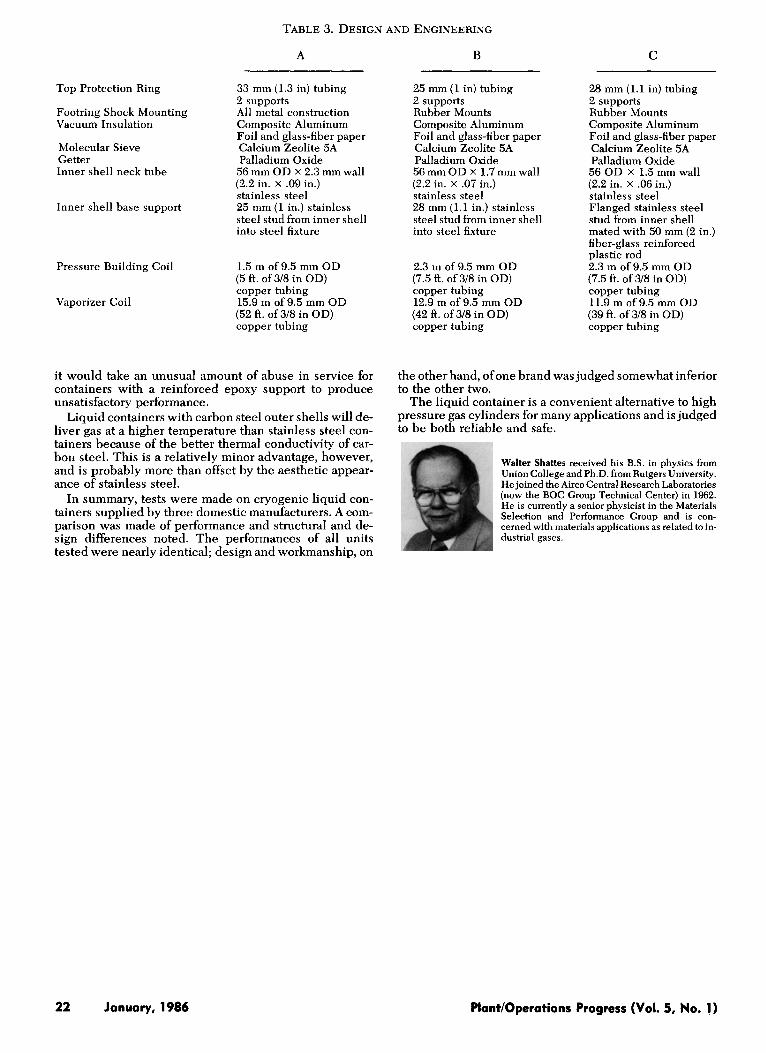
TABLE 3. DESIGN AND ENGINEERING
A B C
Top Protection Ring 33 mm (1.3 in) tubing 2 supports
Footring Shock Mounting All metal construction Vacuum Insulation Composite Aluminum
Foil and glass-fiber paper Molecular Sieve Calcium Zeolite 5A Getter Palladium Oxide Inner shell neck tube 56 mm OD x 2.3 mm wall
(2.2 in. x .09 in.) stainless steel 25 mm (1 in.) stainless steel stud from inner shell into steel fixture
Inner shell base support
Pressure Building Coil
Vaporizer Coil
1.5 m of 9.5 mm OD (5 ft. of 3/8 in OD) copper tubing 15.9 m of 9.5 mm OD (52 ft. of 3/8 in OD) copper tubing
it would take an unusual amount of abuse in service for containers with a reinforced epoxy support to produce unsatisfactory performance.
Liquid containers with carbon steel outer shells will de- liver gas at a higher temperature than stainless steel con- tainers because of the better thermal conductivity of car- bon steel. This is a relatively minor advantage, however, and is probably more than offset by the aesthetic appear- ance of stainless steel.
In summary, tests were made on cryogenic liquid con- tainers supplied by three domestic manufacturers. A com- parison was made of performance and structural and de- sign differences noted. The performances of all units tested were nearly identical; design and workmanship, on
25 mm (1 in) tubing 2 supports Rubber Mounts Composite Aluminum Foil and glass-fiber paper Calcium Zeolite 5A Palladium Oxide 56 mm OD x 1.7 mm wall (2.2 in. x .07 in.) stainless steel 28 mm (1.1 in.) stainless steel stud from inner shell into steel fixture
2.3 111 of 9.5 mm OD (7.5 ft. of 3/8 in OD) copper tubing 12.9 m of 9.5 mm OD (42 ft. of 3/8 in OD) copper tubing
28 mm (1.1 in) tubing 2 supports Rubber Mounts Composite Aluminum Foil and glass-fiber paper Calcium Zeolite 5A Palladium Oxide 56 OD x 1.5 mm wall (2.2 in. x .06 in.) stainless steel Flanged stainless steel stud from inner shell mated with 50 mm (2 in.) fiber-glass reinforced plastic rod 2.3 m of9.5 mm OD (7.5 ft. of 3/8 in OD) copper tubing 11.9 m of 9.5 mm OD (39 ft. of 3/8 in OD) copper tubing
the other hand, ofone brand was judged somewhat inferior to the other two.
The liquid container is a convenient alternative to high pressure gas cylinders for many applications and is judged to be both reliable and safe.
Walter Shattes received his B.S. in physics from Union College and Ph.D. from Rutgers University. He joined the Airco Central Research Laboratories (now the BOC Group Technical Center) in 1962. He is currently a senior physicist in the Materials Selection and Performance Group and is con- cerned with materials applications as related to in- dustrial gases.
22 January, 1986 PlantlOperations Progress (Vol. 5, No. 1)


![Cryotherapy: Physiological Considerations and Applications ...cdn.intechopen.com/pdfs/35000.pdf · Rokita 2006]. Cryogenic liquids, ... Cryotherapy: Physiological Considerations and](https://img.pdfslide.us/doc/110x75/5a9e4c127f8b9a077e8b53ef/cryotherapy-physiological-considerations-and-applications-cdn-2006-cryogenic.jpg)